KR20170051704A - Vehicular multi-operating switching unit - Google Patents
Vehicular multi-operating switching unit Download PDFInfo
- Publication number
- KR20170051704A KR20170051704A KR1020150152116A KR20150152116A KR20170051704A KR 20170051704 A KR20170051704 A KR 20170051704A KR 1020150152116 A KR1020150152116 A KR 1020150152116A KR 20150152116 A KR20150152116 A KR 20150152116A KR 20170051704 A KR20170051704 A KR 20170051704A
- Authority
- KR
- South Korea
- Prior art keywords
- switch
- directional
- housing
- slide
- unit
- Prior art date
Links
- 239000000758 substrate Substances 0.000 claims abstract description 58
- 238000000034 method Methods 0.000 claims description 10
- 238000001514 detection method Methods 0.000 claims description 3
- 230000000149 penetrating effect Effects 0.000 claims 1
- 230000008859 change Effects 0.000 abstract description 9
- 238000003825 pressing Methods 0.000 abstract description 5
- 230000002708 enhancing effect Effects 0.000 abstract 1
- 238000013461 design Methods 0.000 description 5
- 230000004048 modification Effects 0.000 description 5
- 238000012986 modification Methods 0.000 description 5
- 230000007257 malfunction Effects 0.000 description 4
- 230000004323 axial length Effects 0.000 description 3
- 238000010586 diagram Methods 0.000 description 3
- 230000003287 optical effect Effects 0.000 description 3
- 230000002093 peripheral effect Effects 0.000 description 2
- 238000000926 separation method Methods 0.000 description 2
- 230000009194 climbing Effects 0.000 description 1
- 238000004891 communication Methods 0.000 description 1
- 230000006835 compression Effects 0.000 description 1
- 238000007906 compression Methods 0.000 description 1
- 239000012141 concentrate Substances 0.000 description 1
- 230000000881 depressing effect Effects 0.000 description 1
- 230000005684 electric field Effects 0.000 description 1
- 238000009429 electrical wiring Methods 0.000 description 1
- 238000001746 injection moulding Methods 0.000 description 1
- 238000003780 insertion Methods 0.000 description 1
- 230000037431 insertion Effects 0.000 description 1
- 230000003993 interaction Effects 0.000 description 1
- 238000004519 manufacturing process Methods 0.000 description 1
- 239000002184 metal Substances 0.000 description 1
- 238000005192 partition Methods 0.000 description 1
- 230000008569 process Effects 0.000 description 1
- 238000004080 punching Methods 0.000 description 1
- 230000009467 reduction Effects 0.000 description 1
- 102220047090 rs6152 Human genes 0.000 description 1
- 238000000638 solvent extraction Methods 0.000 description 1
- XLYOFNOQVPJJNP-UHFFFAOYSA-N water Substances O XLYOFNOQVPJJNP-UHFFFAOYSA-N 0.000 description 1
Images


Classifications
-
- H—ELECTRICITY
- H01—ELECTRIC ELEMENTS
- H01H—ELECTRIC SWITCHES; RELAYS; SELECTORS; EMERGENCY PROTECTIVE DEVICES
- H01H25/00—Switches with compound movement of handle or other operating part
- H01H25/04—Operating part movable angularly in more than one plane, e.g. joystick
- H01H25/041—Operating part movable angularly in more than one plane, e.g. joystick having a generally flat operating member depressible at different locations to operate different controls
-
- B—PERFORMING OPERATIONS; TRANSPORTING
- B62—LAND VEHICLES FOR TRAVELLING OTHERWISE THAN ON RAILS
- B62D—MOTOR VEHICLES; TRAILERS
- B62D1/00—Steering controls, i.e. means for initiating a change of direction of the vehicle
- B62D1/02—Steering controls, i.e. means for initiating a change of direction of the vehicle vehicle-mounted
- B62D1/04—Hand wheels
- B62D1/046—Adaptations on rotatable parts of the steering wheel for accommodation of switches
-
- H—ELECTRICITY
- H01—ELECTRIC ELEMENTS
- H01H—ELECTRIC SWITCHES; RELAYS; SELECTORS; EMERGENCY PROTECTIVE DEVICES
- H01H25/00—Switches with compound movement of handle or other operating part
- H01H25/04—Operating part movable angularly in more than one plane, e.g. joystick
- H01H2025/048—Operating part movable angularly in more than one plane, e.g. joystick having a separate central push, slide or tumbler button which is not integral with the operating part that surrounds it
-
- H—ELECTRICITY
- H01—ELECTRIC ELEMENTS
- H01H—ELECTRIC SWITCHES; RELAYS; SELECTORS; EMERGENCY PROTECTIVE DEVICES
- H01H2231/00—Applications
- H01H2231/026—Car
Abstract
Description
본 발명은 차량에 장착되는 스위치로서, 복합적인 동작 구현을 이루되 간단하고 컴팩트한 구조를 이루는 차량용 스위치에 관한 것이다. BACKGROUND OF THE INVENTION 1. Field of the Invention [0002] The present invention relates to a switch mounted on a vehicle, which is a simple and compact structure realized in a complex operation.
통상적으로, 차량용 스티어링 휠 어셈블리는 스티어링 휠과, 스티어링 컬럼과, 스티어링 롤 커넥터(Sterring Roll Connector) 어셈블리와 그리고 다기능 스위치 어셈블리 등을 구비한다. 스티어링 휠은 운전자가 조향 방향을 설정하기 위한 것으로, 운전자에 의한 스티어링 휠의 회전은 스티어링 컬럼을 통하여 차륜에 전달되어 차량의 조향각을 설정하게 된다. 또한, 자동차 등의 차량에는 이동 수단으로서의 기능을 넘어서 사용자로 하여금 보다 안정적이면서도 편안한 주행 상태를 제공할 수 있도록 하는 각종 편의 수단으로서 기능이 요구되고 있다. Typically, a steering wheel assembly for a vehicle includes a steering wheel, a steering column, a Sterring Roll Connector assembly, and a multifunctional switch assembly. The steering wheel is for the driver to set the steering direction, and the rotation of the steering wheel by the driver is transmitted to the wheel through the steering column to set the steering angle of the vehicle. In addition, a vehicle such as an automobile has a function as a variety of convenience means for enabling a user to provide a more stable and comfortable running state beyond a function as a moving means.
예를 들어, 근래 생산되는 차량의 스티어링 휠에는 윈도우를 개폐시키는 윈도우 스위치, 조향 라이트를 온/오프시키는 조향 라이트 스위치 및 오디오를 구동시키는 오디오 스위치, 와이퍼를 구동시키는 와이퍼 스위치 등이 배치되고, 다기능 스위치 어셈블리는 라이트 및 포그램프, 와이퍼, 각종 오디오 장치 및 차량 윈도우 스위치 등을 구비하는 것으로 운전자로 하여금 각종 장치의 조작성을 증대시킴으로써, 각종 장치의 조작 중에도 전방 주의력을 상실하지 않도록 하는데, 이는 스티어링 휠의 상부에 버튼 스위치로 구현되거나 스티어링 휠 측면의 차량용 레버 스위치로서 구현되거나 다양한 기능이 콘솔 스위치로 집중된다.For example, a steering wheel of a currently produced vehicle is provided with a window switch for opening and closing a window, a steering light switch for turning on / off a steering light, an audio switch for driving audio, a wiper switch for driving a wiper, The assembly is provided with a light and fog lamp, a wiper, various audio devices, and a vehicle window switch so as to increase the operability of various devices by the driver so as not to lose the front attention during operation of various devices, Or as a lever switch on the side of the steering wheel or various functions are concentrated on the console switch.
근래 자동차의 스위치에 있어서 다양한 기능의 스위치가 복합적으로 집약되는 경향을 나타내는데, 기능의 증대만큼 구조가 복잡해지고 복잡한 구조로 인한 오작동 가능성도 증대된다. Recently, it has been shown that switches of various functions tend to be integrated in a switch of a vehicle. However, as the function increases, the structure becomes complicated and the possibility of malfunction due to a complicated structure is increased.
본 발명은 종래 기술의 문제점을 해결하기 위해 발명한 것으로서, 본 발명의 목적은 컴팩트하고 간단한 구조를 통하여 복합적인 동작 구현을 가능하게 함으로써 내구성을 증진시키고 보다 정확한 동작 구현을 가능하게 하는 차량용 멀티 오퍼레이팅 스위치 유니트를 제공하는 것이다.SUMMARY OF THE INVENTION The present invention has been made to solve the problems of the prior art, and it is an object of the present invention to provide a multi-operating switch for a vehicle which can realize a complex operation through a compact and simple structure, Unit.
본 발명은, 하우징부와, 상기 하우징의 내부에 배치되는 기판과, 일단이 상기 하우징에 수용되고 타단이 상기 하우징에 노출되어 가동 가능하게 배치되는 스위치 샤프트부와, 상기 스위치 샤프트부의 축회동을 감지 출력하는 로터리 스위치부와, 상기 스위치 샤프트부의 틸팅 디텍셔널 동작을 감지 출력하는 디렉셔널 스위치부와, 상기 스위치 샤프트부의 압입 푸시 동작을 감지 출력하는 푸시 스위치부를 구비하고, 상기 디렉셔널 스위치부는: 상기 스위치 샤프트부의 틸팅 디렉셔널 동작에 의하여 상기 하우징부 내에서 위치 가변 가능한 디렉셔널 슬라이드부와, 상기 기판에 배치되고 상기 디렉셔널 슬라이드부의 위치 가변에 의하여 가동되어 변화된 신호를 생성하는 디렉셔널 스위치와, 상기 디렉셔널 슬라이드부 및 상기 스위치 샤프트부를 평면 상에서 원위치 복귀시키는 디렉셔널 리턴부를 구비하되, 상기 디렉셔널 리턴부는: 상기 하우징부에 가동 가능하게 배치되는 리턴 플런저와, 상기 하우징부에 수용되어 상기 리턴 플런저를 탄성지지하는 리턴 탄성부와, 상기 리턴 플런저와 상시 접촉 상태를 형성하고 상기 리턴 플런저를 원위치 복귀시키는 위치를 포함하는 리턴 그루브를 구비하되, 상기 리턴 플런저는 상기 하우징부에 대하여 상기 스위치 샤프트부의 축 길이 방향으로 가동 가능하고, 상기 리턴 그루브는 상기 디렉셔널 슬라이부에 형성되는 것을 특징으로 하는 차량용 멀티 오퍼레이팅 스위치 유니트를 제공한다.The present invention relates to a switch device comprising a housing part, a substrate disposed in the housing, a switch shaft part having one end housed in the housing and the other end exposed to the housing so as to be movable, And a push switch unit for sensing and outputting the push-in push operation of the switch shaft unit, wherein the directional switch unit comprises: a switch unit for switching the switch A directional slide portion that is positionally variable in the housing portion by a tilting directional operation of the shaft portion, a directional switch which is disposed on the substrate and is operated by changing the position of the directional slide portion to generate a changed signal, The slide slide portion and the switch shaft portion The return return portion includes a return plunger movably disposed in the housing portion, a return elastic portion accommodated in the housing portion and elastically supporting the return plunger, Wherein the return plunger is movable in the axial direction of the switch shaft with respect to the housing part, and the return groove is movable in the axial direction of the switch shaft part with respect to the housing part, And wherein the directional slider portion is formed on the directional slider portion.
상기 차량용 멀티 오퍼레이팅 스위치 유니트에 있어서, 상기 하우징부는, 상기 기판을 지지하는 하우징 베이스와, 상기 하우징 베이스와 맞물리어 내부 공간을 형성하고 상기 리턴 플런저가 가동 가능하게 배치되는 리턴 장착부가 형성되는 하우징 커버를 구비할 수도 있다. The housing unit includes a housing base for supporting the substrate and a housing cover formed with a return mounting portion for forming an internal space by engaging with the housing base and movably arranging the return plunger, .
상기 차량용 멀티 오퍼레이팅 스위치 유니트에 있어서, 상기 디렉셔널 슬라이드부는: 상기 하우징 베이스와 상기 하우징 커버 사이에 배치되고 상기 스위치 샤프트부가 관통 배치되는 디렉셔널 미디엄 슬라이드와, 상기 디렉셔널 미디엄 슬라이드 및 상기 하우징 베이스 사이에 배치되고 상기 스위치 샤프트부의 외주에 관통 장착되는 디렉셔널 바텀 슬라이드와, 상기 하우징 커버의 일면으로 상기 디렉셔널 미디엄 슬라이드를 향한 저면에 형성되고 상기 디렉셔널 미디엄 슬라이드와 상대 가동 가능하게 맞물림되는 디렉셔널 탑 슬라이드를 구비할 수도 있다. The directional slide unit may include: a directional medium slide disposed between the housing base and the housing cover, the switch shaft portion being disposed through the switch unit, and a directional medium slide disposed between the directional medium slide and the housing base, A directional bottom slide disposed on the outer periphery of the switch shaft portion and disposed on a bottom surface of the housing cover facing the directional medium slide and being engaged with the directional medium slide relatively movably, .
상기 차량용 멀티 오퍼레이팅 스위치 유니트에 있어서, 상기 디렉셔널 미디엄 슬라이드의 일면에는 상기 디렉셔널 탑 슬라이드와 맞물림 가능하도록 형성되는 미디엄 어퍼 가이드가 형성되고, 상기 디렉셔널 미디엄 슬라이드의 타면에는 미디엄 로워 가이드가 형성되되, 상기 미디엄 로워 가이드는 상기 디렉셔널 바텀 슬라이드에 형성되는 바텀 가이드와 상대 가동 가능하게 맞물림되도록 형성될 수도 있다. In the vehicle multi operating switch unit, a medium upper guide formed to be engageable with the directional top slide is formed on one side of the directional medium slide, a medium lower guide is formed on the other side of the directional medium slide, The medium lower guide may be formed to engage with the bottom guide formed on the directional bottom slide relatively movably.
상기 차량용 멀티 오퍼레이팅 스위치 유니트에 있어서, 상기 디렉셔널 바텀 슬라이드는: 상기 일면 상에 상기 바텀 가이드가 형성되고, 상기 스위치 샤프트부가 관통되고 내측면이 상기 스위치 샤프트부와 접촉하는 바텀 관통구가 구비되는 바텀 슬라이드 바디와, 상기 미디엄 어퍼 가이드와 상기 미디엄 연장 형성되고 상기 리턴 그루브가 형성되는 바텀 슬라이드 사이드와, 상기 바텀 슬라이드 바디의 하부에 형성되어 상기 디렉셔널 스위치를 가동시킬 수 있는 바텀 슬라이드 가동부를 구비할 수도 있다. In the multi-operating switch unit for a vehicle, the directional bottom slide may include: a bottom guide having the bottom guide formed on the one surface thereof, the switch shaft portion being penetrated and the bottom surface of the bottom hole being in contact with the switch shaft portion, And a bottom slide movable part formed at a lower portion of the bottom slide body and capable of moving the directional switch, may be provided in the lower slider body, the slider body, the medium upper guide, have.
상기 차량용 멀티 오퍼레이팅 스위치 유니트에 있어서, 상기 미디엄 어퍼 가이드와 상기 미디엄 로워 가이드는 동일 평면 상에서 투영되는 경우 90도 교차 배치될 수도 있다. In the multi-operating switch unit for a vehicle, the medium upper guide and the medium lower guide may be disposed at an angle of 90 degrees when projected on the same plane.
상기 차량용 멀티 오퍼레이팅 스위치 유니트에 있어서, 상기 리턴 그루브는: 상기 스위치 샤프트부에 외력이 인가되지 않는 정상 상태에서 상기 리턴 플런저와 접촉 상태를 형성하는 그루브 스테이블 포지션과, 상기 그루브 스테이블 포지션의 외측에 배치되고 상기 스위치 샤프트부에 외력이 인가되는 외력 인가 상태에서 상기 리턴 플런저와 접촉 상태를 형성하는 그루브 무빙 포지션을 포함할 수도 있다. Wherein the return groove includes: a groove table position for forming a contact state with the return plunger in a steady state in which no external force is applied to the switch shaft portion; And a groove moving position in which an external force is applied to the switch shaft portion to form a contact state with the return plunger.
상기 차량용 멀티 오퍼레이팅 스위치 유니트에 있어서, 상기 바텀 슬라이드 가동부는 상기 슬라이드 바디의 하부로부터 연장 돌출 형성되는 돌기이고, 상기 디렉셔널 스위치는 접촉 스위치일 수도 있다. In the multi-operating switch unit for a vehicle, the bottom slide movable portion is a protrusion formed to extend from a lower portion of the slide body, and the directional switch may be a contact switch.
상기 차량용 멀티 오퍼레이팅 스위치 유니트에 있어서, 상기 스위치 샤프트부는: 상기 하우징에 수용되는 일단에 배치되고 힌지 동작을 가능하게 하고 외주에 샤프트 힌지 가이드가 배치되는 스위치 샤프트 힌지와, 상기 스위치 샤프트 힌지와 연결되고 일단이 상기 하우징에 노출되고 사전 설정된 길이를 갖는 스위치 샤프트 바디를 구비하고, 상기 로터리 스위치부는: 상기 기판과 상기 하우징부 사이에 배치되고, 상기 스위치 샤프트 힌지의 적어도 일부를 수용 가능하고 상기 샤프트 힌지 가이드와 맞물림 가능한 로터리 엔코더 수용 가이드를 구비하고 외주에 복수 개의 로터리 엔코더 슬릿을 구비하는 로터리 엔코더와, 상기 기판에 상기 로터리 엔코더와 사전 설정된 간격으로 이격되어 배치되고, 상기 로터리 엔코더가 상기 스위치 샤프트부와 함께 축회동하는 경우 상기 로터리 엔코더 슬릿의 이동수를 감지하는 로터리 스위치 센서를 포함할 수도 있다. The switch shaft hinge includes: a switch shaft hinge disposed at one end of the switch housing and accommodated in the housing, the switch shaft hinge being capable of hinge operation and having a shaft hinge guide disposed on an outer periphery thereof; And a switch shaft body exposed to the housing and having a predetermined length, wherein the rotary switch portion is disposed between the substrate and the housing portion, and is capable of receiving at least a portion of the switch shaft hinge, A rotary encoder having a plurality of rotary encoder slits provided on an outer periphery thereof and capable of engaging with a rotary encoder; and a plurality of rotary encoders disposed on the substrate at a predetermined distance from the rotary encoders, When the rotation shaft may include a rotary switch sensor to detect the yidongsu of the rotary encoder slit.
상기 차량용 멀티 오퍼레이팅 스위치 유니트에 있어서, 상기 로터리 스위치부는 상기 로터리 엔코더의 회동 동작을 디텐팅시키는 로터리 디텐트부를 더 구비할 수도 있다. In the multi-operating switch unit for a vehicle, the rotary switch unit may further include a rotary detent unit detenting the turning operation of the rotary encoder.
상기 차량용 멀티 오퍼레이팅 스위치 유니트에 있어서, 상기 로터리 디텐트부는: 상기 로터리 엔코더의 저면에 배치되는 로터리 디텐트와, 상기 하우징부에 배치되는 베이스 로터리 디텐트 수용부에 수용되는 로터리 디텐트 탄성부와, 상기 로터리 디텐트 탄성부에 의하여 탄성 지지되어 상기 로터리 디텐트와 상시 접촉 상태를 형성하는 로터리 디텐트 볼을 구비할 수도 있다. The rotary detent portion includes: a rotary detent disposed on a bottom surface of the rotary encoder; a rotary detent elastic portion accommodated in a base rotary detent accommodating portion disposed in the housing portion; And a rotary detent ball elastically supported by the rotary detent elastic portion to form a normal contact state with the rotary detent.
상기 차량용 멀티 오퍼레이팅 스위치 유니트에 있어서, 상기 로터리 디텐트부는: 상기 로터리 엔코더의 하부 측면에 배치되는 로터리 디텐트와, 상기 로터리 디텐트의 대응되는 위치로 상기 하우징부에 위치 고정되어 장착되는 판 스프링 타입의 로터리 디텐트 탄성부와, 상기 로터리 디텐트 탄성부와 일체를 이루어 절곡 돌출 형성되어 상기 로터리 디텐트와 상시 접촉 상태를 형성하는 로터리 디텐트 탄성 돌기를 구비할 수도 있다. The rotary detent portion includes: a rotary detent disposed on a lower side of the rotary encoder; and a plate detent portion mounted and fixed to the housing portion at a corresponding position of the rotary detent, And a rotary detent elastic projection formed integrally with the rotary detent elastic portion to bend and protrude to establish a normal contact state with the rotary detent.
상기 차량용 멀티 오퍼레이팅 스위치 유니트에 있어서, 상기 로터리 디텐트부는: 상기 로터리 엔코더의 하부 측면에 배치되는 로터리 디텐트와, 상기 하우징부에 상기 스위치 샤프트부의 중심을 향하는 반경 방향으로 배치되는 베이스 로터리 디텐트 수용부에 수용되는 로터리 디텐트 탄성부와, 상기 로터리 디텐트 탄성부에 의하여 탄성 지지되어 상기 로터리 디텐트와 상시 접촉 상태를 형성하는 로터리 디텐트 볼을 구비할 수도 있다. The rotary detent portion includes: a rotary detent disposed on a lower side surface of the rotary encoder; a base detent accommodating portion disposed in the housing portion in a radial direction toward the center of the switch shaft portion; And a rotary detent ball elastically supported by the rotary detent elastic portion to establish a normal contact state with the rotary detent.
상기 차량용 멀티 오퍼레이팅 스위치 유니트에 있어서, 상기 푸시 스위치부는: 상기 로터리 엔코더의 하부 측면으로 상기 로터리 디텐트의 상단에는, 상기 스위치 샤프트부의 길이 방향 및 상기 스위치 샤프트부의 중심으로부터의 반경 방향 상 상기 로터리 디텐트와 층을 이루어 형성되는 푸시 디텐트와, 적어도 일부가 상기 로터리 엔코더에 배치되고 상기 스위치 샤프트부의 상기 스위치 샤프트 힌지가 상기 로터리 엔코더를 가압하여 하방 이동시키는 경우 상기 로터리 엔코더와 함께 수직 가동되는 푸시 가동부와, 상기 기판에 배치되고 상기 푸시 가동부가 수직 방향으로 위치 변동되는 경우 변화된 신호를 생성하는 푸시 스위치를 구비할 수도 있다. Wherein the push switch portion comprises: a lower side surface of the rotary encoder, at an upper end of the rotary detent, in a longitudinal direction of the switch shaft portion and in a radial direction from a center of the switch shaft portion, And a push moving part which is vertically movable together with the rotary encoder when at least a part of the push detent is disposed in the rotary encoder and the switch shaft hinge of the switch shaft part presses down the rotary encoder, And a push switch which is disposed on the substrate and generates a changed signal when the push movable portion is displaced in the vertical direction.
상기 차량용 멀티 오퍼레이팅 스위치 유니트에 있어서, 상기 베이스 로터리 디텐트 수용부의 상기 하우징부의 내측을 향한 단부 상단은 챔퍼링되어 상기 로터리 엔코더의 수직 가동시 상기 로터리 엔코어와의 원치 않는 간섭을 배제하는 가이드 챔퍼링부를 더 구비할 수도 있다. In the vehicle multi operating switch unit, an upper end of an end portion of the base rotary detent receiving portion facing the inside of the housing portion is chamfered to exclude unwanted interference with the rotary encoder during vertical movement of the rotary encoder. .
상기 차량용 멀티 오퍼레이팅 스위치 유니트에 있어서, 상기 푸시 스위치부는: 적어도 일부가 상기 로터리 엔코더의 하부에 배치되고 상기 스위치 샤프트부의 상기 스위치 샤프트 힌지와 접촉하여 상기 스위치 샤프트부가 수직 가동되는 경우 함께 수직 가동되는 푸시 홀더와, 상기 기판에 배치되고 상기 푸시 홀더가 수직 방향으로 위치 변동되는 경우 변화된 신호를 생성하는 푸시 스위치와, 상기 푸시 홀더의 하부에 배치되고 상기 푸시 홀더를 탄성 지지하는 푸시 리턴부를 포함할 수도 있다. Wherein the push switch portion is disposed at a lower portion of the rotary encoder and is in contact with the switch shaft hinge of the switch shaft portion so that when the switch shaft portion is vertically movable, And a push switch disposed on the substrate and generating a changed signal when the push holder is displaced in the vertical direction, and a push return portion disposed at a lower portion of the push holder and elastically supporting the push holder.
상기 차량용 멀티 오퍼레이팅 스위치 유니트에 있어서, 상기 푸시 홀더는: 상기 스위치 샤프트 힌지를 수용 접촉하는 푸시 홀더 바디와, 상기 푸시 홀더 바디의 측면으로부터 연장 형성되는 푸시 홀더 사이드와, 상기 푸시 홀더 사이드로부터 상기 스위치 샤프트부의 수직 가동 방향과 평행하게 연장 형성되어 상기 스위치 샤프트부가 수직 가동되는 경우 상기 푸시 스위치를 가동시키는 푸시 홀더 가동부를 포함할 수도 있다. Wherein the push holder includes: a push holder body for receiving the switch shaft hinge; a push holder side extending from a side surface of the push holder body; and a switch holder shaft extending from the push holder side to the switch shaft, And a push-holder movable portion that extends parallel to the vertical direction of movement of the switch shaft portion and operates the push switch when the switch shaft portion is vertically movable.
상기 차량용 멀티 오퍼레이팅 스위치 유니트에 있어서, 상기 푸시 리턴부는: 상기 푸시 홀더 바디와 접촉하는 푸시 리턴 바디와, 상기 푸시 리턴 바디의 측면으로부터 연장 형성되는 푸시 리턴 사이드와, 상기 푸시 리턴 사이드의 일면 상에 배치되고 상기 푸시 홀더 사이드를 탄성 지지하는 푸시 리턴 러버캡을 포함할 수도 있다. The push-return unit includes: a push-return body in contact with the push-holder body; a push-return side extending from a side of the push-return body; and a push-return body disposed on one side of the push- And a push-return rubber cap for elastically supporting the push-holder side.
상기 차량용 멀티 오퍼레이팅 스위치 유니트에 있어서, 상기 푸시 홀더 바디에는 푸시 홀더 바디 관통구가 형성되고, 상기 푸시 리턴 바디에는 푸시 리턴 바디 관통구가 형성되고, 상기 스위치 샤프트 힌지의 저면에는 샤프트 힌지 스톱퍼가 구비되고, 상기 하우징부의 상기 샤프트 힌지 스톱퍼의 대응되는 위치에는 베이스 푸시 톨러런스가 구비되되, 상기 스위치 샤프트부에 푸시 동작을 이루는 외력만이 인가되는 경우 상기 샤프트 힌지 스톱퍼는 상기 베이스 푸시 톨러런스에 수용 가능하고, 상기 스위치 샤프트부에 틸팅 동작을 이루는 외력이 인가되는 경우 상기 샤프트 힌지 스톱퍼는 상기 베이스 푸시 톨러런스의 외측에 접촉하여 상기 샤프트 힌지 스톱퍼가 상기 베이스 푸시 톨러런스로 수용되는 것이 방지될 수도 있다. In the multi-operating switch unit for a vehicle, a push holder body through-hole is formed in the push holder body, a push-return body through-hole is formed in the push return body, a shaft hinge stopper is provided on a bottom surface of the switch shaft hinge A base push tolerance is provided at a corresponding position of the shaft hinge stopper of the housing part. When only an external force that makes a push operation is applied to the switch shaft part, the shaft hinge stopper is accommodated in the base push tolerance, When an external force for tilting operation is applied to the switch shaft portion, the shaft hinge stopper may contact the outside of the base pushing tolerance to prevent the shaft hinge stopper from being accommodated in the base pushing tolerance.
본 발명의 또 다른 일면에 따르면, 본 발명은 하우징부와, 상기 하우징의 내부에 배치되는 기판과, 일단이 상기 하우징에 수용되고 타단이 상기 하우징에 노출되어 가동 가능하게 배치되는 스위치 샤프트부와, 상기 스위치 샤프트부의 축회동을 감지 출력하는 로터리 스위치부와, 상기 스위치 샤프트부의 틸팅 디텍셔널 동작을 감지 출력하는 디렉셔널 스위치부와, 상기 스위치 샤프트부의 압입 푸시 동작을 감지 출력하는 푸시 스위치부를 구비하고, 상기 디렉셔널 스위치부는: 상기 스위치 샤프트부의 틸팅 디렉셔널 동작에 의하여 상기 하우징부 내에서 위치 가변 가능한 디렉셔널 슬라이드부와, 상기 기판에 배치되고 상기 디렉셔널 슬라이드부의 위치 가변에 의하여 가동되어 변화된 신호를 생성하는 디렉셔널 스위치와, 상기 디렉셔널 슬라이드부 및 상기 스위치 샤프트부를 평면 상에서 원위치 복귀시키는 디렉셔널 리턴부를 구비하되, 상기 디렉셔널 스위치는: 상기 기판의 일면 상에 배치되는 디렉셔널 스위치 하우징과, 상기 디렉셔널 스위치 하우징의 일면 상에 노출 배치되고 상기 디렉셔널 슬라이드부와 접촉 가능하되, 상기 디렉셔널 스위치 하우징의 내부 일지점을 중심으로 상기 기판에 평행한 축을 중심으로 회동하여 가압되는 경우 상기 디렉셔널 슬라이드 하우징의 내부로 수용되는 디렉셔널 스위치 노브를 포함하는 것을 특징으로 하는 차량용 멀티 오퍼레이팅 스위치 유니트를 제공한다. According to another aspect of the present invention, there is provided an electronic apparatus including a housing, a substrate disposed in the housing, a switch shaft portion having one end housed in the housing and the other end exposed to the housing to be movable, A rotary switch unit for sensing and outputting an axial rotation of the switch shaft unit; a direction switch unit for sensing and outputting a tilting detection operation of the switch shaft unit; and a push switch unit for sensing and outputting push- The directional switch unit includes: a directional slide unit that is position-adjustable within the housing unit by a tilting directional operation of the switch shaft unit; and a controller that is disposed on the substrate and is operated by varying a position of the directional slide unit, And a directional slide switch And a directional return portion for returning the switch shaft portion to a home position on a plane, wherein the directional switch comprises: a directional switch housing disposed on one side of the substrate; And a directional switch knob which is contactable with the slide slide portion and is received in the interior of the directional slide housing when it is pivoted about an axis parallel to the substrate about a point within the directional switch housing, The present invention provides a multi-operating switch unit for a vehicle.
상기 차량용 멀티 오퍼레이팅 스위치 유니트에 있어서, 상기 디렉셔널 스위치 노브는 상기 스위치 샤프트부의 중심으로부터 반경 방향으로 배치되고, 상기 기판에 수평한 회동 중심은 상기 디렉셔널 스위치 노브의 길이 방향 중 상기 스위치 샤프트부의 중심을 향한 단부 측에 배치될 수도 있다. Wherein the directional switch knob is arranged in a radial direction from a center of the switch shaft portion, and a center of rotation of the knob is parallel to a center of the switch shaft portion in the longitudinal direction of the directional switch knob As shown in Fig.
상기 차량용 멀티 오퍼레이팅 스위치 유니트에 있어서, 상기 디렉셔널 스위치 하우징의 내부로 상기 디렉셔널 스위치 노브에 탄성 복귀력을 제공하는 디렉셔널 스위치 탄성부와, 상기 디렉셔널 스위치 노브에 의하여 가동되는 디렉셔널 스위치 가동 접점과, 상기 디렉셔널 스위치 노브에 의하여 상기 디렉셔널 스위치 가동 접점이 가동되는 경우 접속 가능하게 대응 배치되는 디렉셔널 스위치 고정 접점을 포함할 수도 있다. A directional switch elastic part for providing an elastic return force to the directional switch knob to the interior of the directional switch housing; a directional switch movable contactor operated by the directional switch knob, And a directional switch fixed contact disposed so as to be connectable when the directional switch movable contact is operated by the directional switch knob.
본 발명에 의하면, 자동차의 실내 스티어링 휠 또는 콘솔 스위치 장치 등에 장착되어 운전자의 차량의 네비게이션 장치, 오디오 멀티미디어 장치 내지 공조 장치 등의 차량의 실내 사용되는 전기적 동작을 선택 내지 조정할 수 있도록 복합적인 동작 구현을 가능하게 하는 스위치 유니트를 제공할 수 있다. According to the present invention, it is possible to implement a complex operation by being installed in an indoor steering wheel of an automobile, a console switch device, or the like so as to be able to select and adjust the electrical operation of the vehicle such as a navigation device, an audio multimedia device, The present invention is not limited thereto.
또한, 본 발명의 차량용 멀티 오퍼레이팅 스위치 유니트는 구성요소를 최소화하고 스위치 센서 등을 단일 기판 측으로 집중시켜 전기적 배선의 문제를 최소화하고 이로 인한 설계 자유도를 증진시킴과 아울러 조립성을 향상시켜 생산성 증진으로 인한 원가 절감을 이룰 수 있다. In addition, the multi-operating switch unit for a vehicle according to the present invention minimizes the number of components and concentrates the switch sensor or the like on a single substrate side to minimize the problem of electrical wiring, thereby improving the degree of freedom in designing, Cost reduction can be achieved.
또한, 본 발명의 차량용 멀티 오퍼레이팅 스위치 유니트는, 단일 기판의 사용 등의 컴팩트한 구성 또는 다양한 동작의 배치 영역의 구획 등을 통하여 장착 공간을 최소화시킬 수 있고 구성요소 간의 간섭으로 인한 오작동 가능성을 방지 내지 최소화시킬 수 있다.Further, the multi-operating switch unit for a vehicle of the present invention can minimize a mounting space through a compact configuration such as the use of a single board or a partition of arrangement areas of various operations, and prevent the possibility of malfunction due to inter- Can be minimized.
또한, 본 발명의 차량용 멀티 오퍼레이팅 스위치 유니트는, 디렉셔널 슬라이드부의 하부에 스위치 샤프트 힌지가 배치되는 구조, 즉, 스위치 샤프트 힌지가 하우징의 하부에 배치되고, 디렉셔널 슬라이드부 및 디렉셔널 스위치를 로터리 스위치부 및 푸시 스위치부보다 높은 위치에 배치되는 구조를 통하여, 디렉셔널 스위치부의 작동을 위한 스위치 샤프트 바디의 스위치 샤프트 힌지를 중심으로 하는 회전각을 최소화시켜 스위치 샤프트 바디의 단부에 배치되는 노브 등이 하우징 등과의 접촉으로 인한 간섭 발생을 방지하여 노브와 하우징과의 이격 거리를 최소화시킴으로써 하우징 커버 관통구 등을 통한 이물 유입을 방지 내지 최소화시킬 수 있고, 노브 등과의 간섭 가능성을 방지 내지 저하시켜 구성요소의 컴팩트한 설계를 가능하게 할 수 있다. In the multi-operating switch unit for a vehicle according to the present invention, the switch shaft hinge is disposed at a lower portion of the directional slide portion, that is, the switch shaft hinge is disposed at the lower portion of the housing, and the directional slide portion and the directional switch are connected to the rotary switch And a knob disposed at an end of the switch shaft body for minimizing a rotation angle around the switch shaft hinge of the switch shaft body for operating the directional switch unit through a structure disposed at a higher position than the push switch unit, It is possible to prevent or minimize the inflow of foreign matter through the housing cover through hole or the like and to prevent or reduce the possibility of interference with the knob and the like, So that a compact design can be realized.
또한, 본 발명의 차량용 멀티 오퍼레이팅 스위치 유니트는, 로터리 디텐트부를 통한 푸시 동작 구현을 가능하게 하여 부품수의 감소 및 제조 원가 절감과 더불어 컴팩트한 구성을 가능하게 할 수 있다. Further, the multi-operating switch unit for a vehicle according to the present invention can realize a push operation through a rotary detent unit, thereby reducing the number of components, reducing manufacturing cost, and enabling a compact configuration.
또한, 본 발명의 차량용 멀티 오퍼레이팅 스위치 유니트는, 디렉셔널 스위치의 가동을 회동 방식 구조를 취하여 가동 동작 과정 상에서의 요구되는 스트로크 공간을 최소화하여 장착 공간을 최소화시킬 수 있고 컴팩트한 구성을 가능하게 하여, 구성요소 간의 간섭으로 인한 오작동 가능성을 방지 내지 최소화시킬 수 있다.In addition, the multi-operating switch unit for a vehicle according to the present invention can minimize the space required for the operation of the directional switch by minimizing the stroke space required for the operation of the vehicle by operating the directional switch, It is possible to prevent or minimize the possibility of malfunction due to interference between components.
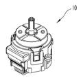
도 1은 본 발명의 일실시예에 따른 차량용 멀티 오퍼레이팅 스위치 유니트의 개략적인 사시도이다.
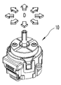
도 2는 본 발명의 일실시예에 따른 차량용 멀티 오퍼레이팅 스위치 유니트의 개략적인 로터리 동작 작동 상태를 도시하는 사시도이다.
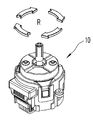
도 3은 본 발명의 일실시예에 따른 차량용 멀티 오퍼레이팅 스위치 유니트의 개략적인 디렉셔널 틸팅 동작 상태를 도시하는 사시도이다.
도 4는 본 발명의 일실시예에 따른 차량용 멀티 오퍼레이팅 스위치 유니트의 개략적인 푸시 동작 상태를 도시하는 사시도이다.
도 5는 본 발명의 일실시예에 따른 차량용 멀티 오퍼레이팅 스위치 유니트의 개략적인 분해 사시도이다.
도 6은 본 발명의 일실시예에 따른 차량용 멀티 오퍼레이팅 스위치 유니트의 개략적인 부분 절단 사시도이다.
도 7은 본 발명의 일실시예에 따른 차량용 멀티 오퍼레이팅 스위치 유니트의 스위치 샤프트부의 개략적인 사시도이다.
도 8은 본 발명의 일실시예에 따른 차량용 멀티 오퍼레이팅 스위치 유니트의 로터리 엔코더의 개략적인 사시도이다.
도 9는 본 발명의 일실시예에 따른 차량용 멀티 오퍼레이팅 스위치 유니트의 개략적인 부분 절단 사시도이다.
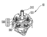
도 10은 본 발명의 일실시예에 따른 차량용 멀티 오퍼레이팅 스위치 유니트의 디렉셔널 틸팅시 디렉셔널 리턴부의 작동 상태를 나타내는 개략적인 부분 절단 측면도이다.
도 11은 본 발명의 일실시예에 따른 차량용 멀티 오퍼레이팅 스위치 유니트의 디렉셔널 틸팅 동작시 작동 상태를 도시하는 개략적인 부분 사시도이다.
도 12는 본 발명의 일실시예에 따른 차량용 멀티 오퍼레이팅 스위치 유니트의 디렉셔널 스위치의 장착 상태를 나타내는 개략적인 사시도이다.
도 13은 본 발명의 일실시예에 따른 차량용 멀티 오퍼레이팅 스위치 유니트의 디렉셔널 틸팅 동작 상태를 나타내는 개략적인 부분 측면도이다.
도 14는 본 발명의 일실시예에 따른 차량용 멀티 오퍼레이팅 스위치 유니트의 개략적인 부분 절단 사시도이다.
도 15는 본 발명의 일실시예에 따른 차량용 멀티 오퍼레이팅 스위치 유니트의 푸시 스위치부의 개략적인 부분 사시도이다.
도 16은 본 발명의 일실시예에 따른 차량용 멀티 오퍼레이팅 스위치 유니트의 디렉셔널 바텀 슬라이드의 저면도이다.
도 17은 본 발명의 일실시예에 따른 차량용 멀티 오퍼레이팅 스위치 유니트의 디렉셔널 틸팅 동작 과정을 나타내는 상태도이다.
도 18 내 도 23은 본 발명의 다른 일실시예에 따른 차량용 멀티 오퍼레이팅 스위치 유니트의 구성에 대한 개략적인 부분 사시도, 부분 측단면도 및 상태도이다.
도 24는 본 발명의 또 다른 일실시예에 따른 차량용 멀티 오퍼레이팅 스위치 유니트의 개략적인 분해 사시도이다.
도 25 및 도 26은 본 발명의 또 다른 일실시예에 따른 차량용 멀티 오퍼레이팅 스위치 유니트의 디렉셔널 스위치에 대한 개략적인 사시도이다.
도 27은 본 발명의 또 다른 일실시예에 따른 차량용 멀티 오퍼레이팅 스위치 유니트의 디렉셔널 스위치에 대한 개략적인 측면도이다.
도 28은 본 발명의 다른 일실시예에 따른 단순한 반경 방향 가동되는 디렉셔널 스위치에 대한 개략적인 측면도이다.
도 29는 본 발명의 또 다른 일실시예에 따른 차량용 멀티 오퍼레이팅 스위치 유니트의 디렉셔널 스위치에 대한 개략적인 부분 측면도이다. 1 is a schematic perspective view of a multi-operating switch unit for a vehicle according to an embodiment of the present invention.
2 is a perspective view showing a schematic rotary operation state of a multi-operating switch unit for a vehicle according to an embodiment of the present invention.
3 is a perspective view showing a schematic directional tilting operation state of a multi-operating switch unit for a vehicle according to an embodiment of the present invention.
4 is a perspective view showing a schematic push operation state of a multi-operating switch unit for a vehicle according to an embodiment of the present invention.
5 is a schematic exploded perspective view of a multi-operating switch unit for a vehicle according to an embodiment of the present invention.
6 is a schematic partial cutaway perspective view of a multi-operating switch unit for a vehicle according to an embodiment of the present invention.
7 is a schematic perspective view of a switch shaft portion of a multi-operating switch unit for a vehicle according to an embodiment of the present invention.
8 is a schematic perspective view of a rotary encoder of a multi-operating switch unit for a vehicle according to an embodiment of the present invention.
9 is a schematic partial cutaway perspective view of a multi-operating switch unit for a vehicle according to an embodiment of the present invention.
10 is a schematic partial cut-away side view showing an operating state of a directional return unit in a directional tilting of a multi-operating switch unit for a vehicle according to an embodiment of the present invention.
11 is a schematic partial perspective view showing an operating state of the multi-operating switch unit for a vehicle according to an embodiment of the present invention in a directional tilting operation.
12 is a schematic perspective view showing a mounted state of a directional switch of a multi-operating switch unit for a vehicle according to an embodiment of the present invention.
13 is a schematic partial side view showing a directional tilting operation state of a multi-operating switch unit for a vehicle according to an embodiment of the present invention.
14 is a schematic partial cut-away perspective view of a multi-operating switch unit for a vehicle according to an embodiment of the present invention.
15 is a schematic partial perspective view of a push switch portion of a multi-operating switch unit for a vehicle according to an embodiment of the present invention.
16 is a bottom view of a directional bottom slide of a multi-operating switch unit for a vehicle according to an embodiment of the present invention.
17 is a state diagram illustrating a directional tilting operation of a multi-operating switch unit for a vehicle according to an embodiment of the present invention.
FIG. 23 is a schematic partial perspective view, partial cross-sectional side view, and state diagram of the configuration of a multi-operating switch unit for a vehicle according to another embodiment of the present invention.
24 is a schematic exploded perspective view of a multi-operating switch unit for a vehicle according to another embodiment of the present invention.
25 and 26 are schematic perspective views of a directional switch of a multi-operating switch unit for a vehicle according to another embodiment of the present invention.
27 is a schematic side view of a directional switch of a multi-operating switch unit for a vehicle according to another embodiment of the present invention.
Figure 28 is a schematic side view of a simple radially actuated directional switch in accordance with another embodiment of the present invention.
29 is a schematic partial side view of a directional switch of a multi-operating switch unit for a vehicle according to another embodiment of the present invention.
이하, 본 발명의 바람직한 실시예를 첨부된 도면들을 참조하여 상세히 설명한다. 우선 각 도면의 구성요소들에 참조부호를 부가함에 있어서, 동일한 구성요소들에 대해서는 비록 다른 도면상에 표시되더라도 가능한 한 동일한 부호를 가지도록 하고 있음에 유의해야 한다. 또한, 본 발명을 설명함에 있어, 관련된 공지 구성 또는 기능에 대한 구체적인 설명이 본 발명의 요지를 흐릴 수 있다고 판단되는 경우에는 그 상세한 설명은 생략한다.Hereinafter, preferred embodiments of the present invention will be described in detail with reference to the accompanying drawings. In the drawings, the same reference numerals are used to designate the same or similar components throughout the drawings. In the following description of the present invention, a detailed description of known functions and configurations incorporated herein will be omitted when it may make the subject matter of the present invention rather unclear.
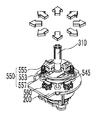
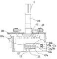
본 발명의 차량용 멀티 오퍼레이팅 스위치 유니트(10)는 하우징부(100)와 기판(200)과 스위치 샤프트부(300)와 로터리 스위치부(400)와 디렉셔널 스위치부(500)와 푸시 스위치부(600)를 포함한다. 본 발명의 차량용 멀티 오퍼레이팅 스위치 유니트(10)는 차량에 사용되는 스위치 유니트로서 다양한 조작 상태 구현을 가능하도록 하여 차량의 다양한 기능, 예를 들어 차량에 구비되는 오디오, 네비게이션, 공조 장치 등의 다양한 차량용 전장 장치 들의 작동 상태를 조정 제어하는데 사용될 수 있다. The
하우징부(100)는 하우징 커버(110)와 하우징 베이스(130)를 구비하는데, 하우징 커버(110)와 하우징 베이스(130)는 서로 체결되어 내부 공간을 형성한다. 하우징 베이스(130)는 기판(200)을 지지하는 구조를 형성하고, 하우징 커버(110)는 하우징 베이스(130)와 맞물리어 체결되어 내부 공간을 형성한다. 하우징 커버(110)의 일면에는 하우징 커버 관통구(111)가 형성되고, 하우징 커버 관통구(111)에는 하기되는 스위치 샤프트부(300)의 일단이 외부로 노출되어 운전자 등의 사용자의 조작력 제공을 가능하게 한다. The
본 실시예의 하우징부(100)는 하우징 홀더(120)를 더 구비하는데, 하우징 홀더(120)는 하우징 커버(110)와 하우징 베이스(130) 사이에 배치되고, 하우징 홀더(120)는 하우징 베이스(130)와 함께 기판(200)을 지지할 수 있고, 하우징 홀더(120)는 하우징 커버(110)와 하우징 베이스(130)가 이루는 공간을 분리하여 하기되는 로터리 스위치부(400)와 디렉셔널 스위치부(500)의 작동시 간섭 발생을 방지하는 공간 분할 기능을 수행할 수 있다. The
기판(200)은 하우징부(100)의 내부에 배치되는데, 기판(200)에는 다양한 전기 소자가 배치될 수 있고 이들 전기 소자는 기판(200)에 형성되는 배선을 통하여 연결될 수도 있고 다른 요소, 예를 들어 플렉서블기판 내지 케이블과 같은 요소들을 통하여 전기적 소통을 이루는 구조를 취할 수도 있다. 기판(200)은 본 실시예에서 양면 기판으로 구현되어 양면에 각종 소자들이 배치될 수 있다. The
기판(200)의 중앙에는 기판 관통구(202)가 형성되어 스위치 샤프트부(300)의 관통 배치를 가능하게 한다. 기판(200)의 일단에는 기판 커넥터(201)가 형성되는데, 기판 커넥터(201)에는 커넥터(203)가 연결되고 커넥터(203)를 통하여 외부 전기 장치, 예를 들어 제어부(미도시)와 같은 외부 전기 장치와의 연결이 이루어질 수 있다. A substrate through-
스위치 샤프트부(300)는 일단이 하우징부(100)에 수용되고 타단이 외부로 노출되는 구조를 취하는데, 스위치 샤프트부(300)는 스위치 샤프트 바디(310)와 스위치 샤프트 힌지(320)를 포함한다. 스위치 샤프트 바디(310)는 사전 설정된 소정의 길이를 갖는 로드 타입으로 구현되고 스위치 샤프트 힌지(320)는 스위치 샤프트 바디(310)의 단부에 배치되어 하우징부(100)의 내부에 수용 배치된다. 본 실시예에서 도시되지는 않았으나 스위치 샤프트 바디(310)의 외부로 노출된 단부에는 스위치 노브(미도시)가 장착되어 운전자 등의 그립을 원활하게 하여 소정의 조작감을 제공할 수 있다. The
스위치 샤프트 바디(310)의 하단에 연결되는 스위치 샤프트 힌지(320)는 본 실시예에서 구형 형상을 취하는데 구체적 설계 사양에 따라 변형된 형상을 구비할 수 있다. 스위치 샤프트 힌지(320)는 스위치 샤프트부(300)의 회동 중심을 이루는데, 스위치 샤프트 힌지(320)는 하우징 홀더(120)와 하기되는 로터리 스위치부(400)의 로터리 엔코더(410)에 형성되는 로터리 엔코더 수용부(411, 도 5 참조)에 의하여 형성되는 공간에 배치되고, 하우징 홀더(120)에 형성되는 하우징 홀더 관통구(121)를 통하여 스위치 샤프트 바디(310)가 관통 배치되는 구조를 형성한다. The
따라서, 사용자에 의하여 스위치 샤프트 바디(310)는 축방향 회전 운동, 수평 가압력을 통한 스위치 샤프트 바디(310)의 스위치 샤프트 힌지(320)를 중심으로 하는 틸팅 운동, 및 스위치 샤프트 바디(310)를 하방향으로 압입하는 압입 푸시 운동 등의 복합적인 운동을 이룰 수 있다. Therefore, the
본 실시예에 따른 스위치 샤프트 바디(310)의 디렉셔널 틸팅 운동의 회동 중심점으로의 기능을 수행하는 스위치 샤프트 힌지(320)의 위치는 하우징부와 기판의 사이, 보다 구체적으로 기판(200)과 하우징 베이스(130)의 사이, 더욱 구체적으로, 기판(200)의 하부에 배치되는 하우징 홀더(120)와 하우징 베이스(130)의 사이에 배치되고, 디렉셔널 스위치부(500)는 기판(200)과 하우징 커버(110) 사이에 배치되는 구조를 취하여 스위치 샤프트 바디(310)의 회동 중심인 스위치 샤프트 힌지(320)로부터 이격되어 상부에 배치되는 디렉셔널 스위치부(500)의 디렉셔널 스위치(560)의 가동을 위하여 요구되는 스위치 샤프트 바디(310)의 디렉셔널 틸팅 운동을 최소화시켜 하우징 커버 등과의 이격 거리를 최소화시켜 하우징 커버 등을 통한 내부로의 이물 유입을 방지할 수 있다.The position of the
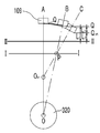
즉, 도 17에는 디렉셔널 틸팅 동작을 구현하는 스위치 샤프트 바디 및 스위치 샤프트 힌지(320)의 동작 상태도가 도시되는데, 스위치 샤프트 바디의 단부에는 노브(109)가 배치된다. 정상 상태에서 스위치 샤프트 바디는 선 O-A 상에 배치되고, 본 발명의 스위치 샤프트 바디의 디렉셔널 틸팅 동작으로 디렉셔널 스위치(560)를 가동시키기 위한 위치를 선 I-I 상의 P라 할 때 스위치 샤프트 바디(310)가 위치 P에 도달할 때의 스위치 샤프트 바디(310)의 길이는 선 O-B 상에 배치되며 이때 노브(109)의 단부는 도면 부호 Q로 지시된 위치를 점유한다. In other words, FIG. 17 shows an operational state diagram of the switch shaft body and the
반면, 본 발명의 구조와 달리 스위치 샤프트 힌지가 가상의 중심점(Ovrt)를 점유하는 경우 디렉셔널 스위치를 가동시키기 위하여 요구되는 위치 P까지 스위치 샤프트가 이동할 때의 스위치 샤프트는 선 Ovrt-C 상에 배치되고, 이 때 노브(109)의 단부는 Qvrt의 위치를 점하게 된다. 선 II-II를 소정의 기준선이라 할 때 선 II-II로부터 각각의 경우에 대한 노브(109)의 단부(Q,Qvrt)의 거리는 L1, L2로 표시되고, L1>L2(L1-L2=L3>0)의 관계를 이루게 된다. On the other hand, unlike the structure of the present invention, when the switch shaft hinge occupies the virtual center Ovrt, the switch shaft when the switch shaft moves to the position P required for operating the directional switch is arranged on the line Ovrt-C At this time, the end of the
즉, 스위치 샤프트 힌지의 하부 배치 구조를 통하여 디렉셔널 스위치(560)를 가동시키기 위하여 요구되는 디렉셔널 틸팅 각도를 최소화시킴으로써 노브(109)의 하우징부를 향한 이동 거리를 최소화시키고 이로부터 노브(109)와 하우징부의 하우징 커버와의 이격 거리를 최소화시킴으로써 하우징 커버 측을 통한 이물 유입 가능성을 저감시키고, 컴팩트한 구성을 가능하게 할 수 있다.That is, by minimizing the directional tilting angle required to operate the
로터리 스위치부(400)는 스위치 샤프트부(300)의 축회동을 감지하고 이를 신호로 제어부(미도시)와 같은 외부 장치로 출력 전달한다. 로터리 스위치부(400)는 로터리 엔코더(410)와 로터리 스위치 센서(420)를 포함하는데, 로터리 엔코더(410)는 기판(20))과 하우징부(100)의 하우징 베이스(130) 사이에 배치되고 스위치 샤프트부(300)의 스위치 샤프트 힌지(320)의 적어도 일부를 수용 가능한 구조를 취한다. 즉, 로터리 엔코더(410)는 로터리 엔코더 수용부(411)가 포함되는데, 로터리 엔코더 수용부(411)는 로터리 엔코더(410)의 중앙에 형성되는 공간으로 로터리 엔코더(410)의 상부에 배치되는 하우징 홀더(120)와 함께 장착 공간을 형성하여 스위치 샤프트 힌지(320)의 안착을 가능하게 한다. The rotary switch unit 400 senses an axial rotation of the
로터리 엔코더(410)의 내측으로 로터리 엔코더 수용부(411)를 구획하는 내측부에 로터리 엔코더 수용 가이드(413)가 형성되고, 스위치 샤프트부(300)의 스위치 샤프트 힌지(320)의 외주에 샤프트 힌지 가이드(321)가 형성되는데, 샤프트 힌지 가이드(321)는 로터리 엔코더 수용 가이드(413)에 수용 배치된다. A rotary
로터리 엔코더 수용 가이드(413)와 샤프트 힌지 가이드(321)는 상대적인 축방향 회동을 방지하도록 맞물리는 구조를 취하는데, 본 실시예에서 로터리 엔도커 수용 가이드(413)와 샤프트 힌지 가이드(321)의 축방향, 측 스위치 샤프트 바디(310)의 축길이 방향을 따른 소정의 상대 가동은 허용되는 구조를 취한다. 즉, 로터리 엔코더 수용 가이드(413)는 스위치 샤프트 바디(310)에 외력이 인가되지 않은 상태에서의 축길이 방향으로 장방형 구조를 취하여 로터리 엔코더 수용 가이드(413)의 로터리 엔코더(410)의 원주 방향에 대한 길이보다 로터리 엔코더(410)의 회전축의 축길이 방향에 대한 길이가 큰 값을 갖는 구조를 취하는데, 로터리 엔코더 수용 가이드(413)의 로터리 엔코더(410)의 원주 방향에 대한 길이를 횡방향 길이 A, 로터리 엔코더(410)의 회전축의 축길이 방향에 대한 길이를 종방향 길이 B라 할 때, 종횡비(AR=B/A)는 1보다 큰 값을 갖도록 구성된다. The rotary
로터리 엔코더(410)의 외주에는 복수 개의 로터리 엔코더 슬릿(415)가 형성되는데, 로터리 엔코더 슬릿(415)의 대응되는 위치에는 로터리 스위치 센서(420)가 배치된다. 즉, 로터리 스위치 센서(420)는 본 실시예에서 광센서로 형성되고, 로터리 스위치 센서(420)는 기판(200)의 하면에 배치된다. 로터리 스위치 센서(420)의 대응되는 위치에 로터리 엔코더(410)의 단부, 즉 로터리 엔코더 슬릿(415)이 가동 가능하게 배치되어, 스위치 샤프트부(300)와 함께 축방향 회동을 이루는 로터리 엔코더(410)의 회전 상태를 로터리 엔코더 슬릿(415)의 이동 회수를 통하여 로터리 스위치 센서(420)가 감지하고 이를 기판(200)을 거쳐 외부 장치로 전달할 수 있다. A plurality of rotary encoder slits 415 are formed on the outer circumference of the
로터리 스위치부(400)의 원치 않는 회동 상태를 방지하고 보다 정확한 회전 신호를 생성함으로써 스위치 샤프트부의 회전 동작을 통한 차량의 장치들의 작동 상태 설정에 있어 오작동을 방지하기 위하여, 스위치 샤프트부(300) 및 로터리 엔코더(410)의 회전 동작을 디텐팅시키는 구성요소를 더 구비할 수 있다. 즉, 본 발명의 로터리 스위치부(400)는 로터리 디텐트부(430)를 포함하는데, 로터리 디텐트부(430)는 로터리 디텐트(431)와 로터리 디텐트 볼(433)과 로터리 디텐트 탄성부(435)를 포함하고, 하우징부(100)의 하우징 베이스(130)에는 베이스 로터리 디텐트 수용부(131)가 구비된다. 베이스 로터리 디텐트 수용부(131)에는 로터리 디텐트 탄성부(435)가 수용 배치된다. In order to prevent an undesired rotation state of the rotary switch unit 400 and to generate a more accurate rotation signal, the
로터리 디텐트(431)는 로터리 엔코더(410)의 저면에 형성되는데, 별도의 구성으로 형성된 후 로터리 엔코더(410)의 저면에 장착될 수도 있으나, 본 실시예에서의 로터리 디텐트(431)는 로터리 엔코더(410)의 저면에 일체로 형성되는 구조를 취한다. 로터리 디텐트(431)는 하나 이상의, 본 실시예에서는 복수 개의 돌기 및 요홈 형상으로 구현되고 소정의 사전 설정된 간격으로 배치되는 구조를 취할 수 있다. 본 실시예에서 도시되는 않았으나 경우에 따라 로터리 엔코더의 과도한 회동을 방지하기 위한 로터리 스톱퍼(미도시)가 더 구비되어 회전 제한 영역을 형성하는 구조를 취할 수도 있고, 회동 제한없이 무한회전을 이루되, 전원 오프시 로터리 스위치 센서의 회동 기준을 초기화시키는 구조를 취할 수도 있는 등 다양한 구성이 가능하다. The
로터리 디텐트(431)의 대응되는 위치에 베이스 로터리 디텐트 수용부(131)가 형성되고, 베이스 로터리 디텐트 수용부(131)에는 코일 스프링 구조의 로터리 디텐트 탄성부(435)가 배치된다. 로터리 디텐트 탄성부(435)는 볼 형상의 로터리 디텐트 볼(433)을 탄성 지지하는데, 로터리 디텐트 볼(433)은 로터리 디텐트(431)와 상시 접촉 상태를 형성한다. 본 실시예에서 로터리 디텐트 탄성부는 코일 스프링으로 구현되었으나, 로터리 디텐트 탄성부는 스파이럴 타입의 판 스프링으로 구현되고 펀칭 돌출된 부분이 로터리 디텐트와 접촉하여 디텐팅 동작을 이루는 등 로터리 디텐팅 동작을 구현하는 범위에서 다양한 구성이 가능하다. A base rotary
한편, 본 발명의 디렉셔널 스위치부(500)는 스위치 샤프트부(300)의 디렉셔널 동작, 즉, 스위치 샤프트부(300)의 스위치 샤프트 바디(310)를 스위치 샤프트 힌지(320)를 중심으로 측면 이동시키는 힘을 인가하는 경우 스위치 샤프트부(300)의 틸팅 동작으로 인하여 발생하는 기판(200)의 평행한 평면 상에서 볼 때 평면 상에서의 일방향으로의 운동 동작을 감지하여 이를 출력한다. The
디렉셔널 스위치부(500)는 디렉셔널 슬라이드부(510)와 디렉셔널 스위치(560)와 디렉셔널 리턴부(550)를 포함한다. 디렉셔널 슬라이드부(510)는 스위치 샤프트부(300)의 틸팅 디렉셔널 동작에 의하여 하우징부(100) 내에서 위치 가변 가능한데, 디렉셔널 슬라이드부(510)는 기판(200)과 평행한 평면 상에서 가동 운동을 이루어, 스위치 샤프트부의 틸팅 운동이 기판에 평행한 평면 상에서 평면 운동으로 전환되는 디렉셔널 스위치부(500)의 디렉셔널 틸팅 운동이 이루어질 수 있다. The
디렉셔널 스위치(560)는 기판(200)에 배치되고 디렉셔널 슬라이드부(510)의 위치 가변에 의하여 가동되어 변화된 신호를 생성하는데, 본 실시예에서 디렉셔널 스위치(560)는 접촉 스위치로 구현되나 설계 사양에 따라 다양한 변형이 가능하다. The
디렉셔널 스위치(560)는 기판(200)의 일면으로 기판(200)의 하우징 커버(110)를 향한 상면에 배치되는데, 하우징 홀더(120)를 통하여 구획 분할되는 상부 영역에 배치되어 가동될 수 있는 구조를 형성한다. The
한편, 본 발명에 따른 디렉셔널 슬라이드부(510)는 디렉셔널 탑 슬라이드(520)와 디렉셔널 미디엄 슬라이드(530)와 디렉셔널 바텀 슬라이드(540)를 포함하는데, 디렉셔널 미디엄 슬라이드(530)는 하우징 베이스(130)와 하우징 커버(110) 사이, 보다 구체적으로는 하우징 커버(110)와 하우징 홀더(120) 사이에 배치되는데, 디렉셔널 미디엄 슬라이드(530)의 중앙에는 미디엄 관통구(533)가 구비되어 스위치 샤프트부(300)의 스위치 샤프트 바디(310)의 관통을 허용한다. The
또한, 디렉셔널 미디엄 슬라이드(530)의 측면에는 미디엄 사이드(535)가 형성되는데, 미디엄 사이드(535)는 디렉셔널 미디엄 슬라이드(530)의 측면에 제거된 홈을 형성하여 하기되는 디렉셔널 리턴부의 구성요소와의 간섭을 배제할 수 있다.A
디렉셔널 미디엄 슬라이드(530)는 소정의 플레이트 구조를 형성하고, 디렉션러 미디엄 슬라이드(530)는 미디엄 어퍼 가이드(531)와 미디엄 로워 가이드(537)를 구비하는데, 미디엄 어퍼 가이드(531)는 디렉셔널 미디엄 슬라이드(530)의 일면, 즉 하우징 커버(110)를 향한 일면에 형성되고, 미디엄 로워 가이드(537)는 디렉셔널 미디엄 슬라이드(530)의 아랫면, 즉 하우징 홀더(120)를 향한 일면에 형성된다. 디렉셔널 탑 슬라이드(520, 도 13 점선 참조)는 하우징 커버(110)의 일면으로 디렉셔널 미디엄 슬라이드(530)를 향한 저면에 형성되고 디렉셔널 미디엄 슬라이드(530)와 상대 가동 가능하게 맞물림되는데, 디렉셔널 탑 슬라이드(520)는 디렉셔널 미디엄 슬라이드(530)의 미디엄 어퍼 가이드(531)와 맞물리어 상대 운동 가능한 구조를 형성하여 하우징부(100)의 내부에서 디렉셔널 미디엄 슬라이드(530)가 미디엄 어퍼 가이드(531) 및 디렉셔널 탑 슬라이드(520)의 길이 방향으로 수평면 상에서의 가동을 이루는 것을 가능하게 한다. The directional
본 실시예에서 디렉셔널 탑 슬라이드(520)는 요홈 형상으로 그리고 미디엄 어퍼 가이드(531)가 돌기 형상으로 구성되는데, 양자는 서로 반대되는 구성을 취할 수도 있는 등 다양한 변형이 가능하다.In this embodiment, the directional
또한, 디렉셔널 미디엄 슬라이드(530)의 타면, 즉 저면에는 미디엄 로워 가이드(537)가 형성되는데, 미디엄 로워 가이드(537)는 하기되는 디렉셔널 바텀 슬라이드(540)의 일면 상에 형성되는 바텀 가이드(541)와 상대 가동 가능하게 맞물림되는 구조를 형성한다. 본 실시예에서 미디엄 로워 가이드(537)는 돌기 구조로 그리고 바텀 가이드(541)는 요홈 구조로 형성되는데, 반대되는 구조를 형성할 수도 있다.A medium
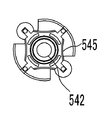
디렉셔널 바텀 슬라이드(540)는 바텀 슬라이드 바디(544)와 바텀 슬라이드 사이드(547)와 바텀 슬라이드 가동부(545)를 포함하는데, 바텀 슬라이드 바디(544)는 일면 상에 상기 기술된 바텀 가이드(541)가 형성되고, 중앙에 바텀 관통구(542)가 형성된다. 바텀 관통구(542)는 상기 미디엄 관통구(533)와 동심 구조를 이루나, 바텀 관통구(542)의 내경은 미디엄 관통구(533)의 내경보다 작은 값을 구비하는데, 바텀 관통구(542)의 내경은 스위치 샤프트부(300)의 스위치 샤프트 바디(310)의 직경에 근사한 값을 구비하여 바텀 관통구(542)의 내측면은 스위치 샤프트 바디(310)의 외주면과 접촉하여 스위치 샤프트부(300)의 틸팅 운동시 디렉셔널 바텀 슬라이드(540)가 함께 수평면 상에서 이동하는 디렉셔널 틸팅 운동을 이룰 수 있다. The directional
바텀 슬라이드 바디(544)의 일면 상에는 바텀 슬라이드 돌기(543)가 형성되어 상면에 배치되는 디렉셔널 미디엄 슬라이드(530)와의 접촉면을 최소화시키는 점접촉 구조를 형성하여 접촉 저항을 줄이는 구조를 더 구비할 수도 있다. 본 실시예에서는 바텀 슬라이드 바디 측에 돌기 구조가 형성되는 구조를 취하였으나 디렉셔널 미디엄 슬라이드 측에 배치되는 구조를 취할 수도 있는 등 변형이 가능하다. A
바텀 슬라이드 사이드(547)는 바텀 슬라이드 바디(544)의 측면으로 연장 형성되는 구조를 이루는데, 경우에 따라서는 별개물로 형성되어 바텀 슬라이드 바디와 체결되는 구조를 취할 수도 있다. 바텀 슬라이드 사이드(547)는 미디엄 사이드(535)의 대응되는 위치에 형성되는데, 바텀 슬라이드 사이드(547)에는 하기되는 리턴 그루브(557)가 형성된다. The
바텀 슬라이드 가동부(545)는 바텀 슬라이드 바디(544)의 하부에 형성되고, 디렉셔널 바텀 슬라이드(540)가 디렉셔널 틸팅 운동을 이루는 경우 바텀 슬라이드 가동부(545)는 기판 상으로 바텀 관통구(542)의 인근 외측 등반경 상으로 등간격 배치되는 디렉셔널 스위치(560)를 가동시킬 수 있다. 본 실시예에서 디렉셔널 스위치(560)는 접촉 스위치로 구현되는데, 바텀 슬라이드 가동부(540)는 디렉셔널 스위치(560)와의 접촉을 가능하게 하는 돌출 구조를 형성한다. 본 실시예에서 디렉셔널 스위치(560)는 4개가 구비되고 바텀 슬라이드 가동부(545)도 이에 대응하여 4개의 가동면을 갖는 사각형 돌출물 구조를 형성하는데, 각각의 할당된 가동면이 디렉셔널 스위치(560)와 접촉을 이루어 디렉셔널 스위치(560)의 변화된 신호 출력을 생성한다. 보다 자세하게는 도 16에 도시된 바와 같이, 바텀 슬라이드 가동부(545)는 디렉셔널 바텀 슬라이드(540)의 저면에 배치되는데, 바텀 슬라이드 가동부(545)는 사각형 돌출물 구조로 형성되나, 접촉시 원활한 가동을 이루고 디렉셔널 동작시 안정적인 접촉 및 분리 동작을 통하여 디렉셔널 스위치의 내구성 저하를 방지할 수 있도록 소정의 내곡된 원호 형상을 갖는 구조로 형성될 수도 있다. The bottom
한편, 본 실시예에서 디렉셔널 스위치는 스위치 샤프트의 중심으로부터 반경 방향으로 가압되는 수평 이동 방식의 디렉셔널 스위치에 대하여 기술되었으나, 본 발명의 차량용 멀티 오퍼레이팅 스위치 유니트의 디렉셔널 스위치는 반경 방향으로의 가압 동작에 국한되는 것은 아니다. 즉, 디렉셔널 바텀 슬라이더는 반경 반향으로의 수평 이동 동작을 이루나, 본 발명의 디렉셔널 스위치도 반드시 수평 이동 동작을 이루는 구성에 한정되는 것은 아니다. On the other hand, in the present embodiment, the directional switch is described as a horizontal directional directional switch that is radially pressed from the center of the switch shaft. However, the directional switch of the multi- But is not limited to operation. That is, the directional bottom slider performs the horizontal movement operation to the radial echo, but the directional switch of the present invention is not necessarily limited to the structure for the horizontal movement operation.
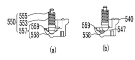
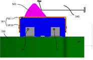
도 24 내지 도 27에는 본 발명의 디렉셔널 스위치의 다른 일예가 도시된다. 발명의 이해를 용이하게 하기 위하여 도면 부호와 명칭을 동일하게 유지한다. 디렉셔널 스위치(560)는 디렉셔널 스위치 하우징(561)과 디렉셔널 스위치 노브(563)를 포함하고, 디렉셔널 스위치 하우징(561)의 내부에 배치되는 디렉셔널 스위치 접점(565,567)은 디렉셔널 스위치 노브(563)를 통하여 가동된다. Figs. 24 to 27 show another example of the directional switch of the present invention. In order to facilitate understanding of the invention, the reference numerals and names are the same. The
디렉셔널 스위치 하우징(561)은 기판(200)의 일면 상에 배치되는데, 스위치 샤프(300)를 중심으로 등반경 등간격 배치 구조를 취하는 것이 바람직하다. The
디렉셔널 스위치 하우징(561)은 디렉셔널 스위치 하우징 커버(5611)와 디렉셔널 스위치 하우징 바디(5613)를 포함하는데, 디렉셔널 스위치 하우징 커버(5611)와 디렉셔널 스위치 하우징 바디(5613)는 서로 맞물리어 내부 공간을 형성하고 내부 공간에 디렉셔널 스위치 노브(563) 등의 적어도 일부가 수용 배치되는 구조를 취한다. The
본 실시예에서 디렉셔널 스위치 하우징(561)은 디렉셔널 스위치 하우징 커버(5611)와 디렉셔널 스위치 하우징 바디(5613)를 포함하는 구조를 취하였으나, 경우에 따라 디렉셔널 스위치 하우징 커버만 기판의 일면 상에 고정 장착 가능한 구조를 취하거나, 디렉셔널 스위치 하우징 바디와 기판이 일체화되어 사출 형성되는 구조를 취할 수도 있는 등 설계 사양에 따라 다양한 구성이 가능하다. In the present embodiment, the
디렉셔널 스위치 하우징(561)의 일면으로 기판(200)이 향하는 일면의 방향과 동일한 방향으로 디렉셔널 스위치 하우징 노브 관통구(5612)이 배치된다. A directional switch housing knob through-
디렉셔널 스위치 노브(563)은 적어도 일부가 디렉셔널 스위치 하우징의 일면 상에 노출 가능하록 디렉셔널 스위치 하우징(561)에 배치된다. 디렉셔널 스위치 노브(563)의 노출된 부위는 디렉셔널 슬라이드부와 접촉 가능한 구조를 취한다. 디렉셔널 스위치 노브(563)는 디렉셔널 스위치 하우징(561)의 내부 일지점을 중심으로 기판(200)에 평행한 축을 중심으로 회동 가능한 구조를 취한다. The
도 27에 도시된 바와 같이, 디렉셔널 스위치 노브(563)는 외력이 가해지지 않는 정상 상태의 경우 디렉셔널 스위치 하우징 노브 관통구(5612)의 일면 상으로 노출되어 배치된다. 디렉셔널 슬라이드부의 디렉셔널 바텀 슬라이드(540)의 바텀 슬라이드 가동부(545)가 기판과 평행한 평면 상에서 수평 이동하는 경우 디렉셔널 스위치 노브(563)는 디렉셔널 스위치 하우징(561)의 내부 일지점을 중심으로 회동하여 디렉셔널 스위치 하우징(561)의 내측으로 진입한다. As shown in Fig. 27, the
디렉셔널 스위치 노브(563)가 회동하는 일지점, 즉 디렉셔널 스위치 노브(563)의 회동점은 스위치 샤프트(300)의 중심을 향한 단부 측에 배치된다. 보다 구체적으로, The turning point of the
디렉셔널 스위치 노브(563)는 스위치 샤프트(300)의 중심으로부터 반경 방향으로 배치된다. 즉, 디렉셔널 스위치 노브(563)는 스위치 샤프트(300)의 중심에서 반경 방향으로 길이 방향을 갖도로 배치되는데, 디렉셔널 스위치 노브(563)는 기판(200)에 수직하게 배치되고 기판(300)에 수평하게 배치되는 회동축을 중심으로 회동하는 구조를 취하는데, 디렉셔널 스위치 노브(563)의 회동 중심은 디렉셔널 스위치 노브(563)의 길이 방향 중 반경 상 먼 측이 아닌 스위치 샤프트의 중심을 향한 단부 측에 배치된다. 즉, 도 27에 도시된 바와 같이, 디렉셔널 스위치 노브(563)는 도면 부호 CO이 아닌 도면 부호 CI를 중심으로 회동 가능하게 배치되는 구조를 취한다. 이러한 반경상 내측 지점을 회동 중심으로 함으로써, 디렉셔널 슬라이드부의 바텀 슬라이드 가동부의 이동에 대하여 디렉셔널 스위치 노브의 점짐적 회동을 가능하게 함으로써 디렉셔널 스위치 자체의 설계 자유도를 향상시킬 수도 있다. The
또한, 디렉셔널 스위치 노브(563)에 인가되는 외력 제거시 원위치 복귀하기 위한 디렉셔널 스위치 탄성부(564)와 디렉셔널 스위치 접점부(565,567)이 구비되는데, 디렉셔널 스위치 탄성부(564) 및 디렉셔널 스위치 접점부(565,567)는 디렉셔널 스위치 하우징의 내부에 배치될 수 있다. A directional switch
도 29에는 본 발명의 디렉셔널 스위치 탄성부 및 디렉셔널 스위치 접점부에 대한 일예가 도시된다. 즉, 디렉셔널 스위치 탄성부(564)는 디렉셔널 스위치 하우징(561)의 내부로 디렉셔널 스위치 노브(563)에 탄성 복귀력을 제공하는데, 디렉셔널 스위치 탄성부(564)는 디렉셔널 스위치 노브(563)의 회동 중심(CI)에 직접 연결되는 구조를 취할 수도 있다. 즉, 본 실시예에서 디렉셔널 스위치 탄성부(564)는 토션 스프링으로 구현되어 디렉셔널 스위치 노브(563)의 초기 탄성력으로 지지하고 외력 제거시 복원력에 의하여 디렉셔널 스위치 노브(563)를 원위치 복귀시키는 구조를 취한다. 29 shows an example of a directional switch elastic portion and a directional switch contact portion of the present invention. That is, the directional switch
디렉셔널 스위치 접점부(565,567)는 디렉셔널 스위치 가동 접점(565)와 디렉셔널 스위치 고정 접점(567)를 포함하는데, The directional
디렉셔널 스위치 가동 접점(565)은 디렉셔널 스위치 노브(563)에 의하여 가동되는데, 디렉셔널 스위치 가동 접점(565)은 디렉셔널 스위치 노브(563)의 저면에 배치되는 구조를 취할 수 있다. The directional switch
디렉셔널 스위치 고정 접점(567)는 디렉셔널 스위치 노브(563)에 의하여 디렉셔널 스위치 가동 접점(565)이 가동되는 경우 접속 가능하게 대응 배치되는데, 디렉셔널 스위치 고정 접점(567)은 디렉셔널 스위치 하우징 바디(5613)에 형성되고 모듈화된 디렉셔널 스위치의 커넥터(미도시)를 통하여 기판(200)을 거쳐 외부 전기 장치 등과 전기적 소통을 이루는 구조를 취할 수 있다. 또한, 경우에 따라 앞서 기술된 바와 같이, 디렉셔널 스위치 하우징 바디와 기판이 일체화되어 인서트 사출되는 경우 기판에 디렉셔널 스위치 고정 접점도 기판에 일체 형성될 수도 있다. The directional switch fixed
이와 같이 디렉셔널 스위치 노브(563)는 기판에 평행한 일면 상에 노출 배치되고 회동 방식을 통하여 가동되는 구조를 취하여, 단순한 반경 방향으로의 가동에 의하여 요구되는 스트로크 공간(dc, 도 27 및 도 28 참조)에 대비하여 가동 공간을 상당히 축소함으로써 보다 컴팩트한 장치 구성이 가능하다. As described above, the
상기 디렉셔널 슬라이드부(510)의 디렉셔널 틸팅 운동, 즉 스위치 샤프트의 틸팅 운동에 의한 수평면 상에서의 수평 슬라이딩 운동인 디렉셔널 틸팅 운동은 디렉셔널 톱 슬라이드, 디렉셔널 미디엄 슬라이드 및 디렉셔널 바텀 슬라이드의 상대 운동을 통하여 이루어질 수 있는데, 디렉셔널 탑 슬라이드와 미디엄 어퍼 가이드 간의 상대 운동, 미디엄 로워 가이드와 바텀 가이드 간의 상대 운동을 통하여 이룰 수 있다. 본 실시예에서 미디엄 어퍼 가이드와 미디엄 로워 가이드는 동일 평면 상에 투영되는 경우 각각의 길이가 이루는 방향이 90도 교차 배치되는 구조를 취하여, 실질적으로 디렉셔널 틸팅 운동의 수평면 상에서의 어느 위치로의 운동도 가능하게 할 수 있다. The directional tilting motion, which is the horizontal sliding movement on the horizontal plane due to the directional tilting motion of the
한편, 상기 기술된 바와 같이 디렉셔널 스위치부(500)는 디렉셔널 리턴부(550)를 포함하는데, 디렉셔널 리턴부(550)는 스위치 샤프트부에 인가되는 외력 제거후 디렉셔널 슬라이드부(510) 및 스위치 샤프트부(300)를 평면 상에서 원위치 복귀시킨다. 디렉셔널 리턴부(550)는 리턴 탄성부(553)와 리턴 플런저(555)와 리턴 그루브(557)를 포함하는데, 리턴 플런저(555)는 하우징부(100)에 가동 가능하게 수용된다. 즉, 하우징부(100)의 하우징 커버(110)에는 리턴 장착부(551)가 형성되는데, 리턴 장착부(551)에 리턴 플런저(555)가 가동 가능하게 수용 배치된다. 리턴 플런저(555)는 로드 타입으로 형성되고, 리턴 플런저(555)의 단부는 리턴 그루브(557)를 향하여 배치된다. 리턴 플런저(555)가 배치되는 리턴 장착부(551)에는 리턴 탄성부(553)가 배치되는데, 리턴 탄성부(553)는 리턴 장착부(551)의 내부 일면에 의하여 지지되고 타단은 리턴 플런저(555)의 외주면과 접촉하여 리턴 플런저(555)를 하우징 커버(110)에 대하여 탄성 지지한다.As described above, the
리턴 그루브(557)는 리턴 플런저(555)와 상시 접촉 상태를 형성하고 외력이 제거되는 정상 상태의 경우 리턴 플런저(555)와 리턴 탄성부(553)와의 상호 작용을 통하여 리턴 플런저(555)를 원위치 복귀시켜, 궁극적으로 디렉셔널 슬라이드부(510)를 원위치 복귀시키는데, 리턴 플런저(555)는 하우징부(100)의 리턴 장착부(551)에서 스위치 샤프트부(300)의 스위치 샤프트 바디(310)의 축길이 방향과 평행하게 축길이 방향으로 가동 가능하게 리턴 탄성부(553)에 의하여 탄성 지지되도록 배치되고, 리턴 그루브(557)는 디렉셔널 바텀 슬라이드(540)의 바텀 슬라이드 사이드(547)에 형성된다. The
리턴 그루브(557)는 그루브 스테이블 포지션(558)과 그루브 무빙 포지션(559)을 포함하는데, 그루브 스테이블 포지션(558)은 스위치 샤프트부(300)의 스위치 샤프트 바디(310)에 외력이 인가되지 않는 정상 상태에서 리턴 플런저(555)의 단부와 접촉 상태를 형성하고, 그루브 무빙 포지션(559)은 그루브 스테이블 포지션(558)의 외측에 배치되고 스위치 샤프트부(300)의 스위치 샤프트 바디(310)에 외력이 인가되어 스위치 샤프트 바디(310)가 중심위치로부터 측방향으로 이동하는 경우 리턴 플런저(555)와 접촉 상태를 형성한다. The
이와 같은 디렉셔널 리턴부(550)의 간결한 동작을 통하여 스위치 샤프트 바디(310)의 길이 방향에 수직한 외력 성분이 인가후 제거되는 경우 스위치 샤프트 바디(310)가 원위치로 안정적으로 복귀 동작을 이룰 수 있다. When the external force component perpendicular to the longitudinal direction of the
본 발명의 푸시 스위치부(600)는 스위치 샤프트부(300)의 압입 푸시 동작을 감지 출력하는데, 푸시 스위치부(600)는 푸시 홀더(610)와 푸시 스위치(620)와 푸시 리턴부(630)를 구비한다. The push switch unit 600 senses and outputs push and push operations of the
푸시 홀더(610)는 적어도 일부가 로터리 엔코더(410)의 하부에 배치되어 스위치 샤프트부(300)의 스위치 샤프트 힌지(320)와 접촉하여 스위치 샤프트부(300)가 수직 가동되는 경우 함께 수직 가동된다. 푸시 스위치(620)는 광센서로 구현될 수 있다. 본 실시예에서는 광센서로 구현되는 경우를 중심으로 기술되나, 경우에 따라 비접촉식 자기 센서 스위치 및 마그네트 구조로 형성될 수도 있는 등 다양한 변형이 가능하다. At least a portion of the
푸시 스위치 홀더(620)가 수직 방향으로 위치 변동되는 경우 푸시 스위치 홀더(620)에 의하여 가동되어 변화된 신호를 생성하는데, 푸시 스위치(620)는 기판(200)의 저면으로 로터리 스위치 센서(420)의 인근에 배치된다. 푸시 리턴부(630)는 푸시 홀더의 하부에 배치되고 푸시 홀더(610)를 탄성 지지하여 푸시 홀더(610)에 가해지는 외력이 제거되는 경우 푸시 홀더(610)를 원위치 복귀시킨다.The
보다 구체적으로 푸시 홀더(610)는 푸시 홀더 바디(611)와 푸시 홀더 사이드(615)와 푸시 홀더 가동부(617)를 포함하는데, 푸시 홀더 바디(611)는 중앙에 푸시 홀더 바디 관통구(613)를 구비하고 푸시 홀더 바디 관통구(613)를 통하여 스위치 샤프트 힌지(320)의 샤프트 힌지 스톱퍼(325)가 관통 배치되는 구조를 이룰 수 있다. 푸시 홀더 사이드(615)는 푸시 홀더 바디(611)의 외측으로 푸시 홀더 바디(611)의 측면으로부터 연장 형성되는데, 푸시 홀더 사이드(615)에는 푸시 홀더 가동부(617)가 배치된다. 푸시 홀더 가동부(617)는 푸시 홀더 사이드(615)로부터 스위치 샤프트부(310)의 수직 가동 방향과 평행하게 연장 형성되어 스위치 샤프트부(300)가 수직 가동되는 경우 푸시 스위치(620)를 가동시키는데, 푸시 홀더 가동부(617)는 기판(200) 측을 향하여 상방향으로 연장 형성되고, 외력이 가해지지 않은 경우 푸시 홀더 가동부(617)의 단부가 푸시 스위치(620)의 수광부(미도시)와 발광부(미도시) 사이에 배치되고, 푸시 압입력이 가해져 푸시 홀더 가동부(617)가 이동하는 경우 푸시 스위치(620)로부터 이격되어 소정의 신호 변화를 생성하도록 한다. More specifically, the
외력이 제거되고 난 후, 푸시 스위치부(600)의 원위치 복귀를 위하여 푸시 리턴부(630)가 더 구비되는데, 푸시 리턴부(630)는 푸시 리턴 바디(631)와 푸시 리턴 사이드(633)와 푸시 리턴 러버캡(635)를 포함한다. 푸시 리턴 바디(621)는 중앙에 푸시 리턴 바디 관통구(632)가 형성되어 소정의 링 형상을 구비하는데, 샤프트 힌지 스톱퍼(325)의 가동을 가능하게 한다. The
푸시 홀더 바디(611)의 하부에 배치되어 푸시 홀더 바디(611)와 접촉 가능한 구조를 취한다. 푸시 리턴 사이드(633)가 푸시 리턴 바디(621)의 외주로부터 연장 형성되는데, 푸시 리턴 사이드(633)의 일면으로부터 푸시 리턴 러버캡(635)이 돌출 배치된다. 푸시 리턴 바디, 푸시 리턴 사이드 및 푸시 리턴 러버캡은 일체화될 수도 있고 서로 체결되는 구조를 형성할 수도 있는 등 다양한 변형이 가능하다. And is disposed at the lower portion of the
푸시 리턴 러버캡(635)은 푸시 홀더 사이드(615)를 탄성 지지하여 수직 가압력이 제거되는 경우 푸시 홀더를 원위치 복귀시킨다. The push return
또한, 푸시 리턴부를 통한 원위치 복귀하는 경우 푸시 홀더의 안정적인 원위치 복귀를 위한 안내 구성요소가 더 구비될 수도 있다. 즉, 도 5에 도시된 바와 같이 하우징 베이스(130)의 내측에는 베이스 푸시 가이드(133)가 형성되고, 베이스 푸시 가이드(133)를 따라 푸시 홀더 가동부(617)의 측단이 삽입되어 안정적인 상대 수직 가동 구조를 형성할 수 있다. Further, it may further comprise a guiding component for stable home position return of the push holder in the case of home return through the push return portion. 5, a
한편, 원치 않는 두 개의 동작이 동시에 구현되어, 예를 들어 푸시 동작과 디렉셔널 틸팅 동작이 동시에 이루어져 신호 출력 혼선이 발생하는 것을 방지하는 구조를 더 구비할 수도 있다. 즉, 스위치 샤프트 힌지(320)의 저면에 형성되는 샤프트 힌지 스톱퍼(325)의 대응되는 위치에는 베이스 푸시 톨러런스(135)가 형성되고, 베이스 푸시 톨러런스(135)의 외주에는 베이스 푸시 스톱퍼(137)가 형성된다. 베이스 푸시 톨러런스는 소정의 요홈 구조를 취하는데, 푸시 동작을 이루는 경우 스위치 샤프트 힌지(320)의 하단에 배치되는 샤프트 힌지 스톱퍼(325)를 수용을 허용한다. 반면, 디렉셔널 틸팅 동작시 스위치 샤프트 바디가 축 길이 방향 압입력이 인가되는 경우 샤프트 힌지 스톱퍼(325)는 베이스 푸시 스톱퍼(137)와 접촉 가능한 구조를 형성하여 스위치 샤프트 바디의 압입 동작을 방지할 수 있다. Meanwhile, it may further include a structure for preventing two undesired operations from being simultaneously implemented, for example, a push operation and a directional tilting operation being performed at the same time to cause a signal output crosstalk. The
한편, 상기 실시예에서 로터리 스위치부의 로터리 디텐트부는 로터리 엔코더의 저면에 배치되는 경우에 대하여 기술하였으나, 본 발명에 따른 로터리 디텐트부의 구조가 이에 한정되는 것은 아니다. 도 18 내지 도 23에는 본 발명의 차량용 멀티 오퍼레이팅 스위치 유니트의 다른 일예들이 도시된다. Meanwhile, although the rotary detent portion of the rotary switch portion is disposed on the bottom surface of the rotary encoder in the above embodiment, the structure of the rotary detent portion according to the present invention is not limited thereto. Figs. 18 to 23 show other examples of the multi-operating switch unit for a vehicle of the present invention.
도 18 및 도 19에는 로터리 디텐트부(430b)의 변형예가 도시된다. 즉, 로터리 디텐트부(430b)는 앞선 실시예에서와는 달리 하부 측면에서 디텐팅되는 구조를 취한다. 로터리 디텐트부(430b)는 로터리 디텐트(431)와 로터리 디텐트 탄성부(433)와 로터리 디텐트 탄성 돌기(435)를 포함하는데, 로터리 엔코더(410)는 앞선 실시예에서와 동일하나 로터리 디텐트(431)는 로터리 엔코더(410)의 하부 측면에 배치되는 구조를 취하고, 로터리 디텐트는 하나 이상의 돌기/요홈 구조로 형성되고, 로터리 디텐트 탄성부(433)는 하우징부(100)의 하우징 베이스(130)에 장착되는데, 로터리 디텐트 탄성부(433)는 판 스프링 타입으로 구현된다. 즉, 로터리 디텐트 탄성부(433)는 예를 들어 금속 플레이트와 같은 소정의 탄성력을 구비하는 탄성편으로 형성되고, 로터리 디텐트 탄성 돌기(435)는 로터리 디텐트 탄성부(433)와 일체로 형성되되, 로터리 디텐트 탄성부(433)의 중앙에서 돌출 절곡되어 형성되고 로터리 디텐트(431)와 상시 접촉 상태를 형성한다. 18 and 19 show a modification of the rotary detent portion 430b. That is, the rotary detent portion 430b is structured to be detentable from the lower side, unlike the previous embodiment. The rotary detent portion 430b includes a
로터리 디텐트 탄성부(433) 및 로터리 디텐트 탄성 돌기(435)는 하나 이상이 구비될 수 있는데, 본 실시예에서는 원활한 디텐팅 동작과 더불어 로터리 엔코더(410)의 회동시 어느 일측으로 기울어지지 않고 안정적인 지지 상태를 형성하도록 3개의 로터리 디텐트 탄성부(433) 및 로터리 디텐트 탄성 돌기(435)가 로터리 엔코더의 회동축에 평행한 평면 상에서 등각 분할 배치되는 구조를 취한다. The rotary detent
또한, 도 20 내지 도 23에는 본 발명의 차량용 멀티 오퍼레이팅 스위치 유니트의 하부 측면에서 로터리 엔코더의 회동에 대한 디텐팅 동작이 이루어지는 또 다른 변형예가 도시된다. 로터리 엔코더(410)의 외주에는 복수 개의 로터리 엔코더 슬릿(415)이 형성되는데, 로터리 엔코더 슬릿(415)의 대응되는 위치에는 로터리 스위치 센서(420)가 배치된다. 20 to 23 show another modification in which the detent operation is performed on the rotation of the rotary encoder at the lower side of the multi-operating switch unit for a vehicle of the present invention. A plurality of rotary encoder slits 415 are formed on the outer periphery of the
로터리 디텐트부(430a)는 로터리 스위치부의 원치 않는 회동 상태를 방지하고 보다 정확한 회전 신호를 생성함으로써 스위치 샤프트부의 회전 동작을 통한 차량의 장치들의 작동 상태 설정에 있어 오작동을 방지하고 조작감을 제공하기 위하여, 스위치 샤프트부(300) 및 로터리 엔코더(410)의 회전 동작을 디텐팅시키는데, 로터리 디텐트부(430a)는 로터리 디텐트(431a)와 로터리 디텐트 볼(433a)과 로터리 디텐트 탄성부(435a)를 포함한다. The rotary detent part 430a prevents an undesired rotation state of the rotary switch part and generates a more accurate rotation signal so as to prevent a malfunction in the operation state setting of the devices of the vehicle through the rotation operation of the switch shaft part, The
하우징부(100)의 하우징 베이스(130)에는 베이스 로터리 디텐트 수용부(131a,132a)가 구비된다. 베이스 로터리 디텐트 수용부(131a,132a)는 하우징 베이스(130)의 하부 측부에 반경 방향으로 형성되는데, 베이스 로터리 디텐트 수용부(131a,132a)에는 디텐트 홀더(436a)가 삽입 배치되고, 베이스 로터리 디텐트 수용부(131a,132a)에는, 보다 구체적으로 디텐트 홀더(436a)의 내측에는 로터리 디텐트 탄성부(435a)의 일단이 접촉하고 로터리 디텐트 탄성부(435a)의 타단은 로터리 디텐트 볼(433a)과 접촉하고, 로터리 디텐트 탄성부(435a)는 로터리 디텐트 볼(433a)에 소정의 탄성력을 제공하여 로터리 디텐트 볼(433a)과 로터리 디텐트(431a) 간의 상시 접촉 구조를 형성한다. The
즉, 베이스 로터리 디텐트 수용부(131a,132a)는 베이스 로터리 디텐트 수용부 홀더 관통구(132a)와 베이스 로터리 디텐트 수용부 가이드(131a)를 구비하는데, 베이스 로터리 디텐트 수용부 가이드(131a)는 하우징 베이스(130)의 하부 측부로 내측면에 형성되고, 베이스 로터리 디텐트 수용부 홀더 관통구(132a)는 하우징 베이스(130)의 하부 측부로 베이스 로터리 디텐트 수용부 가이드(131a)의 외측에 하우징 베이스(130)를 관통하여 형성된다. 디텐트 홀더(436a)은 디텐트 홀더 장착부(347a)를 구비하고 디텐트 홀더 장착부(347a)는 베이스 로터리 디텐트 수용부 홀더 관통구(132a)에 삽입하여 디텐트 홀더(346a)가 하우징 베이스(130)에 안정적인 장착 상태를 형성 가능하게 한다. That is, the base rotary
베이스 로터리 디텐트 수용부 가이드(131a)는 하우징 베이스(130)의 내측면에서 하우징 베이스(130)의 중심을 향하여 연장 형성되는 튜브 구조를 이루는데, 베이스 로터리 디텐트 수용부 가이드(131a)는 양단이 개방된 구조를 형성하여 로터리 디텐트 탄성부(435a)의 삽입 배치 조립 과정을 용이하게 하고, 로터리 디텐트 탄성부(435a)의 안정적인 압축 가동을 가능하게 하고, 로터리 디텐트 볼(433)의 적어도 일부를 수용하여 로터리 디텐트 볼(433)의 로터리 엔코더(410)의 하부 측면에 형성된 로터리 디텐트(431a)와의 상시 접촉을 통한 안정적인 가동 상태를 가능하게 할 수 있다. 베이스 로터리 디텐트 수용부 가이드(131a)의 외주면에는 가이드 돌기(136)가 형성되고 디텐트 홀더(436a)의 디텐트 홀더 장착부(437a)에는 디텐트 홀더 장착 수용부(438a)가 구비되는데, 가이드 돌기(136)는 디텐트 홀더 장착 숭요부(438a)와 맞물리어 디텐트 홀더(346a)가 하우징 베이스(130)로부터 원치 않게 분리 이탈되는 것을 방지할 수도 있다. The base rotary detent receiving
디텐팅 구조에 대하여 부연하면, 로터리 디텐트(431)는 로터리 엔코더(410)의 하부 측면, 보다 구체적으로 로터리 엔코더(410)의 하부로 로터리 엔코더(410)의 회전 중심으로부터 반경 방향에 수직한 외주면에 형성되는 구조를 취한다. 로터리 디텐트(431)는 소정의 사전 설정된 간격으로 배치되는 구조를 취할 수 있다. 본 실시예에서 도시되는 않았으나 경우에 따라 로터리 엔코더의 과도한 회동을 방지하기 위한 로터리 스톱퍼(미도시)가 더 구비되어 회전 제한 영역을 형성하는 구조를 취할 수도 있고, 회동 제한없이 무한회전을 이루되, 전원 오프시 로터리 스위치 센서의 회동 기준을 초기화시키는 구조를 취할 수도 있는 등 다양한 구성이 가능하다.The
한편, 이와 같은 로터리 디텐트부는 반경 방향으로 배치되는 구조를 이루는 구성을 취하는 경우 로터리 디텐트부는 푸시 리턴 기능을 부가적으로 구현할 수도 있다. 즉, 이 경우, 본 발명의 다른 일예는 푸시 스위치부를 보다 간결한 구조로 전환하는 일예를 이룰 수도 있는데, 로터리 스위치부와 푸시 스위치부가 일체화되는 구조를 형성할 수도 있다. Meanwhile, when such a rotary detent portion is configured to be arranged in a radial direction, the rotary detent portion may additionally implement a push return function. That is, in this case, another embodiment of the present invention may be an example of converting the push switch portion into a more compact structure, but the structure in which the rotary switch portion and the push switch portion are integrated can be formed.
앞선 실시예에서 푸시 스위치부는 푸시 홀더(610)와 푸시 스위치(620)와 푸시 리턴부(630)를 포함하는데, 본 실시예의 경우 푸시 스위치부가 푸시 스위치와 푸시 가동부와 푸시 디텐트를 구비하되, 앞선 실시예에서의 푸시 리턴부의 복귀 기능은 푸시 디텐부와 함께 로터리 디텐트부에 의하여 대체 실행되고 로터리 엔코더 슬릿(돌기)가 푸시 가동부의 기능을, 그리고 로터리 스위치가 푸시 스위치의 스위칭 감지 기능을 함께 수행하는 구조를 취할 수도 있다. The push switch portion includes a
즉, 푸시 가동부는 로터리 엔코더에, 특히 상단에 배치되고, 스위치 샤프트부의 스위치 샤프트 힌지가 로터리 엔코더를 가압하여 하방 이동되는 경우, 로터리 엔코더와 함께 수직 가동되어 기판에 배치되는 푸시 스위치의 신호 변화를 발생시키는데, 본 실시예에서 로터리 엔코더 슬릿이 푸시 가동부의 기능을 함께 담당하고, 로터리 스위치가 푸시 스위치의 기능을 함께 담당한다. That is, the push moving part is vertically movable with the rotary encoder to cause a change in the signal of the push switch disposed on the substrate when the switch shaft hinge of the switch shaft part is moved downward by pressing the rotary encoder, In this embodiment, the rotary encoder slit takes charge of the function of the push moving part, and the rotary switch takes charge of the function of the push switch.
푸시 디텐트(630a)는 로터리 엔코더(410a)의 하부 측면으로 로터리 디텐트(431a)의 상단에 형성된다. 푸시 디텐트(630a)는 스위치 샤프트부(300)의 길이 방향 및 스위치 샤프트부(300)의 중심으로부터의 반경 방향 상 로터리 디텐트(431a)와 층을 이루어 형성된다. 즉, 스위치 샤프트부(300)의 회동축이 관통하는 평면 상에서 볼 때 푸시 디텐트(630a)가 배치되는 평면과 로터리 디텐트(431a)가 배치되는 평면은 상이하고, 푸시 디텐트(630a)가 배치되는 평면이 로터리 디텐트(431a)가 배치되는 평면보다 하우징 커버(110) 측을 향하여 배치되는 구조를 형성한다. The
본 실시예에서 로터리 스위치(420)가 푸시 스위치의 기능을 부가적으로 수행할 수 있는데, 푸시 동작을 통하여 스위치 샤프트부(300)가 수직 가압되는 경우 푸시 가동부의 기능을 담당하는 로터리 엔코더 슬릿의 위치 변화가 푸시 스위치의 기능을 담당하는 로터리 스위치의 신호 변화를 야기시킨다. 이때, 푸시 동작을 통한 신호의 온/오프 주기는 통상적인 로터리 동작에서의 신호의 온/오프 주기의 변화와 다른 양상을 나타내므로 이를 구별하여 푸시 동작의 입력 상태 감지를 이루는 구성을 취할 수도 있다. 하지만, 이는 본 발명의 일실시예로서 경우에 따라 다양한 구성이 가능하다. 즉, 도 20 내지 도 23에서는 푸시 스위치부와 로터리 스위치부가 통합된 구성을 기술하였으나, 로터리 엔코더 슬릿(415)이 푸시 스위치의 신호 변화를 발생시키되 로터리 스위치와는 별개의 푸시 스위치가 더 구비되는 구성을 취할 수도 있고, 푸시 디텐트 이외에 별개의 푸시 스위치 및 별개의 푸시 가동부가 로터리 스위치 및 로터리 엔코더 슬릿과 별개로 구비되는 구성을 취할 수도 있는 등 설계 사양에 따라 다양한 구성이 가능하다. In this embodiment, the
이와 같은 실시예 구성을 통하여, 스위치 샤프트부(300)가 수직 가압되는 경우 함께 이동하는 로터리 엔코더(410a)의 하부 측면은 로터리 디텐트 볼(433a)와 로터리 디텐트(431a)와 상시 접촉 상태를 이루는 상태에서 로터리 디텐트 볼(433a)은 로터리 디텐트(431a)와 접촉 상태가 해제되고 푸시 디텐트(630a)와 접촉 상태를 형성한다. 이때, 로터리 디텐트(431a)와 푸시 디텐트(630a) 사이에는 디텐트 경계(631a)가 형성되어 사용자가 푸시 동작으로의 전환을 촉각적으로 용이하게 감지할 수 있다. 즉, 디텐트 경계(631a)는 로터리 디텐트(431a)와 푸시 디텐트(630a)의 사이에 배치되어 양자와 상이한 곡률 내지 돌출부를 형성하여 통상적인 위치로부터 수직 가압에 의한 푸시 동작으로의 전환시 촉각적 변화를 통한 조작자의 인지를 가능하게 할 수 있다. With this configuration, when the
푸시 디텐트(630a)의 경우 로터리 엔코더(410)의 하단 측부로 소정의 곡률을 갖는 경사면 배치 구조를 이루어 언스테이블한 상태를 형성함으로써 수직 가압력이 제거되는 경우 로터리 디텐트부의 복원력에 의하여 푸시 가압 상태를 벗어나 원위치 복귀될 수 있다. 푸시 스위치를 가동시키는 푸시 가동부는 적어도 일부가 로터리 엔코더(410)의 상단에 배치되고 스위치 샤프트부의 스위치 샤프트 힌지가 상기 로터리 엔코더를 가압하여 하방 이동시키는 경우 로터리 엔코더와 함께 수직 가동되는데, 본 실시예에서 로터리 엔코더 슬릿(415)이 푸시 가동부의 기능을 대체하는 구성을 취하고, 푸시 가동부에 의하여 전기적 신호의 변화를 발생시키는 푸시 스위치의 기능은 로터리 스위치가 함께 수행하는 구성을 취한다. 즉, 푸시 스위치는 기판(200)에 배치되고 푸시 가동부(610a)가 수직 방향으로 위치 변동되는 경우 변화된 신호를 생성하는데, 앞서 언급된 바와 같이 본 실시예에서 푸시 스위치는 로터리 스위치 센서(420)와 일체로 형성된다. 경우에 따라 푸시 로터리 스위치 센서와 별개로 푸시 스위치가 구비되는 경우 별개의 푸시 스위치 가동부가 더 구비되는 구성을 취할 수도 있다. In the case of the
또한, 베이스 로터리 디텐트 수용부 가이드(131a)의 단부에는 푸시 동작 시 다른 구성, 예를 들어 로터리 엔코더와의 불필요한 간섭을 방지하고 원활한 작동을 이루게 하는 구성을 더 구비할 수 있다. 즉, 베이스 로터리 디텐트 수용부 가이드(131a)의 내측 단부로 하우징 베이스(130)의 중심을 향한 단부 상단은 제거되는 챔퍼링되는 가이드 챔퍼링부(134a)를 더 구비하는데, 이와 같은 가이드 챔퍼링부(134a)를 통하여 베이스 로터리 디텐트 수용부 가이드(131a)의 상단이 제거되는 구조를 이룸으로써 로터리 디텐트 볼(433a)의 상면의 적어도 일부가 노출되도록 하여 푸시 디텐트(630a)와의 보다 용이하고 적절한 접촉 가능 상태를 형상할 수도 있다. Further, the end of the base rotary descent receiving
도 22 및 도 23에 도시된 바와 같이, 수직 외력이 스위치 샤프트부에 가해지는 경우, 로터리 엔코더(420)는 수직 가동되고 이와 동시에, 스위치 샤프트부의 수직 가동에 대한 푸시 디텐팅 동작을 이루는 푸시 디텐트부는 로터리 디텐트부와 구성을 공유하여, 로터리 디텐트 볼(433a)이 로터리 디텐트(431)와 접촉 상태로부터 푸시 동작을 통하여 수직 가동됨으로써 로터리 디텐트 볼(433a)은 로터리 디텐트(431)와의 접촉 상태가 해제되고 푸시 디텐트(630a)와의 접촉 상태가 형성되고, 이 과정에서 디텐트 경계(631a)를 넘어 접촉 상태가 변화됨으로써 소정의 디텐트 감이 조작자에게 제공될 수 있다. As shown in Figs. 22 and 23, when a vertical external force is applied to the switch shaft portion, the
이상의 설명은 본 발명의 기술 사상을 예시적으로 설명한 것에 불과한 것으로서, 본 발명이 속하는 기술 분야에서 통상의 지식을 가진 자라면 본 발명의 본질적인 특성에서 벗어나지 않는 범위에서 다양한 수정 및 변형이 가능할 것이다. 따라서, 본 발명에 개시된 실시예들은 본 발명의 기술 사상을 한정하기 위한 것이 아니라 설명하기 위한 것이고, 이러한 실시예에 의하여 본 발명의 기술 사상의 범위가 한정되는 것은 아니다. 본 발명의 보호 범위는 아래의 청구범위에 의하여 해석되어야 하며, 그와 동등한 범위 내에 있는 모든 기술 사상은 본 발명의 권리범위에 포함되는 것으로 해석되어야 할 것이다.The foregoing description is merely illustrative of the technical idea of the present invention, and various changes and modifications may be made by those skilled in the art without departing from the essential characteristics of the present invention. Therefore, the embodiments disclosed in the present invention are intended to illustrate rather than limit the scope of the present invention, and the scope of the technical idea of the present invention is not limited by these embodiments. The scope of protection of the present invention should be construed according to the following claims, and all technical ideas within the scope of equivalents should be construed as falling within the scope of the present invention.
10...차량용 멀티 오퍼레이팅 스위치 유니트
100..하우징부
110...하우징 커버
120...하우징 홀더
130...하우징 베이스
200...기판
300..스위치 샤프트부
400...로터리 스위치부
500...디렉셔널 스위치부
600...푸시 스위치부10 ... multi-operating switch unit for vehicle
100 ..
120 ...
200: substrate 300: switch shaft portion
400 ...
600 ... push switch part
Claims (10)
상기 디렉셔널 스위치부는: 상기 스위치 샤프트부의 틸팅 디렉셔널 동작에 의하여 상기 하우징부 내에서 위치 가변 가능한 디렉셔널 슬라이드부와, 상기 기판에 배치되고 상기 디렉셔널 슬라이드부의 위치 가변에 의하여 가동되어 변화된 신호를 생성하는 디렉셔널 스위치와, 상기 디렉셔널 슬라이드부 및 상기 스위치 샤프트부를 평면 상에서 원위치 복귀시키는 디렉셔널 리턴부를 구비하되,
상기 디렉셔널 스위치는:
상기 기판의 일면 상에 배치되는 디렉셔널 스위치 하우징과,
상기 디렉셔널 스위치 하우징의 일면 상에 노출 배치되고 상기 디렉셔널 슬라이드부와 접촉 가능하되, 상기 디렉셔널 스위치 하우징의 내부 일지점을 중심으로 상기 기판에 평행한 축을 중심으로 회동하여 가압되는 경우 상기 디렉셔널 슬라이드 하우징의 내부로 수용되는 디렉셔널 스위치 노브를 포함하는 것을 특징으로 하는 차량용 멀티 오퍼레이팅 스위치 유니트.A switch shaft portion which is disposed movably so that one end is received in the housing and the other end is exposed in the housing; and a rotary switch for sensing and outputting an axial rotation of the switch shaft portion, A direction switch section for sensing and outputting a tilting detection operation of the switch shaft section, and a push switch section for sensing and outputting a push-in push operation of the switch shaft section,
The directional switch unit includes: a directional slide unit that is position-adjustable within the housing unit by a tilting directional operation of the switch shaft unit; and a controller that is disposed on the substrate and is operated by varying a position of the directional slide unit, And a directional return unit for returning the directional slide unit and the switch shaft unit to a home position on a plane,
The directional switch comprises:
A directional switch housing disposed on one side of the substrate,
Wherein the directional switch housing is exposed and disposed on one side of the directional switch housing and is contactable with the directional slide portion. When the switch is rotated and pivoted about an axis parallel to the substrate about a point inside the directional switch housing, And a directional switch knob accommodated in the slide housing.
상기 디렉셔널 스위치 노브는 상기 스위치 샤프트부의 중심으로부터 반경 방향으로 배치되고, 상기 기판에 수평한 회동 중심은 상기 디렉셔널 스위치 노브의 길이 방향 중 상기 스위치 샤프트부의 중심을 향한 단부 측에 배치되는 것을 특징으로 하는 차량용 멀티 오퍼레이팅 스위치 유니트.The method according to claim 1,
Wherein the directional switch knob is disposed in a radial direction from a center of the switch shaft portion and a pivotal center horizontal to the substrate is disposed on an end side of the directional switch knob in a longitudinal direction of the switch shaft portion, Multi-operating switch unit for vehicles.
상기 디렉셔널 스위치 하우징의 내부로 상기 디렉셔널 스위치 노브에 탄성 복귀력을 제공하는 디렉셔널 스위치 탄성부와,
상기 디렉셔널 스위치 노브에 의하여 가동되는 디렉셔널 스위치 가동 접점과,
상기 디렉셔널 스위치 노브에 의하여 상기 디렉셔널 스위치 가동 접점이 가동되는 경우 접속 가능하게 대응 배치되는 디렉셔널 스위치 고정 접점을 포함하는 것을 특징으로 하는 차량용 멀티 오퍼레이팅 스위치 유니트.3. The method of claim 2,
A directional switch resilient portion for providing an elastic return force to the directional switch knob to the interior of the directional switch housing,
A directional switch movable contact operated by the directional switch knob,
And a directional switch fixed contact disposed so as to be connectable when the directional switch movable contact is operated by the directional switch knob.
상기 디렉셔널 리턴부는:
상기 하우징부에 가동 가능하게 배치되는 리턴 플런저와,
상기 하우징부에 수용되어 상기 리턴 플런저를 탄성지지하는 리턴 탄성부와,
상기 리턴 플런저와 상시 접촉 상태를 형성하고 상기 리턴 플런저를 원위치 복귀시키는 위치를 포함하는 리턴 그루브를 구비하되,
상기 리턴 플런저는 상기 하우징부에 대하여 상기 스위치 샤프트부의 축 길이 방향으로 가동 가능하고, 상기 리턴 그루브는 상기 디렉셔널 슬라이부에 형성되는 것을 특징으로 하는 차량용 멀티 오퍼레이팅 스위치 유니트.3. The method of claim 2,
The directional return unit includes:
A return plunger movably disposed in the housing portion,
A return elastic portion accommodated in the housing portion and elastically supporting the return plunger;
And a return groove including a position for establishing a normal contact with the return plunger and returning the return plunger to the home position,
Wherein the return plunger is movable in the axial direction of the switch shaft portion with respect to the housing portion, and the return groove is formed in the directional slider portion.
상기 하우징부는, 상기 기판을 지지하는 하우징 베이스와,
상기 하우징 베이스와 맞물리어 내부 공간을 형성하고 상기 리턴 플런저가 가동 가능하게 배치되는 리턴 장착부가 형성되는 하우징 커버를 구비하는 것을 특징으로 하는 차량용 멀티 오퍼레이팅 스위치 유니트.The method of claim 1, wherein
The housing part includes a housing base for supporting the substrate,
And a housing cover formed with a return mounting portion formed with an internal space by engaging with the housing base and in which the return plunger is movably disposed.
상기 디렉셔널 슬라이드부는:
상기 하우징 베이스와 상기 하우징 커버 사이에 배치되고 상기 스위치 샤프트부가 관통 배치되는 디렉셔널 미디엄 슬라이드와,
상기 디렉셔널 미디엄 슬라이드 및 상기 하우징 베이스 사이에 배치되고 상기 스위치 샤프트부의 외주에 관통 장착되는 디렉셔널 바텀 슬라이드와,
상기 하우징 커버의 일면으로 상기 디렉셔널 미디엄 슬라이드를 향한 저면에 형성되고 상기 디렉셔널 미디엄 슬라이드와 상대 가동 가능하게 맞물림되는 디렉셔널 탑 슬라이드를 구비하는 것을 특징으로 하는 차량용 멀티 오퍼레이팅 스위치 유니트.6. The method of claim 5,
The directional slide unit includes:
A directional medium slide which is disposed between the housing base and the housing cover and in which the switch shaft portion is disposed,
A directional bottom slide disposed between the directional medium slide and the housing base and penetrating the outer periphery of the switch shaft portion,
And a directional top slide formed on a bottom surface of the housing cover toward the directional medium slide, the directional top slide being engaged with the directional medium slide in a relatively movable manner.
상기 디렉셔널 미디엄 슬라이드의 일면에는 상기 디렉셔널 탑 슬라이드와 맞물림 가능하도록 형성되는 미디엄 어퍼 가이드가 형성되고,
상기 디렉셔널 미디엄 슬라이드의 타면에는 미디엄 로워 가이드가 형성되되, 상기 미디엄 로워 가이드는 상기 디렉셔널 바텀 슬라이드에 형성되는 바텀 가이드와 상대 가동 가능하게 맞물림되도록 형성되는 것을 특징으로 하는 차량용 멀티 오퍼레이팅 스위치 유니트.The method according to claim 6,
A medium upper guide formed to be engageable with the directional top slide is formed on one side of the directional medium slide,
Wherein a medium lower guide is formed on the other side of the directional medium slide, and the medium lower guide is formed to engage with the bottom guide formed on the directional bottom slide relatively movably.
상기 디렉셔널 바텀 슬라이드는:
상기 일면 상에 상기 바텀 가이드가 형성되고, 상기 스위치 샤프트부가 관통되고 내측면이 상기 스위치 샤프트부와 접촉하는 바텀 관통구가 구비되는 바텀 슬라이드 바디와,
상기 미디엄 어퍼 가이드와 상기 미디엄 연장 형성되고 상기 리턴 그루브가 형성되는 바텀 슬라이드 사이드와,
상기 바텀 슬라이드 바디의 하부에 형성되어 상기 디렉셔널 스위치를 가동시킬 수 있는 바텀 슬라이드 가동부를 구비하는 것을 특징으로 하는 차량용 멀티 오퍼레이팅 스위치 유니트.8. The method of claim 7,
The directional bottom slide comprises:
A bottom slide body on which the bottom guide is formed and on which the switch shaft portion is inserted and whose inner side is in contact with the switch shaft portion;
A bottom slide side formed with the medium upper guide and the medium extending portion and forming the return groove,
And a bottom slide movable portion formed at a lower portion of the bottom slide body to move the directional switch.
상기 미디엄 어퍼 가이드와 상기 미디엄 로워 가이드는 동일 평면 상에서 투영되는 경우 90도 교차 배치되는 것을 특징으로 하는 차량용 멀티 오퍼레이팅 스위치 유니트.9. The method of claim 8,
Wherein when the medium upper guide and the medium lower guide are projected on the same plane, the medium upper guide and the medium lower guide are crossed at 90 degrees.
상기 리턴 그루브는:
상기 스위치 샤프트부에 외력이 인가되지 않는 정상 상태에서 상기 리턴 플런저와 접촉 상태를 형성하는 그루브 스테이블 포지션과,
상기 그루브 스테이블 포지션의 외측에 배치되고 상기 스위치 샤프트부에 외력이 인가되는 외력 인가 상태에서 상기 리턴 플런저와 접촉 상태를 형성하는 그루브 무빙 포지션을 포함하는 것을 특징으로 하는 차량용 멀티 오퍼레이팅 스위치 유니트.9. The method of claim 8,
The return groove includes:
A groove table position for forming a contact state with the return plunger in a steady state in which no external force is applied to the switch shaft portion,
And a groove moving position which is disposed outside the groove table position and forms a contact state with the return plunger when an external force is applied to the switch shaft portion.
Priority Applications (6)
| Application Number | Priority Date | Filing Date | Title |
|---|---|---|---|
| KR1020150152116A KR102603759B1 (en) | 2015-10-30 | 2015-10-30 | Vehicular multi-operating switching unit |
| CN201690001313.1U CN208655476U (en) | 2015-10-30 | 2016-10-28 | Vehicle multioperation switch unit |
| PCT/KR2016/012293 WO2017074120A1 (en) | 2015-10-30 | 2016-10-28 | Vehicular multi-operating switch unit |
| JP2018521257A JP6674540B2 (en) | 2015-10-30 | 2016-10-28 | Multi-operating switch unit for vehicles |
| EP16860303.3A EP3370242B1 (en) | 2015-10-30 | 2016-10-28 | Vehicular multi-operating switch unit |
| US15/771,766 US10522308B2 (en) | 2015-10-30 | 2016-10-28 | Multi-operating switch unit for vehicles |
Applications Claiming Priority (1)
| Application Number | Priority Date | Filing Date | Title |
|---|---|---|---|
| KR1020150152116A KR102603759B1 (en) | 2015-10-30 | 2015-10-30 | Vehicular multi-operating switching unit |
Publications (2)
| Publication Number | Publication Date |
|---|---|
| KR20170051704A true KR20170051704A (en) | 2017-05-12 |
| KR102603759B1 KR102603759B1 (en) | 2023-11-20 |
Family
ID=58740448
Family Applications (1)
| Application Number | Title | Priority Date | Filing Date |
|---|---|---|---|
| KR1020150152116A KR102603759B1 (en) | 2015-10-30 | 2015-10-30 | Vehicular multi-operating switching unit |
Country Status (1)
| Country | Link |
|---|---|
| KR (1) | KR102603759B1 (en) |
Cited By (6)
| Publication number | Priority date | Publication date | Assignee | Title |
|---|---|---|---|---|
| KR20190032066A (en) * | 2017-09-19 | 2019-03-27 | 엘에스오토모티브테크놀로지스 주식회사 | Switch knob and vehicular multi-operating switching unit having the same |
| KR20190032065A (en) | 2017-09-19 | 2019-03-27 | 엘에스오토모티브테크놀로지스 주식회사 | Vehicular multi-operating switching unit |
| KR20190042834A (en) | 2017-10-17 | 2019-04-25 | 엘에스오토모티브테크놀로지스 주식회사 | Vehicular multi-operating switching unit |
| KR20190042966A (en) | 2017-10-17 | 2019-04-25 | 엘에스오토모티브테크놀로지스 주식회사 | Vehicular rotary switch unit |
| KR20190056869A (en) | 2017-11-17 | 2019-05-27 | 엘에스오토모티브테크놀로지스 주식회사 | Rotary detent device for rotary knob and vehicular rotary switch unit having the same |
| WO2024049104A1 (en) * | 2022-08-30 | 2024-03-07 | 주식회사 씨케이머티리얼즈랩 | Input and rotation load module, and input device |
Citations (2)
| Publication number | Priority date | Publication date | Assignee | Title |
|---|---|---|---|---|
| KR20130066416A (en) * | 2011-12-12 | 2013-06-20 | 대성전기공업 주식회사 | Switching unit for a vehicular steering wheel |
| KR101514154B1 (en) * | 2013-12-10 | 2015-04-21 | 대성전기공업 주식회사 | Vehicular multi-operating switching unit |
-
2015
- 2015-10-30 KR KR1020150152116A patent/KR102603759B1/en active IP Right Grant
Patent Citations (2)
| Publication number | Priority date | Publication date | Assignee | Title |
|---|---|---|---|---|
| KR20130066416A (en) * | 2011-12-12 | 2013-06-20 | 대성전기공업 주식회사 | Switching unit for a vehicular steering wheel |
| KR101514154B1 (en) * | 2013-12-10 | 2015-04-21 | 대성전기공업 주식회사 | Vehicular multi-operating switching unit |
Cited By (7)
| Publication number | Priority date | Publication date | Assignee | Title |
|---|---|---|---|---|
| KR20190032066A (en) * | 2017-09-19 | 2019-03-27 | 엘에스오토모티브테크놀로지스 주식회사 | Switch knob and vehicular multi-operating switching unit having the same |
| KR20190032065A (en) | 2017-09-19 | 2019-03-27 | 엘에스오토모티브테크놀로지스 주식회사 | Vehicular multi-operating switching unit |
| KR20190042834A (en) | 2017-10-17 | 2019-04-25 | 엘에스오토모티브테크놀로지스 주식회사 | Vehicular multi-operating switching unit |
| KR20190042966A (en) | 2017-10-17 | 2019-04-25 | 엘에스오토모티브테크놀로지스 주식회사 | Vehicular rotary switch unit |
| KR20190056869A (en) | 2017-11-17 | 2019-05-27 | 엘에스오토모티브테크놀로지스 주식회사 | Rotary detent device for rotary knob and vehicular rotary switch unit having the same |
| KR20220122959A (en) | 2017-11-17 | 2022-09-05 | 엘에스오토모티브테크놀로지스 주식회사 | Rotary detent device for rotary knob and vehicular rotary switch unit having the same |
| WO2024049104A1 (en) * | 2022-08-30 | 2024-03-07 | 주식회사 씨케이머티리얼즈랩 | Input and rotation load module, and input device |
Also Published As
| Publication number | Publication date |
|---|---|
| KR102603759B1 (en) | 2023-11-20 |
Similar Documents
| Publication | Publication Date | Title |
|---|---|---|
| KR20170051704A (en) | Vehicular multi-operating switching unit | |
| US9536689B2 (en) | Multi-operating switch unit for vehicles | |
| KR101698647B1 (en) | Vehicular multi-operating switching unit | |
| JP6674540B2 (en) | Multi-operating switch unit for vehicles | |
| US5613600A (en) | Rotatively-operated electronic component with push switch | |
| EP2023359B1 (en) | Joystick-type switch device | |
| EP1760742B1 (en) | Switch device and steering switch apparatus equipped with the switch device | |
| KR101096925B1 (en) | Integrated switching unit with directional switch and apparatus with the same | |
| KR101435283B1 (en) | Vehicular multi-operating switching unit | |
| KR101514154B1 (en) | Vehicular multi-operating switching unit | |
| KR101706426B1 (en) | Vehicular multi-operating switching unit | |
| EP1959470B1 (en) | In-vehicle knob switch | |
| EP1708220B1 (en) | Multi-operational input device | |
| KR102442657B1 (en) | Vehicular rotary switch unit | |
| KR20180046125A (en) | Vehicular multi-operating switching unit | |
| JP4046107B2 (en) | Multi-directional operation switch | |
| KR101481259B1 (en) | Vehicular multi-operating switching unit | |
| KR20180046126A (en) | Vehicular multi-operating switching unit | |
| KR20190032065A (en) | Vehicular multi-operating switching unit | |
| JP4063753B2 (en) | Joystick type input device | |
| KR20160117792A (en) | Vehicular multi-functional switching unit | |
| KR101141329B1 (en) | Tiltable switching unit | |
| KR20180046127A (en) | Vehicular multi-operating switching unit and operating module with the same | |
| KR20190042834A (en) | Vehicular multi-operating switching unit | |
| KR20190071501A (en) | Vehicular multi-operating switching unit |
Legal Events
| Date | Code | Title | Description |
|---|---|---|---|
| E902 | Notification of reason for refusal | ||
| E90F | Notification of reason for final refusal | ||
| E701 | Decision to grant or registration of patent right | ||
| GRNT | Written decision to grant |