KR20170051292A - Vaporizer for liquified gas, and vaporization system for liquified gas - Google Patents
Vaporizer for liquified gas, and vaporization system for liquified gas Download PDFInfo
- Publication number
- KR20170051292A KR20170051292A KR1020160139497A KR20160139497A KR20170051292A KR 20170051292 A KR20170051292 A KR 20170051292A KR 1020160139497 A KR1020160139497 A KR 1020160139497A KR 20160139497 A KR20160139497 A KR 20160139497A KR 20170051292 A KR20170051292 A KR 20170051292A
- Authority
- KR
- South Korea
- Prior art keywords
- liquefied gas
- heat transfer
- heating medium
- vaporizer
- pipe
- Prior art date
Links
Images


Classifications
-
- F—MECHANICAL ENGINEERING; LIGHTING; HEATING; WEAPONS; BLASTING
- F17—STORING OR DISTRIBUTING GASES OR LIQUIDS
- F17C—VESSELS FOR CONTAINING OR STORING COMPRESSED, LIQUEFIED OR SOLIDIFIED GASES; FIXED-CAPACITY GAS-HOLDERS; FILLING VESSELS WITH, OR DISCHARGING FROM VESSELS, COMPRESSED, LIQUEFIED, OR SOLIDIFIED GASES
- F17C9/00—Methods or apparatus for discharging liquefied or solidified gases from vessels not under pressure
- F17C9/02—Methods or apparatus for discharging liquefied or solidified gases from vessels not under pressure with change of state, e.g. vaporisation
-
- F—MECHANICAL ENGINEERING; LIGHTING; HEATING; WEAPONS; BLASTING
- F17—STORING OR DISTRIBUTING GASES OR LIQUIDS
- F17C—VESSELS FOR CONTAINING OR STORING COMPRESSED, LIQUEFIED OR SOLIDIFIED GASES; FIXED-CAPACITY GAS-HOLDERS; FILLING VESSELS WITH, OR DISCHARGING FROM VESSELS, COMPRESSED, LIQUEFIED, OR SOLIDIFIED GASES
- F17C7/00—Methods or apparatus for discharging liquefied, solidified, or compressed gases from pressure vessels, not covered by another subclass
- F17C7/02—Discharging liquefied gases
- F17C7/04—Discharging liquefied gases with change of state, e.g. vaporisation
-
- F—MECHANICAL ENGINEERING; LIGHTING; HEATING; WEAPONS; BLASTING
- F28—HEAT EXCHANGE IN GENERAL
- F28D—HEAT-EXCHANGE APPARATUS, NOT PROVIDED FOR IN ANOTHER SUBCLASS, IN WHICH THE HEAT-EXCHANGE MEDIA DO NOT COME INTO DIRECT CONTACT
- F28D7/00—Heat-exchange apparatus having stationary tubular conduit assemblies for both heat-exchange media, the media being in contact with different sides of a conduit wall
- F28D7/10—Heat-exchange apparatus having stationary tubular conduit assemblies for both heat-exchange media, the media being in contact with different sides of a conduit wall the conduits being arranged one within the other, e.g. concentrically
-
- F—MECHANICAL ENGINEERING; LIGHTING; HEATING; WEAPONS; BLASTING
- F17—STORING OR DISTRIBUTING GASES OR LIQUIDS
- F17C—VESSELS FOR CONTAINING OR STORING COMPRESSED, LIQUEFIED OR SOLIDIFIED GASES; FIXED-CAPACITY GAS-HOLDERS; FILLING VESSELS WITH, OR DISCHARGING FROM VESSELS, COMPRESSED, LIQUEFIED, OR SOLIDIFIED GASES
- F17C2221/00—Handled fluid, in particular type of fluid
- F17C2221/03—Mixtures
- F17C2221/032—Hydrocarbons
- F17C2221/033—Methane, e.g. natural gas, CNG, LNG, GNL, GNC, PLNG
-
- F—MECHANICAL ENGINEERING; LIGHTING; HEATING; WEAPONS; BLASTING
- F17—STORING OR DISTRIBUTING GASES OR LIQUIDS
- F17C—VESSELS FOR CONTAINING OR STORING COMPRESSED, LIQUEFIED OR SOLIDIFIED GASES; FIXED-CAPACITY GAS-HOLDERS; FILLING VESSELS WITH, OR DISCHARGING FROM VESSELS, COMPRESSED, LIQUEFIED, OR SOLIDIFIED GASES
- F17C2221/00—Handled fluid, in particular type of fluid
- F17C2221/03—Mixtures
- F17C2221/032—Hydrocarbons
- F17C2221/035—Propane butane, e.g. LPG, GPL
-
- F—MECHANICAL ENGINEERING; LIGHTING; HEATING; WEAPONS; BLASTING
- F17—STORING OR DISTRIBUTING GASES OR LIQUIDS
- F17C—VESSELS FOR CONTAINING OR STORING COMPRESSED, LIQUEFIED OR SOLIDIFIED GASES; FIXED-CAPACITY GAS-HOLDERS; FILLING VESSELS WITH, OR DISCHARGING FROM VESSELS, COMPRESSED, LIQUEFIED, OR SOLIDIFIED GASES
- F17C2223/00—Handled fluid before transfer, i.e. state of fluid when stored in the vessel or before transfer from the vessel
- F17C2223/01—Handled fluid before transfer, i.e. state of fluid when stored in the vessel or before transfer from the vessel characterised by the phase
- F17C2223/0146—Two-phase
- F17C2223/0153—Liquefied gas, e.g. LPG, GPL
-
- F—MECHANICAL ENGINEERING; LIGHTING; HEATING; WEAPONS; BLASTING
- F17—STORING OR DISTRIBUTING GASES OR LIQUIDS
- F17C—VESSELS FOR CONTAINING OR STORING COMPRESSED, LIQUEFIED OR SOLIDIFIED GASES; FIXED-CAPACITY GAS-HOLDERS; FILLING VESSELS WITH, OR DISCHARGING FROM VESSELS, COMPRESSED, LIQUEFIED, OR SOLIDIFIED GASES
- F17C2227/00—Transfer of fluids, i.e. method or means for transferring the fluid; Heat exchange with the fluid
- F17C2227/03—Heat exchange with the fluid
- F17C2227/0302—Heat exchange with the fluid by heating
- F17C2227/0309—Heat exchange with the fluid by heating using another fluid
-
- F—MECHANICAL ENGINEERING; LIGHTING; HEATING; WEAPONS; BLASTING
- F17—STORING OR DISTRIBUTING GASES OR LIQUIDS
- F17C—VESSELS FOR CONTAINING OR STORING COMPRESSED, LIQUEFIED OR SOLIDIFIED GASES; FIXED-CAPACITY GAS-HOLDERS; FILLING VESSELS WITH, OR DISCHARGING FROM VESSELS, COMPRESSED, LIQUEFIED, OR SOLIDIFIED GASES
- F17C2265/00—Effects achieved by gas storage or gas handling
- F17C2265/05—Regasification
-
- F—MECHANICAL ENGINEERING; LIGHTING; HEATING; WEAPONS; BLASTING
- F28—HEAT EXCHANGE IN GENERAL
- F28D—HEAT-EXCHANGE APPARATUS, NOT PROVIDED FOR IN ANOTHER SUBCLASS, IN WHICH THE HEAT-EXCHANGE MEDIA DO NOT COME INTO DIRECT CONTACT
- F28D21/00—Heat-exchange apparatus not covered by any of the groups F28D1/00 - F28D20/00
- F28D2021/0019—Other heat exchangers for particular applications; Heat exchange systems not otherwise provided for
- F28D2021/0061—Other heat exchangers for particular applications; Heat exchange systems not otherwise provided for for phase-change applications
- F28D2021/0064—Vaporizers, e.g. evaporators
Abstract
Description
본 발명은 질소, 산소, 아르곤이나 LNG(천연 가스), 프로판 등 액화된 가스를 기화 증발시켜 가스 형태로 수요자에게 공급하는 기화기, 및 이것을 구비한 액화 가스용 기화 시스템에 관한 것이다.The present invention relates to a vaporizer for vaporizing and vaporizing a liquefied gas such as nitrogen, oxygen, argon, LNG (natural gas), propane and the like to a consumer in a gas form, and a vaporizing system for the liquefied gas.
액화 질소, 액화 산소, 액화 아르곤 및 엑화탄산 가스 등으로 대표되는 산업용 가스와 같이, LNG(액화 천연 가스), LPG(액화 프로판 가스) 등의 연료 가스도 액상으로 저장조에 축적되어 보존되고, 저장조로부터 취출한 액화 가스를 기화기 등에서 사전에 증발 기화시켜서 가스 형태로 해서 사용 장소에 공급하는 것이 합리적이다.Fuel gases such as LNG (liquefied natural gas) and LPG (liquefied propane gas) are stored in a liquid tank in a storage tank and stored in a storage tank, such as an industrial gas represented by liquefied nitrogen, liquefied oxygen, liquefied argon, It is reasonable to evaporate the liquefied gas taken out beforehand in a vaporizer or the like to supply it to the use place in a gas form.
이렇게 액화 가스를 가스 형태로 해서 공급하는 설비의 형태로서는, 예를 들면, 액화된 가스를 충분히 단열 보냉되어 있는 세로형태의 저장조에 축적시키고, 그 근방에 기화기를 설치하여, 소비에 필요한 양을 연속적으로 취출하면서 기화기에 도입해서, 공기나 온수로 가온시켜 증발 기화시키고 있다. 예를 들면, 특허문헌 1에는, 세로 형태로 설치된 2중관식의 전열관을 가진 액화 가스용 기화기가 개시되어 있고, 가열원으로서의 바닷물을, 전열관의 외부에 있어서 상부에서부터 하부를 향해서 수직 방향으로 살수시키고 있다.As a form of the apparatus for supplying the liquefied gas in a gaseous form, for example, a liquefied gas is accumulated in a vertical-type storage tank which is sufficiently adiabated and refrigerated, a vaporizer is provided in the vicinity thereof, And introduced into a vaporizer, and heated to air or hot water to evaporate. For example,
그렇지만, 전술한 공급 설비에 있어서는, 높이의 문제로 다음과 같은 문제점이 생길 수 있다. 예를 들면, 전술한 공급 설비의 설치 장소에서부터 떨어져 있어도, 그 근방에 주택지나 병원 혹은 공공성이 있는 건물이 있으면, 높이가 높은 세로 형태의 저장조나 기화기가 외부로부터 인식되어, 미관상 바람직하지 못하다는 클레임이 제기되는 일이 있다. 구체적으로는, 2층 건물 건물의 높이 이상(예를 들면 6미터 이상)이라든가, 건축 기준법으로 북쪽 사선제한이 부지경계선상 5m의 높이부터 제한이 가해지는 것 등, 높이가 5m로부터 6m 이상이 되면, 공급 설비의 설치는 미관상, 혹은 일조권의 관점에서 바람직하지 못하다. 또한, 기화기에 대해서는 고압 가스 보안법에 근거하는 정기적인 검사가 필요하지만, 공급 설비를 설치하고 있는 공장이나 병원 등에서는, 기화기의 높이가 높다면, 고압 가스 보안법에 의한 검사나 유지를 위한 고소작업용 데크가 필요해지고, 설비 비용이나 검사 및 유지를 위한 비용이 비싸진다는 문제도 있다.However, in the above-described supply equipment, the following problems may occur due to the height problem. For example, if there is a house, a hospital, or a public building near the installation site of the above-described supply facility, a vertical storage vessel or a vaporizer having a high height is recognized from the outside, There is a thing to be raised. Concretely, if the height is more than 6m from the height of 5m (for example, 6m or more), or the building is restricted from the height of 5m above the site boundary by the Building Standard Act , The installation of the supply facilities is not desirable from the viewpoint of cosmetics or sunlight. Regarding the vaporizer, regular inspection based on the high-pressure gas security law is required. However, in factories and hospitals where supply facilities are installed, if the height of the vaporizer is high, There is a problem that the cost for equipment and the cost for inspection and maintenance are expensive.
본 발명은, 전술한 사정에 기초하여 안출된 것으로, 높이를 낮게 억제하고, 액화 가스용 저장조를 포함시킨 시스템 전체를 컴팩트하게 설치하는데 적합한 액화 가스용 기화기를 제공하는 것을 주된 과제로 한다.SUMMARY OF THE INVENTION It is an object of the present invention to provide a vaporizer for liquefied gas, which is suitable for compactly installing the entire system including the storage tank for liquefied gas, while suppressing the height to a low level.
상기 과제를 해결하기 위하여, 본 발명에서는, 다음의 기술적 수단을 강구하고 있다.In order to solve the above problems, the present invention takes the following technical means.
본 발명의 제1 측면에 따르면, 액화 가스를 가열해서 기화시키는 액화 가스용 기화기로서, 열매체가 보충 가능하게 수용되는 열매체 용기와, 심리스(seamless) 직관에 의해 구성되어, 상기 열매체 용기의 내부를 관통하는 동시에 해당 열매체 용기에 지지되는 전열관을 포함하되, 상기 전열관은, 액화 가스 공급 단부와, 해당 액화 가스 공급 단부보다도 높은 위치에 있는 기화 가스 배출 단부를 구비하고, 수평위치로부터 경사진 상태로 설치되는, 액화 가스용 기화기가 제공된다.According to a first aspect of the present invention, there is provided a vaporizer for a liquefied gas which heats and liquefies a liquefied gas, the vaporizer comprising: a heating medium vessel in which a heating medium is accommodated so as to be replenished; Wherein the heat transfer pipe has a liquefied gas supply end and a vaporization gas discharge end located at a higher position than the liquefied gas supply end and is installed in an inclined state from a horizontal position , A vaporizer for liquefied gas is provided.
바람직하게는, 상기 전열관의 경사각도는, 5도 내지 20도의 범위이다.Preferably, the inclination angle of the heat transfer pipe is in the range of 5 to 20 degrees.
바람직하게는, 상기 전열관의 상기 기화 가스 배출 단부에는, 스로틀 기구(throttle mechanism)가 설치되어 있다.Preferably, a throttle mechanism is provided at the vaporizing gas discharge end of the heat transfer tube.
바람직하게는, 상기 스로틀 기구를 구성하는 스로틀 개구부가, 상기 전열관의 중심부에서부터 위쪽으로 시프트된 위치에 있다.Preferably, the throttle opening constituting the throttle mechanism is at a position shifted upward from the central portion of the heat transfer tube.
본 발명의 제2 측면에 따르면, 가로 배치형의 액화 가스 저장조와, 해당 액화 가스 저장조의 아래쪽에 설치된, 본 발명의 제1 측면에 따른 액화 가스용 기화기를 포함하되, 상기 액화 가스 저장조로부터 취출된 액화 가스가 상기 전열관의 낮은 위치 측에 있는 상기 액화 가스 공급 단부로부터 도입되는, 액화 가스용 기화 시스템이 제공된다.According to a second aspect of the present invention, there is provided a liquefied gas storage tank of a horizontal arrangement type, and a vaporizer for liquefied gas according to the first aspect of the present invention installed below the liquefied gas storage tank, And a liquefied gas is introduced from the liquefied gas supply end on the lower position side of the heat transfer tube.
본 발명의 그 밖의 특징 및 이점은, 첨부 도면을 참조해서 이하에 행하는 상세한 설명에 의해서, 보다 명확해질 것이다.Other features and advantages of the present invention will become more apparent from the following detailed description with reference to the accompanying drawings.
도 1은 본 발명의 실시형태에 따른 액화 가스용 기화기의 개략구성을 나타낸 측면도;
도 2는 도 1에 나타낸 액화 가스용 기화기의 평면도;
도 3은 도 1의 III-III선을 따르는 단면도;
도 4는 도 1의 IV-IV선 화살표 도면;
도 5는 도 1에 나타낸 액화 가스용 기화기의 기화 가스 배출 단부 근방을 확대한 도면;
도 6은 도 5의 VI-VI선을 따르는 확대 단면도;
도 7은 스로틀 구멍이 형성되는 위치의 다른 예를 나타내는 도 6과 마찬가지의 단면도;
도 8은 도 1에 나타낸 액화 가스용 기화기를 수직방향에 설치했을 경우의, 전열관의 기본치수와 내부의 기액계면의 위치를 나타낸 모식도;
도 9는 도 1에 나타낸 액화 가스용 기화기를 경사 방향에 설치했을 경우의, 전열관의 기본치수와 내부의 기액계면의 위치를 나타낸 모식도;
도 10은 가로 배치형의 액화 가스 저장조와, 해당 액화 가스 저장조의 아래쪽에 설치된 액화 가스용 기화기를 구비한 액화 가스용 기화 시스템을 나타내는 정면도;
도 11은 도 10에 나타낸 액화 가스용 기화 시스템의 측면도.1 is a side view showing a schematic configuration of a vaporizer for liquefied gas according to an embodiment of the present invention;
2 is a plan view of the vaporizer for liquefied gas shown in Fig. 1;
3 is a sectional view taken along the line III-III in Fig. 1; Fig.
FIG. 4 is a sectional view taken along line IV-IV in FIG. 1; FIG.
5 is an enlarged view of the vicinity of the vaporized gas discharge end of the vaporizer for liquefied gas shown in Fig. 1;
6 is an enlarged sectional view along line VI-VI of Fig. 5; Fig.
Fig. 7 is a sectional view similar to Fig. 6 showing another example of a position where a throttle hole is formed; Fig.
8 is a schematic diagram showing the basic dimensions of a heat transfer tube and the position of an internal gas-liquid interface when the vaporizer for liquefied gas shown in Fig. 1 is installed in a vertical direction; Fig.
9 is a schematic view showing the basic dimensions of a heat transfer pipe and the position of an internal gas-liquid interface when the vaporizer for liquefied gas shown in Fig. 1 is installed in an oblique direction; Fig.
10 is a front view showing a vaporization system for a liquefied gas including a horizontally arranged type liquefied gas storage tank and a vaporizer for liquefied gas disposed under the liquefied gas storage tank;
11 is a side view of the vaporization system for liquefied gas shown in Fig.
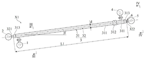
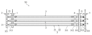
도 1 및 도 2는, 본 발명의 실시형태에 따른 액화 가스용 기화기의 개략구성을 나타내고 있다. 본 실시형태의 액화 가스용 기화기(X1)는, 열매체 공급관(1)과, 액화 가스 공급관(2)과, 각각이 열매체 용기(31) 및 전열관(32)을 가진 복수의 기화 유닛(3)과, 열매체 배출관(4)과, 기화 가스 배출관(5)을 구비하고 있다. 전열관(32)은 열매체 용기(31)와 함께 가로 방향에 설치되어, 수평위치로부터 각도(θ)로 경사진 상태로 설치되어 있다. 또, 이들 도 1 및 도 2에 있어서, 열매체 공급관(1), 액화 가스 공급관(2), 열매체 용기(31), 전열관(32), 열매체 배출관(4), 기화 가스 배출관(5) 등의 두께는 간략화를 위하여 도시 생략하고 있다. 또한, 이하에 있어서는, 기화되는 액화 가스가 액화 천연 가스(LNG)인 것으로서 설명을 진행시킬 경우도 있지만, 본 발명은 이것으로 한정되는 것은 아니다.1 and 2 show a schematic configuration of a vaporizer for liquefied gas according to an embodiment of the present invention. The vaporizer X1 for liquefied gas according to the present embodiment includes a heating
열매체 공급관(1)은, 도시되어 있지 않은 열매체 공급원(온수공급원)으로부터 연장되는 배관에 접속되어 있고, 수평방향으로 연장되고 있다. 열매체 공급관(1)은, 예를 들면, 압력배관용 탄소강 강관(STPG관)에 의해 구성된다.The heating
액화 가스 공급관(2)은, 예를 들면 스테인리스 강철강관(SUSTP관)으로 이루어지고, 예를 들면 LNG 저장조로부터 연장되는 배관에 접속되어 있다. 액화 가스 공급관(2)은, 열매체 공급관(1)이 연장되는 방향과 거의 평행한 수평방향으로 연장되고 있다.The liquefied
복수의 기화 유닛(3)은, 열매체 공급관(1) 및 액화 가스 공급관(2)이 연장되는 방향에 있어서 간격을 두고 병렬로 배치되어 있다. 본 실시형태에서는, 3개의 기화 유닛(3)이 액화 가스 공급 단부에서부터 기화 가스 배출 단부를 향해서 위쪽으로 경사각도(θ)로 나열된 양상을 나타내지만, 기화 유닛(3)의 수는 이것으로 한정되는 것은 아니다. 각 기화 유닛(3)은, 낮은 위치로부터 높은 위치로 연장되는 열매체 용기(31)와, 이 열매체 용기(31)의 내부를 관통하도록 낮은 위치로부터 높은 위치로 연장되는 전열관(32)을 구비한다.The plurality of vaporizing
열매체 용기(31)는, 전체로서 원통 형상을 하고 있고, 수평위치로부터 θ의 경사각도로 낮은 위치 측에서부터 높은 위치 측으로 연장되고 있다. 본 실시형태에서는, 본체부(311)와, 신축부(312)와, 길이방향 양 단부의 캡부(313)를 구비한다. 본체부(311)는 직관 형상이며, 예를 들면 압력배관용 탄소강 강관(STPG관)으로 이루어진다. 신축부(312)는, 본체부(311)보다도 신축되는 부분이며, 예를 들면 본체부(311)의 길이방향의 도중에 삽입된 신축 이음새에 의해서 구성된다. 신축부(312)로서는, 예를 들면 금속제의 벨로즈(bellows)형 신축 이음새를 채용할 수 있다.The
캡부(313)는, 열매체 용기(31)의 길이방향 양 단부에 각각 설치되어 있고, 본체부(311)의 양 단부를 가로막고 있다. 캡부(313)는, 본체부(311)와는 재질이 다른 별개의 부재에 의해서 구성되어 있고, 예를 들면 스테인리스 강철제이다. 캡부(313)는 볼록 형상이 되는 반구면 형상 또는 곡면 형상으로 되어 있다.The
전열관(32)은, 열매체 용기(31) 양 단부의 캡부(313)를 관통하고 있고, 열매체 용기(31)의 내부에 있어서 낮은 위치로부터 높은 위치에 열매체 용기(31)와 마찬가지로 수평위치로부터 θ의 경사각도를 가지고 연장되어 있다. 전열관(32)은, 예를 들면 심리스 직관에 의해 구성되어 있고, 예를 들면 시판의 표준치수 물품의 심리스 스테인리스 강철 강관이 사용된다. 표준치수 물품의 심리스 스테인리스 강철 강관(전열관(32))은, 예를 들면 그 길이가 4m 혹은 6m이며, 직경(내경)이 28.4㎜이다. 또, 열매체 용기(31)를 구성하는 본체부(311)에 대해서도, 예를 들면 시판의 표준치수 물품 강관(압력배관용 탄소강 강관)이 사용된다. 표준치수 물품의 압력배관용 탄소강 강관(본체부(311))은, 예를 들면 그 길이가 4m 혹은 6m이며, 직경(내경)이 80.1㎜이다. 또한, 본 실시형태와 같이 본체부(311)의 도중에 신축부(312)로서의 신축 이음새가 삽입되는 구성에서는, 표준치수 물품의 압력배관용 탄소강 강관을 적당히 절단해서 사용하면 된다.The
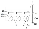
도 3에 나타낸 바와 같이, 열매체 용기(31)의 낮은 위치 측 단부 근방의 부분에는, 해당 열매체 용기(31)의 내부에 열매체를 도입하기 위한 열매체 도입 노즐(34)이 설치되어 있다. 열매체 용기(31)의 길이방향에서 보아서, 열매체 도입 노즐(34)의 중심선(O2)은, 열매체 용기(31)의 중심선(O1)으로부터 시프트된 위치에 있다. 열매체 도입 노즐(34)은, 예를 들면, 열매체 공급관(1)으로부터 분기 형태로 연장되는 열매체용 분기로(11)와 플랜지(34a, 11a)를 개재해서 접속되어 있다. 이러한 구성에 의해, 열매체 공급관(1)과 열매체 용기(31)의 낮은 위치 측 단부 근방의 부분은, 열매체용 분기로(11) 및 열매체 도입 노즐(34)을 개재해서 연통하고 있다.As shown in Fig. 3, a heating
도 1에 나타낸 바와 같이, 전열관(32)의 낮은 위치 측의 액화 가스 공급 단부(321)에는, 액화 가스 공급관(2)으로부터 분기 형태로 연장되는 액화 가스용 분기로(21)가 용접 등에 의해 접속되어 있다. 이러한 구성에 의해, 액화 가스 공급관(2)과 전열관(32)의 액화 가스 공급 단부(321)는, 액화 가스용 분기로(21)를 개재해서 연통하고 있다.1, a liquefied
도 1에 나타낸 바와 같이, 열매체 배출관(4)은, 기화 유닛(3)의 높은 위치 측 단부의 근방에 설치되어 있다. 열매체 배출관(4)은, 열매체 공급관(1)이 연장되는 방향과 거의 평행한 수평방향으로 연장되고 있다. 도 4에 나타낸 바와 같이, 열매체 배출관(4)에는, 복수의 기화 유닛(3) 각각에 대응하는 복수의 열매체 배출용 분기로(41)가 설치되어 있고, 열매체 배출관(4)과 각 열매체 용기(31)의 높은 위치 측 단부 근방의 부분이 열매체 배출용 분기로(41)를 개재해서 연통하고 있다. 열매체 용기(31)의 길이방향에서 보아서, 열매체 배출용 분기로(41)의 중심선(O3)은, 열매체 용기(31)의 중심선(O1)으로부터 시프트된 위치에 있다. 열매체 배출용 분기로(41)는, 예를 들면, 열매체 용기(31)로부터 연장되는 열매체 배출 노즐(314)과 플랜지(41a, 314a)를 개재해서 접속되어 있다. 상기 열매체 도입 노즐(34)을 개재해서 열매체 용기(31) 내에 열매체가 순차 공급되면, 해당 열매체는 열매체 용기(31) 내를 흘러서 회전하면서 이동하고, 열매체 배출용 분기로(41), 열매체 배출관(4)을 개재해서 외부에 배출된다. 외부에 배출된 열매체는, 도시하지 않은 재가열 수단에 의해 재가열되고, 재차 도시하지 않은 열매체 공급원으로 순환된다.As shown in Fig. 1, the heating
도 1에 나타낸 바와 같이, 기화 가스 배출관(5)은, 기화 유닛(3)의 높은 위치 측 단부의 근방에 설치되어 있고, 액화 가스 공급관(2), 열매체 배출관(4)이 연장되는 방향과 거의 평행한 수평방향으로 연장되고 있다. 도 2에 나타낸 바와 같이, 기화 가스 배출관(5)에는, 복수의 기화 유닛(3) 각각에 대응하는 복수의 기화 가스 배출용 분기로(51)가 설치되어 있고, 기화 가스 배출관(5)과 각 전열관(32)의 높은 위치 측의 기화 가스 배출 단부(322)가 기화 가스 배출용 분기로(51)를 개재해서 연통하고 있다.1, the vaporizing
본 실시형태에 있어서, 각 전열관(32)의 기화 가스 배출 단부(322)에는, 스로틀 기구(6)가 부착되어 있다. 도 5는, 도 1 중 스로틀 기구(6)가 부착되어 있는 기화 가스 배출 단부(322) 부근을 확대한 도면이다. 스로틀 기구(6)는, 예를 들면 오리피스로서 구성되어 있고, 스로틀 구멍(6a)를 구비한다. 스로틀 기구(6)(오리피스)는, 기화 가스 배출 단부(322) 및 기화 가스 배출용 분기로(51)의 양쪽의 플랜지(322a, 51a) 사이에 끼워져 있다. 본 실시형태에서는, 3개의 기화 유닛(3)(전열관(32)) 전체에 대해서 동일한 구경 크기의 스로틀 기구(6)(오리피스)가 이용된다. 오리피스의 구경 크기에 대해서는, 3개의 기화 유닛(3)의 각각의 전열관(32)으로부터 기화 가스 배출용 분기로(51)로 유출되는 기화 가스의 양을 균일화하도록 그 구경 크기가 결정될 수 있다. 이러한 스로틀 기구(6)를 구비한 구성에 따르면, 복수의 기화 유닛(3) 사이의 액화 가스의 분산성을 양호하게 하는 동시에, 급격한 유출량을 제한하는 효과도 거둔다.In the present embodiment, a
또한, 도 5는, 오리피스를 플랜지(322a, 51a) 사이에 끼운 상태에서, 전열관(32)의 경사각도(θ)를 두고 기액계면(S1)이 기화 가스 배출 단부(322)로부터 오리피스의 스로틀 구멍(6a)에까지 도달하고 있는 극단적인 상황을 도시하였다. 이와 같이 경사각도(θ)가 작고, 0도에 가까웠다고 해도, 오리피스가 존재함으로써, 액상의 액화 가스의 기화 가스 배출 단부(322)로부터의 튀어나옴을 방지할 수 있다. 도 6은, 스로틀 기구(6)의 부분을 VI-VI 단면으로 도시한 것이다. 도 6에서는, 오리피스(스로틀 기구(6))의 스로틀 구멍(6a)이 전열관(32)의 중심부에 위치하고 있다. 또, 오리피스(스로틀 기구(6))의 스로틀 구멍(6a)에 대해서는, 도 7에 나타낸 바와 같이, 전열관(32)의 중심부에서부터 위쪽으로 시프트된 위치에 형성해도 된다. 도 7에 나타낸 구성에 따르면, 액화 가스가 액상으로 기화 가스 배출 단부(322)에 도달하여도, 그 액화 가스의 배출을 방해하는 효과를 보다 높일 수 있다.5 shows a state in which the gas-liquid interface S1 is moved from the vaporizing
도 8은, 전열관(32)을 수직방향으로 세운 경우의 전열관(32) 내부에서의 기액계면(S1)의 위치를 모식적으로 나타낸 것이다. (d)는 전열관 내경을, (L1)은 전열관(32)에 있어서의 전열부(열매체 용기(31)의 내부를 뻗는 부분)의 길이를 나타내고 있다. (L3)은, 100% 부하에서 증발하고 있을 때의 기액계면(S1)의 길이(전열부의 하단에서 기액계면까지의 치수)을 나타내고 있다. 이 (L3)은 통상 (L1)의 20% 정도로, 증발 부하가 작아지면 짧아진다.8 schematically shows the position of the gas-liquid interface S1 inside the
도 9는 전열관(32)이 경사각도(θ)로 경사진 경우의 기액계면(S1)의 위치를 모식적으로 나타낸 것이다. 경사각도(θ)는 전열관(32) 내에서 증발 기화되는 액화 가스(예를 들면 LNG)의 기액계면(S1)의 위치를 결정하는 각도가 되고, 예를 들면 0도를 초과하여 30도 이하로 설정되고, 바람직하게는 5도 내지 20도로 설정된다. 전열관(32)을 도 8의 수직방향에서 도 9와 같이 경사각도(θ)로 경사지게 해도 평균적인 기액계면의 길이(L3)는 변하지 않지만, 액면 중 전열부의 하단에서부터 가장 멀어지는 위치는, 전열관(32)의 내벽을 따라서 (L4)까지 뻗는 것으로 된다. 이 결과, (L4)가 (L1)에 근접하면 근접할수록 액화 가스(LNG)가 기화 가스 배출 단부(322)로부터 튀어나오기 쉬워진다. 특히 부하가 변동한 경우, 액화 가스가 기세 좋게 기화 가스 배출 단부(322)를 향해서 이동해서 액적이 튀어나오는 현상이 일어나기 쉽다.9 schematically shows the position of the gas-liquid interface S1 when the heat
도 10 및 도 11은, 가로 배치형의 LNG 저장조(X2)(액화 가스 저장조)와, 이 LNG 저장조(X2)의 아래쪽에 설치된 액화 가스용 기화기(X1)를 구비해서 구성된 액화 가스용 기화 시스템(Y)을 나타내고 있다.10 and 11 are schematic diagrams of a vaporizing system for liquefied gas (hereinafter referred to as " vaporized liquefied gas ") comprising a LNG storage tank X2 (liquefied gas storage tank) of a horizontally disposed type and a vaporizer X1 for liquefied gas provided below the LNG storage tank X2 Y).
LNG 저장조(X2)는, 가로배치 원통형이며, 기초부(17) 위에 다리부(16)에 의해 유지된 상태에서 설치된다. 도 11에 잘 나타나 있는 바와 같이, 기초부(17)는, 소정의 간격을 두고서 2군데에 설치된다. LNG 저장조(X2)는, 외부통(12)과 내부통(14)으로 구성되어 있고, 그 간극의 단열층(13)에는 펄라이트(perlite)라고 불리는 SiO2를 주성분으로 하는 분말 형태의 단열재가 충전되어, 3Pa 이하까지 진공 감압된 진공단열층을 형성하고 있다. 액상의 액화 가스(LNG)(15)는, LNG 저장조(X2)의 바닥부로부터 취출되어 단열층(13) 내를 관통하는 배관(7)을 통과하고, 배관(8)을 통과해서 액화 가스용 기화기(X1)의 액화 가스 공급관(2)에 인도된다.The LNG storage tank X2 is disposed in a state of being horizontally disposed in a cylindrical shape and held by the
본 실시형태의 액화 가스용 기화 시스템(Y)에 있어서는, 기화 가스의 수요량, 소비량 등에 따라서, LNG 저장조(X2)의 용량이나 액화 가스용 기화기(X1)의 크기, 기화 유닛(3)의 개수 등이 선택된다.In the vaporizing system for liquefied gas Y according to the present embodiment, the capacity of the LNG storage tank X2, the size of the vaporizer X1 for liquefied gas, the number of vaporizing
이하의 표 1은, LNG 저장조(X2)의 용량을 30㎥로 하고, 액화 가스용 기화기(X1)에 대해서는, 액화 가스의 증발량이 500kg/h가 되도록 1기당 50kg/h의 증발량을 지니는 기화 유닛(3)을 10기 설치했을 경우에 있어서, 전열관(32)의 경사각도(θ)에 따른 각 개소 치수를 나타낸 표이다. 30㎥ 용량의 LNG 저장조(X2)의 크기는, 예를 들면, 직경 2.7m이고 길이가 9.5m이다.The following Table 1 shows the relationship between the evaporation amount of the LNG storage tank X2 and the evaporation amount of the evaporator X1 for liquefied gas of 50 kg / 10 is a table showing the respective spot dimensions according to the inclination angle? Of the

표 1에 있어서, (d)는 전열관(32)의 내경(외경이 34.0㎜)을, (L1)은 4m의 표준치수 물품의 심리스 스테인리스 강철강관(전열관(32))으로 제작한 전열관(32)의 전열부의 길이를, (L2)는 도 11에 나타낸 LNG 저장조(X2)의 기초부(17)의 간격을 각각 나타내고 있다. 또한, (H1)은 도 11에 나타낸 LNG 저장조(X2) 하부의 지상 수준까지의 거리를, (H2)는 도 9에 나타낸 전열관(32)의 경사각도(θ)에 있어서의 전열관(32)의 경사 높이를, (L3)은 도 8에서 나타낸 기액계면까지의 길이를, 도 9에서는 그 평균 길이를 나탸내고 있고, (L4)는 마찬가지로 도 9에서 나타낸 기액계면의 전열관(32)의 내벽을 따른 길이를 각각 나타내고 있다.In Table 1, (d) is a
여기서, 액화 가스용 기화기(X1)를 LNG 저장조(X2)의 아래쪽에 설치하기 위해서는, 액화 가스용 기화기(X1) 전체의 높이가, LNG 저장조(X2) 하부의 지상 수준까지의 거리(H1)보다 짧게 될 필요가 있다. 기화 유닛(3)의 상하부에는 열매체 공급관(1)이나 열매체 배출관(4)이 접속되어 있기 때문에, 액화 가스용 기화기(X1) 전체의 높이는, 전열관(32)의 경사 높이(H2)와, 또한 500 내지 1,000㎜ 정도의 치수가 필요해진다. 따라서, 표 1로부터도 이해되는 바와 같이, 전열관(32)의 경사각도(θ)는 30도 이하(즉, (H2)가 1900㎜ 이하)인 것이 필요해진다. 또한, θ=0도일 때 (L4)가 (L1)과 동등하게 되어, 액화 가스가 기화 가스 배출 단부에서부터 튀어나오기 쉬워지므로, 전열관(32)의 경사각도(θ)는 0도를 초과하고 있는 것도 필요해진다.Here, in order to install the vaporizer X1 for liquefied gas below the LNG storage tank X2, the height of the entire vaporizer X1 for liquefied gas is set to be larger than the height H1 to the ground level below the LNG storage tank X2 It needs to be short. The total height of the vaporizer X1 for the liquefied gas is set to be equal to the sum of the inclined height H2 of the
또, 30㎥ 용량의 LNG 저장조의 크기는, 직경이 2.7m이고 길이가 9.5m이므로, 그 범위에서 기초부(17)의 간격(L2)은 6.0m가 된다. 4m 표준크기의 전열관을 사용한 기화 유닛(1기당의 폭은 250㎜, 길이는 4.3m)을 10기 짜넣으면, 2.5m 폭×4.3m 길이가 되고, LNG 저장조(X2)와 조합시켜서 해당 LNG 저장조(X2)의 아래쪽에 설치할 수 있다. 또한, LNG 저장조(X2) 하부의 지상 수준까지의 거리(H1)는, 액화 가스용 기화 시스템(Y)의 전체 높이를 예를 들면 5.5m 이하로 하고자 할 경우에는, H1 = 5.5m-2.7m = 2.8m가 되므로, 열매체 공급관(1)이나 열매체 배출관(4)의 설치를 위한 치수를 빼면, 전열관(32)의 경사 높이(H2)가 2.0m 이하이면 설비화는 충분히 가능하다.Since the LNG storage tank having a capacity of 30
이하의 표 2는, LNG 저장조(X2)의 용량을 50㎥로 하고, 액화 가스용 기화기(X1)에 대해서는, 액화 가스의 증발량이 750kg/h가 되도록 1기당 75kg/h의 증발량을 지니는 기화 유닛(3)을 10기 설치한 경우에 있어서, 전열관(32)의 경사각도(θ)에 따른 각 개소 치수를 나타낸 표이다. 50㎥ 용량의 LNG 저장조(X2)의 크기는, 예를 들면, 직경 2.9m이고 길이가 13.0m이다.The following Table 2 shows the relationship between the evaporation amount of the LNG storage tank X2 and the evaporation amount of the evaporator X1 for the liquefied gas of 75 kg / 10 is a table showing the respective spot dimensions according to the inclination angle [theta] of the

도 13에 나타낸 표에 있어서, (d)는 전열관(32)의 내경(외경이 34.0㎜)을, (L1)은 6m의 표준치수 물품의 심리스 스테인리스 강철강관(전열관(32))으로 제작한 전열관(32)의 전열부의 길이를, (L2)는 도 11에 나타낸 LNG 저장조(X2)의 기초부(17)의 간격을 각각 나타내고 있다. 또한, (H1)은 도 11에 나타낸 LNG 저장조(X2)하부의 지상 수준까지의 거리를, (H2)는 도 9에 나타낸 전열관(32)의 경사각도(θ)에 있어서의 전열관(32)의 경사 높이를, (L3)은 도 8에 나타낸 기액계면까지의 길이를, 도 9에서는 그 평균 길이를 나타내고 있고, (L4)는 마찬가지로 도 9에 나타낸 기액계면의 전열관(32)의 내벽을 따른 길이를 각각 나타내고 있다.13, (d) shows the inner diameter of the heat transfer pipe 32 (outer diameter is 34.0 mm) and (L1) is the heat transfer pipe made of a seamless stainless steel steel pipe (heat transfer pipe 32) (L2) indicates the distance between the
여기서, 액화 가스용 기화기(X1)를 LNG 저장조(X2)의 아래쪽에 설치하기 위해서는, 액화 가스용 기화기(X1) 전체의 높이가, LNG 저장조(X2) 하부의 지상 수준까지의 거리(H1)보다 짧게 될 필요가 있다. 기화 유닛(3)의 상하부에는 열매체 공급관(1)이나 열매체 배출관(4)이 접속되어 있기 때문에, 액화 가스용 기화기(X1) 전체의 높이는, 전열관(32)의 경사 높이(H2)와, 또한 500 내지 1,000㎜ 정도의 치수가 필요로 된다. 따라서, 도 13으로부터도 이해되는 바와 같이, 전열관(32)의 경사각도(θ)는 20도 이하(즉, (H2)가 1984㎜ 이하)인 것이 필요해진다. 또한, θ=0도일 때 (L4)가 (L1)과 동등하게 되어, 액화 가스가 기화 가스 배출 단부에서부터 튀어나오기 쉬워지므로, 전열관(32)의 경사각도(θ)는 0도를 초과하고 있는 것도 필요해진다.Here, in order to install the vaporizer X1 for liquefied gas below the LNG storage tank X2, the height of the entire vaporizer X1 for liquefied gas is set to be larger than the height H1 to the ground level below the LNG storage tank X2 It needs to be short. The total height of the vaporizer X1 for the liquefied gas is set to be equal to the sum of the inclined height H2 of the
또, 50㎥ 용량의 LNG 저장조의 크기는, 직경이 2.9m이고 길이가 13.0m이므로, 그 범위에서 기초부(17)의 간격(L2)은 8.0m가 된다. 6m 표준크기의 전열관을 사용한 기화 유닛(1기당의 폭은 250㎜, 길이는 6.3m)을 10기 짜넣으면, 2.5m 폭×6.3m 길이가 되고, LNG 저장조(X2)와 조합시켜서 해당 LNG 저장조(X2)의 아래쪽에 설치할 수 있다. 또한, LNG 저장조(X2) 하부의 지상 수준까지의 거리(H1)는, 액화 가스용 기화 시스템(Y)의 전체높이를 예를 들면 5.5m 이하로 하고자 할 경우에는, H1 = 5.5m-2.9m = 2.6m가 되므로, 열매체 공급관(1)이나 열매체 배출관(4)의 설치를 위한 치수를 빼면, 전열관(32)의 경사 높이(H2)가 2.0m 이하이면 설비화는 충분히 가능하다.The size of the LNG storage tank having a capacity of 50
도 10 및 도 11에 나타낸 액화 가스용 기화 시스템(Y)에 있어서는, 가로 배치형의 LNG 저장조(X2)의 아래쪽에 액화 가스용 기화기(X1)를 바로 근처의 거리가 되도록 설치할 수 있다. 또한, 도 11로부터 이해되는 바와 같이, LNG 저장조(X2)의 하부의 지면(2군데의 기초부(17) 사이)을 파내려가면, 기초부(17)의 높이(액화 가스용 기화 시스템(Y) 전체의 지상 수준으로부터의 높이)가 커지는 것을 회피하면서, LNG 저장조(X2) 하부의 거리(H2)를 크게 할 수 있다. 이것에 의해, 액화 가스용 기화기(X1) 및 LNG 저장조(X2)를 포함하는 액화 가스용 기화 시스템(Y) 전체를 컴팩트하게 설치할 수 있다.In the vaporizing system (Y) for liquefied gas shown in Figs. 10 and 11, the vaporizer X1 for the liquefied gas can be provided at a position near the horizontal position of the LNG storage tank X2. 11, when the ground surface (between the two base portions 17) of the LNG storage tank X2 is digged, the height of the base portion 17 (the vaporization system for the liquefied gas Y The height H2 from the ground level of the entire LNG storage tank X2 can be avoided while the distance H2 under the LNG storage tank X2 can be increased. As a result, the entire vaporizing system Y for the liquefied gas including the vaporizer X1 for liquefied gas and the LNG storage tank X2 can be compactly installed.
또한, 가로 배치형의 LNG 저장조(X2)의 아래쪽에 설치되는 액화 가스용 기화기(X1)에 대해서는, 해당 LNG 저장조(X2)의 바로 아래에서의 가로방향(도 10에 있어서의 좌우 방향 및 도 11에 있어서의 지면의 수직방향)에 있어서, 양 사이드에 충분한 공간이 있으므로, 상기 가로방향에 있어서 기화 유닛(3)의 설치수를 늘릴 수 있다. 표 1 및 표 2를 참조해서 전술한 바와 같이, 기화 유닛(3)을 10기 나열할 경우에 있어서, 액화 가스용 기화기(X1) 전체의 폭은 2.5m이며, LNG 저장조의 직경은 2.7m또는 2.9m이므로, 평면에서 보아서 LNG 저장조(X2)로부터 액화 가스용 기화기(X1)가 비어져 나오는 일 없이, 컴팩트하게 설치할 수 있다.Further, the vaporizer X1 for the liquefied gas installed below the horizontal arrangement type LNG storage tank X2 is arranged in the lateral direction (the left-right direction in FIG. 10 and the left-right direction in FIG. (The vertical direction of the paper surface of the vaporization unit 3), the number of
도 11에 나타낸 배관(8)은, LNG 저장조(X2)의 바로 아래에 있어서 짧은 거리에서 액화 가스용 기화기(X1)에 접속되어 있다. 이러한 구성에 따르면, 액화 가스가 액화 가스용 기화기(X1)에 도달할 때까지의 압력손실을 작게 억제할 수 있다.The piping 8 shown in Fig. 11 is connected to the vaporizer X1 for liquefied gas at a short distance just below the LNG storage tank X2. According to this configuration, the pressure loss until the liquefied gas reaches the vaporizer X1 for the liquefied gas can be suppressed to be small.
액화 가스용 기화기(X1)는 복수의 기화 유닛(3)(예를 들면 10기)으로 구성되어 있고, 전열관(32)의 경사각도(θ)는, 액화 가스 공급 단부(321)로부터 기화 가스 배출 단부(322)를 향해서 0도를 초과하여 30도 이하로 하고, 바람직하게는 5도로부터 20도의 범위에서 경사진다. 이러한 구성에 따르면, 기화 가스 배출 단부(322)로부터 액화 가스(LNG 액체)를 튀어나오지 않도록 할 수 있고, 설비화는 충분히 가능하다.The inclined angle θ of the
상기 구성의 액화 가스용 기화 시스템(Y)의 가동 시에는, 액화 가스용 기화기(X1)에 있어서는, 액화 가스 공급관, 액화 가스용 분기로(21)를 개재해서 전열관(32) 내에 액화 가스가 순차 공급되면, 해당 액화 가스는 열매체 용기(31)의 내부를 관통하는 전열관(32) 내를 흐르는 과정에서 열매체와의 열교환에 의해 기액계면을 형성하면서 순차 기화되어 가스로 된다. 전열관(32) 내에서 완전히 기화된 가스는, 기화 가스 배출용 분기로(51)를 개재해서 기화 가스 배출관(5)에서 집합되어, 배관(9)(도 11 참조)을 통해서 천연 가스 이용 현장에 보내진다.In the vaporizer X1 for a liquefied gas, the liquefied gas is sequentially introduced into the
도 11에 나타낸 바와 같이, 열매체 공급관(1)에는 배관(10)이 접속되어 있고, 열매체 배출관(4)에는 배관(18)이 접속되어 있다. 열매체로서의 예를 들면 40℃ 전후의 온수가, 배관(10)을 통해서 보내져, 열매체 공급관(1)으로부터 각 기화 유닛(3)의 열매체 도입 노즐(34)을 개재해서, 분배되어 열매체 용기(31) 내에 공급된다. 공급된 온수는, 열매체 용기(31) 내를 회전하면서 흘러서, 전열관(32) 내의 LNG와의 사이에서 열교환을 행하고, 열매체 배출용 분기로(41), 열매체 배출관(4)을 개재해서 배관(18)을 통해서 배출된다.As shown in Fig. 11, a
액화 가스 공급관(2)을 개재해서 각 기화 유닛(3)의 전열관(32)에는, -160 내지 -140℃ 정도의 저온액체인 LNG가 분배되어 공급된다. 공급된 LNG는, 전열관(32)을 개재해서 온수에 의해서 가열 기화되고, 전열관(32)은 직관인 채로 0℃ 이상이고 최고 40℃ 부근까지 온도 상승한다. 전열관(32)은 스테인리스 강철로 만든 제품이므로, 100℃의 온도차에 의해서 1m당 1.5㎜의 신축량의 차이가 생긴다. 열매체 용기(31)는, 압력배관용 탄소강 강관(STPG관)으로 구성되므로, 100℃의 온도차에 의해 1m당 1.2㎜의 신축량의 차이가 생긴다. 또한, 전열관(32) 내를 흐르는 LNG가 기화할 때의 온도 변화는 상대적으로 크고, 열매체 용기(31) 내를 흐르는 온수의 온도변화는 상대적으로 작으므로, 전열관(32)과 열매체 용기(31) 사이에서 온도차의 차이가 크다. 이러한 것이 맞물려, 예를 들면 액화 가스용 기화기(X1)를 간헐 운전하면, 전열관(32)의 신축량이 열매체 용기(31)의 신축량에 비해서 커진다.LNG, which is a low-temperature liquid of about -160 to -140 DEG C, is distributed and supplied to the
본 실시형태에서는, 전열관(32)이 이음매 없는 직관에 의해 구성되어 있으므로, 전열관(32) 자체에 가공 왜곡이 생기지 않아, 전열관(32)에 대해서 가열 및 냉각이 반복되어도 열피로가 생기기 어렵다.In the present embodiment, since the
또한, 전열관(32)이 온도변화에 따라서 신축되어도, 이 전열관(32)의 외측을 둘러싸는 동시에 양 단부를 지지하는 열매체 용기(31)에 있어서, 본체부(311)보다도 신축되는 신축부(312)가 설치되어 있으므로, 이 신축부(312)에 의해 전열관(32)의 신축을 흡수할 수 있다. 따라서, 전열관(32)과 열매체 용기(31)의 접합부 혹은 전열관(32) 자체에 반복해서 큰 응력이 작용하는 것을 회피할 수 있다. 또, 도 1 및 도 2에서는 신축부(312)로서의 신축 이음새를 1군데에 설치하는 예를 나타냈지만, 이간하는 복수 개소에 신축부(312)를 설치해도 된다. 또한, 신축 이음새의 형식에 대해서도, 벨로즈형 신축 이음새로 한정되는 것은 아니다.The
이상, 본 발명의 실시형태에 대해서 설명했지만, 본 발명은 그 기본사상으로부터 일탈하지 않는 범위에서 다양하게 변형할 수 있다. 예를 들면, 도 1, 도 2 등에 나타낸 상기 실시형태에서는, 전열관(32) 등의 소재를 스테인리스 강철로 만든 제품으로 했지만, 경량화가 요망될 경우에는 알루미늄이나 알루미늄 합금으로 구성할 수도 있다. 또한, 도시한 실시형태에서는, 1개의 기화 유닛(3)에 대해서 각각 1개의 전열관(32)을 이용하고 있지만, 복수의 직관(전열관(32))을 1개의 열매체 용기(31)에 각각 관통시켜, 서로 간섭하지 않도록 설치해도 된다.Although the embodiments of the present invention have been described, the present invention can be modified in various ways without departing from the basic idea thereof. For example, in the above-described embodiment shown in Figs. 1, 2, and the like, the material of the
도 10 및 도 11에 나타낸 상기 실시형태에서는, LNG 저장조(X2)의 하부의 2군데의 기초부(17) 사이의 지면을 파내려가면, LNG 저장조(X2) 하부의 지상 수준까지의 거리(H1)는 동일한 채로도 액화 가스용 기화기(X1)와 LNG 저장조(X2)의 조합 위치 수준을 낮출 수 있으므로, LNG 공급 설비(액화 가스용 기화 시스템(Y))로서의 전체 높이를 더욱 낮출 수 있다. 또한, LNG 저장조(X2)의 용량이나 액화 가스용 기화기(X1)의 증발 기화 가스량의 크기는 공급 설비로서 2분할이나 3분할로 하면 반송 설치에 의해 컴팩트성이 생기므로, 본 발명은 보다 효과적으로 된다.In the embodiment shown in Figs. 10 and 11, when the ground between two
본 발명의 액화 가스용 기화기는, LNG의 기화뿐만 아니라, 비점이 -183℃인 액화 산소, -186℃인 액화 아르곤, -196℃인 액화 질소, -42℃인 프로판 등을 액상으로 저온저장된 액화 가스를 기화시킬 경우에도 적용할 수 있는 것이다.The vaporizer for liquefied gas of the present invention is not limited to the vaporization of LNG, but also includes liquefied oxygen having a boiling point of -183 DEG C, liquefied argon having a boiling point of -186 DEG C, liquefied nitrogen having a boiling point of -196 DEG C, propane having a boiling point of -42 DEG C, It can also be applied when gas is vaporized.
액화 가스의 저장과 소비를 반복하기 위해서 설치되는 공급 설비(액화 가스용 기화 시스템)는, 액화 가스를 저장하는 저장조와 기화기의 조합이 된다. 공급 설비를 공장이나 병원에 설치할 때, 제작 공장에서 제작하여, 트럭으로 반송하고, 설치 장소에 레커에 매달아, 기초부 위에 설치할 때, 상기 실시형태와 같이 제작 공장에서 출하 전에 저장조와 기화기를 가로형으로 해서 컴팩트하게 일체화해서 조립해둘 수 있으면, 트럭에서의 반송이 용이해지는 동시에, 레커에서의 매달기 수준이 낮아진다. 이 때문에, 안정성이 높은 공사를 할 수 있고, 이미 조립이 종료되어 있으므로 최소한의 공사 시공 비용으로 공급 설비를 설치할 수 있다.A supply facility (vaporization system for liquefied gas) installed to repeat the storage and consumption of the liquefied gas is a combination of a storage tank for storing the liquefied gas and a vaporizer. When the supply facility is installed in a plant or a hospital, it is produced in a production factory, is transported in a truck, is hung on a laker at a place of installation, and is installed on a base, the storage tank and the vaporizer are horizontally So that it can be easily transported in a truck, and the level of hanging at the laker is lowered. Therefore, highly reliable construction can be performed, and since the assembly is already finished, the supply facility can be installed with the minimum construction cost.
또한, 공급 설비가 설치되는 공장이나 병원 등에서는, 공급 설비의 높이가 높을 경우, 고압 가스 보안법에 의거하는 공급 설비의 검사나 유지를 위한 고소작업용 데크가 필요해진다. 상기 실시형태에 있어서는, 공급 설비의 높이가 낮게 억제되어 있으므로 고소작업용 데크가 불필요해지고, 설비 비용도 포함시켜서 검사 및 유지에 드는 비용이 저렴해지는 효과가 있다.Also, in a factory or a hospital where a supply facility is installed, when the height of the supply facility is high, a deck for high-altitude work is required for inspection and maintenance of the supply facility based on the high-pressure gas security law. In the above embodiment, since the elevation of the supply facility is suppressed to a low level, the elevation work deck becomes unnecessary, and the cost for inspection and maintenance including the facility cost is reduced.
X1: 액화 가스용 기화기
X2: LNG 저장조(액화 가스 저장조)
Y: 액화 가스용 기화 시스템
1: 열매체 공급관
11: 열매체용 분기로
11a: 플랜지
2: 액화 가스 공급관
21: 액화 가스용 분기로
3: 기화 유닛
31: 열매체 용기
34a: 플랜지
51a: 플랜지
311: 본체부
312: 신축부
313: 캡부
314: 열매체 배출 노즐
314a: 플랜지
32: 전열관
321: 액화 가스 공급 단부
322: 기화 가스 배출 단부
34: 열매체 도입 노즐
4: 열매체 배출관
41: 열매체 배출용 분기로
5: 기화 가스 배출관
51: 기화 가스 배출용 분기로
6: 스로틀 기구
6a: 스로틀 구멍
7, 8, 9, 10, 18: 배관
12: 외부통
13: 단열층
14: 내부통
15: LNG 액체
16: 다리부
17: 기초부
H1: LNG 저장조 하부의 지상 수준까지의 거리
H2: 전열관의 경사 높이
L1: 전열부의 길이
L2: 기초부의 간격
L3: 기액계면의 길이
L4: 액면이 내벽을 따른 길이
θ: 전열관의 경사각도
S1: 기액계면X1: Vaporizer for liquefied gas X2: LNG storage tank (liquefied gas storage tank)
Y: Vaporization system for liquefied gas 1: Heat medium supply pipe
11: branch for
2: liquefied gas supply pipe 21: branch pipe for liquefied gas
3: vaporizing unit 31: heating medium container
34a:
311: main body 312: stretchable portion
313: Cap part 314: Heat medium discharge nozzle
314a: flange 32: heat transfer pipe
321: liquefied gas supply end 322: vaporized gas discharge end
34: heating medium introduction nozzle 4: heating medium outlet pipe
41: branch pipe for heating medium discharge 5: vaporized gas discharge pipe
51: branch line for exhausting gas 6: throttle mechanism
6a: throttle holes 7, 8, 9, 10, 18: piping
12: outer cylinder 13: insulating layer
14: inner cylinder 15: LNG liquid
16: leg portion 17: base portion
H1: Distance to the ground level below the LNG storage tank
H2: inclination height of the heat transfer pipe L1: length of the heat transfer portion
L2: interval of base portion L3: length of vapor-liquid interface
L4: Length along the inner wall of the liquid surface θ: Tilt angle of the heat transfer pipe
S1: gas-liquid interface
Claims (9)
열매체가 보충 가능하게 수용되는 열매체 용기와, 심리스 직관에 의해 구성되어, 상기 열매체 용기의 내부를 관통하는 동시에 해당 열매체 용기에 지지되는 전열관을 포함하되,
상기 전열관은, 액화 가스 공급 단부와, 해당 액화 가스 공급 단부보다도 높은 위치에 있는 기화 가스 배출 단부를 구비하고, 수평위치로부터 경사진 상태로 설치되는, 액화 가스용 기화기.A vaporizer for liquefied gas which vaporizes a liquefied gas by heating,
And a heat transfer pipe which is formed by a seamless straight pipe and passes through the inside of the heating medium container and is supported by the heating medium container,
Wherein the heat transfer pipe has a liquefied gas supply end and a vaporization gas discharge end located at a higher position than the liquefied gas supply end and is installed inclined from a horizontal position.
상기 액화 가스 저장조로부터 취출된 액화 가스가 상기 전열관의 낮은 위치 측에 있는 상기 액화 가스 공급 단부로부터 도입되는, 액화 가스용 기화 시스템.A liquefied gas storage vessel of a horizontal arrangement type and a vaporizer for liquefied gas according to any one of claims 1 to 9 provided below the liquefied gas storage tank,
And the liquefied gas taken out from the liquefied gas storage tank is introduced from the liquefied gas supply end located on the lower position side of the heat transfer tube.
Applications Claiming Priority (2)
| Application Number | Priority Date | Filing Date | Title |
|---|---|---|---|
| JPJP-P-2015-212968 | 2015-10-29 | ||
| JP2015212968A JP6633888B2 (en) | 2015-10-29 | 2015-10-29 | Liquefied gas vaporizer and liquefied gas vaporization system |
Publications (1)
| Publication Number | Publication Date |
|---|---|
| KR20170051292A true KR20170051292A (en) | 2017-05-11 |
Family
ID=58710667
Family Applications (1)
| Application Number | Title | Priority Date | Filing Date |
|---|---|---|---|
| KR1020160139497A KR20170051292A (en) | 2015-10-29 | 2016-10-25 | Vaporizer for liquified gas, and vaporization system for liquified gas |
Country Status (3)
| Country | Link |
|---|---|
| JP (1) | JP6633888B2 (en) |
| KR (1) | KR20170051292A (en) |
| TW (1) | TW201730481A (en) |
Cited By (1)
| Publication number | Priority date | Publication date | Assignee | Title |
|---|---|---|---|---|
| WO2021170165A1 (en) * | 2020-02-29 | 2021-09-02 | REGASCOLD GmbH | Heat exchanger for the recovery of refrigeration capacity from the regasification of cryogenic liquefied gases |
Family Cites Families (9)
| Publication number | Priority date | Publication date | Assignee | Title |
|---|---|---|---|---|
| JPS535207A (en) * | 1976-07-05 | 1978-01-18 | Osaka Gas Co Ltd | Vaporizer of liquefied natural gas |
| JPS5955271U (en) * | 1982-09-28 | 1984-04-11 | 石川島播磨重工業株式会社 | Shell-and-tube heat exchanger |
| JP2741935B2 (en) * | 1990-02-01 | 1998-04-22 | 大阪ガスエンジニアリング株式会社 | Low temperature liquefied gas vaporizer |
| JPH05196792A (en) * | 1992-01-21 | 1993-08-06 | Toshiba Corp | Piping device for reactor installation |
| JPH06174194A (en) * | 1992-12-09 | 1994-06-24 | Ishikawajima Harima Heavy Ind Co Ltd | Lpg evaporator |
| JP2000088192A (en) * | 1998-07-17 | 2000-03-31 | Ito Koki Kk | Bulk vessel |
| JP2000146090A (en) * | 1998-11-06 | 2000-05-26 | Kobe Steel Ltd | Air temperature type carburator for low temperature liquefied gas |
| JP2000266477A (en) * | 1999-03-16 | 2000-09-29 | Nippon Shokubai Co Ltd | Method for restraining polymerization in multitubular heat exchanger |
| JP3945252B2 (en) * | 2002-01-10 | 2007-07-18 | 株式会社デンソー | Gas-liquid separator for ejector cycle |
-
2015
- 2015-10-29 JP JP2015212968A patent/JP6633888B2/en not_active Expired - Fee Related
-
2016
- 2016-10-14 TW TW105133178A patent/TW201730481A/en unknown
- 2016-10-25 KR KR1020160139497A patent/KR20170051292A/en unknown
Cited By (1)
| Publication number | Priority date | Publication date | Assignee | Title |
|---|---|---|---|---|
| WO2021170165A1 (en) * | 2020-02-29 | 2021-09-02 | REGASCOLD GmbH | Heat exchanger for the recovery of refrigeration capacity from the regasification of cryogenic liquefied gases |
Also Published As
| Publication number | Publication date |
|---|---|
| JP6633888B2 (en) | 2020-01-22 |
| TW201730481A (en) | 2017-09-01 |
| JP2017082938A (en) | 2017-05-18 |
Similar Documents
| Publication | Publication Date | Title |
|---|---|---|
| JP6684789B2 (en) | Device and method for cooling a liquefied gas | |
| EP2672213B1 (en) | Gasification device for low-temperature liquefied gas | |
| CA2633928A1 (en) | Enhanced lng regas | |
| KR20130133299A (en) | Boil-off gas processing device and liquefied gas tank | |
| KR102036421B1 (en) | Lng tank and system for connecting at least one pipe between an lng tank and a tank connection space thereof | |
| US10775080B2 (en) | LNG gasification systems and methods | |
| KR101868198B1 (en) | Vaporizer for liquefied gas | |
| KR20170051292A (en) | Vaporizer for liquified gas, and vaporization system for liquified gas | |
| JP2011001993A (en) | Liquefied hydrogen storage supply equipment | |
| JP6668180B2 (en) | Vaporizer | |
| JP2007247797A (en) | Lng vaporizer | |
| US20130327404A1 (en) | Method for efficiently delivering liquid argon to a furnace | |
| CN104428619A (en) | Apparatus and method for heating liquefied stream | |
| JP2009127813A (en) | Hydrogen gas supply method and hydrogen gas supply installation | |
| WO2015045992A1 (en) | Liquefied gas vaporization system and liquefied gas vaporization method | |
| JP6928486B2 (en) | Outgassing system | |
| JP6126569B2 (en) | Vaporizer for liquefied gas | |
| JP2011052744A (en) | Air temperature type liquefied gas vaporizer | |
| KR101751841B1 (en) | Leakage Liquefied Gas of Storage Tank Treatment System and Method | |
| JPH0717467A (en) | Device for evaporating leaked cargo | |
| KR102393102B1 (en) | Boil-of-rate reduction system for lng cargo | |
| EP3710743B1 (en) | Cryogenic fluid vaporizer | |
| KR20200008430A (en) | collecting apparatus of leakage for liquid gas storage tank and ship having the same | |
| KR20160115246A (en) | BOG Re-liquefaction Apparatus and Method for Vessel | |
| KR20170010199A (en) | Test storage tank |