KR20170044609A - Exhaust gas treatment device and waste water treatment method for exhaust gas treatment device - Google Patents
Exhaust gas treatment device and waste water treatment method for exhaust gas treatment device Download PDFInfo
- Publication number
- KR20170044609A KR20170044609A KR1020167022713A KR20167022713A KR20170044609A KR 20170044609 A KR20170044609 A KR 20170044609A KR 1020167022713 A KR1020167022713 A KR 1020167022713A KR 20167022713 A KR20167022713 A KR 20167022713A KR 20170044609 A KR20170044609 A KR 20170044609A
- Authority
- KR
- South Korea
- Prior art keywords
- exhaust gas
- scrubber
- seawater
- measuring
- water
- Prior art date
Links
Images


Classifications
-
- B—PERFORMING OPERATIONS; TRANSPORTING
- B01—PHYSICAL OR CHEMICAL PROCESSES OR APPARATUS IN GENERAL
- B01D—SEPARATION
- B01D53/00—Separation of gases or vapours; Recovering vapours of volatile solvents from gases; Chemical or biological purification of waste gases, e.g. engine exhaust gases, smoke, fumes, flue gases, aerosols
- B01D53/34—Chemical or biological purification of waste gases
- B01D53/46—Removing components of defined structure
- B01D53/48—Sulfur compounds
- B01D53/50—Sulfur oxides
- B01D53/501—Sulfur oxides by treating the gases with a solution or a suspension of an alkali or earth-alkali or ammonium compound
- B01D53/502—Sulfur oxides by treating the gases with a solution or a suspension of an alkali or earth-alkali or ammonium compound characterised by a specific solution or suspension
-
- B—PERFORMING OPERATIONS; TRANSPORTING
- B01—PHYSICAL OR CHEMICAL PROCESSES OR APPARATUS IN GENERAL
- B01D—SEPARATION
- B01D53/00—Separation of gases or vapours; Recovering vapours of volatile solvents from gases; Chemical or biological purification of waste gases, e.g. engine exhaust gases, smoke, fumes, flue gases, aerosols
- B01D53/34—Chemical or biological purification of waste gases
- B01D53/346—Controlling the process
-
- B—PERFORMING OPERATIONS; TRANSPORTING
- B01—PHYSICAL OR CHEMICAL PROCESSES OR APPARATUS IN GENERAL
- B01D—SEPARATION
- B01D53/00—Separation of gases or vapours; Recovering vapours of volatile solvents from gases; Chemical or biological purification of waste gases, e.g. engine exhaust gases, smoke, fumes, flue gases, aerosols
- B01D53/34—Chemical or biological purification of waste gases
- B01D53/46—Removing components of defined structure
- B01D53/48—Sulfur compounds
- B01D53/50—Sulfur oxides
- B01D53/501—Sulfur oxides by treating the gases with a solution or a suspension of an alkali or earth-alkali or ammonium compound
- B01D53/504—Sulfur oxides by treating the gases with a solution or a suspension of an alkali or earth-alkali or ammonium compound characterised by a specific device
-
- B—PERFORMING OPERATIONS; TRANSPORTING
- B01—PHYSICAL OR CHEMICAL PROCESSES OR APPARATUS IN GENERAL
- B01D—SEPARATION
- B01D53/00—Separation of gases or vapours; Recovering vapours of volatile solvents from gases; Chemical or biological purification of waste gases, e.g. engine exhaust gases, smoke, fumes, flue gases, aerosols
- B01D53/34—Chemical or biological purification of waste gases
- B01D53/73—After-treatment of removed components
-
- B—PERFORMING OPERATIONS; TRANSPORTING
- B01—PHYSICAL OR CHEMICAL PROCESSES OR APPARATUS IN GENERAL
- B01D—SEPARATION
- B01D53/00—Separation of gases or vapours; Recovering vapours of volatile solvents from gases; Chemical or biological purification of waste gases, e.g. engine exhaust gases, smoke, fumes, flue gases, aerosols
- B01D53/34—Chemical or biological purification of waste gases
- B01D53/92—Chemical or biological purification of waste gases of engine exhaust gases
-
- C—CHEMISTRY; METALLURGY
- C02—TREATMENT OF WATER, WASTE WATER, SEWAGE, OR SLUDGE
- C02F—TREATMENT OF WATER, WASTE WATER, SEWAGE, OR SLUDGE
- C02F1/00—Treatment of water, waste water, or sewage
- C02F1/008—Control or steering systems not provided for elsewhere in subclass C02F
-
- C—CHEMISTRY; METALLURGY
- C02—TREATMENT OF WATER, WASTE WATER, SEWAGE, OR SLUDGE
- C02F—TREATMENT OF WATER, WASTE WATER, SEWAGE, OR SLUDGE
- C02F1/00—Treatment of water, waste water, or sewage
- C02F1/66—Treatment of water, waste water, or sewage by neutralisation; pH adjustment
-
- C—CHEMISTRY; METALLURGY
- C02—TREATMENT OF WATER, WASTE WATER, SEWAGE, OR SLUDGE
- C02F—TREATMENT OF WATER, WASTE WATER, SEWAGE, OR SLUDGE
- C02F1/00—Treatment of water, waste water, or sewage
- C02F1/68—Treatment of water, waste water, or sewage by addition of specified substances, e.g. trace elements, for ameliorating potable water
- C02F1/685—Devices for dosing the additives
- C02F1/686—Devices for dosing liquid additives
-
- C—CHEMISTRY; METALLURGY
- C02—TREATMENT OF WATER, WASTE WATER, SEWAGE, OR SLUDGE
- C02F—TREATMENT OF WATER, WASTE WATER, SEWAGE, OR SLUDGE
- C02F1/00—Treatment of water, waste water, or sewage
- C02F1/72—Treatment of water, waste water, or sewage by oxidation
- C02F1/74—Treatment of water, waste water, or sewage by oxidation with air
-
- B—PERFORMING OPERATIONS; TRANSPORTING
- B01—PHYSICAL OR CHEMICAL PROCESSES OR APPARATUS IN GENERAL
- B01D—SEPARATION
- B01D2251/00—Reactants
- B01D2251/30—Alkali metal compounds
- B01D2251/304—Alkali metal compounds of sodium
-
- B—PERFORMING OPERATIONS; TRANSPORTING
- B01—PHYSICAL OR CHEMICAL PROCESSES OR APPARATUS IN GENERAL
- B01D—SEPARATION
- B01D2251/00—Reactants
- B01D2251/40—Alkaline earth metal or magnesium compounds
- B01D2251/402—Alkaline earth metal or magnesium compounds of magnesium
-
- B—PERFORMING OPERATIONS; TRANSPORTING
- B01—PHYSICAL OR CHEMICAL PROCESSES OR APPARATUS IN GENERAL
- B01D—SEPARATION
- B01D2251/00—Reactants
- B01D2251/40—Alkaline earth metal or magnesium compounds
- B01D2251/404—Alkaline earth metal or magnesium compounds of calcium
-
- B—PERFORMING OPERATIONS; TRANSPORTING
- B01—PHYSICAL OR CHEMICAL PROCESSES OR APPARATUS IN GENERAL
- B01D—SEPARATION
- B01D2251/00—Reactants
- B01D2251/60—Inorganic bases or salts
- B01D2251/604—Hydroxides
-
- B—PERFORMING OPERATIONS; TRANSPORTING
- B01—PHYSICAL OR CHEMICAL PROCESSES OR APPARATUS IN GENERAL
- B01D—SEPARATION
- B01D2251/00—Reactants
- B01D2251/60—Inorganic bases or salts
- B01D2251/606—Carbonates
-
- B—PERFORMING OPERATIONS; TRANSPORTING
- B01—PHYSICAL OR CHEMICAL PROCESSES OR APPARATUS IN GENERAL
- B01D—SEPARATION
- B01D2252/00—Absorbents, i.e. solvents and liquid materials for gas absorption
- B01D2252/10—Inorganic absorbents
- B01D2252/103—Water
- B01D2252/1035—Sea water
-
- B—PERFORMING OPERATIONS; TRANSPORTING
- B01—PHYSICAL OR CHEMICAL PROCESSES OR APPARATUS IN GENERAL
- B01D—SEPARATION
- B01D2259/00—Type of treatment
- B01D2259/45—Gas separation or purification devices adapted for specific applications
- B01D2259/4566—Gas separation or purification devices adapted for specific applications for use in transportation means
-
- C—CHEMISTRY; METALLURGY
- C02—TREATMENT OF WATER, WASTE WATER, SEWAGE, OR SLUDGE
- C02F—TREATMENT OF WATER, WASTE WATER, SEWAGE, OR SLUDGE
- C02F2103/00—Nature of the water, waste water, sewage or sludge to be treated
- C02F2103/18—Nature of the water, waste water, sewage or sludge to be treated from the purification of gaseous effluents
-
- C—CHEMISTRY; METALLURGY
- C02—TREATMENT OF WATER, WASTE WATER, SEWAGE, OR SLUDGE
- C02F—TREATMENT OF WATER, WASTE WATER, SEWAGE, OR SLUDGE
- C02F2103/00—Nature of the water, waste water, sewage or sludge to be treated
- C02F2103/34—Nature of the water, waste water, sewage or sludge to be treated from industrial activities not provided for in groups C02F2103/12 - C02F2103/32
-
- C—CHEMISTRY; METALLURGY
- C02—TREATMENT OF WATER, WASTE WATER, SEWAGE, OR SLUDGE
- C02F—TREATMENT OF WATER, WASTE WATER, SEWAGE, OR SLUDGE
- C02F2209/00—Controlling or monitoring parameters in water treatment
- C02F2209/38—Gas flow rate
Landscapes
- Chemical & Material Sciences (AREA)
- Engineering & Computer Science (AREA)
- Environmental & Geological Engineering (AREA)
- Health & Medical Sciences (AREA)
- General Chemical & Material Sciences (AREA)
- Oil, Petroleum & Natural Gas (AREA)
- Chemical Kinetics & Catalysis (AREA)
- Analytical Chemistry (AREA)
- Biomedical Technology (AREA)
- Hydrology & Water Resources (AREA)
- Life Sciences & Earth Sciences (AREA)
- Water Supply & Treatment (AREA)
- Organic Chemistry (AREA)
- Combustion & Propulsion (AREA)
- Medicinal Chemistry (AREA)
- Treating Waste Gases (AREA)
- Gas Separation By Absorption (AREA)
- Treatment Of Water By Oxidation Or Reduction (AREA)
- Excavating Of Shafts Or Tunnels (AREA)
- Aeration Devices For Treatment Of Activated Polluted Sludge (AREA)
Abstract
본 발명은 배수 처리를 위한 소비 에너지를 삭감할 수 있도록 하는 것을 그 과제로 한다. 스크러버(10)에 있어서 배기가스(g1) 중에 포함되는 SO2를 세정 해수(a1)와 접촉시킴으로써, 배기가스를 정화하여 정화 가스(g2)로 만들고, SO2를 흡수한 세정 해수를 배수(a2)로서 배출한다. 이때, 배기가스의 유량 및 SO2 농도, 정화 가스의 SO2 농도를 측정한다. 이들 측정값으로부터, 세정 해수에 흡수되어 HSO3 -가 된 양을 연산하고, 이 연산 결과에 따른 양의 희석 해수(a3)를 배출한 배수에 공급한다.SUMMARY OF THE INVENTION The present invention aims to reduce the energy consumption for drainage processing. By contacting the SO 2 contained in the exhaust gas (g1) according to the scrubber 10 and the washing water (a1), to purify the exhaust gas created by the purge gas (g2), draining the washing water has absorbed SO 2 (a2 ). At this time, the measured flow rate and the SO 2 concentration in the SO 2 concentration, the purge gas in the exhaust gas. From these measured values, the amount of HSO 3 - absorbed in the cleansing seawater is calculated, and the positive dilution seawater a 3 according to the calculation result is supplied to the discharged water.

Description
본 발명은 배기가스에 해수를 접촉시켜 배기가스를 정화하는 배기가스 처리 장치 및 배기가스 처리 장치의 배수(排水) 처리 방법에 관한 것이다.The present invention relates to an exhaust gas processing apparatus for purifying exhaust gas by bringing seawater into contact with the exhaust gas, and a method for treating exhaust gas of the exhaust gas processing apparatus.
화력 발전 플랜트나 화학 공업 플랜트, 폐기물 소각 시설, 선박 등에 있어서는, 화석 연료를 이용한 엔진이나 보일러가 사용되고 있다. 이러한 엔진이나 보일러로부터 배출되는 배기가스에는, 유황분(주로 SO2)이 포함되어 있어, 환경 보호의 관점에서, 배기가스 처리 장치에 의해 SO2를 일정 레벨까지 제거할 필요가 있다. 여기서, 배기가스 처리 장치에서는, 알칼리성의 흡수제를 이용하여, 스크러버(흡수탑) 안에서의 배기가스와 알칼리성의 흡수제의 접촉에 의해 SO2를 흡수시켜 제거하는 방법(습식 탈황)이 행해지는 경우가 많다(예컨대, 특허문헌 1 및 2 참조).In a thermal power plant, a chemical industrial plant, a waste incineration facility, a ship, etc., an engine or a boiler using fossil fuel is used. Since the exhaust gas discharged from the engine or the boiler contains sulfur (mainly SO 2 ), it is necessary to remove SO 2 to a certain level by the exhaust gas treatment apparatus from the viewpoint of environmental protection. Here, in the exhaust gas treatment apparatus, a method (wet desulfurization) in which SO 2 is absorbed and removed by contact with an exhaust gas in the scrubber (absorption tower) and an alkaline absorbent is often performed using an alkaline absorbent (See, for example,
특허문헌 1 및 2에 있어서, 배기가스 중의 SO2를 제거하는 경우, 스크러버에서는, 알칼리성의 흡수제로서 세정 해수가 도입되고, 이 세정 해수가 SO2를 흡수함으로써 pH(수소 이온 농도)가 3~5 정도인 배수가 생긴다. 이 배수는, 스크러버로부터 배수 처리 탱크에 도입된다. 배수 처리 탱크 내에서는, 배수와 해수 펌프를 통해 퍼 올려진 희석 해수를 혼합하고, 그 후에 노즐 등을 통해 폭기(에어레이션) 처리된다. 이 폭기 처리에 의해, 배수의 pH가 증가하여, 배출 규제 해역(ECA)을 제외한 해역에 있어서, 수질 개선된 처리수로서 바다로의 방류가 가능해진다.In the
그러나, 특허문헌 1 및 2의 방법에서는, 희석 해수의 양이, 세정 해수의 양의 약 2배~6배로 다량이 된다(아메리카 합중국 환경 보호청에서의 2011년 발표의 보고서 「Exhaust Gas Scrubber Washwater Effluent」 참조). 이 다량의 희석 해수를 퍼 올려 사용하기 때문에, 해수 펌프의 에너지 소비가 많아진다고 하는 문제가 있다. 이러한 문제는, 특히 선박에 있어서, 항행 중에 선(船) 내에서 공급 가능한 에너지가 한정되기 때문에 나타난다.However, in the methods of
본 발명은 이러한 점을 감안하여 이루어진 것으로, 배수 처리를 위한 소비 에너지를 삭감할 수 있는 배기가스 처리 장치 및 배기가스 처리 장치의 배수 처리 방법을 제공하는 것을 목적으로 한다.SUMMARY OF THE INVENTION It is an object of the present invention to provide an exhaust gas treatment device and a waste water treatment method for an exhaust gas treatment device capable of reducing energy consumption for drainage treatment.
본 발명의 배기가스 처리 장치는, 배기가스 중에 포함되는 SO2를 세정 해수와 접촉시켜, 배기가스를 정화하여 정화 가스로 만들고, SO2를 흡수한 상기 세정 해수를 배수로 하는 스크러버와, 상기 스크러버에 도입되기 전의 배기가스의 유량을 측정하는 제1 측정부와, 상기 스크러버에 도입되기 전의 배기가스의 SO2 농도를 측정하는 제2 측정부와, 상기 정화 가스의 SO2 농도를 측정하는 제3 측정부와, 상기 각 측정부의 측정값에 기초하여 상기 배수의 HSO3 -의 양을 연산하고, 이 연산 결과에 따른 양의 알칼리성 물질을 상기 배수에 공급하는 제어부를 구비하는 것을 특징으로 한다.The exhaust gas treating apparatus of the present invention comprises a scrubber for making SO 2 contained in an exhaust gas contact with clean seawater to purify the exhaust gas into a purifying gas and drain the washed seawater absorbing SO 2 as drainage, and a first measuring unit for measuring the flow rate of the exhaust gas prior to entering the third measurement and the second measurement unit for measuring the SO 2 concentration in the exhaust gas before it is introduced into the scrubber, measuring the SO 2 concentration in the purified gas And a control unit for calculating the amount of HSO 3 - in the drainage on the basis of the measurement value of each of the measuring units and supplying a positive alkaline substance according to the calculation result to the drainage water.
상기 배수 처리 장치에 의하면, 상기한 유량 및 SO2 농도의 측정값에 따라, 배수에 공급하는 알칼리성 물질의 양을 제어하기 때문에, 알칼리성 물질이 공급된 배수의 수질을 충분히 개선하면서, 알칼리성 물질을 쓸데없이 공급하는 것을 방지할 수 있다. 이에 의해, 알칼리성 물질을 공급하는 펌프 등의 장치의 소비 에너지를 삭감할 수 있다. 또한, 처리하는 배수량을 적게 할 수 있기 때문에, 배수 처리를 위해서 구동하는 장치(예컨대, 폭기 처리를 행하는 장치)의 소비 에너지도 삭감할 수 있고, 그 처리 시간을 단축할 수도 있다.According to the waste water treatment apparatus, since the amount of the alkaline substance to be supplied to the waste water is controlled in accordance with the measured values of the flow rate and the SO 2 concentration, it is possible to sufficiently improve the quality of the waste water supplied with the alkaline substance, Can be prevented. As a result, the energy consumption of a device such as a pump for supplying an alkaline substance can be reduced. Further, since the amount of discharged water to be treated can be reduced, the energy consumption of a device (for example, an aeration device) driven for drainage treatment can be reduced, and the processing time can be shortened.
또한, 상기 배수 처리 장치에 있어서, 상기 제어부는, 상기 세정 해수의 알칼리 이온 및 상기 알칼리성 물질의 알칼리 이온의 총합이, 상기 배수의 HSO3 -의 몰수보다 많아지도록 상기 알칼리성 물질을 상기 배수에 공급해도 좋다.In the above water treatment apparatus, the control unit may supply the alkaline substance to the drain water so that the total sum of the alkaline ions of the washing seawater and the alkaline ions of the alkaline substance is larger than the number of moles of HSO 3 - of the drain water good.
또한, 상기 배수 처리 장치에 있어서, 상기 제어부는, 상기 세정 해수의 알칼리 이온 및 상기 알칼리성 물질의 알칼리 이온의 총합이, 상기 배수의 HSO3 -의 몰수에 대해 2배 이상 2.33배 이하가 되도록 상기 알칼리성 물질을 상기 배수에 공급해도 좋다. 이에 의해, 처리수를 바다로 방류 가능한 pH로 하면서, 알칼리성 물질의 공급량이 과잉이 되는 것을 보다 잘 방지할 수 있다.In the above-mentioned water treatment apparatus, the control unit controls the amount of the alkaline ion of the alkaline substance and the alkaline ion of the washing water so that the sum of the alkaline ion of the washing water and the alkaline ion of the alkaline substance is not less than 2 times and not more than 2.33 times the number of moles of HSO 3 - The material may be supplied to the drainage. This makes it possible to more effectively prevent the supply amount of the alkaline substance from becoming excessive while the pH of the treated water is discharged to the sea.
또한, 상기 배수 처리 장치에 있어서, 상기 제어부는, 상기 세정 해수의 알칼리 이온 및 상기 알칼리성 물질의 알칼리 이온의 총합을, 운행 해역에 따라 갱신해도 좋다.Further, in the above water treatment apparatus, the control section may update the sum of the alkali ions of the washing seawater and the alkali ions of the alkaline substance according to the operating area.
또한, 상기 배수 처리 장치에 있어서, 상기 스크러버에 공급되는 상기 세정 해수의 유량을 측정하는 제4 측정부를 더 구비하고, 상기 제어부는, 상기 제4 측정부의 측정값과, 상기 배수의 HSO3 -의 양으로부터, 상기 배수에 공급하는 상기 알칼리성 물질의 양을 연산해도 좋다.The water treatment apparatus may further include a fourth measuring unit for measuring a flow rate of the washing water supplied to the scrubber, wherein the control unit is configured to compare the measured value of the fourth measuring unit with the measured value of the HSO 3 - From the amount, the amount of the alkaline substance to be supplied to the waste water may be calculated.
또한, 상기 배수 처리 장치에 있어서, 상기 제어부는, 정해진 시간마다 상기 배수의 HSO3 -의 양을 연산하고, 이 연산 결과에 따라 상기 배수에 공급하는 상기 알칼리성 물질의 양을 갱신해도 좋다.Further, in the above water treatment apparatus, the control unit may calculate the amount of HSO 3 - of the drain water at a predetermined time interval, and update the amount of the alkaline substance to be supplied to the drain water according to the calculation result.
또한, 상기 배수 처리 장치에 있어서, 상기 알칼리성 물질은 해수이면 좋다. 이에 의하면, 배수 처리 탱크에 공급하는 해수량을 억제할 수 있다.In the above water treatment apparatus, the alkaline substance may be sea water. According to this, the amount of seawater supplied to the waste water treatment tank can be suppressed.
또한, 상기 배수 처리 장치에 있어서, 상기 알칼리성 물질은, NaOH 수용액, Mg(OH)2 슬러리액, Ca(OH)2 슬러리액, 및 CaCO3 슬러리액 중 적어도 하나이면 좋다. 이에 의하면, 세정 해수에 대한 알칼리성 물질의 상대량을 대폭 적게 할 수 있다.The alkaline substance may be at least one of NaOH aqueous solution, Mg (OH) 2 slurry, Ca (OH) 2 slurry, and CaCO 3 slurry. This makes it possible to greatly reduce the amount of the alkaline substance relative to the washing seawater.
또한, 상기 배수 처리 장치에 있어서, 상기 제어부는, 상기 알칼리성 물질이 공급된 상기 배수를 상기 스크러버에 공급하여, 상기 세정 해수로서 순환 사용시켜도 좋다.Further, in the above water treatment apparatus, the control unit may supply the wastewater to which the alkaline substance has been supplied to the scrubber to circulate the water as the wash water.
또한, 상기 배수 처리 장치에 있어서, 상기 제어부는, 상기 알칼리성 물질이 공급된 상기 배수를 상기 스크러버에 공급할지, 또는 외부로 배출할지를 전환해도 좋다.Further, in the above water treatment apparatus, the control unit may switch whether the wastewater to which the alkaline substance is supplied is supplied to the scrubber or discharged to the outside.
또한, 상기 배수 처리 장치에 있어서, 상기 제어부는, 상기 제2 측정부 및 상기 제3 측정부의 측정값에 기초하여 상기 스크러버의 탈황율을 연산하고, 상기 탈황율에 기초하여 상기 세정 해수의 유량을 제어해도 좋다.The control unit may calculate the desulfurization rate of the scrubber based on the measured values of the second measurement unit and the third measurement unit and determine a flow rate of the purified seawater based on the desulfurization rate It may be controlled.
또한, 상기 배수 처리 장치에 있어서, 상기 제어부는, 상기 배수에 대해 공기를 혼입하여 폭기 처리하는 폭기 처리를 행해도 좋다.Further, in the above water treatment apparatus, the control section may perform aeration treatment for mixing the air with the wastewater to perform aeration treatment.
또한, 상기 배수 처리 장치의 배수 처리 방법은, 스크러버에 도입된 배기가스 중에 포함되는 SO2를 세정 해수와 접촉시킴으로써, 배기가스를 정화하여 정화 가스로 만들고, SO2를 흡수한 상기 세정 해수를 배수로서 배출하는 정화 공정과, 상기 스크러버에 도입되기 전의 배기가스의 유량 및 SO2 농도, 상기 정화 가스의 SO2 농도, 및 상기 스크러버에 도입되는 세정 해수의 유량을 측정하는 측정 공정과, 상기 측정 공정의 측정값으로부터, 상기 배수의 HSO3 -의 양을 연산하는 연산 공정과, 상기 연산 공정의 연산 결과에 따른 양의 알칼리성 물질을 상기 배수에 공급하는 공급 공정을 포함하는 것을 특징으로 한다.Further, the wastewater treatment method of the waste water treatment apparatus is, by contacting the SO 2 contained in the exhaust gas introduced into the scrubber with the cleaning water, to purify the exhaust gas created by the purge gas, drain the washing water has absorbed SO 2 purification step, a measuring step of measuring the flow rate of the washing water introduced into the flow rate and the SO 2 concentration and SO 2 concentration, and the scrubber of the purging gas in the exhaust gas before it is introduced into the scrubber, and the measuring step of discharging a from the measured values, HSO 3 of the drainage and the amount of alkaline substances in accordance with the calculation result of the calculation step, the calculation step of calculating the amount of the characterized in that it comprises a supply step of supplying the drain.
또한, 상기 배수 처리 장치는, 배기가스 중에 포함되는 SO2를 세정 해수와 접촉시켜, 배기가스를 정화하여 정화 가스로 만들고, SO2를 흡수한 상기 세정 해수를 배수로 하는 스크러버와, 상기 스크러버에 도입되기 전의 배기가스의 유량을 측정하는 제1 측정부와, 상기 스크러버에 도입되기 전의 배기가스의 SO2 농도를 측정하는 제2 측정부와, 상기 정화 가스의 SO2 농도를 측정하는 제3 측정부와, 상기 각 측정부의 측정값에 기초하여 상기 배수의 HSO3 -의 양을 연산하고, 이 연산 결과에 따른 양의 상기 세정 해수를 상기 스크러버에 공급하는 제어부를 구비하는 것을 특징으로 한다.The waste water treatment apparatus may further comprise a scrubber for making SO 2 contained in the exhaust gas come into contact with the washing seawater to purify the exhaust gas to form a purifying gas and drain the washed seawater absorbing SO 2 , A second measuring section for measuring the SO 2 concentration of the exhaust gas before being introduced into the scrubber, and a third measuring section for measuring the SO 2 concentration of the purifying gas, And a control unit for calculating the amount of HSO 3 - of the drainage on the basis of the measured value of each of the measuring units and supplying the cleaned seawater of the amount corresponding to the calculated result to the scrubber.
또한, 상기 배수 처리 장치의 배수 처리 방법은, 스크러버에 도입된 배기가스 중에 포함되는 SO2를 세정 해수와 접촉시킴으로써, 배기가스를 정화하여 정화 가스로 만들고, SO2를 흡수한 상기 세정 해수를 배수로서 배출하는 정화 공정과, 상기 스크러버에 도입되기 전의 배기가스의 유량 및 SO2 농도, 상기 정화 가스의 SO2 농도, 및 상기 스크러버에 공급되는 상기 세정 해수의 유량을 측정하는 측정 공정과, 상기 측정 공정의 측정값으로부터, 상기 정화 공정의 탈황율을 연산하는 제1 연산 공정과, 상기 제1 연산 공정의 연산 결과에 따른 유량의 상기 세정 해수를 상기 스크러버에 공급하는 제1 공급 공정과, 상기 측정 공정의 측정값으로부터, 상기 배수의 HSO3 -의 양을 연산하는 제2 연산 공정과, 상기 제2 연산 공정의 연산 결과에 따른 양의 알칼리성 물질을 상기 배수에 공급하는 제2 공급 공정을 포함하는 것을 특징으로 한다.Further, the wastewater treatment method of the waste water treatment apparatus is, by contacting the SO 2 contained in the exhaust gas introduced into the scrubber with the cleaning water, to purify the exhaust gas created by the purge gas, drain the washing water has absorbed SO 2 purification step, a flow rate and the SO 2 concentration and SO 2 concentration, and the measurement step of measuring the flow rate of the washing water supplied to the scrubber, the measurement of the purging gas in the exhaust gas before it is introduced into the scrubber for discharging a A first calculation step of calculating a desulfurization rate of the purification process from a measured value of the process, a first supply step of supplying the scrubber with a flow amount of the cleaning water in accordance with the calculation result of the first calculation step, from the measured value of the process, HSO 3 of the multiple-agent of the amount according to the second calculation step, a calculation result of the second calculation step of calculating the amount of alkalinity It characterized in that it comprises a second supply step of supplying a to be in the drainage.
본 발명에 의하면, 상기한 측정값에 따라, 배수에 공급하는 알칼리성 물질의 양을 제어하기 때문에, 배수 처리를 위한 소비 에너지를 삭감할 수 있다.According to the present invention, since the amount of the alkaline substance to be supplied to the waste water is controlled in accordance with the above-mentioned measured value, the consumption energy for the waste water treatment can be reduced.
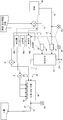
도 1은 제1 실시형태에 따른 배기가스 처리 장치의 개략 구성도이다.
도 2는 제1 실시형태의 배수 처리 탱크의 pH를 연속 측정한 결과를 도시한 그래프이다.
도 3은 제1 실시형태의 배수 처리 방법의 흐름을 설명하기 위한 흐름도이다.
도 4는 제2 실시형태에 따른 배기가스 처리 장치의 개략 구성도이다.
도 5는 제2 실시형태의 배수 처리 방법의 흐름을 설명하기 위한 흐름도이다.
도 6은 제3 실시형태에 따른 배기가스 처리 장치의 개략 구성도이다.
도 7은 제4 실시형태에 따른 배기가스 처리 장치의 개략 구성도이다.1 is a schematic configuration diagram of an exhaust gas processing apparatus according to the first embodiment.
2 is a graph showing the results of continuous measurement of the pH of the wastewater treatment tank of the first embodiment.
3 is a flowchart for explaining the flow of the drainage processing method of the first embodiment.
4 is a schematic configuration diagram of an exhaust gas processing apparatus according to the second embodiment.
5 is a flowchart for explaining the flow of the drainage processing method of the second embodiment.
6 is a schematic configuration diagram of an exhaust gas processing apparatus according to the third embodiment.
7 is a schematic configuration diagram of an exhaust gas processing apparatus according to the fourth embodiment.
이하, 본 발명의 실시형태에 대해 첨부 도면을 참조하여 상세히 설명한다. 도 1은 제1 실시형태에 따른 배기가스 처리 장치의 개략 구성도이다. 한편, 본 실시형태에 따른 배기가스 처리 장치로서는, 선박에 사용되는 엔진으로부터 배출되는 배기가스를 정화하는 장치를 고려한다. 단, 이것에 한정되지 않고, 본 실시형태에 따른 배기가스 처리 장치는, 화력 발전 플랜트나 화학 공업 플랜트, 폐기물 소각 시설에서의 배기가스의 처리에 적용 가능하다.Hereinafter, embodiments of the present invention will be described in detail with reference to the accompanying drawings. 1 is a schematic configuration diagram of an exhaust gas processing apparatus according to the first embodiment. On the other hand, as an exhaust gas treatment apparatus according to the present embodiment, an apparatus for purifying exhaust gas discharged from an engine used in a ship is considered. However, the present invention is not limited to this, and the exhaust gas treatment apparatus according to the present embodiment is applicable to treatment of exhaust gas in thermal power generation plants, chemical industrial plants, and waste incineration facilities.
여기서, 본 명세서 및 특허청구의 범위에서, 「알칼리 이온」이란, OH- 이온(수산화물 이온), HCO3 - 이온(탄산수소 이온), CO3 2- 이온(탄산 이온)을 의미하는 것이다.Herein, in the present specification and claims, "alkali ion" means OH - ion (hydroxide ion), HCO 3 - ion (hydrogen carbonate ion), CO 3 2- ion (carbonate ion).
도 1에 도시된 바와 같이, 배기가스 처리 장치는, 엔진(20)으로부터의 배기가스(g1)가 공급되는 스크러버(10)와, 스크러버(10)에 세정 해수(a1)를 공급하는 제1 해수 펌프(30)와, 스크러버(10)로부터의 배수(a2)가 도입되는 배수 처리 탱크(40)와, 배수 처리 탱크(40) 내에 희석 해수(a3)(알칼리성 물질)를 공급하는 제2 해수 펌프(공급 수단)(50)를 포함하여 구성된다. 한편, 본 실시형태의 배기가스 처리 장치를 각종 플랜트 등에 적용하는 경우에는, 엔진(20)을 대신하여 보일러를 이용해도 좋다.1, the exhaust gas treatment apparatus includes a
엔진(20)으로부터 배출된 배기가스(g1)는, 배기가스관(21)을 통해 스크러버(10)에 도입된다. 이 배기가스(g1)에는 SO2(이산화유황)가 포함된다. 또한, 스크러버(10) 내에는, 제1 해수 펌프(30)의 구동에 의해, 세정 해수관(31)을 통해 세정 해수(a1)가 도입된다. 스크러버(10) 내에 도입된 세정 해수(a1)는, 복수의 노즐(도시하지 않음)에 의해 분무되어, 스크러버(10) 내를 상승하는 배기가스(g1)와 기액(氣液) 접촉한다.The exhaust gas g1 discharged from the
배기가스(g1) 내의 SO2는, 하기 식 (1)에 나타낸 바와 같이, 세정 해수(a1)에 흡수되어, 수소 이온(H+)과 아황산 이온(HSO3 -)으로 해리된다. 또한, 수소 이온의 일부는, 하기 식 (2)에 나타낸 바와 같이, 세정 해수(a1) 중의 탄산수소 이온(HCO3 -)과 반응한다.SO 2 in the
SO2(gas)+H2O→H2SO3→H++HSO3 - …(1)SO 2 (gas) + H 2 O → H 2 SO 3 → H + + HSO 3 - ... (One)
H++HCO3 -→H2O+CO2(aq) …(2)H + + HCO 3 - → H 2 O + CO 2 (aq) ... (2)
스크러버(10)에 있어서, 배기가스(g1) 중의 SO2는, 세정 해수(a1)에 의해 흡수되어 제거된다. 따라서, 배기가스(g1)는, 스크러버(10) 내에서 정화된 정화 가스(g2)가 되어, 스크러버(10)의 상부로부터 대기 중으로 배기된다. 또한, 스크러버(10) 내에서, SO2를 흡수한 세정 해수(a1)는 배수(a2)가 되고, 배수(a2) 중에는 아황산 이온(HSO3 -)과 탄산(CO2)이 용해된 상태가 된다. 따라서, 배수(a2)의 pH(수소 이온 지수)는 3~5 정도가 된다. 스크러버(10) 내의 배수(a2)는, 스크러버(10)의 내벽면을 따라 자중(自重)으로 낙하하여, 스크러버(10) 하방의 저류부에 저류되고 나서 배수관(11)을 통해 배수 처리 탱크(40)에 배출된다.In the
배수 처리 탱크(40)에 도입된 배수(a2)는, 바다로 방류하기 위해서 산을 중화할 필요가 있다. 그 때문에, 배수 처리 탱크(40)에서는, 제2 해수 펌프(50)에 의해 희석 해수(a3)가 공급되고, 이 희석 해수(a3)가 스크러버(10)로부터의 배수(a2)와 혼합되어 배수(a2)가 희석된다. 또한, 배수 처리 탱크(40)에서는, 희석된 배수(a2)에 대해, 에어 공급 장치로서의 블로워(41)를 통해 공기를 혼입하는 폭기(에어레이션) 처리가 행해진다. 폭기 처리로서는, 블로워(41)로부터 공급되는 공기를, 배수 처리 탱크(40) 내의 노즐(42)로부터 미세한 버블 에어로서 분출하여, 배수 처리 탱크(40) 내의 희석된 배수(a2)에 접촉시키는 것을 예시할 수 있다. 배수 처리 탱크(40)에서의 폭기 처리에 있어서의 반응식은, 하기 식 (3)~(5)에 나타낸 바와 같이 된다.The drainage a2 introduced into the
HSO3 -+(1/2)O2→H++SO4 2- …(3)HSO 3 - + (1/2) O 2 - > H + + SO 4 2- ... (3)
H++HCO3 -→H2O+CO2(aq) …(4)H + + HCO 3 - → H 2 O + CO 2 (aq) ... (4)
CO2(aq)→CO2(gas)↑ …(5)CO 2 (aq) → CO 2 (gas) ↑ ... (5)
상기 반응에 의해, 배수 처리 탱크(40)에서 혼합된 희석 해수(a3) 및 배수(a2)에 있어서는, 아황산 이온(HSO3 -)이 산화함으로써, 황산 이온(SO4 2-)이 남아 중성이 되고, 수질 개선된 처리수(a4)가 되어 바다로의 방류가 가능해진다. 한편, 배수 처리 탱크(40)로부터 방출되는 처리수(a4)의 배출 경로(43)에는, 처리수(a4) 중의 pH를 계측하는 계측기(44)가 설치되어 있다.In, the diluted water (a3) and drain (a2) mixing in a
계속해서, 본 실시형태의 배기가스 처리 장치에 있어서, 제2 해수 펌프(50)에 의한 희석 해수(a3)의 공급 유량을 제어하는 구성에 대해 설명한다. 이러한 제어를 행하기 위해서, 배기가스 처리 장치는, 제1~제4 측정부(61~64)와, 제어부(65)를 구비하고 있다.Next, a configuration for controlling the supply flow rate of the diluted seawater a3 by the
제1 측정부(61)는, 배기가스관(21)에 설치되어, 스크러버(10)에 도입되기 전의 배기가스(g1)의 유량을 측정하는 매스 플로우 미터에 의해 구성된다. 제2 측정부(62)는, 배기가스관(21)에 설치되어, 스크러버(10)에 도입되기 전의 배기가스(g1)의 SO2 농도를 측정하는 레이저식 가스 분석계에 의해 구성된다. 제3 측정부(63)는, 스크러버(10)에 있어서의 정화 가스(g2)의 출구측에 설치되어, 스크러버(10)를 통과한 정화 가스(g2)의 SO2 농도를 측정하는 레이저식 가스 분석계에 의해 구성된다. 제4 측정부(64)는, 세정 해수관(31)에 설치되어, 스크러버(10)에 도입되는 세정 해수(a1)의 유량을 측정하는 매스 플로우 미터에 의해 구성된다. 각 측정부(61~64)는 측정 대상의 변동을 연속해서 측정 가능하게 구성된다. 한편, 상기 각 측정부(61~64)의 구성은 일례를 나타낸 것이며, 측정 대상의 변동을 측정 가능한 것을 전제로 하여, 임의의 구성을 채용할 수 있다.The
제어부(65)는, 예컨대 희석 해수(a3)의 공급의 제어에 필요한 각종 처리를 실행하는 프로세서나, ROM(Read Only Memory), RAM(Random Access Memory) 등의 기억 매체를 포함하는 프로그래머블 컨트롤러(PLC)에 의해 구성된다. 제어부(65)는, 각 측정부(61~64)와, 제2 해수 펌프(50)에 소정의 신호선을 통해 접속되어 있다. 각 측정부(61~64)의 측정 결과는, 전기 신호로서 제어부(65)에 출력된다. 제어부(65)는, 각 측정부(61~64)로부터 출력된 계측 결과에 기초하여 제2 해수 펌프(50)에 의한 희석 해수(a3)의 최적의 공급 유량을 연산한다. 그리고, 제어부(65)는, 상기 연산의 결과에 따른 전기 신호를 제2 해수 펌프(50)에 출력하여, 제2 해수 펌프(50)의 구동을 제어한다. 한편, 제어부(65)에 의해, 제2 해수 펌프(50)는 바람직하게는 인버터 제어된다.The
제2 해수 펌프(50)에 의한 희석 해수(a3)의 공급 유량은, 예컨대 이하에 서술한 바와 같이 연산한다. 여기서, 하기의 연산식에 있어서, 「C1」은, 제2 측정부(62)에 의해 측정되는 스크러버(10)에 도입되기 전의 배기가스(g1)의 SO2 농도를 나타내고, 「C2」는, 제3 측정부(63)에 의해 측정되는 스크러버(10)를 통과한 정화 가스(g2)의 SO2 농도를 나타내며, 그 측정 단위는 모두 ppm이다. 또한, 「G」는, 제1 측정부(61)에 의해 측정되는 스크러버(10)에 도입되기 전의 배기가스(g1)의 유량을 나타내고, 그 측정 단위는 N㎥(노멀 입방 미터)/h이다. 「W」는, 제4 측정부(64)에 의해 측정되는 스크러버(10)에 도입되는 세정 해수(a1)의 유량을 나타내고, 그 측정 단위는 ㎥/h이다.The supply flow rate of the diluted seawater a3 by the
먼저, 세정 해수(a1)에 흡수되어 HSO3 - 이온이 된 양 「S1」(단위: ㏖/h)을 하기 식 (6)에 의해 연산한다. 한편, 1몰의 기체의 체적은 22.4리터이다.First, is absorbed in the washing water (a1) HSO 3 - ions is the amount "S1" (unit: ㏖ / h) is calculated by the following equation (6). On the other hand, the volume of one mole of gas is 22.4 liters.
S1=(C1-C2)÷22.4×G×10-3 …(6)S1 = (C1-C2) / 22.4 x G x 10 -3 ... (6)
계속해서, 희석 해수(a3)의 유량을 Q1(㎥/h)로 하고, 공급되는 해수 전체, 즉 세정 해수(a1)와 희석 해수(a3)의 총합에 있어서의 HCO3 - 이온(알칼리 이온)의 양 「S2」(단위: ㏖/h)를 하기 식 (7)에 의해 연산한다. 여기서, 하기 식 (7)에서는, 해수의 알칼리 이온 농도를 2.0×10⁻³ ㏖/L로 하였으나, 날씨나 해역에 따라 농도가 변화하는 것이 고려되기 때문에, 정기적으로 해수의 알칼리 이온 농도를 분석하여, 식 (7)에 반영하는 것이 바람직하다. 예컨대, 현재 위치를 측정하고, 이 현재 위치에 기초한 운행 해역 정보를 출력하는 GPS를 더 구비해도 좋다. 제어부(65)는, GPS로부터 출력된 운행 해역 정보에 기초하여, 해수의 알칼리 이온 농도를 갱신해도 좋다. 운행 해역에 대응하는 해수의 알칼리 이온 농도는, 미리 제어부(65)에 기억되어 있어도 좋고, 알칼리도 측정기를 이용하여 측정해도 좋다.HCO 3 in the total of the continuously diluted sea water (a3) a flow rate of Q1 (㎥ / h) total to and supplied water, i.e. the cleaning water (a1) of the dilution water (a3) - ion (Alkaline) Quot; S2 " (unit: mol / h) is calculated by the following equation (7). Here, in the following equation (7), although the alkali ion concentration of the seawater is 2.0 × 10 -3 mol / L, it is considered that the concentration changes depending on the weather and the sea area. Therefore, the alkali ion concentration of the seawater is analyzed periodically , And (7). For example, it may further comprise a GPS for measuring the current position and outputting the operating area information based on the current position. The
S2 = (희석 해수의 HCO3 - 이온량)+(세정 해수의 HCO3 - 이온량)S2 = (HCO 3 - ion amount of diluted seawater) + (HCO 3 - ion amount of washed seawater)
= (2.0×10⁻³×Q1×103)+(2.0×10⁻³×W×103)= (2.0 x 10 -3 x Q 1 x 10 3 ) + (2.0 x 10 -3 x W x 10 3 )
= 2Q1+2W …(7) = 2Q1 + 2W ... (7)
다음으로, 식 (6), (7)의 연산 결과를 이용하여, 적절한 희석 해수(a3)의 유량(Q1)을, 하기 식 (8)에 의해 연산한다. 이 연산에서는, 배수 처리 탱크(40) 중의 배수(a2)를 수질 개선한 처리수(a4)로 하는 것이 요구된다. 그래서, 세정 해수(a1)와 희석 해수(a3)의 HCO3 - 이온(알칼리 이온)의 총량 「S2」가, 세정 해수(a1)에 흡수되어 HSO3 -가 된 양 「S1」에 계수 「A」가 곱해진 값에 비해, 크게 되는 부등식을 이용한다.Next, the flow rate Q1 of the diluted aqueous solution a3 is calculated by the following equation (8) using the calculation results of the equations (6) and (7). In this calculation, it is required that the drainage a2 in the
(세정 해수와 희석 해수의 HCO3 - 이온의 양의 총합) > A×(세정 해수에 흡수되어 HSO3 - 이온이 된 양)(Total amount of HCO 3 - ion in washed sea water and diluted seawater)> A × (amount of HSO 3 - ion absorbed in washing seawater)
S2 > A×S1S2 > A x S1
2Q1+2W > A×{(C1-C2)÷22.4×G×10-3}2Q1 + 2W > A x {(C1-C2) / 22.4 x G x 10 -3 }
Q1 > [A×{(C1-C2)÷22.4×G×10-3}-2W]÷2 …(8)Q1 > [A x {(C1-C2) / 22.4 x G x 10 -3 } -2W] / 2 ... (8)
이상과 같이, 배수 처리 탱크(40)에 공급되는 희석 해수(a3)의 유량(Q1)은, 식 (8)의 우변의 연산 결과보다 많아진다. 한편, 실제 운전 시에는, 연산한 식 (8)의 우변의 연산 결과에 비해 유량(Q1)이 확실하게 커지도록, 식 (8)의 우변의 연산 결과에 대해 약 1.05배~1.15배의 유량(Q1)을 설정값으로서 이용해도 좋다. 상기 식 (6)~식 (8)의 연산은, 제어부(65)에 의해, 수분(예컨대 5분) 간격으로 실시하여, 희석 해수(a3)의 유량(Q1)을 갱신하도록 제어를 행한다.As described above, the flow rate Q1 of the diluted seawater a3 supplied to the
여기서, 도 2를 참조하여, 식 (8)에서의 계수(A)의 설정 방법에 대해 설명한다. 도 2는 해수량을 변화시켰을 때의 배수 처리 탱크의 pH를 연속 측정한 결과를 도시한 그래프이다. 도 2에서는, 하기 식 (9)에서 연산되는 계수(A)를 0, 0.5, 1, 2, 2.33, 4, 8로 변화시켰을 때의 pH의 결과이다.Here, a method of setting the coefficient A in the equation (8) will be described with reference to FIG. 2 is a graph showing the results of continuous measurement of the pH of the wastewater treatment tank when the amount of seawater is changed. 2 shows the result of pH when the coefficient A calculated in the following equation (9) is changed to 0, 0.5, 1, 2, 2.33, 4,
A = (해수로부터 공급되는 HCO3 - 이온(알칼리 이온)의 양)A = (amount of HCO 3 - ion (alkali ion) supplied from seawater)
÷ (세정 해수에 흡수되어 HSO3 - 이온이 된 양) …(9)÷ (Amount of HSO 3 - ion absorbed in washing sea water) ... (9)
도 2의 결과로부터, 배수 처리 탱크(40)에서 처리된 처리수(a4)는, A≥2의 조건에 있어서, pH가 6.5~8.6이 되는 것을 알 수 있고, 동(同) 조건으로 처리수(a4)를 바다로 방류할 수 있다. 한편, A=4, 8의 조건이어도 처리수(a4)를 바다로 방류할 수 있는 pH가 되지만, 과잉으로 희석 해수(a3)를 공급하게 된다. 본 실시형태에서는, 2≤A≤2.33의 범위에 있어서, pH를 7 정도로 할 수 있다. 즉, 2≤A≤2.33의 범위이면, 처리수(a4)를 바다로 방류 가능한 수질로 하면서, 예컨대 세정 해수(a1)의 양에 대해 희석 해수(a3)의 양을 2배 이하로 해서 과잉이 되는 것을 억제하여, 제2 해수 펌프(50)의 에너지 절약화를 도모할 수 있다.It can be seen from the results in Fig. 2 that the treated water a4 treated in the
다음으로, 도 1로 되돌아가서, 상기 제어부(65)의 구성에 대해 설명한다. 도 1에서는 제어부(65)를 기능 블록도로서 나타낸다. 한편, 도 1에 도시된 제어부(65)의 기능 블록은, 본 발명에 관련된 구성만을 나타내고 있으며, 그 이외의 구성에 대해서는 생략하고 있다.Next, returning to Fig. 1, the configuration of the
도 1에 도시된 바와 같이, 제어부(65)는 입력부(65a), 연산부(65b) 및 출력부(65c)를 포함하여 구성되어 있다. 입력부(65a)는, 제1~제4 측정부(61~64)의 유량이나 농도의 측정값을 전기 신호로서 입력한다. 연산부(65b)는, 입력부(65a)에 입력된 각 측정값으로부터, 상기 식 (6)으로 나타낸 세정 해수(a1)에 흡수되어 HSO3 -가 된 양 「S1」, 식 (7)로 나타낸 세정 해수(a1)와 희석 해수(a3)의 HCO3 - 이온의 양의 총합 「S2」를 연산한다. 그리고, 이 양 「S1」, 「S2」의 연산 결과에 따라, 상기 식 (8)로 나타낸 적절한 희석 해수(a3)의 유량 「Q1」을 연산한다. 출력부(65c)는, 연산부(65b)의 유량 「Q1」의 연산 결과에 따라, 제2 해수 펌프(50)의 구동을 제어하기 위한 전기 신호를 출력한다. 또한, 출력부(65c)는, 블로워(41)를 통해 배수 처리 탱크(40) 내의 노즐(42)로부터 미세한 버블 에어를 분출하기 위한 전기 신호를 출력한다.As shown in Fig. 1, the
계속해서, 도 1 및 도 3을 참조하여, 상기 배기가스 처리 장치에서의 배수 처리 방법에 대해 설명한다. 도 3은 배수 처리 방법의 흐름을 설명하기 위한 흐름도이다. 도 3에 도시된 바와 같이, 본 실시형태의 배수 처리 방법에서는, 정화 공정(ST1), 측정 공정(ST2), 연산 공정(ST3) 및 공급 공정(ST4)이 행해진다.Next, with reference to Fig. 1 and Fig. 3, the waste water treatment method in the above-described exhaust gas treatment apparatus will be described. 3 is a flow chart for explaining the flow of the waste water treatment method. As shown in Fig. 3, in the wastewater treatment method of the present embodiment, the purification step (ST1), the measurement step (ST2), the calculation step (ST3), and the supply step (ST4) are performed.
먼저, 정화 공정(ST1)에서는, 엔진(20)으로부터의 배기가스(g1)가 배기가스관(21)을 통해 스크러버(10) 내에 도입된다. 한편, 제1 해수 펌프(30)의 구동에 의해 스크러버(10) 내에서는, 세정 해수관(31)을 통해 세정 해수(a1)가 안개 형상으로 분사된다. 이에 의해, 배기가스(g1) 중에 포함되는 SO2와 안개 형상의 세정 해수(a1)가 접촉하여 세정 해수(a1)에 SO2가 흡수되고, 배기가스(g1)가 정화되어 정화 가스(g2)로서 스크러버(10)로부터 배출된다. SO2를 흡수한 세정 해수(a1)는, 배수(a2)로서 스크러버(10)로부터 배수 처리 탱크(40) 내에 도입된다.First, in the purifying step ST1, the exhaust gas g1 from the
상기 정화 공정을 행하면서, 측정 공정(ST2)이 행해진다. 측정 공정에서는, 제1 측정부(61)에 의해, 배기가스관(21)을 흘러 스크러버(10)에 도입되기 전의 배기가스(g1)의 유량이 측정되고, 제2 측정부(62)에 의해 상기 배기가스(g1)의 SO2 농도가 측정된다. 또한, 제3 측정부(63)에 의해, 스크러버(10)의 출구측을 통과한 정화 가스(g2)의 SO2 농도가 측정되고, 제4 측정부(64)에 의해, 세정 해수관(31)을 흘러 스크러버(10)에 도입되는 세정 해수(a1)의 유량이 측정된다.The measurement step (ST2) is performed while performing the above purification process. The flow rate of the exhaust gas g1 before the
상기 측정 공정에서의 측정값에 기초하여 연산 공정(ST3)이 행해진다. 연산 공정에서는, 먼저 전술한 바와 같이, 제어부(65)에 의해 세정 해수(a1)에 흡수되어 HSO3 -가 된 양이 연산되고, 이 연산 결과에 따라 적절한 희석 해수(a3)의 유량이 연산된다.And the calculating step (ST3) is performed based on the measured value in the measuring step. In the calculation process, as described above, the amount of the HSO 3 - absorbed in the cleansing water a1 by the
정화 공정(ST1) 및 연산 공정(ST3)이 행해지면, 공급 공정(ST4)이 행해진다. 공급 공정에서는, 연산 공정의 연산 결과에 따라, 제어부(65)에 의해 제2 해수 펌프(50)의 구동을 제어하여 희석 해수(a3)가 배수 처리 탱크(40)에 공급된다. 그리고, 배수 처리 탱크(40) 내에서, 스크러버(10)로부터의 배수(a2)가, 제2 해수 펌프(50)에 의해 공급된 희석 해수(a3)와 혼합되어 희석된다. 그 후, 배수 처리 탱크(40)에서는, 희석된 배수(a2)에 대해 폭기 처리가 행해지고, 배수(a2)를 수질 개선한 처리수(a4)로서 해수 중으로 방류된다. 처리수(a4)는, 바다로 방류되기 전에 계측기(44)에 의해 pH가 측정된다. 한편, 배수(a2)와 희석 해수(a3)의 혼합 및 폭기 처리를 동시에 행해도 좋다. 동시에 행한 경우라도, 배수(a2)는 수질 개선된 처리수(a4)로서 해수 중으로 방류된다.When the purifying step ST1 and the calculating step ST3 are performed, the supplying step ST4 is performed. In the supplying step, the
이상 설명한 바와 같이, 본 실시형태에 따른 배수 처리 방법에 의하면, 제1~제4 측정부(61~64)의 측정값에 따라, 배수(a2)를 희석하는 희석 해수(a3)를 적절한 양으로 조정하기 때문에, 처리수(a4)의 수질을 바다로 방류할 수 있는 pH가 되도록 충분히 개선하면서, 희석 해수(a3)의 양을 삭감할 수 있다. 이에 의해, 제2 해수 펌프(50)를 구동하기 위한 소비 전력에 낭비가 생기는 것을 억제할 수 있다. 게다가, 희석된 배수(a2)의 양을 삭감할 수 있기 때문에, 폭기 처리에서의 블로워(41)를 구동하기 위한 소비 전력도 억제할 수 있고, 폭기 처리의 단시간화를 도모할 수 있다.As described above, according to the wastewater treatment method of the present embodiment, the diluted seawater a3 for diluting the drainage water a2 is adjusted to an appropriate amount according to the measured values of the first to
한편, 상기에 있어서, 세정 해수(a1)의 유량은, 미리 정해진 설정값을 이용할 수도 있고, 별도로 결정된 값을 이용할 수도 있다. 또한, 다음으로 설명하는 본 발명의 제2 실시형태와 같이, 제어부(65)에 의해 값을 결정할 수도 있다. 미리 정해진 설정값을 이용하는 경우에는, 제4 측정부(64)에 의한 세정 해수(a1)의 유량의 측정은 필요 없기 때문에, 제4 측정부(64)가 불필요해질 수 있다.On the other hand, in the above, the flow rate of the washing seawater a1 may be a predetermined set value or a value determined separately. In addition, the value may be determined by the
다음으로, 본 발명의 제2 실시형태에 대해 도 4를 참조하여 상세히 후술한다. 한편, 제2 실시형태에 있어서, 제1 실시형태와 공통되는 구성요소에 대해서는 동일한 부호를 붙이고, 그 도시, 설명을 생략한다.Next, a second embodiment of the present invention will be described in detail below with reference to Fig. On the other hand, in the second embodiment, constituent elements common to those in the first embodiment are denoted by the same reference numerals, and a description thereof is omitted.
도 4는 제2 실시형태에 따른 배기가스 처리 장치의 개략 구성도이다. 도 4에 도시된 바와 같이, 본 실시형태에 따른 배기가스 처리 장치에서는, 제어부(65)가 세정 해수(a1)의 유량을 결정한다. 제어부(65)는, 제2 측정부(62)에 의해 측정된 스크러버(10)에 도입되기 전의 배기가스(g1)의 SO2 농도와, 제3 측정부(63)에 의해 측정된 스크러버(10)의 출구측을 통과한 정화 가스(g2)의 SO2 농도를 이용하여 탈황율(SO2 농도의 제거율)을 연산한다. 탈황율이 소정의 임계값을 하회한 경우에는, 제어부(65)는, 세정 해수(a1)의 유량이 증가하도록, 제1 해수 펌프(30)의 구동을 제어한다. 탈황율은, 예컨대 제2 측정부(62)에 의해 측정된 스크러버(10)에 도입되기 전의 배기가스(g1)의 SO2 농도와, 제3 측정부(63)에 의해 측정된 스크러버(10)의 출구측을 통과한 정화 가스(g2)의 SO2 농도의 비[정화 가스(g2)의 SO2 농도/배기가스(g1)의 SO2 농도]에 의해 연산된다.4 is a schematic configuration diagram of an exhaust gas processing apparatus according to the second embodiment. As shown in Fig. 4, in the exhaust gas treatment apparatus according to the present embodiment, the
또한, 제어부(65)는, 제1 실시형태와 마찬가지로, 세정 해수(a1)의 HCO3 - 이온량과 희석 해수의 HCO3 - 이온량의 총합이, 세정 해수(a1)에 흡수되어 HSO3 - 이온이 된 몰수에 대해 2배 이상 2.33배 이하가 되도록, 제2 해수 펌프(50)의 구동을 제어한다. 이에 의해, 세정 해수(a1) 및 희석 해수(a3)를 낭비 없이 효율적으로 사용할 수 있다. 예컨대, 탈황율을 올리기 위해서 세정 해수(a1)의 유량을 증가시킨 경우에는, 그 증가분에 상당하는 유량의 희석 해수(a3)를 삭감할 수 있다.In addition, the
또한, 제어부(65)는, 세정 해수(a1)의 HCO3 - 이온량이, 세정 해수(a1)에 흡수되어 HSO3 - 이온이 된 몰수에 대해 2배 이상 2.33배 이하가 되도록, 제1 해수 펌프(30)를 제어할 수도 있다. 이 경우에는, 희석 해수(a3)가 불필요하게 되기 때문에, 제2 해수 펌프(50)의 동력을 삭감할 수 있다.The
계속해서, 도 4 및 도 5를 참조하여, 본 발명의 제2 실시형태의 배기가스 처리 장치에서의 배수 처리 방법에 대해 설명한다. 도 5는 배수 처리 방법의 흐름을 설명하기 위한 흐름도이다. 도 5에 도시된 바와 같이, 본 실시형태의 배수 처리 방법에서는, 정화 공정(ST11), 측정 공정(ST12), 제1 연산 공정(ST13), 제1 공급 공정(ST14), 제2 연산 공정(ST15) 및 제2 공급 공정(ST16)이 행해진다.Next, with reference to Fig. 4 and Fig. 5, a waste water treatment method in the waste gas treatment apparatus according to the second embodiment of the present invention will be described. 5 is a flowchart for explaining the flow of the drainage processing method. 5, in the wastewater treatment method of the present embodiment, the purification step ST11, the measurement step ST12, the first calculation step ST13, the first supply step ST14, the second calculation step ST15) and the second supply step (ST16) are performed.
먼저, 정화 공정(ST11)에서는, 엔진(20)으로부터의 배기가스(g1)가 배기가스관(21)을 통해 스크러버(10) 내에 도입된다. 한편, 제어부(65)의 입력부(65a)에는, 엔진(20)의 출력값이 입력된다. 연산부(65b)에서는, 엔진(20)의 출력값에 기초하여 연료 소비량이 연산된다. 또한, 연산부(65b)에서는, 연료 소비량에 기초하여, 배기가스(g1)의 정화에 필요한 세정 해수(a1)의 유량이 연산된다. 출력부(65c)는, 이 연산 결과에 기초하여, 필요한 유량의 세정 해수(a1)를 스크러버(10)에 도입하도록, 제1 해수 펌프(30)를 구동시킨다. 제1 해수 펌프(30)의 구동에 의해, 세정 해수(a1)가 세정 해수관(31)을 지나, 스크러버(10) 내에서 안개 형상으로 배기가스(g1)에 대해 분사된다. 이에 의해, 배기가스(g1) 중에 포함되는 SO2와 안개 형상의 세정 해수(a1)가 접촉하여 세정 해수(a1)에 SO2가 흡수되고, 배기가스(g1)가 정화되어 정화 가스(g2)로서 스크러버(10)로부터 배출된다. SO2를 흡수한 세정 해수(a1)는, 배수(a2)로서 스크러버(10)로부터 배수 처리 탱크(40) 내에 도입된다.First, in the purifying step ST11, the exhaust gas g1 from the
상기 정화 공정을 행하면서, 측정 공정(ST12)이 행해진다. 측정 공정에서는, 제1 측정부(61)에 의해, 배기가스관(21)을 흘러 스크러버(10)에 도입되기 전의 배기가스(g1)의 유량이 측정되고, 제2 측정부(62)에 의해 상기 배기가스(g1)의 SO2 농도가 측정된다. 또한, 제3 측정부(63)에 의해, 스크러버(10)의 출구측을 통과한 정화 가스(g2)의 SO2 농도가 측정되고, 제4 측정부(64)에 의해, 세정 해수관(31)을 흘러 스크러버(10)에 도입되는 세정 해수(a1)의 유량이 측정된다.The measurement step (ST12) is performed while performing the above purification process. The flow rate of the exhaust gas g1 before the
상기 측정 공정에서의 측정값에 기초하여, 제1 연산 공정(ST13)이 행해진다. 제1 연산 공정에서는, 먼저, 전술한 바와 같이, 제어부(65)는, 제2 측정부(62)에 의해 측정된 스크러버(10)에 도입되기 전의 배기가스(g1)의 SO2 농도와, 제3 측정부(63)에 의해 측정된 스크러버(10)의 출구측을 통과한 정화 가스(g2)의 SO2 농도를 이용하여 탈황율을 연산한다. 그리고, 이 탈황율에 따라, 제어부(65)에 의해 제1 해수 펌프(30)의 구동을 제어하여 세정 해수(a1)가 스크러버(10)에 공급된다.The first calculation step (ST13) is performed based on the measurement value in the measurement step. In the first operation step, first, the
제1 연산 공정(ST13)이 행해지면, 제1 공급 공정(ST14)이 행해진다. 제1 공급 공정에 있어서, 제어부(65)는, 연산한 탈황율을 미리 정해진 임계값과 비교한다. 탈황율이 임계값을 하회한 경우에는, 제어부(65)는, 세정 해수(a1)의 유량이 증가하도록, 제1 해수 펌프(30)의 구동을 제어한다.When the first calculation step (ST13) is performed, the first supply step (ST14) is performed. In the first supply step, the
제1 공급 공정(ST14)이 행해지면, 상기 측정 공정에서의 측정값에 기초하여, 제2 연산 공정(ST15)이 행해진다. 제2 연산 공정에서는, 전술한 바와 같이, 제어부(65)에 의해 세정 해수(a1)에 흡수되어 HSO3 -가 된 양이 연산되고, 이 연산 결과에 따라 적절한 희석 해수(a3)의 유량이 연산된다.When the first supplying step (ST14) is performed, the second calculating step (ST15) is performed based on the measured value in the measuring step. In the second calculation step, as described above, the amount of the HSO 3 - absorbed by the cleaned seawater a 1 by the
정화 공정(ST11) 및 제2 연산 공정(ST15)이 행해지면, 제2 공급 공정(ST16)이 행해진다. 제2 공급 공정에서는, 제2 연산 공정의 연산 결과에 따라, 제어부(65)에 의해 제2 해수 펌프(50)의 구동을 제어하여 희석 해수(a3)가 배수 처리 탱크(40)에 공급된다. 그리고, 배수 처리 탱크(40) 내에서, 스크러버(10)로부터의 배수(a2)가, 제2 해수 펌프(50)에 의해 공급된 희석 해수(a3)와 혼합되어 희석된다. 그 후, 배수 처리 탱크(40)에서는, 희석된 배수(a2)에 대해, 폭기 처리가 행해지고, 배수(a2)를 수질 개선한 처리수(a4)로서 해수 중으로 방류된다. 처리수(a4)는, 바다로 방류되기 전에, 계측기(44)에 의해 pH가 측정된다. 한편, 배수(a2)와 희석 해수(a3)의 혼합 및 폭기 처리를 동시에 행해도 좋다. 동시에 행한 경우라도, 배수(a2)는 수질 개선된 처리수(a4)로서 해수 중으로 방류된다.When the purifying step ST11 and the second calculating step ST15 are performed, the second supplying step ST16 is performed. In the second supply step, the
다음으로, 이하, 본 발명의 제3 실시형태에 대해 도 6을 참조하여 상세히 설명한다. 한편, 제3 실시형태에 있어서, 제1 및 제2 실시형태와 공통되는 구성요소에 대해서는, 동일한 부호를 붙이고, 그 도시, 설명을 생략한다.Next, a third embodiment of the present invention will be described in detail with reference to Fig. On the other hand, in the third embodiment, constituent elements common to those of the first and second embodiments are denoted by the same reference numerals, and the illustration and description thereof are omitted.
도 6은 제3 실시형태에 따른 배기가스 처리 장치의 개략 구성도이다. 도 6에 도시된 바와 같이, 본 실시형태에 따른 배기가스 처리 장치에서는, 알칼리성 물질(a5)을 저장하는 저장 탱크(80)를 구비하고 있다. 저장 탱크(80) 내의 알칼리성 물질(a5)은, 공급 수단으로서의 펌프(90)를 통해 배수 처리 탱크(40)에 공급되어 배수(a2)와 혼합된다. 즉, 제3 실시형태에서는, 제1 실시형태의 희석 해수(a3)를 대신하여 저장 탱크(80) 내의 알칼리성 물질(a5)을 이용하고 있다. 펌프(90)는, 제어부(65)에 의해, 제1 실시형태의 제2 해수 펌프(50)와 동일하게 제어된다.6 is a schematic configuration diagram of an exhaust gas processing apparatus according to the third embodiment. As shown in Fig. 6, the exhaust gas processing apparatus according to the present embodiment is provided with a
알칼리성 물질(a5)로서는, 정해진 농도로 희석된 NaOH 수용액, Mg(OH)2 슬러리액, Ca(OH)2 슬러리액, 및 CaCO3 슬러리액을 예시할 수 있고, 이들을 단일로 이용하는 것 외에, 복수의 조합으로 혼합시킨 것을 이용해도 좋다.Examples of the alkaline substance (a5) include NaOH aqueous solution, Mg (OH) 2 slurry, Ca (OH) 2 slurry, and CaCO 3 slurry diluted to a predetermined concentration. May be used.
펌프(90)에 의한 알칼리성 물질(a5)의 공급 유량을 Q2(㎥/h)로 한 경우, 그 연산은, 제1 실시형태에서의 희석 해수(a3)의 유량(Q1)의 연산에 대해, 이하에 서술하는 점이 변경된다. 제3 실시형태에서는, 「S2」(단위: ㏖/h)를, 세정 해수(a1)와 알칼리성 물질(a5)의 총합에 있어서의 알칼리 이온의 양으로 하여, 하기 식 (7a)에 의해 연산한다. 여기서, 하기 식 (7a)에 있어서, 「M」은 알칼리성 물질(a5)의 알칼리 이온 농도(단위: ㏖/L)이다.When the supply flow rate of the alkaline substance a5 by the
S2 = (알칼리성 물질의 알칼리 이온량)+(세정 해수의 알칼리 이온량)S2 = (amount of alkaline ion of alkaline substance) + (amount of alkaline ion of washing sea water)
= (M×Q2×103)+(2.0×10⁻³×W×103)= (M x Q 2 x 10 3 ) + (2.0 x 10 -3 x W x 10 3 )
= M×Q2×103+2W …(7a)= M x Q 2 x 10 3 + 2W ... (7a)
식 (6), (7a)의 연산 결과를 이용하여, 적절한 알칼리성 물질(a5)의 유량(Q2)을, 하기 식 (8a)에 의해 연산한다.The flow rate Q2 of the appropriate alkaline substance a5 is calculated by the following equation (8a) using the calculation results of the equations (6) and (7a).
(세정 해수와 알칼리성 물질의 알칼리 이온의 양의 총합) > A×(세정 해수에 흡수되어 HSO3 - 이온이 된 양)(Total sum of the amount of alkaline ions of the washing water and the alkaline substance) > A x (the amount absorbed into the washing seawater to become the HSO 3 - ion)
S2 > A×S1S2 > A x S1
M×Q2×103+2W > A×{(C1-C2)÷22.4×G×10-3}M x Q 2 x 10 3 + 2W> A x {(C1-C2) / 22.4 x G x 10 -3 }
Q2 > [A×{(C1-C2)÷22.4×G×10-3}-2W]÷(M×103) …(8a)Q2> [A × {(C1-C2) / 22.4 × G × 10 -3 } -2W] / (M × 10 3 ) (8a)
이상과 같이, 배수 처리 탱크(40)에 공급되는 알칼리성 물질(a5)의 유량(Q2)은, 식 (8a)의 우변의 연산 결과보다 많아진다. 제3 실시형태에서도, 계수(A)를 2≤A≤2.33의 범위에서 설정함으로써, 처리수(a4)를 바다로 방류 가능한 수질로 하면서, 알칼리성 물질(a5)의 양이 과잉이 되는 것을 억제하여, 펌프(90)의 에너지 절약화를 도모할 수 있다. 한편, 실제 운전 시에는, 연산한 식 (8a)의 우변의 연산 결과에 비해 유량(Q2)이 확실하게 커지도록, 식 (8a)의 우변의 연산 결과에 대해 약 1.05~1.15배의 유량(Q2)을 설정값으로서 이용해도 좋다. 상기 식 (6), 식 (7a), 식 (8a)의 연산은, 제어부(65)에 의해, 예컨대 5분 간격으로 실시하여, 알칼리성 물질(a5)의 유량(Q2)을 갱신하도록 제어를 행한다. 또한, 여기서, 상기 식 (7a)에서는, 해수의 알칼리 이온 농도를 2.0×10⁻³ ㏖/L로 하였으나, 날씨나 해역에 따라 농도가 변화하는 것이 고려되기 때문에, 정기적으로 해수의 알칼리 이온 농도를 분석하여, 식 (7a)에 반영하는 것이 바람직하다. 예컨대, 현재 위치를 측정하고, 이 현재 위치에 기초한 운행 해역 정보를 출력하는 GPS를 더 구비해도 좋다. 제어부(65)는, GPS로부터 출력된 운행 해역 정보에 기초하여, 해수의 알칼리 이온 농도를 갱신해도 좋다. 운행 해역에 대응하는 해수의 알칼리 이온 농도는, 미리 제어부(65)에 기억되어 있어도 좋고, 알칼리도 측정기를 이용하여 측정해도 좋다.As described above, the flow rate Q2 of the alkaline substance a5 supplied to the
이상과 같이, 제3 실시형태에 의하면, 배수 처리 탱크(40) 내의 배수(a2)를 중화하여, 처리수(a4)로서 바다로 방류 가능한 수질로 하기 때문에, 알칼리 수용액이나 알칼리 슬러리액으로 이루어지는 알칼리성 물질(a5)을 적량 공급할 수 있어, 알칼리성 물질(a5)의 쓸데없는 소비를 삭감할 수 있다.As described above, according to the third embodiment, since the waste water a2 in the waste
또한, 이하, 본 발명의 제4 실시형태에 대해 도 7을 참조하여 상세히 설명한다. 한편, 제4 실시형태에 있어서, 제1, 제2 및 제3 실시형태와 공통되는 구성요소에 대해서는, 동일한 부호를 붙이고, 그 도시, 설명을 생략한다.Hereinafter, a fourth embodiment of the present invention will be described in detail with reference to Fig. On the other hand, in the fourth embodiment, constituent elements common to the first, second and third embodiments are denoted by the same reference numerals, and a description thereof will be omitted.
도 7은 제4 실시형태에 따른 배기가스 처리 장치의 개략 구성도이다. 도 7에 도시된 바와 같이, 본 실시형태에 따른 배기가스 처리 장치에서는, 처리수(a4)를 바다로 방류하지 않고 순환 사용할 수 있다. 또한, 본 실시형태에 따른 배기가스 처리 장치에서는, 제3 실시형태와 마찬가지로, 알칼리성 물질(a5)을 저장하는 저장 탱크(80)를 구비하고 있다. 저장 탱크(80) 내의 알칼리성 물질(a5)은, 공급 수단으로서의 펌프(90)를 통해 배수 처리 탱크(40)에 공급되어 배수(a2)와 혼합된다.7 is a schematic configuration diagram of an exhaust gas processing apparatus according to the fourth embodiment. As shown in Fig. 7, in the exhaust gas treatment apparatus according to the present embodiment, the treated water a4 can be circulated without being discharged to the sea. In the exhaust gas treatment apparatus according to the present embodiment, similarly to the third embodiment, a
제어부(65)는, 배수 처리 탱크(40) 내에서 수질 개선한 처리수(a4)를 배출 유로(43)로부터 분기되는 순환 해수관(71)에 의해 세정 해수관(31)으로 복귀시켜, 순환수(a6)로서 순환 사용한다(순환 공정). 순환수(a6)는, 세정 해수관(31)을 통해 세정 해수로서 스크러버(10)에 공급된다. 순환수(a6)의 유량은, 제4 측정부(64)에 의해, 스크러버(10)에 도입되기 전에 측정된다. 또한, 처리수(a4) 중의 pH는, 계측기(44)에 의해 계측되고 있다.The
제어부(65)는, 계측기(44)의 pH의 측정값에 기초하여, 분기되는 지점에 설치된 전환 밸브(h1 및 h2)의 개폐를 제어함으로써, 처리수(a4)를 바다로 방류하는 경우(방류 공정)와, 처리수(a4)를 선박 내에서 순환 사용하는 경우(순환 공정)를 전환할 수 있다(전환 공정).The
이상과 같이, 본 실시형태에 의하면, 처리수(a4)를 바다로 방류하지 않고 선박 내에서 순환 사용할 수 있다. 그 때문에, 규제 등에 의해 처리수(a4)를 바다로 방류할 수 없는 운행 해역에서도, 처리수(a4)를 순환 사용함으로써, 스크러버(10)에서 배기가스(g1)를 정화할 수 있다. 또한, 선박의 운행 해역의 pH 규제값에 따라, 처리수(a4)를 바다로 방류하는 경우와, 선박 내에서 순환 사용하는 경우를 전환할 수 있다. 한편, 본 실시형태에서는, 제3 실시형태에 대해, 순환 해수관(71) 등의 구성요소를 추가하였으나, 이러한 구성요소를 제1 또는 제2 실시형태에 대해 추가한 배기가스 처리 장치로 해도 좋다.As described above, according to the present embodiment, the treated water a4 can be circulated in the ship without being discharged to the sea. Therefore, the exhaust gas g1 can be purified by the
실시예Example
다음으로, 상기한 실시형태에 따른 배수 처리 방법에서의 수질 개선 및 에너지 절약 효과를 확인하기 위해서 행한 실험에 대해 설명한다. 본 실험의 실시예 1에서는, 제1 실시형태와 마찬가지로, 희석 해수를 사용하였다. 실시예 2~4에서는, 제2 실시형태와 마찬가지로, 알칼리성 물질을 사용하였다. 구체적으로는, 실시예 2에서 50% NaOH 수용액, 실시예 3에서 35% Mg(OH)2 슬러리액, 실시예 4에서 30% Ca(OH)2 슬러리액을 사용하였다. 실시예 1~4에 있어서, 하기의 표 1의 조건에 대해서는 공통된 조건으로 설정하였다. 실시예 2~4의 알칼리성 물질에 대한 알칼리 이온 농도(M)는, 실시예 2에서는 12.5 ㏖/L, 실시예 3에서는 12.0 ㏖/L, 실시예 4에서는 8.0 ㏖/L로 설정하였다.Next, an experiment conducted to confirm the water quality improvement and the energy saving effect in the wastewater treatment method according to the above embodiment will be described. In Example 1 of the present experiment, diluted seawater was used as in the first embodiment. In Examples 2 to 4, an alkaline substance was used as in the second embodiment. Specifically, 50% NaOH aqueous solution in Example 2, 35% Mg (OH) 2 slurry in Example 3, and 30% Ca (OH) 2 slurry in Example 4 were used. In Examples 1 to 4, the conditions shown in Table 1 below were set under common conditions. The alkaline ion concentration (M) for the alkaline substance of Examples 2 to 4 was set to 12.5 mol / L in Example 2, 12.0 mol / L in Example 3, and 8.0 mol / L in Example 4.
실시예 1의 각 조건을, 상기 식 (8)에 대입하여 연산하면, Q1 > 786 ㎥/h가 되었기 때문에, 확실하게 처리수(a4)를 바다로 방류할 수 있는 pH가 되도록, 희석 해수(a3)의 유량이 830 ㎥/h가 되도록 제2 해수 펌프(50)를 인버터 제어하였다. 이 연산은, 제어부(65)에 의해 5분 간격으로 실시하여, 희석 해수(a3)의 유량(Q1)을 갱신하도록 제어를 행하였다. 그 결과, 처리수(a4)의 pH는 항상 7 부근이 되어 바다로 방류 가능해졌다. 또한, 희석 해수(a3)의 양은 세정 해수(a1)의 양의 2배보다 적어져, 전술한 종래 기술에서는 2배~6배였던 희석 해수(a3)의 양을 삭감할 수 있고, 에너지 절약화를 도모할 수 있었다. 한편, 본 실시예에서는, 계수(A)를 2.23 이하의 값으로 변경한 경우라도, 세정 해수(a1)의 양을 2배한 양과 비교하여, 희석 해수(a3)의 양을 적게 할 수 있다.When each condition of the
실시예 2의 각 조건을, 상기 식 (8a)에 대입하여 연산하면, Q2 > 0.126 ㎥/h가 되었기 때문에, 확실하게 처리수(a4)를 바다로 방류할 수 있는 pH가 되도록, 알칼리성 물질(a5)의 유량이 0.14 ㎥/h가 되도록 펌프(90)를 인버터 제어하였다. 이 연산은, 제어부(65)에 의해 5분 간격으로 실시하여, 알칼리성 물질(a5)의 유량(Q2)을 갱신하도록 제어를 행하였다. 그 결과, 처리수(a4)의 pH는 항상 7 부근이 되어 바다로 방류 가능해졌다. 또한, 알칼리성 물질(a5)의 양은, 세정 해수(a1)나 실시예 1의 희석 해수(a3)의 양보다 상당히 작게 할 수 있어, 탱크(80)의 소형화 및 에너지 절약화를 도모할 수 있었다.When each condition of the
실시예 3의 각 조건을, 상기 식 (8a)에 대입하여 연산하면, Q2 > 0.131 ㎥/h가 되었기 때문에, 확실하게 처리수(a4)를 바다로 방류할 수 있는 pH가 되도록, 알칼리성 물질(a5)의 유량이 0.15 ㎥/h가 되도록, 실시예 2와 마찬가지로 펌프(90)를 인버터 제어하였다. 그 결과, 처리수(a4)의 pH는 항상 7 부근이 되어 바다로 방류가능해지고, 또한 알칼리성 물질(a5)의 양은, 실시예 2와 근사한 양이 되어 동일한 효과를 얻을 수 있었다.When each condition of Example 3 is substituted into the above formula (8a), Q2 is calculated to be 0.131 m3 / h, so that the pH of the alkaline substance ( a5) was 0.15 m < 3 > / h, the
실시예 4의 각 조건을, 상기 식 (8a)에 대입하여 연산하면, Q2 > 0.197 ㎥/h가 되었기 때문에, 확실하게 처리수(a4)를 바다로 방류할 수 있는 pH가 되도록, 알칼리성 물질(a5)의 유량이 0.21 ㎥/h가 되도록, 실시예 2와 마찬가지로 펌프(90)를 인버터 제어하였다. 그 결과, 처리수(a4)의 pH는 항상 7 부근이 되어 바다로 방류 가능해지고, 또한 알칼리성 물질(a5)의 양은, 실시예 2와 근사한 양이 되어 동일한 효과를 얻을 수 있었다.When each condition of the
한편, 본 발명은 상기 실시형태에 한정되지 않고, 여러 가지로 변경하여 실시할 수 있다. 상기 실시형태에 있어서, 첨부 도면에 도시되어 있는 크기나 형상 등에 대해서는, 이것에 한정되지 않고, 본 발명의 효과를 발휘하는 범위 내에서 적절하게 변경이 가능하다. 그 외, 본 발명의 목적의 범위를 일탈하지 않는 한에서 적절하게 변경하여 실시할 수 있다.On the other hand, the present invention is not limited to the above-described embodiment, and various modifications can be made. In the above-described embodiment, the size, shape, and the like shown in the accompanying drawings are not limited to this, and can be appropriately changed within the range of exhibiting the effect of the present invention. In addition, the present invention can be appropriately modified without departing from the scope of the present invention.
예컨대, 제어부(65)에 있어서, 세정 해수(a1)의 HCO3 - 이온량과 희석 해수의 HCO3 - 이온량의 총합이, 세정 해수(a1)에 흡수되어 HSO3 - 이온이 된 몰수에 대해 2배 이상 2.33배 이하가 되도록 제2 해수 펌프(50)의 구동을 제어하였으나, 이것에 한정되는 것은 아니다. 처리수(a4)를 바다로 방류 가능한 수질로 할 수 있는 한에서, 상기 HSO3 - 이온이 된 몰수보다 많아지도록 제2 해수 펌프(50)의 구동을 제어해도 좋다.For example, in the
Claims (15)
상기 스크러버에 도입되기 전의 배기가스의 유량을 측정하는 제1 측정부와,
상기 스크러버에 도입되기 전의 배기가스의 SO2 농도를 측정하는 제2 측정부와,
상기 정화 가스의 SO2 농도를 측정하는 제3 측정부와,
상기 각 측정부의 측정값에 기초하여 상기 배수의 HSO3 -의 양을 연산하고, 이 연산 결과에 따른 양의 알칼리성 물질을 상기 배수에 공급하는 제어부
를 구비하는 것을 특징으로 하는 배기가스 처리 장치.A scrubber which makes SO 2 contained in the exhaust gas come into contact with the washing seawater to purify the exhaust gas to make a purified gas and to use the washing seawater absorbing SO 2 as drain water,
A first measurement unit for measuring a flow rate of the exhaust gas before being introduced into the scrubber,
A second measuring unit for measuring an SO 2 concentration of the exhaust gas before being introduced into the scrubber,
A third measuring unit for measuring the SO 2 concentration of the purifying gas,
Calculating a quantity of HSO 3 - of the drainage on the basis of the measurement value of each of the measurement units, and supplying a positive alkaline substance according to the calculation result to the drainage water,
And an exhaust gas treatment device for exhausting the exhaust gas.
상기 제어부는, 상기 제4 측정부의 측정값과, 상기 배수의 HSO3 -의 양으로부터, 상기 배수에 공급하는 상기 알칼리성 물질의 양을 연산하는 것을 특징으로 하는 배기가스 처리 장치.5. The scrubber according to any one of claims 2 to 4, further comprising a fourth measuring unit for measuring a flow rate of the washing seawater supplied to the scrubber,
Wherein the control unit calculates the amount of the alkaline substance to be supplied to the drainage from the measured value of the fourth measuring unit and the amount of HSO 3 - of the drainage.
상기 스크러버에 도입되기 전의 배기가스의 유량 및 SO2 농도, 상기 정화 가스의 SO2 농도, 및 상기 스크러버에 도입되는 세정 해수의 유량을 측정하는 측정 공정과,
상기 측정 공정의 측정값으로부터, 상기 배수의 HSO3 -의 양을 연산하는 연산 공정과,
상기 연산 공정의 연산 결과에 따른 양의 알칼리성 물질을 상기 배수에 공급하는 공급 공정
을 포함하는 것을 특징으로 하는 배기가스 처리 장치의 배수 처리 방법.A purifying step of purifying the exhaust gas into a purifying gas by bringing SO 2 contained in the exhaust gas introduced into the scrubber into contact with the washing seawater and discharging the washing seawater absorbing SO 2 as drainage;
A step of measuring the flow rate and the SO 2 concentration in the exhaust gas before it is introduced into the scrubber, SO 2 concentration of the purge gas, and measuring the flow rate of the washing water is introduced into the scrubber and,
Calculating an amount of HSO 3 - in the drainage from a measured value of the measuring step;
A supply step of supplying a positive alkaline substance according to the calculation result of the calculation step to the waste water
Wherein the exhaust gas treatment apparatus comprises:
상기 스크러버에 도입되기 전의 배기가스의 유량을 측정하는 제1 측정부와,
상기 스크러버에 도입되기 전의 배기가스의 SO2 농도를 측정하는 제2 측정부와,
상기 정화 가스의 SO2 농도를 측정하는 제3 측정부와,
상기 각 측정부의 측정값에 기초하여 상기 배수의 HSO3 -의 양을 연산하고, 이 연산 결과에 따른 양의 상기 세정 해수를 상기 스크러버에 공급하는 제어부
를 구비하는 것을 특징으로 하는 배기가스 처리 장치.And by contact of the SO 2 contained in the exhaust gas and the washing water, making to purify the exhaust gas with a purge gas, a scrubber to clean the drain water has absorbed SO 2,
A first measurement unit for measuring a flow rate of the exhaust gas before being introduced into the scrubber,
A second measuring unit for measuring an SO 2 concentration of the exhaust gas before being introduced into the scrubber,
A third measuring unit for measuring the SO 2 concentration of the purifying gas,
Calculating a quantity of HSO 3 < - > of the drainage on the basis of the measurement value of each of the measurement units, and supplying the cleaned seawater in an amount corresponding to the calculation result to the scrubber
And an exhaust gas treatment device for exhausting the exhaust gas.
상기 스크러버에 도입되기 전의 배기가스의 유량 및 SO2 농도, 상기 정화 가스의 SO2 농도, 및 상기 스크러버에 공급되는 상기 세정 해수의 유량을 측정하는 측정 공정과,
상기 측정 공정의 측정값으로부터, 상기 정화 공정의 탈황율을 연산하는 제1 연산 공정과,
상기 제1 연산 공정의 연산 결과에 따른 유량의 상기 세정 해수를 상기 스크러버에 공급하는 제1 공급 공정과,
상기 측정 공정의 측정값으로부터, 상기 배수의 HSO3 -의 양을 연산하는 제2 연산 공정과,
상기 제2 연산 공정의 연산 결과에 따른 양의 알칼리성 물질을 상기 배수에 공급하는 제2 공급 공정
을 포함하는 것을 특징으로 하는 배기가스 처리 장치의 배수 처리 방법.A purifying step of purifying the exhaust gas into a purifying gas by bringing SO 2 contained in the exhaust gas introduced into the scrubber into contact with the washing seawater and discharging the washing seawater absorbing SO 2 as drainage;
Measuring step of SO 2 concentration in the purge gas flow rate and the SO 2 concentration in the exhaust gas before it is introduced into the scrubber, and measuring the flow rate of the washing water supplied to the scrubber and,
A first calculating step of calculating a desulfurization rate of the purifying step from the measured value of the measuring step,
A first supply step of supplying the scrubbing water of the flow rate corresponding to the calculation result of the first calculation step to the scrubber,
A second calculating step of calculating an amount of HSO 3 - in the drainage from a measured value of the measuring step,
A second supply step of supplying a positive alkaline substance according to the calculation result of the second calculation step to the waste water;
Wherein the exhaust gas treatment apparatus comprises:
Applications Claiming Priority (3)
| Application Number | Priority Date | Filing Date | Title |
|---|---|---|---|
| JPJP-P-2014-177612 | 2014-09-02 | ||
| JP2014177612 | 2014-09-02 | ||
| PCT/JP2015/071655 WO2016035487A1 (en) | 2014-09-02 | 2015-07-30 | Exhaust gas treatment device and waste water treatment method for exhaust gas treatment device |
Publications (2)
| Publication Number | Publication Date |
|---|---|
| KR20170044609A true KR20170044609A (en) | 2017-04-25 |
| KR102444476B1 KR102444476B1 (en) | 2022-09-16 |
Family
ID=55439555
Family Applications (1)
| Application Number | Title | Priority Date | Filing Date |
|---|---|---|---|
| KR1020167022713A KR102444476B1 (en) | 2014-09-02 | 2015-07-30 | Exhaust gas treatment device and waste water treatment method for exhaust gas treatment device |
Country Status (6)
| Country | Link |
|---|---|
| US (1) | US9821268B2 (en) |
| EP (1) | EP3189883B1 (en) |
| JP (1) | JP6269844B2 (en) |
| KR (1) | KR102444476B1 (en) |
| CN (1) | CN106029206A (en) |
| WO (1) | WO2016035487A1 (en) |
Cited By (1)
| Publication number | Priority date | Publication date | Assignee | Title |
|---|---|---|---|---|
| KR101973108B1 (en) * | 2018-01-30 | 2019-04-26 | 삼성중공업 주식회사 | Treatment method of washing water of offshore structure and vessel |
Families Citing this family (6)
| Publication number | Priority date | Publication date | Assignee | Title |
|---|---|---|---|---|
| RU2018108138A (en) * | 2015-08-07 | 2019-09-09 | Клинтек Индастрис Инк. | DEVICE, SYSTEMS AND METHODS FOR MANAGING UNCLEANED WATER AND EMISSIONS USING HEAT ENERGY AND / OR PRESSURE IN SMOKE GAS SOURCES |
| JP6810645B2 (en) * | 2017-03-24 | 2021-01-06 | 三菱造船株式会社 | Drainage system for marine desulfurization equipment |
| JP7128638B2 (en) | 2018-03-16 | 2022-08-31 | 三菱重工業株式会社 | Exhaust gas treatment device and method of operating the exhaust gas treatment device |
| SG11202009973SA (en) * | 2018-06-01 | 2020-11-27 | Mitsubishi Power Ltd | Exhaust gas cleaning system and method for operating exhaust gas cleaning system |
| CN110038394A (en) * | 2018-09-13 | 2019-07-23 | 苏治汇 | Gas cleaning plant |
| JP2022032547A (en) * | 2020-08-12 | 2022-02-25 | 富士電機株式会社 | Exhaust emission control system |
Citations (6)
| Publication number | Priority date | Publication date | Assignee | Title |
|---|---|---|---|---|
| JPS49110570A (en) * | 1973-02-26 | 1974-10-21 | ||
| JPH09239233A (en) * | 1996-03-05 | 1997-09-16 | Mitsubishi Heavy Ind Ltd | Method and apparatus for exhaust gas desulfurization and ship carrying the apparatus |
| DE19815207C1 (en) * | 1998-04-04 | 1999-06-24 | Steinmueller Gmbh L & C | Process for removing sulfur dioxide from waste gas |
| JP2006055779A (en) | 2004-08-20 | 2006-03-02 | Mitsubishi Heavy Ind Ltd | Seawater treatment method and seawater treatment system |
| JP2011524800A (en) | 2008-06-13 | 2011-09-08 | 斯幹 彭 | Exhaust gas desulfurization method and exhaust gas desulfurization apparatus for a marine vessel |
| JP2013154329A (en) * | 2012-01-31 | 2013-08-15 | Mitsubishi Heavy Ind Ltd | Seawater exhaust gas desulfurization system, and power generator system |
Family Cites Families (18)
| Publication number | Priority date | Publication date | Assignee | Title |
|---|---|---|---|---|
| JPH06198126A (en) | 1992-09-16 | 1994-07-19 | Hokkaido Electric Power Co Inc:The | Method for treating exhaust gas |
| US5484535A (en) * | 1994-05-19 | 1996-01-16 | The Babcock & Wilcox Company | Seawater effluent treatment downstream of seawater SO2 scrubber |
| EP1106237B1 (en) * | 1999-05-17 | 2004-10-13 | Mitsubishi Heavy Industries, Ltd. | Method of treating waste waters from a flue gas desulphuriser |
| JP4381064B2 (en) * | 2003-08-26 | 2009-12-09 | 三菱重工業株式会社 | Exhaust gas treatment apparatus and treatment method |
| JP5259964B2 (en) * | 2007-02-28 | 2013-08-07 | 三菱重工業株式会社 | Seawater flue gas desulfurization system |
| CN101143299B (en) * | 2007-07-03 | 2010-06-23 | 杨东 | Deuslfurizing system for sea water |
| FR2928071B1 (en) | 2008-02-28 | 2011-01-21 | Bel Fromageries | PROCESS FOR PRODUCING FRESH THERMAL CHEESE AND PROCESSED CHEESE |
| CN101314106A (en) * | 2008-06-13 | 2008-12-03 | 彭斯干 | Method and apparatus for desulfurizing exhaust gas of seagoing vessel |
| JPWO2010116482A1 (en) * | 2009-04-06 | 2012-10-11 | 三菱重工業株式会社 | Seawater desulfation treatment apparatus, desulfurization seawater treatment method, and power generation system using the same |
| EP2486969B1 (en) * | 2011-02-10 | 2016-06-15 | Alstom Technology Ltd | A method and a device for treating effluent seawater from a seawater scrubber |
| CN102151481B (en) * | 2011-02-17 | 2012-11-07 | 大连海事大学 | Monitoring and automatic control system in desulfurization process for magnesium-based seawater ships |
| JP5773687B2 (en) * | 2011-02-28 | 2015-09-02 | 三菱日立パワーシステムズ株式会社 | Seawater flue gas desulfurization system and power generation system |
| EP2578544B1 (en) * | 2011-10-07 | 2018-12-12 | General Electric Technology GmbH | Method and system for controlling treatment of effluent from seawater flue gas scrubber |
| KR101740665B1 (en) * | 2013-01-29 | 2017-05-26 | 후지 덴키 가부시키가이샤 | Seawater quantity controller for scrubber, seawater quantity control method for scrubber, alkali quantity controller, and alkali quantity control method |
| JP5971355B2 (en) | 2013-01-30 | 2016-08-17 | 富士電機株式会社 | Marine diesel engine exhaust gas treatment system |
| JP6462359B2 (en) * | 2013-12-27 | 2019-01-30 | クボタ化水株式会社 | Method and apparatus for desulfurization of exhaust gas containing sulfurous acid gas |
| EP3170546A4 (en) * | 2014-07-18 | 2018-01-17 | Fuji Electric Co., Ltd. | Seawater amount control apparatus for scrubber, seawater amount control method for scrubber and alkali amount control apparatus |
| US10201782B2 (en) * | 2015-12-11 | 2019-02-12 | Triton Emission Solutions Inc. | Exhaust gas scrubber |
-
2015
- 2015-07-30 EP EP15838937.9A patent/EP3189883B1/en active Active
- 2015-07-30 KR KR1020167022713A patent/KR102444476B1/en active IP Right Grant
- 2015-07-30 JP JP2016546383A patent/JP6269844B2/en active Active
- 2015-07-30 CN CN201580010271.8A patent/CN106029206A/en active Pending
- 2015-07-30 WO PCT/JP2015/071655 patent/WO2016035487A1/en active Application Filing
-
2016
- 2016-08-30 US US15/252,141 patent/US9821268B2/en active Active
Patent Citations (6)
| Publication number | Priority date | Publication date | Assignee | Title |
|---|---|---|---|---|
| JPS49110570A (en) * | 1973-02-26 | 1974-10-21 | ||
| JPH09239233A (en) * | 1996-03-05 | 1997-09-16 | Mitsubishi Heavy Ind Ltd | Method and apparatus for exhaust gas desulfurization and ship carrying the apparatus |
| DE19815207C1 (en) * | 1998-04-04 | 1999-06-24 | Steinmueller Gmbh L & C | Process for removing sulfur dioxide from waste gas |
| JP2006055779A (en) | 2004-08-20 | 2006-03-02 | Mitsubishi Heavy Ind Ltd | Seawater treatment method and seawater treatment system |
| JP2011524800A (en) | 2008-06-13 | 2011-09-08 | 斯幹 彭 | Exhaust gas desulfurization method and exhaust gas desulfurization apparatus for a marine vessel |
| JP2013154329A (en) * | 2012-01-31 | 2013-08-15 | Mitsubishi Heavy Ind Ltd | Seawater exhaust gas desulfurization system, and power generator system |
Cited By (1)
| Publication number | Priority date | Publication date | Assignee | Title |
|---|---|---|---|---|
| KR101973108B1 (en) * | 2018-01-30 | 2019-04-26 | 삼성중공업 주식회사 | Treatment method of washing water of offshore structure and vessel |
Also Published As
| Publication number | Publication date |
|---|---|
| US9821268B2 (en) | 2017-11-21 |
| JP6269844B2 (en) | 2018-01-31 |
| JPWO2016035487A1 (en) | 2017-04-27 |
| US20170001143A1 (en) | 2017-01-05 |
| EP3189883B1 (en) | 2019-09-04 |
| CN106029206A (en) | 2016-10-12 |
| KR102444476B1 (en) | 2022-09-16 |
| WO2016035487A1 (en) | 2016-03-10 |
| EP3189883A4 (en) | 2018-07-11 |
| EP3189883A1 (en) | 2017-07-12 |
Similar Documents
| Publication | Publication Date | Title |
|---|---|---|
| KR20170044609A (en) | Exhaust gas treatment device and waste water treatment method for exhaust gas treatment device | |
| CN104736225B (en) | The seawater amount control device of Drechsel system, the seawater amount control method of Drechsel system, alkali number control device and alkali number control method | |
| EP2578544B1 (en) | Method and system for controlling treatment of effluent from seawater flue gas scrubber | |
| KR100188552B1 (en) | Method for controlling the oxidation of sulfites in a flue gas desulfurization process | |
| JP4446309B2 (en) | Exhaust gas desulfurization equipment using seawater | |
| KR20140075204A (en) | Exhaust gas scrubber sea water pump development | |
| JP6285773B2 (en) | Wastewater treatment method for exhaust gas treatment equipment | |
| JP2015116520A (en) | Wet type flue-gas desulfurization apparatus and application method of the wet type flue-gas desulfurization apparatus | |
| KR20120069270A (en) | Simultaneous treatment method of nox and sox in the exhaust gas of ship | |
| CN213679990U (en) | Water treatment tank and desulfurization device | |
| JP2012196611A (en) | Flue gas desulfurization apparatus and flue gas desulfurization method | |
| JP3337382B2 (en) | Exhaust gas treatment method | |
| JP4670160B2 (en) | Wet flue gas desulfurization equipment | |
| JP5991664B2 (en) | Flue gas desulfurization system | |
| KR101815085B1 (en) | Apparatus for reducing water and air pollutant | |
| KR101762903B1 (en) | Apparatus for reducing water and air pollutant | |
| KR20160149157A (en) | Seawater plant with inclined aeration and mixed auto recovery | |
| KR20170031559A (en) | Apparatus for reducing water and air pollutant | |
| KR20220137774A (en) | Exhaust gas treatment device and method of treating exhaust gas of the exhaust gas treatment device | |
| CN105399241A (en) | Desulfurized sea water quality restoration device and method without secondary pollution | |
| WO2017046210A1 (en) | Integrated air distributor arrangement for effluent seawater treatment basin | |
| WO2021065992A1 (en) | Foam suppression method and foam suppression system | |
| JP2000061256A (en) | Gypsum separator filtrate vessel for wet stack gas desulfurizing equipment | |
| KR20170014287A (en) | Apparatus for reducing water and air pollutant | |
| JPH03278814A (en) | Acidic gas treating device |
Legal Events
| Date | Code | Title | Description |
|---|---|---|---|
| A201 | Request for examination | ||
| E902 | Notification of reason for refusal | ||
| E701 | Decision to grant or registration of patent right | ||
| GRNT | Written decision to grant |