KR20170032192A - B-pillar for a motor vehicle body and process of producing a b-pillar - Google Patents
B-pillar for a motor vehicle body and process of producing a b-pillar Download PDFInfo
- Publication number
- KR20170032192A KR20170032192A KR1020160116993A KR20160116993A KR20170032192A KR 20170032192 A KR20170032192 A KR 20170032192A KR 1020160116993 A KR1020160116993 A KR 1020160116993A KR 20160116993 A KR20160116993 A KR 20160116993A KR 20170032192 A KR20170032192 A KR 20170032192A
- Authority
- KR
- South Korea
- Prior art keywords
- forming portion
- pillar
- inner panel
- region
- upper forming
- Prior art date
Links
Images


Classifications
-
- B—PERFORMING OPERATIONS; TRANSPORTING
- B62—LAND VEHICLES FOR TRAVELLING OTHERWISE THAN ON RAILS
- B62D—MOTOR VEHICLES; TRAILERS
- B62D25/00—Superstructure or monocoque structure sub-units; Parts or details thereof not otherwise provided for
- B62D25/04—Door pillars ; windshield pillars
-
- B—PERFORMING OPERATIONS; TRANSPORTING
- B62—LAND VEHICLES FOR TRAVELLING OTHERWISE THAN ON RAILS
- B62D—MOTOR VEHICLES; TRAILERS
- B62D29/00—Superstructures, understructures, or sub-units thereof, characterised by the material thereof
-
- B—PERFORMING OPERATIONS; TRANSPORTING
- B62—LAND VEHICLES FOR TRAVELLING OTHERWISE THAN ON RAILS
- B62D—MOTOR VEHICLES; TRAILERS
- B62D29/00—Superstructures, understructures, or sub-units thereof, characterised by the material thereof
- B62D29/001—Superstructures, understructures, or sub-units thereof, characterised by the material thereof characterised by combining metal and synthetic material
- B62D29/005—Superstructures, understructures, or sub-units thereof, characterised by the material thereof characterised by combining metal and synthetic material preformed metal and synthetic material elements being joined together, e.g. by adhesives
-
- B—PERFORMING OPERATIONS; TRANSPORTING
- B62—LAND VEHICLES FOR TRAVELLING OTHERWISE THAN ON RAILS
- B62D—MOTOR VEHICLES; TRAILERS
- B62D29/00—Superstructures, understructures, or sub-units thereof, characterised by the material thereof
- B62D29/04—Superstructures, understructures, or sub-units thereof, characterised by the material thereof predominantly of synthetic material
- B62D29/043—Superstructures
-
- B—PERFORMING OPERATIONS; TRANSPORTING
- B62—LAND VEHICLES FOR TRAVELLING OTHERWISE THAN ON RAILS
- B62D—MOTOR VEHICLES; TRAILERS
- B62D65/00—Designing, manufacturing, e.g. assembling, facilitating disassembly, or structurally modifying motor vehicles or trailers, not otherwise provided for
Abstract
Description
본 발명은 시트 금속 재료로 이루어진 내부 패널, 및 내부 패널에 연결된 외부 패널을 가지는, 자동차 본체용 B-필라에 관한 것이다. 또한, 본 발명은 그러한 자동차 본체용 B-필라를 생산하는 프로세스에 관한 것이다.The present invention relates to a B-pillar for an automobile body having an inner panel made of a sheet metal material and an outer panel connected to the inner panel. The present invention also relates to a process for producing such a B-pillar for an automobile body.
자동차 본체 내에서, 중앙 필라 또는 기둥으로 또한 지칭될 수 있는 B-필라는 가장 정교한 부분 중 하나를 나타내는데, 이는 그 중량, 경직성(stiffness) 및 공명 주파수(resonant frequency)의 영향 때문이다. B-필라는 일반적으로 둘 이상의 패널 구성요소로 생산되고, 자동차 본체 내에 내장된(built-in) 조건에서, 차량 내부로 대면하는 적어도 하나의 내부 패널 및, 그에 따라 차량 내부로부터 멀어지는 쪽으로 대면하는 외부 패널을 포함한다. 외부 차체(shell), 외부 부분, B-필라의 외측부 또는 B-필라 외부체로서 또한 지칭될 수 있는 외부 패널이, 커버, 폐쇄 판, 내부 판 또는 B-필라 내측부로서 또한 지칭될 수 있는 내부 패널에 의해서 차량 내부로부터 폐쇄되는 U-형상의 스틸 요소 형태로 제공될 수 있다. 패널들을 서로 연결하기 위한 목적을 위해서, 패널들이, 스폿 용접에 의해서 서로 연결될 수 있는 측방향 접합 및 연결 플랜지들을 포함할 수 있다. 이어서, 자동차 본체 내로 통합된 B-필라가, 추가적인 접합 프로세스에 의해서, 자동차 본체의 외부 외피(skin)로, 지붕으로 또는 유리 표면으로 연결될 수 있다.Within the automotive body, the B-pillar, which may also be referred to as the center pillar or the pillar, represents one of the most sophisticated parts, due to its weight, stiffness and resonant frequency. The B-pillars are generally made of two or more panel components and have at least one internal panel facing into the interior of the vehicle in a built-in condition within the body of the vehicle, Panel. An outer panel, which may also be referred to as an outer shell, an outer portion, an outer portion of a B-pillar, or a B-pillar outer body, may also be referred to as an inner panel, which may also be referred to as a cover, closure plate, Shaped steel element that is closed from the interior of the vehicle by means of a U-shaped steel element. For the purpose of connecting the panels together, the panels may include lateral joints and connection flanges that can be connected to each other by spot welding. The B-pillar integrated into the vehicle body can then be connected to the outer skin of the vehicle body, to the roof, or to the glass surface, by an additional bonding process.
DE 10 2014 116 118 A1으로부터, 외부 측부 패널(outer side panel), 상부 패널, 하부 패널 및 내부 측부 패널을 포함하는 B-필라의 외부 부분이 공지되어 있다. B-필라의 외부 부분의 내부 측부 패널, 상부 패널 및 외부 측부 패널이 측방향 연결 플랜지를 따라서 함께 접합된다. 상부 패널이 중첩 영역을 따라서 하부 패널에 연결된다.From DE 10 2014 116 118 A1, an outer part of a B-pillar is known which includes an outer side panel, an upper panel, a lower panel and an inner side panel. The inner side panels, top panel and outer side panels of the outer portion of the B-pillar are joined together along the lateral connection flange. The top panel is connected to the bottom panel along the overlap area.
측방향 접합 및 연결 플랜지로 인해서, 외부 패널 및 내부 패널의 재료의 양이 이러한 연결 영역 내에서 이중-층이 된다. 접합 및 연결 플랜지를 따라서 - 일반적으로 단지 30 내지 50 mm 마다 이루어지는 스폿 용접에 의해서 2개의 패널을 연결하는 것에 의해서 - 외부 패널 및 내부 패널이 단지 부분적으로만 서로 연결된다. 또한, 스폿 용접 중에, 열이 점-방식(point-wise)으로 패널의 재료 내로 도입되기 때문에, 부분적 연성 구역이 플랜지 내에 생성되고, 그러한 연성 구역은, 충돌 에너지가 도입되는 경우에, 균열을 개시하는 경향이 있고, 그러한 균열 개시는 최종적으로 B-필라 내의 균열 파괴(crack failure)를 유도할 수 있다.Due to the lateral joint and the connecting flange, the amount of material of the outer panel and the inner panel becomes a double-layer in this connection area. The outer panel and the inner panel are only partially connected to one another by connecting the two panels along the joining and connecting flange - typically by spot welding, which takes place only every 30 to 50 mm. Also, during spot welding, since the heat is introduced into the material of the panel in a point-wise manner, a partial ductile zone is created in the flange, and such ductile zone, when impact energy is introduced, And such initiation of cracks can ultimately lead to crack failure in the B-pillars.
또한, 외부 패널의 길이방향으로 판 두께를 변화시키기 위한 목적을 위해서 특히 테일러 롤드 브랭크(Tailor Rolled Blank) 또는 테일러 웰디드 브랭크(Tailor Welded Blank)로부터 외부 패널을 생산하는 것이 일반적인 실무이다. 결과적으로, B-필라를 적용예 맞춤형 또는 시장-맞춤형 요건(application-specific or market-specific requirement)에 적합화(adapt)시키기 위해서, 차량 필라의 충돌 거동에 구체적으로 영향을 미치기 위한 강화된 영역, 약한 영역 및 연성인 영역을 제공할 수 있다. 그러나, 적어도 스폿-용접된 접합 및 연결된 플랜지의 영역 내에서, 그러한 두께 변동(variation)이 내부 패널로 전달되어야 한다. 이는 또한, 상이한 외부 패널들에 상응하는 내부 패널들을 제공할 필요가 있다는 것을 의미한다. 이는 고비용 및 복잡한 물류를 초래한다.It is also common practice to produce an outer panel, in particular from a tailored rolled blank or a tailored welded blank, for the purpose of varying the thickness of the plate in the longitudinal direction of the outer panel. Consequently, in order to adapt the B-pillar to application-specific or market-specific requirements, it is necessary to provide a reinforced area for specifically affecting the collision behavior of the vehicle pillar, It is possible to provide a weak region and a soft region. However, at least within the region of the spot-welded joint and the connected flange, such thickness variation must be transferred to the inner panel. This also means that it is necessary to provide inner panels corresponding to different outer panels. This results in high cost and complex logistics.
B-필라의 중량을 감소시키기 위해서, 얇은 벽으로 또는 경량 금속으로 패널을 생산하는 것, 그리고 섬유 보강형 플라스틱으로 전반적으로(consistently) 또는 국소적으로 패널의 경직성을 증가시키는 것이 공지되어 있다.In order to reduce the weight of the B-pillars, it is known to produce panels with thin walls or lightweight metal, and to increase the stiffness of the panels consistently or locally with fiber-reinforced plastics.
EP 1 867 559 A2는, 외부 패널 및 내부 패널이 용접된 다중-패널 구조물을 포함하는 B-필라를 제시한다. B-필라를 보강하기 위해서, B-필라가, 내부 판의 내측부에 접착된 섬유 보강형 플라스틱으로 제조된 내충격성 보강 부분을 포함한다.
DE 2013017 269 A1로부터, 다중-패널 디자인의 추가적인 B-필라가 공지되어 있고, 여기에서, 중량 감소를 목적으로, 내부 패널 및 그러한 내부 패널에 연결된 외부 패널이 생성되며; 양 패널은 알루미늄 판으로 제조된다. B-필라를 보강하기 위해서, 보강 요소가 내부 패널과 외부 패널 사이에 배열된다. 보강 요소들 중 제1 보강 요소가 알루미늄 합금으로 제조된 판 금속 부분이다. 보강 요소들 중 제2 보강 요소가, 제1 보강 요소와 내부 패널 사이에 수용된 섬유 보강형 플라스틱으로 생산된다.From DE 2013017 269 A1, an additional B-pillar of a multi-panel design is known in which, for the purpose of weight reduction, an inner panel and an outer panel connected to such an inner panel are created; Both panels are made of aluminum plate. To reinforce the B-pillar, reinforcement elements are arranged between the inner panel and the outer panel. The first reinforcing element among the reinforcing elements is a sheet metal part made of aluminum alloy. A second reinforcing element of the reinforcing elements is produced from the fiber reinforced plastic received between the first reinforcing element and the inner panel.
추가적인 하이브리드 본체 구성요소(hybrid body component)가 DE 10 2012 203 888 A1 및 DE 10 2011 111 232 A1로부터 공지되어 있다. 심하게 응력을 받는 본체 부분을 보강하기 위해서, 부가적으로 섬유 보강형 플라스틱 구성요소로, 심하게 응력을 받는 영역 내의 판 금속 구성요소를 보강하는 것이 공지되어 있다.Additional hybrid body components are known from DE 10 2012 203 888 A1 and DE 10 2011 111 232 A1. In order to reinforce the severely stressed body part, it is additionally known to reinforce plate metal components in severely stressed areas with fiber-reinforced plastic components.
외부 패널 및 내부 패널에 부가하여 추가적인 보강 패널을 포함하는 다중-패널 디자인의 이용으로 인해서 그리고 국소적으로 적용된 섬유 보강형 플라스틱 보강 요소로 인해서, 그러한 B-필라는 생산하는데 있어서 매우 고가이다. 또한, 부가적인 보강은 경량 구성의 원리에 반한다.Due to the use of multi-panel designs that include additional reinforcement panels in addition to the outer panels and inner panels, and because of the fiber-reinforced plastic reinforcement elements applied locally, such B-pillars are very expensive to produce. In addition, additional reinforcement is against the principle of lightweight construction.
본 발명의 목적은, 높은 정도의 경직성 및 충돌 거동을 추가적으로 가지는, 구성요소의 수가 감소되고 중량이 감소된 B-필라를 제공하는 것이다. 또한, 그러한 목적은, 적은 구성요소, 감소된 중량, 및 충돌 경우의 엄격한 요구를 충족시키는 높은 정도의 경직성을 가지는 B-필라를 생산할 수 있게 하는 적합한 프로세스를 제시하는 것으로 이루어진다.It is an object of the present invention to provide a B-pillar with a reduced number of components and reduced weight, further having a high degree of stiffness and impact behavior. In addition, the object is achieved by proposing a suitable process which enables the production of a B-pillar with a low degree of rigidity meeting the requirements of fewer components, reduced weight, and collision case.
초기에 언급한 유형의 B-필라에 의해서 해결책이 제공되고, 그러한 B-필라의 외부 패널은 다중-구성요소 유형이고 시트 금속 재료로 제조된 하부 형성 부분 및 섬유 보강형 플라스틱으로 제조된 상부 형성 부분을 포함하고, 그러한 2개의 형성 부분은 중첩 영역만을 따라서 배열되고 서로 중첩되며, 하부 형성 부분이 B-필라의 제1 길이방향 연장 방향으로 중첩 영역을 넘어서서 상부 형성 부분으로부터 돌출하도록 그리고 상부 형성 부분이 B-필라의 제2 길이방향 연장 방향으로 중첩 영역을 넘어서서 하부 형성 부분으로부터 돌출하도록, 서로 연결된다. A solution is provided by a B-pillar of the type referred to earlier, wherein such B-pillar outer panel is a multi-component type and comprises a bottom forming part made of sheet metal material and a top forming part made of fiber- The two forming portions are arranged along the overlapping region only and overlapped with each other so that the lower forming portion protrudes from the upper forming portion beyond the overlapping region in the first longitudinal direction of the B- So as to protrude from the lower forming portion beyond the overlap region in the second longitudinal direction of the B-pillar.
본 발명에 따라서, B-필라의 외부 패널이 다중-구성요소 하이브리드 부분인 것이 제시되며, 이는, 시트 금속 재료로 제조된 하부 형성 부분 및 섬유 보강형 플라스틱으로 제조된 상부 형성 부분이, 함께, B-필라의 외부 패널을 기능적으로 형성한다는 것을 의미한다. 2개의 형성 부분이 서로에 대해서 오프셋되도록 배열되고, 중첩 영역으로서 지칭되는, B-필라의 규정된 길이방향 부분을 따라서 중첩된다. 중첩 영역은 2개의 형성 부분을 서로 연결하는 역할을 하고, 그에 따라 2개의 형성 부분이 중첩 영역 내에서만 서로 연결된다. 따라서, 중첩 영역 위에서, 외부 패널이 상부 형성 부분만에 의해서 형성된다. 결과적으로, 하이브리드 외부 패널의 상부 영역이 섬유 보강형 플라스틱으로 제조된 상부 형성 부분의 성질에 의해서 전적으로 결정된다. 유사하게, 이는, 시트 금속 재료로 제조된 하부 형성 부분에 의해서 전적으로 형성되는 외부 패널의 하부 영역에도 동일하게 적용된다. 결과적으로, 경량 외부 패널 및 시트 금속 재료로 제조된 내부 패널과 함께, 감소된 수의 구성요소를 가지는 경량 하이브리드 B-필라가 제공된다.According to the present invention, it is proposed that the outer panel of the B-pillar is a multi-component hybrid part, with the lower forming part made of sheet metal material and the upper forming part made of fiber- - means to functionally form the outer panel of the pillar. The two forming portions are arranged to be offset with respect to each other and are superimposed along a defined longitudinal portion of the B-pillar, referred to as the overlap region. The overlap region serves to connect the two forming portions to each other, so that the two forming portions are connected to each other only in the overlapping region. Therefore, on the overlapping area, the outer panel is formed only by the upper forming portion. As a result, the upper area of the hybrid outer panel is entirely determined by the nature of the top forming portion made of fiber-reinforced plastic. Similarly, this applies equally to the lower region of the outer panel, which is formed entirely by the lower forming portion made of sheet metal material. As a result, a lightweight hybrid B-pillar with a reduced number of components is provided, along with an inner panel made of lightweight outer panel and sheet metal material.
외부 패널의 중첩 영역이, 충돌의 경우에 차량의 탑승객을 보호하기 위해서 큰 강도 값으로 디자인되는 B-필라의 중앙 영역 내에 위치된다. 그러한 범위까지, 시트 금속 재료로 제조된 하부 형성 부분 및 섬유 보강형 플라스틱으로 제조된 상부 형성 부분으로 이루어진 2배의 재료량을 가지는 것의 결과로서, B-필라가 중첩 영역 내에서 보강되는 것이 유리하다. 서로 중첩되는 2개의 형성 부분에 의해서 보강되는 그러한 길이방향 영역 내에서, 즉 중첩 영역 내에서, 전방 도어를 위한 결합 쐐기(locking wedge), 도어 결합부(door lock), 도어 힌지 또는 후방 도어 걸쇠를 위한 수용 요소 또는 연결 판과 같은 장착 요소 또는 기능적 부분이 B-필라의 내장 조건에서 차량 본체에 일반적으로 제공된다. 또한, B-필라는, 각부 영역(foot region)으로 또한 지칭될 수 있는 하부 길이방향 영역뿐만 아니라, 머리 영역으로 또한 지칭되는 상부 길이방향 영역을 포함한다. "하향" 및 "상향" 또는 "중심"이라는 용어는 차량 본체에 위치된 내장된 조건의 B-필라를 참조한 공간적 정보를 제공한다.The overlapping area of the outer panel is located in the central region of the B-pillar which is designed with a high intensity value to protect the passengers of the vehicle in the event of a collision. To such extent, it is advantageous for the B-pillar to be reinforced in the overlap region, as a result of having twice the amount of material consisting of the bottom forming part made of sheet metal material and the top forming part made of fiber reinforced plastic. A locking wedge, a door lock, a door hinge or a rear door latch for the front door in such a longitudinal region reinforced by the two forming portions overlapping each other, A mounting element or functional part, such as a receiving element or a connecting plate, is generally provided in the vehicle body in the B-pillar interior condition. The B-pillar also includes an upper longitudinal region, also referred to as a head region, as well as a lower longitudinal region, which may also be referred to as a foot region. The terms "downward" and "upward" or "center" provide spatial information referring to a B-pillar of embedded condition located in the vehicle body.
B-필라의 제1 길이방향 연장 방향으로 즉, B-필라의 각부 영역 내로 하향으로 연장되는 하부 형성 부분이 일반적으로 차량 본체의 실보드(sillboard)에 연결된다. 대조적으로, B-필라의 제2 길이방향으로 즉, B-필라의 머리 영역 내로 상향으로 연장되는 상부 형성 부분이 지붕 또는 지붕 막대(roof bow)에 연결될 수 있다. 제1 및 제2 길이방향 연장 방향 모두가, 특히 B-필라의 2개의 반대되는 방향을 향하는 벡터들인 것으로 이해될 수 있을 것이다. 재료의 이중 층을 제공하는 것에 의해서 경직화되는 중첩 영역과 대조적으로, 상부 형성 부분을 가지는 B-필라의 상부 영역 및/또는 하부 형성 부분을 가지는 B-필라의 하부 영역이, 중첩 영역에 비해서, 큰 충돌 흡수 능력을 갖는다.The lower forming portion extending downwardly into the first longitudinal direction of the B-pillar, i.e., into the corner portion of the B-pillar, is generally connected to the sillboard of the vehicle body. In contrast, a top forming portion extending upwardly into the second longitudinal direction of the B-pillar, i. E., Into the head region of the B-pillar, may be connected to the roof or roof bow. It will be understood that both the first and second longitudinal extension directions are vectors oriented in two opposite directions, in particular of the B-pillar. In contrast to the overlapping regions which are stiffened by providing a double layer of material, the lower region of the B-pillar with the upper region of the B-pillar with the upper forming portion and / or the lower forming portion is larger Collision absorbing ability.
본 발명의 하나의 양태에 따라서, 중첩 영역의 길이방향 연장부가 하부 형성 부분의 길이방향 연장부의 70% 보다 짧고 및/또는 상부 형성 부분의 길이방향 연장부의 50% 보다 짧은 것이 제시된다. 결과적으로, B-필라의 중량이 감소될 수 있다. 그에 따라, 중첩 영역이, 2개의 형성 부분을 연결하기 위해서 그리고 전술한 장착 또는 기능적 구성요소를 부착하기 위해서 요구되는 최대 크기 및 면적으로 제한된다. "길이방향 연장부"는 중첩 영역의 그리고, 각각, 세장형의 B-필라의 제1 및/또는 제2 길이방향 연장 방향의 각각의 형성 부분의 최대 연장부를 의미한다.According to one aspect of the present invention, it is proposed that the longitudinal extension of the overlap region is less than 70% of the longitudinal extension of the under-formed portion and / or less than 50% of the longitudinal extension of the over-formed portion. As a result, the weight of the B-pillars can be reduced. Accordingly, the overlapping area is limited to the maximum size and area required to connect the two forming parts and to attach the above-mentioned mounting or functional component. Means a maximum extension of each of the forming portions of the overlap region and each of the first and / or second longitudinal extension directions of the elongated B-pillar.
또한, 하부 형성 부분은, B-필라의 각부 단부로부터 시작하여, 제2 길이방향 연장 방향으로, 즉 B-필라의 머리 단부를 향해서 상향으로, 그러나 중첩 영역을 넘어서지 않고, B-필라의 최대 길이방향 연장부의 최대 70%에 걸쳐서 연장될 수 있다. 대안적으로 또는 부가적으로, 하부 형성 부분이 B-필라의 최대 길이방향 연장부의 최소 40%, 보다 특히 50%에 걸쳐 연장될 수 있다. 상부 형성 부분은, B-필라의 머리 단부로부터 시작하여, 제1 길이방향 연장 방향으로, 즉 B-필라의 각부 단부를 향해서 하향으로, 그러나 중첩 영역을 넘어서지 않고, B-필라의 최대 길이방향 연장부의 최대 80%에 걸쳐서 연장될 수 있다. 대안적으로 또는 부가적으로, 상부 형성 부분이 B-필라의 최대 길이방향 연장부의 최소 50%, 보다 특히 60%에 걸쳐 연장될 수 있다.Further, the lower forming portion is formed so as to extend from the corner end of the B-pillar toward the second longitudinal direction, that is, toward the head end of the B-pillar, but not beyond the overlap region, Gt; 70% < / RTI > of the direction extension. Alternatively or additionally, the lower forming portion may extend over at least 40%, more particularly 50%, of the maximum longitudinal extension of the B-pillar. The top forming portion extends from the head end of the B-pillar toward the first longitudinal direction, i. E. Toward the end of each end of the B-pillar, but beyond the overlap region, Can be extended over a maximum of 80% of the area. Alternatively or additionally, the over-formed portion may extend over at least 50%, and more particularly 60%, of the maximum longitudinal extension of the B-pillar.
중첩 영역 내에서, 하부 형성 부분 및 상부 형성 부분이, 재료 결합(material locking), 강제 결합(force locking) 및 형상 결합(form locking) 방식 중 적어도 하나로, 바람직하게 그러한 유형의 연결 중 적어도 2개에 의해서 서로 연결될 수 있다. 재료 결합, 강제 결합 및 형상 결합은 2개의 형성 부분들 사이에서 특히 안정적인 연결을 달성한다.In the overlap region, the lower forming portion and the upper forming portion may be formed by at least one of material locking, force locking and form locking methods, preferably at least two of such types of connections As shown in FIG. Material bonding, forced bonding, and geometric bonding achieve a particularly stable connection between the two forming portions.
재료 결합은 모든 재료 결합 연결을 포함하고, 그러한 경우에 연결된 협력체들(partners), 이러한 경우에 하부 형성 부분 및 상부 형성 부분이 원자력 또는 분자력에 의해서 함께 유지된다. 또한, 재료 결합 연결은, 접합부를 파괴하는 것에 의해서만 분리될 수 있는 비-해제 가능 연결이다. 재료 결합은, 예를 들어, 납땜, 용접, 접착 또는 가황처리(vulcanising)에 의해서 생성될 수 있다. 바람직한 실시예에서, 상부 형성 부분 및 하부 형성 부분이 중첩 영역 내에서 서로 접착된다.Material bonding includes all material bonding connections, in which case the connected partners, in this case the lower forming portion and the upper forming portion, are held together by nuclear or molecular forces. Also, the material coupling connection is a non-releasable connection that can only be separated by breaking the joint. Material bonding can be produced, for example, by soldering, welding, bonding or vulcanizing. In a preferred embodiment, the upper forming portion and the lower forming portion are adhered to each other in the overlap region.
강제 결합은 2개의 협력체의 연결이 외부 힘에 의해서 예를 들어 열간 리벳작업하는 것(hot riveting)에 의해서 연결되게 보장하는 것을 의미하고, 마찰력은 연결하고자 하는 2개의 협력체를 서로에 대한 그들의 상호 위치에서 유지한다. 강제 결합은, 예를 들어, 나사, 리벳, 못, 또는 조임(clamped) 연결에 의해서 달성될 수 있다. Forced joining means ensuring that the connections of the two partners are connected by external force, for example by hot riveting, and the frictional force is such that the two partners to be connected are connected to each other Lt; / RTI > Forced engagement may be achieved by, for example, screws, rivets, nails, or clamped connections.
또한, 중첩 영역 내에서 상부 형성 부분이 외측으로부터 하부 형성 부분 상으로 배치되고, 보다 특히 하부 형성 부분과 동일한 높이가 된다(flush). 이는, 상부 형성 부분이 외측으로부터 하부 형성 부분을 수용할 수 있다는 것을 의미한다. 이러한 방식으로, 2개의 형성 부분들 사이의 안정적인 연결이 달성될 수 있다. 중첩 영역에서, 상부 형성 부분 및 하부 형성 부분이 형상 결합 방식으로 서로 연결될 수 있다. 형상 결합 연결은 연결하고자 하는 2개의 협력체에 의해서 생성되고, 연결하고자 하는 부분들이 서로 상응하는 형상들을 갖는다. 이러한 방식으로, 2개의 연결된 부분의 서로에 대한 이동이 발생될 수 없다. 보다 특히, 힘 및 토크가 하나의 형성 부분으로부터 다른 형성 부분으로 전달될 수 있다. 상부 형성 부분과 하부 형성 부분 사이의 이러한 형상 결합 연결에 의해서, 2개의 형성 부분 사이의 연결이 부가적으로 보강된다. 결정적인 인자는, 2개의 형성 부분이 중첩 영역 외부에서 서로 연결되지 않는다는 것이다.Further, in the overlap region, the upper forming portion is disposed on the lower forming portion from the outside, more particularly flush with the lower forming portion. This means that the upper forming portion can accommodate the lower forming portion from the outside. In this way, a stable connection between the two forming portions can be achieved. In the overlap region, the upper forming portion and the lower forming portion may be connected to each other in a shape-fitting manner. A shape combining connection is created by two partners to be connected, and the parts to be connected have corresponding shapes. In this way, movement of the two connected portions relative to each other can not occur. More particularly, forces and torques can be transferred from one forming portion to another forming portion. By this shape-fitting connection between the upper forming portion and the lower forming portion, the connection between the two forming portions is additionally reinforced. The crucial factor is that the two forming portions are not interconnected outside the overlap region.
하부 형성 부분 및 상부 형성 부분이 강제 결합 방식으로 고정 요소에 의해서 서로 연결되는 것이 바람직하다. 보다 특히, B-필라에서 유지되는 기능적 요소 또는 장착 요소를 부착하도록, 고정 요소가 디자인된다. 그에 따라, 많은 수의 B-필라 구성요소가 추가적으로 감소될 수 있다. 이러한 방식으로, 차량을 위한 장착 부분 또는 기능적 부분, 예를 들어 도어 힌지 또는 후방 도어 캐치를 부착하기 위해서 필요한 고정 요소가 하부 형성 부분과 상부 형성 부분 사이의 강제-결합 연결을 위해서 또한 이용될 수 있다. 그러한 고정 수단이 예를 들어 나사 및/또는 리벳일 수 있다.It is preferable that the lower forming portion and the upper forming portion are connected to each other by the fixing element in a forced coupling manner. More particularly, the securing element is designed to attach the functional element or mounting element retained in the B-pillar. Thereby, a large number of B-pillar components can be additionally reduced. In this way, the mounting elements or functional parts for the vehicle, for example the fixing elements necessary for attaching the door hinges or the rear door catch, can also be used for the forced-engagement connection between the lower forming part and the upper forming part . Such fastening means may be, for example, screws and / or rivets.
또한, 중첩 영역 내에서, 내부 패널로부터 멀어지는 쪽으로 대면하는 상부 형성 부분의 외부 면 상에, 고정 요소의 적어도 일부를 지지하기 위한 시트 금속 재료로 제조된 보강 요소를 배열할 수 있다. 이러한 방식으로, 충돌 에너지가 도입되는 경우에, 예를 들어 측방향 충돌의 경우에, 고정 요소가 통과하여 가압되는 것을 방지할 수 있고 그에 의해서 섬유 보강형 플라스틱으로 제조된 상부 형성 부분을 천공하는 것을 방지할 수 있다. 보강 요소가, 조각(patch)으로서 또한 지칭될 수 있는 시트 금속 단편일 수 있다. 이러한 목적을 위해서, 보강 요소가 시트 금속 판, 특히 스틸 판으로부터 생산될 수 있다.Also, in the overlap region, a reinforcing element made of a sheet metal material for supporting at least a part of the fixing element can be arranged on the outer surface of the upper forming portion facing away from the inner panel. In this way, it is possible to prevent the fixing element from being pressed through in the case of impact energy introduced, for example in the case of a side collision, thereby puncturing the upper forming part made of fiber-reinforced plastic . The reinforcing element may be a sheet metal piece, which may also be referred to as a patch. For this purpose, the reinforcing element can be produced from a sheet metal plate, in particular a steel plate.
기본적으로 금속인 고정 요소와, 예를 들어, 탄소 섬유 보강형 플라스틱(CFK)으로 생산될 수 있는 상부 형성 부분 사이의 접촉 침식을 방지하기 위해서, 상부 형성 부분을 통과하는 고정 요소 모두에 대해서 슬리브, 보다 특히 슬리브들을 제공할 수 있다. 적어도 하나의 슬리브에 대해서 대안적으로 또는 부가적으로, 고정 요소가 내식성 재료, 예를 들어 티타늄으로 제조될 수 있다.In order to prevent contact erosion between a metal element, which is basically metallic, and an upper forming part, which can be produced, for example, by carbon fiber reinforced plastic (CFK) More particularly, the sleeves can be provided. Alternatively or additionally to the at least one sleeve, the securing element may be made of a corrosion-resistant material, for example titanium.
또한, 중첩 영역 내의 시트 금속 재료로 제조된 하부 형성 부분과 상부 형성 부분 사이의 및/또는 상부 형성 부분과 시트 금속 재료로 제조된 보강 요소 사이의 접촉 침식을 방지하기 위해서, 차단 층(blocking layer)을 제공할 수 있다. 보다 특히, 차단 층이, 2개의 형성 부분들 사이에서 중첩 영역 내에 배열되는 바니시(varnish) 또는 얇은 부식 방지 구성요소일 수 있다.Further, in order to prevent contact erosion between the lower forming portion made of sheet metal material in the overlap region and the upper forming portion and / or between the upper forming portion and the reinforcing element made of sheet metal material, Can be provided. More particularly, the barrier layer may be a varnish or a thin anti-corrosion component arranged in the overlap region between the two forming portions.
본 발명의 B-필라의 추가적인 양태에 따라서, 내부 패널이 적어도 대략적으로 제2 길이방향 연장 방향으로 연장되는 지지 부분들을 포함할 수 있고, 상부 형성 부분은 그러한 지지 부분들을 연결하기 위한 상응하는 연결 부분들을 포함할 수 있다. 또한, 내부 패널 및 상부 형성 부분이 중첩 영역의 외부에서 서로 형상-결합식으로 및/또는 재료-결합식으로 연결될 수 있다. 그에 따라, 상부 형성 부분과 내부 패널 사이의 충분히 안정적인 연결이 달성된다. 중첩 영역 외부에서, 상부 형성 부분은, 그 연결 부분에 의해서, 내부 패널의 지지 부분 상에서 그리고 보다 특히 상부 플랜지 부분 상에서 지지된다. 시트 금속 재료로 제조된 내부 패널과 상부 형성 부분 사이의 접촉 침식을 방지하기 위해서, 추가적인 차단 층을 제공할 수 있다. 지지 부분이, 흔히 디자인-기술적 이유로 완전히 직선형이 아니라 약간 굽혀지는 B-필라를 따를 수 있도록, 지지 부분이 적어도 대략적으로 제2 길이방향 연장 방향으로 연장된다. 그에 따라, "적어도 대략적으로 제2 길이방향 연장 방향으로"라는 표현은 또한 지지 부분의 연장부의 직선 라인에 더하여 지지 부분의 곡선형 연장부를 의미하는 것으로 이해되어야 한다. 원칙적으로, 내부 패널 및 하부 형성 부분이 사실상 절반-마감된 B-필라로서 차량 본체에 고정된 후에, 상부 형성 부분이 또한 하부 형성 부분 및/또는 내부 패널에 연결될 수 있다. 이러한 방식으로, 상부 형성 부분이 자동차 차량 케이스에 부가될 수 있으며, 이는 자동차 본체의 조립 도중을 의미한다.According to a further aspect of the B-pillars of the present invention, the inner panel may comprise support portions extending at least approximately in the second longitudinal direction of extension, wherein the upper forming portion comprises a corresponding connecting portion Lt; / RTI > Further, the inner panel and the upper forming portion may be connected in a shape-and-bond manner and / or material-bonded manner to each other outside the overlap region. As a result, a sufficiently stable connection between the top forming portion and the inner panel is achieved. Outside the overlap region, the over-formed portion is supported on its support portion, and more particularly on the upper flange portion, by its connecting portion. An additional barrier layer may be provided to prevent contact erosion between the inner panel made of sheet metal material and the upper forming portion. The support portion extends at least approximately in the second longitudinal direction so that the support portion can follow the slightly bent B-pillar, which is not completely straight, but often for design-technical reasons. Accordingly, the expression "at least approximately in the second longitudinal direction of extension" shall also be understood to mean a curved extension of the support portion in addition to the straight line of extension of the support portion. In principle, after the inner panel and the bottom forming portion are secured to the vehicle body as a substantially half-finished B-pillar, the top forming portion may also be connected to the bottom forming portion and / or the inner panel. In this way, the upper forming portion can be added to the automobile vehicle case, which means during assembly of the automobile body.
또한, 중첩 영역을 벗어난 지지 부분이, 형상-결합 방식으로 상부 형성 부분의 연결 부분에 의해서 결합되는 홈을 포함할 수 있다. 그러나, 홈을 따른 상부 형성 부분과 내부 패널 사이의 수반 연결(carrying connection)은 불필요하다. 원칙적으로, 상부 형성 부분과 내부 패널 사이의 순수한 형상-결합 연결을 제공하는 것으로 충분하고, 그에 따라 재료-결합 연결은 필요치 않다. 바람직한 실시예에서, 연결 부분과의 형상-결합 연결을 생성하기 위해서, 상부 형성 부분이 홈과 결합된다. 적용 유형에 따라서, 상부 형성 부분이 또한 재료-결합 방식으로 패널의 홈 내에 고정될 수 있다. 재료-결합 연결을 생성하기 위해서, 상부 형성 부분의 중첩 영역이 홈을 따라서 내부 패널에 접착될 수 있다. Further, the supporting portion deviating from the overlapping region may include a groove joined by the connecting portion of the upper forming portion in a shape-combining manner. However, a carrying connection between the top forming portion and the inner panel along the groove is unnecessary. In principle, it is sufficient to provide a pure shape-mating connection between the top forming portion and the inner panel, so that no material-mating connection is required. In a preferred embodiment, the top forming portion is engaged with the groove to create a shape-mating connection with the connecting portion. Depending on the type of application, the over-formed portion may also be secured in the grooves of the panel in a material-bonded manner. In order to create the material-bonded connection, the overlapping area of the over-formed portion may be bonded to the inner panel along the groove.
또한, 상부 형성 부분의 연결 부분이 상부 형성 부분 굽혀진 연부 영역으로서 제공될 수 있다. 상부 형성 부분의 연결 부분을 형성하는 그러한 굽혀진 연부 영역은 인장 응력에 의해서 응력을 받는 상부 형성 부분의 연부 영역을 보강하고, 노치 형성에 대한 민감도를 감소시킨다.Further, the connecting portion of the upper forming portion may be provided as an upper forming portion bent corner region. Such a bent edge region, which forms the connecting portion of the over-formed portion, reinforces the edge region of the over-formed portion that is stressed by the tensile stress and reduces the sensitivity to notch formation.
중첩 영역의 외부에서, 상부 형성 부분은 - 적어도 부분적으로 - U-형상의 횡단면을 가질 수 있고, 외부로부터 외부 패널 상으로 힘, 보다 특히 충돌 경우의 충돌 에너지가 작용할 때, 상부 형성 부분의 외부 벽이 내부 패널을 향해서 외부 벽과 내부 패널 사이의 구성-관련 거리의 10%까지 탄력적으로 유지되도록(resiliently suspend) 구성될 수 있다. 이러한 방식으로, B-필라의 충돌 성질이 개선된다. 그에 따라, 중첩 영역의 위에서, B-필라가 탄력적이며, 탄성 영역 내에서 변형될 수 있는 기본 형상을 갖는다. Outside the overlap region, the over-formed portion may have a cross-section of U-shaped at least partially, and when a force, more particularly a collision energy of impact, acts from the outside onto the outer panel, May be configured to resiliently suspend up to 10% of the configuration-related distance between the outer wall and the inner panel toward the inner panel. In this way, the collision properties of the B-pillars are improved. Thus, above the overlap region, the B-pillar is resilient and has a basic shape that can be deformed in the elastic region.
또한, 적어도 부분적으로 U-형상인 상부 형성 부분의 연결 부분이 상부 형성 부분의 2개의 측벽의 연부 영역에 형성되고, 외부 벽과 각각의 측벽 사이에, 100° 내지 170° , 보다 특히 100° 내지 140° 범위의 협각이 존재한다. 사실상 V-유사 방식으로 외향으로 회전된 측벽의 경사진 위치의 결과로서, 상부 형성 부분과 내부 패널 사이의 특히 안정적인 연결이 제공된다. 그에 따라, 예를 들어 외부 벽과 각각의 인접한 측벽 사이의 각도를 변화시키는 것에 의해서, B-필라 및 보다 특히 상부 형성 부분이 요구되는 강도로 디자인되고 조정될 수 있다. 또한, B-필라의 머리 영역의, 보다 특히 상부 형성 부분의 개별적인 부분적 영역이, 각도를 변화시키는 것에 더하여, 섬유 보강형 플라스틱의 형상 및/또는 벽 두께 및/또는 조성을 적합화하는 것에 의해서 구체적인 거동을 달성하도록 디자인될 수 있다. 예를 들어, 전이부, 또는 모서리 등이 추가적인 섬유 층을 부가하는 것에 의해서 구체적으로 보강될 수 있다.It is also preferred that the connecting portion of the top forming portion, which is at least partially U-shaped, is formed in the edge region of the two side walls of the top forming portion, and that between the outer wall and each side wall is between 100 [deg.] And 170 [ There is a coarse angle in the range of 140 °. As a result of the inclined position of the sidewalls rotated outwardly in a substantially V-like manner, a particularly stable connection between the top forming portion and the inner panel is provided. Thus, for example, by varying the angle between the outer wall and each adjacent side wall, the B-pillar and more particularly the top forming portion can be designed and adjusted to the required strength. In addition, the individual partial areas of the head area of the B-pillar, more particularly the overhead forming part, can be modified by fitting the shape and / or wall thickness and / or composition of the fiber- . ≪ / RTI > For example, a transition, or edge, etc. may be specifically reinforced by adding additional fiber layers.
또한, 머리 영역 내의 B-필라의 충돌 거동이 개선될 수 있고, 외부 벽과 측벽 사이의 교차 지역 내의 상부 형성 부분이 접합부-유사 재료 약화부, 노치 또는 좌굴(buckled) 지역을 포함한다. 교차 지역 내에서 상부 형성 부분의 약화부를 정교하게 도입하는 것에 의해서, B-필라의 탄성이, 외부로부터 B-필라 상으로 작용하는 힘에 맞춰 조정될 수 있다. 일 측부 상에서의 충격의 경우에, 상부 형성 부분의 외부 벽이 그에 따라 내부 패널을 향해서 가압될 수 있고, 측벽은 내부 패널에 대해서 똑바로 정돈되는 것(straightening up)에 의해서 항복(yield)될 수 있다.In addition, the collision behavior of the B-pillar in the head region can be improved, and the upper forming portion in the intersection region between the outer wall and the side wall includes the joint-like material weakened portion, the notch or the buckled region. By precisely introducing the weakened portion of the over-formed portion in the intersection region, the elasticity of the B-pillar can be adjusted to the force acting from the outside to the B-pillar phase. In the event of an impact on one side, the outer wall of the over-formed portion can thereby be pressed against the inner panel, and the sidewall can be yielded by straightening up against the inner panel .
또한, 내부 패널이, 상부 형성 부분의 측벽들 사이에 배열된 약화된 재료 부분을 가질 수 있다. 그러한 약화된 재료 부분이 B-필라의 제2 길이방향 연장 방향으로 중첩 영역 위에서 연장된다. 그러나, 원칙적으로, 내부 패널의 추가적인 부분이 또한 인공적으로 약화된 부분을 포함할 수 있다. 그러한 약화된 부분이 내부 패널의 주변 부분 보다 더 큰 정도의 탄성을 가질 수 있다. 결과적으로, 측방향 충돌의 경우에, 내부 패널의 홈과 결합되는 적어도 부분적으로 U-형상인 상부 형성 부분의 측벽이 내부 패널에 대해서 똑바로 정돈될 수 있고, 다시 말해서 측벽들의 길이방향 자유 단부들 사이의 거리가 감소된다. 그에 의해서, 측벽들의 길이방향 단부들이 서로를 향해서 이동되고 내부 패널의 약화된 재료 부분을 압축한다. 이러한 방식으로, 재료가 특정 정도까지 약화된 그러한 부분을 포함하지 않는 내부 패널에 비해서, 상부 형성 부분이 보다 많은 에너지를 흡수할 수 있는데, 이는 내부 패널이 탄력적이고 상부 형성 부분 내에서 부가적인 응력을 생성하지 않기 때문이다. 섬유 보강형 플라스틱으로 제조된 상부 형성 부분이 매우 낮은 파단 연성을 가지며, 파단력을 초과하는 경우에, 소성적으로 파괴될 것임에 따라, 인공적으로 약화된 내부 패널에 의해서 필요 파단력이 증가된다. 이러한 방식으로, 상부 형성 부분이 보다 용이하게 탄력적이 될 수 있고, 측면 충돌이 발생될 때 파괴 없이, 보다 많은 에너지를 흡수할 수 있게 된다. 만약 충돌 에너지가 상부 형성 부분의 파단 힘 미만에서 유지된다면, 상부 형성 부분의 측벽이, 응력이 제거된 후에, 외측으로 다시 이동될 수 있고, 다시 말해서, 측벽들의 길이방향 자유 단부들 사이의 거리가 다시 증가된다. 이러한 방식으로, 상부 형성 부분이 다시 탄력적이 될 수 있고, 즉 사실상 존속될(breathe) 수 있다. 이어서, 내부 패널의 홈과 결합되는 길이방향 자유 단부를 외향으로 이동시키는 것의 결과로서, 내부 패널이 약화 부분을 따라서 다시 멀리 당겨지고, 상부 형성 부분이 흡수 에너지를 방출한다.In addition, the inner panel may have weakened material portions arranged between the side walls of the top forming portion. The weakened material portion extends over the overlap region in the second longitudinal direction of the B-pillar. However, in principle, additional portions of the inner panel may also include artificially weakened portions. Such weakened portions can have a greater degree of elasticity than the peripheral portion of the inner panel. As a result, in the case of a side collision, the side wall of the at least partially U-shaped top forming portion associated with the groove of the inner panel can be straightened with respect to the inner panel, that is to say between the longitudinal free ends Is reduced. Whereby the longitudinal ends of the side walls are moved toward one another and compress the weakened material portion of the inner panel. In this way, the upper forming portion can absorb more energy, as compared to an inner panel that does not include such portions where the material is weakened to a certain degree, because the inner panel is resilient and provides additional stress Because it does not create it. The required breaking force is increased by an artificially weakened inner panel as the upper forming part made of fiber reinforced plastic has a very low breaking ductility and if it exceeds the breaking force it will be plastically destroyed. In this way, the over-formed portion can be more easily resilient and can absorb more energy without breaking when side collisions occur. If the impact energy is maintained below the breaking force of the top forming portion, the sidewall of the top forming portion can be moved back outwardly after the stress is removed, i.e., the distance between the longitudinal free ends of the sidewalls Is increased again. In this way, the over-formed portion can be resilient again, i.e., virtually breathe. Subsequently, as a result of the outward movement of the longitudinal free end coupled with the groove of the inner panel, the inner panel is pulled away again along the weakened portion, and the upper forming portion emits absorbed energy.
본 발명의 추가적인 양태에 따라서, 하부 형성 부분이 내부 패널에 연결되기 위한 적어도 하나의 용접 부분을 갖는다. 용접 프로세스가 저항 용접 또는 스폿 용접에 의해서 실행될 수 있다. 대안적인 가능성에 따라서, 하부 형성 부분 및 내부 패널이 적어도 하나의 용접 부분의 연결 연부를 따라서 고에너지 용접에 의해서 서로 연결될 수 있다. 용접 프로세스의 유형과 독립적으로, 내부 패널이, 연결 연부와 외부 연부 사이에서, B-필라의 단일-층형 플랜지 부분을 형성하도록, 하부 형성 부분의 연결 연부가 내부 패널의 외부 연부로부터 이격된다. 하부 형성 부분의 연결 연부가 내부 패널의 외부 연부에 대해서 후퇴되기(set back) 때문에, 용접 장치가 용접부를 생성하기 위해서 일 측부 상에서 용이하게 적용될 수 있다.According to a further aspect of the present invention, the lower forming portion has at least one weld portion for connection to the inner panel. The welding process can be carried out by resistance welding or spot welding. Depending on the alternative possibility, the lower forming part and the inner panel can be connected to each other by high energy welding along the connection edge of the at least one welding part. Independent of the type of welding process, the connecting edge of the lower forming portion is spaced from the outer edge of the inner panel so that the inner panel forms a single-layer flange portion of the B-pillar between the connecting edge and the outer edge. The welding device can be easily applied on one side portion to create the welded portion because the connecting edge portion of the lower forming portion is set back against the outer edge of the inner panel.
바람직한 실시예에서, 용접부가 연결 연부의 길이방향 연장의 적어도 50%를 따라서 연장되고, 보다 특히 하부 형성 부분의 길이방향 연장의 적어도 50%를 따라서 연장된다. 그에 따라, 하부 형성 부분을 내부 패널에 스폿-용접할 필요가 없으나, 선택사항으로서, 배제되어야 하는 것은 아니다. 전체적으로, 고에너지 용접은, 도입되는 열이 스폿 용접의 경우 보다 더 균일함에 따라, 하부 형성 부분과 내부 패널 사이의 보다 안정적인 연결을 보장한다. 그에 따라, 충돌의 경우에 균열의 시작부를 형성할 수 있는 국소적인 연성 구역이 도입되지 않는다. 또한, 내부 패널에 대한 하부 형성 부분의 후퇴로 인해서, 내부 패널의 단일-층형 플랜지 부분 위의 상부 형성 부분의 중첩으로 인한 재료 배가(doubling)를 방지한다. 그에 따라, 하부 형성 부분에서 중량이 직접적으로 감소되고, 전체적으로 보다 경량의 B-필라가 제공된다.In a preferred embodiment, the welds extend along at least 50% of the longitudinal extent of the connecting edge, more particularly at least 50% of the longitudinal extent of the bottom forming portion. Accordingly, it is not necessary to spot-weld the lower forming portion to the inner panel, but, as an option, it is not necessary to exclude it. Overall, high energy welding ensures a more stable connection between the bottom forming portion and the inner panel, as the heat introduced is more uniform than in the case of spot welding. There is therefore no localized ductile zone that can form the beginning of the crack in the event of a collision. Further, due to the retraction of the lower forming portion relative to the inner panel, material doubling due to overlap of the upper forming portion on the single-layer flange portion of the inner panel is prevented. Thereby, the weight is directly reduced in the lower forming portion, and as a whole, a lighter B-pillar is provided.
또한, 용접 플랜지로서도 지칭될 수 있는 B-필라의 단일-층형 플랜지 부분이 추가적인 구성요소에, 예를 들어 내장된 조건의 B-필라에 접합되는 자동차의 외부 외피에 용접되기에 특히 적합하다. 단일-층형 플랜지 부분은 또한 유리 표면에 부착하는데 적합하다. 이는, 외부 외피, 유리 표면 또는 지붕과 같은 추가적인 구성요소가 내부 패널에만 연결될 필요가 있다는 것을 의미한다. 이는, 외부 패널의 하부 형성 부분이 열악한 용접 성질을 가지는 경우에, 특히 유리하다. 이는, 예를 들어, 하부 형성 부분이 열간-형성되고 및/또는 경화되는 경우가 될 수 있다. 대조적으로, 내부 패널이 일반적으로 냉간-형성되고 양호한 용접 특성을 갖는다. Also, a single-layer flange portion of a B-pillar, which may also be referred to as a weld flange, is particularly suitable for welding to an additional component, for example, an outer shell of a vehicle bonded to a B-pillar of an embedded condition. The single-layer flange portion is also suitable for attaching to glass surfaces. This means that additional components such as an outer sheath, glass surface or roof need to be connected only to the inner panel. This is particularly advantageous when the lower forming portion of the outer panel has poor weld properties. This may be the case, for example, when the underlying portion is hot-formed and / or cured. In contrast, the inner panel is generally cold-formed and has good weld properties.
하부 형성 부분이 측방향으로 부착된 용접부에 의해서 내부 패널에 연결될 수 있기 때문에, 내부 패널 및 하부 형성 부분이 상이한 벽 두께를 가질 수 있다. 그에 따라, B-필라의 충돌 거동이 외부 패널의 부분적인 영역 내의 벽 두께를 변경하는 것에 의해서 구체적으로 영향을 받을 수 있다. 바람직한 실시예에서, 하부 형성 부분이 테일러 롤드 브랭크 또는 테일러 웰디드 브랭크로부터 생성되고, 그에 따라 최대 횡방향 연장을 따라 균일한 벽 두께를 갖는다. 그에 따라, 하부 형성 부분이, 응력 인가의 각각의 경우에 대해서 국소적으로 구체적으로 조정될 수 있다. 적은 응력을 받는 하부 형성 부분의 또는 B-필라의 임의의 부분적인 영역이 얇은 벽 두께를 가질 수 있고, 그 결과로서, 하부 형성 부분의 재료 소비가 감소되는 한편, 전체적으로, B-필라의 중량이 감소된다. 다른 한편으로, 하부 형성 부분의 그리고 B-필라의 특히 큰 응력을 받는 부분적인 영역이 보다 안정적으로 제조될 수 있다. 상부 형성 부분이 또한 가변적인 벽 두께를 가질 수 있고, 벽 두께가 섬유 보강형 플라스틱의 층상화(layering)를 통해서 용이한 방식으로 용이하게 적합화될 수 있다. 마지막으로, 여러 외부 패널들의 벽 두께 프로파일들이 상이한 경우라면, 넓은-시장에서 일정한 벽 두께를 가지는 표준화된 내부 패널을 항상 제공할 수 있다. 그러나, 본 발명의 대안적인 또는 부가적인 실시예에 따라서, 내부 패널이 또한 그 길이방향 연장을 따라서 가변적인 벽 두께를 가질 수 있다는 것을 이해할 수 있을 것이다. 이러한 방식으로, 선택적으로, 외부 패널에 부가하여, B-필라의 부분적인 영역이 구체적으로 보강될 수 있다.The inner panel and the lower forming portion can have different wall thicknesses because the lower forming portion can be connected to the inner panel by laterally attached welds. Accordingly, the impact behavior of the B-pillars can be specifically influenced by changing the wall thickness in the partial area of the outer panel. In a preferred embodiment, the lower forming portion is produced from a tailor roll blanks or a Taylor welded blanks, thereby having a uniform wall thickness along the maximum lateral extension. Accordingly, the lower forming portion can be locally specifically adjusted for each case of stress application. Any portion of the bottom forming portion that receives less stress or any partial area of the B-pillar may have a thin wall thickness and consequently the material consumption of the bottom forming portion is reduced while overall the weight of the B- . On the other hand, partial areas of the under-forming part and particularly under the large stress of the B-pillar can be manufactured more stably. The over-formed portion may also have a variable wall thickness and the wall thickness may be readily adapted in an easy manner through layering of the fiber-reinforced plastic. Finally, if the wall thickness profiles of the various outer panels are different, it is always possible to provide a standardized inner panel with a constant wall thickness in the wide-market. However, it will be appreciated that, according to an alternative or additional embodiment of the invention, the inner panel may also have a variable wall thickness along its lengthwise extension. In this way, optionally, in addition to the outer panel, a partial area of the B-pillar can be specifically reinforced.
보다 특히, 하부 형성 부분의 적어도 하나의 용접 부분과 내부 패널의 단일-층형 플랜지 부분 사이에, 1°내지 90°의 협각이 형성될 수 있다. 다시 말해서, 경사지도록 또는 내부 패널 상에서 수직으로 연장되도록, 하부 형성 부분의 용접 부분이 배열될 수 있다. 이러한 방식으로, 2개의 구성요소는, 적어도 용접 부분의 영역 내에서, 연결 연부 만을 따라서 서로 접촉한다. 그에 따라, 특히 좁은 용접 부분을 제공할 수 있고, 그 결과로서, 보다 경량의 하부 형성 부분 및 보다 경량의 B-필라가 제공된다. 또한, 용접부 뒤의 내부 패널 상에서의 용접 부분의 경사진 배열로 인해서, 고에너지 용접 프로세스 중에 빠져나오는 금속 증기를 탈가스시키기 위해서 이용될 수 있는 내향 개방 공간이 형성되는 것이 유리하다.More particularly, between the at least one welded portion of the lower forming portion and the single-layered flange portion of the inner panel, a narrow angle of 1 DEG to 90 DEG can be formed. In other words, the welded portion of the lower forming portion can be arranged to be inclined or extending vertically on the inner panel. In this way, the two components come into contact with each other only along the connection edge, at least in the region of the welded portion. Accordingly, it is possible to provide a particularly narrow welding portion, and as a result, a lighter weight lower portion and a lighter B-pillar are provided. It is also advantageous that an inclined array of welds on the inner panel behind the welds creates an inwardly open space which can be used to degas the metal vapors that escape during the high energy welding process.
내부 패널이, 바람직하게 스틸 판으로 생성되는 금속 재료로 제조된 냉간-형성 구성요소일 수 있다. 냉간-형성은, 명확하게 재결정 온도 미만인 온도에서의 금속 형성을 지칭한다. 스틸 재료는, 예를 들어, 냉간-압연된, 마이크로-합금 스틸 판, 예를 들어 HC420LA+일 수 있다. 스틸 판이 아연 코팅, 예를 들어 ZE75/75를 구비할 수 있다.The inner panel may be a cold-forming component made of a metallic material, preferably produced from a steel plate. Cold-forming refers to metal formation at a temperature that is clearly below the recrystallization temperature. The steel material may be, for example, a cold-rolled, micro-alloy steel plate, for example HC420LA +. The steel plate may have a zinc coating, for example ZE75 / 75.
하이브리드 외부 패널의 하부 형성 부분이, 바람직하게 스틸 판으로 생성된 금속 재료로 제조된 열간-형성되고 경화된 구성요소일 수 있다. 열간-형성은, 재결정 온도 초과에서 금속을 형성하는 것을 의미한다. 하부 형성 부분이 부가적으로 경화될 수 있다. 스틸 재료가 붕소강, 보다 특히 22MnB5일 수 있고, 임의의 다른 경과 가능 스틸 재료가 또한 고려될 수 있다. 열간-형성 프로세스 중의 고온에서의 구성요소 산화를 방지하기 위해서 그리고 하부 형성 부분을 위한 부식 보호를 제공하기 위해서, 하부 형성 부분이, 보다 특히 알루미늄 규소 합금 또는 아연으로 코팅될 수 있다. 하부 형성 부분이, 열간-형성 이전에 및/또는 이후에 코팅될 수 있다. 만약 코팅이 열간-형성 프로세스 이전에 이루어진다면, 한편으로, 하부 형성 부분을 생성하는 스트립 재료를 코팅하는 것 또는, 다른 한편으로, 시트 바아 자체를 코팅하는 것이 가능하다. 코팅이 열간-형성 작업 이후에 이루어진다면, 형성된 그리고 일부 경우에 이미 경화된 하부 형성 부분이 코팅될 수 있다.The bottom forming portion of the hybrid outer panel may be a hot-formed and cured component, preferably made of a metallic material produced from a steel plate. Hot-forming means forming the metal at a temperature above the recrystallization temperature. The lower forming portion can be additionally cured. The steel material may be boron steel, more particularly 22MnB5, and any other steepable steel material may also be considered. In order to prevent component oxidation at high temperatures during the hot-forming process and to provide corrosion protection for the under-formed portion, the under-formed portion may be coated more particularly with an aluminum silicon alloy or zinc. The under-formed portion may be coated before and / or after hot-forming. If the coating takes place before the hot-forming process, it is possible, on the one hand, to coat the strip material producing the under-forming part or, on the other hand, to coat the sheet bar itself. If the coating is done after the hot-forming operation, the formed and in some cases already cured lower forming portions can be coated.
하부 형성 부분이 열간 형성 동작 이후에 또는 열간 형성 동작과 동시에 적어도 부분적인 영역 내에서 또는 바람직하게 그 전체가 경화될 수 있다. 열간-형성 및 경화 동작이 프레스 경화 도구 내에서 하나의 프로세스로 실시될 수 있다. 그러한 조합된 형성 및 경화 프로세스가 또한 프레스 경화로서 지칭될 수 있다. 예를 들어, 하부 형성 부분이, 열간-형성 작업에 앞서서 적어도 800 내지 850 도씨로 가열되는 브랭크로부터 생성될 수 있고; 이어서, 형성 도구 내로 배치되고 열간 조건에서 형성되며, 이어서, 형성 도구와의 접촉 구축에 의해서 신속하게 냉각된다. 형성 도구가 내측부로부터 강제-냉각될 수 있다. 형성 도구 내에서 하부 형성 부분을 냉각시키는 것이 예를 들어 약 15초 또는 그 미만 동안 예를 들어 약 200 도씨까지 낮추는 것으로 이루어질 수 있다. 전술한 프레스 경화 프로세스와 별개로, 하부 형성 부분이 또한 다른 방식으로 경화될 수 있다. 가능한 실시예에 따라서, 경화된 하부 형성 부분이 또한, 충돌의 경우에, 특히 지정된 변형 구역으로서의 역할을 할 수 있는 국소적 연성 구역을 포함할 수 있다. 각각의 요건을 충족시키도록, 연성 구역의 기계적인 성질이 디자인될 수 있다. 예를 들어, 파괴 영역의 형태로 제공되는 연성 구역이, 경화된 베이스 재료의 파단 연성 값 보다 큰 파단 연성 값을 가질 수 있다. 바람직한 실시예에서, 연성 구역 내의 파단 연성이 10% 초과, 특히 10% 내지 15%에 상당한다. 다른 한편으로, 하부 형성 부분의 경화된 베이스 재료의 파단 연성이 약 4% 내지 7% 범위일 수 있다.The lower forming portion may be cured in at least a partial region or preferably entirely after the hot forming operation or simultaneously with the hot forming operation. Hot-forming and curing operations can be performed in a single process within a press curing tool. Such combined formation and curing processes may also be referred to as press curing. For example, the underlying portion may be produced from a blank heated to at least 800 to 850 degrees Celsius prior to the hot-forming operation; It is then placed into a forming tool and formed under hot conditions, and then rapidly cooled by contact construction with the forming tool. The forming tool can be forced-cooled from the medial side. For example, cooling the lower forming portion within the forming tool may be accomplished by lowering it to, for example, about 200 degrees Celsius for about 15 seconds or less. Apart from the above-described press hardening process, the lower forming portion can also be hardened in other ways. According to a possible embodiment, the cured underfill portion may also comprise a local soft zone which, in the event of a collision, can serve as a particularly defined deformation zone. The mechanical properties of the ductile zone can be designed to meet each requirement. For example, a soft zone provided in the form of a fracture zone may have a fracture ductility value that is greater than the fracture ductility value of the cured base material. In a preferred embodiment, the fracture ductility in the ductile zone corresponds to more than 10%, in particular 10% to 15%. On the other hand, the fracture ductility of the cured base material of the under-forming portion may range from about 4% to 7%.
하이브리드 외부 패널의 상부 형성 부분이 탄소 섬유 보강형 플라스틱(CFK) 부분일 수 있다. CFK 이외에, 상부 형성 부분이 또한 다른 고강도 섬유 재료를 가지는 섬유 복합체 재료로 제조될 수 있다. 상부 형성 부분이 또한 상이한 벽 두께들을 가질 수 있다.The upper forming portion of the hybrid outer panel may be a carbon fiber reinforced plastic (CFK) portion. In addition to CFK, the over-formed portion may also be made of a fiber composite material having another high strength fiber material. The over-formed portion may also have different wall thicknesses.
전술한 목적에 대한 추가적인 해결책이 자동차 본체용 B-필라를 생산하는 프로세스에 의해서 제공되고, 그러한 프로세스는: 시트 금속 재료로 제조된 내부 패널을 제공하는 단계; 시트 금속 재료로 제조된 하부 형성 부분을 제공하는 단계; 탄소 섬유 보강형 플라스틱으로 제조된 상부 형성 부분을 제공하는 단계; 하부 형성 부분을 내부 패널에 연결하는 단계; 2개의 형성 부분이 중첩 영역에서만 서로 중첩되도록 상부 형성 부분을 하부 형성 부분 상에 배치하는 단계로서, 하부 형성 부분이 B-필라의 제1 길이방향 연장 방향으로 중첩 영역을 넘어서서 상부 형성 부분으로부터 돌출하고 상부 형성 부분이 B-필라의 제2 길이방향 연장 방향으로 중첩 영역을 넘어서서 하부 형성 부분으로부터 돌출하는, 상부 형성 부분을 하부 형성 부분 상에 배치하는 단계; 및 중첩 영역에서 상부 형성 부분을 하부 형성 부분과 연결하는 단계를 포함한다.An additional solution to the above-mentioned object is provided by a process for producing a B-pillar for an automotive body, the process comprising the steps of: providing an inner panel made of sheet metal material; Providing a bottom forming portion made of a sheet metal material; Providing a top forming portion made of carbon fiber reinforced plastic; Connecting the lower forming portion to the inner panel; Placing the upper forming portion on the lower forming portion such that the two forming portions overlap each other only in the overlapping region, wherein the lower forming portion protrudes from the upper forming portion beyond the overlapping region in the first longitudinal direction of the B- Placing an upper forming portion on the lower forming portion, wherein the upper forming portion protrudes from the lower forming portion beyond the overlapping region in the second longitudinal direction of the B-pillar; And connecting the top forming portion with the bottom forming portion in the overlap region.
B-필라를 생산하는 프로세스는 B-필라와 관련하여 설명된 것과 동일한 장점을 가지며, 그에 따라 전술한 설명을 간략히 참조할 것이고, 장치에 관한 전술한 실시예 모두가 프로세스로 전달될 수 있고, 그 반대가 될 수 있다는 것을 이해할 수 있을 것이다. 전체적으로, 발명에 따른 B-필라의 구성요소의 수가 감소되었고 그러한 B-필라의 중량이 더 감소되었으며; B-필라는 큰 경직성을 가지고 복잡한 충돌 경우와 관련되는 요건을 충족시킬 수 있다.The process of producing a B-pillar has the same advantages as described with respect to the B-pillar, and therefore will briefly refer to the foregoing description, and all of the above embodiments of the device can be communicated to the process, It can be understood that it can be the opposite. Overall, the number of components of the B-pillars according to the invention was reduced and the weight of such B-pillars was further reduced; The B-pillars can meet the requirements associated with complex crash situations with greater rigidity.
다른 용접 프로세스와 비교하여, 적은 열 에너지를 보다 집중된 방식으로 접합하고자 하는 부분 내로 도입하는 고에너지 비임 용접 프로세스를 특히 이용하여, 하부 형성 부분을 내부 패널에 용접하는 것이 유리하다. 저항 스폿 용접과 비교하여, 열적으로 관련된 왜곡의 정도가 분명하게 감소되고, 저항 용접이 또한 고려될 수 있다. 또한, 고에너지 비임 용접은 부분들을 함께 용접하기 위한 목적을 위해서 단지 하나의 측부 상에서의 접근을 요구한다. 다른 한편으로, 저항 스폿 용접은, 용접 전극을 내부 패널로 그리고 하부 형성 부분으로 이동시킬 수 있게 하기 위해서, 2개의 측부로의 접근을 필요로 한다. 하부 형성 부분의 연결 연부가 내부 패널의 외부 연부에 대해서 후퇴되기 때문에, 부가적으로, 연결 연부에 용이하게 도달할 수 있고, 그에 따라 고에너지 비임 용접의 이용이 단순화될 수 있다. 고에너지 용접으로서, 전기 아크 및 전자 비임 용접 프로세스가 이용될 수 있고, 특히 레이저 비임 용접 프로세스가 특히 적합하고, 선택된 용접 프로세스가 임의의 부가적인 재료와 함께 또는 그러한 재료가 없이 실행될 수 있다.It is advantageous to weld the lower forming portion to the inner panel, especially by using a high energy beam welding process that introduces less thermal energy into the portion to be joined in a more concentrated manner, as compared to other welding processes. Compared to resistance spot welding, the degree of thermally related distortion is clearly reduced, and resistance welding can also be considered. High energy beam welding also requires access on only one side for the purpose of welding the parts together. On the other hand, resistance spot welding requires access to the two sides in order to be able to move the welding electrode to the inner panel and to the lower forming part. In addition, since the connecting edge of the lower forming portion is retracted relative to the outer edge of the inner panel, it is possible to easily reach the connecting edge and thus the use of high energy beam welding can be simplified. As high energy welding, electric arc and electron beam welding processes can be used, in particular laser beam welding processes are particularly suitable and the selected welding process can be carried out with or without any additional material.
하부 형성 부분과 내부 패널 사이에서 특히 안정적인 연결을 달성하기 위해서, 고에너지 비임 용접 이음매(seam)가 연결 연부의 연부 길이의 50%를 따라서 형성될 수 있다. 내부 패널 및 하부 형성 부분 상의 응력에 맞춰 적합화될 수 있는 용접부가 통상적인 저항 용접된 스폿 보다 더 안정적이다. 바람직한 실시예에서, 고에너지 비임 용접부가 연결 연부의 길이의 적어도 50%를 따라서 연속적으로 형성된다.In order to achieve a particularly stable connection between the lower forming portion and the inner panel, a high energy beam weld seam can be formed along 50% of the edge length of the connecting edge. The welds that can be matched to the stresses on the inner panel and the bottom forming portion are more stable than conventional resistance welded spots. In a preferred embodiment, high energy beam welds are formed continuously along at least 50% of the length of the connection edge.
바람직한 실시예에 따라서, 시간과 관련하여, 하부 형성 부분은, 상부 형성 부분에 앞서서, 내부 패널 상에 배치되고, 내부 패널에 연결된다. 후속하여, 상부 형성 부분이 제 위치에 배치되고, 상부 형성 부분은 중첩 영역 내에서 내부 패널 상의 상부 형성 부분 위에 위치되는 하부 형성 부분과 중첩된다. 또한, 중첩 영역에서, 상부 형성 부분이 적어도 특정 부분 내에서 하부 형성 부분에 형상-결합식으로 연결될 수 있다.According to a preferred embodiment, with respect to time, the lower forming portion is arranged on the inner panel and connected to the inner panel, prior to the upper forming portion. Subsequently, the top forming portion is placed in place and the top forming portion overlaps the bottom forming portion located above the top forming portion on the inner panel in the overlap region. Further, in the overlap region, the upper forming portion may be connected in a shape-and-bonding manner to the lower forming portion at least within a specific portion.
이하에서, 도면을 참조하여 바람직한 실시예가 설명될 것이다.Hereinafter, preferred embodiments will be described with reference to the drawings.
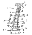
도 1은 실시예에 따른 B-필라를 측면도로 도시한다.
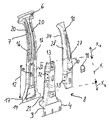
도 2는 B-필라를 분해도로 도시한다.
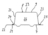
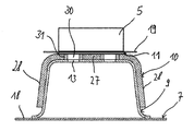
도 3은 도 1에 도시된 단면선 III-III를 따른 개략적인 횡단면도로 B-필라를 도시한다.
도 4는 도 3에 도시된 B-필라의 확대된 상세도이다.
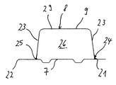
도 5는, 도 3에 도시된 것에 대한 대안인 외부 패널을 가지는, 도 1에 도시된 단면선 III-III를 따른 개략적인 횡단면도로 B-필라를 도시한다.
도 6은 도 5에 도시된 B-필라의 확대된 상세도이다.
도 7은 도 1에 도시된 단면선 VII-VII을 따른 개략적인 횡단면도로 B-필라를 도시한다.
도 8은 도 1에 도시된 단면선 VIII-VIII을 따른 개략적인 횡단면도로 B-필라를 도시한다.
도 9는, 도 8에 도시된 것에 대한 대안인 외부 패널을 가지는, 도 1에 도시된 단면선 VIII-VIII을 따른 개략적인 횡단면도로 외부 패널을 도시한다.
도 10은, 도 8에 도시된 것에 대한 추가적인 대안인 외부 패널을 가지는, 도 1에 도시된 단면선 VIII-VIII을 따른 개략적인 횡단면도로 B-필라를 도시한다.Figure 1 shows a B-pillar according to an embodiment in side view.
Figure 2 shows the B-pillar in an exploded view.
Figure 3 shows a B-pillar in a schematic cross-sectional view along section line III-III shown in Figure 1;
4 is an enlarged detail view of the B-pillar shown in Fig.
Fig. 5 shows a B-pillar in a schematic cross-sectional view along section line III-III shown in Fig. 1, with an outer panel that is an alternative to that shown in Fig.
6 is an enlarged detail view of the B-pillar shown in Fig.
Figure 7 shows a B-pillar in a schematic cross-sectional view along section line VII-VII shown in Figure 1;
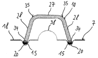
Figure 8 shows a B-pillar in a schematic cross-sectional view along section line VIII-VIII shown in Figure 1;
Fig. 9 shows an outer panel in schematic cross-sectional view along section line VIII-VIII shown in Fig. 1, with an outer panel alternative to that shown in Fig.
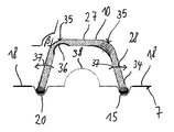
Fig. 10 shows a B-pillar in schematic cross-sectional view along section line VIII-VIII shown in Fig. 1, with an outer panel as an additional alternative to that shown in Fig.
도 1은, 중앙 필러로서 또한 지칭될 수 있는 B-필라 형태의 자동차 본체의 차량 필라를 도시한다. B-필라는, 그러한 B-필라가 자동차 본체에 내장된 조건에서, 하단으로부터 상단까지 연장되고 각부 영역(1), 중앙 영역(2) 및 머리(head) 영역(3)으로 분할될 수 있는, 세장형의 중공형 기본 구조물을 포함한다.BRIEF DESCRIPTION OF THE DRAWINGS Figure 1 shows a vehicle pillar of a B-pillar type automotive body which may also be referred to as a center pillar. The B-pillar can be divided into an
하단으로부터 시작하여 상단까지, B-필라는, 내장된 조건에서, 그 각부 영역(1)에 의해서 미도시된 차량 본체의 하단부에 연결될 수 있다. 이러한 목적을 위해서, B-필라가, 예를 들어 T-형상일 수 있고 차량 본체의 하단의 미도시된 실보드에 고정될 수 있는 하부 플랜지 부분(4)을 포함할 수 있다.From the bottom to the top, the B-pillar can be connected to the lower end of the vehicle body, not shown, by its
B-필라가 차량 본체에 내장된 조건에서, 전방 도어를 위한 결합 쐐기, 도어 결합부, 도어 힌지 또는 후방 도어 캐치를 위한 수용 요소 또는 부착 요소와 같은, 기능적 부분(5)이 B-필라의 중앙 영역(2) 내에 부착될 수 있다.In the condition that the B-pillar is embedded in the vehicle body, a functional part (5), such as a coupling wedge for the front door, a receiving element for the door coupling, a door hinge or a rear door catch, Can be attached within the region (2).
머리 영역(3)을 통해서, B-필라는, 내장된 조건에서, 차량 본체의 미도시된 지붕 영역에 부착될 수 있다. 이러한 목적을 위해서, B-필라가, 예를 들어 T-형상일 수 있고 B-필라를 차량 본체의 지붕 영역에 부착하는 역할을 하는, 상부 플랜지 부분(6)을 포함할 수 있다.Through the
도 2에서 확인될 수 있는 바와 같이, B-필라는, 차량 본체에 내장된 조건에서, 차량 내부로 대면하는 내부 패널(7), 차량 내부로부터 멀어지는 쪽으로 대면하고, 하부 형성 부분(9) 및 상부 형성 부분(10)을 가지는 다중-구성요소 외부 패널(8), 및 보강 요소(11)를 포함한다.2, the B-pillar includes an
내부 패널(7)은 길이방향 및 횡방향으로 일정한 벽 두께를 가지는 시트 스틸로 제조된 냉간-형성된 구성요소일 수 있다. 원칙적으로, B-필라에 의해서 만족시키고자 하는 요건에 따라서, 내부 패널(7)이 또한 길이방향으로 및/또는 횡방향으로 상이한 벽 두께들을 가질 수 있다. 스틸 재료가 예를 들어 냉각-압연된, 마이크로 합금 스틸 판, 예를 들어, HC 420 LA+일 수 있고, 그러한 마이크로 합금 스틸 판은, 냉간-형성에 앞서서, 양 측면에서 아연 코팅을 구비할 수 있다. 그러한 코팅된 스트립 재료가 주지의 방식으로 브랭크를 생산하기 위해서 이용될 수 있고, 그러한 브랭크는, 후속하여, 내부 패널(7)로 냉간-형성된다. "냉간 형성"은, 이러한 경우에 시트 스틸의 재결정화 보다 명확하게 낮은 온도에서의, 예를 들어 상온에서의 금속의 형성을 의미한다.The
기능적으로, 다중-구성요소 외부 패널이, 중첩 영역(12) 만을 따라서 중첩되도록 배열되고 서로 연결되는, 하부 형성 부분(9) 및 상부 형성 부분(10)에 의해서 형성된다. 다시 말해서, 하부 형성 부분(9) 및 상부 형성 부분(10)은 서로에 대해서 오프셋되도록 배열되고, 2개의 형성 부분(9, 10)이 중첩 영역(12) 내에서 서로 중첩되고 서로 상하로 배치된다. 하부 형성 부분(9)은 아래쪽으로 즉, B-필라의 제1 길이방향 연장 방향(Xu)으로 중첩 영역(12)을 넘어서서 상부 형성 부분(10)으로부터 돌출한다. 대조적으로, 상부 형성 부분(10)은, 제1 길이방향 연장 방향(Xu)에 반대되는 방향으로, 즉, B-필라의 제2 길이방향 연장 방향(Xo)으로 위쪽으로 중첩 영역(12)을 넘어서서 하부 형성 부분(9)으로부터 돌출한다. 제1 길이방향 연장 방향(Xu) 및 제2 길이방향 연장 방향(Xo) 모두가, 반대되는 방향들을 향하고 서로 평행하게 연장되는 벡터들인 것으로 이해된다. 이하에서, 하향 또는 상향 배향을 강조할 필요가 없는 경우에, 단순한 방식으로 길이방향(X)을 언급할 것이다.Functionally, a multi-component outer panel is formed by the lower forming
내부 패널(7)의 영향을 무시하면, 각부 영역(1)이 하부 형성 부분(9)에 의해서 전체적으로 결정되고, 머리 영역은 상부 형성 부분(10)에 의해서 전체적으로 결정된다. 이는, 재료 배가(doubling)가 중첩 영역(12)에서만 발생된다는 것을 의미하고, 하부 형성 부분(9)은 시트 금속 재료로 제조되고 상부 형성 부분(10)은 섬유 보강형 플라스틱으로 제조된다. 그러한 범위까지, 외부 패널(8)은, 중첩 영역(12) 내에서 보강된 하이브리드 구성요소가 된다.If the influence of the
하부 형성 부분(9)이 열간-형성되고 경화된 형성 부분일 수 있다. 하부 형성 부분(9)을 생산하기 위해서, 제1 스트립 재료, 예를 들어 22MnB5 시트 스틸로 알루미늄 규소 코팅이 제공되고 가요적으로(flexibly) 압연된다. 가요적으로 압연된 시트 스틸이 또한 테일러 롤드 브랭크로 지칭된다. 이러한 코팅된 스트립 재료으로부터, 브랭크가 그 길이방향 연장을 따라서 가변적인 벽 두께를 가지도록 그리고, 특히, 횡방향 연장을 따라서 일정한 벽 두께를 가지도록, 브랭크가 생산된다. 브랭크의 열간-형성에 앞서서, 기능적 부분, 예를 들어 전방 도어를 위한 결합 쐐기, 도어 결합부, 도어 힌지 또는 후방 도어 캐치를 위한 수용 요소 또는 부착 요소를 위한 개구부(13), 및 추가적인 개구부가 브랭크 내로 도입된다. 원칙적으로, 레이저 비임 절단에 의해서, 개구부(13)가 또한 열간-형성되고 경화된 하부 형성 부분(9) 내로 도입될 수 있다. 후속하여, 브랭크가 열간-형성되고, 열간-형성은, 본 경우에 사용된, 22MnB5의 재결정 온도 보다 높은 온도에서 재료를 형성하는 것을 의미한다. 필요한 경우에, 국소적인 연성 구역이, 경화된 하부 형성 부분(9) 내에 제공될 수 있다. 그러한 연성 구역은, 예를 들어, B-필라의 주요 파괴 영역 내에, 즉 충돌 에너지의 흡수 및 방출을 위해서 디자인된 영역 내에 제공될 수 있다. 연성 구역은, 그들의 재료 성질과 관련하여, 각각의 요건에, 예를 들어 특히 큰 파단 연성 값(fracture ductility value)에 적합화된다.The lower forming
상부 형성 부분(10)은 고강도 섬유 재료를 가지는 섬유 복합 재료로, 예를 들어 탄소 섬유 보강형 플라스틱(CFK) 또는 유리 섬유 복합 재료(GFK)로 제조된다. 섬유 복합 재료의 개별적인 섬유가 망포(scrim)로 또는 다중-축 망포로 또는 상부 형성 부분(10)의 개별적인 영역을 특히 보강하기 위한 직물로서 배열될 수 있고, 그러한 망포에서 섬유는, 이상적으로, 평행하게 그리고 연신되어(stretched) 배열되고, 다중-축 망포에서는 섬유가 라미네이트 층(laminate layer)으로만 배열되지 않고, 부가적인 섬유가 라미네이트 층에 수직으로 배향된다. "직물"은, 조방사(roving)와 같은 개별적인 섬유가 하나의 평면 내에서 연신되는 것이 아니라, 임의 트랙(track) 상에서 연신되는 것을 의미하는데, 이는 종종 복잡한 섬유 배향이 요구되기 때문이다. 상부 형성 부분(10)은 그러한 상부 형성 부분(10)의 길이방향 및/또는 횡방향으로 상이한 벽 두께들을 가질 수 있다.The upper forming
이하에서, B-필라의 구조가 구체적으로 설명된다. 내부 패널(7)은, 예를 들어 전기 케이블 또는 다른 차량 구성요소를 공급하기 위한 역할을 하는 몇 개의 함몰부(14)가 내부로 통합된, 적어도 대략적으로 평면형이고 세장형인 기본 형상을 갖는다. 내부 패널(7)의 상부 단부 영역 내에는, B-필라를 지붕 판에 부착하기 위한 상부 플랜지 부분(6)이 제공된다.Hereinafter, the structure of the B-pillars will be described in detail. The
연부의 측부 상에서, 실질적으로 2개의 측방향 플랜지-유사 지지 부분(16)이 B-필라의 길이방향(X)으로 연장된다. 지지 부분(16)은, 상부 플랜지 부분(6)으로부터 시작하여, B-필라의 중앙 영역(2)을 따라서 내부 패널(7)의 하부 단부 영역(17) 내로 연장되고, B-필라의 적어도 대략적으로 약간 곡선형인 형상을 따른다. 그에 의해서, B-필라의 횡방향에서 볼 때, 지지 부분(16)의 내부 부분이 내부 패널(7)을 외부 패널(8)에 연결하는 역할을 한다. 반면에, 플랜지-유사 지지 부분(16)의 외부 플랜지 부분(18)은 추가적인 차량 구성요소, 예를 들어 외부 외피(19)(도 7에서 단순화된 형태로 도시됨)를 내장된 조건의 B-필라에 부착하는 역할을 한다. B-필라의 머리 영역(3)에서, B-필라의 플랜지-유사 지지 부분(16)이 홈(20)을 포함하고, 그러한 홈은 B-필라의 길이방향(X)으로 적어도 실질적으로 연장되고 및/또는 B-필라의 약간 곡선화된 경로를 적어도 대략적으로 따른다. 홈(20)은 내부 패널(7)을 외부 패널(8)의 상부 형성 부분(10)에 연결하는 역할을 한다.On the side of the edge, substantially two lateral flange-
B-필라의 각부 영역(1) 내에서 그리고 중앙 영역(2) 내에서, 내부 패널(7) 및 외부 패널(8)의 하부 형성 부분(9)이 서로에 대해서 적어도 재료-결합식으로(material-lockingly) 연결된다. 도 1 및 도 2에서, 외부 패널(8)의 하부 형성 부분(9)이 대략적으로 T-형상이라는 것을 확인할 수 있다. B-필라를 차량 본체의 베이스에 부착하기 위한 하부 플랜지 부분(4)이 하부 형성 부분(9)의 하부 단부 영역 내에 제공된다. In the
도 3은 도 1에 도시된 단면선 III-III를 따른 B-필라의 횡단면도를 도시한다. 하부 형성 부분(9)이 하부 플랜지 부분(4) 위에서 U-형상의 또는 모자-형상의 횡단면을 갖는다는 것을 확인할 수 있다. 그에 의해서, 하부 형성 부분(9)의 연결 연부(21)가 내부 패널(7)의 외부 연부(22)에 대해서 오프셋되고, 그에 따라 내부 패널(7)은 지지 부분(16)의 외부 플랜지 부분(18) 내에서 B-필라의 단일-층 플랜지 부분을 형성한다. 구체적으로, 모자-형상의 하부 형성 부분(9)이 2개의 굽혀진 용접 부분(24)을 가지는 그 측벽(23)에 의해서 내부 패널(7) 상에서 지지되고, 그러한 2개의 굽혀진 용접 부분(24)은 하부 형성 부분(9)을 위한 브랭크를 열간-형성하는 프로세스 중에 발생되는 인입된(drawn-in) 플랜지를 절단하는 것에 의해서 생성될 수 있다.Figure 3 shows a cross-sectional view of a B-pillar along section line III-III shown in Figure 1; It can be seen that the lower forming
도 4의 확대된 부분적인 도면에서, 내부 패널(7)을 향한 2개의 용접 부분(24)의 경사진 위치의 결과로서, 하부 형성 부분(9)이 길이방향(X)으로 실질적으로 연장되는 2개의 연결 연부(21)를 따라서만 내부 패널(7)과 접촉된다는 것이 확인될 수 있다. 연결 연부(21)가 내부 패널(7)의 외부 연부(22)에 대해서 후퇴되고, 그 결과로서 내부 패널(7)의 플랜지-유사 지지 부분(16)의 플랜지 부분(18)이 노출되고, 다시 말해서 외부 패널(8)에 의해서 커버되지 않는다. 그에 따라, B-필라의 각부 영역(1) 내에서 그리고 중앙 영역(2) 내에서 지지 부분(16)의 외부 플랜지 부분(18)을 따라서, 특히 도 3 내지 도 7에 도시된 바와 같이, B-필라가 단일-층 디자인이다. B-필라를 추가적인 차량 구성요소에, 예를 들어 외부 외피(19)에, 지붕에, 또는 유리 표면에 접합할 수 있게 하기 위해서, 단지 내부 패널(7)이 단일-층 플랜지 부분(18)을 따라서 추가적인 차량 구성요소의 외부 패널(8)에 접합되거나 달리 고정되면 된다. 이러한 것은 예를 들어 용접이나 접착에 의해서 이루어질 수 있다.4, as a result of the inclined position of the two welded
내부 패널(7) 및 하부 형성 부분(9)이, 연속적인 고에너지 용접부(25), 간단히 용접부에 의해서, 레이저 비임 용접 프로세스에 의해 하부 형성 부분(9)의 2개의 연결 연부(21)를 따라서 함께 연결된다. 용접부(25)가 각각의 연결 연부(21)의 전체 연부 길이를 따라서 연장될 수 있다. 하부 형성 부분(9)과 내부 패널(7) 사이의, 내부 패널(7) 상의 2개의 용접 부분(24)의 경사진 배열로 인해서, 예를 들어 15°의 협각(α)이 존재하고, 그에 따라 B-필라의 내부로 개방되는 내부 공간(26)이 형성된다. 내부 공간(26)이 용접 동작 중에 방출되는 금속 증기를 탈가스시키는 역할을 한다. 상부 형성 부분(10)이 아직 부착되지 않은 시점에, 금속 증기가 하부 형성 부분(9)의 상부 및 하부 단부 영역에서 빠져 나올 수 있다.The
좁은 용접 부분(24)으로 인해서 약간만 중첩되는 내부 패널(7) 및 하부 형성 부분(9)의 장점은, 하부 형성 부분(9)의 상이한 벽 두께들이 내부 패널(7)의 시트 두께에 상응할 필요가 없다는 것이다. 결과적으로, 용접 프로세스뿐만 아니라 B-필라를 위한 계획 및 생산 프로세스가 단순화된다. 이는, 내부 패널(7)이, 균일한 판 두께를 가지는, 시장에서의 표준화된 폐쇄 판일 수 있다는 것을 의미한다. 이어서, 단지 하부 형성 부분(9)이 충돌 보호 조건을 위한 적용예- 및 시장-특정의 재원(application- and market-specific specification)에 적합화되기만 하면 되고, 시트 두께를 증가 또는 감소시키는 것에 의해서 하부 형성 부분(9)의 특정의 부분적 영역이 구체적으로 보강되거나 보다 연성으로 제조된다. The advantages of the
도 5 및 도 6은 각각 B-필라의 대안적인 횡단면을 도시한다. 도 3 및 도 4에 도시된 실시예와 대조적으로, 하부 형성 부분(9)을 열간-형성하는 프로세스 중에 일반적으로 발생되는 인입된 플랜지가, 프레스 경화 이후에, 완전히 절단되었다. 이러한 방식으로, 하부 형성 부분(9)은 U-형상의 횡단면의 기본 형상을 수용하고, 2개의 용접 부분(24)이 측벽(23)의 외부 연부 영역에 형성된다. 도 6은, 용접 부분(24)의 폭이 용접부(25)의 폭으로 제한되고, 그에 따라 용접부 부분(24)의 폭이 2 밀리미터 미만의 범위를 가질 수 있다는 것을 보여 준다. 그에 따라, 하부 형성 부분(9)은, 내부 패널(7)에 대해서, 접경할 때, 레이저 비임 용접 프로세스에 의해서 약 80°의 각도(α)로 접합되고 2개의 연결 연부(21)를 따라서 내부 외피(7)에 접합된다. 다시, 이러한 경사진 배열로 인해서, B-필라의 내측부 내로 개방된 내부 공간(26)이 용접 동작 중에 방출되는 금속 증기를 탈가스시키는 역할을 한다.Figures 5 and 6 show alternative cross-sections of a B-pillar, respectively. In contrast to the embodiment shown in Figs. 3 and 4, the entrained flange, which generally occurs during the process of hot-forming the lower forming
중첩 영역(12)에서, 상부 형성 부분(10)이 하부 형성 부분(9) 상의 외측부로부터 형상-결합식으로 배치되고 하부 형성 부분(9)으로 재료-결합식으로 그리고 강제-결합식으로(force-lockingly) 연결되며, 설명된 바와 같이, 하부 형성 부분(9)은 내부 패널(7)로 적어도 재료-결합식으로 연결된다.In the
상부 형성 부분(10)이 U-형상의 횡단면을 가지는 세장형의 기본 형상을 갖는다. 구체적으로, 상부 형성 부분(10)이 외부 벽(27) 및 2개의 측벽(28)을 가지며, 그러한 2개의 측벽은, 도 7에 도시된 바와 같이, 내부 패널(7)로부터 거리를 두고 배열된다. 상부 형성 부분(10)은, 중첩 영역 내에서, 하부 형성 부분(9)의 외측부와 평면형으로 접촉한다. 상부 형성 부분(10)과 하부 형성 부분(9) 사이에서, 접촉 침식을 방지하기 위해서, 차단 층(미도시)이 배열될 수 있다.The
도 2에서 확인될 수 있는 바와 같이, 중첩 영역(12)의 길이방향 연장부가 상부 형성 부분(10)의 길이방향 연장부의 약 50% 내지 60%이고 상부 형성 부분(10)의 길이방향 연장부의 약 35% 내지 45%이다. 승객 보호와 관련하여, 차량 본체는 특히 B-필라의 중앙 영역(2) 내에서 일반적으로 경직성을 갖도록 디자인되고, B-필라의 중첩 영역(12)이 B-필라의 중앙 영역(2) 내에 적절히 형성될 수 있다. 원칙적으로, 차량 본체가 충족켜야 하는 요건에 따라서, 중첩 영역(12)이 B-필라의 각부 또는 머리 영역(1, 3) 내에 형성될 수 있고 및/또는 몇 개의 영역(1, 2, 3)에 걸쳐 연장되는 것이 가능하고 고려될 수 있다.2, the lengthwise extension of the
설명된 형상-결합 이외에, 하부 형성 부분(9) 및 상부 형성 부분(10)이 또한 재료- 또는 강제-결합식으로 서로 연결된다. 재료-결합 연결을 생성하기 위해서, 2개의 형성 부분(9, 10)이 중첩 영역(12) 내에서 서로 접착된다. 도 7은, 하부 형성 부분(9) 및 상부 형성 부분(10)이, 고정 요소(미도시)에 의해서, 예를 들어 나사 또는 리벳에 의해서, 중첩 영역(12) 내에서 강제-결합식으로 연결된다는 것을 보여 준다. 고정 요소는 전방 도어를 위한 결합 쐐기, 도어 결합부, 도어 힌지 또는 후방 도어 캐치를 위한 수용 요소 또는 부착 요소와 같은 기능적인 부분(5)을 부착하도록 구성된다.In addition to the described shape-bonding, the lower forming
고정 요소를 수용하기 위해서, 상부 형성 부분(10) 및 하부 형성 부분(9)이, 서로 중첩되는 외부 벽(27, 29) 내에서 커버링 개구부(30, 13)를 갖는다. 또한, 고정 요소와 상부 형성 부분(10) 사이의 접촉 침식을 방지하기 위해서, 슬리브(31)가 상부 형성 부분(10)의 개구부(30) 내로 삽입된다. 슬리브(31)가, 예를 들어, 바니시 처리될(varnished) 수 있거나, 티타늄이나 다른 내식성 재료로 제조될 수 있다. 또한, 중첩 영역(12) 내에서, 내부 패널(7)로부터 멀어지는 쪽으로 대면하는 상부 형성 부분(10)의 외부 면 상에, 고정 요소를 지지하기 위한 시트 금속으로 제조된 보강 요소(11)가 배열될 수 있다. 이러한 방식으로, 충돌 에너지가 도입될 때, 예를 들어 측면 충돌의 경우에, 고정 요소가 외부 패널(8) 및 섬유 보강형 플라스틱으로 제조된 상부 형성 부분(10)을 통해서 가압되는 것이 방지되고, 사실상 상부 형성 부분(10)의 천공이 방지된다. 보강 요소(11)가, 조각(patch)으로서 또한 지칭될 수 있는 시트 금속 단편으로 제공될 수 있다. 이러한 목적을 위해서, 보강 요소(11)가 시트 금속으로부터, 특히 스틸 판으로부터 생산될 수 있다. 보강 요소(11)와 상부 형성 부분(10) 사이에, 접촉 침식을 방지하기 위한 차단 층(미도시)이 또한 제공될 수 있다. 또한, 중첩 영역 내에서, 하부 형성 부분(9) 및 상부 형성 부분(10)이, 강제-결합 방식으로 2개의 형성 부분(9, 10)을 또한 연결할 수 있는 추가적인 고정 요소를 수용하기 위한, 측벽(23, 28) 내의 관통-개구부(32, 33)를 포함할 수 있다.To accommodate the fastening elements, the upper forming
도 8은, B-필라의 머리 영역(3) 내에 위치된, 도 1에 도시된 단면선 XIII-XIII를 따른 B-필라의 횡단면도를 도시한다. 중첩 영역(12) 위에서, 상부 형성 부분(10)이 내부 패널(7)에 직접적으로 형상-결합식으로 연결되는 것이 확인될 수 있다. 상부 플랜지 부분(6) 내에서, 상부 형성 부분(10)이, 예를 들어 리벳형 연결(구체적으로 도시되지 않음)에 의해서 그리고 중앙 영역(2)에서 예를 들어 기능적 부분(5)을 B-필라에 고정하는 리벳형 연결에 의해서 뿐만 아니라, 하부 형성 부분(9)에 대한 연결에 의해서 내부 패널(7)에 고정될 수 있다. 상부 형성 부분(10)의 측벽(28)의 연부 영역에서, 내부 패널(7)의 홈(20) 내로 형상-결합식으로 결합되는 연결 부분(34)이 형성된다. 재료-결합 연결을 생성하기 위해서, 홈(20) 내의 연결 부분(34)이 접착 비드(15)에 의해서 내부 패널(7)에 접착될 수 있다. 이러한 방식으로, 상부 형성 부분(10)이 B-필라의 머리 영역(3) 내에서 내부 패널(7)에 고정된다.Figure 8 shows a cross-sectional view of a B-pillar along section line XIII-XIII shown in Figure 1, located in the
도 9는, 상부 형성 부분(10)의 연결 부분(34')이 또한 상부 형성 부분(10)의 굽혀진 연부 영역으로서 제공될 수 있다는 것을 도시한다. 상부 형성 부분(10)의 연결 부분(34')을 형성하는 굽혀진 또는 위로-굽혀진(bent or bent-over) 연부 영역에 의해서, 인장 응력을 받는 상부 형성 부분(10)의 연부 영역이 보강되고 노치 민감성(notch sensitivity)이 감소된다.9 shows that the connecting portion 34 'of the upper forming
또한, 도 8 및 도 10에서, 상부 형성 부분(10)의 측벽(28)과 외부 벽(27) 사이에 약 110°의 협각(β)이 존재한다는 것이 확인될 수 있다. 이러한 방식으로, 외측으로부터 외부 패널(8) 상으로 힘이 작용하는 경우에, 특히 충돌 충격으로부터 초래되는 충돌 에너지가 도입되는 경우에, 상부 형성 부분(10)의 외부 벽(27)이 그러한 외부 벽(27)과 내부 패널(7) 사이의 구성-관련된 거리의 10%까지 내부 패널(7)을 향해서 탄성적으로 탄력적일 수 있다. 결과적으로, 머리 영역(3) 내의 B-필라가 스프링과 유사하게 구성되고, 탄력적인 영역 내에서, 변형 가능한 기본 형상을 갖는다.8 and 10, it can be confirmed that there is a coarse angle? Of about 110 占 between the
충돌 에너지가 도입되는 경우에 상부 형성 부분(10)의 탄력도(springiness)를 개선하기 위해서, 즉 상부 형성 부분(10)이 보다 많은 에너지를 흡수하도록 하기 위해서, 도 8에서, 내부 패널(7)이 상부 형성 부분(10)의 측벽들(38) 사이에 배열된 재료 약화 부분(38)을 포함하는 것을 확인할 수 있을 것이다. 약화 부분(38)이 B-필라의 제2 길이방향 연장 방향(Xo)으로 중첩 영역(12) 위에서 연장된다. 이는, 측면 충돌의 경우에, 내부 패널(7)의 홈(20)과 결합되는 측벽(28)인, 적어도 부분적으로 U-형상인 상부 형성 부분(10)의 측벽(28)이 내부 패널(7)에 대해서 상대적으로 직립된다는 것, 즉 측벽(28)들의 길이방향 자유 단부들 사이의 거리가 감소된다는 것을 의미한다. 만약 도입된 충돌 에너지가 상부 형성 부분(10)의 파단 힘 미만에서 유지된다면, 상부 형성 부분(10)의 측벽(28)이, 부하가 제거된 후에, 외측으로 다시 이동될 수 있고, 즉 측벽들의 길이방향 자유 단부들 사이의 거리가 다시 증가된다. 결과적으로, 상부 형성 부분(10)이 파괴 없이 "존속될(breath)" 수 있다. 이어서, 약화 부분(38)을 따라서, 내부 패널(7)이, 내부 패널(7)의 홈(20)과 결합되는 길이방향 자유 단부를 외향으로 이동시키는 것에 의해서 다시 멀리 당겨지고, 상부 형성 부분(10)이 수용 에너지를 방출한다.In order to improve the springiness of the upper forming
또한, 도 8 및 도 10은, 추가적인 차량 구성요소, 예를 들어 외부 외피(19), 유리 표면 또는 지붕을 단순한 방식으로 접합할 수 있게 하기 위해서, 내부 패널(7)의 외부 플랜지 영역(18)이, B-필라의 각부 영역(1) 및 중앙 영역(2)과 유사하게, 단일-층형인 것을 도시한다.8 and 10 illustrate the
도 10은, 도 1에 도시된 단면 선 XIII-XIII을 따른 B-필라를 통한 횡단면도를 참조하여 B-필라의 추가적으로 가능한 실시예를 도시한다. 머리 영역(3) 내에서 B-필라의 충돌 거동에 영향을 미치기 위한 목적을 위해서, 상부 형성 부분(10)이, 외부 벽(27)과 측벽(28) 사이의 전이 영역(35) 내에서, 노치(36) 형태의 접합부-유사 재료 약화부를 포함한다는 것이 확인될 수 있고, 그러한 재료 약화부는, 차이점을 명료화하기 위한 목적을 위해서, 도 10의 도면에서, 좌측에 배치되는 전이 영역 내에서만 도시되어 있다. 양 전이 영역(35) 내에서 상부 형성 부분(10)을 구체적으로 약화시키는 것에 의해서, 외측으로부터 도입되는 힘이 B-필라에 작용하는 경우에, B-필라의 스프링 거동을 조정할 수 있다. 그에 따라, 측면 충돌의 경우에, 상부 형성 부분(10)의 외부 벽(27)이 내부 패널(7)을 향해서 가압될(pushed) 수 있고, 측벽(28)이 내부 패널(7)에 대해서 화살표(37)의 방향으로 직립되어 유지된다는 점에서 측벽(28)이 굴복될 수 있다.10 shows a further possible embodiment of a B-pillar with reference to a cross-sectional view through a B-pillar according to the cross-sectional line XIII-XIII shown in Fig. For the purpose of influencing the collision behavior of the B-pillar in the
재료 약화부, 본 경우에 노치(36)가, 도 10에 도시된 바와 같이, 도 8에 따른 직선형 연결 부분(34)과 그리고 도 9에 도시된 바와 같은 굽혀진 연결 부분(34')과 조합될 수 있다.The material weakening portion, in this case the
또한, 도 10에 도시된 바와 같이, 상부 형성 부분(10)의 측벽들(28) 사이에 배열되고 B-필라의 제2 길이방향 연장 방향(Xo)으로 중첩 영역(12) 위에서 연장되는, 재료가 약화된 부분이 제시된다.In addition, as shown in Figure 10, which is arranged between the
B-필라를 생산하기 위해서, 특히, 다른 용접 프로세스에 비해서 적은 양의 그리고 보다 집중된 형태의 열 에너지를 접합하고자 하는 구성요소로 도입하는 고에너지 비임 용접 프로세스에 의해서, 하부 형성 부분(9)을 내부 패널(7)에 먼저 연결하는 것이 바람직하다. 하부 형성 부분(9)의 연결 연부(21)가 내부 패널(7)의 외부 연부(22)에 대해서 오프셋되기 때문에, 일 측부로부터 연결 연부(21)에 용이하게 도달할 수 있고, 그 결과로서, 고에너지 비임 용접 프로세스의 적용이 단순화된다. 고에너지 비임 용접 프로세스로서, 전기 아크 및 전자 비임 용접 프로세스 이외에, 레이저 비임 용접 프로세스가 특히 적합하고, 선택된 용접 프로세스가 임의의 부가적인 재료와 함께 또는 그러한 재료가 없이 실행될 수 있다. 고에너지 비임 용접부(25)가 연결 연부(21)의 연부 길이의 적어도 50%를 따라서 생성되고, 연속적인 또는 간헐적인 용접부를 생성할 수 있다.By the high energy beam welding process, which introduces a small amount and more concentrated form of thermal energy to the component to be bonded, in particular to produce a B-pillar, compared to other welding processes, It is preferable to connect to the
하부 형성 부분(9)이 내부 패널(7)에 연결된 후에, 상부 형성 부분(10)이 하부 형성 부분(9) 및 내부 패널(7) 상으로 배치되고, 그에 따라, 한편으로, 하부 형성 부분(9) 및 상부 형성 부분(10)이 중첩 영역(12)만을 따라서 서로 중첩되도록 그리고, 다른 한편으로, 상부 형성 부분(10)이 내부 패널(7) 상에서 머리 영역(3) 내에서 지지된다. 또한, 상부 형성 부분(10)이 평면형 방식으로 하부 형성 부분(9)에 그리고 홈(20) 내에서 내부 패널(7)에 접착된다. After the lower forming
후속하여, B-필라가 차량 본체에 고정될 수 있고, 특히 용접 프로세스에 의해서, 하부 플랜지 부분(4)이 차량 본체의 베이스에 부착되고 상부 플랜지 부분(6)이 차량 본체의 지붕 영역에 부착된다. 원칙적으로, 상부 형성 부분(10)이 이시점에서만(only now) 하부 형성 부분(9) 상에 배치될 수 있고 그러한 하부 형성 부분(9)에 연결될 수 있다.Subsequently, the B-pillar can be secured to the vehicle body, and in particular by means of a welding process, the
기능적 부분(5)이 B-필라에 부착되자 마자, 또한 상부 형성 부분(10) 및 하부 형성 부분(9)이, 개구부(30, 23)와 결합되는 고정 요소에 의해서 서로 강제-결합식으로 연결된다.As soon as the
1; 각부 영역
2; 중앙 영역
3; 머리 영역
4; 하부 플랜지 부분
5; 기능적 부분
6; 상부 플랜지 부분
7; 내부 패널
8; 외부 패널
9; 하부 형성 부분
10; 상부 형성 부분
11; 보강 요소
12; 중첩 영역
13; 개구부
14; 함몰부
15; 접착 비드
16; 지지 부분
17; 하부 단부 영역
18; 플랜지 부분
19; 외부 외피
20; 홈
21; 연결 연부
22; 외부 연부
23; 측벽
24; 용접 부분
25; 용접부
26; 내부
27; 외부 벽
28; 측벽
29; 외부 벽
30; 개구부
31; 슬리브
32; 개구부
33; 개구부
34, 34'; 연결 부분
35; 전이 영역
36; 노치
37; 화살표
38; 약화된 재료 부분
α; 각도
β; 각도
Xu; 제1 길이방향 연장 방향
Xo; 제2 길이방향 연장 방향
X; 길이방향One; Each area
2; Central area
3; Head area
4; Bottom flange portion
5; Functional part
6; Upper flange portion
7; Inner panel
8; Outer panel
9; Bottom forming part
10; The upper forming portion
11; Reinforcing element
12; Overlap area
13; Opening
14; Depression
15; Adhesive bead
16; Support portion
17; Lower end region
18; Flange portion
19; Outer sheath
20; home
21; Connection edge
22; External edge
23; Side wall
24; Welding part
25; Weld
26; inside
27; Outer wall
28; Side wall
29; Outer wall
30; Opening
31; sleeve
32; Opening
33; Opening
34, 34 '; Connecting portion
35; Transition region
36; Notch
37; arrow
38; Weakened part of the material
alpha; Angle
beta; Angle
X u ; The first longitudinal direction extending direction
X is o ; The second longitudinal direction extending direction
X; Lengthwise
Claims (15)
시트 금속 재료로 제조된 내부 패널(7) 및 상기 내부 패널(7)에 연결된 다중-구성요소 외부 패널(8)을 포함하고, 상기 외부 패널(8)은 시트 금속 재료로 제조된 하부 형성 부분(9) 및 섬유 보강형 플라스틱으로 제조된 상부 형성 부분(10)을 포함하고, 상기 2개의 형성 부분(9, 10)은 서로 중첩되도록 중첩 영역(12)을 따라서 배열되고, 상기 하부 형성 부분(9)이 상기 B-필라의 제1 길이방향 연장 방향(Xu)으로 상기 중첩 영역(12)을 넘어서서 상기 상부 형성 부분(10)으로부터 돌출하도록 그리고 상기 상부 형성 부분(10)이 상기 B-필라의 제2 길이방향 연장 방향(Xo)으로 상기 중첩 영역(12)을 넘어서서 상기 하부 형성 부분(9)으로부터 돌출하도록 서로 연결되는, B-필라.B-pillar for automobile body,
And an outer panel (8) connected to said inner panel (7), said outer panel (8) comprising a lower forming portion (8) made of a sheet metal material 9) and a top forming portion (10) made of fiber-reinforced plastic, the two forming portions (9, 10) being arranged along the overlapping area (12) ) of the B- in a first longitudinal extension direction (X u) of the pillar beyond the overlapping region 12 and so as to protrude from the upper forming portion 10 forming the upper portion 10 is the B- pillar claim 2, B- pillar longitudinal extension direction (X o) to beyond the overlapping region 12 are connected to each other so as to protrude from the lower forming part (9).
상기 중첩 영역(12)의 길이방향 연장부가 상기 하부 형성 부분(9)의 길이방향 연장부의 70% 보다 짧고 및/또는 상기 상부 형성 부분(10)의 길이방향 연장부의 50% 보다 짧은 것을 특징으로 하는 B-필라.The method according to claim 1,
Characterized in that the longitudinal extension of the overlap region (12) is shorter than 70% of the longitudinal extension of the lower forming portion (9) and / or shorter than 50% of the longitudinal extension of the upper forming portion B-pillar.
상기 중첩 영역(12) 내에서, 상기 하부 형성 부분(9) 및 상기 상부 형성 부분(10)이 서로 재료-결합식으로 그리고 강제-결합 식으로 연결되는 것을 특징으로 하는 B-필라.3. The method according to claim 1 or 2,
Characterized in that in the overlap region (12), the lower forming portion (9) and the upper forming portion (10) are connected to each other in a material-binding manner and in a forced-bonding manner.
상기 중첩 영역(12) 내에서, 상기 하부 형성 부분(9) 및 상기 상부 형성 부분(10)이 고정 요소에 의해서 서로 강제-결합 식으로 연결되고, 상기 고정 요소가 상기 B-필라에서 유지되는 기능적 부분(5)을 부착하도록 구성되는 것을 특징으로 하는 B-필라.4. The method according to any one of claims 1 to 3,
In the overlap region 12, the lower forming portion 9 and the upper forming portion 10 are connected to each other by a fixing element in a forced-bonding manner, and the fixing element is functionally (5). ≪ Desc / Clms Page number 12 >
상기 중첩 영역(12) 내에서, 상기 내부 패널(7)로부터 멀어지는 쪽으로 대면하는 상기 상부 형성 부분(10)의 외부 면 상에, 상기 고정 요소 중 적어도 하나를 지지하기 위한 시트 금속 재료로 제조된 보강 요소(11)가 배열되는 것을 특징으로 하는 B-필라.5. The method of claim 4,
On the outer surface of the upper forming portion (10) facing away from the inner panel (7) in the overlap region (12), a reinforcement made of a sheet metal material for supporting at least one of the fixing elements Characterized in that the elements (11) are arranged.
상기 내부 패널(7)이 적어도 대략적으로 상기 제2 길이방향 연장 방향(Xo)으로 연장되는 지지 부분(16)을 포함하고, 상기 상부 형성 부분(10)이 상기 지지 부분(16)으로의 연결을 위한 상응하는 연결 부분(34; 34')을 포함하고, 상기 내부 패널(7) 및 상기 상부 형성 부분(10)이 상기 중첩 영역(12) 외부에서 서로 형상-결합식으로 연결되는 것을 특징으로 하는 B-필라.6. The method according to any one of claims 1 to 5,
Characterized in that said inner panel (7) comprises a support part (16) extending at least approximately in said second longitudinal direction ( Xo ), said upper forming part (10) being connected to said support part Characterized in that the inner panel (7) and the upper forming portion (10) are connected in a shape-and-coupling manner to each other outside the overlap region (12) B-pillar.
상기 중첩 영역(12)의 외부에서, 상기 지지 부분(16)이 홈(20)을 포함하고, 상기 상부 형성 부분(10)의 연결 부분(34; 34')이 상기 홈 내에 형상-결합식으로 고정되는 것을 특징으로 하는 B-필라.The method according to claim 6,
Outside the overlap region 12, the support portion 16 includes a groove 20 and the connecting portion 34 (34 ') of the upper forming portion 10 is shaped- Wherein the B-pillar is fixed.
상기 상부 형성 부분(10)의 연결 부분(34')이 상기 상부 형성 부분(10)의 굽혀진 연부 영역으로서 제공되는 것을 특징으로 하는 B-필라.8. The method according to claim 6 or 7,
Wherein a connecting portion (34 ') of the upper forming portion (10) is provided as a bent bent edge region of the upper forming portion (10).
상기 중첩 영역(12)의 외부에서, 적어도 부분적으로, 상기 상부 형성 부분(10)이 U-형상의 횡단면을 갖고, 상기 상부 형성 부분(10)은, 외부로부터 상기 외부 패널(8) 상으로 힘이 작용할 때, 상기 상부 형성 부분(10)의 외부 벽(27)이 상기 내부 패널(7)을 향해서 상기 외부 벽(27)과 상기 내부 패널(7) 사이의 구성-관련 거리의 10%까지 탄력적으로 유지되도록(resiliently suspended) 구성되는 것을 특징으로 하는 B-필라.9. The method according to any one of claims 1 to 8,
Wherein the upper forming portion (10) has a U-shaped cross section at least partially outside the overlap region (12) and the upper forming portion (10) has a force The outer wall 27 of the upper forming portion 10 is resiliently biased toward the inner panel 7 by up to 10% of the configuration-related distance between the outer wall 27 and the inner panel 7. [ Wherein the B-pillar is resiliently suspended.
상기 적어도 부분적으로 U-형상인 상부 형성 부분(10)의 연결 부분(34; 34')이 상기 상부 형성 부분(10)의 2개의 측벽(28)의 연부 영역에 형성되고, 상기 외부 벽(27)과 상기 각각의 측벽(28) 사이에, 100°내지 170° 범위의 협각(β)이 존재하는 것을 특징으로 하는 B-필라.10. The method of claim 9,
The connecting portion 34 (34 ') of the at least partially U-shaped top forming portion 10 is formed in the edge region of the two side walls 28 of the upper forming portion 10 and the outer wall 27 ) And the respective side wall (28), there is a narrow angle (?) In the range of 100 ° to 170 °.
상기 외부 벽(27)과 상기 측벽(28) 사이의 전이 영역(35)에서, 상기 상부 형성 부분(10)이 접합부-유사 재료 약화부, 노치(36) 또는 좌굴 지역을 포함하는 것을 특징으로 하는 B-필라.11. The method of claim 10,
Characterized in that in the transition region (35) between the outer wall (27) and the side wall (28), the upper forming portion (10) comprises a joint-like material weakening portion, a notch (36) B-pillar.
상기 내부 패널(7)이, 상기 상부 형성 부분(10)의 측벽들(28) 사이에 배열되고 상기 B-필라의 제2 길이방향 연장 방향(Xo)으로 상기 중첩 영역(12) 위에서 연장되는, 재료 약화 부분(38)을 포함하는 것을 특징으로 하는 B-필라.12. The method according to any one of claims 1 to 11,
The inner panel 7, the side walls (28) extending the second length direction of the array and the B- pillar between the direction (X o) of the top forming portion (10) extending from above the overlap region (12) , Material weakening portion (38).
상기 하부 형성 부분(9)이 상기 내부 패널(7)에 연결되기 위한 적어도 하나의 용접 부분(24)을 포함하고, 상기 하부 형성 부분(9) 및 상기 내부 패널(7)이 용접부(25)에 의해서 서로 연결되고, 상기 하부 형성 부분(9)의 연결 연부(21)가 상기 내부 패널(7)의 외부 연부(22)로부터 이격되고, 그에 따라 상기 내부 패널(7)이 상기 연결 연부(21)와 상기 외부 연부(22) 사이에서 상기 B-필라의 단일-층형 플랜지 부분(18)을 형성하는 것을 특징으로 하는 B-필라.13. The method according to any one of claims 1 to 12,
Characterized in that the lower forming part (9) comprises at least one welding part (24) for connecting to the inner panel (7) and the lower forming part (9) and the inner panel (7) And the connecting edge portion 21 of the lower forming portion 9 is spaced from the outer edge 22 of the inner panel 7 so that the inner panel 7 is connected to the connecting edge 21, Pillar < / RTI > single-layered flange portion (18) between the outer edge (22) and the outer edge (22).
시트 금속 재료로 제조된 내부 패널(7)을 제공하는 단계;
시트 금속 재료로 제조된 하부 형성 부분(9)을 제공하는 단계;
섬유 보강형 플라스틱으로 제조된 상부 형성 부분(10)을 제공하는 단계;
상기 하부 형성 부분(9)을 상기 내부 패널(7)에 연결하는 단계;
상기 2개의 형성 부분(9, 10)이 중첩 영역(12)에서만 서로 중첩되도록 상기 상부 형성 부분(10)을 상기 하부 형성 부분(9) 상에 배치하는 단계로서, 상기 하부 형성 부분(9)이 상기 B-필라의 제1 길이방향 연장 방향(Xu)으로 상기 중첩 영역(12)을 넘어서서 상기 상부 형성 부분(10)으로부터 돌출하고 상기 상부 형성 부분(10)이 상기 B-필라의 제2 길이방향 연장 방향(Xo)으로 상기 중첩 영역(12)을 넘어서서 상기 하부 형성 부분(9)으로부터 돌출하는, 상기 상부 형성 부분(10)을 상기 하부 형성 부분(9) 상에 배치하는 단계; 및
상기 중첩 영역(12)에서 상기 상부 형성 부분(10)을 상기 하부 형성 부분(9)과 연결하는 단계를 포함하는, 프로세스.It is the process of producing B-pillar for automobile body:
Providing an inner panel (7) made of sheet metal material;
Providing a lower forming portion (9) made of a sheet metal material;
Providing a top forming portion (10) made of fiber reinforced plastic;
Connecting the lower forming portion (9) to the inner panel (7);
Disposing the upper forming portion (10) on the lower forming portion (9) so that the two forming portions (9, 10) overlap each other only in the overlapping region (12) Pillar extending beyond the overlapping region (12) in a first longitudinal direction (X u ) of the B-pillar and projecting from the upper forming portion (10) and the upper forming portion (10) Disposing the upper forming portion (10) on the lower forming portion (9), which protrudes from the lower forming portion (9) beyond the overlap region (12) in the direction extension direction (X o ); And
And connecting the upper forming portion (10) with the lower forming portion (9) in the overlap region (12).
상기 상부 형성 부분(10)이, 적어도 부분적으로, 상기 하부 형성 부분(9)에 형상-결합식으로 연결되는 것을 특징으로 하는 프로세스.
15. The method of claim 14,
Characterized in that the upper forming part (10) is at least partly connected to the lower forming part (9) in a shape-coupling manner.
Applications Claiming Priority (2)
| Application Number | Priority Date | Filing Date | Title |
|---|---|---|---|
| DE102015115439.0 | 2015-09-14 | ||
| DE102015115439.0A DE102015115439B3 (en) | 2015-09-14 | 2015-09-14 | B-pillar for a vehicle body and method for manufacturing a B-pillar |
Publications (1)
| Publication Number | Publication Date |
|---|---|
| KR20170032192A true KR20170032192A (en) | 2017-03-22 |
Family
ID=56926059
Family Applications (1)
| Application Number | Title | Priority Date | Filing Date |
|---|---|---|---|
| KR1020160116993A KR20170032192A (en) | 2015-09-14 | 2016-09-12 | B-pillar for a motor vehicle body and process of producing a b-pillar |
Country Status (6)
| Country | Link |
|---|---|
| US (1) | US10065683B2 (en) |
| EP (1) | EP3150466B1 (en) |
| JP (1) | JP6573856B2 (en) |
| KR (1) | KR20170032192A (en) |
| CN (1) | CN106515862B (en) |
| DE (1) | DE102015115439B3 (en) |
Cited By (2)
| Publication number | Priority date | Publication date | Assignee | Title |
|---|---|---|---|---|
| CN108791504A (en) * | 2018-06-13 | 2018-11-13 | 芜湖恒信汽车内饰制造有限公司 | A kind of body structure and the center body pillar with the structure and body C pillar |
| KR20220075120A (en) | 2020-11-27 | 2022-06-07 | 서진산업 주식회사 | Bpillar with embossing pattern for increasing of stiffness |
Families Citing this family (20)
| Publication number | Priority date | Publication date | Assignee | Title |
|---|---|---|---|---|
| DE102013007805A1 (en) * | 2013-05-07 | 2014-11-13 | Daimler Ag | Pillar for a car body shell structure, method for the production of a pillar and motor vehicle bodyshell structure |
| US10633031B2 (en) * | 2015-12-18 | 2020-04-28 | Autotech Engineering S.L. | B-pillar central beam and method for manufacturing |
| DE102016201036A1 (en) * | 2016-01-26 | 2017-07-27 | Zf Friedrichshafen Ag | Method for producing a component and component produced by this method |
| US10124833B2 (en) * | 2016-09-01 | 2018-11-13 | Ford Global Technologies, Llc | B-pillar assembly for vehicle body |
| DE102016118366A1 (en) * | 2016-09-28 | 2018-03-29 | Bayerische Motoren Werke Ag | STRUCTURAL COMPONENT FOR A MOTOR VEHICLE BODY |
| KR101866080B1 (en) * | 2016-10-31 | 2018-06-11 | 현대자동차주식회사 | Shock absorption structure of reinforce for center pillar |
| JP6555303B2 (en) * | 2017-07-28 | 2019-08-07 | マツダ株式会社 | Vehicle side body structure |
| JP6898169B2 (en) * | 2017-08-02 | 2021-07-07 | トヨタ自動車株式会社 | Body skeletal structure |
| US11351590B2 (en) * | 2017-08-10 | 2022-06-07 | Honda Motor Co., Ltd. | Features of dissimilar material-reinforced blanks and extrusions for forming |
| DE102018207026A1 (en) * | 2017-10-06 | 2019-04-11 | Sms Group Gmbh | Multiflexible rolling mill |
| GB2571615B (en) * | 2018-01-09 | 2022-07-27 | Faurecia Automotive Composites | Structural part for a body in white of a vehicle and associated manufacturing method |
| CN111565999B (en) * | 2018-01-12 | 2023-08-11 | 日本制铁株式会社 | Front pillar outer panel |
| JP6767413B2 (en) * | 2018-03-12 | 2020-10-14 | 株式会社豊田自動織機 | Center pillar structure |
| JP2019209767A (en) * | 2018-06-01 | 2019-12-12 | 本田技研工業株式会社 | Structure for vehicles |
| DE102018113141A1 (en) * | 2018-06-01 | 2019-12-05 | Muhr Und Bender Kg | B-pillar for a motor vehicle body and motor vehicle body with such a B-pillar |
| JP7236303B2 (en) * | 2019-03-27 | 2023-03-09 | 日産自動車株式会社 | Body pillar structure |
| US11117620B2 (en) | 2019-06-06 | 2021-09-14 | Ford Global Technologies, Llc | Vehicle body-in-white panel with reinforcing and energy absorbing structures |
| EP4023535A4 (en) * | 2019-09-11 | 2022-08-10 | Nippon Steel Corporation | Center pillar inner and center pillar |
| US20240109400A1 (en) * | 2021-01-20 | 2024-04-04 | Tata Steel Limited | A reinforcement member for a vehicle |
| FR3129423A1 (en) * | 2021-11-24 | 2023-05-26 | Psa Automobiles Sa | Door hinge indexing plate reinforcing a pillar for a motor vehicle |
Family Cites Families (19)
| Publication number | Priority date | Publication date | Assignee | Title |
|---|---|---|---|---|
| JPH043854Y2 (en) * | 1985-07-16 | 1992-02-05 | ||
| JP2591417Y2 (en) * | 1992-02-05 | 1999-03-03 | トヨタ車体株式会社 | Door mounting pillar |
| DE102005038488A1 (en) | 2005-08-13 | 2007-02-22 | Bayerische Motoren Werke Ag | Reinforcing plate for a B pillar of a vehicle body |
| DE102006027546A1 (en) * | 2006-06-14 | 2007-12-20 | Volkswagen Ag | Impact protection reinforcing part |
| SE530228C2 (en) * | 2006-08-25 | 2008-04-01 | Gestamp Hardtech Ab | Ways to heat mold and harden a plate detail, as well as a B-pillar for a vehicle |
| DE102007053353B4 (en) * | 2007-10-30 | 2017-06-08 | Deutsches Zentrum für Luft- und Raumfahrt e.V. | Body pillar for vehicles and vehicle body |
| US8662567B2 (en) * | 2009-02-02 | 2014-03-04 | Vari-Form, Inc. | Vehicle roof support pillar assembly |
| DE202010002099U1 (en) * | 2010-02-09 | 2011-06-09 | Voestalpine Automotive Gmbh | Composite component for a vehicle |
| CN201646871U (en) * | 2010-03-19 | 2010-11-24 | 浙江吉利汽车研究院有限公司 | Automobile center pillar |
| FR2959981B1 (en) * | 2010-05-11 | 2012-05-04 | Peugeot Citroen Automobiles Sa | REINFORCING ELEMENT OF FOOT OF MIDDLE OF A VEHICLE. |
| DE102011111232A1 (en) * | 2011-08-20 | 2013-02-21 | GM Global Technology Operations LLC (n. d. Gesetzen des Staates Delaware) | Lightweight component e.g. column reinforcement for motor vehicle e.g. passenger car, has primary fiber reinforcement structures comprising fibers whose direction is different from fibers in secondary fiber reinforcement structures |
| DE102012203888A1 (en) * | 2012-03-13 | 2013-09-19 | Bayerische Motoren Werke Aktiengesellschaft | Component for motor vehicle body, has metal sheet component reinforced with planar amplification component and connected with another metal sheet component in region of recess by joining process |
| CN202728352U (en) * | 2012-08-14 | 2013-02-13 | 东风汽车公司 | Structure of pillar B of passenger car |
| JP6032629B2 (en) * | 2013-08-22 | 2016-11-30 | 本田技研工業株式会社 | Automobile center pillar structure |
| DE102013017269A1 (en) * | 2013-10-17 | 2014-08-28 | Daimler Ag | Body component, particularly body pillar, such as B-pillar for motor vehicle, is provided with two reinforcing materials, where latter reinforcing element is arranged in regions between former reinforcing element and inner shell |
| CN203601385U (en) * | 2013-11-01 | 2014-05-21 | 上汽通用五菱汽车股份有限公司 | B column upper-end connector structure |
| KR101592645B1 (en) * | 2013-12-19 | 2016-02-05 | 기아자동차주식회사 | Center pillar outer and manufacturing method of the same |
| DE102014003378A1 (en) * | 2014-03-05 | 2015-09-10 | Daimler Ag | Vehicle pillar for a body of a passenger car |
| CN204527331U (en) * | 2015-01-08 | 2015-08-05 | 郑州比克新能源汽车有限公司 | A kind of electronic vehicle body B-pillar structure |
-
2015
- 2015-09-14 DE DE102015115439.0A patent/DE102015115439B3/en not_active Expired - Fee Related
-
2016
- 2016-09-09 US US15/260,338 patent/US10065683B2/en active Active
- 2016-09-12 KR KR1020160116993A patent/KR20170032192A/en unknown
- 2016-09-13 EP EP16188525.6A patent/EP3150466B1/en active Active
- 2016-09-14 CN CN201610824515.2A patent/CN106515862B/en active Active
- 2016-09-14 JP JP2016179371A patent/JP6573856B2/en active Active
Cited By (2)
| Publication number | Priority date | Publication date | Assignee | Title |
|---|---|---|---|---|
| CN108791504A (en) * | 2018-06-13 | 2018-11-13 | 芜湖恒信汽车内饰制造有限公司 | A kind of body structure and the center body pillar with the structure and body C pillar |
| KR20220075120A (en) | 2020-11-27 | 2022-06-07 | 서진산업 주식회사 | Bpillar with embossing pattern for increasing of stiffness |
Also Published As
| Publication number | Publication date |
|---|---|
| US10065683B2 (en) | 2018-09-04 |
| CN106515862A (en) | 2017-03-22 |
| US20170073017A1 (en) | 2017-03-16 |
| EP3150466B1 (en) | 2018-04-11 |
| CN106515862B (en) | 2019-05-28 |
| JP2017061304A (en) | 2017-03-30 |
| JP6573856B2 (en) | 2019-09-11 |
| DE102015115439B3 (en) | 2017-01-05 |
| EP3150466A1 (en) | 2017-04-05 |
Similar Documents
| Publication | Publication Date | Title |
|---|---|---|
| KR20170032192A (en) | B-pillar for a motor vehicle body and process of producing a b-pillar | |
| JP6902971B2 (en) | B-pillars for car bodies and car bodies with such B-pillars | |
| US9533713B2 (en) | Structural component | |
| US9308577B2 (en) | Lightweight steel door for vehicle and method for manufacturing the same | |
| EP2123496B1 (en) | Automotive door with enhanced side collision performance | |
| US8398149B2 (en) | Door of a motor vehicle | |
| EP3342686B1 (en) | Structure member including dissimilar material connection structure | |
| US20130082484A1 (en) | Vehicle Roof Brace | |
| CN109789897B (en) | Structural component for a motor vehicle body | |
| US20180029648A1 (en) | Pillar for a motor vehicle and method for manufacturing a pillar | |
| CN106853846B (en) | Vehicle body component | |
| CN108407893B (en) | Sill plate for a motor vehicle | |
| US7021697B2 (en) | Vehicle and a vehicle door | |
| KR102001797B1 (en) | A live panel structure | |
| US7048323B2 (en) | Vehicle | |
| US20040150242A1 (en) | Method for the production of a structural component | |
| Bhagwan et al. | InCar-Advanced Door Design | |
| JP5790274B2 (en) | Vehicle frame structure |