KR20170024513A - Reduction bearing and electric motor - Google Patents
Reduction bearing and electric motor Download PDFInfo
- Publication number
- KR20170024513A KR20170024513A KR1020150150120A KR20150150120A KR20170024513A KR 20170024513 A KR20170024513 A KR 20170024513A KR 1020150150120 A KR1020150150120 A KR 1020150150120A KR 20150150120 A KR20150150120 A KR 20150150120A KR 20170024513 A KR20170024513 A KR 20170024513A
- Authority
- KR
- South Korea
- Prior art keywords
- ring
- deceleration
- reduction
- bearing
- extension
- Prior art date
Links
Images


Classifications
-
- F—MECHANICAL ENGINEERING; LIGHTING; HEATING; WEAPONS; BLASTING
- F16—ENGINEERING ELEMENTS AND UNITS; GENERAL MEASURES FOR PRODUCING AND MAINTAINING EFFECTIVE FUNCTIONING OF MACHINES OR INSTALLATIONS; THERMAL INSULATION IN GENERAL
- F16C—SHAFTS; FLEXIBLE SHAFTS; ELEMENTS OR CRANKSHAFT MECHANISMS; ROTARY BODIES OTHER THAN GEARING ELEMENTS; BEARINGS
- F16C19/00—Bearings with rolling contact, for exclusively rotary movement
- F16C19/22—Bearings with rolling contact, for exclusively rotary movement with bearing rollers essentially of the same size in one or more circular rows, e.g. needle bearings
- F16C19/24—Bearings with rolling contact, for exclusively rotary movement with bearing rollers essentially of the same size in one or more circular rows, e.g. needle bearings for radial load mainly
- F16C19/26—Bearings with rolling contact, for exclusively rotary movement with bearing rollers essentially of the same size in one or more circular rows, e.g. needle bearings for radial load mainly with a single row of rollers
-
- F—MECHANICAL ENGINEERING; LIGHTING; HEATING; WEAPONS; BLASTING
- F16—ENGINEERING ELEMENTS AND UNITS; GENERAL MEASURES FOR PRODUCING AND MAINTAINING EFFECTIVE FUNCTIONING OF MACHINES OR INSTALLATIONS; THERMAL INSULATION IN GENERAL
- F16C—SHAFTS; FLEXIBLE SHAFTS; ELEMENTS OR CRANKSHAFT MECHANISMS; ROTARY BODIES OTHER THAN GEARING ELEMENTS; BEARINGS
- F16C19/00—Bearings with rolling contact, for exclusively rotary movement
- F16C19/54—Systems consisting of a plurality of bearings with rolling friction
- F16C19/55—Systems consisting of a plurality of bearings with rolling friction with intermediate floating or independently-driven rings rotating at reduced speed or with other differential ball or roller bearings
-
- F—MECHANICAL ENGINEERING; LIGHTING; HEATING; WEAPONS; BLASTING
- F16—ENGINEERING ELEMENTS AND UNITS; GENERAL MEASURES FOR PRODUCING AND MAINTAINING EFFECTIVE FUNCTIONING OF MACHINES OR INSTALLATIONS; THERMAL INSULATION IN GENERAL
- F16C—SHAFTS; FLEXIBLE SHAFTS; ELEMENTS OR CRANKSHAFT MECHANISMS; ROTARY BODIES OTHER THAN GEARING ELEMENTS; BEARINGS
- F16C19/00—Bearings with rolling contact, for exclusively rotary movement
- F16C19/02—Bearings with rolling contact, for exclusively rotary movement with bearing balls essentially of the same size in one or more circular rows
- F16C19/04—Bearings with rolling contact, for exclusively rotary movement with bearing balls essentially of the same size in one or more circular rows for radial load mainly
- F16C19/08—Bearings with rolling contact, for exclusively rotary movement with bearing balls essentially of the same size in one or more circular rows for radial load mainly with two or more rows of balls
-
- F—MECHANICAL ENGINEERING; LIGHTING; HEATING; WEAPONS; BLASTING
- F16—ENGINEERING ELEMENTS AND UNITS; GENERAL MEASURES FOR PRODUCING AND MAINTAINING EFFECTIVE FUNCTIONING OF MACHINES OR INSTALLATIONS; THERMAL INSULATION IN GENERAL
- F16C—SHAFTS; FLEXIBLE SHAFTS; ELEMENTS OR CRANKSHAFT MECHANISMS; ROTARY BODIES OTHER THAN GEARING ELEMENTS; BEARINGS
- F16C19/00—Bearings with rolling contact, for exclusively rotary movement
- F16C19/22—Bearings with rolling contact, for exclusively rotary movement with bearing rollers essentially of the same size in one or more circular rows, e.g. needle bearings
- F16C19/24—Bearings with rolling contact, for exclusively rotary movement with bearing rollers essentially of the same size in one or more circular rows, e.g. needle bearings for radial load mainly
- F16C19/28—Bearings with rolling contact, for exclusively rotary movement with bearing rollers essentially of the same size in one or more circular rows, e.g. needle bearings for radial load mainly with two or more rows of rollers
-
- F—MECHANICAL ENGINEERING; LIGHTING; HEATING; WEAPONS; BLASTING
- F16—ENGINEERING ELEMENTS AND UNITS; GENERAL MEASURES FOR PRODUCING AND MAINTAINING EFFECTIVE FUNCTIONING OF MACHINES OR INSTALLATIONS; THERMAL INSULATION IN GENERAL
- F16C—SHAFTS; FLEXIBLE SHAFTS; ELEMENTS OR CRANKSHAFT MECHANISMS; ROTARY BODIES OTHER THAN GEARING ELEMENTS; BEARINGS
- F16C19/00—Bearings with rolling contact, for exclusively rotary movement
- F16C19/22—Bearings with rolling contact, for exclusively rotary movement with bearing rollers essentially of the same size in one or more circular rows, e.g. needle bearings
- F16C19/44—Needle bearings
- F16C19/48—Needle bearings with two or more rows of needles
-
- F—MECHANICAL ENGINEERING; LIGHTING; HEATING; WEAPONS; BLASTING
- F16—ENGINEERING ELEMENTS AND UNITS; GENERAL MEASURES FOR PRODUCING AND MAINTAINING EFFECTIVE FUNCTIONING OF MACHINES OR INSTALLATIONS; THERMAL INSULATION IN GENERAL
- F16C—SHAFTS; FLEXIBLE SHAFTS; ELEMENTS OR CRANKSHAFT MECHANISMS; ROTARY BODIES OTHER THAN GEARING ELEMENTS; BEARINGS
- F16C33/00—Parts of bearings; Special methods for making bearings or parts thereof
- F16C33/30—Parts of ball or roller bearings
- F16C33/34—Rollers; Needles
-
- F—MECHANICAL ENGINEERING; LIGHTING; HEATING; WEAPONS; BLASTING
- F16—ENGINEERING ELEMENTS AND UNITS; GENERAL MEASURES FOR PRODUCING AND MAINTAINING EFFECTIVE FUNCTIONING OF MACHINES OR INSTALLATIONS; THERMAL INSULATION IN GENERAL
- F16C—SHAFTS; FLEXIBLE SHAFTS; ELEMENTS OR CRANKSHAFT MECHANISMS; ROTARY BODIES OTHER THAN GEARING ELEMENTS; BEARINGS
- F16C33/00—Parts of bearings; Special methods for making bearings or parts thereof
- F16C33/30—Parts of ball or roller bearings
- F16C33/58—Raceways; Race rings
- F16C33/583—Details of specific parts of races
-
- F—MECHANICAL ENGINEERING; LIGHTING; HEATING; WEAPONS; BLASTING
- F16—ENGINEERING ELEMENTS AND UNITS; GENERAL MEASURES FOR PRODUCING AND MAINTAINING EFFECTIVE FUNCTIONING OF MACHINES OR INSTALLATIONS; THERMAL INSULATION IN GENERAL
- F16C—SHAFTS; FLEXIBLE SHAFTS; ELEMENTS OR CRANKSHAFT MECHANISMS; ROTARY BODIES OTHER THAN GEARING ELEMENTS; BEARINGS
- F16C35/00—Rigid support of bearing units; Housings, e.g. caps, covers
- F16C35/04—Rigid support of bearing units; Housings, e.g. caps, covers in the case of ball or roller bearings
- F16C35/06—Mounting or dismounting of ball or roller bearings; Fixing them onto shaft or in housing
-
- F—MECHANICAL ENGINEERING; LIGHTING; HEATING; WEAPONS; BLASTING
- F16—ENGINEERING ELEMENTS AND UNITS; GENERAL MEASURES FOR PRODUCING AND MAINTAINING EFFECTIVE FUNCTIONING OF MACHINES OR INSTALLATIONS; THERMAL INSULATION IN GENERAL
- F16C—SHAFTS; FLEXIBLE SHAFTS; ELEMENTS OR CRANKSHAFT MECHANISMS; ROTARY BODIES OTHER THAN GEARING ELEMENTS; BEARINGS
- F16C41/00—Other accessories, e.g. devices integrated in the bearing not relating to the bearing function as such
-
- F—MECHANICAL ENGINEERING; LIGHTING; HEATING; WEAPONS; BLASTING
- F16—ENGINEERING ELEMENTS AND UNITS; GENERAL MEASURES FOR PRODUCING AND MAINTAINING EFFECTIVE FUNCTIONING OF MACHINES OR INSTALLATIONS; THERMAL INSULATION IN GENERAL
- F16H—GEARING
- F16H1/00—Toothed gearings for conveying rotary motion
- F16H1/28—Toothed gearings for conveying rotary motion with gears having orbital motion
- F16H1/32—Toothed gearings for conveying rotary motion with gears having orbital motion in which the central axis of the gearing lies inside the periphery of an orbital gear
-
- H—ELECTRICITY
- H02—GENERATION; CONVERSION OR DISTRIBUTION OF ELECTRIC POWER
- H02K—DYNAMO-ELECTRIC MACHINES
- H02K5/00—Casings; Enclosures; Supports
- H02K5/04—Casings or enclosures characterised by the shape, form or construction thereof
- H02K5/16—Means for supporting bearings, e.g. insulating supports or means for fitting bearings in the bearing-shields
- H02K5/173—Means for supporting bearings, e.g. insulating supports or means for fitting bearings in the bearing-shields using bearings with rolling contact, e.g. ball bearings
- H02K5/1732—Means for supporting bearings, e.g. insulating supports or means for fitting bearings in the bearing-shields using bearings with rolling contact, e.g. ball bearings radially supporting the rotary shaft at both ends of the rotor
-
- H—ELECTRICITY
- H02—GENERATION; CONVERSION OR DISTRIBUTION OF ELECTRIC POWER
- H02K—DYNAMO-ELECTRIC MACHINES
- H02K7/00—Arrangements for handling mechanical energy structurally associated with dynamo-electric machines, e.g. structural association with mechanical driving motors or auxiliary dynamo-electric machines
- H02K7/08—Structural association with bearings
-
- H—ELECTRICITY
- H02—GENERATION; CONVERSION OR DISTRIBUTION OF ELECTRIC POWER
- H02K—DYNAMO-ELECTRIC MACHINES
- H02K7/00—Arrangements for handling mechanical energy structurally associated with dynamo-electric machines, e.g. structural association with mechanical driving motors or auxiliary dynamo-electric machines
- H02K7/10—Structural association with clutches, brakes, gears, pulleys or mechanical starters
-
- F—MECHANICAL ENGINEERING; LIGHTING; HEATING; WEAPONS; BLASTING
- F16—ENGINEERING ELEMENTS AND UNITS; GENERAL MEASURES FOR PRODUCING AND MAINTAINING EFFECTIVE FUNCTIONING OF MACHINES OR INSTALLATIONS; THERMAL INSULATION IN GENERAL
- F16C—SHAFTS; FLEXIBLE SHAFTS; ELEMENTS OR CRANKSHAFT MECHANISMS; ROTARY BODIES OTHER THAN GEARING ELEMENTS; BEARINGS
- F16C2380/00—Electrical apparatus
- F16C2380/26—Dynamo-electric machines or combinations therewith, e.g. electro-motors and generators
-
- F—MECHANICAL ENGINEERING; LIGHTING; HEATING; WEAPONS; BLASTING
- F16—ENGINEERING ELEMENTS AND UNITS; GENERAL MEASURES FOR PRODUCING AND MAINTAINING EFFECTIVE FUNCTIONING OF MACHINES OR INSTALLATIONS; THERMAL INSULATION IN GENERAL
- F16C—SHAFTS; FLEXIBLE SHAFTS; ELEMENTS OR CRANKSHAFT MECHANISMS; ROTARY BODIES OTHER THAN GEARING ELEMENTS; BEARINGS
- F16C41/00—Other accessories, e.g. devices integrated in the bearing not relating to the bearing function as such
- F16C41/004—Electro-dynamic machines, e.g. motors, generators, actuators
Landscapes
- Engineering & Computer Science (AREA)
- General Engineering & Computer Science (AREA)
- Mechanical Engineering (AREA)
- Power Engineering (AREA)
- Rolling Contact Bearings (AREA)
- Connection Of Motors, Electrical Generators, Mechanical Devices, And The Like (AREA)
Abstract
Description
본 발명은 적어도 3개의 동심 링 및 롤링 부재들의 적어도 2개의 동심 링을 가진 감속 베어링에 관한 것으로, 적어도 3개의 동심 링은 내부 링, 중앙 링 및 외부 링을 포함하고, 내부 링과 중앙 링은 롤링 부재들의 적어도 2개의 동심 링의 내측을 위한 베어링 레이스(bearing race)들로서 구성되고, 중앙 링과 외부 링은 롤링 부재들의 적어도 2개의 동심 링의 외측을 위한 베어링 레이스들로서 구성된다. 본 발명은 추가로 전기 모터에 관한 것이다.The present invention relates to a reduction bearing having at least three concentric rings and at least two concentric rings of rolling elements, wherein at least three concentric rings comprise an inner ring, a center ring and an outer ring, Wherein the center ring and the outer ring are constructed as bearing races for the outside of at least two concentric rings of rolling elements. The invention further relates to an electric motor.
롤링 부재들의 동심 링들과 함께 개재된 동심 링들을 가진 반경방향 베어링들은, 동심 링들의 공통 중심축을 중심으로 하는 베어링의 내부 링과 연결된 회전 부분들의 회전 운동을 허용하면서 반경방향 힘들을 지탱하기 위해 주로 이용된다.The radial bearings with the concentric rings interposed with the concentric rings of the rolling elements are mainly used to support the radial forces while allowing the rotational movement of the rotating parts connected to the inner ring of the bearing about the common central axis of the concentric rings do.
기어박스의 입력부에 적용되는 회전 부재의 회전 속력을 기어박스의 출력부에서의 보다 느린 회전으로 감속시키는데 이용되는 회전 운동용 기어박스들이 알려져 있다. 이것은 본 출원에서 감속 작용(reduction action) 또는 감속하는 작용(reducing action)이라 한다.Rotational gear boxes are known which are used to decelerate the rotational speed of a rotary member applied to the input of a gearbox to a slower rotation at the output of the gearbox. This is referred to as a reduction action or a reducing action in the present application.
통상 알려진 기어박스들 그 자체는 반경방향 힘들을 지탱할 수 없거나 지탱하기에 적합하지 않고, 이에 따라 일반적으로 외부의 또는 추가적인 반경방향 베어링들과 조합하여 이용된다. 많은 기술적인 애플리케이션들이 감속하는 작용을 필요로 하지만 베어링들과의 조합된 통상 알려진 기어박스들은 엄청나게 대형이라는 문제점에 직면한다. 그러한 한가지 기술 분야는 로봇공학(robotics)으로서, 강력하고 정밀한 회전 속도 감속과 함께 소형화에 대한 특히 강한 요구를 가진다. 본 발명이 이용될 수 있는 다른 기술 분야는 자동차로서, 특히 전기차(electric cars) 및 전동휠(electric wheels)이다.Commonly known gearboxes themselves are not capable of supporting or sustaining radial forces and are therefore generally used in combination with external or additional radial bearings. While many technical applications require a decelerating action, the commonly known gearbox combinations with bearings are confronted with the problem of being extremely large. One such technical field is robotics, which has a particularly strong demand for miniaturization with powerful and precise rotational speed deceleration. Another technical field in which the present invention can be used is automobiles, in particular electric cars and electric wheels.
따라서, 본 발명의 목적은, 신뢰할 수 있고 정교하게 조정할 수 있는, 회전 부재의 회전 속도를 감속하는 소형의 수단을 제공하는 것이고, 이것은 추가로 로봇공학, 전기차 또는 전동휠 분야에 사용하기에 특히 적합할 수 있다.It is therefore an object of the present invention to provide a compact means for slowing down the rotational speed of the rotary member which can be reliably and precisely adjusted and which is furthermore particularly suited for use in robotic engineering, can do.
본 발명의 목적은, 적어도 3개의 동심 링 및 롤링 부재들의 적어도 2개의 동심 링을 가진 감속 베어링에 의해 달성되는데, 적어도 3개의 동심 링은 내부 링, 중앙 링 및 외부 링을 포함하고, 내부 링과 중앙 링은 롤링 부재들의 적어도 2개의 동심 링의 내측을 위한 베어링 레이스들로서 구성되고, 중앙 링과 외부 링은 롤링 부재들의 적어도 2개의 동심 링의 외측을 위한 베어링 레이스들로서 구성되고, 감속 베어링은 적어도 하나의 감속 스테이지를 가지고, 내부 링, 중앙 링 및 외부 링은 각각 감속 베어링의 축방향으로 연장되며 공통의 감속 스테이지 평면에 놓여있는 내부 링 연장부, 중앙 링 연장부 및 외부 링 연장부를 가지고, 중앙 링 연장부는 내부 링 연장부와 외부 링 연장부 간에 파형 감속 작용(wave-type reduction action)을 전달하도록 구성된다.The object of the invention is achieved by a reduction bearing with at least two concentric rings of at least three concentric rings and rolling elements, wherein at least three concentric rings comprise an inner ring, a center ring and an outer ring, The center ring is constructed as bearing races for the inside of at least two concentric rings of rolling elements and the center ring and the outer ring are constructed as bearing races for the outside of at least two concentric rings of rolling elements, The center ring and the outer ring each have an inner ring extension, a center ring extension and an outer ring extension which extend in the axial direction of the reduction bearing and lie in a common reduction stage plane, The extension is configured to deliver a wave-type reduction action between the inner ring extension and the outer ring extension.
유리한 실시 예로서, 내부 링 연장부는 중심 개구를 갖거나 갖지 않는 디스크 형상으로서 하나 이상의 피크부를 가진 외주 표면을 구비하고, 외부 링 연장부는 톱니 또는 그루브(groove)들을 가진 내주 표면을 구비하거나, 내부 링 연장부는 중심 개구를 갖거나 갖지 않는 디스크 형상으로서 톱니 또는 그루브들을 가진 외주 표면을 구비하고, 외부 링 연장부는 하나 이상의 피크부를 가진 내주 표면을 구비한다.In an advantageous embodiment, the inner ring extension has a circumferential surface with at least one peak in the form of a disk with or without a central opening, the outer ring extension having an inner circumferential surface with teeth or grooves, The extension has an outer circumferential surface with teeth or grooves in the shape of a disk with or without a center opening, and the outer ring extension has an inner circumferential surface with at least one peak.
반경방향 베어링 기능을 갖지 않는 기어박스들과 반경방향 베어링들의 알려진 조합물들과 대조적으로, 본 발명의 감속 베어링은, 베어링의 적어도 3개의 동심 링의 연장부들 내에 내장된 파형 감속 작용을 위한 적어도 하나의 감속 스테이지의 형태의 추가된 감속 기능을 가진 반경방향 베어링 구조이다. 감속 베어링에 파형 감속 스테이지를 통합하면, 이전의 해결책들과 관련하여 상당한 소형화가 가능하게 된다. 본 발명의 감속 베어링은, 베어링들 및 기어박스들 심지어 파형이나 하모닉 구동형 기어박스들의 알려진 조합물들보다 축방향으로 2배 이상 짧아질 수 있다.In contrast to known combinations of gearboxes and radial bearings that do not have a radial bearing function, the reduction bearing of the present invention comprises at least one concentric ring for built-in waveguide action in the extensions of the at least three concentric rings of the bearing It is a radial bearing structure with an added deceleration function in the form of a deceleration stage. The integration of the deceleration stage into the deceleration bearing allows considerable miniaturization with respect to previous solutions. The reduction bearing of the present invention may be more than twice as short as the axial direction of bearings and gearboxes than known combinations of corrugated or harmonic drive type gearboxes.
이것은, 3개의 동심 링이 반경방향 힘들을 지탱하면서 서로에 대해 자유롭게 회전할 수 있도록 롤링 부재들의 2개의 동심 링을 위한 베어링 레이스들로서 구성된 적어도 3개의 동심 링을 이용하되, 이른바 하모닉 드라이브(harmonic drive) 또는 이른바 네스트형 속도 변환 트랜스미션들(nested speed converting transmissions)과 같은 시스템들에서 구현되는 것으로 알려져 있는, 알려진 파형 감속 원리에 기초한, 적어도 3개의 동심 링의 연장부들에의 파형 감속 스테이지의 통합과 조합되어 가능하게 된다.This utilizes at least three concentric rings constructed as bearing races for the two concentric rings of rolling elements so that the three concentric rings can rotate freely relative to one another while supporting the radial forces, Or combined with the integration of the waveform deceleration stages into extensions of at least three concentric rings based on known waveform deceleration principles known to be implemented in systems such as so-called nested speed converting transmissions .
파형 감속 작용의 작동 원리는, 외주 표면상에 하나 이상의 피크부를 가진 최내곽 디스크 형상의 부재의 고속 회전 운동이 반경방향으로 가요성인, 개재 원형 구조체(interposed circular structure)에 의해 외부 링의 저속 회전 운동으로 변환되는 것이거나 또는 그 반대 작용인 것이다. 그러나 그 개재 원형 구조체는 최내곽 디스크 형상의 부재와 함께 회전하지 않으며, 최내곽 부재가 회전함에 따라 그의 형상을 따른다. 반경방향 가요성 구조체는 다수의 톱니 또는 다수의 규칙적으로 이격된 외향 돌출 부재를 가지는 반면, 외부 링은 가요성 구조체의 톱니 또는 돌출 부재들과 마주하여 그의 내주 표면상에 그루브들 또는 톱니을 가진다. 외부 링 및 가요성 구조체의 톱니 또는 그루브들의 개수는 매칭되지 않는다. 따라서, 최내곽 부재들의 회전은 일체형이거나 또는 다수의 부재들일 수 있는 반경방향 가요성 구조체에 있어서 파형 운동을 유도하고, 외부 링 톱니 또는 그루브 구조체에 있어서의 일련의 이웃한 그루브들 내로 톱니 또는 돌출 부재들이 슬라이딩되도록 하면서, 각각이 최내곽 디스크 형상의 부재들의 피크부를 통과하고, 그에 의해 감속 작용을 전달한다. 감속 작용은 내주 표면상에 하나 이상의 피크부를 가진 외부 링으로부터 외주 표면상에 톱니 또는 그루브들을 가진 최내곽 디스크 형상의 부재로 전달될 수도 있다.The operating principle of the waveform decelerating action is that the high-speed rotational movement of the innermost disk-shaped member having one or more peak portions on the outer circumferential surface is caused by the interposed circular structure, which is flexible in the radial direction, , Or vice versa. However, the intervening circular structure does not rotate together with the member of the innermost disk shape, and follows the shape of the innermost member as it rotates. The radially flexible structure has a plurality of teeth or a plurality of regularly spaced outwardly projecting members while an outer ring has grooves or teeth on its inner circumferential surface facing the teeth or projecting members of the flexible structure. The number of teeth or grooves of the outer ring and the flexible structure is not matched. Thus, the rotation of the innermost members induces wave motion in a radially flexible structure, which may be integral or multiple members, and may result in a series of adjacent grooves in the outer ring saw tooth or groove structure, Each passing through the peak portion of the innermost disk shaped members, thereby transmitting the decelerating action. The decelerating action may be transmitted from the outer ring having one or more peak portions on the inner circumferential surface to the innermost disk-shaped member having teeth or grooves on the outer circumferential surface.
따라서, 감속 스테이지는, 예를 들어 반경방향 가요성 롤러 베어링과 함께 하모닉 드라이브와 유사한 반경방향 가요성 부재 또는 반경방향 채널들과 반경방향 채널들에서 선형적으로 이동하는 부재들을 구비할 수 있고, 이에 따라 반경방향으로 가요성인 구조를 생성한다. 이러한 감속 스테이지는 본 발명의 감속 베어링의 3개의 동심 링 간의 운동 관계를 고정시킨다. 통상적으로, 3개의 링 중 하나는 지지 구조체에 부착될 것이다. 이것은 대개의 경우 중앙 링 또는 외부 링이지만, 반드시 그렇지는 않다. 입력부는 내부 링일 수 있고, 출력부는 중앙 링이나 외부 링일 수 있으나 어느 경우든 지지 구조체에 부착되지 않는다. 입력부와 출력부는 반대로 될 수 있다.Thus, the reduction stage may comprise, for example, a radially flexible member similar to a harmonic drive with radial flexible roller bearings, or linearly moving members in radial channels and radial channels, Thus creating a flexible structure in the radial direction. Such a deceleration stage fixes the motion relationship between the three concentric rings of the reduction bearing of the present invention. Typically, one of the three rings will be attached to the support structure. This is usually the center ring or outer ring, but not necessarily. The input may be an inner ring, and the output may be a center ring or an outer ring, but in either case it is not attached to the support structure. The input section and the output section can be reversed.
출력부의 방향 및 회전 속도와 입력부의 회전 속도 간의 감속비는, 내부 링의 연장부의 외부 표면상의 피크부의 개수, 중앙 링에 있어서의 반경방향 채널들이나 톱니들의 개수 또는 외부 링의 연장부 내부 상의 그루브들이나 톱니들의 개수에 의해 결정된다. 출력부의 방향은 중앙 링 연장부에 있어서 또는 중앙 링 연장부 상의 채널들이나 톱니의 개수가 외부 링의 연장부에 있어서의 그루브들의 개수보다 많거나 적은지에 의해 결정된다.The reduction ratio between the direction and the rotational speed of the output section and the rotational speed of the input section is determined by the number of peaks on the outer surface of the extension of the inner ring, the number of radial channels or teeth in the center ring, Lt; / RTI > The direction of the output is determined by whether the number of channels or teeth on the central ring extension or on the central ring extension is greater or less than the number of grooves in the extension of the outer ring.
비한정적인 예시로서, 내부 링 연장부는 서로 반대되는 위치에 2개의 피크부를 가질 수 있다. 또한, 외부 링 연장부에는 100개의 그루브들이, 그리고 중앙 링 연장부에는 반경방향으로 이동하는 부재들을 가진 98개의 채널들이, 또는 톱니들이 각각 존재할 수 있고, 감속 스테이지는 내부 링 입력부와 외부 링 출력부간에 50:1의 속도비를 가지며, 출력부와 입력부에서의 회전 방향은 동일할 것이다. 동일한 상황하에서, 외부 링이 부착되고 중앙 링이 출력부로서 선택되면, 중앙 링의 회전 방향은 입력의 회전 방향에 대해 반대로 될 것이다. 또한, 감속비는 약간 작아지게 될 것이다.By way of non-limiting example, the inner ring extensions may have two peak portions at opposite positions. There may also be 98 channels, or teeth, with 100 grooves in the outer ring extension and radially moving members in the center ring extension, respectively, and the reduction stage has an inner ring input and an outer ring output < RTI ID = The speed ratio between the output part and the input part will be the same. Under the same circumstances, if an outer ring is attached and the center ring is selected as the output, the rotation direction of the center ring will be reversed with respect to the direction of rotation of the input. Also, the reduction ratio will be slightly smaller.
유리한 일 실시 예로서, 중앙 링 연장부는 외부 링 연장부의 내부 표면 및 내부 링 연장부의 외주 표면과 접촉하는 반경방향 가동 부재들을 수용하는 반경방향 채널들을 정의하는 구조체를 가지고, 특히 내부 링 연장부의 외주 표면 또는 외부 링 연장부의 내주 표면에 있어서의 그루브들의 개수는 중앙 링 연장부의 반경방향 채널들의 개수보다 많거나 적고, 특히 반경방향 채널들을 정의하는 중앙 링의 구조체들은 중앙 링과 일체형이거나 교체 가능하다. 이것은, 중앙 링 내측에서 회전함에 따라 피크부들을 가진 디스크-형상의 내부 링 연장부들의 형상을 따르고 반복할 수 있는 돌출 부재들을 구성하는 반경방향 가동 부재들을 가진 상술한 멀티-파트(mult-part) 반경방향 가요성 구조체의 실시 예를 구성한다. 이러한 해결책은 기계적으로 안정적이며 비용-효율적이다.In an advantageous embodiment, the central ring extension has a structure defining radial channels for receiving radially movable members in contact with the inner surface of the outer ring extension and the outer peripheral surface of the inner ring extension, Or the number of grooves on the inner circumferential surface of the outer ring extension is greater or less than the number of radial channels of the central ring extension and in particular the structures of the center ring defining the radial channels are integral or interchangeable with the center ring. This is achieved by the above-described multi-part member having the radially movable members which follow the shape of the disc-shaped inner ring extensions with the peak portions as it rotates inside the center ring and constitute repeatable projecting members. Constitute an embodiment of a radially flexible structure. This solution is mechanically stable and cost-effective.
반경방향 채널들을 형성하는 중앙 링의 구조체들이 교체 가능한 경우, 감속 베어링의 수리가 쉽게 이루어진다. 또한, 감속 베어링은 그 구성에 있어서 가요성이 있다. 한편, 중앙 링과 일체인 구조체를 가진 중앙 링들은 추가적인 안정성을 제공한다.If the structures of the center ring forming the radial channels are interchangeable, the repair of the reduction bearing is easy. In addition, the reduction bearing is flexible in its construction. On the other hand, center rings with a structure integral with the center ring provide additional stability.
유리한 실시 예로서, 중앙 링 연장부의 반경방향 채널들은 공통의 감속 스테이지 평면과 적어도 실질적으로 평행하게 배열된 적어도 하나의 열에 배치된다. 기어 박스나 감속 베어링의 기능을 증가시키기 위해, 공통의 감속 스테이지 평면과 적어도 실질적으로 평행하게 배열된 반경방향 채널들의 2 이상의 열이 존재한다.In an advantageous embodiment, the radial channels of the central ring extension are arranged in at least one row arranged at least substantially parallel to a common deceleration stage plane. In order to increase the function of the gearbox or reduction bearing, there are two or more rows of radial channels arranged at least substantially parallel to the common deceleration stage plane.
바람직하게, 특히 외부 링 연장부의 내주 표면에 있어서의 그루브들의 반경방향 깊이는, 특히 내부 링 연장부의 외주 표면상의 피크부 또는 피크부들의 반경방향으로의 높이와 같거나 그 이상이다. 이러한 조치로, 감속 베어링이 그의 운동을 방해할 수도 있는 것을 효과적으로 막을 수 있다. 특히, 바람직하게 내부 링 연장부의 외주 표면상의 피크부들의 형상은 특히 외부 링 연장부상의 그루브들의 형상의 반대로 나타난다. 이로써, 반경방향 채널들에 있어서의 선형 가동 부재들은 움직이지 않거나 거의 움직이지 않게 될 것이고, 이에 따라 관련된 모든 부분의 마모를 감소시킨다.Preferably, the radial depth of the grooves, especially at the inner circumferential surface of the outer ring extension, is equal to or greater than the radial height of the peak or peak portions, particularly on the outer circumferential surface of the inner ring extension. With this measure, it is possible to effectively prevent the deceleration bearing from interfering with its motion. In particular, preferably the shape of the peaks on the outer circumferential surface of the inner ring extension is in particular reversed from the shape of the grooves on the outer ring extension. As a result, the linear movable members in the radial channels will not move or move very little, thereby reducing wear of all associated parts.
반경방향 가동 부재들은, 바람직하게 슬라이딩 또는 롤링 부재들, 특히 니들들(needles), 볼들(balls) 또는 실린더들(cylinders)의 하나 이상의 열을 구비한다. 이러한 조치는 롤링 부재들의 마모를 감소시키는데, 그 이유는 슬라이딩 또는 롤링 부재들의 개수가 2배 이상 배가되어 이들 각각의 응력을 감소시키기 때문이다.The radially movable members preferably comprise at least one row of sliding or rolling elements, in particular needles, balls or cylinders. This action reduces the wear of the rolling elements, because the number of sliding or rolling elements is doubled or more, thereby reducing the stresses of each of them.
유리하게, 반경방향 가요성 롤러 베어링은 중앙 링 연장부와 외부 링 연장부의 외주 표면 사이에 개재된다. 반경 방향 가요성 롤러 베어링은 디스크-형상의 내부 링 연장부의 형상을 따르고, 이러한 형상을 반경방향 가동 부재들에 전달한다. 반경방향 가요성 롤러 베어링의 외부 베어링 레이스는 중앙 링 연장부에 대해 회전하지 않으며, 이에 따라 반경방향 가요성 롤러 베어링과 반경방향 가동 부재들 간에는 마찰이 발생하지 않는다. 전체적으로 마찰이 크게 감소되고 효율이 증대된다.Advantageously, the radially flexible roller bearing is interposed between the center ring extension and the outer peripheral surface of the outer ring extension. The radially flexible roller bearing follows the shape of the disk-shaped inner ring extension and transmits this shape to the radially movable members. The outer bearing race of the radial flexible roller bearing does not rotate with respect to the central ring extension, so that there is no friction between the radial flexible roller bearing and the radially movable members. Overall friction is greatly reduced and efficiency is increased.
바람직한 대안 실시 예로서, 중앙 링 연장부는 반경방향으로 가요적이며 가요성 롤러 베어링에 의해 내부 링 연장부에 체결되고, 이에 따라 내부 링 연장부를 중심으로 자유롭게 회전하면서 내부 링 연장부의 외부 형상을 따르게 되며, 반경방향 가요성 중앙 링 연장부의 외주 표면은 톱니를 가지고, 반경방향 가요성 중앙 링 연장부의 외주 표면상의 톱니의 개수는 외부 링 연장부의 내주 표면상의 톱니의 개수보다 많거나 적다. 이러한 대안적인 실시 예는, 선형 가동 부재들과 내부 링 연장부와 외부 링 연장부 간에 마찰이 발생하기 쉬운 슬라이딩 운동을 수반하지 않기 때문에, 상술한 실시 예에 대하여 마찰을 감소시킨다.In a preferred alternative embodiment, the central ring extension is flexible in the radial direction and is fastened to the inner ring extension by a flexible roller bearing, thereby following the outer shape of the inner ring extension while freely rotating about the inner ring extension The outer circumferential surface of the radially flexible central ring extension has teeth and the number of teeth on the outer circumferential surface of the radially flexible central ring extension is greater or less than the number of teeth on the inner circumferential surface of the outer ring extension. This alternative embodiment reduces friction with respect to the above-described embodiment, since it does not involve sliding movement that is prone to friction between the linear movable members and the inner ring extension and the outer ring extension.
매우 높은 정도의 공간 절약 및 소형화를 달성하기 위해, 롤링 부재들의 적어도 2개의 동심 링 및 적어도 3개의 동심 링은 바람직하게 베어링 평면에 배열된다. 베어링 평면은, 캔틸레버 힘들을 도입하지 않고, 하나의 평면에서 가능한 가장 짧은 경로로 반경방향 힘들을 전달하는 추가적인 이점을 가진다. In order to achieve a very high degree of space saving and miniaturization, at least two concentric rings and at least three concentric rings of rolling elements are preferably arranged in the bearing plane. The bearing plane has the additional advantage of transmitting radial forces on the shortest possible path in one plane, without introducing cantilever forces.
유리하게, 외부 링 연장부의 내주 표면상에 또는 내부 링 연장부의 외주 표면상에 짝수개의 피크부들이 구비되거나, 대안으로 적어도 3개의 홀수개의 피크부가 구비된다. 이러한 특징점은 감속 베어링에 있어서의 반경방향 힘들을 제거하는데 도움을 주는데, 이는 각 피크부에 의해 베어링 내에 도입되는 반경방향 힘들이 반대되는 피크부로부터의 반대되는 반경방향 힘들에 의해 상쇄되기 때문이다. 최소 3개의 피크부들을 가지고 동일하게 이격된 홀수 개의 피크부들을 이용하므로, 마찬가지로 반경방향 힘들의 벡터 가법(vector addition)에 의해 임의의 결과하는 반경방향 힘들이 상쇄된다.Advantageously, an even number of peak portions are provided on the inner peripheral surface of the outer ring extension or on the outer peripheral surface of the inner ring extension, or alternatively at least three odd number of peaks are provided. This feature helps to eliminate the radial forces in the reduction bearing because the radial forces introduced into the bearing by each of the peak portions are canceled by the opposite radial forces from the opposite peak portions. Using an equally spaced odd number of peak portions with a minimum of three peak portions, any resulting radial forces are similarly canceled by vector addition of radial forces.
매끄러운 동작을 보장하기 위해, 특히 외부 및 중앙 링상의 톱니 및/또는 그루브들의 개수는 피크부들의 개수보다 4배 이상, 바람직하게는 10배 이상만큼 많아야 한다. In order to ensure smooth operation, the number of teeth and / or grooves, particularly on the outer and center rings, should be at least 4 times, preferably at least 10 times greater than the number of peak portions.
바람직하게, 내부 링 및/또는 중앙 링 및/또는 외부 링은 외부 지지 구조체에의 부착을 위한 관통 홀(through hole)을 가진다. 이로써, 본 발명의 감속 베어링을 외부 지지 구조체에 고정시키고 필요에 따라 감속 베어링의 입력부 및 출력부를 선택하는 것이 가능하게 된다.Preferably, the inner ring and / or the center ring and / or the outer ring have through holes for attachment to the outer support structure. This makes it possible to fix the reduction bearing of the present invention to the external support structure and to select the input and output portions of the reduction bearing as necessary.
본 발명의 가속 베어링의 추가적인 이점은, 본 발명의 감속 베어링이 종래의 기어박스들에서는 달성될 수 없는 크기의 대형 중심 개구를 가질 수 있다는 것이다. 이러한 목적을 위해, 감속 베어링은, 바람직하게 외부 링의 외경의 90% 이하, 특히 35% 초과, 특히 50% 또는 60% 또는 70% 초과의 직경을 가진 축방향 중심 개구를 가진다. 축방향 중심 개구의 크기는, 특히 외부 링의 외경 및 감속 베어링의 비율에 따라 좌우된다. 그러나, 알려진 유사 형태의 기어박스들은 그 직경이 디바이스의 외경의 30%를 초과하지 않는 중심 개구들을 가질 수 있다. 대형 중심 개구의 본 발명의 특징점은 로봇공학 분야에서 특히 유리하고, 많은 애플리케이션에 있어서, 전기 자동차나 전기 휠 분야 또는 종래의 기어박스들에서 관통에 충분한 공간을 가지지 않을 수 있는 예를 들어 로봇 아암들(robot arms)의 조인트들(joints)에서 전기 케이블들의 다발들을 관통하는 것이 필요하다.A further advantage of the acceleration bearing of the present invention is that the reduction bearing of the present invention can have a large center opening of a size that can not be achieved with conventional gearboxes. To this end, the decelerating bearing preferably has an axial central opening with a diameter of 90% or less, in particular more than 35%, in particular 50% or 60% or more than 70% of the outer diameter of the outer ring. The size of the axial center opening depends, in particular, on the outer diameter of the outer ring and the ratio of the reduction bearing. However, known similar types of gearboxes may have central openings whose diameters do not exceed 30% of the outer diameter of the device. The feature of the present invention with a large central opening is particularly advantageous in the robotics field and can be used in many applications, for example robot arms, which may not have sufficient space for piercing in electric vehicles, it is necessary to penetrate the bundles of electrical cables at the joints of the robot arms.
유리한 추가 개발로서, 감속 베어링은, 적어도 하나의 제1 감속 스테이지가 적어도 하나의 제2 감속 스테이지에 구동가능하게 연결되도록 구성된 2 이상의 감속 스테이지를 가지며, 감속 스테이지들은 서로 축방향으로 정렬되거나/정렬되고 서로 동심으로 배치된다. 본 발명의 감속 베어링은 2 이상의 감속 스테이지를 구비할 수 있다는 추가적인 이점을 가지고, 각각은 평행하게 또는 순차로 체결될 수 있는 동심의 3-링 베어링 배열을 구비한다. 이러한 조합으로, 매우 높은 감속비들이 달성될 수 있다. 예를 들어, 각각 100:1의 감속 비율을 가진 2개의 감속 베어링 스테이지의 조합은, 10,000:1의 감속 비율을 달성하기 위해 아주 소수의 부품들로 10,000:1의 감속 비율을 초래한다.As an advantageous further development, the deceleration bearing has two or more deceleration stages in which at least one first deceleration stage is configured to be drivably connected to at least one second deceleration stage, the deceleration stages being axially aligned / aligned And are arranged concentrically with each other. The reduction bearing of the present invention has the additional advantage that it can have two or more reduction stages, each having a concentric 3-ring bearing arrangement that can be fastened in parallel or in succession. With this combination, very high reduction ratios can be achieved. For example, a combination of two reduction bearing stages with a reduction ratio of 100: 1 each, results in a deceleration rate of 10,000: 1 with a very small number of parts to achieve a reduction ratio of 10,000: 1.
상기 조합은 바람직하게 이른바 직렬 구성 또는 이른바 병렬 구성으로 달성될 수 있다. 직렬 구성으로서, 제1 감속 스테이지 및 제2 감속 스테이지가 축방향으로 정렬되고, 제1 감속 스테이지의 내부 링, 중앙 링 및 외부 링 중 하나가 특히 스플라인 연결에 의해 제2 감속 스테이지의 내부 링, 중앙 링 및 외부 링 중 하나와 연결된다. 2개의 스테이지가 서로 축방향으로 정렬되어도, 감속 베어링의 전체 축방향 크기는 여전히 종래의 1개의 스테이지 기어박스들의 크기보다 작다. 직렬 구성은 직렬 축방향 관계의 3개 이상의 감속 스테이지에도 적합하다. 각 스테이지는 그 자신의 출력부를 가질 수 있고, 이에 따라 다중-스테이지 감속 베어링은 대안으로 또는 동시에 사용될 다중 감속비들(multiple reduction ratios)을 유리하게 제공할 수 있다.The combination may preferably be achieved in a so-called serial configuration or a so-called parallel configuration. In a tandem arrangement, the first reduction stage and the second reduction stage are aligned in the axial direction and one of the inner ring, the center ring and the outer ring of the first reduction stage is joined by the inner ring of the second reduction stage, Ring and an outer ring. Even though the two stages are aligned axially with respect to one another, the overall axial size of the reduction bearing is still smaller than the size of conventional one stage gearboxes. The series configuration is also suitable for three or more deceleration stages in a series axial relationship. Each stage may have its own output, and thus the multi-stage reduction bearing may advantageously provide multiple reduction ratios to be used alternatively or simultaneously.
대안적인 병렬 구성으로, 이는 3개 이상의 감속 스테이지를 달성하기 위해 직렬 조합과 함께 조합될 수도 있고, 제1 감속 스테이지 및 제2 감속 스테이지는 서로 동심으로 배치되고, 제2 감속 스테이지는 제1 감속 스테이지를 중심으로 동심으로 배열되고, 제1 감속 스테이지의 외부 링은 제2 감속 스테이지의 내부 링과 일체로 이루어진다. In an alternative parallel configuration, this may be combined with a series combination to achieve three or more deceleration stages, wherein the first deceleration stage and the second deceleration stage are disposed concentrically with respect to each other, and the second deceleration stage is coupled to the first deceleration stage And the outer ring of the first reduction stage is integrally formed with the inner ring of the second reduction stage.
이러한 구성은, 실제로 반경방향 베어링을 구성하는 롤링 부재들의 개재된 4개의 링을 가진 동심 5-링 배열(five-ring arrangement)이고, 4개의 동심 링 중 제3 링이 동시에 양 감속 스테이지의 부품이다. 베어링의 제2, 제3 및 제4 링은 내부 및 외부 베어링 레이스들을 가지고, 최내곽 링이 내부 베어링 레이스를 가지고, 최외곽 링이 외부 베어링 레이스를 가진다.This arrangement is a concentric five-ring arrangement with four intervening rings of rolling elements which actually constitute the radial bearings and the third one of the four concentric rings is a part of the positive deceleration stage at the same time . The second, third and fourth rings of the bearing have inner and outer bearing races, the innermost ring having an inner bearing race and the outermost ring having an outer bearing race.
이 경우, 제1 감속 스테이지의 내부 링과 중앙 링 중 하나 및 제2 감속 스테이지의 중앙 링과 외부 링 중 하나가 지지 구조체에 부착되거나 부착될 수 있다. 2개의 스테이지를 분리시킬 수 있기 때문에, 제1 스테이지 및 제2 스테이지에 공통된 링은 부착되지 않아야 한다.In this case, one of the inner ring and the center ring of the first reduction stage and one of the center ring and the outer ring of the second reduction stage may be attached or attached to the support structure. Since two stages can be separated, a ring common to the first stage and the second stage should not be attached.
병렬 구성의 감속 베어링은 상이한 감속 스테이지들에서 및 상이한 감속값들을 갖는 2개의 출력부를 가진다. 이는 2개 이상의 스테이지를 가진 감속 베어링의 융통성을 증가시키고, 상이한 감속값들을 갖는 출력부들이 대안적으로 또는 동시에 사용될 수 있다.The deceleration bearings of the parallel arrangement have two outputs at different deceleration stages and with different deceleration values. This increases the flexibility of the reduction bearing with two or more stages and outputs with different deceleration values may alternatively or simultaneously be used.
본 발명의 목적은 전기 모터에 의해서도 달성되며, 그 전기 모터는 전기 모터 내에 또는 전기 모터와 통합된 상술한 본 발명에 따른 적어도 하나의 감속 베어링을 가지고, 전기 모터의 케이싱은 감속 베어링을 위한 지지 구조체를 형성하며, 전기 모터의 로터는 감속 베어링의 입력 링과 구동가능하게 연결되거나 그와 일체로 이루어져 있다. 통합된 감속 베어링을 가진 이러한 전기 모터는 로봇공학 응용물과 다른 응용물에 유리하게 이용될 수 있고, 전기 모터 및 통합된 본 발명의 감속 베어링의 조합물의 소형은 특히 유용하다.The object of the present invention is also achieved by an electric motor having at least one reduction bearing in accordance with the invention as described above integrated in an electric motor or with an electric motor and the casing of the electric motor is supported by a support structure And the rotor of the electric motor is operatively connected to or integral with the input ring of the reduction bearing. Such an electric motor with integrated decelerating bearings can be advantageously used in robotic engineering applications and other applications, and the compactness of the combination of the electric motor and the integrated reduction bearing of the present invention is particularly useful.
본 발명의 추가 특징점들은 특허청구범위 및 첨부된 도면들과 함께 본 발명에 따른 실시 예의 설명으로부터 명확해질 것이다. 본 발명에 따른 실시 예들은 개별 특징점들 또는 여러 특징점들의 조합을 구비할 수 있다. Further features of the present invention will become apparent from the description of the embodiments according to the invention together with the appended claims and the accompanying drawings. Embodiments according to the present invention may comprise individual feature points or a combination of multiple feature points.
본 발명은, 본 발명의 일반적인 취지를 제한하지 않으면서, 예시적인 실시 예들을 기초로 후술되고, 참조부호는 명세서에서 보다 상세하게 설명되지 않는 본 발명에 따른 모든 상세점들의 개시에 대하여 도면에 명확하게 부여된다. 도면에서:
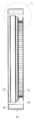
도 1은 본 발명의 제한 베어링의 개략적인 단면도,
도 2는 도 1의 감속 베어링의 개략적인 사시도,
도 3a 내지 3c는 본 발명의 감속 베어링의 내부 링의 개략도,
도 4a 내지 4c는 본 발명의 감속 베어링의 중앙 링의 개략도,
도 4d는 추가적인 실시 예로서 본 발명의 감속 베어링의 중앙 링의 개략도,
도 5a 내지 5c는 본 발명의 감속 베어링의 외부 링의 개략도,
도 6a 내지 6c는 본 발명에 따른 감속 베어링의 감속 스테이지의 개략도,
도 7a 내지 7e는 본 발명에 따른 감속 베어링의 다른 실시 예의 개략도,
도 8a 내지 8d는 본 발명의 병렬 구성의 2 스테이지 감속 베어링의 개략도,
도 9a 내지 9d는 본 발명의 직렬 구성의 2 스테이지 감속 베어링의 개략도,
도 10a 및 10b는 본 발명에 따른 전기 모터의 개략도,
도 10c는 본 발명에 따른 전기 모터의 추가적인 실시 예의 개략도이다.The present invention is not limited to the general aspects of the present invention, but on the basis of exemplary embodiments, reference will now be made, by way of example only, to the accompanying drawings, in which: . In the drawing:
1 is a schematic cross-sectional view of a limiting bearing of the present invention,
Figure 2 is a schematic perspective view of the reduction bearing of Figure 1,
Figures 3a to 3c are schematic views of the inner ring of the reduction bearing of the present invention,
Figures 4a to 4c are schematic views of the center ring of the reduction bearing of the present invention,
Figure 4d is a schematic view of the center ring of the reduction bearing of the present invention as a further embodiment,
Figures 5a-5c are schematic views of the outer ring of the reduction bearing of the present invention,
Figures 6a to 6c are schematic views of a reduction stage of a reduction bearing according to the present invention,
Figures 7a to 7e are schematic views of another embodiment of a reduction gear according to the present invention,
8A to 8D are schematic views of a two-stage reduction bearing of the parallel arrangement of the present invention,
Figures 9a to 9d are schematic views of a two-stage reduction bearing of the tandem arrangement of the present invention,
10A and 10B are schematic diagrams of an electric motor according to the invention,
Figure 10c is a schematic diagram of a further embodiment of an electric motor according to the invention.
도면에서 동일하거나 유사한 형태의 부재들 또는 각각 대응하는 부품들에는, 그 항목을 다시 소개해야 하는 것을 방지하기 위해 동일한 참조부호들이 부여된다.In the drawings, like reference numerals are used to denote the same or similar elements or their corresponding parts in order to avoid having to re-introduce the same.
도 1에는 본 발명에 따른 감속 베어링(5)의 예시적인 실시 예의 단면이 개략적으로 도시된다. 감속 베어링(5)은 3개의 동심 링(concentric rings), 즉 내부 링(10), 중앙 링(20) 및 외부 링(30)을 구비한다. 좌측 부분에는 베어링 평면(41)이 표시되고, 베어링 평면(41)은 3개의 동심 링(10,20,30) 및 내부 링(10)과 중앙 링(20) 사이와 중앙 링(20)과 외부 링(30) 사이에 각각 위치되는 롤링 부재들(rolling elements)(50,51)의 2개의 동심 링의 일부분들을 포함한다. 따라서, 베어링 평면(41)에 있어서의 부재들은 3개의 회전가능한 링(10,20,30)을 가진 반경방향 롤링 베어링(radial rolling bearing)을 구성한다. 롤링 부재들(50,51)은 예시로서 실린더들(cylinders)이지만, 볼들(balls)과 니들들(needles) 등과 같이 베어링들에서 이용되는 임의의 다른 종류의 롤링 부재들이 이용될 수도 있다.Fig. 1 schematically shows a cross section of an exemplary embodiment of a
3개의 링들(10,20,30)은 링들(10,20,30)로부터 축방향으로 각각 연장되며 공통의 감속 스테이지 평면(reduction stage plane)(42)에 놓여 있는 연장부들(16,26,36)을 가진다. 이들은, 중앙 링 연장부(26) 내측의 반경방향으로 배향된 채널들(radically oriented channels) 내에 감금된 반경방향 가동 부재들(radically moving elements)(40)이 외주에 접촉되는 디스크-형상의 내부 링 연장부(16)와, 반경방향 가동 부재들(40)이 내주 표면에 접촉되는 외주 링 연장부(36)로 이루어진 감속 스테이지(reduction stage)(7)를 구성한다. 외부 링 연장부(36) 및 내부 링 연장부(16)의 원주 표면들(12)의 구조체는 도 3, 5 및 6과 관련하여 설명될 것이다.The three rings 10,20 and 30 extend axially from the
도 2에는 도 1에 따른 감속 베어링(5)의 개략적인 사사도가 도시된다. 베어링 부품의 롤링 부재들(50,51)이 롤링 부재 케이지들(rolling element cages)(52,53)에 감금되어 있는 것을 볼 수 있다. 감속 베어링(5)이 그의 전체 직경의 상당 부분을 구성하는 중심 개구(13)를 가진 것으로 도시된다. 추가로, 중앙 링(20)과 외부 링(30)에는 입력 및 출력 수단에 대한 연결 및 부착을 위한 3개의 홀(holes), 즉 지지 구조체에 대한 부착을 위한 외부 링(30)에 있어서의 관통 홀(through hole)(38), 중앙 링(20)에 있어서의 출력 연결부(28) 및 내부 링 연장부(16) 내의 입력 연결부(18)가 도시된다.Fig. 2 shows a schematic perspective view of the
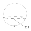
도 3a, 3b 및 3c에는 내부 링(10)의 상세도가 도시된다. 도 3a에는 원형 베어링 레이스(11)로서 구성된 베어링 부품 및 대형 중심 개구(13)를 가진 내부 링(10)의 사시도가 도시된다. 이러한 베어링 레이스(bearing race)(11)는 도 1 및 2에 도시된 롤링 부재들(50)의 내측 서클(inner circle)을 지지한다. 축방향으로, 비원형 외주 표면(12)을 가진 디스크-형상의 내부 링 연장부(16)가 도시된다. 도 3a에 도시된 바와 같이, 참조 부호 16에 인접한 부분은 최소 직경을 가진 밸리부(valley)(15)로서 구성되는 반면, 그 부분의 위와 아래에서는, 원주 표면(12)이 2개의 얕은 피크부(peak)(14)를 보여주고, 전체 원주 표면(12)은 타원형으로 된다. 밸리부(15)의 반대측에는 다른 밸리부가 위치된다. 표면(12)은 3개 이상의 피크부를 가질 수도 있다.Figures 3a, 3b and 3c show a detailed view of the
도 3b에는 내부 링(10)의 보다 상세한 단면도가 도시되고, 도 3c에는 도 3b의 부분 C의 확대도가 도시된다. 원주 표면(12)은 그의 경계들 위로 약간 상승된, 피크부(14)로 표시된 중심부를 가진다. 이 상승된 중심부는 2개의 피크부(14,14')들의 중간에 있는 밸리부(15)의 위치에서 사라질 것이다. 밸리부 위치에서의 표면은 도 3c에서 점선으로 표시된다. 이러한 높이의 변화는, 도 1 및 2에 도시된 선형 가동 부재들(40)이 중앙 링 연장부(26)에 있어서의 각 반경방향 채널들에서 반경방향 이동을 수행하게 한다.Figure 3b shows a more detailed cross-sectional view of the
도 4a, 4b, 4c에는 중앙 링(20)이 보다 상세하게 도식적으로 도시된다. 도 4a의 사시도에 도시된 바와 같이, 중앙 링(20)은 외측면상의 원형 베어링 레이스(21) 및 내측면 상의 원형 베어링 레이스(22)을 가진 베어링 부품으로 구성되고, 베어링 레이스들(21,22)은 도 1 및 2의 롤링 부재들(50,51)과 각각 접촉하고 있다.4a, 4b and 4c, the
축방향 중앙 링 연장부(26)는, 도 1 및 2에 도시된 반경방향 가동 부재들(40)의 선형 이동을 안내하는 반경방향 채널들(24)을 가진 케이지(cage)를 구비한다. 중앙 링 연장부(26) 그 자체는 원통 형상으로 이루어져 있다. 그의 내경은 피크부(14,14') 직경까지의 내부 링 연장부(16)의 외경보다 약간 더 크다.The axial
도 4d에는, 중앙 링 연장부(26)가 추가 연장되고, 그루브(groove)들일 수도 있는 추가적인 반경방향 채널들(124)이 추가된 것이 도시된다. 이러한 실시 예로 인해, 감속 베어링의 운반 기능(carrying capacity)이 증대된다. 반경방향 채널들(24,124)은 2열로 배열된다.In Figure 4d, the
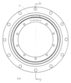
도 5a, 5b, 5c에는, 도 1 및 2의 본 발명의 감속 베어링(5)의 외부 링(30)의 개략도가 도시된다. 외부 링(30)은 도 1 및 2에 도시된 롤링 부재들 중 외부 링의 롤링 부재들(51)과 접촉하는 베어링 레이스(31)로서 구성되는 내주 베어링 표면을 가진다. 축 방향에 있어서, 외부 링 연장부(36)는 베어링 레이스(31)의 직경보다 작은 직경을 갖는 내주 표면을 가지며, 내부 링 연장부(16)의 피크부들의 피크부(14,14') 높이와 밸리부(15) 높이 간의 차이에 대략 부합하는 깊이를 갖는 그루브들(32)을 가진다. 그루브들(32)의 반경방향 높이의 변화는 내부 링 연장부(10)의 원주 표면(12)의 변화를 따르며 감속 스테이지의 감속비만큼 원주 방향으로 짧아진다.Figures 5a, 5b and 5c show schematic views of the
그루브들(32)의 개수는 중앙 링 연장부(26)에 있어서의 반경방향 채널들(24)의 개수와 약간 차이가 있는데, 특히 2개의 피크부의 경우, 통상 2만큼 차이가 있다. The number of the
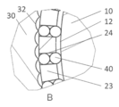
도 6a, 6b 및 6c에는, 감속 스테이지 평면(42)의 단면에서, 내부 링(10), 중앙 링(20) 및 외부 링(30)을 가진 본 발명에 따른 단일-스테이지 감속 베어링(5)의 추가적인 예시적 실시 예가 도시된다. 세퍼레이터(separator)(23)로서 구축된 중앙 링 연장부(26)는 원형 형상으로 이루어져 있다. 내부 링 연장부(16)의 외주 표면(12)은, 도 6a의 좌측 위치와 우측 위치에서는 세퍼레이터(23)의 내부 표면에 대해 좁은 간극(narrow gap)을 남기면서, 정상 위치와 바닥 위치에서의 세퍼레이터(23)의 내경에 매칭된다. 이는, 외부 링 세퍼레이터(16)의 외주 표면(12)이 원형이 아니라 상부 위치와 바닥 위치에서 2개의 피크부를 보여줌을 시사한다. 이와 대조적으로 외부 링 연장부(36)의 내주 표면에는, 세퍼레이터(23)의 반경방향 채널들(24) 내측에 위치된 반경방향 가동 부재들(40)보다 약간 넓은 다수의 그루브(32)들이 나타난다.Figures 6a, 6b and 6c show an embodiment of a single-
감속 베어링의 최소 직경을 유지하는 것과 관련하여, 감속 베어링의 운반 기능을 증가시키기 위해, 보다 많은 롤링 부재들(40)이 2 이상의 열로 반경방향 그루브들(24)을 가진 케이지에 위치될 수 있다. 예컨대, 도 6b를 참조하라.With respect to maintaining the minimum diameter of the reduction bearing, more
감속 베어링의 운반 기능을 추가 강화시키기 위해, 세퍼레이터에 있어서의 모든 제2 그루브(every second groove)가 생략될 수 있고, 이에 의해 감속비가 유지되면서 세퍼레이터들(23)의 벽 두께가 확장된다. 세퍼레이터들(23)의 확장된 벽을 통해, 개구들(29)이 중앙 링(20)에 통해 축방향으로 안내될 수 있다. 예컨대, 스크류가 안내된 개구(29)에 체결될 수 있다.In order to further enhance the transport function of the reduction bearing, every second groove in the separator may be omitted, thereby enlarging the wall thickness of the
도 4d에서 알 수 있는 바와 같이, 감속 베어링의 운반 기능의 추가적인 강화는, 중앙 링 연장부(26)의 연장 및 반경방향으로 하나의 톱니만큼 시프트되는 롤링 부재들과 추가적인 그루브들(124)의 추가에 의해 달성될 수 있다.As can be seen in Figure 4d, further reinforcement of the bearing function of the reduction bearing is achieved by the addition of rolling elements and
내부 링(10)을 회전시킴으로서 세퍼레이터(23)에 있어서의 반경방향 가동 부재들(40)이 집합적인 회전 파형 운동(collective revolving wave type motion)을 하게 된다. 그루브들의 개수가 반경방향 채널들(24)의 개수보다 2만큼 더 많기 때문에, 본 발명의 감속 베어링(5)의 입력으로서의 내부 링(10)의 회전으로 인해 반경방향 가동 부재들(50)은 피크부(14,14') 통과시 그루브들(32)의 편심(off-center)으로부터 중심(center)으로 외부 링 연장부(36)의 각 그루브들(32) 안으로 밀려나게 되고, 이의 의해 내부 링 연장부(16)의 외주 표면(12) 상의 피크부(14,14')를 각자가 통과하면서, 즉 내부 링(10)의 반회전(half revolution)마다 중앙 링(20)과 외부 링(30)이 하나의 그루브(32)의 량만큼 서로 상대적으로 회전하게 된다.By rotating the
도 6b 및 6c에는 도 6a의 F 및 G, 즉 피크부(14) 높이 및 밸리부(15) 높이에서의 확대 발췌도가 각각 도시된다. 도 6b에 도시된 바와 같이, 피크부(14) 높이에서, 중앙에 도시된 반경방향 가동 부재들(40)은 대향하는 그루브들(32) 내로 최대한 밀려나 있다. 도 6c에 도시된 바와 같이, 밸리부(15) 높이에서, 선형 가동 부재들(40)은 2개의 이웃한 그루브들(32) 사이의 에지(edge)에 의해 대향하게 된다. 내부 링(10)의 추가 회전으로 인해, 내부 링(10)의 회전 방향에 따라 세퍼레이터(23)는 시계방향 또는 반시계방향으로 조금 회전하게 될 것이고, 이에 따라 내부 링 연장부(16)의 외주 표면(12)상의 다음 피크부(next peak)(14)의 도착과 함께, 선형 가동 부재들(40)은 다음 이웃한 그루브(32) 내로 밀려나게 될 것이다.Figures 6b and 6c show enlarged excerpts at F and G of Figure 6a, the height of the
도 1에서 알 수 있는 바와 같이, 매우 컴팩트한 설계가 달성되며, 이와 동시에 감속 작용 및 반경방향 베어링 기능이 동시에 보장된다.As can be seen in Figure 1, a very compact design is achieved, while at the same time the deceleration and radial bearing functions are ensured at the same time.
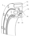
도 7a 내지 7e에는 본 발명에 따른 감속 베어링(5)의 추가적인 실시 예가 도시된다. 도 7a의 반개 사시도(half-open perspective)에 도시된 감속 베어링(5)의 구조는, 반경방향 가요성 롤러 베어링(60)이 반경방향 가동 부재들(40)을 가진 세퍼레이터(23) 및 내부 링 연장부(16)의 외주 표면(12) 사이에 개재되어 있다는 것을 제외하고, 도 1 및 2에 도시된 것과 거의 동일하다. 도 7e에서 가장 잘 알 수 있는 바와 같이, 반경방향 가요성 롤러 베어링(60)은 내부 베어링 레이스(62) 및 외부 링 베어링 레이스(63) 사이에 위치된 롤링 부재들(61)을 구비한다. 도 7b, 7c 및 7d에는 추가적인 상세 단면도 및 사시도가 도시된다. 반경방향 가요성 롤러 베어링(60)을 이용함으로써 마찰을 감소시키고 감속 베어링(5)의 수명 및 효율을 증대시킨다. 반경방향 가요성 롤러 베어링(60) 그 자체는 큰 반경방향 힘들을 지탱할 필요가 없으며, 그 힘들은 베어링 평면(41)에 있어서의 롤링 부재들(50,51)에 의해 흡수된다.7a to 7e show a further embodiment of a
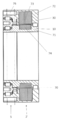
도 8a 내지 8d에는 서로 내측에 동심으로 배열되는 2개의 감속 스테이지(107,108)를 가진 본 발명의 감속 베어링(105)의 추가적인 예시적 실시 예가 도시된다. 도 8a에 도시된 제1 감속 스테이지(107)는 내부 링(10), 중앙 링(107) 및 외부 링(30)을 구비한다. 제2 감속 스테이지(109)는 내부 링(110), 중앙 링(120) 및 외부 링(130)을 구비한다. 제1 감속 스테이지(107)의 외부 링(30)은 제2 감속 스테이지(109)의 내부 링(110)과 동일하다. 다시 말해, 도 8에 도시된 동심의 2-스테이지 병렬 구성의 중간 링(30/110)은 베어링 평면에서 2개의 베어링 레이스, 즉 외측면상에 하나 그리고 내측면상에 하나를 가진다. 따라서, 도 8의 병렬 구성의 2-스테이지 감속 베어링(105)은 베어링 평면에 있어서 롤링 부재들(50,51)의 4개의 동심 서클(circles)을 가진다. 8A to 8D show a further exemplary embodiment of a
5개의 링(10,20,30/110,120,130)의 각각은 그 자체의 축방향 연장부들을 가지고, 그 연장부들은 원칙적으로 이전 도면들에 도시된 것들과 같은 방식으로 구성된다.Each of the five rings 10, 20, 30/110, 120, and 130 has its own axial extensions, the extensions of which are in principle constructed in the same manner as shown in the previous figures.
도 8b는 감속 베어링(105) 내부의 다른 부품들을 보여주기 위해 3개의 영역을 개구한 도면으로, 일측으로부터는 2-스테이지 감속 베어링(105)를 도시한다. 상부 우측의 개구된 영역에는, 롤링 부재들(50,51,50',51') 및 링들(10,20,30/110,120,130)이 감속 베어링(105)의 반경방향 베어링 기능을 구성하는 베어링 평면(41)이 도시된다.Fig. 8B shows three areas open to show other parts inside the
도 8d에는 영역 A를 가진 최하위 개구가 확대 도시된다. 최내곽의 제1 스테이지(107)는 예컨대 도 6의 단일 스테이지 실시 예와 같은 방식으로 구성됨을 명확히 알 수 있을 것이다. 도 8c에는 영역 B의 확대도가 도시된다. 도 8c 및 8d는 도 6b 및 6c의 도면들과 각각 대응한다.In Fig. 8D, the lowermost aperture having the area A is enlarged. It will be appreciated that the innermost
영역 B를 포함하는 내부도에서, 제2 감속 스테이지(109)의 감속 스테이지 평면(42) 내측이 일별(glimpse)될 수 있데, 제2 감속 스테이지(109)에 있어서의 반경방향 가동 부재들(40)은 예컨대 도 8b의 영역 B에 도시된 제1 스테이지(107)의 반경방향 가동 부재들보다 더 큰 것으로 도시된다. 제2 감속 스테이지(109)의 작용 원리는 제1 감속 스테이지의 작용 원리와 동일하다.The inside of the
이러한 병렬 동심 구성에 의해, 제1 감속 스테이지(107)의 감속 비율(reduction factor)과 제2 감속 스테이지(109)의 감속 비율의 승산으로 산출되는 매우 큰 감속 비율을 가진 감속 작용에 2개의 감속 스테이지를 조합하는 것이 가능하게 된다. 이에 따라 10,000 이상의 감속 지수가 달성될 수 있다.With such a parallel concentric configuration, two
본 발명의 감속 베어링(5,105)의 베어링 평면(41)에 있어서의 베어링 부품들에서 반경방향 힘들이 유지되기 때문에, 감속 스테이지 평면(42)에 있어서의 구조체들에 포함된 감속 작용은 반경방향 힘들을 크게 받지 않으며, 이에 따라 반경방향 힘들로 인한 차단(blocking)이 효과적으로 제거된다.Since the radial forces are held in the bearing parts in the bearing
도 9a 내지 9d에는 본 발명의 감속 베어링(205)의 추가적인 예시적 실시 예가 도시된다. 감속 베어링(205)은 직렬 구성의 2-스테이지이며, 즉 2개의 스테이지(207,209)는 감속 베어링(205)의 중심축(6)을 따라 축방향으로 정렬되고, 감속 베어링은, 도 9b에 도시된 바와 같이, 다시 기본적으로 원형 형상을 가진다. 2개의 감속 스테이지(207,209) 각각은, 이전 도면들에 도시된 바와 같이 주로 구성된 3개의 동심 링(10,20,30 및 210,220,230)을 각각 구비한다.9A-9D illustrate a further exemplary embodiment of the reduction bearing 205 of the present invention. The
도 9에 도시된 구성에서, 제1 감속 스테이지(207)의 내부 링(10)은 입력 연결부(18)에 의해 구동된다. 외부 링(30)은 관통 홀(38)에 의해 지지 구조체(미도시)에 부착될 수 있다. 내부 링(10)의 회전은 제1 감속 스테이지(207)의 중앙 링(20)의 저속 회전을 초래할 것이다.In the configuration shown in Fig. 9, the
제1 감속 스테이지(207)의 중앙 링(20)은, 스플라인 연결부(spline connection)로서 구축된 구동 연결부(212)을 통해 제2 감속 스테이지(209)의 내부 링(210)에 연결된다. 도 9d의 확대도에 도시된 스플라인 연결부는 도 9c의 확대도에 도시된 원주 톱니(circumferential toothing)를 가진다.The
중앙 링(220)은 출력 연결부(225)를 가진다. 마찬가지로 외부 링(230)은 지지 구조체와의 연결을 위한 관통 홀(38)을 가진다. 따라서, 제1 감속 스테이지(207)의 내부 링(10)의 입력부(18)에서의 회전은 제2 감속 스테이지(209)의 중앙 링(220)에 있어서의 출력부(225)의 초저속 회전을 초래한다.The
감속 스테이지들(207,209)는, 감속 스테이지들이 원하는 감속비로 선택될 수 있으며 자유롭게 선택가능한 높은 감속비에 도달하도록 도 9에 도시된 방식으로 조합될 수 있도록, 모듈러 방식(modular manner)으로 구축될 수 있다.Deceleration stages 207 and 209 may be constructed in a modular manner so that the deceleration stages can be selected at a desired deceleration ratio and combined in the manner shown in Fig. 9 to reach a freely selectable high deceleration ratio.
도 8의 병렬 구성의 감속 베어링(105)의 경우에서와 같이, 2개의 감속 스테이지(207,209)의 회전 운동은 개별적으로 이용될 수 있고, 이와 함께 본 발명의 감속 베어링(205)의 융통성에 추가된다. 2개의 스테이지(207, 209)는, 원하는 구성에 따라, 도 9에 도시된 본 예시에서와 같이 동일한 방식으로 배향되거나, 서로 마주하는 베어링 평면들 또는 감속 평면들을 가질 수 있다.As in the case of the
도 10a 및 10b에는 본 발명에 따른 전기 모터(2,2')의 2개의 예시적인 실시 예가 개략적으로 도시된다.10a and 10b schematically show two exemplary embodiments of the
도 10a에 도시된 전기 모터(2)는, 로터 코일들(74)을 가진 로터(71) 주위에 배열되는 스테이터(71)를 하우징하는 케이싱(72)을 구비하고, 로터(71)는, 축방향으로 코일들(74)의 각 측면에 있는 모터 베어링들(70)에 의해 케이싱에 지지된다. 본 발명에 따른 감속 베어링(5)은 케이싱 연결부(76)를 통해 케이싱(72)에 부착된다. 로터(71)는 스플라인 연결부(75)에 의해 감속 베어링(5)의 내부 링(10)에 구동가능하게 연결된다. 중앙 링(20)은 로터(71)에 대해 감소된 속도로 회전하는 출력 연결부(28)를 가진다. 여기서, 감속 베어링(5)은 연결부들(75,76)에 의해 전기 모터(2)와 통합된다.The
도 10b에 도시된 전기 모터(2')의 대안적인 실시 예는, 감속 베어링(5)이 완전히 통합된다는 점에서 도 10a에 도시된 전기 모터와 다르다. 케이싱(72)은 외부 링(30)과 일체이고, 로터(71)는 감속 베어링(30)의 내부 링(10)과 일체이다. 다른 측면상의 반경 방향 힘들은, 감속 베어링, 특히 베어링 평면(41)에 배열된 베어링 부품들에 의해 생성되기 때문에, 단 하나의 모터 베어링(70)이 존재한다.An alternative embodiment of the electric motor 2 'shown in Fig. 10b differs from the electric motor shown in Fig. 10a in that the
도 10c에 도시된 전기 모터(2,2')의 추가적인 실시 예에서는, 보다 높은 통합이 수행된다. 얇은-갭 타입 전기 모터(thin-Gap type electric motor)(2,2')가 도 10c에 도시된다. 감속 베어링(5)은 완전 통합형이다. 케이싱(172)은 중앙 링(20)과 일체이다. 로터(171)는 감속 베어링(5)의 내부 링(10)과 일체이다. 스테이터(173)는 로터(171)에 대해 작은 갭(small gap)을 가진다. 따라서, 매우 소형으로 구축될 수 있는 전기 모터(2,2')가 이용될 수 있다.In a further embodiment of the
2개의 예시적인 실시 예는 전기 모터(2,2')의 매우 효율적이고 컴팩트한 설계를 구성하는데, 이들은 컴팩트한 감속 전기 모터 작용을 필요로 하는 로봇공학 및 다른 기술 분야에서 매우 유용하다. The two exemplary embodiments constitute a very efficient and compact design of the
개별적인 특징들 및 도면들로부터 취해진 것들을 포함하고 다른 특징들과의 조합으로 개시된 모든 명명된 특징들은 단독으로 또는 조합으로 본 발명에 중요한 것을 간주된다. 본 발명에 따른 실시 예들은 개별적인 특징들이나 여러 특징들의 조합을 통해 실시될 수 있다. "특히" 또는 "특별히"라는 표현과 함께 조합된 특징점들은 바람직한 실시 예로서 취급된다.All the named features disclosed in combination with other features, including those taken from the individual features and drawings, are considered to be significant to the present invention, alone or in combination. The embodiments according to the present invention can be implemented by individual features or a combination of features. Feature points combined with the expressions "specifically" or "specifically" are treated as preferred embodiments.
2, 2', 2'': 전기 모터
5: 감속 베어링
6: 중심 축
7: 감속 스테이지
10: 내부 링
11: 베어링 레이스
12: 원주 표면
13: 중심 개구
14, 14': 피크부
15: 밸리부
16: 내부 링 연장부
18: 입력 연결부
20: 중앙 링
21: 베어링 레이스
22: 베어링 레이스
23: 세퍼레이터
24: 반경방향 채널들
26: 중앙 링 연장부
28: 출력 연결부
29: 개구
30: 외부 링
31: 베어링 레이스
32: 그루브들
36: 외부 링 연장부
38: 관통 홀
40, 40': 반경방향 가동 부재들
41: 베어링 평면
42: 감속 스테이지 평면
50, 50': 롤링 부재들
51, 51': 롤링 부재들
52, 53: 롤링 부재 케이지
60: 반경방향 가요성 롤러 베어링
61: 롤링 부재들
62: 내부 베어링 레이스
63: 외부 베어링 레이스
70: 모터 베어링들
71: 로터
72: 케이싱
73: 스테이터
74: 로터 코일들
75: 스플라인 연결부
76: 케이싱 연결부
105: 감속 베어링
107: 제1 감속 스테이지
109: 제2 감속 스테이지
110: 내부 링
120: 중앙 링
123: 세퍼레이터
124: 추가적인 반경방향 채널
130: 외부 링
171: 로터
172: 케이싱
173: 스테이터
205: 감속 베어링
207: 제1 감속 스테이지
209: 제2 감속 스테이지
210: 내부 링
212: 구동 연결부
220: 중앙 링
225: 출력 연결부
230: 외부 링2, 2 ', 2'': electric motor
5: Deceleration bearing
6: center axis
7: Deceleration stage
10: Inner ring
11: Bearing race
12: circumferential surface
13: center opening
14, 14 ': peak portion
15:
16: Inner ring extension
18: Input connection
20: center ring
21: Bearing race
22: Bearing race
23: Separator
24: Radial channels
26: center ring extension
28: Output connection
29: aperture
30: outer ring
31: Bearing race
32: Grooves
36: outer ring extension
38: Through hole
40, 40 ': radial moving members
41: Bearing plane
42: Deceleration stage plane
50, 50 ': rolling members
51, 51 ': rolling members
52, 53: rolling member cage
60: Radial flexible roller bearing
61: rolling members
62: Inner bearing race
63: Outer bearing race
70: Motor bearings
71: Rotor
72: casing
73:
74: Rotor coils
75: spline connection
76: casing connection part
105: Reduction bearing
107: first deceleration stage
109: second deceleration stage
110: Inner ring
120: center ring
123: Separator
124: Additional radial channels
130: outer ring
171: Rotor
172: casing
173:
205: Reduction bearing
207: first deceleration stage
209: second deceleration stage
210: inner ring
212:
220: center ring
225: Output connection
230: outer ring
Claims (15)
상기 적어도 3개의 동심 링(10,20,30;110,120,130;210,220,230)은 내부 링(10,110,210), 중앙 링(20,120,220) 및 외부 링(30,130,230)을 포함하고,
상기 내부 링(10,110,210)과 상기 중앙 링(20,120,220)은 롤링 부재들(50,51;50',51')의 상기 적어도 2개의 동심 링의 내측을 위한 베어링 레이스들(11,22)로서 구성되고,
상기 중앙 링(20,120,220)과 상기 외부 링(30,130,230)은 롤링 부재들(50,51;50',51')의 상기 적어도 2개의 동심 링의 외측을 위한 베어링 레이스들(21,31)로서 구성되고,
상기 감속 베어링(5,105,205)은 적어도 하나의 감속 스테이지(7;107,109;207,209)를 가지고,
상기 내부 링(10,110,210), 상기 중앙 링(20,120,220) 및 상기 외부 링(30,130,230)은 각각, 상기 감속 베어링(5,105,205)의 축방향으로 연장되며 공통의 감속 스테이지 평면(42)에 놓여있는 내부 링 연장부(16), 중앙 링 연장부(26) 및 외부 링 연장부(36)를 가지고,
상기 중앙 링 연장부(26)는 상기 내부 링 연장부(16)와 상기 외부 링 연장부(36) 간에 파형 감속 작용(wave-type reduction action)을 전달하도록 구성되는
감속 베어링.
A reduction bearing (5,105,205) having at least two concentric rings of at least three concentric rings (10,20,30; 110,120,130; 210,220,230) and rolling elements (50,51; 50 ', 51'
The at least three concentric rings (10, 20, 30; 110, 120, 130; 210, 220, 230) include inner rings (10, 110, 210), center rings (20, 120, 220) and outer rings
Wherein the inner ring (10,110,210) and the center ring (20,120,220) are configured as bearing races (11,22) for the inside of the at least two concentric rings of rolling elements (50,51; 50 ', 51' ,
The center ring (20,120,220) and the outer ring (30,130,230) are configured as bearing races (21,31) for the outside of the at least two concentric rings of rolling elements (50,51; 50 ', 51' ,
Wherein the reduction bearing (5,105,205) has at least one reduction stage (7; 107,109; 207,209)
Wherein the inner ring (10,110,210), the center ring (20,120,220) and the outer ring (30,130,230) each have an inner ring extension (5,105,205) extending in the axial direction of the reduction bearing (16), a center ring extension (26) and an outer ring extension (36)
The center ring extension 26 is configured to transfer a wave-type reduction action between the inner ring extension 16 and the outer ring extension 36
Deceleration bearings.
상기 내부 링 연장부(16)는 중심 개구(13)를 갖거나 갖지 않는 디스크 형상이며 하나 이상의 피크부(14,14')를 가진 외주 표면(12)을 구비하고, 상기 외부 링 연장부(36)는 그루브들(32)을 가진 내주 표면을 구비하거나,
상기 내부 링 연장부(16)는 중심 개구(13)를 갖거나 갖지 않는 디스크 형상이고 그루브들(32)을 가진 외주 표면을 구비하고, 상기 외부 링 연장부(36)는 하나 이상의 피크부(14,14')를 가진 내주 표면을 구비하는 것을 특징으로 하는
감속 베어링.
The method according to claim 1,
The inner ring extension 16 is disc shaped and has a central aperture 13 and has an outer peripheral surface 12 having at least one peak 14,14 ' May have an inner peripheral surface having grooves 32,
The inner ring extension 16 has a disc-shaped outer surface with grooves 32 with or without a central aperture 13 and the outer ring extension 36 has at least one peak 14 , 14 ')< / RTI >
Deceleration bearings.
중앙 링 연장부(26)는 상기 외부 링 연장부(36)의 내부 표면 및 상기 내부 링 연장부(16)의 외주 표면(12)과 접촉하는 반경방향 가동 부재들(40,40')을 수용하는 반경방향 채널들(24,124)을 정의하는 구조체들을 구비하고,
특히, 상기 반경방향 채널들(24,124)은 상기 공통의 감속 스테이지 평면(42)에 적어도 실질적으로 평행하게 배열되는 적어도 하나의 열에 위치되고,
특히, 상기 외부 링 연장부(36)의 내주 표면 또는 상기 내부 링 연장부(16)의 외주 표면에 있어서의 그루브들(32)의 개수는 상기 중앙 링 연장부(26)의 반경방향 채널들(24,124)의 개수보다 많거나 적고,
특히, 반경방향 채널들(24,124)을 정의하는 상기 중앙 링(20,120)의 상기 구조체들은 상기 중앙 링(20,120,220)과 일체로 되거나 교체 가능한 것을 특징으로 하는
감속 베어링.
3. The method according to claim 1 or 2,
The central ring extension 26 receives the radially movable members 40, 40 'that contact the inner surface of the outer ring extension 36 and the outer peripheral surface 12 of the inner ring extension 16 And defining radial channels (24,124)
In particular, the radial channels 24,124 are located in at least one row arranged at least substantially parallel to the common deceleration stage plane 42,
In particular, the number of grooves 32 on the inner circumferential surface of the outer ring extension 36 or on the outer circumferential surface of the inner ring extension 16 is greater than the number of grooves 32 in the radial channels 24,124), < / RTI >
In particular, the structures of the central ring (20,120) defining the radial channels (24,124) are characterized by being integral or interchangeable with the central ring (20,120,220)
Deceleration bearings.
특히, 상기 외부 링 연장부(36)의 상기 내주 표면에 있어서 상기 그루브들(32)의 반경방향 깊이는 특히, 상기 내부 링 연장부(16)의 상기 외주표면(12) 상의 상기 피크부 또는 피크부들(14,14')의 반경방향으로의 높이와 같거나 이를 초과하고,
특히, 상기 내부 링 연장부(16)의 상기 외주 표면(12) 상의 상기 피크부들(14,14')의 형상은 특히 상기 외부 링 연장부(16) 상의 그루브들(32)의 형상과 반대인 것을 특징으로 하는
감속 베어링.
4. The method according to any one of claims 1 to 3,
In particular, on the inner circumferential surface of the outer ring extension 36, the radial depth of the grooves 32 is greater than the radial depth of the outer circumferential surface 12 of the inner ring extension 16, Is equal to or greater than the height in the radial direction of the portions 14, 14 '
In particular, the shape of the peaks 14,14 'on the outer circumferential surface 12 of the inner ring extension 16 is particularly favorable with respect to the shape of the grooves 32 on the outer ring extension 16, Characterized by
Deceleration bearings.
상기 반경방향 가동 부재들(40,40')은 특히 니들들, 볼들 또는 실린더들과 같은 슬라이딩 또는 롤링 부재들(40,40')의 하나 이상의 열을 구비하는 것을 특징으로 하는
감속 베어링.
5. The method according to any one of claims 1 to 4,
Characterized in that said radially movable members (40, 40 ') comprise at least one row of sliding or rolling elements (40, 40'), in particular such as needles, balls or cylinders
Deceleration bearings.
반경방향 가요성 롤러 베어링(60)은 상기 중앙 링 연장부(26)와 상기 내부 링 연장부(16)의 상기 외주 표면(12) 사이에 개재되어 있는 것을 특징으로 하는
감속 베어링.
6. The method according to any one of claims 1 to 5,
Characterized in that a radially flexible roller bearing (60) is interposed between said central ring extension (26) and said outer peripheral surface (12) of said inner ring extension (16)
Deceleration bearings.
상기 적어도 3개의 동심 링(10,20,30;110,120,130;210,220,230) 및 상기 롤링 부재들(50,51';50',51')의 적어도 2개의 동심 링은 베어링 평면(41)에 배열되는 것을 특징으로 하는
감속 베어링.
7. The method according to any one of claims 1 to 6,
At least two concentric rings of the at least three concentric rings (10,20,30; 110,120,130; 210,220,230) and the rolling elements (50,51 ';50', 51 ') are arranged in the bearing plane Featured
Deceleration bearings.
상기 외부 링 연장부(36)의 내주 표면 상에 또는 상기 내부 링 연장부(16)의 외주 표면 상에 적어도 3개인 홀수 개의 피크부(14,14') 또는 짝수 개의 피크부(14,14')가 구비되는 것을 특징으로 하는
감속 베어링.
8. The method according to any one of claims 1 to 7,
An odd number of peak portions (14, 14 ') or even numbered peak portions (14, 14') of at least three on the inner peripheral surface of the outer ring extension (36) or on the outer peripheral surface of the inner ring extension ) Is provided
Deceleration bearings.
상기 내부 링(10,110,210) 및/또는 상기 중앙 링(20,120,220) 및/또는 상기 외부 링(30,130,230)은 외부 지지 구조체에의 부착을 위한 관통 홀들을 가진 것을 특징으로 하는
감속 베어링.
9. The method according to any one of claims 1 to 8,
Characterized in that the inner ring (10,110,210) and / or the center ring (20,120,220) and / or the outer ring (30,130,230) have through holes for attachment to an external support structure
Deceleration bearings.
상기 감속 베어링(5,105,205)은, 상기 외부 링(30,130,230)의 외경의 특히 35% 초과, 특히 50% 또는 60% 또는 70% 초과이고 90% 이하의 직경을 가진 축방향 중심 개구(13)를 가진 것을 특징으로 하는
감속 베어링.
10. The method according to any one of claims 1 to 9,
Characterized in that the reduction bearing (5,105,205) has an axial central opening (13) with a diameter of more than 35%, in particular 50% or 60% or more than 70% of the outer diameter of the outer ring (30,130,230) Featured
Deceleration bearings.
상기 감속 베어링(105,205)은, 적어도 하나의 제1 감속 스테이지(107,207)가 적어도 하나의 제2 감속 스테이지(109,209)에 구동가능하게 연결되도록 구성된 2이상의 감속 스테이지들(107,207;109,209)를 가지고,
상기 감속 스테이지들(107,207;109,209)은 서로 축방향으로 정렬되거나/정렬되고 서로에 대해 동심으로 배치되고,
특히, 제1 감속 스테이지(207)와 제2 감속 스테이지(209)는 축방향으로 정렬되고,
상기 제1 감속 스테이지(207)의 상기 내부 링(10), 상기 중앙 링(20) 및 상기 외부 링(30) 중 하나는 특히, 스플라인 연결부에 의해 상기 제2 감속 스테이지(209)의 상기 내부 링(210), 상기 중앙 링(220) 및 상기 외부 링(230) 중 하나와 연결되는 것을 특징으로 하는
감속 베어링.
11. The method according to any one of claims 1 to 10,
The reduction bearing (105,205) has two or more reduction stages (107,207; 109,209) configured such that at least one first reduction stage (107,207) is operatively connected to at least one second reduction stage (109,209)
The deceleration stages (107, 207; 109, 209) are axially aligned / aligned with each other and concentrically disposed with respect to each other,
In particular, the first reduction stage 207 and the second reduction stage 209 are aligned in the axial direction,
One of the inner ring (10), the center ring (20) and the outer ring (30) of the first reduction stage (207) is in particular fastened by the spline connection to the inner ring (210), the center ring (220) and the outer ring (230).
Deceleration bearings.
제1 감속 스테이지(107) 및 제2 감속 스테이지(109)는 서로 동심으로 배치되고,
상기 제2 감속 스테이지(109)는 상기 제1 감속 스테이지(107)를 중심으로 동심으로 배열되고,
상기 제1 감속 스테이지(107)의 외부 링(30)은 상기 제2 감속 스테이지(109)의 내부 링(110)과 일체인 것을 특징으로 하는
감속 베어링.
12. The method of claim 11,
The first deceleration stage 107 and the second deceleration stage 109 are disposed concentrically with each other,
The second deceleration stage 109 is concentrically arranged around the first deceleration stage 107,
The outer ring 30 of the first reduction stage 107 is integral with the inner ring 110 of the second reduction stage 109
Deceleration bearings.
상기 제1 감속 스테이지(107)의 상기 내부 링(10)과 상기 중앙 링(20) 중 하나 및 상기 제2 감속 스테이지(109)의 상기 중앙 링(120)과 상기 외부 링(130) 중 하나는 지지 구조체에 부착되거나 부착가능한 것을 특징으로 하는
감속 베어링.
13. The method of claim 12,
One of the inner ring 10 and the center ring 20 of the first reduction stage 107 and one of the center ring 120 and the outer ring 130 of the second reduction stage 109 Characterized in that it is attached or attachable to a support structure
Deceleration bearings.
상기 감속 베어링(105)은 상이한 스테이지들(107,109)에서 및 상이한 감속값들의 2개의 출력부들을 갖는 것을 특징으로 하는
감속 베어링.
14. The method according to any one of claims 10 to 13,
Characterized in that the reduction bearing (105) has two outputs at different stages (107, 109) and at different deceleration values
Deceleration bearings.
제 1 항 내지 제 14 항 중 한 항에 따른 적어도 하나의 감속 베어링(5,105,205)은 상기 전기 모터(2,2')와 또는 그 내부에 통합되고
상기 전기 모터(2,2')의 케이싱(72)은 상기 감속 베어링(5)을 위한 지지 구조체를 형성하고, 상기 전기 모터(2,2')의 로터(71)는 상기 감속 베어링(5)의 입력 링에 구동가능하게 연결되거나 그와 일체인 것을 특징으로 하는
감속 베어링.As the electric motor (2, 2 '),
A motor according to one of the claims 1 to 14, characterized in that at least one reduction bearing (5, 105, 205) is integrated with or within the electric motor
The casing 72 of the electric motor 2, 2 'forms a support structure for the reduction bearing 5, and the rotor 71 of the electric motor 2, 2' Characterized in that it is operatively connected to or integral with an input ring
Deceleration bearings.
Applications Claiming Priority (2)
| Application Number | Priority Date | Filing Date | Title |
|---|---|---|---|
| EP15182419.0A EP3135954A1 (en) | 2015-08-25 | 2015-08-25 | Reduction bearing and electric motor |
| EP15182419.0 | 2015-08-25 |
Publications (1)
| Publication Number | Publication Date |
|---|---|
| KR20170024513A true KR20170024513A (en) | 2017-03-07 |
Family
ID=54007618
Family Applications (2)
| Application Number | Title | Priority Date | Filing Date |
|---|---|---|---|
| KR1020150150120A KR20170024513A (en) | 2015-08-25 | 2015-10-28 | Reduction bearing and electric motor |
| KR1020160107507A KR20170024556A (en) | 2015-08-25 | 2016-08-24 | Reduction Bearing and Electric Motor |
Family Applications After (1)
| Application Number | Title | Priority Date | Filing Date |
|---|---|---|---|
| KR1020160107507A KR20170024556A (en) | 2015-08-25 | 2016-08-24 | Reduction Bearing and Electric Motor |
Country Status (7)
| Country | Link |
|---|---|
| US (1) | US20170063193A1 (en) |
| EP (2) | EP3135954A1 (en) |
| JP (2) | JP2017044329A (en) |
| KR (2) | KR20170024513A (en) |
| CN (2) | CN106481658A (en) |
| EA (1) | EA201691451A1 (en) |
| TW (2) | TW201708724A (en) |
Families Citing this family (14)
| Publication number | Priority date | Publication date | Assignee | Title |
|---|---|---|---|---|
| US10035261B2 (en) * | 2016-06-17 | 2018-07-31 | Schaeffler Technologies AG & Co. KG | Actuatable joint for a robotic system having an axial angular contact roller bearing |
| DE102017101565A1 (en) | 2017-01-26 | 2018-07-26 | Wittenstein Se | COAXIAL GEARBOX WITH POSITIVE TRANSLATION |
| WO2018176291A1 (en) | 2017-03-29 | 2018-10-04 | SZ DJI Technology Co., Ltd. | Hollow motor apparatuses and associated systems and methods |
| WO2018176292A1 (en) * | 2017-03-29 | 2018-10-04 | 深圳市大疆创新科技有限公司 | Driving device, operation method therefor, laser measurement device, and mobile platform |
| CN106907398B (en) * | 2017-05-02 | 2023-09-15 | 西安赛隆金属材料有限责任公司 | Bearing support device for high-speed rotating shaft |
| DE102018206065A1 (en) * | 2018-04-20 | 2019-10-24 | Aktiebolaget Skf | Roller bearing for supporting a radial deformation of the roller bearing and Rotatiionsanordnung with such a roller bearing |
| CN109340254B (en) * | 2018-12-14 | 2024-03-22 | 徐工集团凯宫重工南京股份有限公司 | Main driving bearing for shield machine |
| CN110529495A (en) * | 2019-08-30 | 2019-12-03 | 江苏如非轴承科技有限公司 | A kind of reinforced floating bearing structure of high revolving speed |
| DE102021004541A1 (en) | 2020-09-28 | 2022-03-31 | Sew-Eurodrive Gmbh & Co Kg | Drive, having a gear driven by an electric motor |
| CN112303114A (en) * | 2020-10-28 | 2021-02-02 | 上海电气风电集团股份有限公司 | Rolling bearing applied to wind driven generator and wind driven generator |
| EP4112955A1 (en) | 2021-06-29 | 2023-01-04 | Biatec Motion s.r.o. | Radiaxial bearing and electric motor |
| DE102023000624A1 (en) | 2022-03-15 | 2023-09-21 | Sew-Eurodrive Gmbh & Co Kg | Drive, comprising a gear driven by an electric motor |
| DE102023000623A1 (en) | 2022-03-15 | 2023-09-21 | Sew-Eurodrive Gmbh & Co Kg | Drive, comprising a gear driven by an electric motor |
| WO2023174656A1 (en) | 2022-03-15 | 2023-09-21 | Sew-Eurodrive Gmbh & Co. Kg | Drive comprising a transmission driven by an electric motor |
Family Cites Families (21)
| Publication number | Priority date | Publication date | Assignee | Title |
|---|---|---|---|---|
| US3468175A (en) * | 1967-08-15 | 1969-09-23 | Jan W Rabek | Transmission |
| JPS59170549A (en) * | 1983-03-18 | 1984-09-26 | Hitachi Ltd | Reduction gear |
| CN85200923U (en) * | 1985-04-01 | 1986-02-12 | 湖北省机械研究所 | Driving bearing |
| JPH02113048U (en) * | 1989-02-27 | 1990-09-10 | ||
| US6383110B1 (en) * | 1999-03-29 | 2002-05-07 | Synkinetics, Inc. | Nested modified-cam speed converter |
| US6416438B1 (en) * | 1999-04-30 | 2002-07-09 | ByongChol Choi | Transmitting unit |
| CN1381938A (en) * | 2001-04-18 | 2002-11-27 | 吴声震 | Speed-reducing cycloidal motor |
| JP4265748B2 (en) * | 2003-03-31 | 2009-05-20 | ナブテスコ株式会社 | Reducer using needle roller bearing |
| CN2653211Y (en) * | 2003-09-19 | 2004-11-03 | 徐建华 | High power speed reducing bearing |
| CN2758562Y (en) * | 2004-10-11 | 2006-02-15 | 孙连清 | Speed reducing transmission bearing |
| US8038562B2 (en) * | 2005-08-18 | 2011-10-18 | Ntn Corporation | Power transmission device |
| FR2897133B1 (en) * | 2006-02-06 | 2008-03-14 | Staubli Faverges Sca | METHOD FOR MANUFACTURING A REDUCER, REDUCER AND ROBOT INCORPORATING SUCH REDUCER |
| RU2329422C2 (en) * | 2006-05-18 | 2008-07-20 | Борис Георгиевич Хохряков | Transmission with transfer elements (versions) |
| CN201118347Y (en) * | 2007-11-16 | 2008-09-17 | 东莞市智通机电有限公司 | Electromotor deceleration motor with shift bearing |
| DE112011105253T5 (en) * | 2011-05-16 | 2014-02-13 | Harmonic Drive Systems Inc. | Unit type wave gear |
| DE112011105478T5 (en) * | 2011-07-29 | 2014-04-24 | Harmonic Drive Systems Inc. | Internally toothed gear unit with composite rolling bearing and wave gear |
| JP5767065B2 (en) * | 2011-09-22 | 2015-08-19 | Ntn株式会社 | Reduction gear |
| FR2997158B1 (en) * | 2012-10-22 | 2016-11-25 | Skf Ab | BEARING BEARING, IN PARTICULAR FOR PROPELLER OF SHIPS OR FOR WIND TURBINES |
| US9893356B2 (en) * | 2014-04-15 | 2018-02-13 | Panasonic Intellectual Property Management Co., Ltd. | Cathode active material for nonaqueous electrolyte secondary battery, nonaqueous electrolyte secondary battery, and method of producing cathode active material for nonaqueous electrolyte secondary battery |
| CN204458813U (en) * | 2014-12-05 | 2015-07-08 | 进发轴承有限公司 | Packaged reducer bearing |
| JP2016163978A (en) * | 2015-03-06 | 2016-09-08 | 大場 祥右 | Manufacturing method of resin branch pipe member and thermoplastic resin branch pipe member manufactured by manufacturing method |
-
2015
- 2015-08-25 EP EP15182419.0A patent/EP3135954A1/en not_active Withdrawn
- 2015-10-28 KR KR1020150150120A patent/KR20170024513A/en not_active Application Discontinuation
- 2015-10-29 JP JP2015213058A patent/JP2017044329A/en active Pending
- 2015-10-30 CN CN201510721003.9A patent/CN106481658A/en active Pending
- 2015-11-13 TW TW104137566A patent/TW201708724A/en unknown
-
2016
- 2016-08-08 EP EP16183253.0A patent/EP3135955A3/en not_active Withdrawn
- 2016-08-17 EA EA201691451A patent/EA201691451A1/en unknown
- 2016-08-24 JP JP2016163978A patent/JP2017096488A/en active Pending
- 2016-08-24 US US15/245,830 patent/US20170063193A1/en not_active Abandoned
- 2016-08-24 KR KR1020160107507A patent/KR20170024556A/en not_active Application Discontinuation
- 2016-08-24 TW TW105127109A patent/TW201713869A/en unknown
- 2016-08-25 CN CN201610721262.6A patent/CN106481659A/en active Pending
Also Published As
| Publication number | Publication date |
|---|---|
| EA201691451A1 (en) | 2017-05-31 |
| JP2017044329A (en) | 2017-03-02 |
| TW201713869A (en) | 2017-04-16 |
| TW201708724A (en) | 2017-03-01 |
| US20170063193A1 (en) | 2017-03-02 |
| CN106481659A (en) | 2017-03-08 |
| EP3135955A3 (en) | 2017-04-26 |
| CN106481658A (en) | 2017-03-08 |
| KR20170024556A (en) | 2017-03-07 |
| EP3135954A1 (en) | 2017-03-01 |
| EP3135955A2 (en) | 2017-03-01 |
| JP2017096488A (en) | 2017-06-01 |
Similar Documents
| Publication | Publication Date | Title |
|---|---|---|
| KR20170024513A (en) | Reduction bearing and electric motor | |
| RU2442046C2 (en) | Gear | |
| EP0388207B1 (en) | Transmission apparatus | |
| US20080030090A1 (en) | Magnetic power transmission system with RD motor | |
| KR101724659B1 (en) | Reverse cycloid reducer | |
| US8998763B2 (en) | Rotary speed-change transmission | |
| JP2020072641A (en) | Reduction gear and electrical facility | |
| JP2013015218A (en) | Transmission | |
| JP6262375B2 (en) | Speed change mechanism | |
| JP2014029203A (en) | Speed reducer of high change gear ratio using planetary gear mechanism | |
| KR20180099465A (en) | Reduction bearing and electric motor | |
| KR102436543B1 (en) | Cycloidal reducer | |
| WO2000063588A1 (en) | Reduction gearbox | |
| KR100235595B1 (en) | Transmission using bearing | |
| KR19990033596U (en) | Use deceleration machine for bearing | |
| KR100501562B1 (en) | A accelerating device used planetary gear unit | |
| KR102543898B1 (en) | Cycloid reducer with improved durability and performance by increasing rolling effect and distributing applied load by converting internal gear into plain bearing | |
| CN220687946U (en) | Cycloidal pin gear speed reducer with large reduction ratio | |
| CN211009753U (en) | Differential cycloidal gear speed change device | |
| CN211009754U (en) | Differential cycloid speed variator | |
| RU187959U1 (en) | ELECTROMECHANICAL DRIVE | |
| RU2523505C2 (en) | Disk planetary variator | |
| KR20150025165A (en) | Speed-reduction transmission bearing | |
| CN116972117A (en) | Cycloidal pin gear speed reducer with large speed reduction ratio and working method | |
| JP2016023793A (en) | Finite speed reducer |
Legal Events
| Date | Code | Title | Description |
|---|---|---|---|
| N231 | Notification of change of applicant | ||
| A201 | Request for examination | ||
| E902 | Notification of reason for refusal | ||
| E601 | Decision to refuse application |