KR20170023103A - Device and method for positioning a multi-aperture optical unit with multiple optical channels relative to an image sensor - Google Patents
Device and method for positioning a multi-aperture optical unit with multiple optical channels relative to an image sensor Download PDFInfo
- Publication number
- KR20170023103A KR20170023103A KR1020177001650A KR20177001650A KR20170023103A KR 20170023103 A KR20170023103 A KR 20170023103A KR 1020177001650 A KR1020177001650 A KR 1020177001650A KR 20177001650 A KR20177001650 A KR 20177001650A KR 20170023103 A KR20170023103 A KR 20170023103A
- Authority
- KR
- South Korea
- Prior art keywords
- optics
- image
- iris
- target
- axis
- Prior art date
Links
Images


Classifications
-
- G—PHYSICS
- G06—COMPUTING; CALCULATING OR COUNTING
- G06T—IMAGE DATA PROCESSING OR GENERATION, IN GENERAL
- G06T7/00—Image analysis
- G06T7/80—Analysis of captured images to determine intrinsic or extrinsic camera parameters, i.e. camera calibration
-
- H—ELECTRICITY
- H04—ELECTRIC COMMUNICATION TECHNIQUE
- H04N—PICTORIAL COMMUNICATION, e.g. TELEVISION
- H04N17/00—Diagnosis, testing or measuring for television systems or their details
- H04N17/002—Diagnosis, testing or measuring for television systems or their details for television cameras
-
- H—ELECTRICITY
- H04—ELECTRIC COMMUNICATION TECHNIQUE
- H04N—PICTORIAL COMMUNICATION, e.g. TELEVISION
- H04N23/00—Cameras or camera modules comprising electronic image sensors; Control thereof
- H04N23/50—Constructional details
- H04N23/54—Mounting of pick-up tubes, electronic image sensors, deviation or focusing coils
-
- H—ELECTRICITY
- H04—ELECTRIC COMMUNICATION TECHNIQUE
- H04N—PICTORIAL COMMUNICATION, e.g. TELEVISION
- H04N23/00—Cameras or camera modules comprising electronic image sensors; Control thereof
- H04N23/50—Constructional details
- H04N23/55—Optical parts specially adapted for electronic image sensors; Mounting thereof
-
- H04N5/2254—
-
- G—PHYSICS
- G06—COMPUTING; CALCULATING OR COUNTING
- G06T—IMAGE DATA PROCESSING OR GENERATION, IN GENERAL
- G06T2207/00—Indexing scheme for image analysis or image enhancement
- G06T2207/30—Subject of image; Context of image processing
- G06T2207/30204—Marker
Landscapes
- Engineering & Computer Science (AREA)
- Multimedia (AREA)
- Signal Processing (AREA)
- General Physics & Mathematics (AREA)
- Computer Vision & Pattern Recognition (AREA)
- Physics & Mathematics (AREA)
- Theoretical Computer Science (AREA)
- General Health & Medical Sciences (AREA)
- Biomedical Technology (AREA)
- Health & Medical Sciences (AREA)
- Length Measuring Devices By Optical Means (AREA)
- Studio Devices (AREA)
- Lens Barrels (AREA)
- Stereoscopic And Panoramic Photography (AREA)
- Camera Bodies And Camera Details Or Accessories (AREA)
- Cameras In General (AREA)
Abstract
이미지 센서와 관련하여 여러 개의 광 채널들을 포함하는 복수 조리개 광학기의 상대적 포지셔닝을 위한 디바이스는 기준 대상, 포지셔닝 디바이스 및 계산 디바이스를 포함한다. 기준 대상은 복수 조리개 광학기에 의해 기준 대상이 광 채널들 내의 채널당 하나의 이미지 영역으로 이미징되도록 배열된다. 포지셔닝 디바이스는 복수 조리개 광학기와 이미지 센서 사이의 상대적 위치를 변경하도록 제어 가능하다. 계산 디바이스는 기준 대상의 이미지들 내의 적어도 3개의 이미지 영역들에서 기준 대상의 실제 위치들을 결정하고 실제 위치들과 위치들의 비교에 기초하여 포지셔닝 디바이스를 제어하도록 구성된다.A device for relative positioning of a plurality of iris diverters comprising a plurality of optical channels in connection with an image sensor includes a reference object, a positioning device and a computing device. The reference object is arranged such that the reference object is imaged by the plurality of iris optics into one image area per channel in the optical channels. The positioning device is controllable to change the relative position between the plurality of iris optics and the image sensor. The computing device is configured to determine actual positions of the reference object in at least three image areas within the images of the reference object and to control the positioning device based on comparison of actual positions and positions.

Description
본 발명은 여러 개의 광 채널들을 포함하는 복수 조리개 광학기(multi-aperture optics)의 상대적 포지셔닝을 위한 디바이스 및 방법에 관한 것이다. 본 발명은 추가로, 복수 조리개 광학기를 디지털 이미지 센서와 능동적으로 정렬하기 위한 방법에 관한 것이다.The present invention relates to a device and method for relative positioning of multi-aperture optics comprising a plurality of optical channels. The present invention further relates to a method for actively aligning a plurality of iris diaphragm optics with a digital image sensor.
고해상도 소형 카메라 모듈들을 제조할 때, 대물렌즈(objective)를 집적하는 단계는 능동 정렬 프로세스를 수행하는 단계, 즉 발생하는 이미지를 관찰하고 평가하면서 이미지 센서에 대해 대물렌즈(object lens)를 능동적으로 정렬하는 단계를 포함한다. 이는 이미지 센서와 관련하여 대물렌즈를 이동시키고 발생하는 이미지를 이미지 선명도에 대한 사전 정의된 품질 기준들에 따라 평가(일반적으로 이미지의 서로 다른 위치들에서 이미지 콘트라스트 및/또는 모듈 전달 함수(module transfer function)[간단히: MTRF]를 측정)하는 것을 수반한다. 예를 들면, 측정된 품질 기준들을 최대화함으로써 포지셔닝이 최적화되고, 이미지 센서와 관련하여 이 위치에서 그에 따라 대물렌즈가 (예를 들면, 접착에 의해) 고정된다. 이를 위해 요구되는 하나의 전제 조건은 품질 기준들에 대해 의존하게 되는 대물렌즈의 특성들(예를 들면, 이미지 콘트라스트, MTF)이 예를 들어, US 2013/0047396 A1 또는 JP 20070269879로부터 공지된 바와 같이, 프로세스에서 사용된 위치의 시프트들에 대해 충분히 측정 가능한 정도로 변화할 것이라는 것이다.When manufacturing high-resolution miniature camera modules, the step of integrating the objective involves performing an active alignment process, i.e., actively aligning the object lens with respect to the image sensor while observing and evaluating the resulting image. . This involves moving the objective in relation to the image sensor and evaluating the resulting image in accordance with predefined quality criteria for image sharpness (generally image contrast and / or module transfer function at different locations of the image ) [Simply: MTRF]). For example, the positioning is optimized by maximizing the measured quality criteria, and the objective lens is thereby fixed at this position with respect to the image sensor (e. G., By gluing). One prerequisite for this is that the characteristics of the objective lens (e.g., image contrast, MTF) that are dependent on the quality criteria are determined, for example, as known from US 2013/0047396 A1 or JP 20070269879 , Will be sufficiently measurable for the shifts of the position used in the process.
능동 정렬에 관한 한, 대물렌즈들의 파라미터들이 포지셔닝 단계들과 관련하여 약간만 다르다면 종래의 최적화 알고리즘들은 실패할 것이다. 후자는 예를 들면, 큰 초점 깊이들을 갖는 대물렌즈들(그리고 특히, 마이크로렌즈 어레이들로 구성된 복수 조리개 대물렌즈들)에 적용되며, 여기서 대물렌즈와 이미지 센서 사이의 z 거리의 변화는 이미지 선명도에 단지 약간의 변화들만을 야기하는데, 이는 실제 경우들에는 측정하기가 어렵다.As far as the active alignment is concerned, conventional optimization algorithms will fail if the parameters of the objective lenses are only slightly different with respect to the positioning steps. The latter is applied, for example, to objective lenses with large focus depths (and, in particular, to multiple iris objectives consisting of microlens arrays), wherein the change in z-distance between the objective lens and the image sensor is dependent on the image sharpness It only causes a few changes, which is difficult to measure in real cases.
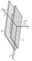
광학(z) 축에 관한 소형 카메라들의 종래의 대물렌즈들의 회전 대칭 레이아웃으로 인해, 대부분의 경우들에 산업용 자동 조립 기계들은 이미지 센서와 관련하여 광학기의 상대적 포지셔닝에 대해 5 자유도(그리고 이에 따라, 5개의 축들)를 나타낸다(예를 들어, 도 18에 도시된 바와 같이, x축, y축, z축을 따라 3x 평행이동 + x축 및 y축을 중심으로 한 2x 기울기 [tx, ty]). 따라서 설정된 능동 조립 프로세스들 및 기계들은 z축을 중심으로 한 어떠한 회전 대칭도 포함하지 않는 대물렌즈들을 정렬하기에 적합하지 않다. 이들은 예를 들어, 애너모픽(anamorphic) 대물렌즈들, 방향 선택적 필터 컴포넌트들을 포함하는 대물렌즈들뿐만 아니라, 마이크로렌즈 어레이들로 구성된 복수 조리개 대물렌즈들도 포함한다.Owing to the rotationally symmetrical layout of the conventional objectives of small cameras in relation to the optical (z) axis, in most cases, the industrial automatic assembly machines are able to obtain 5 degrees of freedom , 5 axes) (e.g., 3x translation along the x-, y-, and z-axes + 2x slope [tx, ty] about the x and y axes, as shown in FIG. 18). Thus, the active assembly processes and machines set are not suitable for aligning the objective lenses that do not include any rotational symmetry about the z-axis. These include, for example, as well as anamorphic objectives, objective lenses comprising directionally selective filter components, as well as multiple iris objectives consisting of microlens arrays.
도 18은 필요한 자유도 x, y, z(평행이동), tx, ty 및 tz (회전)의 표기로 이미지 센서 칩(16)을 형성하기 위한 복수 조리개 이미징 광학기(12)의 조립 레이아웃의 개략적인 이미지를 보여준다.Figure 18 shows an overview of the assembly layout of the multiple
설명된 두 제한들은 WO 2011/045324 A2로부터 공지된 바와 같이, 소위 전자 클러스터 눈과 같은 간단한 복수 조리개 이미징 대물렌즈들에 대해 결합하여 적용된다. 복수 조리개 배열은 x-y 평면에서 1차원 또는 2차원으로 확장되는 광 채널들의 어레이로 구성되며, 각 광 채널은 전체 객체 필드의 정해진 부분을 캡처한다.The two constraints described are applied in combination for simple multi-aperture imaging objectives such as so-called electron cluster eyes, as is known from WO 2011/045324 A2. The multiple iris arrangement consists of an array of optical channels that extend in one or two dimensions in the x-y plane, each optical channel capturing a predetermined portion of the entire object field.
(각각의 경우 x-y 평면에서 보았을 때) 연관된 하위 이미지의 중심에 대한 각각의 개별 광 채널의 조리개의 중심 위치의 위치는 여기서 재구성의 정확도 및/또는 전체 이미지의 해상도 성능 면에서 주요한 역할을 한다. 조리개의 중심 위치와 연관된 하위 이미지의 중심 위치 간의 차이(피치 차이)는 사용되는 이미지 센서의 1/2 픽셀 피치와 1 픽셀 피치 사이의 정밀도로 x, y의 평행이동 자유도를 따라 조정되어야 한다.The location of the center position of the iris of each individual optical channel relative to the center of the associated sub-image (as viewed in the x-y plane in each case) plays a major role here in the accuracy of the reconstruction and / or resolution performance of the entire image. The difference (pitch difference) between the center position of the iris and the center position of the sub-image associated with it must be adjusted along the x and y translation degrees of freedom between the half pixel pitch of the image sensor used and the one pixel pitch.
이러한 복수 조리개 광학기의 배열은 구체적으로, 소형 카메라 모듈들, 특히 (예를 들어, 스마트폰들, 태블릿들, 랩톱들 등과 같은 얇은 디바이스들에 사용되기 위한 목적으로) 초박형 구조 형태들을 갖는 것들을 실현하기 위해 개발되었다.The arrangement of such a plurality of diaphragm optics can be realized, in particular, in the form of miniature camera modules, especially those with ultra-thin structural features (for example for use in thin devices such as smart phones, tablets, laptops, etc.) .
이에 따라, 매우 작은 초점 길이들(예를 들면, f = 1.2㎜) 그리고 이에 따라 큰 초점 심도들을 갖는 마이크로렌즈들이 이용된다. 파장(W)의 회절 제한된 이미징을 갖는 이미지 공간(dz)에서의 초점 심도에 대한 공식 dz = 4* l*(Fl#)^2에 따라, 예를 들어, 550㎚인 파장의 광 그리고 F/# = 2.4인 f 번호에 대해 dz = 12.7㎛의 값이 달성된다.Thus, microlenses with very small focal lengths (e.g., f = 1.2 mm) and thus large focal depths are used. For example, according to the formula dz = 4 * l * (Fl #) 2 for the depth of focus in the image space dz with diffraction limited imaging of the wavelength W, A value of dz = 12.7 mu m is achieved for the f number of # = 2.4.
도 19는 이미지 센서(16)의 이미지 평면(BE)과 복수 조리개 광학기(12)의 정렬에 관한 요건들을 개략적으로 예시한다. 복수 조리개 광학기(12)는 1차원 또는 2차원 어레이로 배열되고 중심을 포함하는 여러 광 채널들을 포함한다. 중심 바깥에 위치하는 광 채널들은 비스듬하게 입사된 주 광선(PR: principle ray)을 수신하도록 구성된다. 경사 입사에 의해, 외부 광 채널 내의 중심 필드 포인트의 주 광선의 광의 각도 알파 "α"에서, 초점 위치(= 예를 들어, 조립 동안 이미지 센서의 일시적인 위치)과의 교점은Figure 19 schematically illustrates the requirements for the alignment of the image plane BE of the
z 위치의 차이("Δz")로 인해 초점 심도 내에서 측면 오프셋("Δd")을 겪음을 인식한다. 이미지 센서의 p_px = 2㎛의 픽셀 피치로 그리고 대응하게 큰 최대 측면 오프셋이 주어지면, "Δz"의 값은 α = 25°의 입사각에서 tan(α) = Δd/Δz의 기하학적 관계에 따라 최대한 Δz = 4.3㎛가 허용된다. 이 값은 초점 심도들의 범위 내에 있으므로, 이미지 콘트라스트의 평가에 기반한 기존의 능동 조립 기술들은 복수 조리개 이미징 광학기에 적용될 때 이미지 센서와 관련하여 대물렌즈를 정렬하는데 충분한 정확도를 허용하지 않는다. 따라서 도 19는 WO 2011/045324 A2에 따른 복수 조리개 이미징 대물렌즈를 통한 개략적인 단면도를 도시한다. 도시되는 것은 광 채널들의 평균 시선들에 대한 주 광선들이다. 배율은 초점 심도들의 이미지 측 범위 내의 그리고 주 광선(PR)의 입사각(α)의 서로 다른 초점 위치들(Δz)로 인한 외부 광 채널의 하위 이미지 중심의 측면 오프셋(Δd)을 보여준다.("DELTA d") within the depth of focus due to the difference in z-position ("DELTA z"). Given a pixel pitch of p_px = 2 占 퐉 and correspondingly large maximum lateral offset of the image sensor, the value of? Z is maximized by? Z /? Z according to the geometric relationship tan (?) =? D /? Z at an incident angle of? = 4.3 [mu] m is allowed. Since this value is within the range of the focal depths, existing active assembly techniques based on evaluation of image contrast do not allow sufficient accuracy to align the objective with respect to the image sensor when applied to a multi-aperture imaging optics. Thus, Figure 19 shows a schematic cross-sectional view through a multi-aperture imaging objective according to WO 2011/045324 A2. Shown are the principal rays for the average line of sight of the optical channels. The magnification shows the side offset? D of the center of the sub-image of the external optical channel due to the different focal positions? Z of the incident angle? Of the main ray PR within the image side range of the focal depths.
이것을 예시하기 위해, 수치 예들이 아래에 주어질 것이다.To illustrate this, numerical examples will be given below.
카메라 파라미터들은 예를 들면, 1.2㎜의 초점 길이(f), 2㎛의 픽셀 피치(ppx), 수평으로 59°, 수직으로 46°(대각선으로 0°)의 조리개 각도를 갖는 시야 범위를 포함한다. 이미지 평면 상의 최대 입사각(α)은 25°에 이른다. 마이크로렌즈 어레이의 치수들은 ( H x W ): 7.75㎜ x 4.65 ㎜에 이른다.The camera parameters include, for example, a focal length (f) of 1.2 mm, a pixel pitch of 2 m (p px ), a viewing angle with an aperture angle of 59 degrees horizontally and 46 degrees vertically (0 degrees diagonally) do. The maximum angle of incidence α on the image plane is 25 °. The dimensions of the microlens array are ( H x W ): 7.75 mm x 4.65 mm.
이는 다음과 같이 연관된 정렬 공차들을 야기한다. x-y 평면에서의 허용 가능한 시프트는 최대 2개의 픽셀들, 즉 Δx ≤ 4㎛ 및 Δy ≤ 4㎛에 이른다. x, y축(쐐기 에러)에 대한 허용 가능한 비틀림은 픽셀의 최대 1/2, 즉 ![]()
![]()
![]()
![]()
![]()
![]()
광학기를 이미지 센서와 정렬하기 위한 공지된 방법들은 예를 들어, 능동 정렬로서 알려져 있으며, 촬영된 각각의 이미지의 (대부분의 경우들에는 콘트라스트의) 품질의 함수로써 이미지 센서와 관련하여 개개의 렌즈들 또는 전체 조립체들을 조정하려고 시도한다.Known methods for aligning the optics with an image sensor are known, for example, as active alignment, and may be used in conjunction with an image sensor as a function of (in most cases, contrast) Or attempts to adjust the entire assemblies.
능동 카메라 대물렌즈 정렬을 위한 공지된 디바이스들은 주로 생산 환경의 이미지 센서와 관련하여 그리고 많은 수의 항목들에 대해 회전 대칭 광학기, 소위 5D 능동 정렬의 조립과 관련된다. 사용된 이러한 디바이스들 및 조립 기술들은 복수 조리개 대물렌즈들의 능동 조립 요구들에 맞게 수정할 수 없다. 예를 들어, 조립된 축들의 정확도가 너무 낮다. 예를 들어, [1]은 x, y, z 평행이동이 ± 5㎛의 정확도로 조정될 수 있으며 tx, ty 및/또는 tz 비틀림이 ± 0.1°의 정확도로 조정될 수 있다고 설명하는데, 이는 상기 수치 예에 따른 복수 조리개 광학기에는 불충분하다. 조립 프로세스들의 불충분한 정확도는 폐쇄된 시스템 환경에서, 그리고 이에 따라 포지셔닝 시스템의 구동 및 사용된 카메라 보드들의 판독에 대한 액세스 없이, 이미지 콘트라스트의 평가에 기반한다. 예를 들어, 디바이스의 제조업체는 어떤 클라이언트(광학기 제조업체)가 디바이스를 사용하는지와 관계없이 항상 동일한 테스트 패턴을 특정할 것이다.Known devices for active camera objective alignment are primarily concerned with the assembly of a rotationally symmetric optic, the so-called 5D active alignment, with respect to image sensors in production environments and for a number of items. Such devices and assembly techniques used can not be modified to accommodate the active assembly needs of multiple iris objectives. For example, the accuracy of assembled axes is too low. For example, [1] illustrates that x, y, z translation can be adjusted to an accuracy of ± 5 μm and tx, ty and / or tz torsion can be adjusted to an accuracy of ± 0.1 °, Is insufficient for the multi-stop optical system according to the second embodiment. The insufficient accuracy of the assembly processes is based on the evaluation of image contrast, in a closed system environment, and thus without access to the driving of the positioning system and the reading of the camera boards used. For example, the manufacturer of a device will always specify the same test pattern, regardless of which client (optician) uses the device.
수동 및 능동 정렬의 결합을 사용하는 조립 시스템은 US 2013/0047396으로부터 공지되어 있다. 상기 시스템은 앞서 설명한 것과 동일한 제한들을 나타낸다.Assembly systems using a combination of passive and active alignment are known from US 2013/0047396. The system exhibits the same limitations as described above.
이미지 콘트라스트의 평가를 사용하면서 여러 카메라 모듈들의 능동 카메라 광학기 조립 방법은 JP 20070269879로부터 공지되어 있다. 이 방법은 복수 조리개 광학기의 요건들에 맞추기가 어렵거나 심지어는 불가능하다.A method of assembling an active camera optics of various camera modules while using an evaluation of image contrast is known from JP 20070269879. This method is difficult, or even impossible, to meet the requirements of a multi-aperture optic.
다른 개념들은 능동 대물렌즈 홀더를 설명한다. 능동 정렬 및 고정에 대한 대안으로서, 이미징 대물렌즈들은 예를 들어, US 2011/0298968 A1에 기술된 바와 같이, 나중 시점에 대물렌즈와 이미지 센서 사이의 차후의 포지셔닝이 실시될 수 있게 하는 홀더들에 장착될 수 있다. 이미지 센서, 평가 유닛 또는 센서에 대한 추가 피드백은 자동 초점 또는 광학 이미지 안정화와 같은 능동적인 기능에 의해 가능해진다. 이를 위해 요구되는 설계들은 많은 양의 노력을 수반하며, 따라서 비용이 많이 들고 카메라 모듈들의 소형화를 제한한다. 소형 복수 조리개 광학기 또는 매우 소형화된 복수 조리개 카메라들의 분야에서, 그러한 마이크로기계 컴포넌트들의 이용은 비용의 이유로 그리고 설계의 크기를 감소시키는 관점에서 지금까지 알려져 있지 않다.Other concepts describe an active objective holder. As an alternative to active alignment and fixation, the imaging objectives may be located in holders that allow subsequent positioning between the objective lens and the image sensor to be carried out at a later point in time, for example, as described in US 2011/0298968 A1 Can be mounted. Additional feedback to the image sensor, evaluation unit or sensor is enabled by active functions such as autofocus or optical image stabilization. The designs required for this involve a large amount of effort, which is costly and limits the miniaturization of the camera modules. In the field of miniature multi-aperture optics or very miniaturized multi-aperture cameras, the use of such micromechanical components has hitherto not been known for cost reasons and in terms of reducing the size of the design.
따라서 바람직한 것은 증가된 이미지 품질 및 더 작은 제조 공차들을 포함하는 복수 조리개 카메라 디바이스들의 생산을 가능하게하는 개념이다.Thus, what is desired is a concept that enables the production of multi-aperture camera devices that include increased image quality and smaller manufacturing tolerances.
따라서 본 발명의 과제는 작은 생산 공차들뿐만 아니라 생산된 카메라 모듈의 높은 이미지 품질을 포함하는 복수 조리개 광학기를 포지셔닝하기 위한 디바이스를 제공하는 것이다.SUMMARY OF THE INVENTION It is therefore an object of the present invention to provide a device for positioning a plurality of iris diverters, including small production tolerances, as well as high image quality of the produced camera module.
이 목적은 독립 특허 청구항들의 요지에 의해 달성된다.This object is achieved by the gist of the independent patent claims.
본 발명의 핵심 개념은, 이미지 센서와 관련하여 복수 조리개 광학기의 포지셔닝이 이미지 센서에 의해 캡처된 기준 대상에 기초하여 달성될 수 있고; 기준 대상 또는 기준 대상에 대한 기준 패턴이 이미지 센서의 이미지 영역들에서 이미징되는 위치들에 기초한 이미지 센서에 대한 복수 조리개 광학기의 정렬이 고정밀도로 수행될 수 있다는 점에서 상기 과제가 달성될 수 있음을 인식한 것에 있다. 실제 위치들과 위치들, 예를 들면 이미지 센서의 글로벌 또는 로컬 중심들의 비교는 위치들의 비교에 기초하여 조정을 가능하게 한다.The key concept of the present invention is that the positioning of a plurality of iris dioptric devices with respect to the image sensor can be achieved based on a reference object captured by the image sensor; The above problem can be achieved in that the alignment of the plurality of diaphragm optics to the image sensor based on the positions at which the reference pattern for the reference object or the reference object is imaged in the image areas of the image sensor can be performed with high accuracy It is in recognition. A comparison of actual positions and positions, e.g., global or local centers of an image sensor, enables adjustment based on a comparison of positions.
일 실시예에 따르면, 복수 조리개 광학기의 상대적 포지셔닝을 위한 디바이스는 기준 대상, 포지셔닝 디바이스 및 계산 디바이스를 포함한다. 기준 대상은 광 채널들에서 복수 조리개 광학기에 의해 기준 대상이 채널당 하나의 이미지 영역으로 이미징되도록 배열된다. 포지셔닝 디바이스는 복수 조리개 광학기와 이미지 센서 사이의 상대적 위치를 변경하도록 제어 가능하다. 계산 디바이스는 기준 대상의 이미지들 내의 적어도 3개의 이미지 영역들에서 기준 대상의 실제 위치들을 결정하고 실제 위치들과 위치들의 비교에 기초하여 포지셔닝 디바이스를 제어하도록 구성된다. 위치들은 예를 들어, 각각의 이미지 영역에서 그리고/또는 다른 이미지 영역들에서 중앙 위치들 또는 다른 기준 위치들일 수 있다. 대안으로 또는 추가로, 위치들은 예를 들어, 비교를 위해 놓여진 타깃 위치들일 수 있다. 3개의 이미지 영역들에 대한 비교에 기초하여, 여러 개의 또는 심지어 모든 이미지 영역들에 대한 높은 이미지 품질, 작은 위치 편차, 및 이에 따라 전체 디바이스의 높은 생산 공차가 달성될 수 있다.According to one embodiment, a device for relative positioning of a plurality of diaphragm optics comprises a reference object, a positioning device and a computing device. The reference object is arranged such that the reference object is imaged by the plurality of stop optics in the optical channels into one image area per channel. The positioning device is controllable to change the relative position between the plurality of iris optics and the image sensor. The computing device is configured to determine actual positions of the reference object in at least three image areas within the images of the reference object and to control the positioning device based on comparison of actual positions and positions. The positions may be, for example, central positions or other reference positions in each image region and / or in different image regions. Alternatively or additionally, the positions may be, for example, target positions placed for comparison. Based on the comparison for the three image areas, high image quality, small positional deviations, and thus high production tolerances of the entire device for multiple or even all image areas can be achieved.
추가 실시예는 계산 디바이스가 복수 조리개 광학기와 이미지 센서 사이에 배열된 접착제를 경화시키도록 구성된 고정 디바이스를 제어하도록 구성되는 디바이스를 제공한다. 이는 복수 조리개 광학기와 이미지 센서 사이의 조정된 상대적 위치의 고정을 가능하게 한다.A further embodiment provides a device in which a computing device is configured to control a fixation device configured to cure an adhesive arranged between a plurality of iris optics and an image sensor. This enables the fixation of the adjusted relative position between the plurality of iris optics and the image sensor.
추가 실시예는 이미지 센서가 적어도 내측 이미지 영역 및 내측 이미지 영역 주변에 방사상으로 분산된 방식으로 배열된 4개의 외측 이미지 영역들을 포함하는 디바이스를 제공한다. 4개의 외측 이미지 영역들은 롤 축, 예를 들어 x축 및 피치 축, 예를 들어 y축을 따라 배열된다. 외측 이미지 영역들은 롤 축과 평행하게 그리고 피치 축과 평행하게, 예를 들어 직사각형으로 대향하는 쌍들로 배열된다. 계산 디바이스는 실제 위치들과 위치들의 비교를 기초로 내측 및 적어도 4개의 외측 이미지 영역들에서 패턴의 패턴 편차를 결정하도록 구성된다. 이는 내측 이미지 영역으로 테스트 이미지의 센터링 그리고 이후에 외측 이미지 영역들에서 각각의 이미지들의 조정을 가능하게 하여, 위치 편차들의 대칭성들을 이용하면서 롤 축, 피치 축 및 요(yaw) 축에 대한 위치 편차가 유리하게 감소될 수 있다.A further embodiment provides a device comprising an image sensor comprising at least four inner image regions and four outer image regions arranged in a radially dispersed manner around the inner image region. The four outer image regions are arranged along the roll axis, for example the x axis and the pitch axis, e.g. the y axis. The outer image areas are arranged in pairs that are parallel to the roll axis and parallel to the pitch axis, for example in a rectangle. The computing device is configured to determine a pattern deviation of the pattern in the inner and at least four outer image areas based on a comparison of actual positions and locations. This allows for the centering of the test image as the inner image area and then the adjustment of the respective images in the outer image areas so that position deviations for the roll axis, pitch axis and yaw axis, while utilizing the symmetries of positional deviations, Can be advantageously reduced.
추가 실시예는 계산 디바이스가 기준 대상으로부터 내측 이미지 영역에서 캡처된 이미지를 포커싱하도록 구성되는 디바이스를 제공하는데, 이는 롤 축을 따르는 그리고 피치 축을 따르는 패턴 편차에 기초하여 내측 이미지 영역에 대한 실제 위치의 횡 방향 차이를 결정하도록, 그리고 롤 축 및 피치 축에 대한 횡 방향 차이들이 각각의 타깃 값에 도달하게 포지셔닝 디바이스를 제어하도록 배율 거리가 배율 거리 타깃 값에 도달함을 의미하고, 그에 따라 이미지가 내측 이미지 영역에 포커싱 및 센터링되도록 이미지가 획득된다. 계산 디바이스는 4개의 외측 이미지 영역들에 대한 패턴 거리들의 쐐기 에러 차이들의 측정치를 결정하도록 그리고 복수 조리개 광학기가 롤 축 및 피치 축에 대해 기울어지게 포지셔닝 디바이스를 제어하여, 쐐기 에러 차이가 타깃 롤 값 및/또는 타깃 피치 값에 도달하게 하도록 추가로 구성된다. 계산 디바이스는 각각의 외측 이미지 영역들의 제 1 로컬 및 제 2 로컬 측면 방향을 따라 4개의 외측 이미지 영역들에 대한 패턴 편차의 회전 차를 결정하도록, 그리고 회전 차들이 타깃 회전 값에 도달하도록 포지셔닝 디바이스가 요 축을 중심으로 복수 조리개 광학기를 회전시키게 포지셔닝 디바이스를 제어하도록 추가로 구성된다. 계산 디바이스는 롤 축에 평행한 방향을 따라 그리고 피치 축에 평행한 방향을 따라 외측 이미지 영역들 각각에 대한 패턴 편차의 배율 차의 측정치를 결정하고, 그리고 배율 차들이 타깃 배율 값에 도달하도록 포지셔닝 디바이스가 요 축을 따라 복수 조리개 광학기를 시프트하게 포지셔닝 디바이스를 제어하도록 추가로 구성된다.A further embodiment provides a device in which a computing device is configured to focus an image captured in an inner image area from a reference object, the device comprising a lateral direction of the actual position relative to the inner image area based on a pattern deviation along the roll axis and along the pitch axis Means that the magnification distance reaches the magnification distance target value to control the positioning device so that the lateral differences for the roll axis and the pitch axis reach respective target values so that the image reaches the magnification distance target value, The image is acquired so as to be focused and centered. The computing device controls the positioning device to determine a measurement of the wedge error differences of the pattern distances for the four outer image areas and to cause the plurality of aperture optics to tilt relative to the roll axis and pitch axis such that the wedge error difference is greater than the target roll value and / / ≪ / RTI > target pitch value. The computing device is further programmed to determine a rotational difference of the pattern deviation for the four outer image areas along the first local and second local lateral directions of each of the outer image areas and to cause the positioning device And is further configured to control the positioning device to rotate the plurality of diaphragm optics about the yaw axis. The computing device determines a measure of the magnification difference of the pattern deviation for each of the outer image areas along a direction parallel to the roll axis and parallel to the pitch axis and adjusts the magnification difference to the target magnification value, Is further configured to control the positioning device to shift the plurality of diaphragm optics along the yaw axis.
이 실시예에 관해 유리한 것은 고레벨의 포지셔닝 정확도가 달성되도록, 내측 이미지 영역과 관련한 이미지의 상기 포커싱 및 센터링에 기반하여 내측 이미지 영역에 대해 6 자유도로 이미지 센서에 대한 복수 조리개 광학기의 정렬이 가능해진다는 점이다.Advantageous with respect to this embodiment is the ability to align the plurality of aperture optics to the image sensor with six degrees of freedom for the inner image area based on the focusing and centering of the image with respect to the inner image area so that a high level of positioning accuracy is achieved Is the point.
추가 실시예에 따르면, 계산 디바이스는 내측 이미지 영역에 대한 외측 이미지 영역들의 쐐기 에러들, 회전 에러들 및/또는 배율 에러들 각각이 감소될 수 있게, 외측 이미지 영역들에 대한 정렬 또는 임의의 정렬 이전에 내측 이미지 영역에 대한 이미지의 상기 포커싱 및 센터링을 수행하도록 구성된다.According to a further embodiment, the computing device is configured to perform a sorting or an arbitrary sorting of the outer image regions, such that each of the wedge errors, rotation errors, and / or magnification errors of the outer image regions for the inner image region is reduced To perform the focusing and centering of the image for the inner image area.
이 실시예에 관해 유리한 것은 포지셔닝 정확도 레벨이 더 증가된다는 점이다.An advantage with respect to this embodiment is that the positioning accuracy level is further increased.
추가 실시예는 이미지 센서와 관련하여 여러 개의 광 채널들을 포함하는 복수 조리개 광학기의 상대적 포지셔닝을 위한 방법을 제공한다.A further embodiment provides a method for relative positioning of a plurality of iris optics comprising a plurality of optical channels in association with an image sensor.
추가 유리한 실시예들이 종속 청구항들의 대상이다.Additional advantageous embodiments are the subject of dependent claims.
본 발명의 선호되는 실시예들은 첨부 도면들을 참조하여 아래 설명될 것이다.
도 1은 일 실시예에 따라 이미지 센서와 관련하여 여러 개의 광 채널들을 포함하는 복수 조리개 광학기의 상대적 포지셔닝을 위한 디바이스의 개략적인 블록도를 보여준다.
도 2는 일 실시예에 따라 계산 디바이스가 고정 디바이스를 제어하도록 구성되는 도 1의 디바이스와 비교하여 업그레이드된 디바이스의 개략적인 블록도를 보여준다.
도 3a는 일 실시예에 따른 음의 롤 방향에 따라, 이미지 센서와 관련하여 위치 에러를 나타내는 복수 조리개 광학기의 개략적인 측단면도를 보여준다.
도 3b는 일 실시예에 따라 도 3a의 상황의 개략적인 상면도를 보여준다.
도 4a는 일 실시예에 따른 피치 축에 대해, 이미지 센서와 관련하여 쐐기 에러를 나타내는 복수 조리개 광학기의 개략적인 측단면도를 보여준다.
도 4b는 일 실시예에 따라 도 4a의 상황의 개략적인 상면도를 보여준다.
도 5는 일 실시예에 따라 요 축 또는 z축에 관한 각도로 이미지 센서와 관련하여 기울어진 복수 조리개 광학기의 개략적인 상면도를 보여준다.
도 6a는 일 실시예에 따른 요 축을 따라 이미지 센서와 관련하여 너무 작은 거리를 나타내는 복수 조리개 광학기의 개략적인 측단면도를 보여준다.
도 6b는 일 실시예에 따라 도 6a의 상황의 개략적인 상면도를 보여준다.
도 7a는 일 실시예에 따라 이미지 센서와 관련하여 복수 조리개 광학기가 너무 큰 거리 나타내는 상황의 개략적인 측단면도를 보여준다.
도 7b는 일 실시예에 따라 도 7a의 상황의 개략적인 상면도를 보여준다.
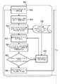
도 8은 일 실시예에 따라, 도 3a 및 도 3b에 대해 설명된 것과 같이, x 평행이동 및/또는 y 평행이동에 의해 이미지 센서와 관련하여 복수 조리개 광학기의 오프셋을 보정하기 위한 방법의 개략적인 흐름도를 보여준다.
도 9는 일 실시예에 따라, 도 4a 및 도 4b에 대해 설명된 것과 같이, 쐐기 에러를 보상하도록 계산 디바이스에 의해 수행될 수 있는 방법의 개략적인 흐름도를 보여준다.
도 10은 일 실시예에 따라, 도 5에 대해 설명된 것과 같이, 내측 이미지 영역의 요 축 또는 z축에 대한 비틀림을 보상하는 방법의 개략적인 흐름도를 보여준다.
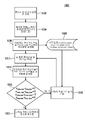
도 11은 일 실시예에 따라, 도 6a, 도 6b, 도 7a 및 도 7b에 대해 설명된 것과 같이, z축 또는 요 축에 따른 평행이동에 의해 복수 조리개 광학기를 정렬하기 위한 방법의 개략적인 흐름도를 보여준다.
도 12는 일 실시예에 따라, 예를 들어 도 8, 도 9, 도 10 또는 도 11 중 임의의 도면의 방법들의 의 견고한 프로세스 흐름을 가능하게 하도록 상기 방법들 중 한 방법 이전에 수행될 수 있는 방법의 개략적 흐름도를 보여준다.
도 13은 일 실시예에 따라 6 자유도를 따라 높은 포지셔닝 정확도들이 유리하게 달성될 수 있는 방법의 개략적인 흐름도를 보여준다.
도 14는 일 실시예에 따라 이미지 영역에 대한 예로서 전역 좌표계와 국소 좌표계들 간의 관계들을 예시하기 위한 개략도를 보여준다.
도 15는 일 실시예에 따라 광 채널들의 2D 정렬을 갖는 이미지 센서 및 복수 조리개 광학기를 포함하는 복수 조리개 대물렌즈에 의해 대상 평면에서 스캔하는 개략적인 표현을 보여준다.
도 16은 일 실시예에 따라 도 15의 관계들을 예시하기 위해 복수 조리개 광학기 및 이미지 센서를 포함하는 개략적인 측단면도를 보여준다.
도 17a는 일 실시예에 따라 이미지 센서와 관련하여 조정되는 복수 조리개 광학기의 개략적인 측단면도를 보여준다.
도 17b는 일 실시예에 따라 도 17a의 상황의 개략적인 상면도를 보여준다.
도 18은 이미지 센서 칩을 형성하기 위한 복수 조리개 이미징 광학기의 조립 레이아웃의 개략적인 이미지를 보여준다.
도 19는 종래 기술에 따라 이미지 센서의 이미지 평면과 복수 조리개 광학기의 정렬에 관한 요건들을 예시하기 위한 개략적인 측단면도를 보여준다.Preferred embodiments of the present invention will be described below with reference to the accompanying drawings.
1 shows a schematic block diagram of a device for relative positioning of a plurality of iris optics comprising a plurality of optical channels in connection with an image sensor in accordance with an embodiment.
Figure 2 shows a schematic block diagram of an upgraded device in comparison to the device of Figure 1 in which a computing device is configured to control a fixed device in accordance with one embodiment.
3A shows a schematic side cross-sectional view of a plurality of stop dioptric devices exhibiting positional errors with respect to an image sensor, according to a negative roll direction according to an embodiment.
Figure 3B shows a schematic top view of the situation of Figure 3A in accordance with one embodiment.
4A shows a schematic side cross-sectional view of a multi-aperture optic for a wedge error with respect to an image sensor, for a pitch axis according to an embodiment.
Figure 4b shows a schematic top view of the situation of Figure 4a in accordance with one embodiment.
Figure 5 shows a schematic top view of a multi-aperture optic tilted with respect to an image sensor at an angle relative to the yaw axis or z axis, according to one embodiment.
6A shows a schematic side cross-sectional view of a plurality of iris dioptric devices exhibiting too small a distance in relation to an image sensor along the yaw axis according to an embodiment.
Figure 6b shows a schematic top view of the situation of Figure 6a in accordance with one embodiment.
FIG. 7A shows a schematic side cross-sectional view of a situation where multiple iris diverters are associated with an image sensor in accordance with one embodiment.
FIG. 7B shows a schematic top view of the situation of FIG. 7A in accordance with one embodiment.
8 is a schematic diagram of a method for correcting an offset of a plurality of aperture optics in association with an image sensor by x translation and / or y translation, as described for Figs. 3a and 3b, according to one embodiment Respectively.
Figure 9 shows a schematic flow diagram of a method that may be performed by a computing device to compensate for wedge errors, as described with respect to Figures 4A and 4B, in accordance with one embodiment.
Figure 10 shows a schematic flow chart of a method for compensating for torsion on the yaw axis or z axis of the inner image region, as described for Figure 5, according to one embodiment.
11 is a schematic flow diagram of a method for aligning a plurality of iris dioptric devices by parallel movement along the z-axis or yaw axis, as described with respect to Figs. 6A, 6B, 7A and 7B, according to one embodiment Lt; / RTI >
FIG. 12 is a flow diagram of a method of performing a process in accordance with an embodiment, which may be performed prior to one of the methods to enable a robust process flow of the methods of any of the Figures 8, 9, 10, And shows a schematic flow chart of the method.
Figure 13 shows a schematic flow diagram of a method by which high positioning accuracy along six degrees of freedom can advantageously be achieved in accordance with an embodiment.
14 shows a schematic diagram for illustrating relationships between a global coordinate system and local coordinate systems as an example for an image region according to an embodiment.
15 shows a schematic representation of scanning in a subject plane by an image sensor having a 2D alignment of optical channels and a plurality of diaphragm objectives comprising a plurality of diaphragm optics according to one embodiment.
Figure 16 shows a schematic side cross-sectional view including a plurality of iris optics and an image sensor to illustrate the relationships of Figure 15 in accordance with one embodiment.
Figure 17A shows a schematic side cross-sectional view of a plurality of diaphragm optics that are adjusted in association with an image sensor in accordance with one embodiment.
Figure 17B shows a schematic top view of the situation of Figure 17A in accordance with one embodiment.
Figure 18 shows a schematic image of an assembly layout of a plurality of iris imaging optics for forming an image sensor chip.
19 shows a schematic side cross-sectional view for illustrating the requirements relating to the alignment of the image plane of the image sensor and the plurality of diaphragm optics according to the prior art.
도면에 의해 본 발명의 실시예들에 대한 상세한 설명들이 아래에 주어지기 전에, 동일하거나 동일한 기능들 또는 동일한 동작들을 갖는 엘리먼트들, 대상들 및/또는 구조들에는 다양한 도면들서 동일한 참조 부호들이 제공되어, 서로 다른 실시예들에 제시된 상기 엘리먼트들의 설명은 상호 교환 가능하고 그리고/또는 상호 적용 가능하다는 점이 주목될 것이다.BRIEF DESCRIPTION OF THE DRAWINGS Before the detailed description of embodiments of the invention is given below by way of illustration, elements, objects and / or structures having the same or similar functions or operations with the same reference numerals It will be noted that the description of the elements presented in different embodiments is interchangeable and / or mutually applicable.
다음에서, 서로 관련하여 여러 이미지 영역들을 갖는 이미지 센서와 복수 조리개 광학기의 정렬에 대한 참조가 이루어질 것이다. 상대적 정렬은 기본적으로 x축, y축 및 z축을 중심으로 한 회전뿐만 아니라, 3개의 공간적 방향들(x, y, z)에 따른 평행이동을 설명하는 6 자유도로 수행될 수 있다. 추가로, 이하의 설명들은 롤 축, 피치 축 및 요 축에 관한 것인데, 이들은 간단한 이해를 위해, 이미지 센서와 관련하여 복수 조리개 광학기의 이상적인 정렬의 경우에 3차원 공간에서 내측 이미지 영역의 x축, y축 및 z축 각각과 평행하게 또는 합동으로 배열된다. 이와 관련하여, x 좌표, y 좌표 및/또는 z 좌표는 이미지 센서의 이미지 영역 내의 각각의 국소 좌표계에 관련된다. 롤, 피치, 및/또는 요 좌표들 또는 방향들은 이미지 센서 및/또는 복수 조리개 광학기가 배열되는 전역 좌표계와 관련된다.In the following, reference will be made to the alignment of the image sensor and the plurality of iris optics having different image areas relative to one another. Relative alignment can be performed in six degrees of freedom, essentially describing parallel movement along three spatial directions (x, y, z) as well as rotation about the x, y, and z axes. In addition, the following description relates to roll axes, pitch axes and yaw axes, which for the sake of simplicity, assume that in the case of ideal alignment of the plurality of diaphragm optics in relation to the image sensor, , parallel to or parallel to the y-axis and the z-axis, respectively. In this regard, the x coordinate, y coordinate and / or z coordinate are associated with each local coordinate system within the image area of the image sensor. The roll, pitch, and / or yaw coordinates or directions are associated with a global coordinate system in which the image sensor and / or the plurality of diaphragm optics are arranged.
이미지 센서의 내부 이미지 영역의 좌표계와 롤 축, 피치 축 및 요 축에 의해 결정된 (전역) 좌표계는 동일한 원점을 그리고 결과적으로는, 예를 들어 복수 조리개 광학기가 전역 원점을 중심으로 비틀어지거나 이동하게 될 때 동일한 피벗점을 포함할 수 있다. 좌표계들은 데카르트 좌표계들로 설명되며, 기본적인 기준으로서 다른 좌표계들을 사용하는 것이 또한 가능하다. 이들은 좌표 변환을 통해 상호 변환 가능할 수도 있다. 아래 설명되는 실시예들은 다른 좌표계들이 기본적인 기준으로 사용되는 경우에도, 이점들에 관해서는 어떠한 제약도 없이 실행 또는 구현될 수 있다.The (global) coordinate system determined by the coordinate system and the roll axis, the pitch axis and the yaw axis of the internal image region of the image sensor has the same origin and as a result, for example, a plurality of aperture optics is twisted or moved around the global origin The same pivot point can be included. Coordinate systems are described by Cartesian coordinates, and it is also possible to use other coordinate systems as a basis of reference. They may be mutually transformable through coordinate transformations. The embodiments described below can be implemented or implemented without any restrictions as to the advantages, even if other coordinate systems are used as the basis of the reference.
도 1은 이미지 센서(16)와 관련하여 여러 개의 광 채널들(14a-c)을 포함하는 복수 조리개 광학기(12)의 상대적 포지셔닝을 위한 디바이스(10)의 개략적인 블록도를 보여준다. 디바이스(10)는 기준 대상(18)을 포함하는데, 이는 광 채널들(14a-c)에서 복수 조리개 광학기(12)에 의해 기준 대상(18)이 채널마다 이미지 영역(22a-c)으로 이미징되도록 배열된다.Figure 1 shows a schematic block diagram of a
디바이스(10)는 복수 조리개 광학기(12)와 이미지 센서(16) 사이의 상대적 위치를 변경하도록 제어 가능한 포지셔닝 디바이스(24)를 포함한다. 유리하게, 포지셔닝 디바이스는 이미지 센서(16)와 관련하여 3차원 공간에서 6 자유도에 따라 복수 조리개 광학기(12)를 이동시키도록 구성된다. 그러나 포지셔닝 디바이스(24)가 3차원 공간에서 이미지 센서(16)를 이동시키도록 구성되는 것이 또한 실행 가능하다. 더욱이, 포지셔닝 디바이스가 3차원 공간에서 6 미만의 자유도를 따라 복수 조리개 광학기(12) 또는 이미지 센서(16)를 이동시키는 것이 생각될 수 있다.The
디바이스(10)는 기준 대상(18)의 이미지들에서, 적어도 3개의 이미지 영역들(22a-c)에서의 기준 대상(18)의 실제 위치들을 결정하고 실제 위치들과 위치들의 비교에 기초하여 포지셔닝 디바이스(24)를 제어하도록 구성된 계산 디바이스(26)를 더 포함한다. 위치들은 기준 대상(18)이 조정된 상태, 예를 들어 이미지 영역들(22a-c)(국소)의 또는 이미지 센서(16)(전역)의 중심 위치들로 이미징되는 기준 위치들일 수도 있다.The
예를 들어, 계산 디바이스(26)는 이미지 영역들(22a-c)에서 각각의 이미지를 수신하여 평가하도록 구성된다. 이미지 센서는 전하 결합 디바이스(CCD: charge-coupled device), 상보형 금속 산화물 반도체(CMOS: complementary metal-oxide semiconductor), 또는 임의의 다른 디지털 이미지 센서일 수도 있다.For example, the
이미지 영역들(22a-c)은 이미지 센서(16)에 또는 이미지 센서(16) 내에서 이들이 서로 이격되도록 배열될 수 있다. 대안으로, 이미지 영역들(22a-c)은 또한 예를 들어, 각각의 픽셀들을 어드레싱하는 서로 다른 방식들에 의해 서로 구별 가능할 수 있는 연속 픽셀 매트릭스의 일부일 수도 있다. 예를 들어, 이미지 영역들(22a-c) 각각은 기준 대상(18)의 일부를 캡처하도록 구성된다. 각각의 부분에서, 예를 들어, 테스트 패턴 또는 그 일부는 각각의 부분의 각각의 테스트 패턴이 각각의 이미지 영역(22a-c)에서 이미징되도록 배열될 수 있으며; 일단 배열되면, 테스트 패턴은 이미지 영역들(22a-c) 중 하나, 몇몇 또는 모두에 대해 캡처될 수 있도록 배치될 수 있다.The
복수 조리개 광학기(12), 이미지 센서(16) 및 기준 대상(18)의 컴포넌트들 중 2개에 대해 정해진 정렬, 예를 들어 이미지 센서(16)와 관련하여 또는 복수 조리개 광학기(12)와 관련하여 기준 대상(18)의 정해진 정렬 및/또는 포지셔닝은, 복수 조리개 광학기(12)가 이미지 센서(16)와 관련하여 에러 없는 위치 또는 정렬을 갖거나 허용 가능한 공차들 내에 배열될 때 이미지 영역들(22a-c)에서 기준 대상(18)으로부터 캡처될 타깃 이미지의 평가를 가능하게 한다. 따라서 복수 조리개 광학기(12)와 이미지 센서(16)의 상대적 정렬은 실제 위치들과 (타깃) 위치들의 비교를 기초로 이루어질 수 있다. 이는 계산 디바이스가 다른 이미지 영역들에서의 실제 위치들에 대한 이미지 영역의 실제 위치의 비교에 기초하여 포지셔닝 디바이스를 제어하도록 구성된다는 것을 의미한다.For example, with respect to the
캡처된 이미지의 콘트라스트에 기초한 정렬과 비교하여, 이것은 복수 조리개 광학기(12)의 초점 심도 범위에 기초한 콘트라스트가 부정확하거나 심지어 잘못된 결과들로 이어지기 때문에 높은 정밀도를 가능하게 한다. 기준 대상(18)과 이미지 센서(16) 사이의 거리는 예를 들어, 2m보다 작거나, 1m보다 작거나, 또는 50㎝보다 작을 수도 있다. 원칙적으로, 기준 대상(18)과 이미지 센서(16) 사이의 거리는 이미지 센서(16)의 구현, 복수 조리개 광학기(12) 및/또는 예상된 배율 또는 해상도에 따라, 애플리케이션에 의존할 수 있다.Compared to the alignment based on the contrast of the captured image, this enables high precision because the contrast based on the depth of focus range of the
도 2는 계산 디바이스(26)가 고정 디바이스(28)를 제어하도록 구성된다는 점에서 디바이스(10)와 비교하여 업그레이드되는 디바이스(20)의 개략적인 블록도를 보여준다. 고정 디바이스(28)는 복수 조리개 광학기(12)와 이미지 센서(16) 사이에 배열된 접착제(32)를 경화시키도록 구성된다. 예를 들어, 이미지 센서(16)와 관련하여 복수 조리개 광학기(12)가 포지셔닝될 때, 상기 복수 조리개 광학기(12)는 접착제(32)에 의해 이미지 센서(16)와 접촉될 수 있다. 접착제(32)는 예를 들어, 자외선(UV: ultraviolet) 광으로 경화될 수 있는 접착제일 수 있다. 고정 디바이스(28)는 예를 들어, 접착제(32)를 경화시기 위해 계산 디바이스(26)에 의해 구동되는 것에 기초하여 UV 광을 방출하는 UV 광원일 수도 있다. 대안으로, 접착제(32)는 열경화성 접착제일 수도 있고, 고정 디바이스(28)가 열원으로서 구성되는 것이 가능하다. 원칙적으로, 고정 디바이스(28)는 이미지 센서(16)와 복수 조리개 광학기(12) 사이에 상이한 기계적 연결, 예를 들어 클램핑, 나사, 리벳 연결 및/또는 납땜 연결을 설정하도록 또한 구성될 수도 있다.2 shows a schematic block diagram of a
상기에서 유리한 것은 복수 조리개 광학기(12)와 이미지 센서(16) 사이에 설정된 상대적 위치가 어떠한 추가 중간 단계도 없이 가능하게 고정될 수 있으며, 따라서 포지셔닝 에러들의 추가가 방지될 수 있다는 점이다. 대안으로, 고정 디바이스(28)는 또한 디바이스(20)의 일부일 수도 있다.Advantageous in this respect is that the relative position set between the plurality of
기준 대상(18)은 기준 영역들(33a-c)에 배열된 서브패턴들 및/또는 마킹들(35a-c) 형태의 패턴을 가져, 각각의 경우에 광 채널들(14a-c) 중 하나에 의해 하나의 서브패턴(35a-c)이 캡처되어 마커로서 각각의 이미지 영역(22a-c)으로 이미징된다. 이는 복수 조리개 광학기의 후속 조정을 위해 기준 대상(18)에 대한 기준 패턴과 이미지 센서(16)의 정렬을 가능하게 하는데, 예를 들어, 광학 법칙들 및 제로 편차 복수 조리개 광학기를 사용하여 정렬이 수행되는 것이 가능하다The
기준 대상에 대한 테스트 패턴의 이용은 예를 들어, 이미지 영역들(22a-c)에서의 에지 검출에 기초하여 계산 디바이스(26)에 의한 이미지 영역들(22a-c)의 평가를 가능하게 한다. 이를 위한 알고리즘들은 정확하고 견고한 방식으로 이용될 수 있다. 기준 대상에 적합한 마킹들은 예를 들어, 기하학적 배열을 따르는 십자형들, 원들 또는 H 구조들일 수 있다. 원칙적으로, 다른 구조들, 그러나 바람직하게는 점 구조들과 관련하여 긴 에지 길이들을 나타내는 구조들이 또한 배열될 수도 있다. 위의 설명들에서 마커들의 배열은 항상 x 구성으로 설명되었지만, 마커들이 스타형 배치(constellation), 원형 배치 등에서 발생함으로써, 마커들이 가능하게는 더 많거나 더 적게 투사되고 그리고/또는 이미지 센서 상의 다른 이미지 영역들이 되는 것이 또한 실행 가능하다. 앞서 설명한 실시예들은 위치들의 결정 및 위치 편차들의 평가의 간단한 적응을 가능하게 하여, 상이한 테스트 패턴들이 용이하게 적용될 수 있게 한다.The use of a test pattern for the reference object enables evaluation of the
계속되는 설명들은 계산 디바이스(26)로부터 포지셔닝 디바이스(24)로 전달되어 각각의 복수 조리개 광학기가 이미지 센서와 관련하여 3차원 공간에서 이동하게 되도록 포지셔닝 디바이스(24)를 구동시키기 위한 구동 단계들에 관한 것이다. 아래 설명되는 에러 보상 단계들은 유리하게는 이미지 센서와 관련하여 6 자유도로 복수 조리개 광학기의 정확한 정렬을 가능하게 하는 순서로 설명될 것이다. 포지셔닝 디바이스(26)는 대안으로, 설명된 에러 보상 단계들 중 하나 이상만을 수행하고 그리고/또는 수정된 시퀀스에서 이러한 단계를 수행하도록 구성될 수도 있다.Subsequent descriptions relate to driving steps for driving the
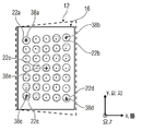
도 3a는 이미지 센서(16)와 관련하여 음의 롤 방향에 따라 위치 에러를 나타내는 복수 조리개 광학기(12)의 개략적인 측단면도를 보여준다. 도 3b는 이러한 상황의 개략적인 상면도를 보여준다. 도 3a에서, 이미지 센서(16)는 인쇄 회로 기판(36)에 배치되고 그와 접촉하여, 이미지 센서(16)로부터의 이미지 영역들(22a-f)의 캡처된 이미지들이 인쇄 회로 기판(36)에서 계산 디바이스에 의해 획득될 수 있다.3A shows a schematic side cross-sectional view of a plurality of
음의 롤 방향을 따른 횡 방향 위치 에러는 이미지 센서(16)와 복수 조리개 광학기(12) 사이의 위치들의 차(ΔR)를 야기한다. 광학 디바이스의 마이크로 이미지 중심들, 즉 광 채널들(14a-f)의 중심들(37)은 예로서, 음의 롤 방향을 따라 위치들의 차(ΔR)만큼 선형 시프트를 겪었다.A transverse position error along the negative roll direction causes a difference (DELTA R) of the positions between the
기준 대상은 테스트 대상 구조를 포함한다. 이를 위해, 예를 들어, 하나 이상의 십자들 "+"의 형태인 마킹들이 각각의 이미지 영역들(22a-e)에서 광 채널들(14a-f)에 의해 마커들(38a-e)로서 캡처되는 마킹들, 예를 들어 기준 대상 상의 마킹들(35)로서 배열된다.The reference object includes the test object structure. To this end, markings, for example in the form of one or more crosses "+", are captured as
롤 축, 피치 축 및 요 축에 걸친 좌표계의 좌표 원점은 내측 이미지 영역(22e)의 국소 x/y/z 좌표계의 원점에 배열될 수 있다. 계산 디바이스, 예를 들어 계산 디바이스(26)는 이미지 영역(22e)에 관련하여 마킹(38e)을 포커싱하도록 구성된다. 이를 위해, 계산 디바이스는 포지셔닝 디바이스가 이미지 영역(22e)에 대해 z축을 따라 이미지 센서(16)와 관련하여 복수 조리개 광학기(12)의 거리를 변화시켜, 마커(38e)가 이미지 영역(22e)에 포커싱되게 포지셔닝 디바이스, 예를 들면 포지셔닝 디바이스(24)를 구동하도록 구성될 수도 있다. 이것은 계산 디바이스가 내측 이미지 영역(22e)에 대한 실제 위치(마커(38)가 이미징되는 위치)의 패턴 거리들의 배율 거리의 측정치를 결정하고, 배율 거리가 배율 거리 타깃 값에 도달하도록 포지셔닝 디바이스가 z축 또는 요 축을 따라 복수 조리개 광학기(12)를 시프트하게 포지셔닝 디바이스를 제어하도록 구성됨을 의미한다. 예를 들어, 계산 디바이스(26)는 내측 이미지 영역(22e)의 하나 또는 두 축들(x 및/또는 y)을 따라 패턴(38e)의 확장을 결정하고 이를 비교 값과 비교하도록 구성될 수 있다. 마커(38e)의 캡처된 패턴이 더 크거나 더 작다면, 복수 조리개 광학기(12)와 이미지 센서(16) 사이의 거리가 각각 증가 또는 감소될 수 있다.The coordinate origin of the coordinate system over the roll axis, the pitch axis and the yaw axis can be arranged at the origin of the local x / y / z coordinate system of the
계산 수단은 예를 들어, 이후에 패턴 편차에 기초하여 내측 이미지 영역(22e)에 대한 마커(38e)의 실제 위치의 횡 방향 차이의 측정치를, 예를 들어 x축과 y축의 좌표 원점에 대해 결정하도록 구성된다. 이는 계산 디바이스가 x축을 따른 횡 방향 차이의 측정치 및 y축을 따른 패턴 편차에 대한 횡 방향 차이의 측정치를 결정하도록 구성된다는 것을 의미한다. 계산 수단은 횡 방향 차이들이 각각의 타깃 값에 도달하게 포지셔닝 디바이스를 제어하도록 구성된다.The calculation means may determine, for example, a measure of the lateral difference of the actual position of the
간단히 말하면, 이것은 횡 방향 차이 타깃 값들에 도달하게 될 때까지 포지셔닝 디바이스가 (롤 축 및/또는 피치 축을 따라 전역 좌표계에서) x축 및/또는 y축을 따라 복수 조리개 광학기(12) 및/또는 이미지 센서(16)를 시프트한다는 것을 의미한다. 예를 들어, 마커(38e)를 이미지 영역(22e)의 국소 좌표계의 좌표 원점으로 보호함으로써 하나 또는 두 횡 방향 차이 타깃 값들에 도달할 수 있다. 공차 범위는 예를 들어, 허용 가능한 편차, 예를 들어 하나 또는 2개의 픽셀들씩의 시프트로 또는 달성 가능한 측정 정확도로 정의될 수 있다. 달성 가능한 측정 정확도는 예를 들어, 2개의 픽셀들의 거리에 기초할 수 있어, 편차가 픽셀 거리보다 더 작고 가능하게는 검출되지 않는, 이미지 영역(22e)의 좌표 원점에 대한 마커(38e)의 투사 편차는 각각의 횡 방향 차이 타깃 값에 도달하도록 충분히 정확한 것으로 간주되지 않을 수 있다.Briefly, this means that the positioning device is capable of moving the plurality of iris
인쇄 회로 기판(36)과 복수 조리개 광학기(12) 사이에 접착제(32)가 배열되어, 이미지 센서(16)와 관련하여 복수 조리개 광학기(12)의 설정된 위치가 고정될 수 있다.An adhesive 32 may be arranged between the printed
즉, 도 3a과 도 3b는 x 평행이동에 의한 대물렌즈의 오프셋을 보여준다. y 평행이동으로 인한 위치 에러는 해당 단면도에서 동일한 결과 이미지를 생성할 수 있다.3a and 3b show the offset of the objective lens by x translation. Position errors due to y translation can produce the same result image in the cross section.
모든 마이크로 이미지 중심들(점선 원들의 중심)은 롤 축을 따라 거리(ΔR)만큼 각각의 이미지 영역들의 중심들에 대해 x 및/또는 y 차원(들)에서 선형으로 시프트된다. 정렬은 예를 들어, 도 15에 대한 기준 대상에 대한 위치들에 대해 설명된 바와 같이 각각의 이미지 영역의 상대적 위치를 나타내는 좌표들(x0,0, y0,0, xi,j 및/또는 yi,j)을 포함하는 중앙 광 채널(14e) 내의 테스트 대상 구조의(즉, 마커(38e)의) 결정된 이미지 좌표들에 의해서만 가능하게 이루어진다.All the micro image centers (the center of the dotted circles) are linearly shifted in the x and / or y dimension (s) with respect to the centers of the respective image areas by the distance [Delta] R along the roll axis. Alignment may be performed, for example, with coordinates (x 0,0 , y 0,0 , x i, j and / or x 0,0,0) representing the relative position of each image area as described for locations with respect to the reference object for FIG. ( I. E., Of
처음에, 테스트 대상 구조의 이미지가 중앙 광 채널에 포커싱된다(z축을 따라 평행이동). 이후에, 중심 테스트 대상의 이미지의 기하학적 중심이 이미지 매트릭스의 중심에, 즉 전역 좌표계의 원점(O)에 위치할 때까지, 대물렌즈가 x축을 따라 그리고/또는 y축을 따라 시프트된다. 테스트 대상 구조의 측정된 이미지 좌표에 대해 다음의 동등한 조건들이 충족될 수 있는데:Initially, the image of the structure under test is focused on the central optical channel (parallel translation along the z-axis). Thereafter, the objective lens is shifted along the x-axis and / or along the y-axis until the geometric center of the image to be tested is located at the center of the image matrix, i.e. at the origin O of the global coordinate system. For the measured image coordinates of the structure under test, the following equivalent conditions may be met:
![]()
![]()

여기서 ri,j는 예를 들어, 전역 이미지 좌표계에서 인덱스들(i, j)을 갖는 비트 필드의 반경 좌표를 기술한다.Where r i, j describes, for example, the radial coordinates of the bit field with indices (i, j) in the global image coordinate system.
rimax, rjmax, r-imax 및 r- jmax는 +i, -i, +j 및 -j에서 각각, 마커들이 이미징되는 그러한 이미지 영역들에 대한 최대 위치를 포함하는 해당 외측 이미지 영역의 방사 좌표와 관련된다.r imax, jmax r, r and r -imax - jmax is + i, -i, + j, and -j, respectively from, the radial coordinate of the image area outside of the markers are included up to the location of such an image region being imaged Lt; / RTI >
"0"의 결과는 가능하게는, 측정된 이미지 좌표들의 차이에 의해 실제로 달성되지 않을 수도 있기 때문에, 편차들이 공차 범위 내에 있도록, 원하는 조립 정밀도에 해당하는 양(배율 거리 타깃 값 및/또는 횡 방향 차이 타깃 값들)으로 결과를 반올림한 것, 또는 규칙으로부터 발생하는 차이보다 더 높은 대응하는 제어 값이 정의된다. 이는 또한 아래 설명되는 미세 정렬 단계들의 조건들에 적용된다.Since the result of "0 " is possibly not actually achieved by the difference in measured image coordinates, the amount corresponding to the desired assembly precision (the magnification distance target value and / or the lateral direction Difference target values), or a corresponding control value that is higher than the difference arising from the rule is defined. This also applies to the conditions of the microarray steps described below.
이미지 센서에 대한 복수 조리개 광학기의 정렬뿐만 아니라, 이와 관련하여 정렬이 설명되는 도 3a와 도 3b는 아래에 설명되는 조정 단계들 중 하나, 몇몇 또는 임의의 조정 단계에 선행하는 개략적 정렬로서 수행될 수 있다.3A and 3B, in which the alignment is described in relation to the alignment of the plurality of aperture optics for the image sensor, is performed as a schematic alignment preceding one, some or any of the adjustment steps described below .
도 4a는 이미지 센서(16)와 관련하여 피치 축에 대해 쐐기 에러(ΔtN)를 나타내는 복수 조리개 광학기(12)의 개략적인 측단면도를 보여준다. 즉, 피치 축에 관련하여, 복수 조리개 광학기(12)는 이미지 센서(16)에 대해 각도(ΔtN)만큼 기울어진다. 도 4b는 도 4a의 상황의 개략적인 상면도를 보여준다. 기준 대상에 대한 테스트 패턴은 중심 이미지 영역(22a)에 대해 센터링되고 포커싱되는데, 이는 x축 및 y축에 관한 거리 타깃 값 및 횡 방향 차이 타깃 값들에 도달하게 되도록 마커(38e)가 이미지 영역(22e)으로 투사되는 것을 의미한다. 쐐기 에러는 마커들(38a-d)이 x 및/또는 y 방향(들)으로 편차들을 나타내는 결과를 야기한다.4A shows a schematic side cross-sectional view of a
계산 디바이스는 이미지 영역들(22a-d)의 중심들, 예컨대 기하학적 중심들에 대한 마커들(38a-d)의 시프트들을 결정하도록 구성된다. 예를 들어, 복수 조리개 광학기(12)의 초점 위치가 이미지 센서(16)와 관련하여 에러들을 나타낸다면, 이미지 영역들(22a-d)과 관련하여 마커들(38a-e)의 거리들이 각각의 쌍에 대해 동일하다는 사실에 의해 계산 디바이스에 의해 쐐기 에러가 결정될 수 있다 예를 들어, 마커들(38a와 38c, 38b와 38d) 각각의 거리들이 이미지 영역들(22a-d)의 각각의 중심들에 대해 동일할 때까지 복수 조리개 광학기(12)가 롤 축을 중심으로 회전되도록 계산 디바이스가 포지셔닝 디바이스를 구동한다는 점에서, 롤 축을 중심으로 한(x축을 중심으로 한 - tx) 복수 조리개 광학기(12)의 회전시 한 쌍이 보상될 수 있다.The computing device is configured to determine shifts of the
추가로, 마커들(38a와 38b, 38c와 38d) 각각의 거리들이 이미지 영역들(22a-d)의 각각의 중심들에 대해 동일할 때까지 포지셔닝 디바이스가 복수 조리개 광학기(12)를 회전시키도록 계산 디바이스가 포지셔닝 디바이스를 구동한다는 점에서, 피치 축을 중심으로 한(y축을 중심으로 한 - ty) 회전에 의해 야기되는 쐐기 에러가 보상될 수 있다. 이는 이미지 영역들(22a-d)의 중심들에 대한 마커들(38a-d)의 각각의 거리들이 각각의 외측 이미지 영역(22a-d)에 대한 실제 위치의 패턴 거리들의 쐐기 에러 차이의 측정치를 포함할 수 있으며, 계산 디바이스는 상기 쐐기 에러 차이를 결정하도록 구성된다는 것을 의미한다. 롤 축 또는 피치 축과 관련하여 복수 조리개 광학기(12)를 기울임으로써, 쐐기 에러 차이들이 앞서 설명한 바와 같이, 공차 범위 내의 0 값 주위에 있을 수 있는 타깃 롤 값 또는 타깃 피치 값에 도달하도록 이러하나 차이들이 변경될 수 있다. 쐐기 에러 보상 전에, 도 3a와 도 3b에 대해 설명한 개략적 정렬이 수행될 수 있다.Additionally, the positioning device rotates the plurality of
즉, x축을 중심으로 한 비틀림(tx) 동안 그리고/또는 y축을 중심으로 한 비틀림(ty) 동안 복수 조리개 광학기(12)를 정렬하기 위해, 이는 쐐기 에러 보상 동안을 의미하며, 처음에 테스트 대상 구조의 이미지가 중앙 광 채널에 포커싱되는데, 즉 z축을 따른 평행이동이 수행된다. 그 후, 이미지는 x축 및/또는 y축을 따라 시프트됨으로써 이미지 원점(O) = (0,0)으로 센터링된다. 쐐기 에러는 각각의 이미지 원점들로부터 코너 채널들에서, 즉 외측 이미지 영역들(22a-d)의 테스트 대상 구조들의 이미지들의 측정된 위치들의 서로 다른 방사상 거리들을 야기한다. 이는 외측 이미지 영역들(22a-d)에 대한 다음 조건들이 충족될 때까지 복수 조리개 대물렌즈를 x축 및/또는 y축(롤 축 및/또는 피치 축)에 의해 회전시킴으로써 적어도 부분적으로 보정될 수 있는데:That is, to align the plurality of
x축을 중심으로 한 회전시(tx): ![]()
![]()
![]()
![]()
![]()
![]()
![]()
![]()
y축을 중심으로 한 회전시(ty): ![]()
![]()
![]()
![]()
![]()
![]()
![]()
![]()
쐐기 에러들은 4개의 외측 이미지 영역들에 대해 롤 축(롤 축에 대한 비틀림)에 대해 그리고/또는 피치 축(피치 축에 대한 비틀림)에 대해 축 대칭이 될 수 있다.The wedge errors may be axisymmetric with respect to the roll axis (twist to roll axis) and / or to the pitch axis (twist to pitch axis) for the four outer image areas.
따라서 도 4a와 도 4b는 y축에 대한 비틀림(y 쐐기 에러)에 의한 대물렌즈의 오프셋을 보여주는데 - x축에 대한 비틀림은 대응하는 대등한 측면도에서 동등한 결과 이미지를 생성할 수 있다. 양 또는 음의 회전 각에 대한 비틀림의 결과들은 또한 상기 설명들과 유사하게 결정 및/또는 보상될 수도 있다.Thus Figures 4a and 4b show the offset of the objective by torsion (y-wedge error) on the y-axis - the twist on the x-axis can produce an equivalent result image in the corresponding equivalent side view. The results of twisting for positive or negative rotation angles may also be determined and / or compensated similarly to the above description.
도 5는 중심 이미지 영역(22e)의 요 축 또는 z축에 관한 각도(δ)로 이미지 센서(16)와 관련하여 기울어진 복수 조리개 광학기(12)의 개략적인 상면도를 보여준다. 계산 디바이스는 예를 들어, 각각의 외측 이미지 영역들(22a-d)의 중심들로부터 마커들(38a-d)의 거리를 결정하도록 구성된다. 각도(δ)만큼의 회전을 기초로, 마커들(38a-d) 각각은 각각의 중심으로부터의 거리를 갖는다. 상기 거리는 이미지 영역들(22a, 22b)에 대한 각각의 x 방향을 따라 더 또는 덜 동일하다. 마찬가지로, 이미지 영역들(22c, 22d)에 대한 거리는 x 방향으로 동일하다. 각각의 이미지 영역의 y 방향에서, 거리는 이미지 영역들(22a와 22c, 22b와 22d)에 대해 각각 개략적으로 동일하다. 각각 이미지 영역들(22a와 22b, 22c와 22d)에 대한 x 거리들의 측정뿐만 아니라, 각각 이미지 영역들(22a와 22c, 22b와 22d)에 대한 y 방향을 따른 거리들의 측정은 외측 이미지 영역들(22a-d) 각각에 대한 패턴 편차의 회전 차의 측정치로서 계산 디바이스에 의해 결정될 수 있다.Figure 5 shows a schematic top view of a
계산 디바이스는 포지셔닝 디바이스가 요 축을 중심으로 복수 조리개 광학기(12) 및/또는 이미지 센서(16)를 회전시키게 포지셔닝 디바이스를 제어하도록 구성된다. 회전 차(δ)는 예를 들어, 공차 범위 내에서 0인 타깃 회전 값에 도달할 때까지 요 축을 중심으로 한 회전에 의해 감소될 수 있다. 회전 에러는 전역 좌표계의 원점과 관련하여 4개의 외측 이미지 영역들(22a-d)에 대해 회전 대칭일 수 있다.The computing device is configured to control the positioning device such that the positioning device rotates the plurality of iris optics (12) and / or the image sensor (16) about the yaw axis. The rotational difference delta can be reduced, for example, by rotation about the yaw axis until a target rotational value of zero is reached within a tolerance range. The rotation error may be rotationally symmetric with respect to the four
즉, 중심 이미지 영역의 z축에 대한 비틀림(tz)시, 이것은 z 비틀림을 보정하기 위해, 정렬이 처음에 중앙 광 채널에서 테스트 대상 구조의 이미지를 포커싱(z축을 따라 평행이동)하고, 그 후에 그 이미지를 x축 및/또는 y축을 따라 시프트함으로써 이를 이미지 원점(O) = (0,0)에서 센터링하는 것을 수반함을 의미한다. z축에 대한 비틀림은 각각의 국소 좌표계에서 테스트 구조들(38a-d)의 이미지들의 중심 내측 이미지 영역(22e)에 대해 대칭적으로 포지셔닝된 광 채널들(14a-d)에 대해 양이 같은 시프트를 야기하는데, 즉:That is, at torsion (tz) with respect to the z-axis of the central image area, this will cause the alignment to initially focus the image of the structure under test (parallel translation along the z-axis) in the central optical channel, and then ( O ) = (0, 0) by shifting the image along the x- and / or y-axis. The twist about the z-axis is a positive shift for the
인덱스(i, j)를 갖는 각각의 외부 광 채널(14a-e) 및/또는 연관된 이미지 영역(22a-e)에서 방사상 국소 좌표들(![]()
![]()
![]()
![]()
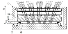
도 6a는 이미지 센서(16)와 관련하여 요 축을 따라 타깃 값(Gtarget)과 비교하여 너무 작은 거리(G)를 포함하는 복수 조리개 광학기(12)의 개략적인 측단면도를 보여준다. 거리(G)는 복수 조리개 광학기(12)에서, 복수 조리개 광학기(12)의 스퓨리어스 광 억제 구조(39)의, 이미지 센서(16)를 향하는 표면과 스퓨리어스 광 억제 구조(39)를 향하는 이미지 센서(16)의 표면 사이의 거리와 관련될 수 있다. 대안으로, 거리(G)는 또한, 복수 조리개 광학기(12)를 향하는 이미지 센서(16)의 표면과 복수 조리개 광학기(12)의 상이한 기준 평면, 예를 들어 대상 영역 또는 이미지 센서를 향하는 렌즈 평면, 또는 다른 기준 평면의 표면 사이의 거리와 관련될 수도 있다. 더욱이, 거리(G)는 또한 이미지 센서(16)에 대한 상이한 기준 평면에, 예를 들어 이미지 센서(16)가 인쇄 회로 기판(32)에 배치되는 표면에 관련될 수 있다. 타깃 값(Gtarget)은 복수 조리개 광학기(12)의 후방 초점 거리에 그리고/또는 이미지 평면에 투사되는 이미지의 원하는 또는 최적 선명도가 얻어질 수 있는 복수 조리개 광학기(12)와 이미지 센서(16) 사이의 거리(G)에 관련될 수 있다. 타깃 값(Gtarget)은 거리 타깃 값으로 지칭될 수 있다. 대안으로 또는 추가로, 타깃 값(Gtarget)은 복수 조리개 광학기(12)와 이미지 센서(16) 사이의 거리의 임의의 다른 타깃 값에 관련될 수도 있다. 거리 타깃 값(Gtarget)과 거리(G) 간의 편차, 예를 들어 차이는 예를 들어, ΔG = G-Gtarget 또는 ΔG = Gtarget - G로 표현되는 거리들의 차이(ΔG)로 지칭될 수 있다. 거리들의 차이가 0과는 다른 값을 갖는다면, 이는 결정 가능한 배율 에러를 야기할 수 있는데, 이는 대상 영역이 가능하게는 너무 큰 또는 너무 작은 이미지로 이미징됨을 의미한다.6A shows a schematic side cross-sectional view of a plurality of
도 6b는 이 상황에 대한 복수 조리개 광학기(12) 및 이미지 센서(16)의 개략적인 상면도를 보여준다. 예를 들어, 거리들의 차이(ΔG)가 개략적으로 0의 값을 갖도록 정확하게 설정된 거리(G)와 비교하여, 마커들(38a-e)을 포함하는 기준 대상은 너무 작은 거리(G) 그리고 결과적으로 0과는 다른(예를 들면, 0보다 더 작은) 값을 갖는 거리들의 차이(ΔG)를 기초로 한 확대 방식으로 표현되거나 이미징될 수 있다. 이것은 외측 이미지 영역들(22a-d)에 이미징된 마커들이 중앙의 내측 이미지 영역(22e)의 중심에 대해 전역 롤 축 및 피치 축을 따라 증가된 방사 거리를 포함하는 결과를 가져온다. 각각의 국소 x/y 좌표계들과 관련하여, 이것은 마커(38a)가 이미지 영역(22a) 내에서 음의 x 및 양의 y 값들로 시프트되고, 마커(38b)가 양의 x 및 양의 y 값들 쪽으로 시프트되고, 마커(38c)가 음의 x 및 음의 y 값들 쪽으로 시프트되고, 마커(38d)가 양의 x 및 음의 y 값들 쪽으로 시프트됨을 의미한다. 대응하는 시프트는 각각 이미지 영역들(22b와 22d, 22a와 22c)에 대한 각각의 x 방향을 따라서는 물론, 각각 이미지 영역들(22a와 22b, 22c와 22d)에 대한 각각의 y 방향을 따라서도 더 많이 또는 더 적게 동일하여, 여기서는 국소 및/또는 전역 좌표 원점들에 대한 대칭이 역시 존재한다.6B shows a schematic top view of the multi-stop
도 6a를 참조하면, 계산 디바이스는 예를 들어, 외측 이미지 영역들(22a-d) 중 적어도 하나, 몇몇 또는 각각에 대해, 각각의 마커(38a-d)가 이미징되는 방사상 국소 좌표들을 을 결정함으로써 거리들의 차이들(ΔG)의 측정치를 결정하도록 구성된다. 각각의 마커(38a-d)가 각각의 이미지 영역(22a-d)의 각각의 중심(x = 0, y = 0) 외부에 포지셔닝되는 것을 의미하는 0 값으로부터의 편차는 계산 디바이스에 의해 패턴 편차의 거리들의 차이(ΔG)의 측정치로서 결정될 수 있다. 계산 디바이스는 이미지 영역들(22a-d)의 거리의 차이들(ΔG)이 타깃 거리 값(Gtarget)에 도달하도록, 예를 들면, 마커들(38a-d)이 이미지 영역들(22a-d)의 중심들에 이미징될 때까지 이러한 시간 동안 거리가 변경 또는 변화된다는 점에서, 포지셔닝 디바이스가 요 축을 따라 복수 조리개 광학기(12)를 시프트하게 포지셔닝 디바이스를 제어하도록 구성된다.Referring to Figure 6a, the computing device determines, for at least one, some, or each of the
. 거리들의 차이 타깃 값은 예를 들어, 거리들의 차이(ΔG)에 대한 공차 범위 내의 0 값 주위에 또는 공차 범위 내의 타깃 값(ΔGtarget) 주위에 있을 수 있다. 예를 들어, 도 4a 및 도 4b에 대해 설명된 바와 같이 임의의 기울기 에러들이 보상되었다면, 거리들의 차이(ΔG)는 외측 이미지 영역들(22a-d)에 대해 동일할 수도 있다.. The difference target values of the distances may be, for example, around a zero value in the tolerance range for the difference of the distances (? G) or around the target value (? G target ) in the tolerance range. For example, if any tilt errors have been compensated for as described with respect to Figures 4A and 4B, the difference in distances [Delta] G may be the same for
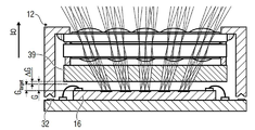
도 7a는 이미지 센서(16)와 관련한 복수 조리개 광학기(12)가 타깃 값(Gtarget)과 비교하여 너무 큰 거리(G)를 포함하는, 즉 마커들(38a-d)이 각각의 경우에 내측 이미지 영역(22d)의 방향으로 시프트되는 상황의 개략적인 측단면도를 보여준다. 도 7b는 도 7a의 상황의 개략적인 상면도를 보여준다. 계산 디바이스는 거리(G) 그리고 결과적으로는 거리들의 차이(ΔG)의 측정치가 감소되어 거리의 차이들(ΔG)이 (거리의 차이) 타깃 값에 도달하는 식으로 포지셔닝 디바이스를 제어하여 복수 조리개 광학기(12) 및/또는 이미지 센서(16)를 이동시키도록 구성된다.Figure 7a shows that the plurality of
즉, 타깃 초점 거리와 실제 초점 거리의 차이는 가능한 한 감소되어야 한다. 이를 위해, 이미지 영역(22a)에서의 배율 결정이 사용될 수 있다. 제조 공차들로 인해, 타깃 초점 길이 및 이에 따라 광학기의 후방 초점 거리에 대한 타깃 값에 정확하게 도달하지 못한다면, 개략적 정렬 후에 이미지 영역(22e)의 배율이 측정될 수 있고, 실현된 배율의(또는 이로부터 유도된 초점 길이의) 지식을 사용함으로써 미세 정렬을 위한 테스트 패턴이 그에 따라 적응될 수 있다. 후방 초점 거리의 정확한 수치값은 가능하게 무시될 수 있다.That is, the difference between the target focal length and the actual focal length should be reduced as much as possible. To this end, the determination of magnification in the
이를 위해, 예를 들어 z축을 따른 평행이동 동안의 정렬(거리 에러의 보정) 동안, 테스트 대상 구조의 이미지는 처음에 중앙 광 채널에 대략적으로 포커싱되고(z축을 따른 평행이동), 이후에 z축 및/또는 y축을 따라 시프트됨으로써 이미지 원점(O) = (0,0)에 센터링된다. 이미지 센서와 관련하여 복수 조리개 대물렌즈의 z거리가 너무 작은 경우, 어레이 코너들에 있는 테스트 구조들의 이미지들은 (크기 면에서) 더 큰 전역 이미지 좌표들 쪽으로 시프트된다. 거리가 너무 큰 경우, 상기 시프트가 반전되어, 테스트 구조들의 이미지들은 (크기 면에서) 더 작은 전역 이미지 좌표들 쪽으로 시프트된다. 이에 따라, z 거리는 테스트 구조들의 이미지들이 각각의 채널들의 중심들 내에 놓일 때까지 그리고/또는 공차 범위를 고려하면서 다음 조건이 충족될 때까지 달라진다:To this end, during alignment (correction of distance error) during, for example, parallel movement along the z-axis, the image of the structure under test is initially focused approximately at the central optical channel (parallel movement along the z-axis) And / or shifted along the y-axis, thereby centering the image origin ( O ) = (0, 0). If the z-distances of the multiple iris objective in relation to the image sensor are too small, the images of the test structures in the array corners are shifted towards larger global image coordinates (in terms of size). If the distance is too large, the shift is reversed so that the images of the test structures are shifted toward smaller global image coordinates (in terms of size). Accordingly, the z-distance varies until the images of the test structures are within the centers of the respective channels and / or the following conditions are satisfied, taking into account the tolerance range:
![]()
![]()
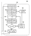
도 8은 도 3a 및 도 3b에 대해 설명된 것과 같이, x 평행이동 및/또는 y 평행이동에 의해 이미지 센서와 관련하여 복수 조리개 광학기의 오프셋을 보정하기 위한 방법(800)의 개략적인 흐름도를 보여준다. 방법(800)은 2개의 프로세스 스테이지들(810, 850)을 포함한다. 프로세스 스테이지(810)에 의해, x축 또는 롤 축에 따른 위치 에러가 보상될 수 있다. 프로세스 스테이지(850)에 의해, y 방향 또는 피치 방향을 따른 평행이동에 의해 위치 에러가 보상될 수 있는데, 일단 프로세스 스테이지(810 또는 850)가 수행되었다면, 각각 다른 프로세스 스테이지로 스위칭하거나 프로세스(800)를 종료하는 것이 가능하다. 프로세스(800)는 대안으로, 프로세스 스테이지(810) 또는 프로세스 스테이지(850)로 시작될 수 있는데, 다음 예시들은 예로서 프로세스 스테이지(810)에 의한 방법(800)의 시작을 설명한다. 이는 프로세스 스테이지들(810, 850) 그리고 결과적으로 x 방향 및 y 방향을 따른 위치의 보정이 순차적으로 수행될 수 있고 결과적으로 타깃 롤 값 및 타깃 피치 값이 순차적으로 차례로 도달하게 된다는 것을 의미한다.Figure 8 is a schematic flow diagram of a
프로세스 스테이지(810)의 단계(812)는 중앙 광 채널 또는 중앙 광 채널과 관련하여 기준 대상의 하위 영역에 초점을 맞추는 단계를 수반한다. 단계(812)에 이어지는 단계(814)는 예를 들어, 계산 디바이스에 의해 각각의 이미지에서 P0,0으로부터 각각의 테스트 구조의, 즉 내측 이미지 영역에서 이미징된 마커의 위치를 결정하는 단계를 수반한다. 따라서 결정은 도 15에 대해 설명되는 바와 같이, 중앙 광 채널(P0,0)의 전역 좌표들을 기초로 한다.Step 812 of
단계(814)에 이어지는 단계(816)는 롤 축 또는 로컬 x축을 따라 결정된 위치를 예를 들어, 계산 디바이스의 기준값 저장소에 시작 값(x0,0)으로서 저장하는 단계를 수반한다.
단계(818)는 평행이동 단계에서 x축을 따라 이미지 센서와 관련하여 복수 조리개 광학기를 시프트하는 단계를 수반한다. 평행이동 단계의 초점 거리는 예를 들어, 포지셔닝 디바이스의 모터 또는 액추에이터의 또는 포지셔닝 디바이스를 제어하기 위한 제어량의 초점 거리일 수도 있다. 단계(818)에 이어지는 단계(822)는 단계(814)에 대해 설명된 바와 같이, 내측 이미지 영역에서 P0,0으로부터 테스트 구조의 위치를 결정하는 단계를 수반한다.Step 818 involves shifting the plurality of stop optics in relation to the image sensor along the x-axis in the translation step. The focal length of the translation step may be, for example, the focal length of the control amount for controlling the positioning device or the motor or actuator of the positioning device. Step 822, following
단계(822)에 이어지는 비교(824)에서, 계산 디바이스는 결정된 위치를 전역 좌표계의 원점(O)과 예를 들어, 차를 형성함으로써 비교하도록 구성된다. 그 차가 공차 범위 내에서 0과는 다른 값을 갖는다면("아니오" 결정), 단계(826)에서 계산 디바이스는 단계(816)에서 저장된 시작 값을 기초로 나머지 초점 거리를 계산하고, x축을 따라 추가 평행이동 단계를 수행하도록 상태(818)로 스위칭한다. 결정(824)에서, 그 차가 공차 범위 내에서 0 값을 갖는다면("예" 결정), 복수 조리개 광학기는 x축 또는 롤 축을 따라 이미지 센서와 관련하여 정렬되는 것으로 언급될 수 있어, 종료(828)에 도달하게 되고, 그로부터 프로세스 스테이지(850)로 스위칭할 수 있다. 이는 목표 롤 값에 도달하게 될 때까지 그러한 시간 동안 단계(818)가 가능하게 반복된다는 것을 의미한다.In a
프로세스 스테이지(850)의 단계(852)는 중앙 광 채널, 예를 들어 광 채널(14e)과 관련하여, 수신된 이미지, 예를 들어 마커(38e)에 초점을 맞추는 단계를 수반한다. 단계(852)에 이어지는 단계(854)는 이미지에서 테스트 구조의 위치를 결정하는 단계를 수반한다. 피치 축 또는 로컬 y축을 따라 결정된 위치는 단계(856)에서 시작 값(y0,0)으로서 저장된다.Step 852 of
단계(854)에 또한 이어지는 단계(858)는 y축 또는 피치 축을 따라 평행이동 단계를 수행하는, 즉 y축을 따라 이미지 센서와 복수 조리개 광학기 사이의 상대적 위치를 변경하는 단계를 수반한다. 단계(858)에 이어지는 단계(862)는 내측 이미지 영역에서 다시 테스트 구조의 위치를 결정하는 단계를 수반한다. 결정(824)에 대해 설명된 바와 같이, 단계(862)에 이어지는 결정(864)은 위치(y0,0)가 전역 좌표계의 중심(O)과 일치하는지 여부에 관한 비교를 수행하는 단계를 수반한다. 이것이 그러한 경우가 아니라면, 즉, 결정이 "아니오" 응답을 낸다면, 단계(866)는 단계(856)에서 저장된 시작 값 및 위치를 기초로 나머지 초점 거리를 계산하는 단계를 수반한다. 단계(866)로부터, 다시 단계(858)로 스위칭하여 y축을 따라 다른 평행이동 단계를 수행한다. 이것은 결정(864)이 "예"의 결과를 제공할 때까지 이러한 시간 동안 계속되어, 복수 조리개 광학기가 y축을 따라 이미지 센서와 관련하여 정렬되는 것으로 간주될 수 있고, 단계(868)에서 프로세스 스테이지(810)로 또는 단계(812)로 스위칭할 수 있다. 대안으로, 결정(824 또는 864)이 "예"로 응답된다면 결정(824 또는 864) 이후에 방법(800)이 종료될 수 있다. 이는 계산 디바이스가 이미지 영역의 실제 위치와 이미지 영역에 대한 타깃 위치, 예를 들면 좌표 원점의 비교에 기초하여 포지셔닝 디바이스를 제어하도록 구성된다는 것을 의미한다.
즉, 도 8은 센터링을 목적으로 한 미세 정렬의 요약 개요를 보여준다. 프로세스는 x 또는 y 차원에서 동일하게 시작될 수 있다. That is, Figure 8 shows a summary summary of microarrangement for centering purposes. The process can start equally in the x or y dimension.
도 9는 도 4a 및 도 4b에 대해 설명된 것과 같이, 쐐기 에러를 보상하도록 계산 디바이스에 의해 수행될 수 있는 방법(900)의 개략적인 흐름도를 보여준다. 방법(900)은 프로세스 스테이지(910) 및 프로세스 스테이지(950)를 포함한다. 프로세스 스테이지(910)에 의해, x축, 즉 롤 축과 관련한 쐐기 에러가 감소되거나 보상될 수 있다. 프로세스 스테이지(950)에 의해, y축, 즉 피치 축과 관련한 쐐기 에러가 감소되거나 보상될 수 있다. 프로세스 스테이지들(910, 950)은 서로 독립적으로 수행될 수 있고, 프로세스 스테이지(910)에서 프로세스 스테이지(950)로 스위칭하거나 프로세스 스테이지(950)가 수행되었다면, 프로세스 스테이지(950)로부터 프로세스 스테이지(910)로 스위칭하는 것이 가능하다. 이는 방법(900)이 프로세스 스테이지(910)로 또는 프로세스 스테이지(950)로 시작될 수 있음을 의미한다.Figure 9 shows a schematic flow diagram of a
예로서, 방법(900)은 프로세스 스테이지(910)로 시작하는 식으로 아래에서 설명될 것이다. 단계(912)는 이미지 영역(22e)과 관련하여 중앙 광 채널, 예를 들면 광 채널(14e)에 초점을 맞추는 단계를 수반한다. 이 단계는 단계(812)와 동일한 방식으로 수행될 수 있다. 단계(912)에 이어지는 단계(914)는 x-y 평면에서 평행이동에 의해 중앙 광 채널을 중심에 두는 단계를 수반한다. 단계(914)는 단계(814)와 동일한 방식으로 수행될 수 있다.By way of example, the
단계(914)에 이어지는 단계(916)는 이미지의 코너 포인트들로부터 테스트 구조의 위치를 결정하는 단계를 수반하는데, 이는 예를 들면, 외측 기준 마킹들, 예를 들어 마커들(38a-d)이 각각의 외측 이미지 영역들 및 그 안에서 이들의 위치들에 관해 결정되는 것을 의미한다. 결정된 위치들은 단계(918)에서, 후속 포지셔닝을 위한 시작 값들로서 저장된다. 시작 값(rimax,jmax, rimax ,- jmax, r- imax,jmax, r-imax,- jmax)은 롤 축(i) 및 피치 축(j)을 따라 각각 최대(또는 음의 최대) 방향에 의해 외측 이미지 영역들에서 테스트 구조의 위치를 기술할 수 있다.
단계(916)에서부터 시작하여, 단계(922)는 복수 조리개 광학기가 이미지 센서와 관련하여 롤 축을 중심으로 각도 증분으로 회전되도록 포지셔닝 디바이스를 제어하는 단계를 수반한다. 단계(916)에서 이루어진 것과 같이, 단계(922)에 이어지는 단계(924)는 이미지의 코너 포인트들로부터 테스트 구조들의 위치들을 결정하는 단계를 수반한다. 단계(924)에서의 위치들의 결정에 뒤따르는 결정(926)에서는, 반경 거리들 또는 차이(rimax,jmax - rimax ,- jmax)가 공차 범위 내의 0의 값을 포함하는지 여부, 또는 차이(r- imax,jmax - r-imax,- jmax)가 공차 범위 내의 0의 값을 포함하지 여부에 관한 비교가 수행되는데, 이는 쐐기 에러 차이의 측정이 타깃 롤 값 또는 타깃 피치 값에 도달하는지 여부에 대한 결정이 이루어지는 것을 의미한다.Beginning at
결정(926)이 "아니오"로 응답된다면, 즉 목표 롤 및 목표 피치 값들 중 적어도 하나에 도달하게 되지 않는다면, 단계(928)는 단계(918)에서 저장된 시작 값들을 고려하면서 나머지 초점 거리를 계산하는 단계를 수반한다. 단계(928)에서부터 시작하여, 프로세스는 각도 증분만큼 로 축을 중심으로 한 다른 회전을 수행하도록 단계(922)로 돌아간다. 그러나 결정(926)이 "예"로 응답된다면, 즉 두 타깃 값들에 도달한다면, 롤 축을 중심으로 한 회전에 관한 쐐기 에러가 보상된 것으로 간주될 수 있으며, 최종 상태(932)로부터 시작하여, 프로세스는 프로세스 스테이지(950)로 스위칭할 수도 있고, 또는 방법이 종료될 수도 있다.If the
프로세스 스테이지(950)의 단계(952)는 단계(912)에 대해 설명된 바와 같이, 중앙 광 채널에 초점을 맞추는 단계를 수반한다. 단계(952)에 이어지는 단계(954)는 단계(914)에 대해 설명된 바와 같이, 중앙 광 채널에 초점을 맞추는 단계를 수반한다. 단계(954)에 이어지는 단계(956)는 단계(916)에 대해 설명된 것과 같이, 이미지의 코너 포인트들로부터 외측 테스트 구조들의 위치들을 결정하는 단계를 수반한다. 단계(946)를 기초로, 단계(918)에 대해 설명된 바와 같이, 단계(958)에 시작 값들이 저장된다. 단계(956)에 이어지는 단계(962)는 복수 조리개 광학기가 피치 축과 관련하여 회전되도록(기울어지도록) 포지셔닝 디바이스를 제어하는 단계를 수반한다. 이는 이 단계 역시, 프로세스 스테이지(910), 즉 단계(922)와 유사하게 수행되는데, 그 차이점은 회전이 피치 축을 중심으로 수행된다는 것이다. 단계(962)에 이어지는 단계(964)는 단계(962)에 의해 달성된 위치 변화를 결정하도록, 예를 들어 단계(956)에서 수행된 것과 같이 위치를 결정하는 단계를 수반한다.Step 952 of
결정(966)은 쐐기 에러 차이들이 타깃 피치 값에 도달했는지 여부를 검증하는 것을 수반한다. 이것은 예를 들어, rimax,jmax - r- imax,jmax뿐만 아니라 rimax ,- jmax - r-imax,- jmax의 차이 형성에 의해 이루어질 수 있다. 그 차이들은 이들이 공차 범위 내에서 0 값을 채택하는지 여부에 관해 검증될 수 있는데, 이는 rimax,jmax, r- imax,jmax, rimax ,- jmax 및 r-imax,-jmax의 차이 형성의 각각의 편차들이 크기가 동일하다는 것을 의미한다. 결정이 "아니오"로 응답된다면, 단계(968)는 단계(958)로부터의 시작 값들을 고려하면서 나머지 초점 거리를 계산하고, 단계(962)로 다시 스위칭하여 피치 축을 중심으로 한 복수 조리개 광학기의 다른 회전을 수행하는 것을 수반한다. 결정(966)("예" 결정)에서 쐐기 에러 차이가 타깃 피치 값에 도달했다면, 피치 쐐기 에러는 보상된 것으로 간주될 수 있고, 방법이 종료될 수 있거나, 프로세스 스테이지(910)로 스위칭할 수 있다.
도 10은 내측 이미지 영역(22e)의 요 축 또는 z축에 대한 비틀림을 보상하기 위한 방법(1000)의 개략적인 흐름도를 보여준다. 이 방법(1000)은, 도 5에 대해 설명된 바와 같은 에러 상황을 보상하기 위해 이용될 수 있다. 단계(1002)는 단계들(812, 852, 912, 952)에 대해 설명된 바와 같이, 중앙 광 채널에 초점을 맞추는 단계를 수반한다. 단계(1004)는 단계들(814, 854, 914 또는 954)에 대해 설명된 바와 같이, 내측 이미지 영역을 중심에 두는 단계를 수반한다. 단계(1004)에 이어지는 단계(1006)는 또한 이미지의 코너 포인트들로부터 테스트 구조들의, 즉 마커들(38a-d)의 위치들을 결정하는 단계를 수반한다. 위치들은 각각의 이미지 영역에서, 예를 들어 외측 이미지 영역들(22a-d) 중 하나에 위치하는 것으로 결정되고, 시작 값들((x,y)imax,jmax,(x,y)imax,-jmax,(x,y)-imax,jmax, (x,y)-imax,- jmax)로서 저장된다(단계(1008)).Figure 10 shows a schematic flow diagram of a
단계(1012)는 복수 조리개 광학기가 내측 이미지 영역의 요 축 또는 z축과 관련하여 적어도 하나의 각도 증분에 대한 회전을 수행하도록 포지셔닝 디바이스를 제어하는 단계를 수반한다. 각도 증분은 예를 들면, 복수 조리개 광학기를 이동시키는 액추에이터의 또는 모터의 초점 거리일 수도 있고, 또는 포지셔닝 디바이스의 제어 파라미터일 수도 있다.
단계(1012)에 이어지는 단계(1014)는 단계(1006)에 대해 설명된 바와 같이, 다른 포지셔닝 결정을 수행하는 단계를 수반한다. 위치 결정(1014)에 이어지는 결정(1016)은 예를 들어, x- imax,jmax - ximax,jmax = 0, x-imax,- jmax - ximax ,- jmax = 0, y- imax,jmax - y-imax,-jmax = 0 그리고/또는 yimax,jmax - yimax ,- jmax = 0의 차이 형성에 의해 회전 차가 타깃 회전 값에 도달했는지 여부를 확인하는 것을 수반하는데, 0 값에는 여기서 역시 공차들이 적용된다. 식들 중 적어도 하나가 충족되지 않는다면, 즉 결정(1016)이 "아니오"라는 응답을 낸다면, 단계(1018)로 스위칭하는데, 이는 단계(1008)에서 저장된 시작 값들을 고려하면서 나머지 초점 거리를 계산하는 단계를 수반한다. 단계(1018)에서부터 시작하여, 단계(1012)로 다시 스위칭하며 복수 조리개 광학기의 다른 회전을 수행한다. 그러나 결정(1016)에서 모든 식들이 충족된다면, 즉 결정이 "예"의 결과를 낸다면, 회전 에러는 보상된 것으로 간주될 수 있고, 방법(1000)은 단계(1022)에서 종료될 수 있다. 단계(1022)에서부터 시작하여, 예를 들어 복수 조리개 광학기를 z축 또는 요 축을 따라 평행이동함으로써 배율 에러들을 보상하도록 스위칭할 수 있다.
도 11은 도 6a, 도 6b, 도 7a 및 도 7b에 대해 설명된 것과 같이, z축 또는 요 축에 따라 복수 조리개 광학기를 평행이동함으로써 이를 정렬하기 위한 방법(1100)의 개략적인 흐름도를 보여준다.Figure 11 shows a schematic flow diagram of a
단계(1102)는 중앙 광 채널에 초점을 맞추는 단계를 수반한다. 단계(1102)에 이어지는 단계(1104)는 예를 들면, 단계(914)에 대해 설명된 바와 같이, x/y에서 평행이동에 의해 중심을 정하는 단계를 수반한다.
단계(1104)에 이어지는 단계(1106)는 이미지의 코너 포인트들로부터 테스트 구조들의 위치들을 결정하는 단계를 수반하는데, 외측 이미지 영역들(22a-d)의 각각의 국소 좌표계들을 사용하면서 위치들의 결정이 수행되는 것이 가능하다. 결정된 위치들은 단계(1108)에서 시작 값들(r'-imax,- jmax, r'imax ,- jmax, r'- imax,jmax, r'imax,jmax)로서 저장된다. 단계(1112)는 단계(1106)로부터 시작하여, z축 또는 요 축을 따라 평행이동을 수행하는, 즉 요 축을 따라 복수 조리개 광학기가 시프트되도록 포지셔닝 디바이스를 구동하는 단계를 수반한다.
단계(1112)에 이어지는 단계(1114)는 단계(1106)에 대해 설명된 바와 같이, 다른 위치 결정을 수행하는 단계를 수반한다. 결정(1116)은 단계(1114)에서 결정된 위치들이 각각의 국소 좌표 원점들에 대응하는지 여부를, 예를 들어 식 r'- imax,jmax = r'-imax,-jmax = r'imax ,- jmax = r'imax,jmax = 0의 형태로 검증하는 것을 수반한다. 이것은 거리들의 차이가 거리들의 차이 타깃 값에 도달하는지 여부에 대해 검증이 수행되는 것을 의미한다. 여기서 거리들의 차이의 측정치는 예를 들어, 각각의 테스트 패턴이 투사되는 검출된 위치와 국소 좌표 원점 간의 차이(거리)에 의해 얻어질 수 있다. 결정(1116)이 "아니오"라는 결과를 낸다면, 단계(1118)는 단계(1108)에서 저장된 시작 값들을 고려하면서 나머지 초점 거리를 계산하는 단계를 수반할 것이다. 단계(1118)에서부터 시작하여, 예를 들어 이미지 센서와 관련하여 복수 조리개 광학기의 위치의 다른 변경을 수행하도록 다시 단계(1112)로 스위칭한다. 결정(1116)이 "예"의 결과들을 낸다면, 배율 에러, 즉 요 축에 따른 편차(ΔG)가 보상된 것으로 간주될 수 있고, 방법(1100)이 종료될 수 있다. 예를 들어, 방법(1100)의 마지막 단계(1122)는 대물렌즈의 고정을 시작하는 단계를 수반할 수 있다.
도 11은 z축을 따라 평행이동의 미세한 정렬에 대한 개요의 요약으로서 설명될 수 있다.Figure 11 can be described as a summary of an overview of the fine alignment of translation along the z-axis.
도 12는 예를 들면, 방법들(800, 900, 1000 또는 1100)의 견고한 흐름을 가능하게 하도록 상기 방법들 중 임의의 방법 이전에 수행될 수 있는 방법(1200)의 개략적 흐름도를 보여준다. 단계(1202)는 이미지 센서와 관련하여 복수 조리개 대물렌즈의, 즉 복수 조리개 광학기의 개략적 정렬을 수반한다. 이것은 예를 들어, 테스트 마커들(38)이 이미지 센서의 대응하는 이미지 영역(22)에 투사되도록 테스트 패턴에 관련하여 이미지 센서를 정렬하는 것을 포함할 수 있다. 추가로, 복수 조리개 광학기는 마커들이 이미지 영역들로 계속 투사되도록 배열될 수 있다. 이는 예를 들어, 이미지 영역들에서 텍스트 마커들이 이미징될 때까지 x/y 평면 또는 롤/피치 평면에서 정렬을 수행함으로써 이미지 센서와 관련하여 복수 조리개 광학기가 정렬된다는 점에서, 단계(1202)에 이어지는 단계(1204)에 의해 보완될 수 있다. 단계(1206)는 중앙 광 채널에 초점을 맞추는 단계를 수반한다.FIG. 12 shows a schematic flow diagram of a
단계(1206)에 이어지는 단계(1208)는 중앙 광 채널에서 또는 내측 이미지 영역에 대한 배율을 결정하는 단계를 수반한다. 이것은 예를 들어, 테스트 대상의, 즉 기준 대상의 이미지 크기(실제 크기)를 측정함으로써 수행될 수 있다. 복수 조리개 광학기의 광학 특성들뿐만 아니라 기준 대상과 이미지 영역들 사이의 거리들이 알려지기 때문에, 이것은 광학 법칙들에 기초하여 수행될 수도 있다. 단계(1208)에 이어지는 단계(1212)는 결정된 배율이 테스트 패턴의 선택된 설계와 매칭하는지 여부를 검증하는 단계를 수반한다. 결정(1212)이 "예"로 응답된다면, 방법은 예를 들어, 방법들(800, 900, 1000 및/또는 1100) 중 하나 이상에 의해 이미지 센서와 관련하여 복수 조리개 광학기의 미세 정렬을 수행함으로써 단계(1214)로 스위칭한다.
결정(1212)이 "아니오"라는 결과를 낸다면, 단계(1216)는 테스트 패턴을 적응시키는 단계를 수반하며, 이어서 방법은 단계(1214)로 스위칭한다. 따라서 테스트 패턴이 각각의 이미지 센서 및/또는 복수 조리개 광학기에 적합한지 여부를 결정하는 것이 가능하다. 테스트 패턴의 적응은 예를 들어, 테스트 패턴이 이미지 영역들로 투사될 수 있도록 패턴의 하나 이상의 위치들 및/또는 형상들을 변경하는 것을 포함할 수 있다.If
즉, 이미지 센서와 관련하여 복수 조리개 광학기를 능동적으로 정렬하는 프로세스는 개개의 광 채널들 의해 대상 구조들로부터 취해진 이미지 매트릭스 내에서 이미지들의 상대적 위치 및 절대적 위치의 평가에 의해 수행된다.That is, the process of actively aligning the plurality of iris diodes in relation to the image sensor is performed by the evaluation of the relative position and the absolute position of the images within the image matrix taken from the object structures by the respective optical channels.
실제 구현의 경우, 광학기 모듈은 처음에 이미지 센서와 개략적으로 정렬되고, 포커싱된 이미지가 중앙 광 채널에 설정된다. 다음 단계에서, 공지된 공식(![]()
![]()

식의 이러한 형태에서, 카메라-피사체 거리(들)에는 음수 부호가 삽입되어야 한다.In this form of equation, a negative sign must be inserted in the camera-subject distance (s).
그러나 중앙 채널의 실제 초점 길이(f)는 또한 다른 방법들(예를 들면, 무엇보다도, 자동 시준 방법, 광학 스캐닝, 또는 비접촉 프로파일 측정들)에 의해 미리 결정될 수도 있고, 또는 이미 알려져 있을 수도 있다. 실제 초점 길이가 광학기의 구성에서 목표로 하는 초점 길이로부터 벗어나는 경우, 복수 조리개 대물렌즈의 포커싱 동안 대상 평면 내의 평균 시선들의 기하학적 분포의 스케일링이 발생한다. 따라서 이 경우, 능동 정렬의 전제 조건인 대상 구조들의 배치가 적응되어야 한다(도 7 참조). 광 채널들의 평균 시선들과 대상 평면과의 새로운 교점들은 광학기의 설계(예를 들면, 광선 추적(Raytracing) 시뮬레이션 소프트웨어)로부터 초점 길이를 실제 값으로 변경함으로써 결정될 수 있다.However, the actual focal length f of the center channel may also be predetermined, or already known, by other methods (such as, among other things, automatic collimating methods, optical scanning, or non-contact profile measurements). If the actual focal length deviates from the target focal length in the configuration of the optics, scaling of the geometric distribution of the average line of sight within the object plane occurs during focusing of the multiple iris objective lens. Therefore, in this case, the arrangement of the target structures, which is a prerequisite for active alignment, has to be adapted (see FIG. 7). New intersections of the mean lines of sight of the optical channels and the object plane can be determined by changing the focal length to the actual value from the design of the optics (e.g., Raytracing simulation software).
즉, 도 12는 미세 정렬 프로세스의 준비의 흐름의 요약 개요를 보여준다. 방법(1200)에 의해, 복수 조리개 광학기에 의해 기준 대상이 광 채널들 내의 채널당 하나의 이미지 영역으로 이미징되도록 기준 대상이 배열된다.That is, Figure 12 shows a summary summary of the flow of preparation of the micro-alignment process. The
도 13은 방법(1300)의 개략적인 흐름도를 보여주는데, 여기서는 6 자유도에 따른 포지셔닝 부정확성들이 유리한 방식으로 감소되거나 보상된다. 첫 번째 단계는 이미지 센서와 관련하여 복수 조리개 광학기의 개략적 정렬을 위한 방법(1200)을 수행하는 단계를 수반한다. 방법(1200)에 이어, x-y 평면에서 평행이동에 의한 센터링이 수행되도록 방법(800)이 수행된다. 방법(800)에 이어, 프로세스 스테이지(910)를 수행함으로써 롤 축을 따라 쐐기 에러 보상이 수행된다. 프로세스 스테이지(910)에 이어, 피치 축과 관련한 쐐기 에러를 보상하기 위한 프로세스 스테이지(950)가 수행된다. 프로세스 스테이지들(910, 950)은 또한 다른 시퀀스로 수행될 수도 있으며 공동으로 방법(900)을 구성할 수도 있다. 방법(900)에 이어, z 비틀림(또는 요 비틀림)을 보상하기 위한 방법(1000)이 수행된다. 방법(1000)에 이어, 거리 에러를 보정하기 위한 방법(1100)이 수행된다. 방법(1100)에 이어, 대물렌즈가 고정될 수 있다(1302). 즉, 복수 조리개 대물렌즈는 정렬된 위치에서, 예를 들어 하우징과 인쇄 회로 기판 사이의 접착 결합된 접합부에 의해, 미세 정렬의 전체 프로세스에 따라 고정될 수 있다.FIG. 13 shows a schematic flow chart of
대안으로, 방법(1300)은 개개의 부분적인 방법들의 수정된 시퀀스로 수행될 수도 있다. 대안으로 또는 추가로, 방법들(800, 900, 1000, 1100 및/또는 1200) 중 하나 이상만을 수행하는 것이 또한 가능하다.Alternatively, the
즉, 조립 프로세스의 시작시, 이전에 조립된 복수 조리개 대물렌즈는 가능하게는, 기밀 하우징 내에 통합되는 방식으로 존재하며, 이것과 별개로, 인쇄 회로 상에 이미 접촉되어 있으며 판독될 수 있는 이미지 센서가 존재한다(도 3의 예시적인 표현 참조). 능동 정렬 프로세스의 경우, 이미지 필드의 중심(= 픽셀 매트릭스의 기하학적 중심)과 대상 평면의 중심(= 테스트 패턴 평면) 사이의 연결선이 이미지 평면에 수직이 되고 이에 따라 이미지 센서의 법선에 해당하는 식으로 이미지 센서가 포지셔닝된다. 이것은 이미지 센서 또는 이미지 센서가 통합되는 인쇄 회로 기판을 적어도 상당히 양호한 근사치로 유지함으로써 유리하게 달성된다. 능동 정렬 프로세스를 수행할 때 조립 디바이스에 가해지는 다음 요건들이 존재할 수 있다. 조립 디바이스는 유리하게, 테스트 패턴과 관련하여 정렬되는 방식으로, 판독 인터페이스를 포함하는 인쇄 회로 기판 상에 이미지 센서를 유지하기 위한 디바이스; 복수 조리개 대물렌즈(예를 들면, 그립퍼, 기계식, 공압식, 진공식 등)를 유지하기 위한 디바이스; 6 자유도(x, y, z 방향들의 평행이동뿐만 아니라 x축, y축 및 z축에 의한 비틀림)로 이미지 센서에 대한 대물렌즈의 상대적 위치를 변경하기 위한 디바이스 ― 공유 피벗점이 3의 회전 자유도에 대해 복수 조리개 대물렌즈의 중심에 가깝게 설정되는 것이 가능함 ―; 충분히 균일한 방식으로 조명되는 복수 조리개 대물렌즈로부터 적당한 거리(= 대상 거리)에 있는 패턴 투사의 테스트 패턴 또는 스크린; 이미지 센서(예를 들면, 평가 및 제어 소프트웨어를 포함하는 PC)에 대한 대물렌즈의 상대적 위치를 변경하기 위해 액추에이터들/모터들을 구동하기 위한 인터페이스를 포함하는 이미지 판독 및 이미지 평가 디바이스; 및 이미지 분할, 대상 인식, 및 복수 조리개 광학기에 의한 이미지 중심 상의 테스트 패턴의 이미징된 구조들의 위치 결정을 위한 알고리즘을 포함한다.That is, at the beginning of the assembly process, the previously assembled multi-diaphragm objective is possibly present in a manner integrated within the airtight housing, and apart from this, an image sensor (See the exemplary representation of FIG. 3). For an active alignment process, the connection line between the center of the image field (= the geometric center of the pixel matrix) and the center of the object plane (= the test pattern plane) is perpendicular to the image plane, The image sensor is positioned. This is advantageously achieved by keeping the printed circuit board on which the image sensor or image sensor is integrated at least at a fairly good approximation. When performing an active alignment process, the following requirements may be present on the assembly device: The assembly device advantageously comprises a device for holding the image sensor on a printed circuit board comprising a read interface, in a manner aligned with respect to the test pattern; A device for holding a plurality of diaphragm objective lenses (e.g., gripper, mechanical, pneumatic, vacuum, etc.); Shared pivot point for changing the relative position of the objective lens relative to the image sensor in six degrees of freedom (torsion by x-axis, y-axis, and z-axis as well as parallel translation in x, y and z directions) To be close to the center of the plurality of diaphragm objective lenses; A test pattern or screen of pattern projection at an appropriate distance (= object distance) from a plurality of iris objective lenses illuminated in a sufficiently uniform manner; An image reading and image evaluation device comprising an interface for driving actuators / motors to change the relative position of the objective lens relative to an image sensor (e.g., a PC including evaluation and control software); And algorithms for image segmentation, object recognition, and positioning of imaged structures of a test pattern on an image center by a plurality of aperture optics.
도 14는 이미지 영역(22a)에 대한 예로서 전역 좌표계(Σ)와 국소 좌표계들(Σ') 간의 관계들을 예시하기 위한 개략도를 보여준다. 예를 들어, 도 3a 및 도 3b에 대해 설명된 바와 같이, 전역 좌표계(Σ)는 롤 축, 피치 축 및 요 축의 교점을 포함하며, 공유 교점이 또한 복수 조리개 광학기와 관련하여 포지셔닝 디바이스에 의해 개시되는 6 자유도에서의 이동의 공유 피벗점이 되는 것이 가능하다. 복수 조리개 광학기의 광 채널(14e)은 이미지 영역(22e)에 대해 배열되고, 광 채널(14e)은 광 중심(37e)을 포함한다.Fig. 14 shows a schematic diagram for illustrating the relationship between the global coordinate system [Sigma] and local coordinate systems [Sigma] 'as an example for the
이미지 영역들(22a-c)은 각각 x축, y축 및 z축을 포함하는 국소 좌표계(Σ')를 포함하는데, 이들 모두의 공유 교점은 이미지 영역(22a-c)의 기하학적 중심에 배열된다. 국소 좌표계들(Σ')은 예를 들어, x축, y축 및 z축이 서로에 대해 직각으로 중심에서 교차하는 데카르트 좌표계일 수 있다. 이미지 영역(22a)으로 투사되는 마커(38)의 위치는 국소 좌표들(y'i , j 및/또는 x'i , j)에 의해 그리고 전역 좌표들(yi , j 또는 xi, j)에 의해서도 모두 표시될 수 있다. 인덱스들(i, j)은 예를 들어, 롤 축 및/또는 피치 축을 따르는 이미지 영역들(22a-d)의 넘버링을 나타내는 인덱스들일 수 있다.The
즉, 도 14는 복수 조리개 카메라 모듈의 이미지 평면에서의 좌표들을 상면도로 설명하기 위한 스케치를 도시한다. 이미지 평면(Σ)의 전역 좌표계는 이미지 필드의 기하학적 중심에서 그 원점을 갖는 한편, 국소 좌표계(Σ')는 각각의 광 채널의 이미지 필드의 기하학적 중심에서 그 원점을 갖는다. 도시된 것은 4개의 인접한 광 채널들의 이미지 원들(중앙 마킹들을 포함하는 점선 원들)이 각각의 채널과 연관된, 이미지 센서 상의 이미지 필드들(사각형들)과 비-최적 방식으로 정렬되는 경우이다. 상부 좌측 광 채널에 도시된 십자는 연관된 광 채널에 의해 생성되는 바와 같이 이미지 평면 내의 대응하게 미리 정해진 위치에 포지셔닝된 대상 구조의 이미지를 나타낸다.That is, FIG. 14 shows a sketch for explaining the top view of the coordinates in the image plane of the plurality of iris camera modules. The global coordinate system of the image plane (SIGMA) has its origin at the geometric center of the image field while the local coordinate system (SIGMA ') has its origin at the geometric center of the image field of each optical channel. What is shown is the case where the image circles of the four adjacent optical channels (dotted circles including the central markings) are aligned in a non-optimal manner with the image fields (squares) on the image sensor associated with each channel. The cross shown in the upper left optical channel represents the image of the target structure positioned at the corresponding predetermined position in the image plane as produced by the associated optical channel.
도 15는 광 채널들의 2차원 배열을 갖는 이미지 센서(16) 및 복수 조리개 광학기(12)를 포함하는 복수 조리개 대물렌즈에 의해 대상 평면(44)에서의 스캔에 대한 개략적인 표현을 보여준다. 점들(Pi, j)은 에러가 없는 경우에 각각의 광 채널(i, j)의 각각의 평균 시선들의 교점을 대상 평면에 마킹한다.Figure 15 shows a schematic representation of a scan in the
대상 평면은 예를 들어, i 방향으로 7개의 광 채널로 그리고 j 방향으로 5개의 광 채널로 스캐닝되도록 도시되는데, 이는 imax = 3, -imax = -3, jmax = 2, -jmax = -2를 의미한다. 마커들(38)은 위치들(P-3,2, P3,2, P-3,-2, P3,-2)에 배열될 수 있다. 마커는(38) 또한 위치(P0,0)에 배열될 수도 있다. 대안으로, 마커들은 또한 대상 영역(44) 내의 그리고/또는 기준 대상 위의 상이한 위치에 배열될 수 있으며, 마커들 사이의 기술된 최대 거리가 유리하다.The target plane, for example, a seven optical channels i and the direction is shown so that the scanning of five optical channel j in the direction, which i max = 3, -i max = -3, j max = 2, -j max = -2. The
즉, 복수 조리개 대물렌즈의 2차원 배열은 x 차원에서 (2*imax + 1)개의 채널을 그리고 y 차원에서 (2*jmax + 1)개의 채널들을 갖는 광 채널들의 어레이로 구성된다. 도 15 및 후속하는 도 16에서 알 수 있듯이, 복수 조리개 대물렌즈의 각각의 광 채널은 (WO 2011/045324 A2로부터 또한 공지된 바와 같이) 대상 공간에서 상이한 시야각을 나타내고, 그리고/또는 다양한 광 채널들은 대상 평면의 서로 다른 영역들을 이미징한다. 이는 각각의 광 채널(= 각각의 광학 축)의 평균 시선들의 축들과 대상 평면의 교점들이 (설계로부터 공지된) 사전 정의된 분포를 산출함을 의미한다(후속하는 도 16). 예를 들어, 왜곡이 없는 이미징이 요구되는 경우에는 등거리들을 갖는 그리드가 사용된다.That is, a two-dimensional array of a plurality of diaphragm objectives consists of an array of optical channels with (2 * max + 1) channels in the x dimension and (2 * jmax + 1) As can be seen in FIG. 15 and subsequent FIG. 16, each optical channel of the multiple iris objective exhibits a different viewing angle in the object space (also known from WO 2011/045324 A2) and / or the various optical channels Imaging different areas of the object plane. This means that the intersections of the target planes with the axes of the average lines of sight of each optical channel (= each optical axis) produce a predefined distribution (known from the design) (Fig. 16 below). For example, if distortion-free imaging is desired, a grid with equal distances is used.
특정 대상 구조들(예를 들어, 십자형들, 원들, 사각형들 등)은 테스트 패턴 평면에서 대상 평면과의 상기 교점들의 여러 개(예를 들어, 3개 또는 5개)의 선택된 위치들에(예를 들어, 점들(P0,0, P- imax,jmax P_imax,- jmax, Pimax ,- jmax,Pimax,jmax)에) 배치된다. 대상 구조들의 중심들의 선택은 여기서, 대상 평면의 중심(예를 들면, P0,0), 롤 축과 관련하여 적어도 한 쌍의 유리하게 거울 대칭으로 포지셔닝된 점들 또는 영역들(예를 들면, P-imax,- jmax와 P- imax,jmax 또는 Pimax,jmax와 Pimax ,- jmax) 및/또는 피치 축과 관련하여 적어도 한 쌍의 유리하게 거울 대칭으로 포지셔닝된 점들 또는 영역들(예를 들면, Pimax,jmax와 P- imax,jmax 또는 Pimax ,- jmax와 P-imax,- jmax)을 포함한다.Certain object structures (e.g., crosses, circles, squares, etc.) may be located at selected locations (e.g., three or five) of the intersections with the object plane in the test pattern plane for example, the dots are disposed in (P 0,0, P - jmax, P imax, jmax imax, jmax _imax P, - - jmax, P imax,)). The selection of the centers of the object structures is then performed on the center of the object plane (e.g., P 0,0 ), at least one pair of advantageously mirror symmetrically positioned points or regions (e.g., P -imax, - jmax and P - imax, jmax or P imax, jmax and P imax, - the jmax) and / or with respect to the pitch axis at least one pair advantageously the positioning points in mirror symmetry or region (e. g. , P imax, jmax and P - include jmax) - imax, jmax or P imax, - jmax and P -imax,.
이후에 설명되는 능동 정렬의 개개의 단계들의 정확도 레벨은 대상 평면에서 2개의 선택된 점들의 각각의 거리에 정비례하여 증가될 수 있다.The accuracy level of the individual steps of the active alignment described below may be increased in direct proportion to the distance of each of the two selected points in the object plane.
이와 관련하여, 정렬에서 가능한 가장 높은 레벨의 정확도는 연관된 점들의 가능한 한 큰 거리에 의해 달성된다. 위치들(Pi, j) 사이의 각도 편차는 각도(θi,j)로, 예를 들어 위치들(P0,0, P0,1) 사이의 편차에 대한 각도(θ0 , 1)로 표시될 수 있다. 대안으로, 예를 들어, 각도(θ0 ,- 2)는 위치들(P0,0, P0,-2) 사이의 각각의 광 채널들의 시야각의 편차 및/또는 차이를 포함한다.In this regard, the highest level of accuracy possible in the alignment is achieved by the largest possible distance of the associated points. Angle of deviation between the positions (P i, j) is the angle of the deviation between the angle (θ i, j) with, for example, the position (P 0,0, P 0,1) ( θ 0, 1) . ≪ / RTI > Alternatively, for example, the angle - and (θ 0, 2) is the position comprises a respective deviation and / or the difference of the viewing angle of the optical channel between the (P 0,0, P 0, -2 ).
도 16은 도 15의 관계들을 예시하기 위해 복수 조리개 광학기(12) 및 이미지 센서(16)를 포함하는 개략적인 측단면도를 보여준다. y = -2, …, 2인 각도(θi,y)는 캡처된 대상 공간과 평행하게 배열된 평면에 대해, 평면(46)에 수직인 법선에 대한 각을 포함한다.FIG. 16 shows a schematic side cross-sectional view including a plurality of
각도들(αi,j)은 이미지 영역들(22a-e)에서 이미지 센서(16)의 각각의 표면 법선 사이의 각도들을 기술한다.The angles a i, j describe the angles between the respective surface normal lines of the
즉, 도 16은 복수 조리개 이미징 시스템의 단순화된 단면도를 도시한다. 이 실시예에서, 복수 조리개 대물렌즈(전방 및 후방에 마이크로렌즈들을 갖는 스택 형성)는 ― 이미지의 측면에서, 광학 크로스토크(블랙 칩)를 방지하기 위한 플레이트에 연결되도록 ― 접촉된 디지털 이미지 센서(갈색)가 위치한 인쇄 회로 기판(아래 녹색) 상에 능동 정렬 프로세스에서 고정된 하우징(회색, 측면)에 집적된다. 대상 공간에서의 각각의 광 채널(i, j)의 평균 시선들은 각도(θi,j)에 의해 지정된다. 각각의 광 채널의 평균 시선들(θi,j)은 광학기의 구성에 의해 특정되며, 각각의 연관된 렌즈 시스템의 광학 특성들(초점 길이, 재료들의 굴절률 등), 각각의 마이크로 이미지의 중심에서의 입사각(αi,j)에 기인한다.That is, Figure 16 shows a simplified cross-sectional view of a multiple iris imaging system. In this embodiment, a plurality of iris objective lenses (stack formation with front and rear microlenses) are arranged at the side of the image, in a digital image sensor (not shown) connected to the plate for preventing optical crosstalk Brown) is placed on a fixed housing (gray, side) in the active alignment process on a printed circuit board (green below) where it is located. The average line of sight of each optical channel (i, j) in the object space is specified by the angle (? I, j ). The average line of sight (? I, j ) of each optical channel is specified by the configuration of the optics and the optical characteristics (focal length, refractive index of the materials, etc.) of each associated lens system, J ) of the incident angle? I, j .
능동 정렬의 프로세스 흐름의 상기 설명은 중앙 광 채널(P0,0)뿐만 아니라 어레이의 4개의 코너들에서의 광 채널들(P- 3,d, P-3,-2, P3,-2, P3, 2)의 평균 시선의 교점의 대상 구조들인 십자형 및The description of the process flow of the active alignment of the optical channels in the four corners of the array as well as the optical center channel (P 0,0) (P - 3 , d, P -3, -2,
7x5 광 채널들을 포함하는 복수 조리개 대물렌즈의 예에 대해 도 15에 의해 보편성의 손실 없이 표현된다, 도 17a 및 도 17b는 이미지 센서와 관련하여 복수 조리개 대물렌즈의 연속적인 능동 정렬 이후의 타깃 위치를 보여준다.17A and 17B illustrate the target position after successive active alignment of a plurality of diaphragm objectives with respect to the image sensor, Show.
도 17a는 이미지 센서(16)와 관련하여 정렬되는, 즉 조정되는 복수 조리개 광학기(12)의 개략적인 측단면도를 보여준다. 도 17b는 도 17a의 이러한 상황의 개략적인 상면도를 보여준다. 마커들(38a-e)은 6 자유도와 관련하여 각각의 이미지 영역들(22a-e)에 대해 정렬된다. 마커들(38a-d)이 이미지 영역들(22a-e) 상에 투사되는 위치들의 편차는 각각의 국소 좌표 중심들에 대해 최소이다. 즉, 도 17a 및 도 17b는 성공적인 능동 정렬 이후의 타깃 위치를 보여준다. 마이크로 이미지들(점선 원들)의 래스터는 이미지 센서의 픽셀 필드들의 래스터와 일치한다. (정사각형들) 즉, 각각의 광 채널에서, 연관된 이미지 원의 중심은 대응하는 마이크로 이미지 필드의 기하학적 중심에 직접 위치한다. 선택된 대상 구조들의 이미지들은 대응하는 마이크로 이미지 필드들의 기하학적 중심들에서 대칭으로 위치한다. 왼쪽: 측면 뷰; 오른쪽: 상단 뷰.17A shows a schematic side cross-sectional view of a plurality of iris
앞서 설명한 실시예들은 이미징 광학기를 정렬하기 위해 설정된 방법들 및 기계들, 특히 작은 설계의 디바이스들을 위한 복수 조리개 광학기의 적용과 비교하여 증가된 레벨의 정확도를 가능하게 한다. 실시예들은 제조 프로세스에서 빠른 사이클 시간들을 달성하기 위해 미세 정렬의 각각의 공정을 자동화할 가능성을 가능하게 한다. 추가로, 빠른 정렬이 고품질로 달성될 수 있기 때문에, 장착된 카메라 모듈들에 대한 증가된 수율 및 그에 따른 낮은 테스트 및 거부 비용이 얻어질 수 있다.The embodiments described above enable increased levels of accuracy compared to methods and machines set for aligning the imaging optics, particularly the application of multi-aperture optics for small design devices. Embodiments enable the possibility of automating each process of micro-alignment to achieve fast cycle times in the manufacturing process. In addition, since fast alignment can be achieved with high quality, increased yields and hence lower test and reject costs for the mounted camera modules can be obtained.
이것은 능동 정렬을 위한 실시예들이 세그먼트화된 시야 범위들을 갖는 복수 조리개 대물렌즈들의 아키텍처를 위해 구체적으로 구성될 수 있고 따라서 상기 이점들을 가능하게 할 수 있다는 것을 의미한다. 복수 조리개 이미징 시스템들은 이들의 울트라-플랫(ultra-flat) 설계 및 잠재적으로 저가의 생산 및 조립 기술로 인해, 가전제품들(예를 들면, 랩톱들, 게임 콘솔들 또는 장난감들)에 사용하기 위해, 그리고 구체적으로는 예를 들어, 모바일 전화들, 태블릿들, 개인용 디지털 보조기기(PDA = personal digital assistant) 등과 같은 휴대용 디바이스들에 사용되기 위해 컷아웃된다. 애플리케이션의 추가 분야들은 예를 들어, 카메라형 센서들에서의 센서 기술, 예를 들어 생산 기술에서의 이미징 센서들이다. 더욱이, 자동차 기술에서의, 예를 들면 자동차들의 내부들에 있는 광학 안전 센서들에서의, 예를 들어 역전 카메라들 또는 차선 검출용과 같은 운전 보조 시스템들에서의 이용이 실현 가능하다. 실시예들은 보안 및 감시 분야들에, 예를 들어 건물들, 박물관들 또는 대상들에서 그리고/또는 그 내부에서 넓은 시야 범위들을 갖는 눈에 띄지 않는 주변 카메라들에 또한 이용될 수 있다. 추가로, 실시예들은 예를 들어, 내비게이션용, 그리퍼들 및/또는 컴포넌트 픽업 디바이스들을 광학적으로 제어하기 위한 광학 센서들과 같은 로봇들의 분야에서 이용될 수도 있다. 앞서 설명한 실시예들의 추가 적용 분야는 의료 기술의 분야에서, 예를 들어 내시경 검사와 같은 이미징 진단 프로세스들의 이용에서 발견될 수 있다. 그러나 앞서 설명한 실시예들의 적용은 상기 적용 분야들에 한정되는 것은 아니다.This means that embodiments for active alignment can be specifically configured for the architecture of multi-aperture objective lenses having segmented field-of-view, thus enabling these advantages. Multiple iris imaging systems have been developed for use in consumer electronics (e.g., laptops, game consoles or toys) due to their ultra-flat design and potentially low cost production and assembly techniques. , And specifically for use in portable devices such as, for example, mobile phones, tablets, personal digital assistants (PDAs), and the like. Additional fields of application are, for example, sensor technologies in camera-like sensors, such as imaging sensors in production technology. Moreover, it is feasible to use in automotive technology, for example in driving safety systems in the interior of automobiles, for example in driving assist systems such as reversing cameras or for lane detection. Embodiments may also be used in security and surveillance applications, for example in inconspicuous peripheral cameras with wide field of view at buildings, museums or objects and / or within the same. Additionally, embodiments may be used in the field of robots, for example, optical sensors for optically controlling navigation, grippers and / or component pickup devices. Further applications of the embodiments described above can be found in the field of medical technology, for example in the use of imaging diagnostic processes such as endoscopy. However, the application of the above-described embodiments is not limited to the above-mentioned applications.
앞서 설명한 실시예들이 적은 수, 예를 들어 5x7의 광 채널들을 포함하는 복수 조리개 광학기 및/또는 이미지 센서들을 기술한다 하더라도, 상기 실시예들은 또한 예를 들면, 5개 이상, 50개 이상, 또는 500개 이상의 광 채널들을 포함하는 다른 복수 조리개 광학기 및/또는 이미지 센서들에 또한 적용될 수도 있다.Although the embodiments described above describe a plurality of iris dioptric devices and / or image sensors comprising a small number of optical channels, for example 5x7, the embodiments may also include, for example, five or more, fifty But may also be applied to other multi-aperture optics and / or image sensors including more than 500 optical channels.
앞서 설명한 실시예들은 계산 디바이스가 패턴들이 이미지 영역들로 이미징되는 위치들의 비교를 수행하는 이미지 영역의 국소 또는 전역 중심과 관련하도록 설명되었지만, 시프트 또는 비틀림이 결정되는 것과 관련한 기준점은 또한 임의의 다른 점과 관련하여 달성될 수도 있다.Although the embodiments described above have been described in terms of the local or global center of an image area in which the computing device performs comparisons of the locations at which the patterns are imaged into the image areas, the reference point in relation to which the shift or torsion is determined, ≪ / RTI >
앞서 설명한 실시예들과 관련하여 이미지 영역들(22a-e)의 2차원 배열이 설명되었지만, 이미지 영역들(22a-e)이 1차원 선 구조를 따라 배열되는 것이 또한 실현 가능하다. 이는 두 개의 인덱스들(i 또는 j) 중 하나가 1차원으로 간주되고 그 위치 결정이 3개의 기준 영역들 또는 이미지 영역들에 기초하여 달성될 수 있음을 의미한다.Although a two-dimensional array of
일부 양상들은 디바이스와 관련하여 설명되었지만, 상기 양상들은 또한 대응하는 방법의 설명을 나타내므로, 디바이스의 구조적 컴포넌트 또는 블록은 또한 대응하는 방법 단계로서 또는 방법 단계의 특징으로서 이해될 것이라고 이해된다. 이와 비슷하게, 방법 단계의 맥락 내에서 또는 방법 단계로서 설명된 양상들은 또한 대응하는 디바이스의 대응하는 블록 또는 세부사항 또는 특징의 설명을 나타낸다.Although some aspects have been described with respect to devices, it is to be understood that the structural components or blocks of a device will also be understood as corresponding method steps or as features of method steps, since the aspects also illustrate corresponding methods. Similarly, aspects described within the context of method steps or as method steps also represent corresponding blocks or details or features of corresponding devices.
일반적으로, 본 발명의 실시예들은 프로그램 코드를 갖는 컴퓨터 프로그램 제품으로서 구현될 수 있는데, 프로그램 코드는 컴퓨터 프로그램 제품이 컴퓨터 상에서 실행될 때 방법들 중 임의의 방법을 수행하기에 효과적이다. 프로그램 코드는 또한 예를 들어, 기계 판독 가능 반송파 상에 저장될 수도 있다.In general, embodiments of the present invention may be implemented as a computer program product having program code, which is effective to perform any of the methods when the computer program product is run on a computer. The program code may also be stored on, for example, a machine readable carrier wave.
다른 실시예들은 본 명세서에서 설명한 방법들 중 임의의 방법을 수행하기 위한 컴퓨터 프로그램을 포함하는데, 상기 컴퓨터 프로그램은 기계 판독 가능 반송파 상에 저장된다.Other embodiments include a computer program for performing any of the methods described herein, wherein the computer program is stored on a machine readable carrier.
즉, 본 발명의 방법의 한 실시예는 이에 따라, 컴퓨터 상에서 컴퓨터 프로그램이 실행될 때 본 명세서에서 설명한 방법들 중 임의의 방법을 수행하기 위한 프로그램 코드를 갖는 컴퓨터 프로그램이다. 따라서 본 발명의 방법들의 추가 실시예는 본 명세서에서 설명한 방법들 중 임의의 방법을 수행하기 위한 컴퓨터 프로그램이 기록된 데이터 반송파(또는 디지털 저장 매체 또는 컴퓨터 판독 가능 매체)이다.That is, one embodiment of the method of the present invention is therefore a computer program having program code for performing any of the methods described herein when a computer program is run on a computer. Thus, a further embodiment of the methods of the present invention is a data carrier (or digital storage medium or computer readable medium) on which a computer program for performing any of the methods described herein is recorded.
추가 실시예는 처리 수단, 예를 들어 본 명세서에서 설명한 방법들 중 임의의 방법을 수행하도록 구성 또는 적응된 컴퓨터 또는 프로그래밍 가능 로직 디바이스를 포함한다.Additional embodiments include processing means, for example, a computer or programmable logic device configured or adapted to perform any of the methods described herein.
추가 실시예는 본 명세서에서 설명한 방법들 중 임의의 방법을 수행하기 위한 컴퓨터 프로그램이 설치되는 컴퓨터를 포함한다.Additional embodiments include a computer in which a computer program for performing any of the methods described herein is installed.
일부 실시예들에서, 프로그래밍 가능 로직 디바이스(예를 들어, 필드 프로그래밍 가능 게이트 어레이, FPGA)는 본 명세서에서 설명한 방법들의 기능들 중 일부 또는 전부를 수행하는데 사용될 수 있다. 일부 실시예들에서, 필드 프로그래밍 가능 게이트 어레이는 본 명세서에서 설명한 방법들 중 임의의 방법을 수행하기 위해 마이크로프로세서와 협력할 수 있다. 일반적으로, 방법들은 일부 실시예들에서 임의의 하드웨어 디바이스에 의해 수행된다. 상기 하드웨어 디바이스는 컴퓨터 프로세서(CPU)와 같은 임의의 범용적으로 적용 가능한 하드웨어일 수도 있고, 또는 방법에 특정한 하드웨어, 예컨대 ASIC일 수도 있다.In some embodiments, a programmable logic device (e.g., a field programmable gate array, FPGA) can be used to perform some or all of the functions of the methods described herein. In some embodiments, the field programmable gate array may cooperate with the microprocessor to perform any of the methods described herein. Generally, the methods are performed by some hardware device in some embodiments. The hardware device may be any universally applicable hardware, such as a computer processor (CPU), or may be hardware specific to the method, such as an ASIC.
앞서 설명한 실시예들은 단지 본 발명의 원리들에 대한 예시를 나타낼 뿐이다. 해당 기술분야에서 통상의 지식을 가진 다른 자들은 본 명세서에서 설명한 어레인지먼트들 및 세부사항들의 수정들 및 변형들을 인식할 것이라고 이해된다. 이는 본 발명이 실시예들의 설명 및 논의에 의해 본 명세서에서 제시된 특정 세부사항들로가 아닌, 단지 다음의 청구범위로만 한정되는 것으로 의도되기 때문이다.The foregoing embodiments are merely illustrative of the principles of the present invention. Those of ordinary skill in the art will understand modifications and variations of the arrangements and details described herein. Since the present invention is not intended to be limited to the specific details presented herein by way of explanation and discussion of the embodiments, but is intended to be limited only by the following claims.
문헌literature
[1] www.aeiboston.com/platform_cmat.htm, 2014년 5월[One] www.aeiboston.com/platform_cmat.htm, May 2014
Claims (15)
기준 대상(18) ― 상기 기준 대상(18)은 상기 광 채널들(14a-f)에서 복수 조리개 광학기(12)에 의해 상기 기준 대상(18)이 채널(14a-f)마다 이미지 영역(22a-e)으로 이미징되도록 배열됨 ―;
상기 복수 조리개 광학기(12)와 상기 이미지 센서(16) 사이의 상대적 위치를 변경하도록 제어 가능한 포지셔닝 디바이스(24);
상기 기준 대상(18)의 이미지들 내의 적어도 3개의 이미지 영역들(22a-e)에서 상기 기준 대상의 실제 위치들을 결정하고 상기 실제 위치들과 위치들의 비교에 기초하여 상기 포지셔닝 디바이스(24)를 제어하도록 구성된 계산 디바이스(26)를 포함하는,
복수 조리개 광학기(12)의 상대적 포지셔닝을 위한 디바이스(10).A device (10) for relative positioning of multi-aperture optics (12) comprising a plurality of optical channels (14a-f) with respect to an image sensor (16)
The reference object 18 is configured such that the reference object 18 is illuminated by the plurality of stop optics 12 in the optical channels 14a-f for each of the channels 14a-f, -e);
A positioning device (24) controllable to change the relative position between the plurality of iris diaphragm (12) and the image sensor (16);
Determining actual positions of the reference object in at least three image areas (22a-e) in the images of the reference object (18) and controlling the positioning device (24) based on comparison of the actual positions and positions And a computing device (26)
Device (10) for relative positioning of a plurality of iris diaphragm optics (12).
상기 계산 디바이스(26)는 다른 이미지 영역들(22a-e)에서의 실제 위치들에 대한 이미지 영역(22a-e)의 실제 위치의 비교에 기초하여 상기 포지셔닝 디바이스(24)를 제어하도록 구성되는,
복수 조리개 광학기(12)의 상대적 포지셔닝을 위한 디바이스(10).The method according to claim 1,
The computing device 26 is configured to control the positioning device 24 based on a comparison of actual positions of the image regions 22a-e to actual positions in the other image regions 22a-
Device (10) for relative positioning of a plurality of iris diaphragm optics (12).
상기 계산 디바이스(26)는 이미지 영역(22a-e)의 실제 위치와 상기 이미지 영역(22a-e)에 대한 타깃 위치의 비교에 기초하여 상기 포지셔닝 디바이스(24)를 제어하도록 구성되는,
복수 조리개 광학기(12)의 상대적 포지셔닝을 위한 디바이스(10).3. The method according to claim 1 or 2,
The computing device 26 is configured to control the positioning device 24 based on a comparison of an actual location of the image areas 22a-e with a target location for the image areas 22a-
Device (10) for relative positioning of a plurality of iris diaphragm optics (12).
상기 계산 디바이스(26)는 고정 디바이스(28)를 제어하도록 구성되며,
상기 고정 디바이스는 상기 복수 조리개 광학기(12)와 상기 이미지 센서(16) 사이에 또는 상기 복수 조리개 광학기(12)와 상기 이미지 센서(16)가 배열되는 인쇄 회로 기판(36) 사이에 배열된 접착제(32)를 경화시키도록 구성되는,
복수 조리개 광학기(12)의 상대적 포지셔닝을 위한 디바이스(10).4. The method according to any one of claims 1 to 3,
The computing device (26) is configured to control the stationary device (28)
The fastening device is arranged between the plurality of iris optics 12 and the image sensor 16 or between the plurality of iris optics 12 and the printed circuit board 36 on which the image sensor 16 is arranged And is configured to cure the adhesive 32,
Device (10) for relative positioning of a plurality of iris diaphragm optics (12).
상기 기준 대상(18)은 상기 적어도 3개의 이미지 영역들(22a-c) 중 하나에 하나의 기준 마킹(35a-c)이 이미징되도록, 기준 마킹(35a-c)을 포함하는 적어도 3개의 기준 영역들(33a-c)을 포함하고,
상기 계산 디바이스(26)는 상기 이미지 영역에서 상기 기준 마킹들(38a-e)의 위치에 기초하여 상기 실제 위치를 결정하도록 구성되는,
복수 조리개 광학기(12)의 상대적 포지셔닝을 위한 디바이스(10).5. The method according to any one of claims 1 to 4,
The reference object 18 is configured to have at least three reference areas 35a-c including reference markings 35a-c such that one reference marking 35a-c is imaged onto one of the at least three image areas 22a- Gt; 33a-c < / RTI >
The computing device (26) is configured to determine the actual position based on a position of the reference markings (38a-e) in the image area.
Device (10) for relative positioning of a plurality of iris diaphragm optics (12).
적어도 4개의 외측 이미지 영역들(22a-d) 및 하나의 내측 이미지 영역(22e)이 롤 축 및 피치 축을 따라 배열되고,
상기 외측 이미지 영역들(22a-c)은 상기 롤 축과 평행한 2개의 대향하는 쌍들로 그리고 상기 피치 축과 평행한 2개의 대향하는 쌍들로 배열되며,
상기 롤 축과 상기 피치 축은 서로 수직이 되도록 그리고 상기 이미지 센서의 표면 법선과 평행하게 배열된 요(yaw) 축에 수직이 되도록 배열되고,
상기 내측 이미지 영역들(22a)은 상기 롤 축, 상기 피치 축 및 상기 요 축의 교점(O)을 포함하며,
상기 계산 디바이스(26)는 상기 실제 위치들과 상기 위치의 비교에 기초하여, 상기 내측 이미지 영역(22e)에서 그리고 상기 적어도 4개의 외측 이미지 영역들(22a-d)에서 패턴(38)의 패턴 편차를 결정하도록 구성되는,
복수 조리개 광학기(12)의 상대적 포지셔닝을 위한 디바이스(10).6. The method according to any one of claims 1 to 5,
At least four outer image areas 22a-d and one inner image area 22e are arranged along the roll axis and the pitch axis,
The outer image areas 22a-c are arranged in two opposing pairs parallel to the roll axis and in two opposing pairs parallel to the pitch axis,
Wherein the roll axis and the pitch axis are arranged to be perpendicular to each other and perpendicular to a yaw axis arranged parallel to the surface normal of the image sensor,
Wherein the inner image areas (22a) comprise an intersection (O) of the roll axis, the pitch axis and the yaw axis,
The computing device 26 is configured to determine a pattern deviation of the pattern 38 in the inner image region 22e and in the at least four outer image regions 22a-d based on a comparison of the locations with the locations. / RTI >
Device (10) for relative positioning of a plurality of iris diaphragm optics (12).
상기 계산 디바이스(26)는 상기 패턴 편차를 기초로 상기 내측 이미지 영역(22e)에 대한 실제 위치의 패턴 거리들의 거리(G)의 측정치를 결정하도록 구성되고,
상기 계산 디바이스(26)는 상기 거리(G)가 타깃 거리 값(Gtarget)에 도달하도록 상기 포지셔닝 디바이스(24)가 상기 요 축을 따라 상기 복수 조리개 광학기(12)를 시프트하게 상기 포지셔닝 디바이스(24)를 제어하도록 구성되는,
복수 조리개 광학기(12)의 상대적 포지셔닝을 위한 디바이스(10).The method according to claim 6,
(26) is configured to determine a measure of a distance (G) of pattern distances of the actual position relative to the inner image region (22e) based on the pattern deviation,
The computing device 26 is further adapted to cause the positioning device 24 to shift the plurality of iris optics 12 along the yaw axis so that the distance G reaches a target distance G target . , ≪ / RTI >
Device (10) for relative positioning of a plurality of iris diaphragm optics (12).
상기 계산 디바이스(26)는 상기 피치 축을 따라 상기 패턴 편차에 기초하여 상기 내측 이미지 영역(22e)에 대한 제 2 횡 방향 차이(ΔR)의 측정치를 결정하기 위해 상기 롤 축을 따라 상기 패턴 편차를 기초로 상기 내측 이미지 영역(22e)에 대한 실제 위치의 제 1 횡 방향 차이(ΔR)의 측정치를 결정하도록, 그리고 상기 제 1 횡 방향 차이(ΔR)가 제 1 횡 방향 차이 타깃 값(0)에 도달하고 상기 제 2 횡 방향 차이가 제 2 횡 방향 차이 타깃 값(0)에 도달하게 상기 포지셔닝 디바이스(24)를 제어하도록 구성되는,
복수 조리개 광학기(12)의 상대적 포지셔닝을 위한 디바이스(10).8. The method according to claim 6 or 7,
Wherein the computing device (26) is configured to determine a second lateral difference (R) for the inner image region (22e) based on the pattern deviation along the roll axis To determine a measurement of a first lateral difference (R) of an actual position relative to the inner image region (22e), and to determine a first lateral difference (? R) to reach a first lateral difference target value And to control the positioning device (24) such that the second lateral difference reaches a second lateral difference target value (0)
Device (10) for relative positioning of a plurality of iris diaphragm optics (12).
상기 계산 디바이스(26)는 상기 4개의 외측 이미지 영역들(22a-d) 각각에 대한 실제 위치의 패턴 거리들의 쐐기 에러 차이들(ΔtN)의 측정치를 결정하도록 그리고 상기 복수 조리개 광학기가 상기 롤 축 또는 상기 피치 축에 대해 기울어지게 상기 포지셔닝 디바이스(24)를 제어하여, 상기 쐐기 에러 차이들(ΔtN)이 타깃 롤 값(0) 또는 타깃 피치 값(0)에 도달하게 하도록 구성되는,
복수 조리개 광학기(12)의 상대적 포지셔닝을 위한 디바이스(10).9. The method according to any one of claims 6 to 8,
The computing device 26 is adapted to determine a measurement of wedge error differences? TN of pattern distances of the actual position for each of the four outer image regions 22a-d and to determine the plurality of iris dioptric (25) configured to control the positioning device (24) to tilt relative to the pitch axis such that the wedge error differences (? TN) reach a target roll value (0) or a target pitch value (0)
Device (10) for relative positioning of a plurality of iris diaphragm optics (12).
상기 계산 디바이스(26)는 상기 타깃 롤 값(0) 및 상기 타깃 피치 값(0)이 순차적으로 차례로(910, 950) 도달하게 상기 포지셔닝 디바이스(24)를 제어하도록 구성되는,
복수 조리개 광학기(12)의 상대적 포지셔닝을 위한 디바이스(10).10. The method according to any one of claims 6 to 9,
The computing device 26 is configured to control the positioning device 24 to sequentially reach the target roll value 0 and the target pitch value 0 in order 910 and 950,
Device (10) for relative positioning of a plurality of iris diaphragm optics (12).
상기 계산 디바이스(26)는 제 1 국소(x) 및 제 2 국소(y) 횡 방향을 따라 각각, 상기 외측 이미지 영역들(22a-d) 각각에 대한 상기 패턴 편차의 회전 차(δ)의 측정치를 결정하도록, 그리고 상기 회전 차가 타깃 회전 값(0)에 도달하도록 상기 포지셔닝 디바이스(24)가 상기 요 축을 중심으로 상기 복수 조리개 광학기(12)를 회전시키게 상기 포지셔닝 디바이스(24)를 제어하도록 구성되는,
복수 조리개 광학기(12)의 상대적 포지셔닝을 위한 디바이스(10).11. The method according to any one of claims 6 to 10,
The calculation device 26 calculates a measurement of the rotational difference delta of the pattern deviation for each of the outer image areas 22a-d along the first local x and second local y lateral directions, And to cause the positioning device (24) to control the positioning device (24) to rotate the plurality of iris optics (12) about the yaw axis so that the rotation difference reaches a target rotation value (0) felled,
Device (10) for relative positioning of a plurality of iris diaphragm optics (12).
상기 계산 디바이스(26)는 상기 롤 축에 평행한 국소 방향(x)을 따라 그리고 상기 피치 축에 평행한 로컬 방향(y)을 따라 상기 외측 이미지 영역들(22a-d) 각각에 대한 상기 패턴 편차의 거리들의 차(ΔG)의 측정치를 결정하도록, 그리고 거리 차들(ΔG)이 타깃 값(0)에 도달하도록 상기 포지셔닝 디바이스(24)가 상기 요 축을 따라 상기 복수 조리개 광학기(12)를 시프트하게 상기 포지셔닝 디바이스(24)를 제어하도록 구성되는,
복수 조리개 광학기(12)의 상대적 포지셔닝을 위한 디바이스(10).12. The method according to any one of claims 6 to 11,
The calculation device (26) is configured to calculate the pattern deviation (32) for each of the outer image areas (22a-d) along a local direction (x) parallel to the roll axis and along a local direction And the positioning device 24 shifts the plurality of iris dioptric 12 along the yaw axis so that the distance differences? G reach the target value 0 so as to determine a measurement of the difference? Configured to control the positioning device (24)
Device (10) for relative positioning of a plurality of iris diaphragm optics (12).
상기 계산 디바이스는,
상기 패턴 편차를 기초로 내측 이미지 영역(22e)에 대한 실제 위치의 패턴 거리들의 거리(G)의 측정치를 결정하고 ― 상기 계산 디바이스(26)는 상기 거리(G)가 타깃 거리 값(Gtarget)에 도달하도록 상기 포지셔닝 디바이스(24)가 상기 요 축을 따라 상기 복수 조리개 광학기(12)를 시프트하게 상기 포지셔닝 디바이스(24)를 제어하도록 구성됨 ―,
피치 축을 따라 상기 패턴 편차에 기초하여 상기 내측 이미지 영역에 대한 제 2 횡 방향 차이의 측정치를 결정하기 위해 롤 축을 따라 상기 패턴 편차를 기초로 상기 내측 이미지 영역(22e)에 대한 실제 위치의 제 1 횡 방향 차이(ΔR)의 측정치를 결정하고, 그리고 상기 제 1 횡 방향 차이(ΔR)가 제 1 횡 방향 차이 타깃 값(0)에 도달하고 상기 제 2 횡 방향 차이가 제 2 횡 방향 차이 타깃 값(0)에 도달하게 상기 포지셔닝 디바이스(24)를 제어하며,
상기 롤 축과 평행한 2개의 대향하는 쌍들로 그리고 상기 피치 축과 평행한 2개의 대향하는 쌍들로 배열된 4개의 외측 이미지 영역들(22a-d)에 대한 실제 위치의 패턴 거리들의 쐐기 에러 차이들(ΔtN)의 측정치를 결정하고, 그리고 상기 복수 조리개 광학기가 상기 롤 축 또는 상기 피치 축에 대해 기울어지게 상기 포지셔닝 디바이스(24)를 제어하여, 상기 쐐기 에러 차이들이 타깃 롤 값 또는 타깃 피치 값(0)에 도달하게 하며;
제 1 국소(x) 및 제 2 국소(y) 횡 방향을 따라 각각, 상기 4개의 외측 이미지 영역들(22a-d)에 대한 상기 패턴 편차의 회전 차(δ)의 측정치를 결정하고, 그리고 회전 차들(δ)이 타깃 회전 값(0)에 도달하도록 상기 포지셔닝 디바이스(24)가 요 축을 중심으로 상기 복수 조리개 광학기(12)를 회전시키게 상기 포지셔닝 디바이스(24)를 제어하며; 그리고
상기 롤 축에 평행한 국소 방향(x)을 따라 그리고 상기 피치 축에 평행한 로컬 방향(y)을 따라 상기 외측 이미지 영역들(22a-d) 각각에 대한 상기 패턴 편차의 거리들의 차(ΔG)의 측정치를 결정하고, 그리고 거리 차들(ΔG)이 타깃 값(0)에 도달하도록 상기 포지셔닝 디바이스(24)가 상기 요 축을 따라 상기 복수 조리개 광학기(12)를 시프트하게 상기 포지셔닝 디바이스(24)를 제어하도록 구성되는,
복수 조리개 광학기(12)의 상대적 포지셔닝을 위한 디바이스(10).13. The method according to any one of claims 1 to 12,
The calculation device comprising:
Determine a measure of the distance (G) of the pattern the distance of the actual position and on the inner image area (22e) on the basis of the pattern deviation - the computing device 26 is the distance (G) target distance value (G target) , The positioning device (24) being configured to control the positioning device (24) to shift the plurality of iris dioptric devices (12) along the yaw axis,
A first transverse direction of the actual position relative to the inner image region (22e) based on the pattern deviation along the roll axis to determine a measurement of a second transverse difference for the inner image region based on the pattern deviation along a pitch axis Determining a measure of a direction difference (R) and determining whether the first lateral difference (? R) reaches a first lateral difference target value (0) and the second lateral difference is a second lateral difference target value 0, < / RTI >
Wedge error differences in the pattern distances of the actual positions for the two outer image areas 22a-d arranged in two opposing pairs parallel to the roll axis and in two opposing pairs parallel to the pitch axis (? TN), and controlling the positioning device (24) such that the plurality of iris diodes are tilted relative to the roll axis or the pitch axis, such that the wedge error differences are greater than a target roll value or a target pitch value );
Determine a measure of the rotational difference (delta) of the pattern deviation for the four outer image regions 22a-d along the first local (x) and second local (y) lateral directions, respectively, Control the positioning device (24) to cause the positioning device (24) to rotate the plurality of iris optics (12) about the yaw axis such that the cars (6) reach the target rotation value (0); And
(G) of distances of the pattern deviation for each of the outer image regions 22a-d along a local direction (x) parallel to the roll axis and along a local direction (y) parallel to the pitch axis, And the positioning device 24 shifts the positioning device 24 to shift the plurality of iris optics 12 along the yaw axis so that the distance differences? G reach the target value? Lt; / RTI >
Device (10) for relative positioning of a plurality of iris diaphragm optics (12).
상기 쐐기 에러 차들(ΔtN)이 상기 타깃 롤 값(0) 또는 상기 타깃 피치 값(0)에 도달하도록 상기 계산 디바이스(26)가 상기 포지셔닝 디바이스(24)를 제어하기 전에, 상기 회전 차들이 상기 타깃 회전 값(0)에 도달하기 전에, 또는 상기 거리 차들(ΔG)이 상기 타깃 값(0)에 도달하기 전에, 상기 계산 디바이스(26)는, 상기 거리(G)가 타깃 거리 값(ΔGtarget)에 도달하게, 상기 제 1 횡 방향 차이가 제 1 횡 방향 차이 타깃 값(0)에 도달하게, 그리고 상기 제 2 횡 방향 차이가 제 2 횡 방향 차이 타깃 값(0)에 도달하게, 각각의 경우에 상기 포지셔닝 디바이스(24)를 제어하도록 구성되는,
복수 조리개 광학기(12)의 상대적 포지셔닝을 위한 디바이스(10).14. The method of claim 13,
Characterized in that before the calculating device (26) controls the positioning device (24) such that the wedge error differences (tn) reach the target roll value (0) or the target pitch value The calculation device 26 determines whether the distance G is greater than or equal to the target distance value G target before the rotation value 0 is reached or before the distance differences G reaches the target value 0. [ So that the first lateral difference reaches a first lateral difference target value (0), and the second lateral difference reaches a second lateral difference target value (0), in each case And to control the positioning device (24)
Device (10) for relative positioning of a plurality of iris diaphragm optics (12).
상기 광 채널들(14a-f)에서 상기 복수 조리개 광학기(12)에 의해 기준 대상(18)이 채널(14a-f)마다 이미지 영역(22a-e)으로 이미징되도록 상기 기준 대상(18)을 배열하는 단계(12a);
상기 복수 조리개 광학기(12)와 상기 이미지 센서(16) 사이의 상대적 위치를 변경하도록 제어 가능한 포지셔닝 디바이스(24)를 제공하는 단계;
상기 기준 대상(18)의 이미지들 내의 적어도 3개의 이미지 영역들(22a-d)에서 상기 기준 대상의 실제 위치들(814, 854; 914, 954; 1006, 1106)을 결정하는 단계;
상기 실제 위치들(824, 864; 926, 966; 1016, 1116)을 위치들과 비교하는 단계; 및
상기 비교를 기초로 포지셔닝 디바이스(822, 862; 922, 962; 1014; 1114)를 제어하는 단계를 포함하는,
복수 조리개 광학기(12)의 상대적 포지셔닝을 위한 방법.A method for relative positioning of a plurality of iris optics (12) comprising a plurality of optical channels (14a-f) with respect to an image sensor (16)
The reference object 18 is imaged by the plurality of iris optics 12 in the optical channels 14a-f such that the reference object 18 is imaged into the image areas 22a-e for each of the channels 14a- Arranging (12a);
Providing a controllable positioning device (24) to change the relative position between the plurality of iris optics (12) and the image sensor (16);
Determining actual positions (814, 854; 914, 954; 1006, 1106) of the reference object in at least three image areas (22a-d) in the images of the reference object (18);
Comparing the actual positions (824, 864; 926, 966; 1016, 1116) with positions; And
And controlling the positioning device (822, 862; 922, 962; 1014; 1114) based on the comparison.
A method for relative positioning of a plurality of iris optics (12).
Applications Claiming Priority (3)
| Application Number | Priority Date | Filing Date | Title |
|---|---|---|---|
| DE102014212104.3 | 2014-06-24 | ||
| DE102014212104.3A DE102014212104A1 (en) | 2014-06-24 | 2014-06-24 | DEVICE AND METHOD FOR THE RELATIVE POSITIONING OF A MULTI-PAPER UROPTIK WITH SEVERAL OPTICAL CHANNELS RELATIVE TO AN IMAGE SENSOR |
| PCT/EP2015/064284 WO2015197710A1 (en) | 2014-06-24 | 2015-06-24 | Device and method for positioning a multi-aperture optical unit with multiple optical channels relative to an image sensor |
Publications (2)
| Publication Number | Publication Date |
|---|---|
| KR20170023103A true KR20170023103A (en) | 2017-03-02 |
| KR101930040B1 KR101930040B1 (en) | 2018-12-17 |
Family
ID=53719742
Family Applications (1)
| Application Number | Title | Priority Date | Filing Date |
|---|---|---|---|
| KR1020177001650A KR101930040B1 (en) | 2014-06-24 | 2015-06-24 | Device and method for positioning a multi-aperture optical unit with multiple optical channels relative to an image sensor |
Country Status (9)
| Country | Link |
|---|---|
| US (2) | US10362202B2 (en) |
| EP (1) | EP3162045B1 (en) |
| JP (2) | JP6701101B2 (en) |
| KR (1) | KR101930040B1 (en) |
| CN (1) | CN106716486B (en) |
| DE (1) | DE102014212104A1 (en) |
| ES (1) | ES2805072T3 (en) |
| TW (1) | TWI605270B (en) |
| WO (1) | WO2015197710A1 (en) |
Cited By (3)
| Publication number | Priority date | Publication date | Assignee | Title |
|---|---|---|---|---|
| KR20210012623A (en) * | 2019-07-26 | 2021-02-03 | 팸텍주식회사 | Calibration method for triple camera-module |
| KR20210151474A (en) * | 2020-06-05 | 2021-12-14 | 한국과학기술원 | Ultrathin camera device using microlens array, and Multi-functional imaging method using the same |
| US12061121B2 (en) | 2018-10-02 | 2024-08-13 | Sony Semiconductor Solutions Corporation | Temperature detecting element and imaging apparatus |
Families Citing this family (36)
| Publication number | Priority date | Publication date | Assignee | Title |
|---|---|---|---|---|
| DE102016200285A1 (en) * | 2016-01-13 | 2017-07-13 | Fraunhofer-Gesellschaft zur Förderung der angewandten Forschung e.V. | Multi-aperture imaging apparatus, imaging system and method for detecting an object area |
| DE102016204148A1 (en) | 2016-03-14 | 2017-09-14 | Fraunhofer-Gesellschaft zur Förderung der angewandten Forschung e.V. | Multi-aperture imaging apparatus, imaging system and method for detecting an object area |
| DE102016208210A1 (en) | 2016-05-12 | 2017-11-16 | Fraunhofer-Gesellschaft zur Förderung der angewandten Forschung e.V. | 3D MULTI-PAPER PICTURE DEVICES, MULTI-PAPER IMAGING DEVICE, METHOD FOR PROVIDING AN OUTPUT SIGNAL OF A 3D MULTI-PAPER IMAGING DEVICE AND METHOD FOR DETECTING A TOTAL FACE |
| TWM557685U (en) * | 2017-06-27 | 2018-04-01 | 大陸商上海蔚蘭動力科技有限公司 | Driving assistance system |
| CN109141347A (en) * | 2017-06-28 | 2019-01-04 | 京东方科技集团股份有限公司 | Vehicle-mounted vidicon distance measuring method and device, storage medium and electronic equipment |
| TWI630432B (en) * | 2017-06-29 | 2018-07-21 | 致伸科技股份有限公司 | Multi-lens camera module and assembling process thereof |
| DE102017211586A1 (en) * | 2017-07-06 | 2019-01-10 | Fraunhofer-Gesellschaft zur Förderung der angewandten Forschung e.V. | MULTI-PAPER IMAGING DEVICE WITH LOW FALSE SENSITIVITY, PICTURE SYSTEM AND METHOD FOR PROVIDING A MULTI-PAPER IMAGING DEVICE |
| DE102017216172A1 (en) * | 2017-09-13 | 2019-03-14 | Fraunhofer-Gesellschaft zur Förderung der angewandten Forschung e.V. | MULTI-PAPER IMAGING DEVICE WITH LOW HEIGHT AND SWITCHING VISIBILITY, PICTURE SYSTEM AND PROCESS FOR PROVIDING A MULTI-PAPER IMAGING DEVICE |
| US10825152B2 (en) | 2017-09-14 | 2020-11-03 | Canon U.S.A., Inc. | Distortion measurement and correction for spectrally encoded endoscopy |
| EP4116702B1 (en) | 2017-11-09 | 2024-01-03 | Rebellion Photonics, Inc. | Window obscuration sensors for mobile gas and chemical imaging cameras |
| US10347678B2 (en) | 2017-11-16 | 2019-07-09 | Visera Technologies Company Limited | Image sensor with shifted microlens array |
| US10916575B2 (en) | 2018-04-04 | 2021-02-09 | Samsung Electronics Co., Ltd. | Image sensor and method of manufacturing image sensor |
| JP6606234B1 (en) * | 2018-07-13 | 2019-11-13 | Dmg森精機株式会社 | measuring device |
| US11030724B2 (en) | 2018-09-13 | 2021-06-08 | Samsung Electronics Co., Ltd. | Method and apparatus for restoring image |
| DE102018222861A1 (en) * | 2018-12-21 | 2020-06-25 | Fraunhofer-Gesellschaft zur Förderung der angewandten Forschung e.V. | Device with a multi-aperture imaging device for accumulating image information |
| DE102018222865A1 (en) * | 2018-12-21 | 2020-06-25 | Fraunhofer-Gesellschaft zur Förderung der angewandten Forschung e.V. | Device with a multi-aperture imaging device for generating a depth map |
| JP2020182139A (en) * | 2019-04-26 | 2020-11-05 | ソニー株式会社 | Imaging system and imaging device |
| JP7399989B2 (en) * | 2019-06-06 | 2023-12-18 | フラウンホーファー-ゲゼルシャフト・ツール・フェルデルング・デル・アンゲヴァンテン・フォルシュング・アインゲトラーゲネル・フェライン | Devices with multi-channel imaging devices and multi-aperture imaging devices |
| TWI686773B (en) * | 2019-07-30 | 2020-03-01 | 國立清華大學 | A method for calibration of machine vision detection in a process environment |
| CN114175631A (en) * | 2019-07-31 | 2022-03-11 | 佳能株式会社 | Image processing apparatus, image processing method, program, and storage medium |
| JP7504688B2 (en) | 2019-07-31 | 2024-06-24 | キヤノン株式会社 | Image processing device, image processing method and program |
| AT522995B1 (en) * | 2019-10-07 | 2021-05-15 | Vexcel Imaging Gmbh | Sensor arrangement |
| KR102684228B1 (en) | 2019-10-21 | 2024-07-11 | 삼성전자주식회사 | Multi-input folded camera and mobile device including the same |
| WO2021085173A1 (en) * | 2019-10-30 | 2021-05-06 | ソニー株式会社 | Imaging element, display device, and imaging system |
| KR102680385B1 (en) | 2019-10-30 | 2024-07-02 | 삼성전자주식회사 | Method and device to restore multi lens image |
| KR20210081767A (en) | 2019-12-24 | 2021-07-02 | 삼성전자주식회사 | Imaging device and image sensing method |
| US11394955B2 (en) * | 2020-01-17 | 2022-07-19 | Aptiv Technologies Limited | Optics device for testing cameras useful on vehicles |
| TWI720869B (en) * | 2020-04-15 | 2021-03-01 | 致伸科技股份有限公司 | Alignment method of camera module |
| US11595575B2 (en) | 2020-05-11 | 2023-02-28 | Samsung Electronics Co., Ltd. | Image sensor |
| KR20220053361A (en) | 2020-10-22 | 2022-04-29 | 삼성전자주식회사 | Imaging device |
| CN112543270B (en) * | 2020-12-03 | 2022-03-15 | 苏州天准科技股份有限公司 | Method and device for quickly assembling camera with AA |
| KR20230037953A (en) | 2021-09-10 | 2023-03-17 | 삼성전자주식회사 | Method of color transform, electronic apparatus performing the method, and image sensor |
| TWI779842B (en) * | 2021-09-22 | 2022-10-01 | 宏碁股份有限公司 | Stereoscopic display device and display method thereof |
| CN114112066B (en) * | 2021-11-26 | 2024-04-26 | 山东神戎电子股份有限公司 | Rapid automatic focusing method of thermal infrared imager based on target identification and space learning |
| US12106599B2 (en) | 2022-06-13 | 2024-10-01 | Omnivision Technologies, Inc. | Thin, multi-lens, optical fingerprint sensor adapted to image through cell phone displays and with multiple photodiode groups each having separate fields of view for each microlens |
| US20240007613A1 (en) * | 2022-06-30 | 2024-01-04 | Apple Inc. | Camera Rotation Correction |
Citations (4)
| Publication number | Priority date | Publication date | Assignee | Title |
|---|---|---|---|---|
| JP2009100260A (en) * | 2007-10-17 | 2009-05-07 | Konica Minolta Opto Inc | Apparatus and method for inspecting camera module |
| JP2009238205A (en) * | 2008-03-04 | 2009-10-15 | Ricoh Co Ltd | Personal identification device and electronic device |
| JP2013120295A (en) * | 2011-12-07 | 2013-06-17 | V Technology Co Ltd | Microlens array laminating device |
| JP2014106970A (en) * | 2012-11-26 | 2014-06-09 | Ricoh Co Ltd | Plenoptic imaging system and calibration method |
Family Cites Families (25)
| Publication number | Priority date | Publication date | Assignee | Title |
|---|---|---|---|---|
| DE4141226A1 (en) * | 1991-12-15 | 1993-06-17 | Wolf Henning | Method for mounting and adjusting of components and assemblies or subassemblies - using optically transparent carrying components and mounting auxiliaries and/or fixing means and mounting operation can be optically observed and controlled |
| DE10139596C2 (en) * | 2001-08-11 | 2003-07-31 | Bosch Gmbh Robert | Method and device for positioning an object at a target |
| AT412032B (en) * | 2001-12-19 | 2004-08-26 | Riegl Laser Measurement Sys | METHOD FOR RECORDING AN OBJECT SPACE |
| AU2002363884A1 (en) | 2002-12-19 | 2004-07-14 | Carl Zeiss Smt Ag | Method and system for measuring the reproduction quality of an optical reproduction system |
| WO2006026354A2 (en) * | 2004-08-25 | 2006-03-09 | Newport Imaging Corporation | Apparatus for multiple camera devices and method of operating same |
| JP5237091B2 (en) * | 2005-06-02 | 2013-07-17 | カール・ツァイス・エスエムティー・ゲーエムベーハー | Optical imaging device |
| US20070102622A1 (en) * | 2005-07-01 | 2007-05-10 | Olsen Richard I | Apparatus for multiple camera devices and method of operating same |
| WO2007060847A1 (en) * | 2005-11-22 | 2007-05-31 | Matsushita Electric Industrial Co., Ltd. | Imaging device |
| JP2007269879A (en) | 2006-03-30 | 2007-10-18 | Kuraray Co Ltd | Electroconductive coating and cloth coated with the same |
| JP2009092876A (en) * | 2007-10-05 | 2009-04-30 | Funai Electric Co Ltd | Method for manufacturing compound eye imaging device, and compound eye imaging device |
| DE102009005092A1 (en) | 2009-01-19 | 2010-09-02 | Fraunhofer-Gesellschaft zur Förderung der angewandten Forschung e.V. | Device for optical navigation and its use |
| US8300108B2 (en) * | 2009-02-02 | 2012-10-30 | L-3 Communications Cincinnati Electronics Corporation | Multi-channel imaging devices comprising unit cells |
| DE102009049387B4 (en) | 2009-10-14 | 2016-05-25 | Fraunhofer-Gesellschaft zur Förderung der angewandten Forschung e.V. | Apparatus, image processing apparatus and method for optical imaging |
| JP2011133509A (en) * | 2009-12-22 | 2011-07-07 | Shinko Electric Ind Co Ltd | Method for assembling camera module |
| JP2011150203A (en) * | 2010-01-22 | 2011-08-04 | Sharp Corp | Device and method for focus adjustment of lens barrel |
| JP5460406B2 (en) * | 2010-03-24 | 2014-04-02 | 富士フイルム株式会社 | Image sensor position adjustment method, camera module manufacturing method and apparatus, and camera module |
| US8553131B2 (en) | 2010-06-03 | 2013-10-08 | Bendix Commercial Vehicle Systems Llc | Six-axis mount |
| DE102010031535A1 (en) * | 2010-07-19 | 2012-01-19 | Fraunhofer-Gesellschaft zur Förderung der angewandten Forschung e.V. | An image pickup device and method for picking up an image |
| JP2012049999A (en) * | 2010-08-30 | 2012-03-08 | Nikon Corp | Imaging apparatus and posture adjustment program |
| JP5568599B2 (en) * | 2011-06-30 | 2014-08-06 | エルジー イノテック カンパニー リミテッド | Lens unit, manufacturing method thereof, and camera module including the same |
| US9009952B2 (en) | 2011-08-29 | 2015-04-21 | Asm Technology Singapore Pte. Ltd. | Apparatus for assembling a lens module and an image sensor to form a camera module, and a method of assembling the same |
| WO2014023344A1 (en) * | 2012-08-07 | 2014-02-13 | Carl Zeiss Industrielle Messtechnik Gmbh | Improved chromatic sensor and method |
| US20140043469A1 (en) | 2012-08-07 | 2014-02-13 | Carl Zeiss Industrielle Messtechnik Gmbh | Chromatic sensor and method |
| JP2014060621A (en) * | 2012-09-18 | 2014-04-03 | Ricoh Co Ltd | Optical component alignment device |
| JPWO2014203676A1 (en) * | 2013-06-17 | 2017-02-23 | コニカミノルタ株式会社 | Positioning device, positioning method, and compound eye camera module |
-
2014
- 2014-06-24 DE DE102014212104.3A patent/DE102014212104A1/en not_active Ceased
-
2015
- 2015-06-24 KR KR1020177001650A patent/KR101930040B1/en active IP Right Grant
- 2015-06-24 WO PCT/EP2015/064284 patent/WO2015197710A1/en active Application Filing
- 2015-06-24 EP EP15741502.7A patent/EP3162045B1/en active Active
- 2015-06-24 ES ES15741502T patent/ES2805072T3/en active Active
- 2015-06-24 JP JP2016574972A patent/JP6701101B2/en not_active Expired - Fee Related
- 2015-06-24 CN CN201580045247.8A patent/CN106716486B/en active Active
- 2015-06-24 TW TW104120312A patent/TWI605270B/en not_active IP Right Cessation
-
2016
- 2016-12-23 US US15/389,970 patent/US10362202B2/en active Active
-
2019
- 2019-03-20 JP JP2019052165A patent/JP6858211B2/en active Active
- 2019-07-08 US US16/504,830 patent/US10542196B2/en active Active
Patent Citations (4)
| Publication number | Priority date | Publication date | Assignee | Title |
|---|---|---|---|---|
| JP2009100260A (en) * | 2007-10-17 | 2009-05-07 | Konica Minolta Opto Inc | Apparatus and method for inspecting camera module |
| JP2009238205A (en) * | 2008-03-04 | 2009-10-15 | Ricoh Co Ltd | Personal identification device and electronic device |
| JP2013120295A (en) * | 2011-12-07 | 2013-06-17 | V Technology Co Ltd | Microlens array laminating device |
| JP2014106970A (en) * | 2012-11-26 | 2014-06-09 | Ricoh Co Ltd | Plenoptic imaging system and calibration method |
Cited By (4)
| Publication number | Priority date | Publication date | Assignee | Title |
|---|---|---|---|---|
| US12061121B2 (en) | 2018-10-02 | 2024-08-13 | Sony Semiconductor Solutions Corporation | Temperature detecting element and imaging apparatus |
| KR20210012623A (en) * | 2019-07-26 | 2021-02-03 | 팸텍주식회사 | Calibration method for triple camera-module |
| KR20210151474A (en) * | 2020-06-05 | 2021-12-14 | 한국과학기술원 | Ultrathin camera device using microlens array, and Multi-functional imaging method using the same |
| US11818473B2 (en) | 2020-06-05 | 2023-11-14 | Korea Advanced Institute Of Science And Technology | Ultrathin camera device using microlens array, and multi-functional imaging method using the same |
Also Published As
| Publication number | Publication date |
|---|---|
| US20170111558A1 (en) | 2017-04-20 |
| EP3162045B1 (en) | 2020-04-29 |
| ES2805072T3 (en) | 2021-02-10 |
| JP2019144559A (en) | 2019-08-29 |
| JP6701101B2 (en) | 2020-05-27 |
| CN106716486B (en) | 2020-12-08 |
| DE102014212104A1 (en) | 2015-12-24 |
| JP2017520794A (en) | 2017-07-27 |
| TW201606354A (en) | 2016-02-16 |
| JP6858211B2 (en) | 2021-04-14 |
| US10542196B2 (en) | 2020-01-21 |
| TWI605270B (en) | 2017-11-11 |
| US10362202B2 (en) | 2019-07-23 |
| US20190335072A1 (en) | 2019-10-31 |
| WO2015197710A1 (en) | 2015-12-30 |
| EP3162045A1 (en) | 2017-05-03 |
| CN106716486A (en) | 2017-05-24 |
| KR101930040B1 (en) | 2018-12-17 |
Similar Documents
| Publication | Publication Date | Title |
|---|---|---|
| KR101930040B1 (en) | Device and method for positioning a multi-aperture optical unit with multiple optical channels relative to an image sensor | |
| US8619144B1 (en) | Automatic camera calibration | |
| US8662676B1 (en) | Automatic projector calibration | |
| CN107014312B (en) | A kind of integral calibrating method of mirror-vibrating line laser structured light three-dimension measuring system | |
| US9009952B2 (en) | Apparatus for assembling a lens module and an image sensor to form a camera module, and a method of assembling the same | |
| JP5198295B2 (en) | Image sensor position adjustment method, camera module manufacturing method and apparatus, and camera module | |
| US8665425B2 (en) | Eccentricity measuring method | |
| CN101288015A (en) | Micromirror array lens with free surface | |
| CN107534715B (en) | Camera production method and advanced driving assistance system | |
| KR102074534B1 (en) | Apparatus and method for ascertaining orientation errors | |
| CN102113088A (en) | Alignment device controller and alignment method | |
| CN115151945A (en) | Converting coordinate system of three-dimensional camera into incident point of two-dimensional camera | |
| WO2014073262A1 (en) | Apparatus for detecting position of image pickup element | |
| US20150247987A1 (en) | Position adjustment device and position adjustment method | |
| JP2011151551A (en) | Method of manufacturing camera module and device | |
| TWI661240B (en) | Lens element conveying mechanism, controller, optical axis adjustment device, optical module manufacturing equipment and manufacturing method thereof | |
| JP2007040801A (en) | Three-dimensional coordinate measuring system and method | |
| CN114788259B (en) | Test chart card, camera manufacturing apparatus, camera manufacturing method, and computer-readable recording medium | |
| JP6262349B2 (en) | Image pickup apparatus equipped with moving device for digital microscope and digital microscope | |
| Ishii et al. | Constant-magnification varifocal mirror and its application to measuring three-dimensional (3-D) shape of solder bump | |
| CN118781199A (en) | Multi-view camera calibration method and calibration device | |
| CN118511052A (en) | Pose determination in parallel kinematic system with reference markers | |
| JP6072511B2 (en) | Position adjustment apparatus and position adjustment method | |
| JP2022034109A (en) | Recognition camera calibration plate and recognition camera calibration method | |
| WO2014196510A1 (en) | Camera module manufacturing method and camera module manufacturing apparatus |
Legal Events
| Date | Code | Title | Description |
|---|---|---|---|
| A201 | Request for examination | ||
| E902 | Notification of reason for refusal | ||
| E701 | Decision to grant or registration of patent right | ||
| GRNT | Written decision to grant |