KR20170018109A - Soot-blowing system - Google Patents
Soot-blowing system Download PDFInfo
- Publication number
- KR20170018109A KR20170018109A KR1020177003402A KR20177003402A KR20170018109A KR 20170018109 A KR20170018109 A KR 20170018109A KR 1020177003402 A KR1020177003402 A KR 1020177003402A KR 20177003402 A KR20177003402 A KR 20177003402A KR 20170018109 A KR20170018109 A KR 20170018109A
- Authority
- KR
- South Korea
- Prior art keywords
- communication hole
- head valve
- pressure
- hole
- pipe
- Prior art date
Links
Images


Classifications
-
- F—MECHANICAL ENGINEERING; LIGHTING; HEATING; WEAPONS; BLASTING
- F28—HEAT EXCHANGE IN GENERAL
- F28G—CLEANING OF INTERNAL OR EXTERNAL SURFACES OF HEAT-EXCHANGE OR HEAT-TRANSFER CONDUITS, e.g. WATER TUBES OR BOILERS
- F28G15/00—Details
- F28G15/003—Control arrangements
-
- F—MECHANICAL ENGINEERING; LIGHTING; HEATING; WEAPONS; BLASTING
- F28—HEAT EXCHANGE IN GENERAL
- F28G—CLEANING OF INTERNAL OR EXTERNAL SURFACES OF HEAT-EXCHANGE OR HEAT-TRANSFER CONDUITS, e.g. WATER TUBES OR BOILERS
- F28G1/00—Non-rotary, e.g. reciprocated, appliances
- F28G1/16—Non-rotary, e.g. reciprocated, appliances using jets of fluid for removing debris
-
- F—MECHANICAL ENGINEERING; LIGHTING; HEATING; WEAPONS; BLASTING
- F22—STEAM GENERATION
- F22B—METHODS OF STEAM GENERATION; STEAM BOILERS
- F22B37/00—Component parts or details of steam boilers
- F22B37/02—Component parts or details of steam boilers applicable to more than one kind or type of steam boiler
- F22B37/48—Devices for removing water, salt, or sludge from boilers; Arrangements of cleaning apparatus in boilers; Combinations thereof with boilers
-
- F—MECHANICAL ENGINEERING; LIGHTING; HEATING; WEAPONS; BLASTING
- F23—COMBUSTION APPARATUS; COMBUSTION PROCESSES
- F23J—REMOVAL OR TREATMENT OF COMBUSTION PRODUCTS OR COMBUSTION RESIDUES; FLUES
- F23J3/00—Removing solid residues from passages or chambers beyond the fire, e.g. from flues by soot blowers
- F23J3/02—Cleaning furnace tubes; Cleaning flues or chimneys
-
- F—MECHANICAL ENGINEERING; LIGHTING; HEATING; WEAPONS; BLASTING
- F28—HEAT EXCHANGE IN GENERAL
- F28G—CLEANING OF INTERNAL OR EXTERNAL SURFACES OF HEAT-EXCHANGE OR HEAT-TRANSFER CONDUITS, e.g. WATER TUBES OR BOILERS
- F28G3/00—Rotary appliances
- F28G3/16—Rotary appliances using jets of fluid for removing debris
- F28G3/166—Rotary appliances using jets of fluid for removing debris from external surfaces of heat exchange conduits
-
- F—MECHANICAL ENGINEERING; LIGHTING; HEATING; WEAPONS; BLASTING
- F28—HEAT EXCHANGE IN GENERAL
- F28G—CLEANING OF INTERNAL OR EXTERNAL SURFACES OF HEAT-EXCHANGE OR HEAT-TRANSFER CONDUITS, e.g. WATER TUBES OR BOILERS
- F28G15/00—Details
- F28G15/04—Feeding and driving arrangements, e.g. power operation
Landscapes
- Engineering & Computer Science (AREA)
- Mechanical Engineering (AREA)
- General Engineering & Computer Science (AREA)
- Chemical & Material Sciences (AREA)
- Combustion & Propulsion (AREA)
- Physics & Mathematics (AREA)
- Thermal Sciences (AREA)
- Incineration Of Waste (AREA)
- Valves And Accessory Devices For Braking Systems (AREA)
Abstract
유체의 유통계통에 마련되어, 상기 유체의 압력을 조정하는 압력 조정기구(20)로서, 상기 유통계통의 상류측과 하류측을 연통함과 함께, 상기 하류측에서 최소한으로 필요한 압력을 부여시키는 단면적을 가지는 제1 연통구멍(211)과, 상기 유통계통의 상류측과 하류측을 연통하는 제2 연통구멍(212)이 형성되는 본체부(21)와, 상기 제2 연통구멍(212)의 단면적을 조정 가능한 조정부(22)를 구비한다.A pressure regulating mechanism (20) provided in a fluid distribution system for regulating the pressure of the fluid, characterized in that the pressure regulating mechanism (20) has a cross-sectional area for communicating the upstream side and the downstream side of the distribution system, A main body portion 21 having a first communicating hole 211 and a second communicating hole 212 communicating an upstream side and a downstream side of the distribution system; And an adjustable adjuster 22.
Description
본 발명은, 압력 조정기구 및 압력 조정기구를 구비한 그을음 블로잉 시스템에 관한 것이다.The present invention relates to a soot blowing system provided with a pressure adjusting mechanism and a pressure adjusting mechanism.
발전 플랜트 등의 연소실에 마련된 열교환기 등의 전열표면에 부착되는 그을음이나 재 등의 퇴적물(이하, 간단히 퇴적물이라고 함)은, 열교환기의 전열표면의 열전도율을 저하시키는 원인이 된다. 열교환기 등의 성능을 유지하기 위해서는, 전열표면에 부착된 퇴적물을 제거해 둘 필요가 있어, 퇴적물을 제거하는 수단으로서 그을음 블로잉 장치가 널리 이용되고 있다.Sediments such as soot and ashes (hereinafter referred to simply as sediments) attached to the heat transfer surfaces of a heat exchanger provided in a combustion chamber of a power plant or the like cause a decrease in the thermal conductivity of the heat transfer surface of the heat exchanger. In order to maintain the performance of a heat exchanger or the like, it is necessary to remove sediments adhering to the heat transfer surface, and a soot blowing apparatus is widely used as means for removing sediments.
그을음 블로잉 장치의 하나인 리트랙터블형 그을음 블로잉 장치는, 보일러 등과 같은 열교환기의 전열표면인 전열관이 배치된 연소실 부근에 설치되고, 노즐을 구비한 랜스관이 회전하면서 고온의 연소실 안으로 출입하여, 고압의 증기 또는 공기 등의 분사매체가 랜스관의 노즐로부터 분사됨으로써, 전열관에 부착된 퇴적물을 제거하는 장치이다.The retractable soot blowing apparatus, which is one of the soot blowing apparatuses, is installed in the vicinity of a combustion chamber where a heat transfer tube, which is a heat transfer surface of a heat exchanger such as a boiler, is disposed. A lance tube having nozzles rotates and flows into a high temperature combustion chamber, Is ejected from the nozzles of the lance pipe, thereby removing deposits adhered to the heat transfer pipe.
종래의 리트랙터블형 그을음 블로잉 장치로서, 예를 들면, 도 6에 나타내는 구조의 리트랙터블형 그을음 블로잉 장치(7)를 들 수 있다. 리트랙터블형 그을음 블로잉 장치(7)는, 하우징(78)으로부터 돌출하여 뻗어, 선단에 노즐(71)이 형성된 랜스관(70)을 가지고 있다. 랜스관(70)은, 하우징(78) 내에서 기어박스(73)를 통하여 모터(72)와 접속되어 있다. 기어박스(73)는, 기어박스(73)에 수납된 기어를 통하여 모터(72)의 회전을 랜스관(70)에 전달시키는 구성으로 되어 있다. 기어박스(73)는, 랜스관(70) 이외에 래크(74)에도 접속되어 있다. 래크(74)와 기어박스(73)에 마련되어 있는 피니언(76)이 맞물림으로써, 랜스관(70)은 회전과 함께 축방향으로 이동하여, 고온의 연소실 내로 침입한다.As a conventional retractable soot blowing apparatus, there can be mentioned, for example, a retractable soot blowing
또, 분사매체를 공급하는 피드파이프(75)는 랜스관(70)의 내측에 배치되어 있다. 피드파이프(75)는, 밸브(77)의 출구와 이어져 있어, 밸브(77)를 통하여 분사매체를 공급하는 배관(79)과 이어져 있다. 이로 인하여, 리트랙터블형 그을음 블로잉 장치(7)가 기동하면 랜스관(70)이 이동하고, 밸브(77)가 개방되어 분사매체가 피드파이프(75) 및 랜스관(70)에 공급된다. 그 결과, 노즐(71)로부터 분사매체가 분사되어 보일러 등의 전열관의 표면에 부착된 퇴적물을 빠짐없이 제거한다. 또, 랜스관(70)은 고온의 연소실 내로 진입하여 퇴적물의 제거 작업을 행하기 때문에, 랜스관(70) 내에 분사매체를 공급하여 냉각함으로써 랜스관(70)의 손상을 방지하고 있다.The
이와 같은 그을음 블로잉 장치에서는, 밸브(77)에 의하여, 랜스관(70)으로 공급되는 분사매체인 유체의 공급량을 조정하여, 노즐(71)로부터의 분사 압력을 조정하고 있다. 예를 들면, 특허문헌 1에서는, 스로틀장치를 밸브에 마련하는 기술이 개시되어 있다. 즉, 특허문헌 1의 기술에서는, 스로틀장치로 밸브 내의 분사매체가 통과 가능한 유로 단면의 면적의 크기를 변경함으로써, 랜스관으로 공급되는 분사매체의 공급량을 조정하고, 노즐로부터 분사되는 분사매체의 분사 압력을 조정하고 있다.In such a soot blowing apparatus, the supply amount of the fluid, which is the jetting medium supplied to the
그러나, 특허문헌 1에 기재된 바와 같은 스로틀장치를 이용하여 분사매체의 공급량을 조정하는 구조에서는, 통과 가능한 유로 단면의 면적의 미조정이 어렵고, 스로틀장치의 조정을 잘못하면, 랜스관은 연소실 내에서 충분히 냉각되지 못하고 고온에 노출되어 손상을 받게 된다는 문제가 있다.However, in the structure in which the supply amount of the injection medium is adjusted using the throttle device as described in
본 발명은, 최소한으로 필요한 유체의 공급량을 확보하면서, 용이하게 유체의 공급량을 조정 가능한 압력 조정기구, 및 압력 조정기구를 구비한 그을음 블로잉 시스템을 제공한다.The present invention provides a soot blowing system equipped with a pressure adjusting mechanism and a pressure adjusting mechanism that can easily adjust the supply amount of the fluid while securing the supply amount of the minimum required fluid.
상기 과제를 해결하기 위하여, 본 발명은 이하의 수단을 제안하고 있다.In order to solve the above problems, the present invention proposes the following means.
본 발명의 일 양태에 관한 압력 조정기구는, 유체의 유통계통에 마련되어, 상기 유체의 압력을 조정하는 압력 조정기구로서, 상기 유통계통의 상류측과 하류측을 연통함과 함께, 상기 하류측에서 최소한으로 필요한 압력을 부여시키는 단면적을 가지는 제1 연통구멍과, 상기 유통계통의 상류측과 하류측을 연통하는 제2 연통구멍이 형성되는 본체부와, 상기 제2 연통구멍의 단면적을 조정 가능한 조정부를 구비한다.A pressure adjusting mechanism according to an aspect of the present invention is a pressure adjusting mechanism provided in a fluid distribution system for communicating an upstream side and a downstream side of the distribution system, And a second communication hole communicating an upstream side and a downstream side of the distribution system; and a control unit for adjusting the cross-sectional area of the second communication hole, wherein the first communication hole has a cross- Respectively.
상기 압력 조정기구는, 제1 연통구멍이 항상 최소한으로 필요한 압력을 부여 가능한 단면적을 가지고 개구하고 있는 것에 의하여, 유통계통의 하류측에 항상 최소한으로 필요한 양의 유체를 공급할 수 있다. 또한, 조정부에 의하여 제2 연통구멍의 단면적을 조정 가능하게 함으로써, 하류측에 공급하는 유체의 공급량을 조정할 수 있다. 이로써, 최소한으로 필요한 유체의 공급량을 확보하면서, 용이하게 유체의 공급량을 조정하는 것이 가능해진다.The pressure regulating mechanism can always supply the minimum necessary amount of fluid to the downstream side of the distribution system by opening the first communication hole with a cross-sectional area capable of giving a required minimum pressure at all times. Further, by making the cross-sectional area of the second communication hole adjustable by the adjustment section, the supply amount of the fluid to be supplied to the downstream side can be adjusted. This makes it possible to easily adjust the supply amount of the fluid while securing the supply amount of the minimum necessary fluid.
또, 본 발명의 제2 양태에 관한 압력 조정기구는, 상기 본체부는, 원반 형상을 이루고, 축방향을 따라 상기 제1 연통구멍 및 상기 제2 연통구멍이 형성됨과 함께, 외주면으로 개구하여 상기 제2 연통구멍을 횡단하도록 뻗는 구멍부가 형성되며, 상기 조정부는, 상기 구멍부를 통하여 상기 본체부의 외주면측으로부터 조정 가능하게 해도 된다.In the pressure regulating mechanism according to the second aspect of the present invention, the main body portion is formed in a disc shape, and the first communication hole and the second communication hole are formed along the axial direction, And the adjustment section may be adjustable from the outer peripheral surface side of the main body section through the hole section.
상기 압력 조정기구는, 원반 형상을 이루고 있는 것에 의하여, 압력 조정기구를 유통계통에 있어서의 유체를 유통시키는 방향으로 약간의 스페이스가 있으면 설치할 수 있다. 조정부가, 원반 형상을 이루는 본체부의 관통공을 통하여 외주면으로부터 제2 연통구멍의 단면적을 조정할 수 있는 것에 의하여, 보다 용이하게 유체의 공급량을 조정하는 것이 가능해진다.The pressure regulating mechanism is formed in a disc shape so that the pressure regulating mechanism can be provided if the pressure regulating mechanism has a small space in the direction of distributing the fluid in the distribution system. The adjusting section can adjust the cross-sectional area of the second communication hole from the outer circumferential surface through the through-hole of the disk-shaped main body section, thereby making it possible to adjust the supply amount of the fluid more easily.
또한, 본 발명의 제3 양태에 관한 압력 조정기구는, 상기 조정부는, 축 형상으로 형성되고, 상기 구멍부에 자신의 중심축 둘레로 회전 가능하게 삽입되며, 상기 중심축과 직교하는 방향으로 관통하는 유통구멍이 형성된 축부재와, 상기 축부재에 마련되어, 상기 축부재를 축 둘레로 회전시키는 조작부를 구비해도 된다.The pressure adjusting mechanism according to the third aspect of the present invention is characterized in that the adjusting portion is formed in a shaft shape and is inserted into the hole portion so as to be rotatable about its own central axis, And an operating portion provided on the shaft member and rotating the shaft member about the axis may be provided.
상기 압력 조정기구는, 조작부에 의하여 축부재를 회전시킴으로써 제2 연통구멍에 있어서 유체를 유통 가능한 단면적을 용이하게 조정할 수 있다. 조작부를 회전시키는 것만으로 유체의 공급량을 조정할 수 있기 때문에, 공급량을 직접 미조정하는 것을 용이하게 할 수 있다. 이로써, 보다 용이하게 유체의 공급량을 조정하는 것이 가능해진다.The pressure adjusting mechanism can easily adjust the cross-sectional area through which the fluid can flow in the second communication hole by rotating the shaft member by the operating portion. It is possible to adjust the supply amount of the fluid only by rotating the operation portion, and therefore it is possible to easily adjust the supply amount directly. This makes it possible to more easily adjust the supply amount of the fluid.
또, 본 발명의 제4 양태에 관한 압력 조정기구는, 상기 유통계통은, 그을음 블로잉 장치의 랜스관으로 세정용 유체를 공급하는 공급계통이고, 상기 제1 연통구멍의 단면적은, 상기 랜스관을 냉각하기 위하여 필요한 상기 세정용 유체의 유량을 확보하기 위한 최소한으로 필요한 압력을 부여 가능하게 설정되어 있어도 된다.In the pressure regulating mechanism according to the fourth aspect of the present invention, the distribution system is a supply system for supplying a cleaning fluid to the lance pipe of the soot blowing apparatus, and the cross-sectional area of the first communication hole It may be set so as to be able to give a minimum required pressure for securing the flow rate of the cleaning fluid necessary for cooling.
상기 압력 조정기구는, 그을음 블로잉 장치의 랜스관으로 세정용 유체를 공급하는 공급계통에 마련됨으로써, 랜스관에는 항상 제1 연통구멍으로부터 랜스관을 냉각하기 위하여 최소한으로 필요한 양의 세정용 유체를 공급할 수 있다. 이로써, 랜스관이 열에 의하여 손상되는 것을 방지하는 것이 가능해진다.The pressure adjusting mechanism is provided in the supply system for supplying the cleaning fluid to the lance pipe of the soot blowing apparatus so that the minimum necessary amount of the cleaning fluid is supplied to the lance pipe in order to always cool the lance pipe from the first communication hole . This makes it possible to prevent the lance tube from being damaged by heat.
또한, 본 발명의 일 양태에 관한 그을음 블로잉 시스템은, 세정용 유체를 분사시키는 랜스관 및 상기 랜스관으로 상기 세정용 유체를 공급하는 공급부를 가지는 그을음 블로잉 장치와, 상기 세정용 유체의 공급원과 접속되는 공급관과, 상기 공급관과 상기 공급부와의 사이에 마련된 상기 압력 조정기구를 구비한다.A soot blowing system according to an embodiment of the present invention includes a soot blowing device having a lance pipe for injecting a cleaning fluid and a supply portion for supplying the cleaning fluid to the lance pipe; And the pressure adjusting mechanism provided between the supply pipe and the supply unit.
상기 그을음 블로잉 시스템은, 그을음 블로잉 장치의 공급계통과 공급관과의 사이에 압력 조정기구가 마련됨으로써, 기설의 그을음 블로잉 장치에 대하여 사후적으로 용이하게 압력 조정기구를 설치하는 것이 가능해진다.In the soot blowing system, a pressure adjusting mechanism is provided between the supply system of the soot blowing apparatus and the supply pipe, so that it is possible to easily install the pressure adjusting mechanism to the existing soot blowing apparatus afterwards.
본 발명의 압력 조정장치에 의하면, 제1 연통구멍에 의하여 최소한으로 필요한 유체의 공급량을 확보하면서, 제2 연통구멍에 의하여 용이하게 유체의 공급량을 조정하는 것이 가능해진다.According to the pressure adjusting device of the present invention, it is possible to easily adjust the supply amount of the fluid by the second communication hole while securing the supply amount of the minimum required fluid by the first communication hole.
도 1은 본 발명의 실시형태에 관한 리트랙터블형 그을음 블로잉 장치를 설명하는 사시도이다.
도 2는 본 발명의 실시형태에 관한 리트랙터블형 그을음 블로잉 장치를 설명하는 측면도이다.
도 3은 본 발명의 실시형태에 관한 압력 조정장치를 설명하는 확대도이다.
도 4는 본 발명의 실시형태에 관한 압력 조정장치를 설명하는 A-A에 있어서의 횡단면도이다.
도 5에 있어서, 도 5a는 본 발명의 실시형태에 관한 압력 조정장치의 제2 연통구멍의 개구 시의 B-B에 있어서의 횡단면도이다. 도 5b는 본 발명의 실시형태에 관한 압력 조정장치의 제2 연통구멍의 일부가 폐구되었을 때에 B-B에 있어서의 횡단면도이다. 도 5c는 본 발명의 실시형태에 관한 압력 조정장치의 제2 연통구멍의 폐구 시의 B-B에 있어서의 횡단면도이다.
도 6은 종래의 리트랙터블형 그을음 블로잉 장치를 설명하는 측면도이다.1 is a perspective view for explaining a retractable soot blowing apparatus according to an embodiment of the present invention.
2 is a side view for explaining a retractable soot blowing apparatus according to an embodiment of the present invention.
3 is an enlarged view for explaining a pressure adjusting device according to an embodiment of the present invention.
4 is a cross-sectional view taken along AA illustrating the pressure regulating device according to the embodiment of the present invention.
Fig. 5A is a cross-sectional view of the pressure regulating device according to the embodiment of the present invention at BB when the second communication hole is opened. Fig. Fig. 5B is a cross-sectional view of BB when a part of the second communication hole of the pressure adjusting device according to the embodiment of the present invention is closed. Fig. Fig. 5C is a cross-sectional view of the pressure regulating device according to the embodiment of the present invention when the second communication hole is closed; Fig.
6 is a side view for explaining a conventional retractable soot blowing apparatus.
이하, 본 발명에 관한 실시형태에 대하여 도 1부터 도 5c를 참조하여 설명한다.Hereinafter, embodiments of the present invention will be described with reference to Figs. 1 to 5C.
본 실시형태의 그을음 블로잉 시스템(1)은, 예를 들면, 열교환기 등이 배치된 연소실(6)에 인접하여 배치되어, 정면으로 세정용 유체인 유체로서 증기(S)를 분출시켜, 부착된 그을음 등의 퇴적물을 제거한다. 구체적으로는, 도 1, 2에 나타내는 바와 같이, 본 실시형태의 그을음 블로잉 시스템(1)은, 증기(S)를 분사시키는 그을음 블로잉 장치(10)와, 그을음 블로잉 장치(10)에 접속되어 유체인 증기(S)의 압력을 조정하는 압력 조정기구(20)와, 공급원으로부터 압력 조정기구(20)에 연결되는 공급관(30)을 구비한다.The soot blowing
그을음 블로잉 장치(10)는, 세정용 유체인 유체로서 증기(S)를 분사하는 랜스관(11)과, 랜스관(11)으로 증기(S)를 공급하는 피드파이프(12)와, 피드파이프(12)에 대한 증기(S)의 공급을 조정하는 공급부(120)와, 랜스관(11)을 구동시키는 구동부(13)와, 랜스관(11) 및 구동부(13)를 외부로부터 덮는 하우징(14)을 가진다.The soot blowing
본 실시형태에서는, 공급원으로부터 랜스관(11)까지 증기(S)를 공급하는 공급계통인 유통계통이 형성되어 있으며, 압력 조정기구(20)를 경계로 상류측에 공급관(30)이 배치되고, 하류측에 피드파이프(12)나 랜스관(11) 등을 가지는 그을음 블로잉 장치(10)가 배치되어 있다.A distribution system which is a supply system for supplying the steam S from the supply source to the lance pipe 11 is formed and the
랜스관(11)은, 중공 원통 형상을 이루어 축방향을 따라 뻗어 있으며, 선단부에서 측면으로 원 형상으로 개구하는 구멍부인 노즐(110)이 형성되어 있다. 랜스관(11)은, 기단부에서 구동부(13)인 트래블링 캐리지(131)와 접속되어 있다.The lance tube 11 has a hollow cylindrical shape and extends along the axial direction, and a
피드파이프(12)는, 랜스관(11)의 내부를 삽통하여 배치된 배관이며, 내부에 증기(S)를 유통시켜 랜스관(11) 안으로 증기(S)를 유입시키고 있다.The
공급부(120)는, 공급부(120)의 본체를 형성하는 헤드밸브(121)와, 헤드밸브(121) 내의 세정 유체인 증기(S)의 압력을 측정하는 압력계(122)를 가지고 있으며, 헤드밸브(121)를 통하여 피드파이프(12)와 접속되어 있다.The
헤드밸브(121)는, 후술하는 하우징(14)의 기단부측에 마련되는 헤드밸브 본체(121a)와, 헤드밸브 본체(121a)의 피드파이프(12)와 접속되어 있지 않은 측의 외주에 링 형상으로 돌출하여 형성되는 플랜지부(121b)를 가진다.The
헤드밸브 본체(121a)는, 원통 형상을 이루고 있으며, 하류측에서 피드파이프(12)와 접속되어, 내부에 피드파이프(12)에 대한 증기(S)의 공급을 개시 및 정지하는 밸브 구조를 가지고 있다. 헤드밸브 본체(121a)는, 밸브 구조를 개방함으로써 피드파이프(12)에 증기(S)의 공급을 개시하고, 밸브 구조를 폐쇄함으로써 피드파이프(12)에 대한 증기(S)의 공급을 정지한다.The
플랜지부(121b)는, 외주를 따라 축방향으로 관통하는 복수의 고정구멍이 형성되어 있다.The
압력계(122)는, 헤드밸브(121) 내의 증기(S)의 압력을 측정하고 있으며, 헤드밸브(121) 내에 공급되는 증기(S)의 양이 늘어나면 압력이 증가하고, 증기(S)의 양이 줄어들면 압력이 감소한 값을 표시한다. 압력계(122)는, 헤드밸브(121) 내의 증기(S)를 측정하여 표시할 수 있는 것이면 되며, 예를 들면 공지의 압력계가 사용된다. 또, 압력계(122)는 상시 장착되어 있을 필요는 없고, 예를 들면, 착탈 가능한 부착시트를 가지고 있어 필요할 때만 압력계(122)를 장착하여 사용하는 구성이어도 된다.The
구동부(13)는, 회전하는 모터(130)와, 모터(130)와 접속되어 복수의 기어가 마련된 트래블링 캐리지(131)와, 하우징(14)에 고정되는 래크(132)를 가진다.The driving
모터(130)는, 랜스관(11)의 축방향을 따라 회전축이 배치되도록, 랜스관(11)과 평행하게 배치되어 있다.The
트래블링 캐리지(131)는, 정육면체 형상의 상자체를 이루어 내부에 복수의 기어가 내장되어 있다. 트래블링 캐리지(131)는, 피드파이프(12)를 내부에 관통시키도록 배치되어 있으며, 피드파이프(12)를 내부에 삽통시키도록 랜스관(11)을 회전 가능하게 고정하고 있다. 트래블링 캐리지(131)는, 모터(130)와 접속되어 입력축에 의하여 모터(130)의 회전을 받아, 내부의 기어를 통하여, 회전방향을 모터(130)의 회전축을 직교하는 방향으로 변환하여 출력축으로 전달하고, 또한 회전 속도를 변경하여 랜스관(11)에 회전을 전달하고 있다.The traveling
래크(132)는, 하우징(14)에 고정되어 있으며, 트래블링 캐리지(131)의 출력축을 통하여 트래블링 캐리지(131)와 함께 랜스관(11)을 랜스관(11)의 축방향으로 이동 가능하게 하고 있다.The
하우징(14)은, 랜스관(11)과 구동부(13)를 외측으로부터 덮도록 상자 형상을 이루어 형성되어 있으며, 이동 불가능하게 설치되어 있다. 하우징(14)은, 제1 단부에 측면에 원형의 구멍부가 마련되어 있으며, 랜스관(11)이 삽통되어 있다. 하우징(14)은, 기단부의 측면에 헤드밸브(121)가 마련되어 있다.The
공급관(30)은, 증기(S)의 공급원으로부터 증기(S)를 공급하고 있는 배관이며, 압력 조정기구(20)를 통하여 헤드밸브(121)와 접속되어 있다. 공급관(30)은, 헤드밸브(121)측의 단부의 외주에 링 형상으로 돌출하여 형성되는 공급관 플랜지부(301)를 가지고 있다.The
공급관 플랜지부(301)는, 외주를 따라 축방향으로 관통하는 복수의 고정구멍이 형성되어 있다. 헤드밸브(121)의 플랜지부(121b)의 고정구멍과 공급관 플랜지부(301)의 고정구멍이 연통하도록 배치되어, 압력 조정기구(20)를 사이에 두고 볼트(50)와 너트(51)에 의하여 그을음 블로잉 장치(10)에 고정되어 있다.In the supply
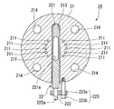
도 3, 4에 나타내는 바와 같이, 압력 조정기구(20)는, 원반 형상을 이루고 내부에 구멍부가 형성되며, 헤드밸브(121)와 공급관(30)과의 사이에 끼워져 고정되어 있다. 압력 조정기구(20)는, 원반 형상을 이루고 축방향을 따라 상류측과 하류측을 연통하는 제1 연통구멍(211) 및 제2 연통구멍(212)이 형성되는 본체부(21)와, 본체부(21)의 외주면으로 개구하여 제2 연통구멍(212)을 횡단하도록 뻗는 구멍부(213)에 배치되는 조정부(22)를 구비한다.As shown in Figs. 3 and 4, the
제1 연통구멍(211)은, 원 형상의 복수(본 실시형태에서는 10개)의 소형 구멍이며, 본체부(21)를 상류측으로부터 하류측으로 축방향으로 연통하여, 원반 형상의 본체부(21)의 중심으로부터 이간하여 동심원 형상으로 형성되어 있다. 제1 연통구멍(211)은, 복수의 원 형상의 단면적의 합계가, 그을음 블로잉 장치(10)를 구동시킬 때에 랜스관(11)을 냉각하기 위하여 필요한 증기(S)의 공급량을 확보하기 위하여, 헤드밸브(121)에서 필요한 압력을 부여 가능한 단면적의 크기로 형성되어 있다.The
제2 연통구멍(212)은, 본체부(21)를 상류측으로부터 하류측으로 축방향으로 연통하여, 원반 형상의 본체부(21)의 중심에 긴 구멍 형상으로 형성되어 있다.The
구멍부(213)는, 원반 형상의 외주면으로부터 본체부(21)를 관통하지 않도록 축방향과 직교하는 방향에 원형으로 개구하고 있으며, 제2 연통구멍(212)을 횡단하면서, 제1 연통구멍(211)은 횡단하지 않도록 형성되어 있다.The
원반 고정구멍(214)은, 본체부(21)의 외주를 따라 축방향으로 관통하는 복수의 원형 구멍이 형성되어 있다. 원반 고정구멍(214)은, 헤드밸브(121)의 플랜지부(121b)의 고정구멍과, 공급관 플랜지부(301)의 고정구멍을 연통하도록 배치되어 있으며, 볼트(50)가 삽통되어 본체부(21)를 고정하고 있다.The
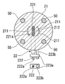
조정부(22)는, 구멍부(213)의 내부에 삽통되는 원기둥 형상의 축부재(221)와, 축부재(221)의 단부에 마련되는 조작부(222)와, 축부재(221)가 구멍부(213)로부터 빠지지 않도록 고정하는 고정부(223)를 가지고 있다.The adjusting
축부재(221)는, 원기둥 형상을 이루는 축 형상의 부재이며, 구멍부(213)보다 한 단계 작은 형상을 이룸으로써, 구멍부(213)의 중심축 둘레로 회전 가능하게 구멍부(213)의 내부에 삽통되어 있다. 축부재(221)는, 제2 연통구멍(212)과 대응하는 위치에, 축부재(221)의 축과 직교방향으로 축부재(221)를 관통하여 유통구멍(221a)이 형성되어 있다.The
유통구멍(221a)은, 제2 연통구멍(212)의 단면 형상과 동일한 크기의 긴 구멍 형상을 이루고, 축부재(221)의 축과 직교방향으로 축부재(221)를 관통하여 형성되어 있다.The flow-through
조작부(222)는, 축부재(221)의 단면으로부터, 축부재(221)보다 직경이 작은 각기둥 형상으로 돌출하여 형성되어 있으며, 축부재(221)와 접속되어 있지 않은 측의 단면에, 각인부(222a)를 가지고 있다.The operating
각인부(222a)는, 각기둥의 대각선 상에 그려진 선 형상의 각인이며, 선 형상의 각인이 뻗어 있는 방향과 축부재(221)에 형성된 유통구멍(221a)의 개구방향이 일치하도록 그려져 있다.The
조작부(222)는, 축부재(221)를 구멍부(213)에 삽통한 경우에도, 조작부(222)의 각인부(222a)측을 외부로 돌출시키도록 형성되며, 조작부(222) 자신을 공구 등에 의하여 파지하여 회전시킴으로써, 축부재(221)를 축 둘레로 회전시킨다.The operating
고정부(223)는, 축부재(221)가 관통 상태로부터 빠지지 않도록 누르는 고정판(223a)과, 고정판(223a)을 본체부(21)의 외주면에 고정하는 고정볼트(223b)를 가진다.The fixing
고정판(223a)은, 구멍부가 형성되고, 판 형상을 이루고 있으며, 조작부(222)가 구멍부에 삽통되는 구멍부 및 고정볼트(223b)가 삽통되는 구멍부가 형성되어 있다.The fixing
고정볼트(223b)는, 공지의 볼트가 사용되면 된다.As the fixing
고정부(223)는, 고정판(223a)의 구멍부에 조작부(222)를 삽통시켜, 고정볼트(223b)에 의하여 본체부(21)의 외주에 고정함으로써, 축부재(221)를 구멍부(213)로부터 빠지지 않도록 고정하고 있다.The fixing
다음으로, 상기 구성의 압력 조정기구(20)를 구비하는 그을음 블로잉 시스템(1)의 작용에 대하여 설명한다.Next, the operation of the
그을음 블로잉 장치(10)를 운전하는 경우에는, 모터(130)를 구동시켜 회전 및 이동을 개시시킴과 함께, 헤드밸브(121)의 밸브 구조를 개방시킨다. 이로써, 랜스관(11)의 노즐(110)로부터 증기(S)가 분사되면서, 랜스관(11)이 회전하고, 또한 랜스관(11)의 축방향으로 진행함으로써, 연소실(6) 내의 전열관에 부착된 퇴적물을 제거한다.When the
구체적으로는, 모터(130)가 회전을 개시하면, 트래블링 캐리지(131)의 입력축으로 회전이 전동되어, 트래블링 캐리지(131) 내의 기어로 전달된다. 트래블링 캐리지(131) 내에서 전동된 회전이, 제1 기어에 의하여 회전 속도를 변경하여 랜스관(11)으로 전달됨으로써, 랜스관(11)을 회전시킨다. 또, 트래블링 캐리지(131) 내로 전동된 회전은, 제2 기어에 의하여 입력축과 직교방향을 이루는 축의 회전으로 변환되어 출력축으로 전동된다. 트래블링 캐리지(131)의 출력축은, 하우징(14)에 마련된 래크(132)와 끼워 맞춰져 회전함으로써, 트래블링 캐리지(131)를 랜스관(11)째로 랜스관(11)의 축방향으로 진행시키고, 랜스관(11)은 하우징(14)으로부터 빠져 나와, 연소실(6) 내로 진입한다.Specifically, when the
한편, 헤드밸브(121)의 밸브 구조를 개방함으로써, 압력 조정기구(20)를 통하여 공급관(30)으로부터 공급된 증기(S)를, 피드파이프(12) 내로 유입시킨다. 피드파이프(12)에 유입하는 증기(S)는, 랜스관(11) 내로 진입하여 랜스관(11) 내에서 랜스관(11)의 축방향으로 진행한다. 랜스관(11)의 노즐(110)까지 도달한 증기(S)는, 노즐(110)로부터 분사된다.On the other hand, by opening the valve structure of the
여기에서, 압력 조정기구(20)는, 도 4에 나타내는 바와 같이, 외부로부터 조작부(222)를 회전시킴으로써, 본체부(21)의 구멍부(213)에 삽입된 축부재(221)를 회전하여 제2 연통구멍(212)이 개방되는 단면적을 조정하고, 헤드밸브(121)로 공급되는 증기(S)의 공급량을 조정한다. 다만, 헤드밸브(121) 내에 대한 증기(S)의 공급량을 조정하면, 랜스관(11) 내의 증기(S)의 공급량도 조정되기 때문에, 노즐(110)로부터 분사되는 증기(S)의 분사 압력도 조정되게 된다.4, the
또, 그을음 블로잉 장치(10)를 정지하는 경우에는, 모터(130)를 역회전시킴으로써 전동되는 회전을 역회전으로 변경한다. 이로써, 출력축이 역회전하고, 랜스관(11)이 랜스관(11)의 축방향을 후퇴하여 하우징(14) 내에 수용된다.When the
그 후, 헤드밸브(121)의 밸브 구조를 폐쇄하여 증기(S)의 공급을 정지함으로써, 피드파이프(12)에 대한 증기(S)의 유입이 멈춰, 랜스관(11)의 노즐(110)로부터의 증기(S)의 분사가 정지한다.The supply of the steam S to the
다음으로, 압력 조정기구(20)에 의하여 헤드밸브(121)에 대한 세정용 유체인 증기(S)의 공급량을 조정하는 방법의 상세에 대하여 구체적으로 도 5a부터 도 5c를 참조하여 설명한다.Next, the method of adjusting the supply amount of the steam S as the cleaning fluid to the
도 5a에 나타내는 바와 같이, 조작부(222)를 회전시켜 조정부(22)인 축부재(221)의 방향을 조정하고, 축부재(221)에 마련된 유통구멍(221a)의 개구방향과, 본체부(21)의 제2 연통구멍(212)의 개구방향을 평행으로 하여 일치시킨다. 유통구멍(221a)의 개구방향은, 조작부(222)의 단면에 마련된 각인부(222a)의 라인과 일치하고 있기 때문에, 각인부(222a)를 확인하면서 유통구멍(221a)의 개구방향을 확인한다. 유통구멍(221a)은 제2 연통구멍(212)과 단면 형상이 동일한 크기이기 때문에, 개구방향이 일치하면 제2 연통구멍(212)이 완전히 개방된 상태가 되고, 제1 연통구멍(211)으로부터 공급되는 증기(S)와 합쳐져, 헤드밸브(121)에 공급되는 증기(S)의 공급량은 최대가 된다.5A, the direction of the
도 5b에 나타내는 바와 같이, 조작부(222)를 회전시켜 조정부(22)인 축부재(221)의 방향을 조정하여, 조정부(22)의 축부재(221)에 마련된 유통구멍(221a)의 개구방향과, 본체부(21)의 제2 연통구멍(212)의 개구방향이 어긋나도록 배치한다. 즉, 유통구멍(221a)의 개구방향이 제2 연통구멍(212)에 대하여 평행으로부터 직각의 범위를 향하도록 한다. 이로써, 제2 연통구멍(212)의 개구의 일부분이 축부재(221)와 겹쳐져 폐쇄되고, 다른 부분이 유통구멍(221a)과 겹쳐져 개방된 상태가 된다. 이로 인하여, 제2 연통구멍(212)을 유통하는 것이 가능한 증기(S)의 양은 감소하여, 헤드밸브(121)에 대한 증기(S)의 공급량이 감소된다.The direction of the
다만, 제1 연통구멍(211)은 항상 개방되어 있다. 이로 인하여, 제1 연통구멍(211)에는 항상 증기(S)가 유통되고 있다.However, the
또, 조작부(222)를 회전시켜 축부재(221)의 방향을 조정함으로써, 제2 연통구멍(212)과 유통구멍(221a)과의 사이에서 서로 겹쳐져 관통하는 부분의 크기를 조정할 수 있어, 헤드밸브(121)에 공급되는 증기(S)의 공급량을 조정할 수 있다. 이 때, 압력계(122)를 확인하면서 조작부(222)를 회전시킴으로써, 헤드밸브(121) 내에 대한 증기(S)의 공급량을 확인하면서 미조정할 수 있다. 즉, 제2 연통구멍(212)과 유통구멍(221a)이 겹쳐져 개구하는 부분의 크기가 변화함으로써 헤드밸브(121) 내에 공급되는 증기(S)의 공급량이 변화하고, 이에 따라 압력이 변화하기 때문에, 헤드밸브(121)에 마련된 압력계(122)에 의하여 헤드밸브(121) 내의 증기(S)의 공급량을 확인할 수 있다.By adjusting the direction of the
도 5c에 나타내는 바와 같이, 또한, 조작부(222)를 회전시켜 조정부(22)인 축부재(221)의 방향을 조정하고, 조정부(22)의 축부재(221)에 마련된 유통구멍(221a)의 개구방향과, 본체부(21)의 제2 연통구멍(212)의 개구방향이 직각을 향하도록 배치한다. 제2 연통구멍(212)은, 개구가 축부재(221)와 겹쳐져 완전히 폐쇄된 상태가 된다. 이로 인하여, 제2 연통구멍(212)으로부터 헤드밸브(121)로 증기(S)는 공급되지 않게 된다. 그러나, 제1 연통구멍(211)은 항상 개방되어 있기 때문에, 완전히 증기(S)의 공급이 차단되지는 않고 제1 연통구멍(211)의 단면적에 따라 최소한으로 필요한 양의 증기(S)가 공급된다.The direction of the
상기와 같은 압력 조정기구(20)에 의하면, 제1 연통구멍(211)이 항상 그을음 블로잉 장치(10)를 구동시킬 때에 랜스관(11)을 냉각하기 위하여 필요한 증기(S)의 유량을 확보할 수 있도록, 헤드밸브(121)에서 필요한 공급 압력을 부여 가능한 단면적을 개구하고 있는 것에 의하여, 공급계통인 유통계통의 하류측의 랜스관(11)에 필요한 양의 증기(S)를 공급할 수 있다. 또한, 조정부(22)에 의하여 제2 연통구멍(212)의 개구되어 있는 크기를 조정하여, 단면적을 조정 가능하게 함으로써, 랜스관(11)에 공급하는 증기(S)의 공급량을 조정할 수 있다. 이로써, 유체인 증기(S)의 필요한 공급량을 확보하면서, 용이하게 유체인 증기(S)의 공급량을 조정하는 것이 가능해진다.According to the above-described
또, 압력 조정기구(20)가 원반 형상을 이룸으로써, 압력 조정기구(20)를 헤드밸브(121)와 공급관(30)과의 유통계통에 있어서의 유체를 유통시키는 방향의 약간의 스페이스에 배치할 수 있다. 이로 인하여, 헤드밸브(121)와 공급관(30)과의 사이와 같은 약간의 스페이스에도 마련할 수 있어, 기존의 설비에 대하여 큰 개조를 하지 않고 압력 조정기구(20)를 장착하는 것이 가능해진다.The
또한, 조정부(22)가, 원반 형상을 이루는 본체부(21)의 구멍부(213)를 통하여 외주면으로부터 제2 연통구멍(212)이 개구되어 있는 크기를 조정할 수 있는 것에 의하여, 증기(S)가 유통하는 개구의 단면적이 상이한 오리피스를 교환함으로써 증기(S)의 공급량을 조정하는 등의 번잡한 작업이 불필요해진다. 이로써, 보다 용이하게 유체인 증기(S)의 공급량을 조정하는 것이 가능해진다.The
또, 조작부(222)에 의하여 축부재(221)를 회전시킴으로써, 제2 연통구멍(212)을 개구시키거나 폐구시키거나 하여 개구하는 단면적을 용이하게 조정할 수 있다. 압력 조정기구(20)의 본체부(21)의 외부에 배치된 조작부(222)를 회전시키는 것만으로 증기(S)의 공급량을 조정할 수 있기 때문에, 헤드밸브(121)에 마련된 압력계(122)를 확인하면서, 공급량을 직접 미조정하는 것을 용이하게 할 수 있다. 이로써, 더욱 용이하게 유체인 증기(S)의 공급량을 조정할 수 있다.Further, by rotating the
또한, 특허문헌 1에 기재된 바와 같은 종래의 스로틀장치는, 증기(S)가 통과 가능한 유로 단면의 면적의 미조정이 어려워, 그을음 블로잉 장치(10)의 운전 상황을 확인하면서 운전 중에 공급하는 증기(S)의 공급량을 미조정하는 것이 어렵다. 그러나, 본 실시형태의 압력 조정장치(20)를 이용함으로써, 그을음 블로잉 장치(10)의 운전 중인 헤드밸브(121)의 밸브 구조를 개방한 후에, 헤드밸브(121)의 밸브 구조와는 별도로 증기(S)의 공급량을 미조정할 수 있게 된다. 이로써, 그을음 블로잉 장치(10)의 운전 상황을 확인하면서 랜스관(11)에 적절한 양의 증기(S)를 공급하는 것이 가능해진다.In the conventional throttle device as described in
또, 그을음 블로잉 장치(10)에서는, 랜스관(11)에 공급되는 증기(S)는, 전열관의 퇴적물을 제거할 뿐만 아니라, 고온의 연소실(6)에 랜스관(11)이 침입했을 때에 랜스관(11)을 냉각하여 열에 의한 손상을 방지하는 기능도 가지고 있다. 이로 인하여, 압력 조정 미스에 의하여 그을음 블로잉 장치(10)의 운전 시에 냉각에 필요한 양의 증기(S)가 랜스관(11)에 공급되지 않으면, 랜스관(11)은 냉각에 필요한 양의 증기(S)가 공급되지 않은 채 고온의 연소실(6)에 침입하여 버려, 냉각되지 않고 열에 의하여 손상될 우려가 있다. 그러나, 그을음 블로잉 장치(10)의 랜스관(11)으로 증기(S)를 공급하는 공급계통에 본 실시형태의 압력 조정기구(20)가 마련됨으로써, 랜스관(11)에는 제1 연통구멍(211)으로부터 랜스관(11)을 냉각하기 위하여 필요한 양의 증기(S)를 공급할 수 있다. 이로써, 오작동시켜 의도치 않게 제2 연통구멍(212)을 폐구시켜 버렸다고 해도, 랜스관(11)이 연소실(6) 내에 침입하여 열에 의하여 손상되는 것을 방지하는 것이 가능해진다.In addition, in the
또한, 그을음 블로잉 장치(10)의 공급계통의 단부인 헤드밸브(121)와, 증기(S)를 공급하는 배관인 공급관(30)과의 사이에 압력 조정기구(20)가 마련됨으로써, 그을음 블로잉 장치(10) 자체는 개조를 할 필요가 없기 때문에, 기설의 그을음 블로잉 장치(10)에 대하여, 사후적으로 용이하게 압력 조정기구(20)를 설치할 수 있다.The
또, 이와 같은 압력 조정기구(20)를 그을음 블로잉 장치(10)에 이용함으로써, 전열관이 크게 오염되지 않고 퇴적물이 거의 부착되어 있지 않은 경우에, 제2 연통구멍(212)의 단면적을 작게 조정하여, 헤드밸브(121)에 대한 증기(S)의 공급량을 감소시키면, 랜스관(11) 내의 증기(S)량이 감소되고, 노즐(110)로부터의 분사 압력이 저하하여, 제거 대상인 전열관에 과도한 압력을 주지 않고 손상을 방지할 수 있다. 이로써 제거 대상이 되는 전열관 등의 수명의 장기화를 도모할 수 있다.By using such a
또한, 반대로 전열관이 크게 오염되어 있고 퇴적물이 대량으로 부착되어 있는 경우에는, 제2 연통구멍(212)의 단면적을 크게 조정하여, 헤드밸브(121)에 대한 증기(S)의 공급량을 증가시키면, 노즐(110)로부터의 분사 압력이 증가되어, 퇴적물의 제거 성능을 향상시킬 수 있다. 이로써, 효율적으로 퇴적물을 제거하는 것이 가능해진다.On the contrary, when the heat transfer pipe is largely contaminated and a large amount of deposit is deposited, if the cross-sectional area of the
이상, 본 발명의 실시형태에 대하여 도면을 참조하여 상세하게 설명했지만, 각 실시형태에 있어서의 각 구성 및 그들의 조합 등은 일례이며, 본 발명의 취지로부터 일탈하지 않는 범위 내에서, 구성의 부가, 생략, 치환, 및 그 외의 변경이 가능하다. 또, 본 발명은 실시형태에 의하여 한정되지 않으며, 클레임의 범위에 의해서만 한정된다.Although the embodiments of the present invention have been described in detail with reference to the drawings, the respective constitutions and combinations thereof in the embodiments are merely examples, and the addition of the constituent elements, Omission, substitution, and other modifications are possible. The present invention is not limited to the embodiments but is limited only by the scope of claims.
또, 압력 조정기구(20)는, 본 실시형태와 같이 헤드밸브(121)와 공급관(30)과의 사이에 마련되어 있을 필요는 없고, 유체인 증기(S)의 유통경로에 마련되어 있으면 되며, 예를 들면, 헤드밸브 본체(121a)에 마련되어 있어도 된다.The
또한, 본 실시형태의 그을음 블로잉 시스템(1)의 그을음 블로잉 장치(10)에 이용되는 것에 한정되는 것은 아니며, 예를 들면, 정치(定置) 회전형의 그을음 블로잉 장치나 디슬래거형의 그을음 블로잉 장치를 이용해도 된다.The present invention is not limited to the
또, 제1 연통구멍(211) 및 제2 연통구멍(212)의 형상은 본 실시형태에 한정되는 것은 아니며, 예를 들면, 원 형상의 구멍부로 각각 형성해도 된다.In addition, the shapes of the
또한, 조정부(22)의 축부재(221)의 폭보다 큰 하나의 구멍부을 형성하여, 조정부(22)에 의하여 막혀 있지 않은 부분을 제1 연통구멍(211)으로 하고, 유통구멍(221a) 자체를 제2 연통구멍(212)으로 해도 된다.One hole larger than the width of the
또, 본 발명에 관한 압력 조정기구(20)는, 그을음 블로잉 장치(10)에 이용되는 것에 한정되는 것은 아니며, 하류측에 최소한으로 필요한 압력을 부여하여 유체를 공급하는 유통계통에 이용되면 된다.The
또한, 유통구멍(221a)의 단면 형상은 제2 연통구멍(212)의 단면 형상과 동일한 크기인 것에 한정되는 것은 아니며, 예를 들면, 유통구멍(221a)의 단면 형상이 커도 되고, 반대로 작아도 된다. 즉, 사용하는 장치에 따라, 유체인 증기(S)를 최소한으로 필요한 공급량에 따라 적절히 변경하면 된다.The cross-sectional shape of the flow-through
또, 공급부(120)는, 본 실시형태와 같이 독립적으로 개방 또는 폐쇄하는 구조인 것에 한정되지 않으며, 예를 들면, 헤드밸브(121)의 밸브 구조를 랜스관(11)의 진행 및 개방과 연동시켜 개방 또는 폐쇄시키는 개폐장치를 가지는 것으로 하여, 랜스관(11)의 움직임에 맞추어 자동적으로 개방 또는 폐쇄하는 구조로 해도 된다.For example, the valve mechanism of the
본 발명은, 압력 조정기구 및 압력 조정기구를 구비한 그을음 블로잉 시스템에 관한 것이다. 본 발명의 압력 조정장치에 의하면, 제1 연통구멍에 의하여 최소한으로 필요한 유체의 공급량을 확보하면서, 제2 연통구멍에 의하여 용이하게 유체의 공급량을 조정하는 것이 가능해진다.The present invention relates to a soot blowing system provided with a pressure adjusting mechanism and a pressure adjusting mechanism. According to the pressure adjusting device of the present invention, it is possible to easily adjust the supply amount of the fluid by the second communication hole while securing the supply amount of the minimum required fluid by the first communication hole.
1 그을음 블로잉 시스템
10 그을음 블로잉 장치
11 랜스관
110 노즐
12 피드파이프
120 밸브부
121 헤드밸브
121a 헤드밸브 본체
121b 플랜지부
122 압력계
13 구동부
130 모터
131 트래블링 캐리지
132 래크
14 하우징
20 압력 조정기구
21 본체부
211 제1 연통구멍
212 제2 연통구멍
213 구멍부
214 원반 고정구멍
22 조정부
221 축부재
221a 유통구멍
222 조작부
222a 각인부
223 고정부
223a 고정판
223b 고정부 볼트
50 볼트
51 너트
30 공급관
301 공급관 플랜지부
6 연소실1 Soot Blowing System
10 Soot blowing device
11 Lance Hall
110 nozzle
12 feed pipes
120 valve portion
121 head valve
121a head valve body
121b flange portion
122 pressure gauge
13 driver
130 motor
131 Traveling carriage
132 Racks
14 Housing
20 Pressure adjusting mechanism
21 body portion
211 first communication hole
212 Second communicating hole
213 hole
214 Disk fixing hole
22 adjuster
221 shaft member
221a distribution hole
222 Control unit
222a imprint
223 Fixed portion
223a fixed plate
223b fastening bolt
50 volts
51 nut
30 suppliers
301 Supply pipe flange
6 combustion chamber
Claims (4)
상기 세정용 유체의 공급원과 접속되는 공급관과,
상기 세정용 유체의 유통계통에 마련되어, 상기 세정용 유체의 압력을 조정하고, 상기 공급관과 상기 헤드밸브와의 사이에 마련된 압력 조정 기구를 구비하고,
상기 헤드밸브는, 원통 형상을 이루는 헤드밸브 본체와, 상기 헤드밸브 본체의 외주에 링 형상으로 돌출하여 형성되는 플랜지부를 갖고,
상기 공급관은, 상기 헤드밸브측의 단부의 외주에 링 형상으로 돌출하여 형성되는 공급관 플랜지부를 갖고,
상기 압력 조정 기구는, 상기 플랜지부와 상기 공급관 플랜지부에 끼워 넣어져서 상기 그을음 블로잉 장치에 고정되고,
상기 헤드밸브는,
원통 형상을 이루는 헤드밸브 본체와, 상기 헤드밸브 본체 내의 상기 세정용 유체의 압력을 측정하여 표시하는 압력계를 갖고,
상기 압력 조정 기구는,
상기 유통계통의 상류측과 하류측을 연통함과 함께, 상기 하류측에서 최소한으로 필요한 압력을 부여시키는 단면적을 가지는 제1 연통구멍과, 상기 유통계통의 상류측과 하류측을 연통하는 제2 연통구멍이 형성되는 본체부와,
상기 제2 연통구멍의 단면적을 조정 가능한 조정부를 구비하는 것을 특징으로 하는 그을음 블로잉 시스템.A soot blowing device having a lance pipe for spraying a cleaning fluid and a head valve for starting and stopping supply of the cleaning fluid as a supply part for supplying the cleaning fluid to the lance pipe;
A supply pipe connected to a supply source of the cleaning fluid,
And a pressure adjusting mechanism provided in the circulation system of the cleaning fluid for adjusting the pressure of the cleaning fluid and provided between the supply pipe and the head valve,
Wherein the head valve includes a head valve body having a cylindrical shape and a flange portion protruding in a ring shape on an outer periphery of the head valve body,
Wherein the supply pipe has a supply pipe flange portion protruding in a ring shape on an outer periphery of an end portion on the head valve side,
Wherein the pressure adjusting mechanism is fitted to the flange portion and the supply pipe flange portion and is fixed to the soot blowing device,
Wherein the head valve includes:
And a pressure gauge for measuring and displaying the pressure of the cleaning fluid in the head valve body,
The pressure adjusting mechanism includes:
A first communication hole communicating an upstream side and a downstream side of the distribution system and having a cross sectional area for giving a minimum necessary pressure at the downstream side; and a second communication hole communicating an upstream side and a downstream side of the distribution system, A body portion in which a hole is formed,
And an adjusting section capable of adjusting a cross-sectional area of the second communication hole.
상기 본체부는,
원반 형상을 이루고, 축방향을 따라 상기 제1 연통구멍 및 상기 제2 연통구멍이 형성됨과 함께, 외주면으로 개구하여 상기 제2 연통구멍을 횡단하도록 뻗는 구멍부가 형성되며,
상기 조정부는, 상기 구멍부를 통하여 상기 본체부의 외주면측으로부터 조정 가능한 것을 특징으로 하는 그을음 블로잉 시스템.The method according to claim 1,
Wherein,
Wherein the first communication hole and the second communication hole are formed along the axial direction and an opening portion opening to the outer peripheral surface and extending across the second communication hole is formed,
Wherein the adjusting portion is adjustable from an outer peripheral surface side of the main body through the hole portion.
상기 조정부는,
축 형상으로 형성되고, 상기 구멍부에 자신의 중심축 둘레로 회전 가능하게 삽입되며, 상기 중심축과 직교하는 방향으로 관통하는 유통구멍이 형성된 축부재와,
상기 축부재에 마련되어, 상기 축부재를 축 둘레로 회전시키는 조작부를 구비하는 것을 특징으로 하는 그을음 블로잉 시스템.The method of claim 2,
Wherein,
A shaft member which is formed in an axial shape and which is inserted into the hole portion so as to be rotatable about its own central axis and in which a flow hole penetrating in a direction perpendicular to the central axis is formed,
And an operating portion provided on the shaft member for rotating the shaft member about an axis.
상기 유통계통은, 그을음 블로잉 장치의 랜스관으로 세정용 유체를 공급하는 공급계통이고,
상기 제1 연통구멍의 단면적은, 상기 랜스관을 냉각하기 위하여 필요한 상기 세정용 유체의 유량을 확보하기 위한 최소한으로 필요한 압력을 부여 가능하게 설정되어 있는 것을 특징으로 하는 그을음 블로잉 시스템.
The method according to any one of claims 1 to 3,
The distribution system is a supply system for supplying the cleaning fluid to the lance pipe of the soot blowing apparatus,
Wherein the cross-sectional area of the first communication hole is set so as to give a minimum necessary pressure for securing the flow rate of the cleaning fluid necessary for cooling the lance pipe.
Applications Claiming Priority (1)
| Application Number | Priority Date | Filing Date | Title |
|---|---|---|---|
| PCT/JP2012/082933 WO2014097426A1 (en) | 2012-12-19 | 2012-12-19 | Pressure-adjusting mechanism and soot-blowing system having same |
Related Parent Applications (1)
| Application Number | Title | Priority Date | Filing Date |
|---|---|---|---|
| KR1020157016103A Division KR20150086341A (en) | 2012-12-19 | 2012-12-19 | Pressure-adjusting mechanism and soot-blowing system having same |
Publications (2)
| Publication Number | Publication Date |
|---|---|
| KR20170018109A true KR20170018109A (en) | 2017-02-15 |
| KR101813455B1 KR101813455B1 (en) | 2017-12-28 |
Family
ID=50977809
Family Applications (2)
| Application Number | Title | Priority Date | Filing Date |
|---|---|---|---|
| KR1020157016103A KR20150086341A (en) | 2012-12-19 | 2012-12-19 | Pressure-adjusting mechanism and soot-blowing system having same |
| KR1020177003402A KR101813455B1 (en) | 2012-12-19 | 2012-12-19 | Soot-blowing system |
Family Applications Before (1)
| Application Number | Title | Priority Date | Filing Date |
|---|---|---|---|
| KR1020157016103A KR20150086341A (en) | 2012-12-19 | 2012-12-19 | Pressure-adjusting mechanism and soot-blowing system having same |
Country Status (4)
| Country | Link |
|---|---|
| JP (1) | JP6111269B2 (en) |
| KR (2) | KR20150086341A (en) |
| IN (1) | IN2015DN04291A (en) |
| WO (1) | WO2014097426A1 (en) |
Families Citing this family (1)
| Publication number | Priority date | Publication date | Assignee | Title |
|---|---|---|---|---|
| DK180366B1 (en) * | 2019-10-04 | 2021-02-08 | Degn Design Aps | Method and apparatus for cleaning boiler surfaces in an incineration plant |
Citations (1)
| Publication number | Priority date | Publication date | Assignee | Title |
|---|---|---|---|---|
| JPH02287009A (en) | 1989-04-01 | 1990-11-27 | Bergemann Gmbh | Soot blower |
Family Cites Families (6)
| Publication number | Priority date | Publication date | Assignee | Title |
|---|---|---|---|---|
| JPS63225770A (en) * | 1987-03-16 | 1988-09-20 | Toshiba Corp | Exhaust regulation valve |
| JP2827599B2 (en) * | 1991-07-25 | 1998-11-25 | 富士電機株式会社 | Variable throttle valve |
| US5237718A (en) * | 1992-05-01 | 1993-08-24 | The Babcock & Wilcox Company | Sootblower with lance bypass flow |
| JPH06201119A (en) * | 1992-12-28 | 1994-07-19 | Mitsubishi Heavy Ind Ltd | Jet medium flow rate control method of soot blower |
| JPH06249421A (en) * | 1993-02-26 | 1994-09-06 | Mitsubishi Heavy Ind Ltd | Soot-blower |
| JP2010156522A (en) * | 2009-01-05 | 2010-07-15 | Ihi Corp | Ash removing method for heat exchanger and soot blower |
-
2012
- 2012-12-19 JP JP2014552816A patent/JP6111269B2/en active Active
- 2012-12-19 IN IN4291DEN2015 patent/IN2015DN04291A/en unknown
- 2012-12-19 WO PCT/JP2012/082933 patent/WO2014097426A1/en active Application Filing
- 2012-12-19 KR KR1020157016103A patent/KR20150086341A/en active Application Filing
- 2012-12-19 KR KR1020177003402A patent/KR101813455B1/en active IP Right Grant
Patent Citations (1)
| Publication number | Priority date | Publication date | Assignee | Title |
|---|---|---|---|---|
| JPH02287009A (en) | 1989-04-01 | 1990-11-27 | Bergemann Gmbh | Soot blower |
Also Published As
| Publication number | Publication date |
|---|---|
| KR20150086341A (en) | 2015-07-27 |
| JPWO2014097426A1 (en) | 2017-01-12 |
| IN2015DN04291A (en) | 2015-10-16 |
| KR101813455B1 (en) | 2017-12-28 |
| JP6111269B2 (en) | 2017-04-05 |
| WO2014097426A1 (en) | 2014-06-26 |
Similar Documents
| Publication | Publication Date | Title |
|---|---|---|
| JP4729042B2 (en) | Purification equipment for gas turbines | |
| US6892679B2 (en) | Multi-media rotating sootblower and automatic industrial boiler cleaning system | |
| CA2150759C (en) | Convertible media sootblower lance tube | |
| CN100522485C (en) | Abrasive cutting device | |
| CA2094999C (en) | Sootblower with lance bypass flow | |
| EP2401553B1 (en) | Retractable articulating robotic sootblower | |
| KR101813455B1 (en) | Soot-blowing system | |
| US20200284158A1 (en) | Device for cleaning turbine blades of a jet engine | |
| DK2780632T3 (en) | INJECTION COOLER | |
| EP1979701B1 (en) | Device with fluid distributor and measured value recording and method for operating of a boiler | |
| US6782902B2 (en) | Sootblower lance tube for dual cleaning media | |
| TW201703865A (en) | Jet cartridges for jetting fluid material, and related methods | |
| JP4906352B2 (en) | Soot blower equipment | |
| KR20050107302A (en) | Fuel saving apparatus for an automobile | |
| EP2336704B1 (en) | Sootblower with progressive cleaning arc | |
| KR101809915B1 (en) | Hydraulic oil cooling apparatus for vibrator | |
| SE534199C2 (en) | A mix-safe valve comprising a cleaning device and a cleaning arrangement for cleaning a valve outlet space | |
| JP6175324B2 (en) | Clinker removal device | |
| KR102205726B1 (en) | Spindle assembly and machining center comprising the same | |
| KR20100115021A (en) | Vane of variable nozzle apparatus | |
| KR20130097016A (en) | Spindle apparatus | |
| JP2002162019A (en) | Stationary rotating soot blow-off apparatus | |
| JP6668000B2 (en) | Machining center | |
| JPH08145329A (en) | Clinker removing device | |
| KR200314714Y1 (en) | The Desuperheater of Distillate Plant |
Legal Events
| Date | Code | Title | Description |
|---|---|---|---|
| A107 | Divisional application of patent | ||
| A201 | Request for examination | ||
| E902 | Notification of reason for refusal | ||
| AMND | Amendment | ||
| E601 | Decision to refuse application | ||
| AMND | Amendment | ||
| X701 | Decision to grant (after re-examination) | ||
| GRNT | Written decision to grant |