KR20170012142A - Radioelectric device for transmitting and receiving radioelectric waves and associated radio altimetry system - Google Patents
Radioelectric device for transmitting and receiving radioelectric waves and associated radio altimetry system Download PDFInfo
- Publication number
- KR20170012142A KR20170012142A KR1020160093689A KR20160093689A KR20170012142A KR 20170012142 A KR20170012142 A KR 20170012142A KR 1020160093689 A KR1020160093689 A KR 1020160093689A KR 20160093689 A KR20160093689 A KR 20160093689A KR 20170012142 A KR20170012142 A KR 20170012142A
- Authority
- KR
- South Korea
- Prior art keywords
- antenna aperture
- aperture value
- radiating elements
- arrays
- radio wave
- Prior art date
Links
- 238000003491 array Methods 0.000 claims abstract description 36
- 230000004913 activation Effects 0.000 claims abstract description 28
- 230000003213 activating effect Effects 0.000 claims abstract description 9
- 238000000034 method Methods 0.000 claims description 21
- 230000005540 biological transmission Effects 0.000 claims description 15
- 230000009849 deactivation Effects 0.000 claims description 14
- 239000011159 matrix material Substances 0.000 claims description 6
- 238000012545 processing Methods 0.000 claims description 5
- 230000006870 function Effects 0.000 claims description 4
- 230000004048 modification Effects 0.000 abstract 1
- 238000012986 modification Methods 0.000 abstract 1
- 230000004044 response Effects 0.000 description 4
- 238000004891 communication Methods 0.000 description 2
- 238000004519 manufacturing process Methods 0.000 description 2
- 230000005855 radiation Effects 0.000 description 2
- 238000001228 spectrum Methods 0.000 description 2
- 230000017105 transposition Effects 0.000 description 2
- RZVHIXYEVGDQDX-UHFFFAOYSA-N 9,10-anthraquinone Chemical compound C1=CC=C2C(=O)C3=CC=CC=C3C(=O)C2=C1 RZVHIXYEVGDQDX-UHFFFAOYSA-N 0.000 description 1
- 238000012951 Remeasurement Methods 0.000 description 1
- 238000013459 approach Methods 0.000 description 1
- 230000000694 effects Effects 0.000 description 1
- 238000005305 interferometry Methods 0.000 description 1
- 238000005259 measurement Methods 0.000 description 1
- 238000012795 verification Methods 0.000 description 1
Images


Classifications
-
- G—PHYSICS
- G01—MEASURING; TESTING
- G01S—RADIO DIRECTION-FINDING; RADIO NAVIGATION; DETERMINING DISTANCE OR VELOCITY BY USE OF RADIO WAVES; LOCATING OR PRESENCE-DETECTING BY USE OF THE REFLECTION OR RERADIATION OF RADIO WAVES; ANALOGOUS ARRANGEMENTS USING OTHER WAVES
- G01S13/00—Systems using the reflection or reradiation of radio waves, e.g. radar systems; Analogous systems using reflection or reradiation of waves whose nature or wavelength is irrelevant or unspecified
- G01S13/88—Radar or analogous systems specially adapted for specific applications
- G01S13/882—Radar or analogous systems specially adapted for specific applications for altimeters
-
- G—PHYSICS
- G01—MEASURING; TESTING
- G01S—RADIO DIRECTION-FINDING; RADIO NAVIGATION; DETERMINING DISTANCE OR VELOCITY BY USE OF RADIO WAVES; LOCATING OR PRESENCE-DETECTING BY USE OF THE REFLECTION OR RERADIATION OF RADIO WAVES; ANALOGOUS ARRANGEMENTS USING OTHER WAVES
- G01S13/00—Systems using the reflection or reradiation of radio waves, e.g. radar systems; Analogous systems using reflection or reradiation of waves whose nature or wavelength is irrelevant or unspecified
- G01S13/02—Systems using reflection of radio waves, e.g. primary radar systems; Analogous systems
- G01S13/06—Systems determining position data of a target
- G01S13/08—Systems for measuring distance only
- G01S13/32—Systems for measuring distance only using transmission of continuous waves, whether amplitude-, frequency-, or phase-modulated, or unmodulated
- G01S13/34—Systems for measuring distance only using transmission of continuous waves, whether amplitude-, frequency-, or phase-modulated, or unmodulated using transmission of continuous, frequency-modulated waves while heterodyning the received signal, or a signal derived therefrom, with a locally-generated signal related to the contemporaneously transmitted signal
- G01S13/343—Systems for measuring distance only using transmission of continuous waves, whether amplitude-, frequency-, or phase-modulated, or unmodulated using transmission of continuous, frequency-modulated waves while heterodyning the received signal, or a signal derived therefrom, with a locally-generated signal related to the contemporaneously transmitted signal using sawtooth modulation
-
- G—PHYSICS
- G01—MEASURING; TESTING
- G01S—RADIO DIRECTION-FINDING; RADIO NAVIGATION; DETERMINING DISTANCE OR VELOCITY BY USE OF RADIO WAVES; LOCATING OR PRESENCE-DETECTING BY USE OF THE REFLECTION OR RERADIATION OF RADIO WAVES; ANALOGOUS ARRANGEMENTS USING OTHER WAVES
- G01S7/00—Details of systems according to groups G01S13/00, G01S15/00, G01S17/00
- G01S7/02—Details of systems according to groups G01S13/00, G01S15/00, G01S17/00 of systems according to group G01S13/00
- G01S7/03—Details of HF subsystems specially adapted therefor, e.g. common to transmitter and receiver
- G01S7/032—Constructional details for solid-state radar subsystems
-
- H—ELECTRICITY
- H01—ELECTRIC ELEMENTS
- H01Q—ANTENNAS, i.e. RADIO AERIALS
- H01Q21/00—Antenna arrays or systems
- H01Q21/30—Combinations of separate antenna units operating in different wavebands and connected to a common feeder system
-
- H—ELECTRICITY
- H01—ELECTRIC ELEMENTS
- H01Q—ANTENNAS, i.e. RADIO AERIALS
- H01Q25/00—Antennas or antenna systems providing at least two radiating patterns
- H01Q25/002—Antennas or antenna systems providing at least two radiating patterns providing at least two patterns of different beamwidth; Variable beamwidth antennas
-
- H—ELECTRICITY
- H01—ELECTRIC ELEMENTS
- H01Q—ANTENNAS, i.e. RADIO AERIALS
- H01Q3/00—Arrangements for changing or varying the orientation or the shape of the directional pattern of the waves radiated from an antenna or antenna system
- H01Q3/01—Arrangements for changing or varying the orientation or the shape of the directional pattern of the waves radiated from an antenna or antenna system varying the shape of the antenna or antenna system
Abstract
Description
본 발명은 미리 설정된(predetermined) 변조 신호(modulation signal) 및 트랜시버 안테나 시스템(transceiver antenna system)에 의해 주파수-변조된(frequency-modulated) 전파를(radio wave) 생성하는 전파 발생기(generator)를 포함하고, 연관된 안테나 구경 각(aperture angle)을 갖는, 전파를 송신하고 수신하는 무선 전자 장치에 관련된다The present invention includes a radio wave generator that generates a radio wave by a predetermined modulation signal and a frequency-modulated by a transceiver antenna system , ≪ / RTI > with an associated antenna aperture angle, to transmit and receive radio waves
본 발명은 또한 연관된 전파 고도계 시스템(radio altimetry system)에 관련된다.The present invention also relates to an associated radio altimetry system.
본 발명은 무선통신 분야에 적용될 수 있고, 더욱 특히 항공 분야aeronautic field)에 적용될 수 있다.The present invention can be applied to the field of wireless communication and more particularly to the aeronautical field of the aeronautical field.
민간 또는 군사 항공 분야에서 사용되는 전파 고도계 시스템은, 일반적으로 전파 고도계(radio altimeters)로 언급된다.Radio altimeter systems used in civilian or military aeronautical applications are generally referred to as radio altimeters.
전파 고도계는 항공기(aircraft)상에 설치되는 기구(instrument)이고, 상기 항공기의 지면 또는 오버플로운 표면(overflown surface)에 대한 고도(height)를 제공할 수 있다. 전파 고도계는 특히 접근(approach), 착륙(landing), 및 이륙(take off)와 같은 자동 비행 페이스(automatic flight phase)나 크리티컬 비행 페이스(critical flight phase)인 동안 사용된다. 상기 전파 고도계는 특히 시계가 없는(no visibility) 상황에서 다른 TAWS(terrain awareness warning system) 또는 AFCS(automatic flight control system) 타입의 기기들, 및 최소 고도(minimum height)를 계산하기 위한 미션 컴퓨터(mission computer)와 결합하여 사용해 조종사에게 도움(assistance)을 제공하는 필수 요소(essential element)이다.A radio altimeter is an instrument mounted on an aircraft and can provide a height to the ground or overflow surface of the aircraft. The radio altimeter is used during the automatic flight phase or critical flight phase, especially for approach, landing, and take off. The abovementioned radio altimeter is particularly suitable for use with other types of terrain awareness warning system (TAWS) or automatic flight control system (AFCS) type devices, and a mission computer for calculating minimum heights, computer) to provide assistance to the pilot.
상기 전파 고도계에 의해 제공되는 상기 고도 측정(the height measurement)은 또한 상기 탑재된 컴퓨터(onboard computer)에 의해 수행되는 다양한 컴퓨터적 응용(computational applications)에, 예를 들어 오버플로운 지형(overflown terrain)의 미리 설립된 지도(preestablished map)에 관해 상기 항공기의 위치를 재측정에, 사용될 수 있다.The height measurement provided by the radio altimeter may also be used in various computational applications performed by the onboard computer, for example overflow terrain Can be used to re-measure the position of the aircraft relative to a pre-established map.
최신식의(in the state of the art), 다른 타입의 전파 고도계가 알려져 있는데, 이와 같은 기구들(instruments)의 일반적인 원칙(general principle)은, 전송되어 상기 지면으로부터 반사된 후에 수신되는 무선 신호(radio signal)의 전파 시간(propagation time)을 측정함으로써 상기 고도를 측정하는 것이다.Other types of radio altimeters are known in the state of the art, and the general principle of such instruments is that the radio signals transmitted after being reflected from the ground, the propagation time of the signal is measured to measure the altitude.
전파 고도계는 미리 설정된(predetermined) 변조 신호(modulation signal) 및 트랜시버 안테나 시스템(transceiver antenna system)에 의해 주파수-변조된(frequency-modulated) 전파를(radio wave) 생성하는 전파 발생기(generator)를 포함하고, 연관된 안테나 구경 각(aperture angle)을 갖는다.The radio altimeter includes a radio wave generator that generates a radio wave by a predetermined modulation signal and a frequency-modulated by a transceiver antenna system , And an associated antenna aperture angle.
주파수(frequency) 또는 기울기 스윙(slope swing) δF에 따라, 실질적으로 선형적인 기울기(substantially linear slope)와 램프(ramp)를 갖는 변조 신호에 의해 주파수-변조된 전파의 연속적인 송신(continuous transmission)을, FMCW(frequency-modulated continuous wave)로 언급되는, 사용하는 것이 알려져 있다. 민간 분야에서, 상기 사용되는 주파수 대역은 4.2GHz에서 4.4GHz이다. 상기 지면에서 반사된 후에, 반사된 전파는 항공기의 고도에 기초한 기간(duration) τ 이후에 에코(echo)로서 수신되어 상기 고도를 계산할 수 있게 된다.Continuous transmission of frequency-modulated radio waves by a modulated signal with a substantially linear slope and ramp, according to frequency or slope swing δF, , And frequency-modulated continuous wave (FMCW). In the private sector, the frequency band used is 4.2 GHz to 4.4 GHz. After being reflected from the ground, the reflected radio waves are received as an echo after a duration < RTI ID = 0.0 > tau, < / RTI >
상기 계산의 정밀성은 특히, 일반적으로는 지면인, 타게팅된 표면(targeted surface)의 상기 송신된 파(transmitted wave)의 수신 구역(reception zone)의 크기에 기초하고, 상기 수신 구역의 크기는 안테나 시스템의 구경 및 항공기의 고도(altitude)에 기초한다.The accuracy of the calculation is particularly based on the size of the reception zone of the transmitted wave of the targeted surface, which is generally the ground, And the altitude of the aircraft.
상기 사용되는 안테나 시스템이 고정된 구경을 갖고 있는 경우, 상기 수신 구역의 크기는 상기 항공기의 고도에 의해 상당히 다르다. 실제로, 상기 고도가 높을수록, 상기 수신 구역은 더 커진다.When the used antenna system has a fixed aperture, the size of the receiving area is significantly different due to the altitude of the aircraft. In fact, the higher the altitude, the larger the receiving area.
상기 수신 구역의 확장됨(enlargement)은 몇몇 문제점(drawback)을 갖는데, 특히 높이서 반사되는 요소(element)가 캐치(catch)되어 오버플로운 고도(overflown height)를 왜곡되게 계산 수 있는 가능성이 있다.The enlargement of the receiving area has some drawbacks, in particular the possibility of catching the reflected element at height and calculating the overflow height to be distorted.
게다가, 계산된 고도 정보와 연관된 방향(direction)에 관한 불확실성(uncertainty)은 추가적인 안테나를 요구하는 간섭계법 시스템의 추가 없이 전파 고도 재측정을 위한 잠재적인 에러를 야기한다.In addition, the uncertainty with respect to the direction associated with the computed altitude information causes potential errors for radio altitude remeasurement without the addition of an interferometry system requiring additional antennas.
실시예들은 전파의 송신을 컨트롤하여 정밀하게 타겟팅 할 수 있다.Embodiments can precisely target transmission by controlling transmission of radio waves.
또한, 실시예들은 안테나 시스템을 소형화하여 낮은 비용이 들게 할 수 있다.Embodiments can also make the antenna system smaller and less costly.
일 실시예에 따른 미리 설정된 변조 신호 및 트랜시버 안테나 시스템(transceiver antenna system)에 의해 주파수-변조된(frequency-modulated) 전파를(radio wave) 생성하는 전파 발생기(generator)를 포함하는 전파를 송신하고 수신하는 무선 전자 장치 -상기 무선 전자 장치는 연관된 안테나 구경 값(aperture value)과 송신-수신 각(transmission-reception angle)을 갖고, 상기 송신된 전파(said transmitted radio wave)를 송신하고 전파(a radio wave)를 수신할 수 있음- 에 있어서 상기 안테나 시스템(44)은 제1 주파수 대역(a first frequency band)으로 방사할 수 있는 방사 소자(radiating elements; 50a, 50b, 50c, 50d)의 제1 어레이(a first array; 45), 및 제2 주파수 대역(a second frequency band)으로 방사할 수 있는 방사 소자의 적어도 하나의 제2 어레이(second array; 52i, 55, 56)와 상기 방사 소자의 제1 어레이 및 제2 어레이 각각을 활성화 및/또는 비활성화할 수 있는 복수의 활성화 소자(activation elements; 701, ..., 70i, ..., 70n)와 선택된 안테나 구경 값에 기초하여 상기 활성화 소자(701, ..., 70i, ..., 70n)를 제어할 수 있는 컨트롤 모듈(a control module; 42)을 포함할 수 있다.Transmitting and receiving a radio wave including a radio wave generator that generates a radio wave by a predetermined modulation signal and a transceiver antenna system according to an exemplary embodiment of the present invention. The wireless electronic device having an associated antenna aperture value and a transmission-reception angle, the method comprising transmitting said transmitted radio wave and transmitting said radio wave The
상기 무선 전자 장치는 선택된 안테나 구경 값을 획득하는 모듈(36)을 포함하는 특징이 있을 수 있다.The wireless electronic device may be characterized in that it includes a
상기 안테나 시스템은 방사 소자의 제2 어레이의 행렬(matrix; 55)에 배열된 방사 소자의 복수의 제2 어레이(521, ..., 52i, ..., 52n)를 포함하고 방사 소자의 제2 어레이 각각은 고유의 전력 공급점(power supply point)을 갖는 특징이 있을 수 있다.The antenna system includes a plurality of second arrays of radiating elements (52 1 , ..., 52 i , ..., 52 n ) arranged in a matrix of a second array of radiating elements, Each of the second arrays of elements may be characterized by a unique power supply point.
상기 활성화 소자(701, ..., 70i, ..., 70n)는 스위치고 상기 장치는 상기 방사 소자의 제1 및 제2 어레이의 복수의 활성화/비활성화 구성(configurations)을 생성하기 위해 배열된 복수의 스위치를 포함하는 특징이 있을 수 있다.The activation elements 70 1 , ..., 70 i , ..., 70 n are switches and the device generates a plurality of activation / deactivation configurations of the first and second arrays of radiating elements And may include a plurality of switches arranged for switching.
상기 안테나 구경 값은 안테나 구경 값들의 이산 집합(discrete set) 중에서 선택되고, 상기 이산 집합의 안테나 구경 값 각각은 상기 방사 소자의 제1 및 제2 어레이의 활성화/비활성화 구성에 대응되는 특징이 있을 수 있다.Wherein the antenna aperture value is selected from a discrete set of antenna aperture values and each antenna aperture value of the discrete set may be characterized by an activation / deactivation configuration of the first and second arrays of radiating elements have.
상기 무선 전자 장치는 메모리 모듈(34)를 포함하고, 상기 안테나 구경 값들의 이산 집합 및 안테나 구경 값 각각을 위한 방사 소자의 상기 제1 및 제2 어레이의 연관된 활성화/비활성화 구성은 저장되는 특징이 있을 수 있다.The wireless electronic device includes a memory module (34), wherein the associated activated / deactivated configuration of the first and second arrays of radiating elements for each of a discrete set of antenna aperture values and an antenna aperture value .
일 실시예에 따른 전파를 송신-수신하기 위한 무선 전자 장치에 의해 수행되는, 전파를 송신-수신하는 방법의 송신 또는 수신 모드는 선택된 안테나 구경 값을 획득하는 단계(80)와 상기 선택된 구경 값에 기초하여 상기 방사 소자의 제1 및 제2 어레이의 복수의 활성화/비활성화 소자를 제어하는 단계(88, 90)를 포함하는 특징이 있을 수 있다.The transmission or reception mode of the method of transmitting and receiving radio waves, performed by a wireless electronic device for transmitting and receiving radio waves according to an embodiment, includes the steps of obtaining (80) a selected antenna aperture value and And controlling (88, 90) a plurality of activation / deactivation elements of the first and second arrays of the radiating elements based on the control signal.
상기 송신 모드는 제1 주파수 대역의 미리 설정된 변조 신호에 의해 주파수-변조된 적어도 하나의 전파를 생성하는 단계(82)를 더 포함할 수 있다.The transmission mode may further comprise generating (82) at least one radio wave frequency-modulated by a predetermined modulation signal of the first frequency band.
상기 방법의 방출 모드(emission mode)는 상기 선택된 안테나 구경 값을 안테나 구경 값의 최대값과 비교하는 단계(84)와 상기 비교가 부정적(negative)인 경우, 상기 생성된 전파를 제2 주파수 대역으로 바꾸는(transpose) 단계(86)를 포함하는 특징이 있을 수 있다.The emission mode of the method may include comparing the selected antenna aperture value to a maximum value of an antenna aperture value (84) and, if the comparison is negative, There may be a feature that includes a
상기 방법의 수신 모드는 상기 선택된 안테나 구경 값을 안테나 구경 값의 최대값과 비교하는 단계(92)와 상기 비교가 부정적(negative)인 경우, 상기 수신된 전파를 상기 제1 주파수 대역으로 바꾸는(transpose) 단계(94)를 더 포함할 수 있다.The receiving mode of the method further comprises the steps of comparing (92) the selected antenna aperture value to a maximum value of an antenna aperture value, and if the comparison is negative, converting the received wave into the first frequency band ) Step (94).
일 실시예에 따른 에어본 시스템(airborne system)에 고정되기에(fastened to) 적합(suitable)하고, 지면에 대한 상기 에어본 시스템의 거리를 제공하기에 적합한 전파 고도계 시스템(a radio altimeter system)은, 전파를 송신-수신하고, 상기 전파를 송신할 수 있고 상기 표면에서 반사된 전파를 수신할 수 있는 무선 전자 장치를 포함하고, 상기 송신되고 반사된 전파의 함수(function)로써 상기 거리를 계산할 수 있는 프로세싱 모듈(processing module)을 더 포함하는 특징이 있을 수 있다.A radio altimeter system suitable for being fastened to an airborne system according to an embodiment and suitable for providing the distance of the airborne system to the ground, A wireless electronic device capable of transmitting and receiving radio waves and capable of transmitting said radio waves and receiving radio waves reflected from said surface, said distance being calculated as a function of said transmitted and reflected radio waves There may be a feature that further includes a processing module.
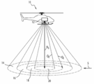
도 1은 전파 고도계를 구비한 항공기 및 지면 상에 연관된 수신 구역을 도해하여 묘사한다.
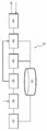
도 2는 본 발명의 일 실시예에 따라 전파를 송신-수신하는 무선 통신 장치의 주 기능 모듈을 보여준다.
도 3은 안테나 시스템의 방사 소자의 어레이를 도해하여 보여준다.
도 4는 도 3의 방사 소자의 어레이를 활성화/비활성화를 위한 제어 회로를 도해하여 보여준다.
도 5는 본 발명의 일 실시예에 따라 전파 고도계 시스템에 의해 시행되는 방법의 주요 단계(main step)의 플로우차트이다.Figure 1 illustrates an aircraft with a radio altimeter and an associated receiving area on the ground.
2 shows a main functional module of a radio communication apparatus for transmitting and receiving radio waves according to an embodiment of the present invention.
Figure 3 illustrates an array of radiating elements of an antenna system.
Figure 4 illustrates a control circuit for activating / deactivating the array of radiating elements of Figure 3;
5 is a flow chart of the main steps of a method implemented by a radio-altimeter system in accordance with an embodiment of the present invention.
분석되는 구역(analyzed zone)을 잘 컨트롤(better control) 하기 위하여 전파의 송신을 잘 타겟팅(better target)하는 것이 바람직한데, 이는 결국 상기 전파 고도계에 의해 상기 고도 계산의 정밀성을 향상시킨다.It is desirable to better target the transmission of the radio wave in order to better control the analyzed zone, which ultimately improves the accuracy of the altitude calculation by the radio altimeter.
본 발명의 한가지 목표는 기존 안테나 시스템에 비교하여 소형화(compactness)된 시스템을 보유(retain)하여 이러한 문제를 해결하는데 있다.One goal of the present invention is to solve this problem by retaining a compacted system as compared to conventional antenna systems.
이 목적을 달성하기 위하여, 첫 번째 측면(a first aspect)에 따라서, 본 발명은 전파를 송신하고 수신하는 무선 전자 장치 -상기 무선 전자 장치는 미리 설정된 변조 신호 및 트랜시버 안테나 시스템에 의해 주파수-변조된 전파를 생성하는 전파 발생기를 포함하고, 연관된 안테나 구경 값과 송신-수신 각을 갖고, 상기 송신된 전파를 송신하고 전파를 수신할 수 있음- 를 제안한다.To achieve this object, in accordance with a first aspect, the present invention provides a wireless electronic device for transmitting and receiving radio waves, said wireless electronic device comprising a frequency-modulated signal modulated by a predetermined modulation signal and a transceiver antenna system And a radio wave generator for generating a radio wave and having an associated antenna aperture value and a transmission-receiving angle, which can transmit the transmitted radio wave and receive the radio wave.
상기 안테나 시스템은 제1 주파수 대역으로 방사할 수 있는 방사 소자의 제1 어레이 및 제2 주파수 대역으로 방사할 수 있는 방사 소자의 적어도 하나의 제2 어레이와, 상기 방사 소자의 제1 어레이 및 제2 어레이 각각을 활성화 및/또는 비활성화 할 수 있는 복수의 활성화 소자, 및 선택된 안테나 구경 값에 기초하여 상기 활성화 소자를 제어할 수 있는 컨트롤 모듈을 포함한다.The antenna system comprising at least one second array of radiating elements capable of emitting in a first frequency band and a first array of radiating elements capable of emitting in a first frequency band, A plurality of activation elements capable of activating and / or deactivating each of the arrays, and a control module capable of controlling the activation elements based on the selected antenna aperture value.
유리하게도, 본 발명에 따라 전파를 송신-수신하기 위한 상기 무선 전자 장치는 방사 소자의 어레이를 활성화 또는 비활성화함으로써 동적으로 상기 안테나 구경을 선택할 수 있게 한다. 게다가, 방사 소자의 제1 어레이를 포함하는 안테나 시스템의 제2 주파수 대역으로 방사할 수 있는 적어도 방사 소자의 제2 어레이의 추가는 이것의 사이즈에 적은 영향을 미친다.Advantageously, the wireless electronic device for transmitting and receiving radio waves in accordance with the present invention enables dynamically selecting the antenna aperture by activating or deactivating the array of radiating elements. In addition, the addition of at least a second array of radiating elements capable of radiating into a second frequency band of an antenna system comprising a first array of radiating elements has a small effect on its size.
본 발명에 따라 전파를 송신-수신하기 위한 상기 무선 전자 장치는 하나 또는 이상의 아래 특징들을 가질 수 있고, 특징들은 독립적으로 또는 기술적으로 수용 가능한 모든 조합들이 고려될 수 있다.The wireless electronic device for transmitting and receiving radio waves in accordance with the present invention may have one or more of the following characteristics, and all of the features may be considered independently or technically acceptable.
이 장치는 선택된 안테나 구경 값을 획득하는 모듈을 포함한다.The apparatus includes a module for obtaining a selected antenna aperture value.
상기 안테나 시스템은 방사 소자의 제2 어레이의 행렬에 배열된 방사 소자의 복수의 제2 어레이를 포함하고, 방사 소자의 제2 어레이 각각은 고유의 전력 공급점을 갖는다.The antenna system includes a plurality of second arrays of radiating elements arranged in a matrix of a second array of radiating elements, each of the second arrays of radiating elements having a unique power supply point.
상기 활성화 [소자]는 스위치이고, 상기 장치는 상기 방사 소자의 제1 및 제2 어레이의 복수의 활성화/비활성화 구성을 생성하기 위해 배열된 복수의 스위치를 포함한다.The activation is a switch, and the device includes a plurality of switches arranged to generate a plurality of activation / deactivation configurations of the first and second arrays of radiating elements.
상기 안테나 구경 값은 안테나 구경 값들의 이산 집합 중에서 선택되고, 상기 이산 집합의 각각의 안테나 구경 값 각각은 상기 방사 소자의 제1 및 제2 어레이의 활성화/비활성화 구성에 대응된다.The antenna aperture value is selected from a discrete set of antenna aperture values, and each of the respective antenna aperture values of the discrete set corresponds to an activation / deactivation configuration of the first and second arrays of radiating elements.
이 장치는 메모리 모듈을 포함하고, 상기 안테나 구경 값들의 이산 집합 및 안테나 구경 값 각각을 위한 방사 소자의 상기 제1 및 제2 어레이의 연관된 활성화/비활성화 구성은 저장된다.The apparatus includes a memory module and an associated activated / deactivated configuration of the first and second arrays of radiating elements for each discrete set of antenna aperture values and antenna aperture values is stored.
다른 측면에 따르면, 본 발명은 간략히 상술한 것처럼 전파를 송신-수신하기 위한 무선 전자 장치에 의해 수행되는, 전파를 송신-수신하는 방법에 관련된다.According to another aspect, the present invention relates to a method for transmitting and receiving radio waves, which is performed by a wireless electronic device for transmitting and receiving radio waves, as briefly described above.
이 방법은 송신 또는 수신 모드에 다음의 단계를 포함한다.The method includes the following steps in the transmit or receive mode.
- 선택된 안테나 구경 값을 획득하는 단계,- obtaining a selected antenna aperture value,
- 상기 선택된 구경 값에 기초하여 상기 방사 소자의 제1 및 제2 어레이의 복수의 활성화/비활성화 소자를 제어하는 단계.- controlling a plurality of activation / deactivation elements of the first and second arrays of radiating elements based on the selected aperture value.
본 발명에 따라 전파를 송신-수신하는 이 방법은 하나 또는 이상의 아래 특징을 가질 수 있고, 아래 특징들은 독립적으로 또는 기술적으로 수용 가능한 모든 조합으로 고려될 수 있다.This method of transmitting and receiving radio waves in accordance with the present invention may have one or more of the following characteristics, and the following features may be considered in any combination, either independently or technically acceptable.
이것은 송신 모드에, 제1 주파수 대역의 미리 설정된 변조 신호에 의해 주파수-변조된 적어도 하나의 전파를 생성하는 단계를 더 포함한다.This further comprises generating at least one radio wave frequency-modulated by the predetermined modulation signal of the first frequency band in the transmission mode.
송신 모드에서, 다음과 같은 단계들을 포함한다.In the transmission mode, the following steps are included.
- 상기 선택된 안테나 구경 값을 안테나 구경 값의 최대값과 비교하는 단계,Comparing the selected antenna aperture value to a maximum value of an antenna aperture value,
- 상기 비교가 부정적(negative)인 경우, 상기 생성된 전파를 제2 주파수 대역으로 바꾸는(transpose) 단계.Transposing the generated radio wave to a second frequency band if the comparison is negative;
수신 모드에서, 이 방법은 다음과 같은 단계들을 더 포함한다.In the receive mode, the method further includes the following steps.
- 상기 선택된 안테나 구경 값을 안테나 구경 값의 최대값과 비교하는 단계,Comparing the selected antenna aperture value to a maximum value of an antenna aperture value,
- 상기 비교가 부정적(negative)인 경우, 상기 수신된 전파를 제1 주파수 대역으로 바꾸는(transpose) 단계.- transposing the received radio wave to a first frequency band if the comparison is negative.
다른 측면에 따르면, 본 발명은 에어본 시스템에 고정되기에 적합하고, 지면에 대해 상기 에어본 시스템의 거리를 제공하기에 적합하고, 간략히 상술한 바와 같이 전파를 송신-수신하기 위한 무선 전자 장치를 포함하고, 전파를 송신하고 상기 표면에서 반사된 전파를 수신할 수 있는 전파 고도계 시스템에 관련되고, 상기 전파 고도계 시스템은 상기 송신되고 반사된 전파의 함수로써 상기 거리를 계산할 수 있는 프로세싱 모듈을 더 포함한다.According to another aspect, the present invention is directed to a method of making a wireless electronic device adapted to be secured to an airborne system and adapted to provide a distance of the airborne system relative to the ground and to transmit and receive radio waves, Wherein the radio altimeter system further comprises a processing module capable of calculating the distance as a function of the transmitted and reflected radio waves, wherein the radio altimeter system includes a processing module capable of transmitting and receiving radio waves reflected from the surface do.
유리하게도, 상기 에어본 시스템과 상기 표면 사이의 거리의 계산 정확도는 상기 안테나 시스템의 상기 안테나 구경을 변화시킬 수 있음으로써 개선된다.Advantageously, the calculation accuracy of the distance between the airborne system and the surface is improved by being able to vary the antenna aperture of the antenna system.
본 발명의 다른 특징 및 이점은 첨부된 도면을 참조하여 정보로만(solely for information) 및 무제한적으로 아래에서 제공되는 설명으로부터 도출될 수 있다.Other features and advantages of the present invention may be derived from the following description provided solely for information and limitlessly with reference to the accompanying drawings.
본 발명에 따른 상기 무선 전자 장치는 에어본 시스템에 고정되어 전파 고도계 시스템(또는 전파 고도계)에 적용되는 것으로 묘사된다.The wireless electronic device according to the present invention is depicted as being fixed to an airborne system and applied to a radio altimeter system (or radio altimeter).
도 1에 도해된 예에서는, 항공기(10)는, 항공기(10)에 고정된 전파 고도계(12)를 구비하고, 이 예에서는 헬리콥터이다.In the example illustrated in Figure 1, the
전파 고도계(12)는 본 발명에 따라 전파를 송신-수신하는 (도 2의) 무선 전자 장치(30)을 구비하고, 안테나 시스템을 포함하고 타겟팅된 표면 S 쪽으로 전파 또는 전파의 빔(beam)을 송신할 수 있다.The
유리하게도, 전파를 송신-수신하는 상기 무선 전자 장치는 안테나 구경 값을 선택하고 상기 선택된 안테나 구경 값에 기초하여 다른 사이즈의 수신 구역(14, 16, 18, 및 20)을 획득할 수 있게 한다.Advantageously, the wireless electronic device transmitting and receiving radio waves allows the selection of an antenna aperture value and acquisition of different sized receive
전파 고도계(12)의 목적은, 하나 또는 이상의 송신된 전파 OE 및 반사된 전파 OR에 기초하여 오버플로운 거리(overflown distance) H0 의 최소값을 예측하는 것이다.The purpose of the radio-
일 실시예에 있어서, 각각의 송신된 전파는, 예를 들어 Fmin값에서부터 Fmax값 사이 범위의 주파수 변화 램프(frequency variation ramp)에 따라서, 주파수 스윙(frequency swing) ΔF = abs(Fmax - Fmin)에 따라, 주파수-변조되었다 -abs는 절대값을 나타냄-. 전파 OE는 지면 S에서 반사되고, 반사된 전파 OR을 생성한다. 이 동작 모드는 "FMCW(frequency-modulated continuous wave)"라고 불린다.In one embodiment, each of the transmitted radio wave is, for example, F min F max values from the frequency variation value in the range lamp (frequency variation ramp) to Thus, the swing frequency (frequency swing) ΔF = abs ( F max - F min ), and frequency-modulated -abs represents the absolute value. Propagation O E is reflected from the surface S, and generates a reflected electric wave O R. This mode of operation is called "frequency-modulated continuous wave (FMCW) ".
본 발명의 응용은 전파 고도계의 이 동작 모드에 한정되지 않음을 특히 주의해야 한다.It should be noted that the application of the present invention is not limited to this mode of operation of the radio altimeter.
수신 구역(14, 16, 18, 및 20)은 상기 선택된 안테나 구경 값에 기초하여 다양한 사이즈를 갖는다.The receive
지면의 수신 구역 또는 스팟(sot) 각각은, 주어진 안테나 구경 값으로 전송되는 전파의 방사 구역(radiation zone)이다.Each receiving area or spot on the ground is a radiation zone of radio waves transmitted at a given antenna aperture value.
도 1에 표시된 모든 수신 구역(14 내지 20)은 설명하기 위한 목적임을 특히 주의해야 한다. 실제는, 그리고 하기에서 상세히 설명되는 바와 같이, 안테나 구경 값의 선택에 따른, 수신 구역(14 내지 20) 중 단일의(single) 수신 구역이 효율적이다.It should be particularly noted that all receive zones 14-20 shown in FIG. 1 are for illustrative purposes. In practice, and as will be described in detail below, a single receiving zone of the receiving
도 1의 예에서, 수신 구역(14)은 전자기 스펙트럼의 제1 주파수 대역에, 예를 들어 4GHz에서 8GHz의 주파수로 정의되는 C 대역에, 도해되어 표시된다.In the example of FIG. 1, the receive
수신 구역(20)은 전자기 스펙트럼의 제2 주파수 대역에, 예를 들어 27 GHz에서 40GHz의 주파수로 정의되는 Ka 대역에, 대응한다.The receiving
게다가, 추가적인 두 수신 구역(16, 18)은 제2 주파수 대역의 방사 소자의 다른 어레이의 선택에 대응한다.In addition, the two additional receive
즉, 전파를 송신-수신하는 상기 무선 전자 장치의 상기 안테나 시스템은 설명된 실시예에 따라, 제2 주파수 대역에서 선택될 수 있는, 다른 사이즈의 수신 구역에 대응하여, 두 주파수 대역 - 상기 두 주파수 대역은 제1 주파수 대역 또는 낮은 대역(low band)과, 제2 주파수 대역 또는 높은 대역(high band)임 -, 및 몇몇 안테나 구경 값에서 작동할 수 있다.That is, the antenna system of the wireless electronic device transmitting and receiving radio waves, in accordance with the described embodiment, corresponds to receiving areas of different sizes, which can be selected in the second frequency band, The band may operate at a first frequency band or a low band, a second frequency band or a high band, and at some antenna aperture values.
하기에서 더 상세히 설명하는 바와 같이, 이 다른 안테나 구경 값들은 전력 공급원에 의해 방사 안테나 소자의 활성화 또는 비활성화 제어를 통해 달성(achieve)될 수 있다.As will be explained in more detail below, these different antenna aperture values may be achieved by controlling the activation or deactivation of the radiating antenna element by a power source.
도 2는 본 발명의 일 실시예에 따라 전파를 송신-수신하는 무선 전자 장치의 주 기능 유닛을 도해적으로 묘사하고, 이는 전파 고도계에 통합될 수 있고, 복수의 안테나 구경 값들 중에서 하나의 안테나 구경 값을 선택할 수 있게 한다.2 schematically depicts a main functional unit of a wireless electronic device that transmits and receives radio waves in accordance with one embodiment of the present invention, which may be incorporated into a radio altimeter and includes a plurality of antenna aperture values, Allows you to select a value.
무선 전자 장치(30)는 메모리(34)에 저장된 다양한 동작 파라미터(operating parameters)를 획득하는 입력 인터페이스 모듈(32), 및 안테나 구경 값을 획득하는 모듈(36)을 포함한다..The wireless
일 실시예에 있어서, 모듈(36)은 오퍼레이터(operator)로부터 안테나 구경 값을 수신한다.In one embodiment, the
선택적으로, 모듈(36)은 주어진 응용(application)에서 최적화된 안테나 구경 값을 선택하는 루프 동작(operation in a loop)을 위해, 예를 들어 무선 전자 장치(30)가 전파 고도계에 통합되면 고도 H0를 계산을 위해, 다른 계산(computation) 모듈로부터 안테나 구경 값을 수신한다.Optionally, the
무선 전자 장치(30)는 제1 주파수 대역에서, 예를 들어 C 대역에서, 전파를 생성하는 모듈(38)을 포함한다.The wireless
전파를 제2 주파수 대역으로 바꾸는(transpose) 모듈(40)은, 안테나 구경 값을 획득하는 모듈(36)에 의해 획득된, 선택된 구경 값에 기초하여 선택적으로 시행될 수 있다. 예를 들어, 제2 주파수 대역은 Ka 대역이다.The
실제로, 안테나 구경 값이 안테나 구경값의 최대값에 대응하면, 제2 주파수 대역보다 낮은 제1 주파수 대역에서 전파 송신이 이뤄진다.In practice, if the antenna aperture value corresponds to the maximum value of the antenna aperture value, the radio wave transmission occurs in the first frequency band lower than the second frequency band.
선택적으로, 모듈(38 및 40)은 파라미터(parameter)에 의해 선택된 주파수 대역의 전파를 생성하고 형성(shape)하는 단일 모듈로 교체된다.Optionally, the
제어 모듈(42)은 송신 및 수신에 사용될 안테나 시스템(44)의 방사 소자를 선택할 수 있게 한다.The
실제로, 안테나 시스템(44)은 제1 주파수 대역에서 송신할 수 있는 방사 소자의 제1 어레이를 포함한다.In practice, the
이는 또한 제2 주파수 대역에서 송신할 수 있는 방사 소자의 제2 어레이의 집합을 포함한다.It also includes a second set of arrays of radiating elements capable of transmitting in a second frequency band.
도 3은 일 실시예에 따른 안테나 시스템(44)을 도해적으로 묘사한다.FIG. 3 diagrammatically depicts an
상기 시스템은, 낮은 대역(46a, 46b, 46c, 및 46d)에서 동작하고 반사 서포트 면(reflective support plane; 48)에 위치하고 각각은 전력 공급점(50a, 50b, 50c, 및 50d)을 포함하는 제1 방사 소자의 제1 어레이(45)를 포함한다.The system operates at
이 실시예에서, 높은 대역에서 동작하는 방사 소자의 제2 어레이(521, ..., 52i, ..., 52n)는 같은 서포트 면(48)에 위치한다.In this embodiment, the second array of radiating elements 52 1 , ..., 52 i , ..., 52 n , operating in the higher bands, are located on the
방사 소자의 제2 어레이 각각은 방사 소자의 일반 패드(regular pad) 또는 기초 패치(elementary patches; 54)로 생성되어 일반 매쉬(regular mesh)로 배열된다.Each of the second arrays of radiating elements is created as a regular pad or
도시된 예에서, 상기 일반 매쉬는 정사각형이나, 어떠한 다른 일반 매쉬도 고려될 수 있다.In the illustrated example, the generic mesh is square, but any other generic mesh may be considered.
예를 들어, 한 대안에 따르면, 제2 방사 소자는 콘센트릭 링(concentric ring)에 배열된다.For example, according to one alternative, the second radiating element is arranged in a concentric ring.
제2 어레이(521 내지 52n)는 방사 소자의 제2 어레이의 행렬(55)에 배열된다.The second arrays 52 1 to 52 n are arranged in a
방사 소자의 제2 어레이(52i) 각각은 전력 공급점(58i)를 포함하고, 송신 및 수신을 위한 어레이를 활성화 또는 비활성화 할 수 있게 한다.A second array (52 i) each of the radiating elements makes it possible to include a power supply point (58 i), and enable or disable the array for transmission and reception.
유리하게도, 방사 소자의 제2 어레이(52i) 각각은, 컨트롤 모듈(42)에 의해 활성화되는 제2 어레이의 집합에서 다양한 선택(various selections)을 생성하기 위하여 개별적으로 활성화되고, 다른 안테나 구경 값에 대응하는 전파의 빔(beam)을 송신하고 수신할 수 있는 방사 소자의 제2 어레이의 송신-수신 구성을 형성한다. 안테나 시스템은 다중의 선택가능한 안테나 구경 값들로 획득된다.Advantageously, each of the second arrays 52 i of radiating elements is individually activated to produce various selections in a second set of arrays activated by the
예를 들어, 방사 소자의 제1 어레이(45)는 도 1의 수신 구역(14)을 획득할 수 있게 하고, 제2 어레이의 전체 행렬(55)을 활성화하는 것은 도 1의 수신 구역 20을 획득할 수 있게 한다.For example, the
서브-행렬(56)을 형성하는 제2 방사 어레이의 집합의 활성화는 수신 구역(18)을 획득할 수 있게 하고, 단일 정사각형(52i)을 활성화는 구역(16)을 획득할 수 있게 한다.Activation of the second set of radiation arrays forming the sub-matrix 56 enables acquisition of the receiving
여기서, 우리는 활성화된 방사 소자의 제2 어레이의 4 설정의 선택을 묘사했는데, 방사 소자의 고려된 어레이의 수와 배열에 기초하여 4보다 큰 N개의 설정이 획득될 수 있다.Here, we have described the selection of four settings of the second array of activated radiating elements, where N settings greater than 4 can be obtained based on the number and arrangement of the considered arrays of radiating elements.
도 4는 도 3의 방사 소자의 어레이를 활성화/비활성화 하는 회로(60)를 도해적으로 묘사한다. 도 3의 대응하는 방사 소자의 제1 및 제2 어레이의 다양한 전력 공급점, 및 활성화 소자는, 예를 들어 스위치는, 방사 소자의 다양한 어레이의 활성화 및 비활성화를 제어할 수 있게 한다.FIG. 4 diagrammatically depicts a
전기 회로(60)은 방사 소자의 제1 어레이의 전력 공급점(62), 및 제2 어레이의 고려된 집합을 작동시키기 위한(powering) 전력 공급점(64, 66, 68)을 포함한다.The
더 일반적으로, 안테나 구경 값과 연관된 방사 소자의 제1 및 제2 어레이의 집합의 각각은 연관된 전력 공급점을 갖는다.More generally, each of the first and second sets of arrays of radiating elements associated with antenna aperture values has an associated powering point.
도 4의 회로는 방사 소자의 제1 및 제2 어레이에 전력을 공급하는, 또는 공급하지 않는 스위치(701, ..., 70k, ..., 70n)를 포함한다.The circuit of Figure 4 includes switches 70 1 , ..., 70 k , ..., 70 n that supply or do not supply power to the first and second arrays of radiating elements.
선택적으로, 활성화/비활성화 소자(701, ..., 70k, ..., 70n)는 스위치다.Optionally, the activation / deactivation elements 70 1 , ..., 70 k , ..., 70 n are switches.
활성화 소자((701 내지 70n)의 다양한 개방(opening)/닫힘(closing) 설정이 제공되고, 각 설정은 주어진 안테나 구경 값 및 방사 소자 어레이의 집합에 대응된다.Various opening / closing settings of the activating elements 70 1 through 70 n are provided and each setting corresponds to a given antenna aperture value and a set of radiating element arrays.
연관된 안테나 구경 값과 다양한 스위치의 위치 사이의 관련성을 나타내는 상기 다양한 설정은 메모리 모듈(34)에, 예를 들어 레지스터(registers)나 파일에, 저장된다.The various settings indicating the association between the associated antenna aperture value and the location of the various switches are stored in the
즉, 안테나 시스템(44)과 연관된 안테나 구경의 선택(choice)은, 회로(60)의 다양한 활성화 소자의 위치의 선택에 기인하여 만들어진다.That is, the choice of antenna aperture associated with the
다른 안테나 구경 값들의 이산 집합이 획득될 수 있다.A discrete set of different antenna aperture values can be obtained.
본 발명의 일 실시예에 따르면, 에어본 시스템에 고정되기에 적합하고, 지면에 대한 상기 에어본 시스템의 거리를 제공하기에 적합한 전파 고도계는, 상술한 무선 전자 장치 및 송신되고 반사된 전파의 함수로써 상기 거리를 계산할 수 있는 프로세싱 모듈을 포함한다.According to one embodiment of the present invention, a radio altimeter suitable for being fixed to an airborne system and suitable for providing a distance of the airborne system to the ground includes a radio electronic device as described above and a function of the transmitted and reflected radio waves And a processing module capable of calculating the distance.
도 5는 오버플로운 표면(overflown surface)에 관련된 거리를 계산하는, 상술한 무선 주파수(radio frequency) 장치를 포함하는 전파 고도계에 의해 수행되는 주요 단계의 플로우 차트이다.5 is a flow chart of the main steps performed by a radio altimeter including the above-described radio frequency device, which calculates the distance associated with an overflow surface.
단계(80) 동안, 적용될 안테나 구경 값 VA는 오퍼레이터의 컨트롤 하에서 인간-컴퓨터 인터페이스(man-machine interface)를 통해, 또는 하기에서 설명되는 계산에 의해 획득된다.During
전송될 전파의 빔(beam)은 제1 주파수 대역에서, 예를 들어 C 대역에서, 단계(82) 동안 생성된다.A beam of the radio wave to be transmitted is generated during the
확인(verification)하는 단계(84) 동안은, 안테나 구경 값이 이전에 저장된 구경 값의 최대값과 같은지 확인된다.During the
부정적인 응답의 경우, 단계(84) 다음에는, 전송될 상기 전파를 제2 주파수 대역으로, 예를 들어 Ka 대역으로, 바꾸는(transposition) 단계(86)가 뒤따른다.In the case of a negative response, following
확인하는 단계(84)가 긍정적인 응답의 경우, 또는 바꾸는 단계(86)의 다음에는, 안테나 구경 값 VA에 기초하여, 컨트롤 회로의 스위치의 개방/닫힘 설정과 다양한 가능한 안테나 구경 값을 매칭하는 이전에 저장된 설정으로부터 결정하는 단계를 포함하는 방사 소자를 전송하는 어레이를 선택하는 단계(88)가 뒤따른다.If the identifying
예를 들어, 상기 안테나 구경 값 VA가 구경 값의 최대값인 경우, 방사 소자의 제1 어레이만이 활성화된다.For example, if the antenna aperture value V A is the maximum value of the aperture value, only the first array of radiating elements is activated.
방사 소자를 송신하는 어레이를 선택하는 단계(88)는, 전파의 송신 및 방사 소자의 다양한 선택된 어레이의 전기 공급을 가능하게 하는 스위치의 활성화/비활성화 제어에 적용된다.The
수신 모드에서, 방사 소자의 어레이의 활성화/비활성화는 또한 단계(90)에서 상기 안테나 구경 값 VA에 기초하여 수행된다.In the receive mode, activation / deactivation of the array of radiating elements is also performed in
단계(90) 다음에는, 단계(84)와 비슷하게, 안테나 구경 값 VA이 이전에 저장된 구경 값의 최대값과 같은지 확인하기 위해 확인하는 단계(92)가 뒤따른다.
부정적인 응답의 경우, 단계(92) 다음에는 상기 수신한 전파를 제1 주파수 대역으로 바꾸기 위해 바꾸는 단계(94)가 뒤따른다.In the case of a negative response,
확인하는 단계(92)가 긍정적인 응답의 경우, 또는 단계(94) 이후에, 단계(96)는, 적용 가능한 경우(if applicable), 제1 주파수 대역으로 바뀐(transposed) 상기 수신한 전파의 다양한 수신 및 복조(demodulation) 동작을 수행한다.If the identifying
다음, 수신한 전파를 반사한 표면과 상기 전파 고도계 사이의 거리를 추출하고 계산하는 단계(98)가 적용된다.Next, a step (98) of extracting and calculating the distance between the surface reflecting the received radio wave and the above-mentioned radio wave altimeter is applied.
본 발명에 특정하고(specific to it), 본 발명의 미션(mission)에 기초한 방법에 따라 전파 고도계가, 분석된 수신 구역이 만족되지 않는다고 결정하면, 본 발명은 새로운 안테나 구경 값을 명령할 것이다. 사용된 안테나 구경 값 VA보다 작은 새로운 안테나 구경 값이 획득되고 단계(80 내지 98)가 반복된다.If the radio altimeter determines in accordance with the mission-based method of the present invention that the analyzed receiving region is not satisfied, the present invention will command a new antenna aperture value. A new antenna aperture value smaller than the used antenna aperture value V A is obtained and steps 80-98 are repeated.
유리하게도, 이 실시예는 제1 주파수 대역에서 전통적인(traditional) 전파 프로세싱 동작을 수행한다.Advantageously, this embodiment performs traditional radio propagation operations in the first frequency band.
유리하게도, 알려진 C 대역의 전파 고도계 -상기 전파 고도계는 안테나 구경 값들을 획득하고, 제1 및 제2 주파수 대역 사이의 바꿈(transposition)을 수행하고, 송신 및 수신에 사용되는 방사 소자의 활성화/비활성화를 제어하는 모듈들을 추가함으로써 변형됨- 는 유용하다.Advantageously, a known C-band propagation altimeter-the radio altimeter-obtains antenna aperture values, performs transposition between the first and second frequency bands, and activates / deactivates the radiating elements used for transmission and reception Which is modified by adding modules that control it.
즉, 제안된 솔루션(solution)은 장치의 소형화를 유지하며 저 생산 비용을 갖는다.That is, the proposed solution maintains the miniaturization of the device and has a low production cost.
본 발명은 다른 두 주파수 대역에서 송신하고 수신하는 무선 주파수 장치에 적용되는 것으로 묘사됐다. 하지만, 본 발명은 이러한 어플리케이션 시나리오(application scenario)에 한정되지 않고, 다양한 안테나 구경 값을 획득하기 위해 각각의 주파수 대역에서 선택될 수 있는 방사 소자의 어레이와, 2 이상의 주파수 대역과의 동작에 적용될 수 있다.The present invention has been described as applying to a radio frequency device transmitting and receiving in two different frequency bands. However, the present invention is not limited to such application scenarios, but may be applied to an array of radiating elements that can be selected in each frequency band to obtain various antenna aperture values, have.
Claims (11)
상기 안테나 시스템(44)은,
제1 주파수 대역(a first frequency band)으로 방사할 수 있는 방사 소자(radiating elements; 50a, 50b, 50c, 50d)의 제1 어레이(a first array; 45), 및 제2 주파수 대역(a second frequency band)으로 방사할 수 있는 방사 소자의 적어도 하나의 제2 어레이(second array; 52i, 55, 56)와,
상기 방사 소자의 제1 어레이 및 제2 어레이 각각을 활성화 및/또는 비활성화할 수 있는 복수의 활성화 소자(activation elements; 701, ..., 70i, ..., 70n), 및
선택된 안테나 구경 값에 기초하여 상기 활성화 소자(701, ..., 70i, ..., 70n)를 제어할 수 있는 컨트롤 모듈(a control module; 42)
을 포함하는 특징이 있는 무선 전자 장치.A wireless electronic device for transmitting and receiving radio waves comprising a radio wave generator for generating a radio wave with a predetermined modulation signal and a frequency-modulated by a transceiver antenna system, The wireless electronic device has an associated antenna aperture value and a transmission-reception angle and is capable of transmitting said transmitted radio waves and receiving a radio wave In -
The antenna system (44)
A first array 45 of radiating elements 50a, 50b, 50c and 50d that can radiate in a first frequency band and a second array 45 of radiating elements 50a, at least one second array (52 i , 55, 56) of radiating elements capable of radiating into a band,
A plurality of activation elements 70 1 , ..., 70 i , ..., 70 n capable of activating and / or deactivating the first and second arrays of radiating elements, respectively, and
A control module 42 for controlling the activation elements 70 1 , ..., 70 i , ..., 70 n based on the selected antenna aperture value,
The wireless device comprising:
선택된 안테나 구경 값을 획득하는 모듈(36)을 포함하는 특징이 있는 무선 전자 장치.The method according to claim 1,
And a module (36) for obtaining a selected antenna aperture value.
상기 안테나 시스템은 방사 소자의 제2 어레이의 행렬(matrix; 55)에 배열된 방사 소자의 복수의 제2 어레이(521, ..., 52i, ..., 52n)를 포함하고,
방사 소자의 제2 어레이 각각은 고유의 전력 공급점(power supply point)을 갖는 특징이 있는 무선 전자 장치.3. The method according to claim 1 or 2,
The antenna system comprises a plurality of second arrays of radiating elements (52 1 , ..., 52 i , ..., 52 n ) arranged in a matrix (55) of a second array of radiating elements,
Wherein each of the second arrays of radiating elements has a unique power supply point.
상기 활성화 소자(701, ..., 70i, ..., 70n)는 스위치고, 및
상기 장치는 상기 방사 소자의 제1 및 제2 어레이의 복수의 활성화/비활성화 구성(configurations)을 생성하기 위해 배열된 복수의 스위치를 포함하는 특징이 있는 무선 전자 장치.4. The method according to any one of claims 1 to 3,
The activation elements 70 1 , ..., 70 i , ..., 70 n are switch switches,
Wherein the apparatus comprises a plurality of switches arranged to produce a plurality of activation / deactivation configurations of the first and second arrays of radiating elements.
상기 안테나 구경 값은 안테나 구경 값들의 이산 집합(discrete set) 중에서 선택되고, 상기 이산 집합의 안테나 구경 값 각각은 상기 방사 소자의 제1 및 제2 어레이의 활성화/비활성화 구성에 대응되는 특징이 있는 무선 전자 장치.5. The method of claim 4,
Wherein the antenna aperture value is selected from a discrete set of antenna aperture values and each antenna aperture value of the discrete set corresponds to an activation / deactivation configuration of the first and second arrays of radiating elements, Electronic device.
메모리 모듈(34)를 포함하고,
상기 안테나 구경 값들의 이산 집합 및 안테나 구경 값 각각을 위한 방사 소자의 상기 제1 및 제2 어레이의 연관된 활성화/비활성화 구성은, 저장되는 특징이 있는 무선 전자 장치.6. The method of claim 5,
Memory module 34,
Wherein the associated activated / deactivated configuration of the first and second arrays of radiating elements for each discrete set of antenna aperture values and antenna aperture values is stored.
송신 또는 수신 모드는,
선택된 안테나 구경 값을 획득하는 단계(80);
상기 선택된 구경 값에 기초하여 상기 방사 소자의 제1 및 제2 어레이의 복수의 활성화/비활성화 소자를 제어하는 단계(88, 90)
를 포함하는 특징이 있는 방법.7. A method of transmitting and receiving radio waves, carried out by a wireless electronic device for transmitting and receiving radio waves according to any one of claims 1 to 6,
In the transmission or reception mode,
Obtaining (80) a selected antenna aperture value;
Controlling (88, 90) a plurality of activation / deactivation elements of the first and second arrays of radiating elements based on the selected aperture value,
/ RTI >
송신 모드는,
제1 주파수 대역의 미리 설정된 변조 신호에 의해 주파수-변조된 적어도 하나의 전파를 생성하는 단계(82)
를 더 포함하는 특징이 있는 방법.8. The method of claim 7,
In the transmission mode,
Generating (82) at least one frequency-modulated radio wave by a predetermined modulation signal in a first frequency band,
The method further comprising:
방출 모드(emission mode)는,
상기 선택된 안테나 구경 값을 안테나 구경 값의 최대값과 비교하는 단계(84);
상기 비교가 부정적(negative)인 경우, 상기 생성된 전파를 제2 주파수 대역으로 바꾸는(transpose) 단계(86)
를 포함하는 특징이 있는 방법.9. The method of claim 8,
In an emission mode,
Comparing (84) the selected antenna aperture value to a maximum value of an antenna aperture value;
If the comparison is negative, transposing the generated radio wave to a second frequency band 86,
/ RTI >
수신 모드는,
상기 선택된 안테나 구경 값을 안테나 구경 값의 최대값과 비교하는 단계(92);
상기 비교가 부정적(negative)인 경우, 상기 수신된 전파를 상기 제1 주파수 대역으로 바꾸는(transpose) 단계(94)
를 더 포함하는 특징이 있는 방법.10. The method according to any one of claims 7 to 9,
In the reception mode,
Comparing the selected antenna aperture value to a maximum antenna aperture value (92);
Transposing (94) the received radio wave to the first frequency band if the comparison is negative,
The method further comprising:
제1항 내지 제6항 중 어느 한 항에 따라 전파를 송신-수신하고, 상기 전파를 송신할 수 있고 상기 표면에서 반사된 전파를 수신할 수 있는 무선 전자 장치를 포함하고,
상기 송신되고 반사된 전파의 함수(function)로써 상기 거리를 계산할 수 있는 프로세싱 모듈(processing module)을 더 포함하는 특징이 있는 전파 고도계 시스템.A radio altimeter system suitable for being fastened to an airborne system and providing a distance of the airborne system to the ground,
A wireless electronic device capable of transmitting and receiving radio waves according to any one of claims 1 to 6 and capable of transmitting the radio waves and receiving radio waves reflected from the surface,
Further comprising a processing module capable of calculating said distance as a function of said transmitted and reflected radio waves.
Applications Claiming Priority (2)
| Application Number | Priority Date | Filing Date | Title |
|---|---|---|---|
| FR1501559 | 2015-07-22 | ||
| FR1501559A FR3039328B1 (en) | 2015-07-22 | 2015-07-22 | RADIOELECTRIC RADIOELECTRIC WAVE TRANSMIT-RECEIVE DEVICE AND ASSOCIATED RADIO ALTIMETRY SYSTEM |
Publications (1)
| Publication Number | Publication Date |
|---|---|
| KR20170012142A true KR20170012142A (en) | 2017-02-02 |
Family
ID=55022504
Family Applications (1)
| Application Number | Title | Priority Date | Filing Date |
|---|---|---|---|
| KR1020160093689A KR20170012142A (en) | 2015-07-22 | 2016-07-22 | Radioelectric device for transmitting and receiving radioelectric waves and associated radio altimetry system |
Country Status (7)
| Country | Link |
|---|---|
| US (1) | US10502825B2 (en) |
| EP (1) | EP3121902B1 (en) |
| JP (1) | JP6870932B2 (en) |
| KR (1) | KR20170012142A (en) |
| ES (1) | ES2715015T3 (en) |
| FR (1) | FR3039328B1 (en) |
| IL (1) | IL246878B (en) |
Families Citing this family (4)
| Publication number | Priority date | Publication date | Assignee | Title |
|---|---|---|---|---|
| FR3069523A1 (en) * | 2017-07-27 | 2019-02-01 | Prodose | METHOD OF MAKING A NETWORK FOR THE SUPPLY OF THE INTERNET IN PARTICULAR ON THE SURFACE OF THE GLOBE TERRESTRIAN, A PLANE FOR CARRYING OUT IT |
| GB2569620B (en) * | 2017-12-21 | 2021-12-29 | Canon Kk | Optimization of the performances of an antenna array |
| FR3103569B1 (en) * | 2019-11-27 | 2021-12-10 | Thales Sa | RADAR, FLYING MACHINE CONTAINING SUCH A RADAR, PROCESSING FOR PROCESSING IN A RADAR EMBEDDED IN A FLYING MACHINE AND ASSOCIATED COMPUTER PROGRAM |
| KR102325365B1 (en) * | 2021-05-04 | 2021-11-10 | 국방과학연구소 | Compact integrated apparatus of interferometric radar altimeter and radar altimeter capable of performing individual missions by altitude and operating method thereof |
Family Cites Families (13)
| Publication number | Priority date | Publication date | Assignee | Title |
|---|---|---|---|---|
| FR1501559A (en) * | 1966-11-17 | 1967-11-10 | Professional photographic camera with rapid and multiple loading and unloading by film plan | |
| GB2157500B (en) * | 1984-04-11 | 1987-07-01 | Plessey Co Plc | Microwave antenna |
| JPH02287181A (en) * | 1989-04-27 | 1990-11-27 | Matsushita Electric Works Ltd | On-vehicle radar system |
| JPH03119779U (en) * | 1990-03-20 | 1991-12-10 | ||
| JPH0440003A (en) * | 1990-06-05 | 1992-02-10 | Mitsubishi Electric Corp | Multilayered array antenna |
| US5549002A (en) * | 1994-07-01 | 1996-08-27 | General Electric Company | Method for detecting and characterizing flaws in engineering materials |
| GB2330236A (en) * | 1997-10-11 | 1999-04-14 | Secr Defence | A dual band phased array antenna |
| JP4558548B2 (en) * | 2005-03-15 | 2010-10-06 | 株式会社リコー | Microstrip antenna, radio module, radio system, and microstrip antenna control method |
| JP4654803B2 (en) * | 2005-07-07 | 2011-03-23 | 日産自動車株式会社 | Radar device for vehicle periphery monitoring |
| DE102006032539A1 (en) * | 2006-07-13 | 2008-01-17 | Robert Bosch Gmbh | FMCW radar sensor |
| GB0902314D0 (en) * | 2009-02-12 | 2009-04-01 | Trw Ltd | Antennas |
| KR101223804B1 (en) * | 2011-01-25 | 2013-01-17 | 주식회사 만도 | Detection sensor |
| US8903454B2 (en) * | 2011-11-07 | 2014-12-02 | Alcatel Lucent | Base station and radio unit for creating overlaid sectors with carrier aggregation |
-
2015
- 2015-07-22 FR FR1501559A patent/FR3039328B1/en not_active Expired - Fee Related
-
2016
- 2016-07-20 EP EP16180427.3A patent/EP3121902B1/en active Active
- 2016-07-20 ES ES16180427T patent/ES2715015T3/en active Active
- 2016-07-21 JP JP2016143765A patent/JP6870932B2/en active Active
- 2016-07-21 US US15/216,530 patent/US10502825B2/en active Active
- 2016-07-21 IL IL246878A patent/IL246878B/en active IP Right Grant
- 2016-07-22 KR KR1020160093689A patent/KR20170012142A/en not_active IP Right Cessation
Also Published As
| Publication number | Publication date |
|---|---|
| FR3039328B1 (en) | 2017-08-25 |
| US10502825B2 (en) | 2019-12-10 |
| FR3039328A1 (en) | 2017-01-27 |
| EP3121902B1 (en) | 2018-11-14 |
| JP6870932B2 (en) | 2021-05-12 |
| EP3121902A1 (en) | 2017-01-25 |
| IL246878B (en) | 2020-08-31 |
| IL246878A0 (en) | 2016-12-29 |
| ES2715015T3 (en) | 2019-05-31 |
| US20170227635A1 (en) | 2017-08-10 |
| JP2017026618A (en) | 2017-02-02 |
Similar Documents
| Publication | Publication Date | Title |
|---|---|---|
| JP7036744B2 (en) | Radar system for tracking low-flying unmanned aerial vehicles and objects | |
| KR20170012142A (en) | Radioelectric device for transmitting and receiving radioelectric waves and associated radio altimetry system | |
| WO2016195765A1 (en) | Methods and apparatus for mobile phased array system | |
| KR20180060341A (en) | Radar Apparatus and Antenna Apparatus therefor | |
| US20210132190A1 (en) | Implementing non-point targets using direct synthesis of radar signals | |
| KR20150123372A (en) | Hybrid satellite navigation signal generator | |
| JP2005233723A (en) | Distributed aperture radar device | |
| JP2017026618A5 (en) | ||
| RU2670980C9 (en) | Multifunctional on-board radar complex | |
| US7280072B2 (en) | System for the relative navigation of aircraft and spacecraft using a phased array antenna | |
| RU2624736C2 (en) | Radar station circular view "resonance" | |
| RU2527923C2 (en) | Method of creating spatial navigation field with distributed navigation signal sources | |
| RU155321U1 (en) | RADAR STS-177 | |
| CA2940292C (en) | Scanning meta-material antenna and method of scanning with a meta-material antenna | |
| KR101754236B1 (en) | Millimeter-wave seeker | |
| RU2742943C1 (en) | Radar interrogator with system of active phased arrays | |
| US11879968B2 (en) | Simultaneous beamforming and multiple input-multiple output (MIMO) schemes in radar system | |
| RU155330U1 (en) | RADAR STS-178 | |
| JP2016085167A (en) | Object detection device and object detection method | |
| RU2602072C1 (en) | Passive coherent radar system of decametre range | |
| WO2003087872A1 (en) | Method for verifying dynamically a multiple beam antenna placed on a vehicle |
Legal Events
| Date | Code | Title | Description |
|---|---|---|---|
| A201 | Request for examination | ||
| E902 | Notification of reason for refusal | ||
| AMND | Amendment | ||
| E90F | Notification of reason for final refusal | ||
| AMND | Amendment | ||
| E601 | Decision to refuse application | ||
| AMND | Amendment | ||
| X601 | Decision of rejection after re-examination |