KR20170011990A - Inkjet printer, printing method using the same, and automatic web threading method - Google Patents
Inkjet printer, printing method using the same, and automatic web threading method Download PDFInfo
- Publication number
- KR20170011990A KR20170011990A KR1020160035732A KR20160035732A KR20170011990A KR 20170011990 A KR20170011990 A KR 20170011990A KR 1020160035732 A KR1020160035732 A KR 1020160035732A KR 20160035732 A KR20160035732 A KR 20160035732A KR 20170011990 A KR20170011990 A KR 20170011990A
- Authority
- KR
- South Korea
- Prior art keywords
- continuous paper
- roller
- paper
- pin
- printing
- Prior art date
Links
Images


Classifications
-
- B—PERFORMING OPERATIONS; TRANSPORTING
- B41—PRINTING; LINING MACHINES; TYPEWRITERS; STAMPS
- B41J—TYPEWRITERS; SELECTIVE PRINTING MECHANISMS, i.e. MECHANISMS PRINTING OTHERWISE THAN FROM A FORME; CORRECTION OF TYPOGRAPHICAL ERRORS
- B41J11/00—Devices or arrangements of selective printing mechanisms, e.g. ink-jet printers or thermal printers, for supporting or handling copy material in sheet or web form
- B41J11/18—Platen-impression arrangements
-
- B—PERFORMING OPERATIONS; TRANSPORTING
- B41—PRINTING; LINING MACHINES; TYPEWRITERS; STAMPS
- B41J—TYPEWRITERS; SELECTIVE PRINTING MECHANISMS, i.e. MECHANISMS PRINTING OTHERWISE THAN FROM A FORME; CORRECTION OF TYPOGRAPHICAL ERRORS
- B41J2/00—Typewriters or selective printing mechanisms characterised by the printing or marking process for which they are designed
- B41J2/005—Typewriters or selective printing mechanisms characterised by the printing or marking process for which they are designed characterised by bringing liquid or particles selectively into contact with a printing material
- B41J2/01—Ink jet
-
- B—PERFORMING OPERATIONS; TRANSPORTING
- B41—PRINTING; LINING MACHINES; TYPEWRITERS; STAMPS
- B41J—TYPEWRITERS; SELECTIVE PRINTING MECHANISMS, i.e. MECHANISMS PRINTING OTHERWISE THAN FROM A FORME; CORRECTION OF TYPOGRAPHICAL ERRORS
- B41J15/00—Devices or arrangements of selective printing mechanisms, e.g. ink-jet printers or thermal printers, specially adapted for supporting or handling copy material in continuous form, e.g. webs
- B41J15/16—Means for tensioning or winding the web
- B41J15/165—Means for tensioning or winding the web for tensioning continuous copy material by use of redirecting rollers or redirecting nonrevolving guides
-
- B—PERFORMING OPERATIONS; TRANSPORTING
- B41—PRINTING; LINING MACHINES; TYPEWRITERS; STAMPS
- B41J—TYPEWRITERS; SELECTIVE PRINTING MECHANISMS, i.e. MECHANISMS PRINTING OTHERWISE THAN FROM A FORME; CORRECTION OF TYPOGRAPHICAL ERRORS
- B41J11/00—Devices or arrangements of selective printing mechanisms, e.g. ink-jet printers or thermal printers, for supporting or handling copy material in sheet or web form
- B41J11/0015—Devices or arrangements of selective printing mechanisms, e.g. ink-jet printers or thermal printers, for supporting or handling copy material in sheet or web form for treating before, during or after printing or for uniform coating or laminating the copy material before or after printing
- B41J11/002—Curing or drying the ink on the copy materials, e.g. by heating or irradiating
-
- B—PERFORMING OPERATIONS; TRANSPORTING
- B41—PRINTING; LINING MACHINES; TYPEWRITERS; STAMPS
- B41J—TYPEWRITERS; SELECTIVE PRINTING MECHANISMS, i.e. MECHANISMS PRINTING OTHERWISE THAN FROM A FORME; CORRECTION OF TYPOGRAPHICAL ERRORS
- B41J11/00—Devices or arrangements of selective printing mechanisms, e.g. ink-jet printers or thermal printers, for supporting or handling copy material in sheet or web form
- B41J11/0095—Detecting means for copy material, e.g. for detecting or sensing presence of copy material or its leading or trailing end
-
- B—PERFORMING OPERATIONS; TRANSPORTING
- B41—PRINTING; LINING MACHINES; TYPEWRITERS; STAMPS
- B41J—TYPEWRITERS; SELECTIVE PRINTING MECHANISMS, i.e. MECHANISMS PRINTING OTHERWISE THAN FROM A FORME; CORRECTION OF TYPOGRAPHICAL ERRORS
- B41J11/00—Devices or arrangements of selective printing mechanisms, e.g. ink-jet printers or thermal printers, for supporting or handling copy material in sheet or web form
- B41J11/26—Pin feeds
- B41J11/30—Pin traction elements other than wheels, e.g. pins on endless bands
-
- B—PERFORMING OPERATIONS; TRANSPORTING
- B41—PRINTING; LINING MACHINES; TYPEWRITERS; STAMPS
- B41J—TYPEWRITERS; SELECTIVE PRINTING MECHANISMS, i.e. MECHANISMS PRINTING OTHERWISE THAN FROM A FORME; CORRECTION OF TYPOGRAPHICAL ERRORS
- B41J11/00—Devices or arrangements of selective printing mechanisms, e.g. ink-jet printers or thermal printers, for supporting or handling copy material in sheet or web form
- B41J11/36—Blanking or long feeds; Feeding to a particular line, e.g. by rotation of platen or feed roller
-
- B—PERFORMING OPERATIONS; TRANSPORTING
- B41—PRINTING; LINING MACHINES; TYPEWRITERS; STAMPS
- B41J—TYPEWRITERS; SELECTIVE PRINTING MECHANISMS, i.e. MECHANISMS PRINTING OTHERWISE THAN FROM A FORME; CORRECTION OF TYPOGRAPHICAL ERRORS
- B41J13/00—Devices or arrangements of selective printing mechanisms, e.g. ink-jet printers or thermal printers, specially adapted for supporting or handling copy material in short lengths, e.g. sheets
- B41J13/02—Rollers
-
- B—PERFORMING OPERATIONS; TRANSPORTING
- B41—PRINTING; LINING MACHINES; TYPEWRITERS; STAMPS
- B41J—TYPEWRITERS; SELECTIVE PRINTING MECHANISMS, i.e. MECHANISMS PRINTING OTHERWISE THAN FROM A FORME; CORRECTION OF TYPOGRAPHICAL ERRORS
- B41J15/00—Devices or arrangements of selective printing mechanisms, e.g. ink-jet printers or thermal printers, specially adapted for supporting or handling copy material in continuous form, e.g. webs
- B41J15/16—Means for tensioning or winding the web
-
- B—PERFORMING OPERATIONS; TRANSPORTING
- B41—PRINTING; LINING MACHINES; TYPEWRITERS; STAMPS
- B41J—TYPEWRITERS; SELECTIVE PRINTING MECHANISMS, i.e. MECHANISMS PRINTING OTHERWISE THAN FROM A FORME; CORRECTION OF TYPOGRAPHICAL ERRORS
- B41J29/00—Details of, or accessories for, typewriters or selective printing mechanisms not otherwise provided for
- B41J29/38—Drives, motors, controls or automatic cut-off devices for the entire printing mechanism
- B41J29/393—Devices for controlling or analysing the entire machine ; Controlling or analysing mechanical parameters involving printing of test patterns
-
- B—PERFORMING OPERATIONS; TRANSPORTING
- B41—PRINTING; LINING MACHINES; TYPEWRITERS; STAMPS
- B41J—TYPEWRITERS; SELECTIVE PRINTING MECHANISMS, i.e. MECHANISMS PRINTING OTHERWISE THAN FROM A FORME; CORRECTION OF TYPOGRAPHICAL ERRORS
- B41J11/00—Devices or arrangements of selective printing mechanisms, e.g. ink-jet printers or thermal printers, for supporting or handling copy material in sheet or web form
- B41J11/26—Pin feeds
- B41J11/32—Adjustment of pin wheels or traction elements, e.g. laterally
Landscapes
- Handling Of Sheets (AREA)
- Ink Jet (AREA)
- Handling Of Continuous Sheets Of Paper (AREA)
- Accessory Devices And Overall Control Thereof (AREA)
- Controlling Rewinding, Feeding, Winding, Or Abnormalities Of Webs (AREA)
- Folding Of Thin Sheet-Like Materials, Special Discharging Devices, And Others (AREA)
Abstract
Description
본 발명은 잉크젯 프린터, 그것을 사용한 인자 방법 및 자동 용지(自動紙) 통과 방법에 관한 것으로, 더욱 상세하게는 페이지 단락(頁區切)마다 미싱눈(目)이 설치되고, 양측에 마지널 펀치가 설치된 장척상의 연속 용지에 대하여, 잉크젯 방식으로 인자하는 잉크젯 프린터, 잉크젯 프린터를 사용한 인자 방법 및 잉크젯 프린터의 자동 용지 통과 방법에 관한 것이다.The present invention relates to an ink jet printer, a printing method using the same, and a method for passing an automatic paper (automatic paper). More specifically, the present invention relates to an ink jet printer having a machine eye for every page break, An ink jet printer that prints ink on an elongated continuous paper, an ink jet printer, and an automatic paper passing method of an ink jet printer.
양측에 마지널 펀치가 설치된 장척상의 연속 용지에 대하여, 잉크젯 방식으로 고속으로 인자하는 잉크젯 프린터가 알려져 있다.An ink jet printer which prints a long continuous paper sheet having a margin punch on both sides at a high speed by an inkjet method is known.
당해 잉크젯 프린터에 있어서는, 연속 용지의 마지널 펀치에 핀 트랙터의 핀을 삽입하고, 당해 핀 트랙터를 구동시킴으로써 연속 용지의 반송이 행해진다.In the inkjet printer, the pin of the pin tractor is inserted into the last punch of the continuous paper, and the continuous paper is conveyed by driving the pin tractor.
구체예로서는 예를 들면 윤전 종이의 표면과 이면의 양면에 잉크젯 인자기를 사용한 인자 유닛으로 인자를 시행하도록 한 표리 인자 장치(1)가 알려져 있다(특허문헌 1 참조). 당해 표리 인자 장치에 있어서는, 윤전 종이(6)가 이송 핀 구멍(마지널 펀치)을 가지고 있는 경우에, 인자부(4)에 설치된 핀 트랙터(21)가 윤전 종이(6)를 타이밍에 맞추어 반송하도록 되어 있다.As specific examples thereof, there has been known a front and back printing apparatus (1) which performs printing with a printing unit using an ink jet imprinting machine on both the front and back surfaces of a paper sheet, for example (see Patent Document 1). In this front and back printing apparatus, when the
또, 종이 폭방향의 양단 부분에 스프로켓 홀(2a)(마지널 펀치)이 설치된 연속 용지(2)에 인쇄를 행하는 프린터(1)가 알려져 있다(특허문헌 2 참조). 당해 프린터에 있어서는, 연속 용지(2)가 트랙터(4)에 의해 장치 후방으로부터 프린터 본체(3) 내에 이송되고, 인쇄가 시행된 후에 프린터 본체(3)로부터 장치 전방으로 배출되도록 되어 있다.A
덧붙이면, 당해 프린터(1)에 있어서는, 트랙터(4)에 의해 연속 용지(2)를 반송하여 용지 이송 롤러(8)에 전달하고, 용지 이송 롤러(8)의 반송력에 의해 연속 용지(2)의 반송을 개시하여, 연속 용지(2)를 인쇄 위치(A)에 위치 결정하고, 1페이지분의 인쇄를 행하고 있다.In the
또, 용지 이송 롤러(8)의 회전축에 탑재된 롤러 인코더(14)로부터의 신호에 기초하여 인쇄의 제어를 행하고, 트랙터의 이송량을 검출하는 트랙터 인코더(20)로부터의 신호에 기초하여 소위 두출(頭出)을 행하고 있다.Printing is controlled on the basis of a signal from the roller encoder 14 mounted on the rotary shaft of the
그런데, 복수의 장표 등이 연속하여 연결된 연속 용지는 페이지 단락마다 미싱눈이 설치되고, 양측에 마지널 펀치가 설치되어 있다.On the continuous paper sheet in which a plurality of forms are successively connected, the sewing machine eyes are provided for each page section, and the marginal punches are provided on both sides.
당해 연속 용지는 미싱눈마다 교대로 접어져, 소위 Z형으로 접힌 상태로 취급된다.The continuous paper is folded alternately for every sewing eye, and is handled in a so-called Z-folded state.
이와 같은 연속 용지를 상기 특허문헌 1에 기재된 표리 인자 장치 또는 상기 특허문헌 2에 기재된 프린터를 사용하여, 전단으로부터 순서대로 반송시키면, 연속 용지의 미싱눈의 위치가 접히는 경향에 따른 산형상 또는 곡형상의 기복이 발생하는 문제가 있다.When such a continuous sheet is conveyed in order from the front end by using the front and back printing apparatus described in
이 산형상 또는 곡형상의 기복이 발생한 상태로 반송하면서 연속 용지에 인자를 행하면, 인자의 어긋남이 발생하여, 인자의 품질도 나빠지는 결점이 있고, 또, 본래 연속 용지와는 비접촉인 인자 헤드에 연속 용지가 접촉하여, 인자 헤드의 토출 불량을 야기하거나, 인자 헤드면에 대미지를 줄 우려가 있다.If printing is performed on continuous paper while conveying in a state in which undulation of a mountain or a curvilinear shape is generated, there is a drawback that the printing is deviated and the quality of the printing is poor. In addition, There is a possibility that the continuous printing paper is brought into contact with the printing head, causing the printing head to fail to eject, or to damage the printing head surface.
또, 상기 특허문헌 1에 기재된 표리 인자 장치에 있어서는, 자동 용지 통과 방법에 대해서는 기재가 없고, 상기 특허문헌 2에 기재된 프린터에 있어서는, 자동으로 종이를 통과시키는 것은 가능하지만, 특히 용지 이송 롤러(8)로부터 앞은 상기 서술한 바와 같은 산형상 또는 곡형상의 기복이 발생할 우려가 있다.In the front and back printing apparatus described in
본 발명은 상기 사정을 감안하여 이루어진 것으로, Z형으로 접힌 연속 용지에 대하여, 산형상 또는 곡형상의 기복이 발생하는 것을 최대한 억제할 수 있는 잉크젯 프린터 및 그것을 사용한 인자 방법, 그리고 도중에 막히지 않고, 자동으로 용지 통과를 행할 수 있고, 또한 산형상 또는 곡형상의 기복이 발생하는 것을 최대한 억제한 상태에서 용지 통과를 행할 수 있는 자동 용지 통과 방법을 제공하는 것을 목적으로 한다.SUMMARY OF THE INVENTION The present invention has been made in view of the above circumstances and has as its object to provide an ink jet printer capable of suppressing the occurrence of mountain or valley undulations to a Z-folded continuous paper as much as possible, a printing method using the same, And it is an object of the present invention to provide an automatic paper passing method capable of passing paper in a state in which occurrence of undulation of a mountain shape or a curved shape is suppressed as much as possible.
본 발명자들은 상기 과제를 해결하기 위해서 예의 검토한 바, 반송되는 연속 용지에 텐션을 부여함으로써 상기 과제를 해결할 수 있는 것을 알아내어 본 발명을 완성시키기에 이르렀다.Means for Solving the Problems The inventors of the present invention have made intensive investigations in order to solve the above problems, and have found that the above problems can be solved by imparting tension to the continuous paper to be conveyed.
또한, 마지널 펀치가 설치되고, 페이지 단락마다 미싱눈이 설치된 연속 용지에 대한 반송 및 인자에 있어서는, 텐션을 지나치게 걸면 연속 용지의 마지널 펀치 주변이 찢어지거나, 미싱눈에서 파단할 우려가 있기 때문에, 종래에 있어서는 노 텐션으로 반송 및 인자가 행해지고 있다.In addition, in the case of conveying and printing on continuous paper provided with a missing eye on every page of the page, if the tension is excessively applied, there is a possibility that the marginal punch of the continuous paper is torn or broken at the sewing machine eye , And conventionally, conveyance and printing are performed with a notch.
본 발명은 (1)페이지 단락마다 미싱눈이 설치되고, 양측에 마지널 펀치가 설치된 장척상의 연속 용지에 대하여, 잉크젯 방식으로 인자하는 잉크젯 프린터로서, Z형으로 접힌 연속 용지를 배치하는 급지부와, 이 연속 용지를 반송하기 위한 제1 풀 롤러 및 제2 풀 롤러와, 이 연속 용지의 위치 결정을 하기 위한 핀 트랙터와, 이 연속 용지에 텐션을 부가하기 위한 속도 가변 모터와, 이 연속 용지에 인자 헤드로 인자하는 인자부와, 이 연속 용지를 접지기(折機)로 Z형으로 접어 배출하는 배출부를 구비하고, 핀 트랙터가 핀을 가지고, 이 핀을 마지널 펀치에 삽입함으로써, 연속 용지의 위치 결정이 가능하게 되어 있고, 제1 풀 롤러에는 연속 용지를 협지하기 위한 누름 롤러가 맞닿고, 또한 구동 모터가 부착되고, 제2 풀 롤러에는 연속 용지를 협지하기 위한 누름 롤러가 맞닿고, 또한 속도 가변 모터가 부착되고, 이 속도 가변 모터가 제2 풀 롤러의 회전 속도를 변화시킴으로써 연속 용지에 텐션을 부여하는 잉크젯 프린터에 있다.(1) An ink-jet printer for printing on a long continuous paper sheet, in which a pair of sewing papers is provided for each page, and a leading punch is provided on both sides thereof, A first pull roller and a second pull roller for conveying the continuous paper, a pin tractor for positioning the continuous paper, a speed variable motor for applying tension to the continuous paper, And a discharge section for folding and discharging the continuous paper into a Z shape by a folding machine. The pin tractor has a pin, and by inserting the pin into the leading punch, And a driving motor is attached to the first full roller and a pressing roller for holding the continuous paper is brought into contact with the first full roller, And a variable speed motor is attached thereto, and this variable speed motor applies tension to the continuous paper by changing the rotational speed of the second full roller.
본 발명은 (2)연속 용지의 반송 경로에 있어서, 상류측으로부터 핀 트랙터, 제1 풀 롤러, 인자부, 제2 풀 롤러의 순서로 배치되어 있는 상기 (1)에 기재된 잉크젯 프린터에 있다.(2) The ink jet printer described in (1) above, wherein the pin tractor, the first full roller, the printing unit, and the second full roller are disposed in this order from the upstream side in the conveyance path of the continuous paper.
본 발명은 (3)연속 용지를 안내함과 동시에 텐션을 부여하기 위한 복수의 롤러로 이루어지는 백 텐션 롤러군을 또한 가지고, 연속 용지의 반송 경로에 있어서, 이 백 텐션 롤러군이 급지부와 핀 트랙터 사이에 설치되고, 백 텐션 롤러군 중 적어도 1개의 롤러에는 BT용 속도 가변 모터가 부착되어 있고, 이 BT용 속도 가변 모터가 롤러의 회전 속도를 변화시킴으로써 연속 용지에 텐션을 부여하는 상기 (1) 또는 (2)에 기재된 잉크젯 프린터에 있다.(3) A back tension roller group comprising a plurality of rollers for guiding a continuous sheet and imparting tension thereto, wherein the back tension roller group is disposed between the paper feed unit and the pin tractor (1) or (2), in which the BT variable speed motor is attached to at least one of the rollers of the back tension roller group, and the BT variable speed motor applies tension to the continuous paper by changing the rotational speed of the roller (2).
본 발명은 (4)인자된 연속 용지를 건조시키기 위한 건조부를 또한 구비하고, 연속 용지의 반송 경로에 있어서, 이 건조부가 인자부와 제2 풀 롤러 사이에 설치되어 있는 상기 (1) 내지 (3) 중 어느 하나에 기재된 잉크젯 프린터에 있다.The present invention further provides (4) a drying unit for drying a printed continuous sheet, wherein in the conveying path of the continuous sheet, the drying unit is provided between the printing unit and the second pull roller, ) Of the present invention.
본 발명은 (5)인자 헤드가 라인 헤드인 상기 (1) 내지 (4) 중 어느 하나에 기재된 잉크젯 프린터에 있다.(5) The ink jet printer according to any one of (1) to (4), wherein the print head is a line head.
본 발명은 (6)핀 트랙터에는 핀 트랙터 인코더가 부착되고, 핀 트랙터의 연속 용지를 통하여 대향하는 측에는 연속 용지의 전단을 검출하기 위한 기준 검출 센서가 부착되어 있는 상기 (1) 내지 (5) 중 어느 하나에 기재된 잉크젯 프린터에 있다.(6) In the above (1) to (5), in which a pin tractor encoder is attached to the pin tractor and a reference detection sensor for detecting the front end of the continuous sheet is attached to the opposite side of the pin tractor through the continuous sheet, Which is an inkjet printer described in any one of the above.
본 발명은 (7)상기 (6)에서 기재된 잉크젯 프린터를 사용한 인자 방법으로서, 기준 검출 센서가 검출한 연속 용지의 특정의 위치를 기준으로 하는 기준값과, 핀 트랙터의 이동량에 비례하여 출력되는 핀 트랙터 인코더의 펄스를 카운트함으로써 얻어지는 검출값과, 발신기에 설정된 1페이지의 인쇄 길이 정보에 기초하여, 발신기가 인자 개시 타이밍을 만들고, 인자 지령을 발신하고, 이 인자 지령을 받은 인자 헤드가 연속 용지에 인자를 행하는 인자 방법에 있다.(7) A printing method using the inkjet printer described in (6), wherein a reference value based on a specific position of a continuous sheet detected by the reference detection sensor and a reference value based on a reference value, The originator sets the print start timing based on the detected value obtained by counting the pulses of the encoder and the print length information of one page set in the sender and sends out the print command and the print head, Is performed.
본 발명은 (8)미싱눈으로부터 연속 용지의 실제로 인자를 개시하고자 하는 위치까지의 거리를 미리 설정하고, 그 거리를 연속 용지가 반송되기에 필요한 시간을 인자 개시 타이밍에 부가하여, 인자 지령의 발신을 늦추는 상기 (7)에 기재된 인자 방법에 있다.The present invention is characterized in that (8) a distance from a sewing eye to a position at which actual printing of the continuous sheet is to be started is set in advance, and a time required for the continuous sheet to be conveyed is added to the printing start timing, (7). ≪ / RTI >
본 발명은 (9)상기 (6)에서 기재된 잉크젯 프린터를 사용한 인자 방법으로서, 연속 용지의 인자하고 있지 않은 페이지가 인자부를 통과한 경우에 있어서, 핀 트랙터 인코더의 검출값에 기초하여, 인자하고 있지 않은 최초의 페이지로부터 인자 개시 가능하게 되도록, 제1 풀 롤러 및 제2 풀 롤러를 역방향으로 회전시킴으로써 연속 용지를 반송 방향과는 역방향으로 반송한 후, 다시 순방향으로 반송하여 인자를 행하는 인자 방법에 있다.(9) A printing method using the inkjet printer described in (6) above, wherein, when a page that has not been printed on continuous paper passes through a printing section, based on the detection value of the pin tractor encoder, The first full roller and the second full roller are rotated in the reverse direction so that the continuous printing paper is conveyed in the direction opposite to the conveying direction and then conveyed in the forward direction again to perform printing .
본 발명은 (10)상기 (1) 내지 (6) 중 어느 하나에 기재된 잉크젯 프린터를 사용한 인자 방법으로서, 연속 용지의 반송 속도가 감속된 경우에는 감속되기 직전의 해상도로 기록하고, 연속 용지의 반송 속도가 가속된 경우에는 가속된 직후의 해상도로 기록하는 인자 방법에 있다.(10) A printing method using the inkjet printer according to any one of (1) to (6), wherein when the conveying speed of the continuous paper is reduced, the printing is performed at a resolution immediately before deceleration, And in the case where the speed is accelerated, the printing is performed at the resolution immediately after the acceleration.
본 발명은 (11)페이지 단락마다 미싱눈이 설치되고, 양측에 마지널 펀치가 설치된 장척상의 연속 용지에 대하여, 잉크젯 방식으로 인자하는 잉크젯 프린터의 자동 용지 통과 방법으로서, 잉크젯 프린터가 Z형으로 접힌 연속 용지를 배치하는 급지부와, 이 연속 용지를 반송하기 위한 제1 풀 롤러, 중간 풀 롤러 및 제2 풀 롤러와, 이 연속 용지의 위치 결정을 하기 위한 제1 핀 트랙터 및 제2 핀 트랙터와, 이 연속 용지에 인자 헤드로 인자하는 인자부와, 이 연속 용지를 접지기로 Z형으로 접어 배출하는 배출부를 구비하고, 제1 핀 트랙터 및 제2 핀 트랙터가 각각 핀을 가지고, 이 핀을 마지널 펀치에 삽입함으로써, 연속 용지의 위치 결정이 가능하게 되어 있고, 제1 핀 트랙터에는 클러치를 통하여 구동 모터가 부착되고, 제2 핀 트랙터에는 구동 모터가 직접 부착되고, 제2 핀 트랙터가 핀을 마지널 펀치에 삽입한 상태로부터 핀을 마지널 펀치로부터 발거한 상태가 되도록 이동 가능하게 되어 있고, 제2 핀 트랙터의 연속 용지를 통하여 대향하는 측에는 연속 용지의 전단을 검출하기 위한 용지 검출 센서가 부착되고, 제1 풀 롤러, 중간 풀 롤러 및 제2 풀 롤러가 각각 연속 용지를 협지하기 위한 착탈이 자유로운 누름 롤러가 맞닿고, 또한 구동 모터가 부착되고, 연속 용지의 반송 경로에 있어서, 상류측으로부터 제1 핀 트랙터, 제1 풀 롤러, 인자부, 중간 풀 롤러, 제2 핀 트랙터, 제2 풀 롤러의 순서로 배치되어 있고, 제1 핀 트랙터의 핀을 연속 용지의 마지널 펀치에 삽입하는 제1 스텝과, 클러치를 연결시키고, 제1 핀 트랙터를 구동 모터에 의해 구동시켜, 연속 용지를 용지 검출 센서가 이 연속 용지의 전단을 검출할 때까지 반송한 후, 구동 모터에 의한 제1 핀 트랙터의 구동을 정지시키는 제2 스텝과, 이탈되어 있던 누름 롤러를 중간 풀 롤러에 맞닿게 하고, 이 중간 풀 롤러와 누름 롤러 사이에서 연속 용지를 협지하고, 이 중간 풀 롤러가 이 연속 용지를 미속도(微速) 하류측으로 반송함과 아울러, 중간 풀 롤러로부터 제1 핀 트랙터까지의 사이의 연속 용지에 텐션을 부여하는 제3 스텝과, 제2 핀 트랙터의 핀을 연속 용지의 마지널 펀치에 삽입하는 제4 스텝과, 클러치를 끊음으로써 제1 핀 트랙터를 연속 용지의 반송에 종동하도록 하고, 제2 핀 트랙터를 구동 모터에 의해 구동시켜, 연속 용지를 배출부까지 반송하는 제5 스텝과, 핀을 마지널 펀치로부터 발거하기 위해서 제2 핀 트랙터를 이동시키는 제6 스텝과, 제1 풀 롤러와 이 제1 풀 롤러에 맞닿은 누름 롤러와의 사이, 및 제2 풀 롤러와 이 제2 풀 롤러에 맞닿은 누름 롤러와의 사이에서 연속 용지를 협지하여 연속 용지를 반송하는 제7 스텝으로 이루어지는 자동 용지 통과 방법에 있다.(11) An automatic paper passing method for an inkjet printer that prints on continuous paper of a long continuous length on which a pair of consecutive punches are provided on both sides of a pair of page eyes, the ink jet printer comprising: A first pinch tractor and a second pinchter for positioning the continuous paper, a second pinch roller for positioning the continuous paper, a second pinch roller for positioning the continuous paper, And a discharge section for folding and discharging the continuous paper into a Z shape by a folding machine, wherein the first pin tractor and the second pin tractor each have a pin, The driving motor is attached to the first pin tractor through the clutch and the driving motor is directly attached to the second pin tractor. And the second pin tractor is movable from a state where the pin is inserted into the last punch to a state in which the pin is ejected from the last punch. On the opposite side of the second pin tractor through the continuous paper, Wherein the first full roller, the intermediate full roller, and the second full roller are provided with a paper detection sensor for detecting the front end, and a pressing roller, which is freely attachable and detachable for holding the continuous paper, The first pin tractor, the first full tractor, the printing unit, the intermediate pull roller, the second pin tractor, and the second pull roller are arranged in this order from the upstream side in the conveying path of the paper, A first step of inserting the continuous paper into a leading punch of the continuous paper, and a step of connecting the clutch and driving the first pin tractor by a driving motor to detect the front end of the continuous paper by the paper detecting sensor A second step of stopping the driving of the first pin tractor by the drive motor after the conveying of the continuous paper by the intermediate pull roller, A third step in which the intermediate pull roller conveys the continuous sheet to the downstream side of the medium speed and a tension is applied to the continuous sheet between the intermediate pull roller and the first pin tractor, A fourth step of inserting the pins of the pin tractor into a margin punch of the continuous paper; and a fourth step of cutting off the clutch so that the first pin tractor is driven to carry the continuous paper and the second pin tractor is driven by the drive motor, A sixth step of moving the second pin tractor in order to eject the pin from the last punch, and a sixth step of moving the first full roller and the pressing roller abutting against the first full roller And a seventh step of conveying the continuous paper between the second full roller and the pressing roller abutting against the second full roller by sandwiching the continuous paper therebetween.
본 발명의 잉크젯 프린터에 있어서는, 제1 풀 롤러 및 제2 풀 롤러 중, 제2 풀 롤러에 속도 가변 모터가 부착되어 있으므로, 당해 속도 가변 모터가 제2 풀 롤러의 회전 속도를 변화시킴으로써 연속 용지에 텐션을 부여할 수 있다.In the ink jet printer of the present invention, since the speed variable motor is attached to the second pull roller among the first pull roller and the second pull roller, the speed variable motor changes the rotation speed of the second pull roller, Tension can be given.
구체적으로는 제1 풀 롤러의 회전 속도와 제2 풀 롤러의 회전 속도를 동기시킨 상태로부터, 제2 풀 롤러의 회전 속도를 제1 풀 롤러의 회전 속도보다 소정의 비율로 빠르게 함으로써, 연속 용지에 텐션을 부여할 수 있다.More specifically, by increasing the rotational speed of the second full roller at a predetermined rate relative to the rotational speed of the first full roller from a state in which the rotational speed of the first pull roller is synchronized with the rotational speed of the second full roller, Tension can be given.
또한, 페이지 단락마다 미싱눈이 설치된 연속 용지는 텐션을 지나치게 걸면, 그 미싱눈에서 파단할 우려가 있기 때문에, 제2 풀 롤러의 회전 속도를 제1 풀 롤러의 회전 속도보다 빠르게 하는 비율은 최대 약0.05% 증가로 즉 당기는 비율로 플러스 약0.05%까지인 것이 바람직하다.In addition, the continuous paper provided with the sewing eyes for each page of the page is likely to be broken at the sewing machine eye if the tension is excessively applied. Therefore, the ratio of the rotation speed of the second full roller to the rotation speed of the first full roller is maximum It is preferred to be up to about 0.05% in 0.05% increase or pull ratio.
이것에 의해, 급지부에 Z형으로 접어 배치된 연속 용지를 반송하는 경우에도, 연속 용지에 일정한 텐션이 부여되기 때문에, 미싱눈의 위치가 접히는 경향에 의한 산형상 또는 곡형상의 기복이 발생하는 것을 방지할 수 있다.As a result, even when the continuous paper sheet folded in Z-shape is fed to the paper-feeding unit, a constant tension is applied to the continuous paper sheet, so that a mountain-like or curved undulation due to the tendency of the position of the sewing eye to be folded occurs .
또, 인자시에 있어서는, 인자의 어긋남이나 인자의 품질도 악화를 방지할 수 있고, 인자 헤드가 연속 용지와 접촉하는 것도 방지할 수 있다.In addition, at the time of printing, it is possible to prevent deterioration in the quality of the printing quality and print quality, and it is also possible to prevent the print head from coming into contact with the continuous paper.
본 발명의 잉크젯 프린터에 있어서는, 연속 용지의 반송 경로에 있어서, 상류측으로부터 핀 트랙터, 제1 풀 롤러, 인자부, 제2 풀 롤러의 순서로 배치되어 있는 경우, 연속 용지의 반송 경로 전반에 걸쳐 적절한 텐션을 부여하는 것이 가능하게 된다.In the inkjet printer of the present invention, when the pin tractor, the first pull roller, the printing unit, and the second pull roller are arranged in this order from the upstream side in the conveyance path of the continuous paper, It becomes possible to give an appropriate tension.
본 발명의 잉크젯 프린터에 있어서는, 연속 용지의 반송 경로에 있어서, 급지부와, 핀 트랙터 사이에 설치된 백 텐션 롤러군을 또한 가지고, 백 텐션 롤러군 중 적어도 1개의 롤러에는 백 텐션 롤러용 속도 가변 모터(이하 「BT용 속도 가변 모터」라고 함)가 부착되어 있고, 이 BT용 속도 가변 모터가 롤러의 회전 속도를 변화시킴으로써 연속 용지에 텐션을 부여하는 것인 경우, 급지부와 핀 트랙터 사이의 연속 용지에도 텐션이 부여되는 점에서, 핀 트랙터의 핀을 연속 용지의 마지널 펀치에 정확하게 삽입하는 것이 가능하게 된다.In the inkjet printer of the present invention, in the conveying path of the continuous paper, a paper feeding unit and a back tension roller group provided between the pin tractors are also provided. At least one roller of the back tension roller group is provided with a speed variable motor (Hereinafter, referred to as " speed variable motor for BT ") is attached, and the BT variable speed motor changes tension of the continuous paper by changing the rotational speed of the roller, the continuous paper between the paper feeding section and the pin tractor It is possible to accurately insert the pin of the pin tractor into the margin punch of the continuous paper.
이것에 의해, 연속 용지에 대한 핀 트랙터의 추종 불량을 방지할 수 있다.This makes it possible to prevent the follow-up failure of the pin tractor with respect to the continuous sheet.
본 발명의 잉크젯 프린터에 있어서는, 인자된 연속 용지를 건조시키기 위한 건조부를 또한 구비하는 경우, 인자된 연속 용지를 배출 전에 건조시킬 수 있으므로, 배출 후에 인자된 사항이 다른 연속 용지에 찍히는 것을 방지할 수 있다.In the ink-jet printer of the present invention, if a drying unit for drying the printed continuous paper is further provided, the printed continuous paper can be dried before discharging, so that the printed matters after discharge can be prevented from being printed on other continuous paper have.
또, 연속 용지의 반송 경로에 있어서, 건조부가 인자부와 제2 풀 롤러 사이에 설치되어 있는 경우, 연속 용지에 텐션이 부여되어 있는 점에서, 균일하게 건조할 수 있다.In the case where the drying section is provided between the printing section and the second pull rollers in the conveying path of the continuous paper, the continuous paper can be uniformly dried since tension is applied to the continuous paper.
본 발명의 잉크젯 프린터에 있어서는, 인자 헤드가 라인 헤드인 경우, 고속으로 인자하는 것이 가능하게 된다.In the ink jet printer of the present invention, when the print head is a line head, it is possible to print at a high speed.
본 발명의 잉크젯 프린터에 있어서, 핀 트랙터에는 핀 트랙터 인코더가 부착되고, 핀 트랙터의 연속 용지를 통하여 대향하는 측에는 연속 용지의 전단을 검출하기 위한 기준 검출 센서가 부착되어 있는 경우, 기준 검출 센서가 연속 용지를 검출하고, 핀 트랙터 인코더가 연속 용지에 종동하는 핀 트랙터의 이동량을 측정함으로써, 반송되는 연속 용지의 위치 정보를 인식할 수 있다.In the ink jet printer of the present invention, when a pin tractor encoder is attached to the pin tractor and a reference detection sensor for detecting the front end of the continuous paper is attached to the opposite side of the pin tractor through the continuous paper, The position information of the continuous paper conveyed can be recognized by detecting the paper sheet and measuring the amount of movement of the pin tractor driven by the pin tractor encoder on the continuous paper sheet.
이것에 의해, 적절한 개소가 인자부에 도달한 단계에서 인자를 개시할 수 있다.As a result, it is possible to start printing at a stage where the appropriate portion reaches the printing portion.
본 발명의 인자 방법에 있어서는, 기준 검출 센서가 검출한 연속 용지의 특정의 위치를 기준으로 하는 기준값과, 핀 트랙터의 이동량에 비례하여 출력되는 핀 트랙터 인코더의 펄스를 카운트함으로써 얻어지는 검출값과, 발신기에 설정된 1페이지의 인쇄 길이 정보에 기초하여 발신기가 인자 개시 타이밍을 만들고, 인자 지령을 발신하고, 이 인자 지령을 받은 인자 헤드가 연속 용지에 인자를 행하므로, 간단한 처리 플로우로 인자를 행할 수 있다.In the printing method of the present invention, the reference value based on the specific position of the continuous sheet detected by the reference detection sensor, the detection value obtained by counting the pulses of the pin tractor encoder outputted in proportion to the movement amount of the pin tractor, The originator sets the print start timing on the basis of the print length information of one page set in the print head and sends an argument command and the print head which has received the print command prints the continuous paper, .
그 결과, 연속 용지를 고속 반송한 경우에도 그것에 추종하여 인자를 행하는 것이 가능하게 된다.As a result, even when the continuous paper is transported at a high speed, printing can be performed following it.
본 발명의 인자 방법에 있어서는, 미싱눈으로부터 연속 용지의 실제로 인자를 개시하고자 하는 위치까지의 거리를 미리 설정하고, 그 거리를 연속 용지가 반송되기에 필요한 시간을 인자 개시 타이밍에 부가하여, 인자 지령의 발신을 늦추도록 하기 때문에, 적절한 인자 개시 위치가 되도록 적당히 수정할 수 있다.In the printing method of the present invention, the distance from the sewing eye to the position where the actual printing of the continuous sheet is to be started is set in advance, the time required for the continuous sheet to be conveyed is added to the printing start timing, So that it can be appropriately modified to be an appropriate parameter start position.
본 발명의 인자 방법에 있어서는, 연속 용지의 인자하고 있지 않은 페이지가 인자부를 통과한 경우에 있어서, 핀 트랙터 인코더의 검출값에 기초하여 인자하고 있지 않은 최초의 페이지로부터 인자 개시 가능하게 되도록, 적어도 제1 풀 롤러 및 제2 풀 롤러를 역방향으로 회전시킴으로써, 연속 용지를 반송 방향과는 역방향으로 반송한 후, 다시 순방향으로 반송하여 인자를 행하도록 함으로써, 인자부를 통과한 백지 부분(인자하고 있지 않은 페이지)이 쓸데 없게 되는 것을 방지할 수 있다.In the printing method of the present invention, when a non-printing page of a continuous sheet passes through the printing section, the printing is started at least on the basis of the detection value of the pin tractor encoder, By rotating the first full roller and the second full roller in opposite directions, the continuous paper is conveyed in the direction opposite to the conveying direction, and then conveyed in the forward direction again to perform printing, whereby the white paper portion Can be prevented from being wasted.
본 발명의 인자 방법에 있어서는, 연속 용지의 반송 속도가 감속된 경우에는 감속되기 직전의 해상도로 기록하고, 연속 용지의 반송 속도가 가속된 경우에는 가속된 직후의 해상도로 기록함으로써, 연속 용지의 가감속시에도 연속해서 인자하는 것이 가능하게 되고, 또한 인자가 흐릿하게 되거나, 샤프함이 결여되거나 하는 것을 억제할 수 있다.In the printing method of the present invention, when the conveying speed of the continuous paper is reduced, the printing is performed at the resolution immediately before the deceleration, and when the conveying speed of the continuous paper is accelerated, It is possible to print successively even when the speed is slow, and it is also possible to suppress the blurring of the factor or the lack of sharpness.
본 발명의 자동 용지 통과 방법에 있어서는, 제1 스텝, 제2 스텝, 제3 스텝, 제4 스텝, 제5 스텝, 제6 스텝 및 제7 스텝을 행함으로써, 도중에 막히지 않고 원활하게 자동으로 용지 통과를 행할 수 있다.In the automatic paper passing method of the present invention, by performing the first step, the second step, the third step, the fourth step, the fifth step, the sixth step and the seventh step, Can be performed.
또, Z형으로 접힌 연속 용지에 대해 텐션이 부여되므로, 특히 인자부에 있어서, 산형상 또는 곡형상의 기복이 발생하는 것을 억제한 상태에서, 용지 통과를 행할 수 있다.In addition, tension is applied to the continuous paper folded in the Z shape, so that paper can be passed through in a state of suppressing occurrence of mountain-like or curved undulations in the printing portion in particular.
도 1은 본 실시형태에 따른 잉크젯 프린터의 개략을 나타내는 정면도이다.
도 2는 본 실시형태에 따른 잉크젯 프린터를 사용한 인자 방법을 나타내는 플로우차트이다.
도 3은 본 실시형태에 따른 잉크젯 프린터를 사용한 인자 방법에 있어서의 딜레이값을 설명하기 위한 그래프이다.
도 4는 본 실시형태에 따른 잉크젯 프린터를 사용한 인자 방법에 있어서 연속 용지가 가속된 예를 나타내는 그래프이다.
도 5의 (a)~(c)는 본 실시형태에 따른 잉크젯 프린터의 백피드 기능을 이용한 인자 방법을 설명하기 위한 설명도이다.
도 6은 본 실시형태에 따른 자동 용지 통과 방법에 사용되는 잉크젯 프린터의 개략을 나타내는 모식도이다.
도 7은 본 실시형태에 따른 자동 용지 통과 방법을 나타내는 플로우차트이다.
도 8은 본 발명에 따른 잉크젯 프린터에 사용되는 연속 용지의 일부를 나타내는 정면도이다.1 is a front view schematically showing an inkjet printer according to the present embodiment.
2 is a flowchart showing a printing method using the inkjet printer according to the embodiment.
3 is a graph for explaining the delay value in the printing method using the ink jet printer according to the present embodiment.
4 is a graph showing an example in which continuous paper is accelerated in the printing method using the inkjet printer according to the present embodiment.
5A to 5C are explanatory diagrams for explaining a printing method using the backfeed function of the inkjet printer according to the present embodiment.
6 is a schematic diagram showing an outline of an inkjet printer used in the automatic paper passing method according to the present embodiment.
7 is a flowchart showing an automatic paper passing method according to the present embodiment.
8 is a front view showing a part of a continuous sheet used in an inkjet printer according to the present invention.
이하, 필요에 따라 도면을 참조하면서, 본 발명의 적합한 실시형태에 대해서 상세하게 설명한다. 또한, 도면 중 동일 요소에는 동일 부호를 붙이는 것으로 하고, 중복되는 설명은 생략한다. 또, 상하좌우 등의 위치 관계는 특별히 언급하지 않는 한 도면에 나타내는 위치 관계에 기초하는 것으로 한다. 또한, 도면의 치수 비율은 도시 비율에 한정되는 것은 아니다.Hereinafter, preferred embodiments of the present invention will be described in detail with reference to the drawings as necessary. In the drawings, the same elements are denoted by the same reference numerals, and redundant description is omitted. In addition, the positional relationships of up, down, left, and right are based on the positional relationships shown in the drawings unless otherwise specified. In addition, the dimensional ratios in the drawings are not limited to the urban ratios.
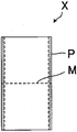
본 발명에 따른 잉크젯 프린터는 페이지 단락마다 미싱눈(M)이 설치되고, 양측에 마지널 펀치(P)가 설치된 장척상의 연속 용지(X)(도 8 참조)에 대하여, 잉크젯 방식으로 인자하기 위한 장치이다.The inkjet printer according to the present invention is an inkjet printer according to the present invention for printing on continuous continuous paper X (see Fig. 8) of long continuous paper on which the machine eyes M are provided for every page and the margin punches P are provided on both sides, Device.
우선, 본 발명에 따른 잉크젯 프린터의 하나의 실시형태에 대해서 설명한다.First, one embodiment of the ink-jet printer according to the present invention will be described.
도 1은 본 실시형태에 따른 잉크젯 프린터의 개략을 나타내는 정면도이다.1 is a front view schematically showing an inkjet printer according to the present embodiment.
도 1에 나타내는 바와 같이, 본 실시형태에 따른 잉크젯 프린터(100)는 Z형으로 접힌 연속 용지(X)를 배치하는 급지부(1)와, 연속 용지(X)를 안내함과 동시에 텐션을 부여하기 위한 백 텐션 롤러군(8)과, 이 연속 용지(X)를 반송하기 위한 제1 풀 롤러(2a) 및 제2 풀 롤러(2b)와, 이 연속 용지(X)의 위치 결정을 하기 위한 핀 트랙터(3)와, 이 연속 용지(X)에 텐션을 부가하기 위한 속도 가변 모터(4)와, 이 연속 용지(X)에 인자 헤드(도시하지 않음)로 인자하는 인자부(5)와, 인자된 연속 용지(X)를 건조시키기 위한 건조부(7)와, 이 연속 용지(X)를 접지기(61)로 Z형으로 접어 배출하는 배출부(6)와, 이들을 내장하고 또한 보호하기 위한 하우징(H)을 구비한다.1, the
이하, 각 구성에 대해서 더욱 상세하게 설명한다.Hereinafter, each configuration will be described in more detail.
급지부(1)는 Z형으로 접힌 연속 용지(X)가 배치되는 부위이다.The
또한, 급지부(1)는 하우징(H) 내에 설치되어 있는데, 이것에 한정되지 않고, 하우징(H) 밖에 설치되어 있어도 된다.The
백 텐션 롤러군(8)은 복수의 롤러(8a)로 이루어지고, 급지부(1)와 핀 트랙터(3) 사이에 배치된다.The back
그리고, 백 텐션 롤러군(8) 중 적어도 1개의 롤러(8a)에는 BT용 속도 가변 모터(도시하지 않음)가 부착되어 있다.A BT variable speed motor (not shown) is attached to at least one
또한, 당해 BT용 속도 가변 모터로서는 서보 기구에 있어서 속도 등을 제어 가능한 서보 모터나, 그 이외의 전동기에 차동 변속기를 탑재한 것 등을 들 수 있다.The BT variable speed motor may be a servomotor capable of controlling the speed or the like in a servo mechanism or a motor having a differential transmission mounted in the other motor.
백 텐션 롤러군(8)에 있어서는, 연속 용지(X)를 안내할 때에 텐션을 부여할 수 있다. 즉, BT용 속도 가변 모터가 후술하는 제1 풀 롤러(2a) 또는 제2 풀 롤러(2b)의 회전 속도에 대하여, 롤러(8a)의 회전 속도를 변화시킴으로써 연속 용지(X)에 텐션을 부여하고, 또한 텐션을 조정하는 것이 가능하게 되어 있다. 이 때문에 급지부(1)와 핀 트랙터(3) 사이의 연속 용지(X)에도 텐션이 부여되는 점에서, 연속 용지의 반송 중에 있어서, 핀 트랙터(3)의 핀을 연속 용지(X)의 마지널 펀치(P)에 정확하고 또한 확실하게 삽입할 수 있다.In the back
그 결과, 연속 용지에 대한 핀 트랙터(3)의 추종 불량을 방지할 수 있다.As a result, it is possible to prevent the follow-up failure of the
핀 트랙터(3)는 연속 용지(X)의 양측에 설치된 마지널 펀치(P)에 각각 대응하도록 한 쌍 설치되어 있다. 또한, 한 쌍의 핀 트랙터(3)는 서로 동기하여 움직이도록 되어 있다.The pair of
핀 트랙터(3)는 공지의 것과 동일한 구조이며, 마지널 펀치(P)에 걸어맞추는 핀과, 핀이 붙은 핀 벨트를 반송 방향으로 구동시키는 구동 스프로킷(32a)을 가지고 있다.The
따라서, 핀 트랙터(3)는 연속 용지(X)의 양측에 설치된 마지널 펀치(P)에 각핀 트랙터(3)의 핀을 삽입함으로써, 연속 용지(X)의 위치 결정을 할 수 있다.Therefore, the
여기서, 핀 트랙터(3)의 연속 용지(X)를 통하여 대향하는 측에는, 기준 검출 센서(31)가 부착되어 있다.Here, a
당해 기준 검출 센서(31)는 예를 들면 연속 용지(X)의 전단을 검출함으로써 기준을 설정할 수 있다.The
또, 핀 트랙터(3)에 연속 용지(X)를 위치 결정하여 부착했을 때에, 연속 용지(X)의 전단이 이미 기준 검출 센서(31)를 통과하고 있는 경우는, 기준 검출 센서(31)가 연속 용지(X)의 전단을 검출할 수 없기 때문에, 연속 용지(X)를 백 피드한 후, 연속 용지(X)를 전진시켜, 기준 검출 센서(31)로 연속 용지(X)의 전단을 검출하면 된다. 또한, 기준으로 하는 것은 연속 용지(X)의 전단에 한정되지 않고, 임의의 위치여도 된다.If the front end of the continuous sheet X has already passed through the
또, 적어도 일방의 기준 검출 센서(31)가 부착된 핀 트랙터(3)의 구동 스프로킷(32a)에는 핀 트랙터 인코더(32)가 부착되어 있다.A
당해 핀 트랙터 인코더(32)는 핀 트랙터(3)의 이동량을 측정하도록 되어 있다.The
이러한 점들에 의해, 기준 검출 센서(31)가 검출한 특정의 위치를 기준으로 하고, 핀 트랙터 인코더(32)가 핀 트랙터(3)의 이동량을 측정함으로써, 반송되는 연속 용지(X)의 위치 정보를 인식하는 것이 가능하게 된다.With these points, the
이것에 의해, 상기 위치 정보에 기초하여 적절한 위치가 인자부(5)에 도달한 단계에서 인자를 개시할 수 있다. 또한, 이러한 인자 방법의 상세에 대해서는 후술한다.As a result, the printing can be started at a position where the appropriate position reaches the
잉크젯 프린터(100)에 있어서, 제1 풀 롤러(2a) 및 제2 풀 롤러(2b)에는 각각 연속 용지(X)를 협지하기 위한 누름 롤러가 맞닿아 있다.In the
또, 제1 풀 롤러(2a)에는 구동 모터(도시하지 않음)가 부착되어 있고, 제2 풀 롤러(2b)에는 속도 가변 모터(4)가 부착되어 있다.A drive motor (not shown) is attached to the first
따라서, 제1 풀 롤러(2a)와 대응하는 누름 롤러 사이에서 연속 용지(X)를 협지하고, 구동 모터에 의해 제1 풀 롤러(2a)를 구동시키고, 제2 풀 롤러(2b)와 대응하는 누름 롤러 사이에서 연속 용지(X)를 협지하고, 속도 가변 모터(4)에 의해 제2 풀 롤러(2b)를 구동시킴으로써, 당해 연속 용지(X)를 반송하는 것이 가능하게 되어 있다.Therefore, the continuous paper X is sandwiched between the first
또한, 당해 속도 가변 모터(4)로서는 서보 기구에 있어서 속도 등을 제어 가능한 서보 모터나, 그 이외의 전동기에 차동 변속기를 탑재한 것 등을 들 수 있다.The
제2 풀 롤러(2b)에 있어서는, 속도 가변 모터(4)가 제1 풀 롤러(2a)의 회전 속도에 대하여 제2 풀 롤러(2b)의 회전 속도를 변화시킴으로써 연속 용지(X)에 텐션을 부여하고 또한 텐션을 조정하는 것이 가능하게 되어 있다. 이 때문에, 제1 풀 롤러(2a)와 제2 풀 롤러(2b) 사이의 연속 용지(X)에도 텐션이 부여되는 점에서, 특히 인자부(5)에 있어서 연속 용지(X)의 미싱눈의 위치가 접히는 경향에 의한 산형상 또는 곡형상의 기복이 발생하는 것을 방지할 수 있다.In the second
또, 인자시에 있어서는, 인자의 어긋남이나 인자의 품질도 악화를 방지할 수 있고, 인자 헤드가 연속 용지(X)와 접촉하는 것도 방지할 수 있다.In addition, at the time of printing, it is possible to prevent deterioration in the quality of the printing quality and print quality, and it is also possible to prevent the print head from coming into contact with the continuous paper (X).
또한, 페이지 단락마다 미싱눈이 설치된 용지는 텐션을 지나치게 걸면, 그 미싱눈에서 파단할 우려가 있기 때문에, 제2 풀 롤러의 회전 속도를 제1 풀 롤러의 회전 속도보다 빠르게 하는 비율은 최대 약0.05% 증가로 즉 당기는 비율로 플러스 약0.05%까지인 것이 바람직하다.In addition, since the paper provided with the sewing eyes per page is excessively tensioned, there is a risk of breaking at the sewing eyes. Therefore, the ratio of the rotation speed of the second full rollers to the rotation speed of the first full rollers is about 0.05 %, I.e. at a rate of pulling plus up to about 0.05%.
인자부(5)에 있어서는, 인자 헤드(도시하지 않음)를 내장하고 있어, 이 인자 헤드에 의해 연속 용지(X)에 인자가 행해진다.In the
당해 인자 헤드로서는 시리얼 헤드나 라인 헤드 등이 채용 가능한데, 고속 인자의 관점에서 라인 헤드를 채용하는 것이 바람직하다.A serial head, a line head, or the like can be employed as the print head, but it is preferable to adopt a line head from the viewpoint of high speed printing.
건조부(7)는 인자된 연속 용지(X)를 건조시키는 부위이다.The
건조부(7)는 인자된 연속 용지(X)를 배출 전에 건조시킬 수 있으므로, 배출 후 소정의 페이지에 인자된 사항이 다른 페이지에 찍히는 것을 방지할 수 있다.The drying
또, 연속 용지의 반송 경로에 있어서, 건조부(7)는 인자부(5)와 제2 풀 롤러(2b) 사이에 설치되어 있으므로, 연속 용지(X)에 텐션이 부여된 상태로 되어 있다. 이 때문에, 연속 용지(X)를 균일하게 건조하는 것이 가능하게 된다.Since the
배지부(6)는 인자된 연속 용지(X)를 접지기(61)로 Z형으로 접어 배출하는 부위이다.The
또한, 배지부(6)는 하우징(H) 내에 설치되어 있지만, 이것에 한정되지 않고, 하우징(H) 밖에 설치되어 있어도 된다.Further, although the
본 실시형태에 따른 잉크젯 프린터(100)에 있어서는, 연속 용지(X)의 반송 경로의 상류측으로부터 급지부(1), 백 텐션 롤러군(8), 핀 트랙터(3), 제1 풀 롤러(2a), 인자부(5), 건조부(7), 제2 풀 롤러(2b), 배지부(6)의 순서로 배치되어 있으므로, 연속 용지(X)의 반송 경로 전반에 걸쳐 적절한 텐션을 부여하는 것이 가능하게 된다. 특히, 인자부에 있어서는, 충분한 텐션을 부여하는 것이 가능하게 된다.The
구체적으로는 연속 용지(X)의 두께나 재질에 따라, 제2 풀 롤러의 회전 속도를 제1 풀 롤러의 회전 속도보다 빠르게 하는 비율을 바꾸어 적절한 텐션을 부여하는 것이 가능하게 된다. 일반적으로 상기 비율은 얇은 종이보다 두꺼운 종이 쪽이 높아진다.More specifically, depending on the thickness and material of the continuous sheet X, it is possible to change the ratio of rotating the second full roller to the rotational speed of the first full roller to give appropriate tension. Generally, the ratio is higher for thinner paper than for thicker paper.
다음에, 본 실시형태에 따른 잉크젯 프린터(100)를 사용한 인자 방법에 대해 설명한다.Next, a printing method using the
도 2는 본 실시형태에 따른 잉크젯 프린터를 사용한 인자 방법을 나타내는 플로우차트이다.2 is a flowchart showing a printing method using the inkjet printer according to the embodiment.
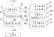
도 2에 나타내는 바와 같이, 잉크젯 프린터를 사용한 인자 방법에 있어서는, 우선 기준 검출 센서(31)로 연속 용지(X)의 전단을 검출하기 전, 즉 용지 통과 전에 1페이지의 인쇄 길이를 발신기(9)에 설정한다.2, in the printing method using the ink jet printer, the printing length of one page is detected before the front end of the continuous paper X is detected by the
다음에, 인자 개시의 스타트 버튼을 누르면, 반송 지령부(91)(예를 들면 모션 컨트롤)가 제1 풀 롤러(2a) 및 제2 풀 롤러(2b)에 반송 지령(M1)을 발신한다. 이것에 의해, 연속 용지(X)의 반송이 개시된다.Next, when the start button of the start of printing is pressed, the conveyance command section 91 (for example, motion control) sends the conveyance command M1 to the
또, 반송 지령부(91)로부터 전용 모터(M1-1)에도 반송 지령(M1')이 발신되고, 전용 모터(M1-1)가 TACH용 인코더(40)를 회전시킨다. 또한, TACH용 인코더(40)는 제1 풀 롤러(2a) 또는 제2 풀 롤러(2b)와 동기되어 있다.The
그리고, TACH용 인코더(40)는 TACH용 인코더로부터 발진되는 TACH 펄스(M5)를 위치 정보 연산부(92)에 발신한다.Then, the
다음에, 기준 검출 센서(31)가 검출한 용지의 특정의 위치를 기준으로 하고, 그 기준값(M2)이 발신기(9)에 보내진다.Next, the reference value M2 is sent to the
또, 연속 용지(X)의 반송에 의해 핀 트랙터(3)가 구동하기 때문에, 당해 핀 트랙터(3)의 이동량에 비례하여 출력되는 핀 트랙터 인코더(32)의 펄스(M3)가 발신기(9)에 보내진다.Since the
그렇게 하면, 발신기(9)의 위치 정보 연산부(92)는 TACH 펄스(M5)와, 기준값(M2)과, 펄스(M3)를 카운트함으로써 얻어지는 검출값과, 미리 발신기(9)에 설정된 1페이지의 인쇄 길이의 정보에 기초하여 위치 정보를 연산하여 인자 개시 타이밍을 만들고, 인자부(5)에 인자 지령(M4)을 발신한다.The
다음에, 발신기(9)의 딜레이값 연산부(93)가 미리 설정된 연속 용지(X)의 미싱눈(M)으로부터 실제로 인자를 개시하고자 하는 위치까지의 거리를 연속 용지(X)가 반송되기에 필요한 시간(딜레이값)을 산출한다.Next, the
그리고, 그 딜레이값을 인자 개시 타이밍에 부가함으로써, 인자 지령의 발신을 늦춘 인자 지령(M4')을 발신한다.Then, by adding the delay value to the print start timing, an argument command (M4 ') for delaying the transmission of the print command is issued.
도 3은 본 실시형태에 따른 잉크젯 프린터를 사용한 인자 방법에 있어서의 딜레이값을 설명하기 위한 그래프이다. 도 3에 있어서, (1)의 그래프는 인자 개시의 스타트 버튼의 ON/OFF를 나타내고, (2)의 그래프는 발신기(9)가 발신하는 인자 지령(M4)의 ON/OFF를 나타내며, (3)의 그래프는 실제의 인자 개시 위치의 ON/OFF를 나타내고, (4)의 그래프는 연속 용지(X)의 반송 속도를 나타낸다.3 is a graph for explaining the delay value in the printing method using the ink jet printer according to the present embodiment. 3, the graph of (1) shows ON / OFF of the start button of the start of printing, the graph of (2) shows ON / OFF of the printing command M4 of the
도 3에 나타내는 바와 같이, 발신기(9)가 발신하는 인자 지령(M4)(ON)의 타이밍과, 실제의 인자 개시 위치(ON)의 타이밍은 일치하지 않아, 시간적인 어긋남이 발생하고 있다.As shown in Fig. 3, the timing of the print command M4 (ON) generated by the
구체적으로는 예를 들면 발신기(9)가 발신하는 최초의 인자 지령(CUE-1)과, 최초의 인자 개시 위치(CUE-P)의 타이밍에는 차가 있다.Concretely, for example, there is a difference between the timing of the first print command (CUE-1) sent from the
이 타이밍의 차가 딜레이값이 된다.The difference between these timings becomes a delay value.
딜레이값 연산부(93)는 미리 설정된 이 딜레이값의 분만큼 인자 지령을 늦추게 된다.The
또한, 딜레이값은 미리 설정되는 미싱눈으로부터 실제의 인자의 위치까지의 거리에 따라 바뀐다.Also, the delay value changes depending on the distance from the preset sewing eye to the position of the actual factor.
또, 속도가 일정한 경우는 딜레이값은 변화하지 않고, 속도가 변화하는 경우는 그것에 따라 바뀐다. 또, 딜레이값의 구체적인 값은 경험칙에 기초하여 설정된다.When the speed is constant, the delay value does not change, and when the speed changes, the delay value changes accordingly. The specific value of the delay value is set based on the empirical rule.
이것에 의해, 미싱눈으로부터가 아니라, 실제의 인자의 위치로부터 인자하는 것이 가능하게 된다.As a result, it is possible to print from the position of the actual factor, not from the sewing machine.
또, 발신기(9)가 발신하는 인자 지령(M4)과 실제의 인자 개시 위치 사이에 연속 용지(X)의 반송 속도에 기초하는 어긋남이 있거나, 노즐 헤드와 대향하는 연속 용지(X)까지의 거리에 따른 착탄 시간의 차가 있는 경우에도, 이들을 포함하여 상기 딜레이값을 조정함으로써, 적절한 인자 개시 위치가 되도록 적당히 수정할 수 있다.If there is a shift based on the conveyance speed of the continuous sheet X between the print command M4 issued by the
그리고, 수정된 타이밍에 인자 지령(M4')을 받은 인자 헤드가 연속 용지(X)에 인자를 행한다.Then, the print head receiving the print command M4 'at the corrected timing prints the continuous paper X.
이와 같이 잉크젯 프린터를 사용한 인자 방법에 있어서는, 간단한 처리 플로우로 인자를 행할 수 있다. 이 때문에 연속 용지(X)를 고속 반송한 경우에도, 그것에 추종하여 인자를 행하는 것이 가능하게 된다.As described above, in the printing method using the ink jet printer, printing can be performed with a simple processing flow. Therefore, even when the continuous paper X is conveyed at a high speed, printing can be performed following the same.
잉크젯 프린터를 사용한 인자 방법에 있어서는, 연속 용지(X)의 반송 속도가 가속 또는 감속되고 있는 상태여도 인자가 가능하게 되어 있다.In the printing method using the ink jet printer, printing can be performed even when the conveying speed of the continuous sheet X is accelerated or decelerated.
도 4는 본 실시형태에 따른 잉크젯 프린터를 사용한 인자 방법에 있어서 연속 용지가 가속된 예를 나타내는 그래프이다. 도 4에 있어서, (1)의 그래프는 인자 지령의 ON/OFF를 나타내고, (2)의 그래프는 인자 헤드의 UP/DOWN을 나타내며, (3)의 그래프는 연속 용지(X)의 반송 속도를 나타낸다.4 is a graph showing an example in which continuous paper is accelerated in the printing method using the inkjet printer according to the present embodiment. 4, the graph of (1) represents ON / OFF of the print command, the graph of (2) represents UP / DOWN of the print head, and the graph of (3) .
도 4에 나타내는 바와 같이, 인자 지령이 ON이 되면, 인자 헤드가 DOWN하고, 인자의 스탠바이 상태가 된다.As shown in Fig. 4, when the print command is turned ON, the print head goes down and the print standby state is established.
그리고, 인자가 개시됨과 동시에, 연속 용지(X)의 반송 속도가 0m/min로부터 10m/min로 가속되고, 건조기의 온도가 일정하게 될 때까지, 일단 10m/min의 정속이 되고, 그 후 10m/min로부터 80m/min로 가속된다.Then, at the same time as the printing was started, the conveying speed of the continuous sheet X was accelerated from 0 m / min to 10 m / min, and the constant speed of 10 m / min was once reached until the temperature of the dryer became constant, / min to 80 m / min.
즉, 연속 용지(X)의 반송 속도가 정속인 경우 뿐만아니라 가속되는 경우에도 연속하여 인자가 행해진다.That is, printing is continuously performed not only when the conveying speed of the continuous sheet X is constant but also when it is accelerated.
또한, 도시하고 있지 않지만, 연속 용지(X)가 감속되는 경우에도 연속하여 인자가 행해진다.Although not shown, printing is continuously performed even when the continuous sheet X is decelerated.
여기서, 상기 인자 방법에 있어서는, 연속 용지의 반송 속도가 감속된 경우에는 감속되기 직전의 해상도로 기록하고, 용지의 반송 속도가 가속된 경우에는 가속된 직후의 해상도로 기록한다.Here, in the printing method, when the conveying speed of the continuous paper is reduced, the printing is performed at the resolution just before the deceleration, and when the conveying speed of the paper is accelerated, the printing is performed at the resolution immediately after the acceleration.
예를 들면, 감속시에 있어서는, 연속 용지(X)의 반송 속도를 단순히 감속시키면 해상도가 서서히 높아지는 점에서, 연속 용지(X)의 반송 속도를 감속시킴과 아울러, 인자 헤드가 잉크를 토출하는 타이밍을 늦춤으로써 저해상도를 유지시킨다.For example, at the time of deceleration, the conveyance speed of the continuous sheet X is decelerated because the resolution is gradually increased by simply decelerating the conveying speed of the continuous sheet X, and the timing at which the print head discharges ink To maintain the low resolution.
가속시에 있어서는, 연속 용지(X)의 반송 속도를 단순히 가속시키면 해상도가 서서히 낮아지는 점에서, 연속 용지(X)의 반송 속도를 가속시킴과 아울러, 인자 헤드가 잉크를 토출하는 타이밍을 빠르게 함으로써 저해상도를 유지시킨다.At the time of acceleration, since the resolution is gradually lowered by merely accelerating the conveyance speed of the continuous sheet X, the conveyance speed of the continuous sheet X is accelerated and the timing at which the print head ejects ink is accelerated Maintain low resolution.
이것에 의해, 연속 용지(X)의 가감속시여도 연속하여 인자하는 것이 가능하게 되고, 또한 인자가 흐릿해지거나 샤프함이 결여되거나 하는 것을 억제할 수 있다.This makes it possible to continuously print even when the continuous paper X is accelerated or decelerated, and it is possible to suppress the blurring of the printing or the lack of sharpness.
다음에, 백 피드 기능에 의한 인자 방법에 대해 설명한다.Next, a method of printing by the backfeed function will be described.
본 실시형태에 따른 잉크젯 프린터(100)는 연속 용지(X)를 역방향으로 반송시키는 소위 백 피드 기능을 가지고 있다.The ink-
도 5의 (a)~(c)는 본 실시형태에 따른 잉크젯 프린터의 백 피드 기능을 이용한 인자 방법을 설명하기 위한 설명도이다.5A to 5C are explanatory diagrams for explaining a printing method using the backfeed function of the inkjet printer according to the present embodiment.
예를 들면, 인자를 도중에 정지시키고, 그 후 용지의 반송을 정지시킨 경우, 용지가 고속으로 반송되고 있기 때문에, 도 5의 (a)에 나타내는 바와 같이 연속 용지(X)의 인자하고 있지 않은 페이지가 인자부(5)를 통과하여, 백지 부분이 매우 많이 발생한다.For example, when the printing is stopped halfway and the conveyance of the sheet is stopped, the sheet is conveyed at a high speed. Therefore, as shown in Fig. 5A, Passes through the
이 경우, 상기 서술한 핀 트랙터 인코더(32)의 검출값에 기초하여 인자하고있지 않은 최초의 페이지로부터 인자 개시 가능하게 되도록, 적어도 제1 풀 롤러(2a) 및 제2 풀 롤러(2b)를 역방향으로 회전시킴으로써, 도 5의 (b)에 나타내는 바와 같이 연속 용지(X)를 반송 방향과는 역방향으로 반송하고, 적어도 백지 부분의 선두 페이지의 하류측이 인자부(5)의 상류측에 오면 정지한다.In this case, based on the detection value of the
그리고, 상기 서술한 인자 방법과 마찬가지로, 발신기(9)가 반송 지령(M1)을 발신하고, 연속 용지(X)가 다시 순방향으로 반송되고, 기준값(M2)과 검출값에 기초하여 인자 지령(M4)을 발신하고, 딜레이값의 분만큼 늦추어 인자가 개시된다.Then, in the same manner as the above-described printing method, the
이 때, 도 5의 (c)에 나타내는 바와 같이, 인자 개시 위치가 인자부(5)를 통과한 백지 부분(인자하고 있지 않은 페이지)으로부터 인자를 시작하도록 함으로써, 용지의 낭비를 없앨 수 있다.At this time, as shown in Fig. 5 (c), printing is started from a blank portion (a page that has not been printed) in which the printing start position has passed through the
다음에, 본 발명에 따른 자동 용지 통과 방법에 대해서 설명한다.Next, an automatic paper passing method according to the present invention will be described.
도 6은 본 실시형태에 따른 자동 용지 통과 방법에 사용되는 잉크젯 프린터의 개략을 나타내는 모식도이다.6 is a schematic diagram showing an outline of an inkjet printer used in the automatic paper passing method according to the present embodiment.
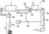
도 6에 나타내는 바와 같이, 본 실시형태에 따른 자동 용지 통과 방법에 사용되는 잉크젯 프린터(101)는 Z형으로 접힌 연속 용지(X)를 배치하는 급지부(도시하지 않음)와, 이 연속 용지(X)를 반송하기 위한 제1 풀 롤러(2a), 중간 풀 롤러(2c) 및 제2 풀 롤러(2b)와, 이 연속 용지(X)의 위치 결정을 하기 위한 제1 핀 트랙터(3a) 및 제2 핀 트랙터(3b)와, 이 연속 용지(X)에 인자 헤드(도시하지 않음)로 인자하는 인자부(5)와, 인자된 연속 용지(X)를 건조시키기 위한 건조부(7)와, 이 연속 용지(X)를 접지기(61)로 Z형으로 접어 배출하는 배출부(6)와, 이들을 내장하고 또한 보호하기 위한 하우징(도시하지 않음)을 구비한다.6, the
이하, 각 구성에 대해서 더욱 상세하게 설명한다.Hereinafter, each configuration will be described in more detail.
급지부(1)는 Z형으로 접힌 연속 용지(X)가 배치되는 부위이다.The
또한, 급지부(1)는 하우징 내에 설치되어 있어도 되고, 하우징 밖에 설치되어 있어도 된다.Further, the
제1 핀 트랙터(3a)는 연속 용지(X)의 양측에 설치된 마지널 펀치(P)에 각각 대응하도록 한 쌍 설치되어 있다. 또한, 한 쌍의 제1 핀 트랙터(3a)는 서로 동기하여 움직이도록 되어 있다.The pair of
또, 제2 핀 트랙터(3b)도 마찬가지의 구조로 되어 있다.The
제1 핀 트랙터(3a) 및 제2 핀 트랙터(3b)는 각각 공지의 것과 동일한 구조이며, 마지널 펀치(P)에 걸어맞추는 핀과, 핀이 붙은 핀 벨트를 반송 방향으로 구동시키는 구동 스프로킷(32a)을 가지고 있다.The
따라서, 제1 핀 트랙터(3a) 및 제2 핀 트랙터(3b)는 연속 용지(X)의 양측에 설치된 마지널 펀치(P)에 제1 핀 트랙터(3a) 및 제2 핀 트랙터(3b)의 핀을 삽입함으로써, 연속 용지(X)의 위치 결정을 할 수 있다.The
또, 제1 핀 트랙터(3a)에는 클러치(33)를 통하여 구동 모터(34)가 부착되고, 제2 핀 트랙터에는 구동 모터(34)가 직접 부착되어 있다. 즉, 구동 모터(34)에 의해 제1 핀 트랙터(3a) 및 제2 핀 트랙터(3b)가 구동하도록 되어 있다.A
또한, 제2 핀 트랙터(3b)는 핀을 마지널 펀치에 삽입한 상태로부터 핀을 마지널 펀치로부터 발거한 상태가 되도록, 도시하지 않는 승강 구동 장치에 의해 상하 방향으로 이동 가능하게 되어 있다.The
여기서, 제2 핀 트랙터(3b)의 연속 용지(X)를 통하여 대향하는 측에는 용지검출 센서(35)가 부착되어 있다.Here, a
당해 용지 검출 센서(35)는 예를 들면 연속 용지(X)의 전단을 검출함으로써, 연속 용지(X)의 유무를 판단하는 것이 가능하게 되어 있다.The
잉크젯 프린터(101)에 있어서, 제1 풀 롤러(2a), 중간 풀 롤러(2c) 및 제2 풀 롤러(2b)에는 각각 연속 용지(X)를 협지하기 위한 누름 롤러가 맞닿아 있다.In the
여기서, 당해 누름 롤러에는 각각 에어 실린더 등의 구동 장치가 부착되어 있고, 당해 구동 장치에 의해 대응하는 풀 롤러에 대하여 착탈이 자유롭게 되어 있다.Here, driving rollers such as air cylinders are attached to the pressing rollers, respectively, and the driving rollers are freely attachable and detachable to the corresponding pull rollers.
또, 제1 풀 롤러(2a), 중간 풀 롤러(2c) 및 제2 풀 롤러(2b)에는 각각 구동 모터(도시하지 않음)가 부착되어 있다.A drive motor (not shown) is attached to each of the
따라서, 제1 풀 롤러(2a)와 대응하는 누름 롤러 사이에서 연속 용지(X)를 협지하고, 구동 모터에 의해 제1 풀 롤러(2a)를 구동시키고, 제2 풀 롤러(2b)와 대응하는 누름 롤러 사이에서 연속 용지(X)를 협지하고, 구동 모터에 의해 제2 풀 롤러(2b)를 구동시킴으로써, 당해 연속 용지(X)를 반송하는 것이 가능하게 되어 있다.Therefore, the continuous paper X is sandwiched between the first
인자부(5)에 있어서는, 인자 헤드(도시하지 않음)를 내장하고 있어, 이 인자 헤드에 의해 연속 용지(X)에 인자가 행해진다.In the
당해 인자 헤드로서는 시리얼 헤드나 라인 헤드 등이 채용 가능한데, 고속 인자의 관점에서 라인 헤드를 채용하는 것이 바람직하다.A serial head, a line head, or the like can be employed as the print head, but it is preferable to adopt a line head from the viewpoint of high speed printing.
건조부(7)는 인자된 연속 용지(X)를 건조시키는 부위이다.The
건조부(7)는 인자된 연속 용지(X)를 배출 전에 건조시킬 수 있으므로, 배출 후 소정의 페이지에 인자된 사항이 다른 페이지에 찍히는 것을 방지할 수 있다.The drying
또, 연속 용지의 반송 경로에 있어서, 건조부(7)는 인자부(5)와 제2 풀 롤러(2b) 사이에 설치되어 있으므로, 연속 용지(X)를 텐션이 부여된 상태로 함으로써, 연속 용지(X)를 균일하게 건조시키는 것이 가능하게 된다.Since the
배지부(6)는 인자된 연속 용지(X)를 접지기(61)로 Z형으로 접어 배출하는 부위이다.The
또한, 배지부(6)는 하우징 내에 설치되어 있어도 되고, 하우징 밖에 설치되어 있어도 된다.Further, the
잉크젯 프린터(101)에 있어서는, 연속 용지(X)의 반송 경로의 상류측으로부터 급지부(1), 제1 핀 트랙터(3a), 제1 풀 롤러(2a), 인자부(5), 중간 풀 롤러(2c), 제2 핀 트랙터(3b), 건조부(7), 제2 풀 롤러(2b), 배지부(6)의 순서로 배치되어 있으므로, 후술하는 자동 용지 통과를 효율적으로 행할 수 있다.In the
다음에, 본 실시형태에 따른 자동 용지 통과 방법에 대해서 설명한다.Next, an automatic paper passing method according to the present embodiment will be described.
도 7은 본 실시형태에 따른 자동 용지 통과 방법을 나타내는 플로우차트이다.7 is a flowchart showing an automatic paper passing method according to the present embodiment.
도 7에 나타내는 바와 같이, 본 실시형태에 따른 자동 용지 통과 방법은 이하에 설명하는 제1 스텝(S1), 제2 스텝(S2), 제3 스텝(S3), 제4 스텝(S4), 제5 스텝(S5), 제6 스텝(S6) 및 제7 스텝(S7)으로 이루어진다.As shown in Fig. 7, the automatic paper passing method according to the present embodiment includes a first step S1, a second step S2, a third step S3, a fourth step S4, Five steps (S5), a sixth step (S6), and a seventh step (S7).
제1 스텝(S1)에 있어서는, 제1 핀 트랙터(3a)의 핀을 연속 용지(X)의 전단의 마지널 펀치(P)에 삽입한다.In the first step (S1), the pin of the first pin tractor (3a) is inserted into the last punch (P) of the preceding sheet of continuous paper (X).
또한, 이러한 제1 스텝(S1)은 작업자가 행한다.The first step (S1) is performed by the operator.
이것에 의해, 연속 용지(X)의 위치 결정이 이루어진다.As a result, the continuous sheet X is positioned.
제2 스텝(S2)에 있어서는, 클러치(33)를 연결시키고, 제1 핀 트랙터(3a)를 구동 모터(34)에 의해 구동시켜, 연속 용지(X)를 반송한다.In the second step S2, the clutch 33 is connected, the
이 때, 연속 용지(X)의 전단은 누름 롤러가 맞닿아 있지 않은 제1 풀 롤러(2a)와, 인자부(5)와, 누름 롤러가 맞닿아 있지 않은 중간 풀 롤러(2c)를 통과한다.At this time, the front end of the continuous sheet X passes through the first
그리고, 용지 검출 센서(35)가 연속 용지(X)의 전단을 검출할 때까지 연속 용지(X)를 반송한 후, 구동 모터(34)에 의한 제1 핀 트랙터(3a)의 구동을 정지시킨다.The continuous paper X is conveyed until the
제3 스텝(S3)에 있어서는, 이탈되어 있던 누름 롤러를 중간 풀 롤러(2c)에 맞닿게 하고, 이 중간 풀 롤러(2c)와 누름 롤러 사이에서 연속 용지(X)를 협지한다.In the third step S3, the released pushing roller is brought into contact with the
그리고, 중간 풀 롤러(2c)가 연속 용지(X)를 미속도로 하류측으로 반송한다. 이 때, 제1 핀 트랙터(3a)는 구동이 정지되어 있지만, 클러치(33)는 연결되어 있으므로, 중간 풀 롤러(2c)가 미속도로 상류측으로 연속 용지(X)를 반송함으로써, 연속 용지(X)에 텐션이 부여된다. 이것에 의해, 중간 풀 롤러(2c)로부터 제1 핀 트랙터(3a)까지의 사이 예를 들면 인자부(5)의 연속 용지(X)는 텐션이 부여된 상태가 된다. 이 때, 중간 풀 롤러(2c)에 맞닿게 한 누름 롤러의 맞닿음 압력을 조정하여, 중간 풀 롤러(2c)가 연속 용지(X)를 지나치게 끌어내지 않도록 슬립시킨다.Then, the
제4 스텝(S4)에 있어서는, 제2 핀 트랙터(3b)의 핀을 연속 용지(X)의 마지널 펀치(P)에 삽입한다.In the fourth step S4, the pin of the
즉, 상기 제3 스텝(S3)에 있어서, 제2 핀 트랙터(3b)의 핀과 연속 용지(X)의 마지널 펀치(P)와의 위치가 일치하도록, 중간 풀 롤러(2c)가 미속도로 상류측으로 연속 용지(X)를 반송한다.That is, in the third step (S3), the
그리고, 제2 핀 트랙터(3b)의 핀과 연속 용지(X)의 마지널 펀치(P)와의 위치가 일치되었을 때에, 제2 핀 트랙터(3b)를 승강 구동 장치에 의해 상승 이동시키고, 제2 핀 트랙터(3b)의 핀을 연속 용지(X)의 마지널 펀치(P)에 삽입한다.When the pin of the
제5 스텝(S5)에 있어서는, 클러치(33)를 끊음으로써 제1 핀 트랙터(3a)를 자유 회전 가능한 상태로 하고, 연속 용지(X)의 반송에 종동시킨다.In the fifth step S5, the
그리고, 적어도 제2 핀 트랙터(3b)를 구동 모터(34)에 의해 구동시켜, 연속 용지(X)를 건조부(7), 배출부(6)까지 반송한다.At least the
이 때, 연속 용지(X)의 전단은 건조부(7)와, 누름 롤러가 맞닿아 있지 않은 제2 풀 롤러(2b)를 통과한다.At this time, the front end of the continuous sheet X passes through the drying
그리고, 연속 용지(X)를 배출부(6)까지 반송한 후, 구동 모터(34)에 의한 제2 핀 트랙터(3b)의 구동을 정지시킨다.After the continuous sheet X is conveyed to the
제6 스텝(S6)에 있어서는, 핀을 마지널 펀치(P)로부터 발거하기 위해서 제2 핀 트랙터(3b)를 승강 구동 장치에 의해 하강 이동시킨다. 또한, 자유 회전 가능하게 되어 있는 제1 핀 트랙터(3a)는 핀을 마지널 펀치(P)에 삽입한 상태에서 유지된다.In the sixth step (S6), the second pin tractor (3b) is moved down by the elevation drive device in order to eject the pin from the last punch (P). Further, the
제7 스텝(S7)에 있어서는, 제1 풀 롤러(2a)에 대응하는 누름 롤러를 구동 장치를 사용하여 제1 풀 롤러(2a)에 맞닿게 하고, 제2 풀 롤러(2b)에 대응하는 누름 롤러를 구동 장치를 사용하여 제2 풀 롤러(2b)에 맞닿게 한다.In the seventh step S7, the pressing roller corresponding to the first
이것에 의해, 연속 용지(X)는 제1 풀 롤러(2a)와 이 제1 풀 롤러(2a)에 맞닿은 누름 롤러와의 사이, 및 제2 풀 롤러(2b)와 이 제2 풀 롤러(2b)에 맞닿은 누름 롤러와의 사이에서 협지된다.The continuous paper X is conveyed between the first
그리고, 구동 모터에 의해 제1 풀 롤러(2a) 및 제2 풀 롤러(2b)를 각각 구동시킴으로써, 자동 용지 통과가 행해진 연속 용지(X)의 반송이 가능하게 된다.By driving the
본 실시형태에 따른 자동 용지 통과 방법에 있어서는, 제1 스텝(S1), 제2 스텝(S2), 제3 스텝(S3), 제4 스텝(S4), 제5 스텝(S5), 제6 스텝(S6) 및 제7 스텝(S7)을 행함으로써, 도중에 막하지 않고 원활하게 자동으로 용지 통과를 행할 수 있다.In the automatic paper passing method according to the present embodiment, the first step S1, the second step S2, the third step S3, the fourth step S4, the fifth step S5, (Step S6) and the seventh step (step S7), it is possible to smoothly and automatically pass the sheet without closing the sheet.
또, Z형으로 접힌 연속 용지(X)여도 텐션이 부여되므로, 특히 인자부(5)에 있어서 산형상 또는 곡형상의 기복이 발생하는 것을 억제한 상태에서 용지 통과를 행할 수 있다.In addition, tension can be imparted to the Z-folded continuous paper X, so that paper can be passed while suppressing occurrence of mountain-like or curved undulations in the
이상, 본 발명의 적합한 실시형태에 대해서 설명했는데, 본 발명은 상기 서술한 실시형태에 한정되는 것은 아니다.While the preferred embodiments of the present invention have been described above, the present invention is not limited to the above-described embodiments.
예를 들면, 본 실시형태에 따른 잉크젯 프린터(100)는 급지부(1)와, 백 텐션 롤러군(8)과, 제1 풀 롤러(2a) 및 제2 풀 롤러(2b)와, 핀 트랙터(3)와, 속도 가변 모터(4)와, 인자부(5)와, 건조부(7)와, 배출부(6)와, 하우징(H)을 구비하고 있는데, 백 텐션 롤러군(8) 및 건조부(7)는 반드시 필수적인 구성은 아니다.For example, the
또, 중간 풀 롤러(2c), 제2 핀 트랙터(3b), 용지 검출 센서(35) 등을 추가로 구비하여, 상기 서술한 자동 용지 통과 방법에 사용하는 것이 가능하다.It is also possible to use the automatic full-
본 실시형태에 따른 자동 용지 통과 방법에 사용되는 잉크젯 프린터(101)는 급지부와, 제1 풀 롤러(2a), 중간 풀 롤러(2c) 및 제2 풀 롤러(2b)와, 제1 핀 트랙터(3a) 및 제2 핀 트랙터(3b)와, 인자부(5)와, 건조부(7)와, 배출부(6)와, 하우징을 구비하고 있는데, 건조부(7)는 반드시 필수적인 구성은 아니다.The
또, 속도 가변 모터(4)나 백 텐션 롤러군(8)을 추가로 구비하고 있어도 된다.Further, the
또한, 기준 검출 센서(31)나 핀 트랙터 인코더(32) 등을 추가로 구비하여, 상기 서술한 인자 방법에 사용하는 것도 가능하다.It is also possible to use the
상기 잉크젯 프린터(100, 101)는 연속 용지(X)를 반송하기 위한 제1 풀 롤러(2a) 및 제2 풀 롤러(2b) 등 이외에, 또한 별개의 풀 롤러를 가지고 있어도 되고, 연속 용지(X)를 단순히 안내하기 위한 롤러를 가지고 있어도 된다.The
또, 연속 용지(X)의 낙하를 방지하기 위한 용지 가이드가 반송 경로를 따르도록 설치되어 있어도 된다.A paper guide for preventing the continuous paper X from dropping may be provided along the conveying path.
본 실시형태에 따른 잉크젯 프린터(100)에 있어서는, 연속 용지(X)의 반송 경로의 상류측으로부터 급지부(1), 백 텐션 롤러군(8), 핀 트랙터(3), 제1 풀 롤러(2a), 인자부(5), 건조부(7), 제2 풀 롤러(2b), 배지부(6)의 순서로 배치되어 있는데, 핀 트랙터(3)의 배치 위치는 특별히 한정되지 않는다.The
본 실시형태에 따른 잉크젯 프린터(100)에 있어서는, 핀 트랙터(3)는 연속 용지(X)의 양측에 설치된 마지널 펀치(P)에 각각 대응하도록 1쌍 설치되어 있는데, 한 쌍의 핀 트랙터(3)가 서로 연결되어 있어도 된다.In the
본 실시형태에 따른 잉크젯 프린터(100)의 인자 방법에 있어서는, 발신기(9)를 채용하고 있는데, 발신기(9) 대신에 일반적인 중앙 처리 장치(CPU), 연산 처리부, 기억부, 화상 처리부, 입출력 장치(키보드, 디스플레이) 등을 구비하는 컴퓨터를 사용해도 된다.In the printing method of the
본 실시형태에 따른 자동 용지 통과 방법에 사용되는 잉크젯 프린터(101)에 있어서는, 제1 핀 트랙터(3a)와 제2 핀 트랙터(3b)가 동일한 구동 모터(34)에 부착되어 있는데, 각각 별개의 구동 모터에 부착되어 있어도 된다.In the
본 발명에 따른 잉크젯 프린터 및 그것을 사용한 인자 방법은 페이지 단락마다 미싱눈이 설치되고, 양측에 마지널 펀치가 설치된 장척상의 연속 용지에 대하여, 잉크젯 방식으로 인자하는 용도로 사용된다.The ink jet printer and the printing method using the ink jet printer according to the present invention are used for printing on a long continuous paper sheet, in which the machine eyes are provided for every page and the leading punches are provided on both sides, in an inkjet method.
또, 본 발명에 따른 자동 용지 통과 방법은 페이지 단락마다 미싱눈이 설치되고, 양측에 마지널 펀치가 설치된 장척상의 연속 용지를 사용하고, 잉크젯 프린터에 대하여 자동으로 용지 통과를 행하는 방법으로서 사용된다.In addition, the automatic paper passing method according to the present invention is used as a method of automatically passing paper through an inkjet printer using continuous paper of a long continuous paper provided with sewing eyes for every page of the page and with margin punches on both sides thereof.
1…급지부
2a…제1 풀 롤러
2b…제2 풀 롤러
2c…중간 풀 롤러
3…핀 트랙터
3a…제1 핀 트랙터
3b…제2 핀 트랙터
31…기준 검출 센서
32…핀 트랙터 인코더
33…클러치
34…구동 모터
35…용지 검출 센서
4…속도 가변 모터
40…TACH용 인코더
5…인자부
6…배출부
61…접지기
7…건조부
8…백 텐션 롤러군
8a…롤러
9…발신기
91…반송 지령부
92…위치 정보 연산부
93…딜레이값 연산부
100, 101…잉크젯 프린터
H…하우징
M…미싱눈
M1, M1'…반송 지령
M2…기준값
M3…펄스
M4, M4'…인자 지령
M5…TACH 펄스
P…마지널 펀치
S1…제1 스텝
S2…제2 스텝
S3…제3 스텝
S4…제4 스텝
S5…제5 스텝
S6…제6 스텝
S7…제7 스텝
X… 연속 용지One… Feeder
2a ... The first full roller
2b ... The second full roller
2c ... Middle pull roller
3 ... Pin Tractor
3a ... The first pin tractor
3b ... The second pin-
31 ... The reference detection sensor
32 ... Pin Tractor Encoder
33 ... clutch
34 ... Drive motor
35 ... Paper detection sensor
4… Speed variable motor
40 ... Encoder for TACH
5 ... Factor
6 ... The discharge portion
61 ... Folding machine
7 ... Drying section
8… Back tension roller group
8a ... roller
9 ... Transmitter
91 ... [0052]
92 ... Position information operation unit
93 ... Delay value calculating section
100, 101 ... Inkjet printers
H ... housing
M ... Sewing Machine
M1, M1 '... Return command
M2 ... Reference value
M3 ... pulse
M4, M4 '... Parameter command
M5 ... TACH pulse
P ... Margeen punch
S1 ... First step
S2 ... The second step
S3 ... Third step
S4 ...
S5 ...
S6 ...
S7 ... Seventh Step
X ... Continuous paper
Claims (11)
Z형으로 접힌 연속 용지를 배치하는 급지부와, 이 연속 용지를 반송하기 위한 제1 풀 롤러 및 제2 풀 롤러와, 이 연속 용지의 위치 결정을 하기 위한 핀 트랙터와, 이 연속 용지에 텐션을 부가하기 위한 속도 가변 모터와, 이 연속 용지에 인자 헤드로 인자하는 인자부와, 이 연속 용지를 접지기로 Z형으로 접어 배출하는 배출부를 구비하고,
상기 핀 트랙터가 핀을 가지고, 이 핀을 상기 마지널 펀치에 삽입함으로써, 상기 연속 용지의 위치 결정이 가능하게 되어 있고,
제1 풀 롤러에는 연속 용지를 협지하기 위한 누름 롤러가 맞닿고, 또한 구동 모터가 부착되고,
제2 풀 롤러에는 연속 용지를 협지하기 위한 누름 롤러가 맞닿고, 또한 속도 가변 모터가 부착되고,
이 속도 가변 모터가 상기 제2 풀 롤러의 회전 속도를 변화시킴으로써 상기 연속 용지에 텐션을 부여하는 잉크젯 프린터.An ink jet printer for printing on a long continuous sheet of paper provided with a missing eye on each page section and having a margin punch on both sides,
A first pull roller and a second pull roller for conveying the continuous paper, a pin tractor for positioning the continuous paper, and a tension roller for tensioning the continuous paper, And a discharge section for folding and discharging the continuous paper into a Z shape by a folding machine,
Wherein the pin tractor has a pin, and by inserting the pin into the last punch, the continuous paper can be positioned,
The first full roller is provided with a pressing roller for holding a continuous sheet,
The second full roller is provided with a pressing roller for holding a continuous sheet, a speed variable motor attached thereto,
And the speed variable motor changes the rotation speed of the second pull rollers so as to apply tension to the continuous paper.
상기 연속 용지의 반송 경로에 있어서, 이 백 텐션 롤러군이 상기 급지부와, 상기 핀 트랙터 사이에 설치되고,
상기 백 텐션 롤러군 중 적어도 1개의 롤러에는 속도 가변 모터가 부착되어 있고,
이 속도 가변 모터가 상기 롤러의 회전 속도를 변화시킴으로써 상기 연속 용지에 텐션을 부여하는 것을 특징으로 하는 잉크젯 프린터.The image forming apparatus according to claim 1 or 2, further comprising a back tension roller group including a plurality of rollers for guiding the continuous sheet and applying tension thereto,
Wherein the back tension roller group is provided between the paper feed unit and the pin tractor in the conveyance path of the continuous paper,
A speed variable motor is attached to at least one roller of the back tension roller group,
Wherein the speed variable motor applies tension to the continuous paper by changing the rotational speed of the roller.
상기 연속 용지의 반송 경로에 있어서, 이 건조부가 상기 인자부와 상기 제2 풀 롤러 사이에 설치되어 있는 것을 특징으로 하는 잉크젯 프린터.4. The image forming apparatus according to any one of claims 1 to 3, further comprising a drying section for drying the continuous sheet of paper to be printed,
Wherein the drying unit is provided between the printing unit and the second pull roller in the conveyance path of the continuous paper.
상기 핀 트랙터의 상기 연속 용지를 통하여 대향하는 측에는 상기 연속 용지의 전단을 검출하기 위한 기준 검출 센서가 부착되어 있는 것을 특징으로 하는 잉크젯 프린터.6. The apparatus according to any one of claims 1 to 5, wherein a pin tractor encoder is attached to the pin tractor,
Wherein a reference detection sensor for detecting the front end of the continuous paper is attached to the side of the pin tractor which is opposed to the continuous paper through the continuous paper.
상기 기준 검출 센서가 검출한 상기 연속 용지의 특정의 위치를 기준으로 하는 기준값과, 상기 핀 트랙터의 이동량에 비례하여 출력되는 상기 핀 트랙터 인코더의 펄스를 카운트함으로써 얻어지는 검출값과, 발신기에 설정된 1페이지의 인쇄 길이 정보에 기초하여, 발신기가 인자 개시 타이밍을 만들고, 인자 지령을 발신하고, 이 인자 지령을 받은 상기 인자 헤드가 상기 연속 용지에 인자를 행하는 인자 방법.A printing method using the inkjet printer according to claim 6,
A reference value based on a specific position of the continuous paper detected by the reference detection sensor and a detection value obtained by counting pulses of the pin tractor encoder outputted in proportion to a movement amount of the pin tractor, The originator sets the print start timing, issues an argument command, and the print head, which has received the print command, prints on the continuous paper.
상기 연속 용지의 인자하고 있지 않은 페이지가 상기 인자부를 통과한 경우에 있어서, 상기 핀 트랙터 인코더의 검출값에 기초하여, 상기 인자하고 있지 않은 최초의 페이지로부터 인자 개시 가능하게 되도록, 상기 제1 풀 롤러 및 상기 제2 풀 롤러를 역방향으로 회전시킴으로써, 상기 연속 용지를 반송 방향과는 역방향으로 반송한 후, 다시 순방향으로 반송하여 인자를 행하는 인자 방법.A printing method using the inkjet printer according to claim 6,
Wherein the first full roller is configured to be capable of starting printing from the first page that has not been printed on the basis of the detection value of the pin tractor encoder when a non- And rotating the second pull rollers in a reverse direction to convey the continuous paper in a direction opposite to the conveying direction, and conveying the continuous paper again in the forward direction to perform printing.
상기 연속 용지의 반송 속도가 감속된 경우에는 감속되기 직전의 해상도로 기록하고,
상기 연속 용지의 반송 속도가 가속된 경우에는 가속된 직후의 해상도로 기록하는 인자 방법.A printing method using the inkjet printer according to any one of claims 1 to 6,
When the conveying speed of the continuous paper is decelerated, recording is performed at a resolution immediately before deceleration,
And when the conveying speed of the continuous paper is accelerated, the printing is performed at a resolution immediately after acceleration.
상기 잉크젯 프린터가 Z형으로 접힌 연속 용지를 배치하는 급지부와, 이 연속 용지를 반송하기 위한 제1 풀 롤러, 중간 풀 롤러 및 제2 풀 롤러와, 이 연속 용지의 위치 결정을 하기 위한 제1 핀 트랙터 및 제2 핀 트랙터와, 이 연속 용지에 인자 헤드로 인자하는 인자부와, 이 연속 용지를 접지기로 Z형으로 접어 배출하는 배출부를 구비하고,
상기 제1 핀 트랙터 및 제2 핀 트랙터가 각각 핀을 가지고, 이 핀을 상기 마지널 펀치에 삽입함으로써, 상기 연속 용지의 위치 결정이 가능하게 되어 있고,
상기 제1 핀 트랙터에는 클러치를 통하여 구동 모터가 부착되고,
상기 제2 핀 트랙터에는 구동 모터가 직접 부착되고,
상기 제2 핀 트랙터가 상기 핀을 상기 마지널 펀치에 삽입한 상태로부터 상기 핀을 상기 마지널 펀치로부터 발거한 상태가 되도록 이동 가능하게 되어 있고,
상기 제2 핀 트랙터의 상기 연속 용지를 통하여 대향하는 측에는 연속 용지의 전단을 검출하기 위한 용지 검출 센서가 부착되고,
상기 제1 풀 롤러, 중간 풀 롤러 및 제2 풀 롤러가 각각 상기 연속 용지를 협지하기 위한 착탈이 자유로운 누름 롤러가 맞닿고, 또한 구동 모터가 부착되고,
상기 연속 용지의 반송 경로에 있어서, 상류측으로부터 상기 제1 핀 트랙터, 상기 제1 풀 롤러, 상기 인자부, 상기 중간 풀 롤러, 상기 제2 핀 트랙터, 상기 제2 풀 롤러의 순서로 배치되어 있고,
상기 제1 핀 트랙터의 핀을 연속 용지의 마지널 펀치에 삽입하는 제1 스텝과,
상기 클러치를 연결시키고, 상기 제1 핀 트랙터를 구동 모터에 의해 구동시켜, 상기 연속 용지를 상기 용지 검출 센서가 이 연속 용지의 전단을 검출할 때까지 반송한 후, 구동 모터에 의한 제1 핀 트랙터의 구동을 정지시키는 제2 스텝과,
이탈되어 있던 상기 누름 롤러를 상기 중간 풀 롤러에 맞닿게 하고, 이 중간 풀 롤러와 누름 롤러 사이에서 상기 연속 용지를 협지하고, 이 중간 풀 롤러가 이 연속 용지를 미속도로 상류측으로 반송함과 아울러, 상기 중간 풀 롤러로부터 상기 제1 핀 트랙터까지의 사이의 상기 연속 용지에 텐션을 부여하는 제3 스텝과,
상기 제2 핀 트랙터의 핀을 상기 연속 용지의 마지널 펀치에 삽입하는 제4 스텝과,
상기 클러치를 끊음으로써 상기 제1 핀 트랙터를 상기 연속 용지의 반송에 종동하도록 하고, 상기 제2 핀 트랙터를 구동 모터에 의해 구동시켜, 상기 연속 용지를 상기 배출부까지 반송하는 제5 스텝과,
상기 핀을 상기 마지널 펀치로부터 발거하기 위해서 상기 제2 핀 트랙터를 이동시키는 제6 스텝과,
상기 제1 풀 롤러와 이 제1 풀 롤러에 맞닿은 누름 롤러와의 사이, 및 상기 제2 풀 롤러와 이 제2 풀 롤러에 맞닿은 누름 롤러와의 사이에서 상기 연속 용지를 협지하여 이 연속 용지를 반송하는 제7 스텝
으로 이루어지는 자동 용지 통과 방법.1. An automatic paper passing method for an inkjet printer which prints an ink on a continuous paper of a long continuous length on which a pair of sewing papers are provided for each page,
Wherein the ink jet printer comprises a paper feeding section for placing a continuous paper folded in Z shape, a first full roller, an intermediate full roller and a second full roller for conveying the continuous paper, and a first pin A tractor and a second pin tractor, a printing unit for printing on the continuous paper by a printing head, and a discharge unit for folding and discharging the continuous paper into a Z-shape by a folding machine,
Wherein the first pin tractor and the second pin tractor each have a pin, and by inserting the pin into the last punch, the continuous paper can be positioned,
A drive motor is attached to the first pin tractor through a clutch,
A drive motor is directly attached to the second pin tractor,
The second pin tractor is movable from a state in which the pin is inserted into the last null punch to a state in which the pin is extracted from the last null punch,
And a paper detection sensor for detecting the front end of the continuous paper is attached to the side of the second pin tractor which is opposed to the paper through the continuous paper,
Wherein the first pull roller, the intermediate pull roller, and the second pull roller abut on a detachable pressing roller for holding the continuous paper,
The first pin tractor, the first full roller, the printing portion, the intermediate pull roller, the second pin tractor, and the second pull roller are arranged in this order from the upstream side in the conveyance path of the continuous sheet ,
A first step of inserting a pin of the first pin tractor into a margin punch of a continuous sheet,
The clutch is connected, the first pin tractor is driven by a drive motor, the continuous paper is conveyed until the paper detecting sensor detects the front end of the continuous paper, and then the first pin tractor A second step of stopping the driving of the motor,
The push rollers that have been separated are brought into contact with the intermediate pull rollers and the continuous paper is sandwiched between the intermediate pull rollers and the press rollers and the intermediate pull rollers transport the continuous paper at a high speed upstream A third step of applying tension to the continuous paper between the intermediate pull roller and the first pin tractor,
A fourth step of inserting the pin of the second pin tractor into the marginal punch of the continuous sheet,
A fifth step of causing the first pin tractor to follow the conveyance of the continuous paper by disconnecting the clutch and driving the second pin tractor by a drive motor to convey the continuous paper to the discharge unit,
A sixth step of moving the second pin tractor to eject the pin from the last punch,
The continuous paper is sandwiched between the first full roller and a pressing roller in contact with the first full roller and between the second full roller and a pressing roller in contact with the second full roller, The seventh step
Wherein the automatic sheet passing method comprises:
Applications Claiming Priority (2)
| Application Number | Priority Date | Filing Date | Title |
|---|---|---|---|
| JPJP-P-2015-144444 | 2015-07-21 | ||
| JP2015144444A JP6433070B2 (en) | 2015-07-21 | 2015-07-21 | inkjet printer |
Publications (2)
| Publication Number | Publication Date |
|---|---|
| KR20170011990A true KR20170011990A (en) | 2017-02-02 |
| KR102406787B1 KR102406787B1 (en) | 2022-06-10 |
Family
ID=55524137
Family Applications (1)
| Application Number | Title | Priority Date | Filing Date |
|---|---|---|---|
| KR1020160035732A KR102406787B1 (en) | 2015-07-21 | 2016-03-25 | Inkjet printer, printing method using the same, and automatic web threading method |
Country Status (5)
| Country | Link |
|---|---|
| US (1) | US9694610B2 (en) |
| EP (3) | EP3360689B1 (en) |
| JP (1) | JP6433070B2 (en) |
| KR (1) | KR102406787B1 (en) |
| CA (1) | CA2924582A1 (en) |
Families Citing this family (5)
| Publication number | Priority date | Publication date | Assignee | Title |
|---|---|---|---|---|
| JP7006207B2 (en) * | 2017-12-06 | 2022-01-24 | 富士フイルムビジネスイノベーション株式会社 | Print control device and program |
| JP6618088B2 (en) * | 2018-10-03 | 2019-12-11 | 株式会社ミヤコシ | Printing method and automatic paper threading method |
| DE102019103138A1 (en) * | 2019-02-08 | 2020-08-13 | Bundesdruckerei Gmbh | Device and method for printing on a print substrate |
| JP7251221B2 (en) * | 2019-03-08 | 2023-04-04 | セイコーエプソン株式会社 | Printing device and printing method |
| US11780700B1 (en) * | 2022-05-26 | 2023-10-10 | Poly-America, L.P. | Apparatus and method for printing onto a polymeric web |
Citations (9)
| Publication number | Priority date | Publication date | Assignee | Title |
|---|---|---|---|---|
| US5358345A (en) * | 1994-02-16 | 1994-10-25 | Output Technology Corporation | Printer outfeed paper collector for refolding and restacking fanfold paper discharged from a continuous form printer or the like |
| JPH08216467A (en) | 1995-02-08 | 1996-08-27 | Miyakoshi:Kk | Front and rear printer |
| JP2009179026A (en) * | 2008-02-01 | 2009-08-13 | Hitachi Industrial Equipment Systems Co Ltd | Inkjet recorder |
| US20110200378A1 (en) * | 2010-02-18 | 2011-08-18 | Seiko Epson Corporation | Continuous paper transportation control method and printer |
| JP2012200976A (en) * | 2011-03-25 | 2012-10-22 | Miyakoshi Printing Machinery Co Ltd | Digital printing method and apparatus therefor |
| US20130083147A1 (en) * | 2011-09-30 | 2013-04-04 | Seiko Epson Corporation | Tractor unit and printer |
| JP2014004787A (en) * | 2012-06-26 | 2014-01-16 | Miyakoshi Printing Machinery Co Ltd | Recording method using inkjet recorder |
| JP2014034140A (en) | 2012-08-08 | 2014-02-24 | Seiko Epson Corp | Method of controlling conveyance of continuous paper, and printer |
| US20140116275A1 (en) * | 2012-11-01 | 2014-05-01 | Casey E. Walker | Reduction of print head temperature by disrupting air from heated webs of print media |
Family Cites Families (7)
| Publication number | Priority date | Publication date | Assignee | Title |
|---|---|---|---|---|
| JP2811693B2 (en) * | 1988-11-18 | 1998-10-15 | ブラザー工業株式会社 | Paper feed position adjustment device for printer |
| JP2007168396A (en) * | 2005-12-26 | 2007-07-05 | Fuji Xerox Co Ltd | Image formation apparatus |
| JP5767781B2 (en) * | 2010-02-18 | 2015-08-19 | セイコーエプソン株式会社 | Continuous paper transport control method and printer |
| JP2012056222A (en) * | 2010-09-10 | 2012-03-22 | Seiko Epson Corp | Paper conveyance device and printer |
| JP5799662B2 (en) * | 2011-08-23 | 2015-10-28 | セイコーエプソン株式会社 | Printing medium conveying apparatus and printing apparatus |
| JP5787447B2 (en) * | 2012-03-28 | 2015-09-30 | 株式会社Screenホールディングス | Method for controlling conveyance of print medium in inkjet printing apparatus and inkjet printing apparatus |
| JP5978845B2 (en) * | 2012-08-08 | 2016-08-24 | セイコーエプソン株式会社 | Continuous paper transport device and printer |
-
2015
- 2015-07-21 JP JP2015144444A patent/JP6433070B2/en active Active
-
2016
- 2016-03-02 US US15/058,868 patent/US9694610B2/en not_active Expired - Fee Related
- 2016-03-03 EP EP18165721.4A patent/EP3360689B1/en active Active
- 2016-03-03 EP EP18165709.9A patent/EP3360688B1/en active Active
- 2016-03-03 EP EP16158353.9A patent/EP3121024B1/en active Active
- 2016-03-22 CA CA2924582A patent/CA2924582A1/en not_active Abandoned
- 2016-03-25 KR KR1020160035732A patent/KR102406787B1/en active IP Right Grant
Patent Citations (9)
| Publication number | Priority date | Publication date | Assignee | Title |
|---|---|---|---|---|
| US5358345A (en) * | 1994-02-16 | 1994-10-25 | Output Technology Corporation | Printer outfeed paper collector for refolding and restacking fanfold paper discharged from a continuous form printer or the like |
| JPH08216467A (en) | 1995-02-08 | 1996-08-27 | Miyakoshi:Kk | Front and rear printer |
| JP2009179026A (en) * | 2008-02-01 | 2009-08-13 | Hitachi Industrial Equipment Systems Co Ltd | Inkjet recorder |
| US20110200378A1 (en) * | 2010-02-18 | 2011-08-18 | Seiko Epson Corporation | Continuous paper transportation control method and printer |
| JP2012200976A (en) * | 2011-03-25 | 2012-10-22 | Miyakoshi Printing Machinery Co Ltd | Digital printing method and apparatus therefor |
| US20130083147A1 (en) * | 2011-09-30 | 2013-04-04 | Seiko Epson Corporation | Tractor unit and printer |
| JP2014004787A (en) * | 2012-06-26 | 2014-01-16 | Miyakoshi Printing Machinery Co Ltd | Recording method using inkjet recorder |
| JP2014034140A (en) | 2012-08-08 | 2014-02-24 | Seiko Epson Corp | Method of controlling conveyance of continuous paper, and printer |
| US20140116275A1 (en) * | 2012-11-01 | 2014-05-01 | Casey E. Walker | Reduction of print head temperature by disrupting air from heated webs of print media |
Also Published As
| Publication number | Publication date |
|---|---|
| US9694610B2 (en) | 2017-07-04 |
| EP3360688A1 (en) | 2018-08-15 |
| EP3121024A3 (en) | 2017-10-18 |
| JP2017024248A (en) | 2017-02-02 |
| CN106364158A (en) | 2017-02-01 |
| EP3360688B1 (en) | 2020-10-07 |
| KR102406787B1 (en) | 2022-06-10 |
| JP6433070B2 (en) | 2018-12-05 |
| EP3121024B1 (en) | 2020-06-17 |
| EP3360689A1 (en) | 2018-08-15 |
| EP3121024A2 (en) | 2017-01-25 |
| EP3360689B1 (en) | 2020-10-07 |
| CA2924582A1 (en) | 2017-01-21 |
| US20170021650A1 (en) | 2017-01-26 |
Similar Documents
| Publication | Publication Date | Title |
|---|---|---|
| KR20170011990A (en) | Inkjet printer, printing method using the same, and automatic web threading method | |
| US7393096B2 (en) | Inkjet printer with cutting mechanism control | |
| JP2011020302A (en) | Recording apparatus and sheet processing method | |
| EP3321089B1 (en) | Printing method | |
| JP2008110554A (en) | Printer | |
| JP6618088B2 (en) | Printing method and automatic paper threading method | |
| CN110177697B (en) | Feeding printing medium and printer | |
| JP2019130684A (en) | Printing apparatus | |
| JP2008023941A (en) | Printer and method for controlling printer | |
| CN110723590B (en) | Device and method for selectively folding printed sheets in a transverse direction | |
| JP2013060265A (en) | Medium conveying device and printer | |
| WO2021200117A1 (en) | Inkjet printing device | |
| JP7438799B2 (en) | Paper feeding device | |
| CN106364158B (en) | Ink-jet printer, Method of printing and automatic paper feeding method using the ink-jet printer | |
| JP2008062437A (en) | Recording apparatus, and its controlling method | |
| JPH07196198A (en) | Sheet material feeding device | |
| JP2007084212A (en) | Roll paper carrying mechanism and printer | |
| JP2012162340A (en) | Double-sided printer | |
| JP2001302052A (en) | Printer | |
| JP2013244701A (en) | Inkjet printer | |
| JP2008023942A (en) | Printer and method for controlling printer | |
| JP2016185837A (en) | Sheet feeder, printer and sheet separation method in sheet feeder | |
| JPH0549355U (en) | Paper feed mechanism | |
| JP2014196200A (en) | Transportation control method for continuous form and printer | |
| JP2007083479A (en) | Recording paper conveying mechanism and printer |
Legal Events
| Date | Code | Title | Description |
|---|---|---|---|
| A201 | Request for examination | ||
| E902 | Notification of reason for refusal | ||
| E701 | Decision to grant or registration of patent right |