KR20170001984A - Rear view monitoring system for vehicle - Google Patents
Rear view monitoring system for vehicle Download PDFInfo
- Publication number
- KR20170001984A KR20170001984A KR1020150091801A KR20150091801A KR20170001984A KR 20170001984 A KR20170001984 A KR 20170001984A KR 1020150091801 A KR1020150091801 A KR 1020150091801A KR 20150091801 A KR20150091801 A KR 20150091801A KR 20170001984 A KR20170001984 A KR 20170001984A
- Authority
- KR
- South Korea
- Prior art keywords
- image
- fluid lens
- lens
- vehicle
- fluid
- Prior art date
Links
Images


Classifications
-
- B—PERFORMING OPERATIONS; TRANSPORTING
- B60—VEHICLES IN GENERAL
- B60R—VEHICLES, VEHICLE FITTINGS, OR VEHICLE PARTS, NOT OTHERWISE PROVIDED FOR
- B60R1/00—Optical viewing arrangements; Real-time viewing arrangements for drivers or passengers using optical image capturing systems, e.g. cameras or video systems specially adapted for use in or on vehicles
- B60R1/02—Rear-view mirror arrangements
- B60R1/08—Rear-view mirror arrangements involving special optical features, e.g. avoiding blind spots, e.g. convex mirrors; Side-by-side associations of rear-view and other mirrors
-
- B—PERFORMING OPERATIONS; TRANSPORTING
- B60—VEHICLES IN GENERAL
- B60K—ARRANGEMENT OR MOUNTING OF PROPULSION UNITS OR OF TRANSMISSIONS IN VEHICLES; ARRANGEMENT OR MOUNTING OF PLURAL DIVERSE PRIME-MOVERS IN VEHICLES; AUXILIARY DRIVES FOR VEHICLES; INSTRUMENTATION OR DASHBOARDS FOR VEHICLES; ARRANGEMENTS IN CONNECTION WITH COOLING, AIR INTAKE, GAS EXHAUST OR FUEL SUPPLY OF PROPULSION UNITS IN VEHICLES
- B60K35/00—Arrangement of adaptations of instruments
-
- H04N5/225—
-
- H04N5/232—
Abstract
Description
BACKGROUND OF THE
Automobile safety related technology can be divided into two major areas. Active safety and passive safety. In the passive safety field, driving stability and collision safety of a vehicle are representative technologies, which are techniques for minimizing defects that can cause accidents and minimizing damage in case of an accident.
In the field of passive safety in automobiles, ADAS (Advanced Driver Assistance System) is applied to various types of vehicles. Major technologies include LDW (Lane Departure Warning System), Around View Monitoring (Bird's eye view based parking assist system) and CMS (Camera Monitor System). These systems have been applied to upper vehicle models in the early days, but they have been spreading to lower models in recent years.
Such a convenience device requires a separate camera according to each function, thus raising the cost of the vehicle and requiring time and cost for designing a space and a design necessary for mounting a plurality of cameras according to each function.
SUMMARY OF THE INVENTION It is an object of the present invention to provide a vehicular rear control system having various viewing angles.
Another object of the present invention is to provide a rear control system for a vehicle which performs various functions using one rear camera for a vehicle.
The problems of the present invention are not limited to the above-mentioned problems, and other problems not mentioned can be clearly understood by those skilled in the art from the following description.
According to an aspect of the present invention, there is provided a vehicular rear control system including a camera including a fluid lens having a variable curvature, an image sensor for sensing light passing through the fluid lens to generate image information, And a lens control unit for controlling a curvature of the fluid lens according to the received gear range information to change an angle of view of the camera, and a lens control unit installed in the vehicle for generating the image information generated by the image sensor, And outputs it to the display unit.
The lens control unit controls the curvature of the fluid lens so that the angle of view becomes the first angle of view when the speed change stage information corresponds to the D stage and when the speed change stage information is the R stage or the P stage, The curvature of the fluid lens can be controlled such that the angle of view is a second angle of view larger than the first angle of view.
The first angle of view may range from 110 degrees to 130 degrees.
The second angle of view may have an angular range of more than 160 degrees.
Further comprising an image processing unit for analyzing a rear image of the vehicle on the basis of the image information generated by the image sensor, and when the gear range information corresponds to the D-stage, the image processing unit generates a lane in the rear image And it is possible to determine the possibility of lane departure or departure of the lane of the vehicle.
Further comprising an image processing unit for analyzing a rear image of the vehicle on the basis of the image information generated by the image sensor, wherein when the gear range information corresponds to the R-stage, the image processing unit moves in the rear image The subject can be detected and expressed on the image output to the display unit.
Further comprising an image processing unit for analyzing a rear image of the vehicle based on the image information generated by the image sensor and a vehicle control unit for controlling the trunk opening and closing of the vehicle, The image processing unit detects a preset motion in the rearward image, and the vehicle control unit may open the trunk when the image processing unit detects a preset motion in the rearward image.
Further comprising: an image processing unit for processing the image information generated by the image sensor; and a second display unit installed in the vehicle for outputting the image information processed by the image processing unit as an image, 2 may crop the rear image so that an image output to the display unit has a third angle of view smaller than the second angle of view.
The third angle of view may have an angle range of 22 degrees or more.
Wherein the fluid lens comprises a first fluid lens and a second fluid lens positioned adjacent to the image sensor than the first fluid lens and the camera comprises at least a first fluid lens and a second fluid lens disposed between the first fluid lens and the second fluid lens, And may further include one non-fluid lens.
Wherein the lens control unit controls a curvature of the first fluid lens and the second fluid lens so that the first fluid lens has a positive refracting power and the second fluid lens has a negative refracting power, Wherein the first fluid lens has a negative refracting power and the second fluid lens has a positive refracting power by controlling the curvature of the first fluid lens and the second fluid lens, The angle of view of the camera can be controlled to the second angle of view.
The fluid lens includes a fluid for entering and exiting the fluid lens, and the lens control unit controls the curvature of the fluid lens by controlling an amount of the fluid entering and exiting the fluid lens.
The fluid lens includes a fluid whose shape is controlled by a current or voltage, and the lens control unit may control a curvature of the fluid lens by applying a current or voltage to the fluid.
Other specific details of the invention are included in the detailed description and drawings.
The embodiments of the present invention have at least the following effects.
The angle of view of the rear camera of the vehicle can be adjusted without moving the lens.
A single vehicle rearview camera can be used to perform lane departure warning, MOD (Moving Object Detection), RVM (Rear View Monitoring), motion based trunk opening, and digital room mirror functions.
The effects according to the present invention are not limited by the contents exemplified above, and more various effects are included in the specification.
1 is a block diagram illustrating a rear vehicle control system in accordance with one embodiment of the present invention.
FIG. 2 is a view showing the components of the vehicle rear control system of FIG. 1 installed in the vehicle.
FIG. 3 is a view showing the constituent elements provided outside the vehicle of the vehicle rear control system of FIG. 1. FIG.
4 is a view showing an example in which the rear camera of FIG. 1 has a first angle of view.
5 is a view showing an example in which the rear camera of FIG. 1 has a second angle of view.
FIGS. 6 to 8 are views for explaining a lane departure warning function using the vehicle rear control system of FIG. 1. FIG.
FIG. 9 is a diagram for explaining a MOD (Moving Object Detection) function using the vehicle rear control system of FIG. 1. FIG.
10 is a view for explaining a RVM (Rear View Monitoring) function using the vehicle rear control system of FIG.
FIG. 11 is a view for explaining a motion-based trunk opening function using the vehicular rear control system of FIG. 1. FIG.
FIG. 12 is a view for explaining a digital room mirror function using the vehicular rear control system of FIG. 1. FIG.
BRIEF DESCRIPTION OF THE DRAWINGS The advantages and features of the present invention, and the manner of achieving them, will be apparent from and elucidated with reference to the embodiments described hereinafter in conjunction with the accompanying drawings. The present invention may, however, be embodied in many different forms and should not be construed as limited to the embodiments set forth herein. Rather, these embodiments are provided so that this disclosure will be thorough and complete, and will fully convey the scope of the invention to those skilled in the art. To fully disclose the scope of the invention to those skilled in the art, and the invention is only defined by the scope of the claims. Like reference numerals refer to like elements throughout the specification.
Further, the embodiments described herein will be described with reference to cross-sectional views and / or schematic drawings that are ideal illustrations of the present invention. Thus, the shape of the illustrations may be modified by manufacturing techniques and / or tolerances. In addition, in the drawings of the present invention, each component may be somewhat enlarged or reduced in view of convenience of explanation. Like reference numerals refer to like elements throughout the specification.
DETAILED DESCRIPTION OF THE PREFERRED EMBODIMENTS Hereinafter, the present invention will be described with reference to the drawings for describing a vehicle rear control system according to an embodiment of the present invention.
FIG. 1 is a block diagram showing a rear control system for a vehicle according to an embodiment of the present invention, FIG. 2 is a view showing the components provided inside a vehicle of the rear control system for a vehicle of FIG. 1, 1 is a view showing the components provided outside the vehicle in the vehicle rear control system of FIG. 1. FIG.
1, a vehicle rear control system according to an embodiment of the present invention includes a
2, the
The
The
As shown in Fig. 3, the
The
As shown in Fig. 1, the
The
The
Alternatively, the
The
The wide angle of the
The
The
In addition, the
The
4 is a view showing an example in which the rear camera of FIG. 1 has a first angle of view.
4, the
The first
Alternatively, the first
On the other hand, the
4 shows an example in which three
The first
The second
4, the
As shown in FIG. 4, the first
As shown in FIG. 4, the second
4, when the first
On the other hand, Fig. 5 is a diagram showing an example in which the rear camera of Fig. 1 has a second angle of view. The second angle of view means an angle of view larger than the first angle of view.
5, the
As shown in FIG. 5, the first
As shown in FIG. 5, the second
5, when the first
The
The first
Conventional cameras adjust the angle of view of the camera by moving the lens to adjust the focal length. However, the camera for adjusting the angle of view by moving the lens requires a structure for moving the lens and a space for moving the lens, which is not suitable for use as a rear camera for a vehicle.
Thus, in the present embodiment, the angle of view of the
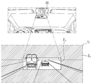
FIGS. 6 to 8 are views for explaining a lane departure warning function using the vehicle rear control system of FIG. 1. FIG.
The lane departure warning function can be activated when the lane departure warning function is in the D range.
That is, the
As a result, the
6, the
The
For example, as shown in FIG. 7, when the lane A on one side of the image I2 exceeds a predetermined threshold line B, the
The
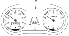
8 shows a case in which the lane departure warning is marked through the
The conventional lane departure warning function is mainly a method of acquiring an image of the front of the vehicle through a camera provided separately in front of the vehicle and recognizing the lane in the image of the vehicle ahead, The lane departure warning function according to this embodiment acquires an image of the rear of the vehicle using a rear camera, recognizes the lane in the acquired image of the rear of the vehicle, and detects the possibility of lane departure and lane departure on the basis of the detected lane.
The lane departure warning function according to the present embodiment may be operated only when the speed change stage is at the D-end and the vehicle speed is equal to or higher than a constant speed.
In this case, the
FIG. 9 is a diagram for explaining a MOD (Moving Object Detection) function using the vehicle rear control system of FIG. 1. FIG.
MOD (Moving Object Detection) is a function to detect a moving object from the rear of the vehicle through the rear image of the vehicle. It is a function to prevent an accident by detecting a pedestrian or an obstacle present in a blind spot in the rear of the vehicle and allowing the driver to recognize it.
The MOD function operates when the speed change stage is located at the R-stage.
That is, the
As a result, the
9, the
The
For example, the
The
When the moving subjects C1 to C3 are detected, as shown in FIG. 9, the frames surrounding the objects C1 to C3 are displayed on the
10 is a view for explaining a RVM (Rear View Monitoring) function using the vehicle rear control system of FIG.
The RVM (Rear View Monitoring) function is to display the rear image of the vehicle through a monitor inside the vehicle.
The RVM function can be operated with the speed change stage at the R-stage.
That is, the
As a result, the
10, the
After that, the
Therefore, the
When the MOD function described above is implemented at the same time, as shown in FIG. 10, image processing for the image I3 can be performed such that a box surrounding the moving subject is displayed through the
FIG. 11 is a view for explaining a motion-based trunk opening function using the vehicular rear control system of FIG. 1. FIG.
The motion-based trunk open function is a function to open a trunk by detecting a user's specific behavior, rather than opening the trunk using a conventional automobile key or a remote controller. As shown in FIG. 11, when the
The motion-based trunk release function can be operated with the speed change stage in the P-stage.
That is, the
As a result, the
The curvature of each of the
The
For example, if the preset motion is an operation in which the
If it is determined that the motion for trunk opening is normally performed through the analysis of the continuously shot images, the
In the case of a vehicle in which a smart key is used, the
FIG. 12 is a view for explaining a digital room mirror function using the vehicular rear control system of FIG. 1. FIG.
2 and 12, the digital room mirror is provided with a monitor (the second display portion 20) at the position of the existing room mirror, and the rear of the vehicle is photographed (Second display unit 20) to display an image obtained through the camera.
The digital room mirror function can always be operated when the vehicle is turned on regardless of the speed range.
In order to perform the digital room mirror function, the
Then, the
That is, the
Also, the room mirror is required to have a field of view of 20 meters left and right at a distance of 60 meters behind and 60 meters behind the room mirror. Further, it is required that a visual field of 22.4 degrees or more is secured in the left and right. Accordingly, the
As described above, the vehicular rear control system according to the embodiment of the present invention adjusts the wide angle by using the fluid lens, thereby making it possible to use a rearview camera for a vehicle to detect a lane departure warning function, a Moving Object Detection (MOD) View Monitoring, motion-based trunking, and digital room mirroring.
It will be understood by those skilled in the art that the present invention may be embodied in other specific forms without departing from the spirit or essential characteristics thereof. It is therefore to be understood that the above-described embodiments are illustrative in all aspects and not restrictive. The scope of the present invention is defined by the appended claims rather than the detailed description and all changes or modifications derived from the meaning and scope of the claims and their equivalents are to be construed as being included within the scope of the present invention do.
10: first display 20: second display
30: Cluster 40: Image processing unit
50: vehicle control section 60: trunk
70: rear camera 71: lens unit
71a: first
71c: third
73: lens control unit 100:
Claims (13)
An image sensor for capturing light passing through the fluid lens to generate image information;
A lens control unit for receiving the gear range information of the vehicle and controlling the curvature of the fluid lens according to the received gear range information to change the angle of view of the camera; And
And a display unit installed inside the vehicle and outputting the image information generated by the image sensor as an image.
The lens control unit controls the curvature of the fluid lens such that the angle of view is a first angle of view,
Wherein the lens control unit controls the curvature of the fluid lens so that the angle of view is a second angle of view larger than the first angle of view when the speed-change terminal information is R-stage or P-stage.
Wherein the first angle of view has an angular range of 110 degrees to 130 degrees.
Wherein the second angle of view has an angular range of greater than or equal to 160 degrees.
Further comprising an image processing unit for analyzing a rear image of the vehicle based on the image information generated by the image sensor,
When the gear range information corresponds to the D range,
Wherein the image processing unit detects a lane in the backward image and determines whether the vehicle is leaving the lane or departing from the lane.
Further comprising an image processing unit for analyzing a rear image of the vehicle based on the image information generated by the image sensor,
When the gear range information corresponds to the R-stage,
Wherein the image processing unit detects a moving subject in the rear image and expresses the moving subject on an image output to the display unit.
An image processor for analyzing a rear image of the vehicle based on the image information generated by the image sensor,
Further comprising a vehicle control section for controlling the trunk opening and closing of the vehicle,
When the speed change stage information corresponds to the P stage,
Wherein the image processing unit detects a preset motion in the backward image,
Wherein the vehicle control section opens the trunk when the image processing section detects a preset motion in the rear image.
An image processor for processing the image information generated by the image sensor;
Further comprising a second display unit installed in the vehicle and outputting the image information processed by the image processing unit as an image,
Wherein the image processing unit crops the rear image so that an image output to the second display unit has a third angle of view smaller than the second angle of view.
Wherein the third angle of view has an angular range of 22 degrees or greater.
The fluid lens comprising a first fluid lens and a second fluid lens positioned adjacent to the image sensor than the first fluid lens,
Wherein the camera further comprises at least one non-fluid lens provided between the first fluid lens and the second fluid lens.
The lens control unit includes:
Wherein the first fluid lens has a positive refracting power and the second fluid lens has a negative refracting power so as to control a curvature of the first fluid lens and the second fluid lens, Respectively,
Wherein the first fluid lens has a negative refracting power and the second fluid lens has a positive refracting power so as to control a curvature of the first fluid lens and the second fluid lens, To the vehicle rear control system.
Wherein the fluid lens includes a fluid for entering and exiting the fluid lens,
Wherein the lens control unit controls the curvature of the fluid lens by controlling an amount of the fluid entering and exiting.
The fluid lens includes a fluid whose shape is controlled by a current or a voltage,
Wherein the lens control unit controls a curvature of the fluid lens by applying a current or voltage to the fluid.
Priority Applications (1)
| Application Number | Priority Date | Filing Date | Title |
|---|---|---|---|
| KR1020150091801A KR20170001984A (en) | 2015-06-29 | 2015-06-29 | Rear view monitoring system for vehicle |
Applications Claiming Priority (1)
| Application Number | Priority Date | Filing Date | Title |
|---|---|---|---|
| KR1020150091801A KR20170001984A (en) | 2015-06-29 | 2015-06-29 | Rear view monitoring system for vehicle |
Publications (1)
| Publication Number | Publication Date |
|---|---|
| KR20170001984A true KR20170001984A (en) | 2017-01-06 |
Family
ID=57832271
Family Applications (1)
| Application Number | Title | Priority Date | Filing Date |
|---|---|---|---|
| KR1020150091801A KR20170001984A (en) | 2015-06-29 | 2015-06-29 | Rear view monitoring system for vehicle |
Country Status (1)
| Country | Link |
|---|---|
| KR (1) | KR20170001984A (en) |
Cited By (1)
| Publication number | Priority date | Publication date | Assignee | Title |
|---|---|---|---|---|
| KR20230038383A (en) | 2021-09-10 | 2023-03-20 | 임채환 | Map word development and implementation process 1 |
-
2015
- 2015-06-29 KR KR1020150091801A patent/KR20170001984A/en unknown
Cited By (1)
| Publication number | Priority date | Publication date | Assignee | Title |
|---|---|---|---|---|
| KR20230038383A (en) | 2021-09-10 | 2023-03-20 | 임채환 | Map word development and implementation process 1 |
Similar Documents
| Publication | Publication Date | Title |
|---|---|---|
| JP5099451B2 (en) | Vehicle periphery confirmation device | |
| KR101789984B1 (en) | Side Mirror Camera System For Vehicle | |
| US20080199069A1 (en) | Stereo Camera for a Motor Vehicle | |
| US11783600B2 (en) | Adaptive monitoring of a vehicle using a camera | |
| JP2005126068A (en) | Adaptively imaging night vision device | |
| JP2020024532A (en) | Inattentive driving detection device | |
| WO2020195770A1 (en) | State detecting device, state detecting system, and state detecting method | |
| CN113875217A (en) | Image recognition apparatus and image recognition method | |
| KR101986734B1 (en) | Driver assistance apparatus in vehicle and method for guidance a safety driving thereof | |
| JPH03254291A (en) | Monitor for automobile driver | |
| US9662979B2 (en) | Method for presenting safety information, driver assistance system and motor vehicle | |
| US20230174074A1 (en) | In-cabin safety sensor installed in vehicle and method of providing service platform thereof | |
| KR102494530B1 (en) | Camera Apparatus Installing at a Car for Detecting Drowsy Driving and Careless Driving and Method thereof | |
| KR20170001984A (en) | Rear view monitoring system for vehicle | |
| US11810372B2 (en) | Multiple in-cabin cameras and lighting sources for driver monitoring | |
| KR102457633B1 (en) | Apparatus for real-time road condition check of vehicle front on the right outdoor side | |
| KR102010407B1 (en) | Smart Rear-view System | |
| JP2018162030A (en) | Display device for vehicle | |
| US11778316B2 (en) | Imaging apparatus | |
| KR102197196B1 (en) | Apparatus for controlling focus of car back box and method thereof | |
| KR102588904B1 (en) | In-Cabin Security Sensor Installed at a Car | |
| JP7409544B1 (en) | Driving support device | |
| KR20170001985A (en) | Black box system for vehicle using variable liquid lens | |
| JP7185571B2 (en) | Viewing direction estimation device, viewing direction estimation method, and program | |
| KR200484997Y1 (en) | Vehicl side mirror using endoscope |