KR20160146720A - Inductive power supply for vehicles comprising a plurality of charging coils havuing a shorter pitch than the pick-up coils - Google Patents
Inductive power supply for vehicles comprising a plurality of charging coils havuing a shorter pitch than the pick-up coils Download PDFInfo
- Publication number
- KR20160146720A KR20160146720A KR1020167029327A KR20167029327A KR20160146720A KR 20160146720 A KR20160146720 A KR 20160146720A KR 1020167029327 A KR1020167029327 A KR 1020167029327A KR 20167029327 A KR20167029327 A KR 20167029327A KR 20160146720 A KR20160146720 A KR 20160146720A
- Authority
- KR
- South Korea
- Prior art keywords
- charging
- coils
- vehicle
- pads
- electric vehicle
- Prior art date
Links
Images


Classifications
-
- B60L11/182—
-
- B—PERFORMING OPERATIONS; TRANSPORTING
- B60—VEHICLES IN GENERAL
- B60L—PROPULSION OF ELECTRICALLY-PROPELLED VEHICLES; SUPPLYING ELECTRIC POWER FOR AUXILIARY EQUIPMENT OF ELECTRICALLY-PROPELLED VEHICLES; ELECTRODYNAMIC BRAKE SYSTEMS FOR VEHICLES IN GENERAL; MAGNETIC SUSPENSION OR LEVITATION FOR VEHICLES; MONITORING OPERATING VARIABLES OF ELECTRICALLY-PROPELLED VEHICLES; ELECTRIC SAFETY DEVICES FOR ELECTRICALLY-PROPELLED VEHICLES
- B60L53/00—Methods of charging batteries, specially adapted for electric vehicles; Charging stations or on-board charging equipment therefor; Exchange of energy storage elements in electric vehicles
- B60L53/10—Methods of charging batteries, specially adapted for electric vehicles; Charging stations or on-board charging equipment therefor; Exchange of energy storage elements in electric vehicles characterised by the energy transfer between the charging station and the vehicle
- B60L53/12—Inductive energy transfer
-
- B60L11/1829—
-
- B—PERFORMING OPERATIONS; TRANSPORTING
- B60—VEHICLES IN GENERAL
- B60L—PROPULSION OF ELECTRICALLY-PROPELLED VEHICLES; SUPPLYING ELECTRIC POWER FOR AUXILIARY EQUIPMENT OF ELECTRICALLY-PROPELLED VEHICLES; ELECTRODYNAMIC BRAKE SYSTEMS FOR VEHICLES IN GENERAL; MAGNETIC SUSPENSION OR LEVITATION FOR VEHICLES; MONITORING OPERATING VARIABLES OF ELECTRICALLY-PROPELLED VEHICLES; ELECTRIC SAFETY DEVICES FOR ELECTRICALLY-PROPELLED VEHICLES
- B60L5/00—Current collectors for power supply lines of electrically-propelled vehicles
- B60L5/005—Current collectors for power supply lines of electrically-propelled vehicles without mechanical contact between the collector and the power supply line
-
- B—PERFORMING OPERATIONS; TRANSPORTING
- B60—VEHICLES IN GENERAL
- B60L—PROPULSION OF ELECTRICALLY-PROPELLED VEHICLES; SUPPLYING ELECTRIC POWER FOR AUXILIARY EQUIPMENT OF ELECTRICALLY-PROPELLED VEHICLES; ELECTRODYNAMIC BRAKE SYSTEMS FOR VEHICLES IN GENERAL; MAGNETIC SUSPENSION OR LEVITATION FOR VEHICLES; MONITORING OPERATING VARIABLES OF ELECTRICALLY-PROPELLED VEHICLES; ELECTRIC SAFETY DEVICES FOR ELECTRICALLY-PROPELLED VEHICLES
- B60L53/00—Methods of charging batteries, specially adapted for electric vehicles; Charging stations or on-board charging equipment therefor; Exchange of energy storage elements in electric vehicles
- B60L53/10—Methods of charging batteries, specially adapted for electric vehicles; Charging stations or on-board charging equipment therefor; Exchange of energy storage elements in electric vehicles characterised by the energy transfer between the charging station and the vehicle
- B60L53/12—Inductive energy transfer
- B60L53/122—Circuits or methods for driving the primary coil, e.g. supplying electric power to the coil
-
- B—PERFORMING OPERATIONS; TRANSPORTING
- B60—VEHICLES IN GENERAL
- B60L—PROPULSION OF ELECTRICALLY-PROPELLED VEHICLES; SUPPLYING ELECTRIC POWER FOR AUXILIARY EQUIPMENT OF ELECTRICALLY-PROPELLED VEHICLES; ELECTRODYNAMIC BRAKE SYSTEMS FOR VEHICLES IN GENERAL; MAGNETIC SUSPENSION OR LEVITATION FOR VEHICLES; MONITORING OPERATING VARIABLES OF ELECTRICALLY-PROPELLED VEHICLES; ELECTRIC SAFETY DEVICES FOR ELECTRICALLY-PROPELLED VEHICLES
- B60L53/00—Methods of charging batteries, specially adapted for electric vehicles; Charging stations or on-board charging equipment therefor; Exchange of energy storage elements in electric vehicles
- B60L53/10—Methods of charging batteries, specially adapted for electric vehicles; Charging stations or on-board charging equipment therefor; Exchange of energy storage elements in electric vehicles characterised by the energy transfer between the charging station and the vehicle
- B60L53/12—Inductive energy transfer
- B60L53/126—Methods for pairing a vehicle and a charging station, e.g. establishing a one-to-one relation between a wireless power transmitter and a wireless power receiver
-
- B—PERFORMING OPERATIONS; TRANSPORTING
- B60—VEHICLES IN GENERAL
- B60L—PROPULSION OF ELECTRICALLY-PROPELLED VEHICLES; SUPPLYING ELECTRIC POWER FOR AUXILIARY EQUIPMENT OF ELECTRICALLY-PROPELLED VEHICLES; ELECTRODYNAMIC BRAKE SYSTEMS FOR VEHICLES IN GENERAL; MAGNETIC SUSPENSION OR LEVITATION FOR VEHICLES; MONITORING OPERATING VARIABLES OF ELECTRICALLY-PROPELLED VEHICLES; ELECTRIC SAFETY DEVICES FOR ELECTRICALLY-PROPELLED VEHICLES
- B60L53/00—Methods of charging batteries, specially adapted for electric vehicles; Charging stations or on-board charging equipment therefor; Exchange of energy storage elements in electric vehicles
- B60L53/30—Constructional details of charging stations
- B60L53/305—Communication interfaces
-
- B—PERFORMING OPERATIONS; TRANSPORTING
- B60—VEHICLES IN GENERAL
- B60L—PROPULSION OF ELECTRICALLY-PROPELLED VEHICLES; SUPPLYING ELECTRIC POWER FOR AUXILIARY EQUIPMENT OF ELECTRICALLY-PROPELLED VEHICLES; ELECTRODYNAMIC BRAKE SYSTEMS FOR VEHICLES IN GENERAL; MAGNETIC SUSPENSION OR LEVITATION FOR VEHICLES; MONITORING OPERATING VARIABLES OF ELECTRICALLY-PROPELLED VEHICLES; ELECTRIC SAFETY DEVICES FOR ELECTRICALLY-PROPELLED VEHICLES
- B60L53/00—Methods of charging batteries, specially adapted for electric vehicles; Charging stations or on-board charging equipment therefor; Exchange of energy storage elements in electric vehicles
- B60L53/30—Constructional details of charging stations
- B60L53/35—Means for automatic or assisted adjustment of the relative position of charging devices and vehicles
- B60L53/38—Means for automatic or assisted adjustment of the relative position of charging devices and vehicles specially adapted for charging by inductive energy transfer
-
- B—PERFORMING OPERATIONS; TRANSPORTING
- B60—VEHICLES IN GENERAL
- B60M—POWER SUPPLY LINES, AND DEVICES ALONG RAILS, FOR ELECTRICALLY- PROPELLED VEHICLES
- B60M7/00—Power lines or rails specially adapted for electrically-propelled vehicles of special types, e.g. suspension tramway, ropeway, underground railway
- B60M7/003—Power lines or rails specially adapted for electrically-propelled vehicles of special types, e.g. suspension tramway, ropeway, underground railway for vehicles using stored power (e.g. charging stations)
-
- H—ELECTRICITY
- H02—GENERATION; CONVERSION OR DISTRIBUTION OF ELECTRIC POWER
- H02J—CIRCUIT ARRANGEMENTS OR SYSTEMS FOR SUPPLYING OR DISTRIBUTING ELECTRIC POWER; SYSTEMS FOR STORING ELECTRIC ENERGY
- H02J50/00—Circuit arrangements or systems for wireless supply or distribution of electric power
- H02J50/10—Circuit arrangements or systems for wireless supply or distribution of electric power using inductive coupling
- H02J50/12—Circuit arrangements or systems for wireless supply or distribution of electric power using inductive coupling of the resonant type
-
- H—ELECTRICITY
- H02—GENERATION; CONVERSION OR DISTRIBUTION OF ELECTRIC POWER
- H02J—CIRCUIT ARRANGEMENTS OR SYSTEMS FOR SUPPLYING OR DISTRIBUTING ELECTRIC POWER; SYSTEMS FOR STORING ELECTRIC ENERGY
- H02J50/00—Circuit arrangements or systems for wireless supply or distribution of electric power
- H02J50/40—Circuit arrangements or systems for wireless supply or distribution of electric power using two or more transmitting or receiving devices
-
- B—PERFORMING OPERATIONS; TRANSPORTING
- B60—VEHICLES IN GENERAL
- B60Y—INDEXING SCHEME RELATING TO ASPECTS CROSS-CUTTING VEHICLE TECHNOLOGY
- B60Y2200/00—Type of vehicle
- B60Y2200/90—Vehicles comprising electric prime movers
- B60Y2200/91—Electric vehicles
-
- B—PERFORMING OPERATIONS; TRANSPORTING
- B60—VEHICLES IN GENERAL
- B60Y—INDEXING SCHEME RELATING TO ASPECTS CROSS-CUTTING VEHICLE TECHNOLOGY
- B60Y2200/00—Type of vehicle
- B60Y2200/90—Vehicles comprising electric prime movers
- B60Y2200/92—Hybrid vehicles
-
- Y—GENERAL TAGGING OF NEW TECHNOLOGICAL DEVELOPMENTS; GENERAL TAGGING OF CROSS-SECTIONAL TECHNOLOGIES SPANNING OVER SEVERAL SECTIONS OF THE IPC; TECHNICAL SUBJECTS COVERED BY FORMER USPC CROSS-REFERENCE ART COLLECTIONS [XRACs] AND DIGESTS
- Y02—TECHNOLOGIES OR APPLICATIONS FOR MITIGATION OR ADAPTATION AGAINST CLIMATE CHANGE
- Y02T—CLIMATE CHANGE MITIGATION TECHNOLOGIES RELATED TO TRANSPORTATION
- Y02T10/00—Road transport of goods or passengers
- Y02T10/60—Other road transportation technologies with climate change mitigation effect
- Y02T10/70—Energy storage systems for electromobility, e.g. batteries
-
- Y—GENERAL TAGGING OF NEW TECHNOLOGICAL DEVELOPMENTS; GENERAL TAGGING OF CROSS-SECTIONAL TECHNOLOGIES SPANNING OVER SEVERAL SECTIONS OF THE IPC; TECHNICAL SUBJECTS COVERED BY FORMER USPC CROSS-REFERENCE ART COLLECTIONS [XRACs] AND DIGESTS
- Y02—TECHNOLOGIES OR APPLICATIONS FOR MITIGATION OR ADAPTATION AGAINST CLIMATE CHANGE
- Y02T—CLIMATE CHANGE MITIGATION TECHNOLOGIES RELATED TO TRANSPORTATION
- Y02T10/00—Road transport of goods or passengers
- Y02T10/60—Other road transportation technologies with climate change mitigation effect
- Y02T10/7072—Electromobility specific charging systems or methods for batteries, ultracapacitors, supercapacitors or double-layer capacitors
-
- Y—GENERAL TAGGING OF NEW TECHNOLOGICAL DEVELOPMENTS; GENERAL TAGGING OF CROSS-SECTIONAL TECHNOLOGIES SPANNING OVER SEVERAL SECTIONS OF THE IPC; TECHNICAL SUBJECTS COVERED BY FORMER USPC CROSS-REFERENCE ART COLLECTIONS [XRACs] AND DIGESTS
- Y02—TECHNOLOGIES OR APPLICATIONS FOR MITIGATION OR ADAPTATION AGAINST CLIMATE CHANGE
- Y02T—CLIMATE CHANGE MITIGATION TECHNOLOGIES RELATED TO TRANSPORTATION
- Y02T90/00—Enabling technologies or technologies with a potential or indirect contribution to GHG emissions mitigation
- Y02T90/10—Technologies relating to charging of electric vehicles
- Y02T90/12—Electric charging stations
-
- Y—GENERAL TAGGING OF NEW TECHNOLOGICAL DEVELOPMENTS; GENERAL TAGGING OF CROSS-SECTIONAL TECHNOLOGIES SPANNING OVER SEVERAL SECTIONS OF THE IPC; TECHNICAL SUBJECTS COVERED BY FORMER USPC CROSS-REFERENCE ART COLLECTIONS [XRACs] AND DIGESTS
- Y02—TECHNOLOGIES OR APPLICATIONS FOR MITIGATION OR ADAPTATION AGAINST CLIMATE CHANGE
- Y02T—CLIMATE CHANGE MITIGATION TECHNOLOGIES RELATED TO TRANSPORTATION
- Y02T90/00—Enabling technologies or technologies with a potential or indirect contribution to GHG emissions mitigation
- Y02T90/10—Technologies relating to charging of electric vehicles
- Y02T90/14—Plug-in electric vehicles
-
- Y—GENERAL TAGGING OF NEW TECHNOLOGICAL DEVELOPMENTS; GENERAL TAGGING OF CROSS-SECTIONAL TECHNOLOGIES SPANNING OVER SEVERAL SECTIONS OF THE IPC; TECHNICAL SUBJECTS COVERED BY FORMER USPC CROSS-REFERENCE ART COLLECTIONS [XRACs] AND DIGESTS
- Y02—TECHNOLOGIES OR APPLICATIONS FOR MITIGATION OR ADAPTATION AGAINST CLIMATE CHANGE
- Y02T—CLIMATE CHANGE MITIGATION TECHNOLOGIES RELATED TO TRANSPORTATION
- Y02T90/00—Enabling technologies or technologies with a potential or indirect contribution to GHG emissions mitigation
- Y02T90/10—Technologies relating to charging of electric vehicles
- Y02T90/16—Information or communication technologies improving the operation of electric vehicles
Landscapes
- Engineering & Computer Science (AREA)
- Power Engineering (AREA)
- Mechanical Engineering (AREA)
- Transportation (AREA)
- Computer Networks & Wireless Communication (AREA)
- Charge And Discharge Circuits For Batteries Or The Like (AREA)
- Electric Propulsion And Braking For Vehicles (AREA)
- Current-Collector Devices For Electrically Propelled Vehicles (AREA)
Abstract
동적 무선 충전 시스템들은 동적 무선 충전 시스템이 설치되어 있는 거리를 따라서 움직이는 수신기에 조정되는 계속적인 전력 전송들을 제공하기 위해 다수의 베이스 패드들을 조정하는 것을 수반할 수도 있다. 이러한 동적 시스템들은 베이스 어레이 네트워크들 (BAN 모듈들) 에서의 컴포넌트들일 수도 있는 많은 개수의 코일들 (베이스 패드들) 을 요구할 수도 있다. BAN 모듈들은 간소화된 설치 및 시스템 설계를 제공할 수도 있으며, 여기서 BAN 모듈들은 사전어셈블리되고, 자체-포함된, 드롭-인-플레이스 (drop-in-place) 유닛들일 수도 있다. BAN 모듈들의 레이아웃 및 설계는 충전 베이스 패드들, 로컬 제어기들, 분배 회로부, 및 스위칭 제어부들을 포함할 수도 있다. BAN 모듈들의 사이즈 정하기는 그러한 동적 시스템들의 이용가능성 및 실용성에 급격히 영향을 줄 수도 있다. BAN 모듈들의 사이즈 정하기는 전기 차량들 상의 차량 패드들 사이의 피치 및 BAN 모듈들 내의 베이스 패드 피치에 의존할 수도 있다.Dynamic wireless charging systems may involve coordinating a number of base pads to provide continuous power transmissions that are tuned to a receiver moving along a distance that a dynamic wireless charging system is installed. These dynamic systems may require a large number of coils (base pads), which may be components in the base array networks (BAN modules). The BAN modules may provide a simplified installation and system design, where the BAN modules may be pre-assembled, self-contained, drop-in-place units. The layout and design of the BAN modules may include charge base pads, local controllers, distribution circuitry, and switching controls. Determining the size of BAN modules may have a dramatic impact on the availability and practicality of such dynamic systems. The sizing of the BAN modules may depend on the pitch between the vehicle pads on the electric vehicles and the base pad pitch in the BAN modules.

Description
본 출원은 일반적으로 전기 차량들과 같은 충전가능한 디바이스들의 무선 전력 충전에 관한 것이다.The present application relates generally to wireless power charging of rechargeable devices such as electric vehicles.
배터리와 같은 에너지 저장 디바이스로부터 수신된 전기로부터 도출된 운동 전력 (locomotion power) 을 포함하는 충전가능한 시스템들, 예컨대, 차량들이 도입되었다. 예를 들어, 하이브리드 전기 차량들은 차량들을 충전하기 위해 차량 브레이킹 및 통상의 모터들로부터 전력을 이용하는 온-보드 충전기들을 포함한다. 전기 전용 차량들은 일반적으로 다른 소스들로부터 배터리들을 충전하기 위한 전기를 수신한다. 배터리 전기 차량들은 종종, 일부 유형의 유선 교류 전류 (alternating current; AC), 예컨대, 가정용 또는 상업용 AC 공급 소스들을 통하여 충전되도록 제안된다. 유선 충전 접속들은 전력 공급기에 물리적으로 접속되는 케이블들 또는 다른 유사한 커넥터들을 요구한다. 케이블들 및 유사한 커넥터들은 때때로 불편하거나 다루기 힘들고 다른 단점들을 갖는다. 전기 차량들을 충전하는데 이용될 자유 공간에서 (예컨대, 무선 필드를 통해) 전력을 전송할 수 있는 무선 충전 시스템들이 유선 충전 솔루션들의 일부 결함들을 극복할 수도 있다. 추가적으로, 무선 충전 시스템은 실질적인 방식으로 확장된 이동 거리에 걸쳐 움직이는 수신기에 계속해서 전력을 전송을 적절히 조정하도록 다수의 베이스 패드들을 조정할 수 있어야 한다.BACKGROUND OF THE INVENTION [0002] Rechargeable systems, e.g., vehicles, have been introduced that include locomotion power derived from electricity received from an energy storage device such as a battery. For example, hybrid electric vehicles include vehicle braking to charge vehicles and on-board chargers that utilize power from conventional motors. Electric-only vehicles typically receive electricity to charge batteries from other sources. Battery powered vehicles are often suggested to be charged through some type of alternating current (AC), for example, household or commercial AC supply sources. Wired charging connections require cables or other similar connectors that are physically connected to the power supply. Cables and similar connectors are sometimes inconvenient, unwieldy, and have other disadvantages. Wireless charging systems capable of transferring power in a free space (e.g., via a wireless field) that will be used to charge electric vehicles may overcome some of the deficiencies of wired charging solutions. In addition, the wireless charging system must be able to adjust a number of base pads to properly adjust power transfer to the receiver moving over the extended travel distance in a substantial manner.
본원에 개시된 실시예들은 여러 혁신적인 양태들을 각각 가지며, 이들 중 어느 하나도 본 발명의 바람직한 속성들을 단독으로 책임지지 않는다. 범위를 제한하지 않으면서, 뒤따르는 청구항들에 의해 설명된 바와 같이, 보다 중요한 피쳐들이 본원에 간략하게 개시될 것이다. 이러한 논의를 고려한 후에, 다양한 실시예들의 피쳐들이 현재의 동적 무선 충전 시스템들에 비해 여러 이점들을 어떻게 제공하는지를 이해할 것이다.The embodiments disclosed herein each have several innovative aspects, none of which is solely responsible for the desired attributes of the present invention. Without limiting the scope, more important features will be briefly described herein, as described by the claims that follow. After considering this discussion, it will be appreciated how the features of the various embodiments provide several advantages over current dynamic wireless charging systems.
본 발명의 일 실시예는 전기 차량을 충전하기 위한 디바이스를 포함하며, 그 디바이스는 전기 차량을 충전하도록 구성된 복수의 충전 코일들로서, 복수의 충전 코일들 중 임의의 2 개의 충전 코일들 사이의 길이는 전기 차량의 적어도 2 개의 차량 패드들 사이의 피치보다 작은, 상기 복수의 충전 코일들, 충전 코일들 중 하나에 전력을 선택적으로 분배하도록 구성된 복수의 제어 유닛들, 및 충전 코일들 중 하나를 제어 유닛들 중 하나에 선택적으로 커플링하도록 구성된 복수의 충전 코일 스위치들을 포함한다.One embodiment of the invention includes a device for charging an electric vehicle, the device comprising a plurality of charging coils configured to charge an electric vehicle, the length between any two charging coils of the plurality of charging coils is A plurality of charging coils, a plurality of control units configured to selectively distribute power to one of the charging coils, and one of the charging coils, which is smaller than a pitch between at least two vehicle pads of the electric vehicle, And a plurality of charging coil switches configured to selectively couple to one of the plurality of charging coil switches.
본 발명의 다른 실시예는 어레이를 발생시키기 위한 방법을 포함할 수도 있으며, 그 방법은 전기 차량을 충전하도록 구성된 복수의 충전 코일들을 제공하는 단계로서, 복수의 충전 코일들 중 임의의 2 개의 충전 코일들 사이의 길이는 전기 차량의 적어도 2 개의 차량 패드들 사이의 피치보다 작은, 상기 복수의 충전 코일들을 제공하는 단계, 충전 코일들 중 하나에 전력을 선택적으로 분배하도록 구성된 복수의 제어 유닛들을 제공하는 단계, 및 충전 코일들 중 하나를 제어 유닛들 중 하나에 선택적으로 커플링하도록 구성된 복수의 충전 코일 스위치들을 제공하는 단계를 포함한다.Another embodiment of the present invention may include a method for generating an array, the method comprising: providing a plurality of charging coils configured to charge an electric vehicle, Providing a plurality of charging coils, the length of which is less than a pitch between at least two vehicle pads of an electric vehicle, a plurality of control units configured to selectively distribute power to one of the charging coils And providing a plurality of charge coil switches configured to selectively couple one of the charge coils to one of the control units.
추가적인 실시예들은 전기 차량을 충전하기 위한 디바이스를 포함할 수도 있으며, 그 디바이스는 전기 차량을 무선으로 충전하기 위한 복수의 수단으로서, 복수의 무선으로 충전하는 수단 중 임의의 2 개의 무선으로 충전하는 수단 사이의 길이는 전기 차량의 적어도 2 개의 차량 패드들 사이의 피치보다 작은, 상기 전기 차량을 무선으로 충전하기 위한 복수의 수단, 무선으로 충전하는 수단 중 하나에 전력을 선택적으로 분배하기 위한 복수의 수단, 및 무선으로 충전하는 수단 중 하나를 분배하는 수단 중 하나에 선택적으로 커플링하기 위한 복수의 수단을 포함한다.Additional embodiments may include a device for charging an electric vehicle, the device comprising a plurality of means for wirelessly charging an electric vehicle, the device comprising means for charging any two of the plurality of wireless charging means A plurality of means for charging the electric vehicle wirelessly, a plurality of means for selectively distributing electric power to one of the means for charging wirelessly, a length between the plurality of means being less than the pitch between the at least two vehicle pads of the electric vehicle, And means for distributing one of the means for charging wirelessly.
본 기술의 위에서 언급된 양태들, 뿐만 아니라 다른 피쳐들, 양태들, 및 이점들은 이제 첨부 도면들을 참조하여 다양한 실시예들과 연계하여 설명될 것이다. 예시된 실시예들은, 그러나, 단지 예들일 뿐이고 제한하는 것으로 의도되지는 않는다. 도면들에 걸쳐서, 문맥상 다르게 지시하지 않는 한, 유사한 도면 부호들은 통상 유사한 컴포넌트를 식별한다. 첨부된 도면에서 상대적인 치수들은 일정한 축척으로 그려지지 않을 수도 있음에 유의한다.
도 1 은 일 구현예의 일 예에 따른, 예시적인 무선 전력 전송 시스템의 기능 블록도이다.
도 2 는 일 구현예의 다른 예에 따른, 예시적인 무선 전력 전송 시스템의 기능 블록도이다.
도 3 은 예시적인 구현예들에 따른, 송신 또는 수신 안테나를 포함하는 도 2 의 송신 회로부 또는 수신 회로부의 일부분의 개략도이다.
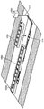
도 4 는 도로를 따라 이동하는 적어도 하나의 차량 패드를 갖는 전기 차량의 개략도를 도시하며, 여기서 동적 무선 충전 시스템의 다양한 컴포넌트들은 도로 아래에 설치된다.
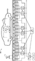
도 5a 는 도 4 에 도시된 베이스 어레이 네트워크 (base array network; BAN) 모듈의 개략도를 도시한다.
도 5b 는 일 예의 모듈러 인클로져 내에 포함되어 있는 도 4 에 도시된 베이스 어레이 네트워크 (BAN) 모듈의 일 실시예를 도시한다.
도 6 은 도관 및 인클로져에 접속되면서, 도로에서의, 도 5 로부터의 다수의 BAN 모듈들의 설치의 일 예를 도시한다.
도 7 은 도 4 의 개략도를 도시하며, 여기서 전기 차량은 차량 패드 피치를 갖는 2 개의 차량 패드들을 포함하고, 베이스 패드 피치가 또한 도시된다.
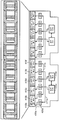
도 8 은 도 4 내지 도 7 의 BAN 모듈들의 실시예들의 2 개의 연속하는 예들의 개략도 및 투시도를 대응하는 도시한다.
도 9 는 예시적인 베이스 패드 활성화 시퀀스의 다양한 베이스 패드 활성화 시퀀스 단계들의 투시도를 도시한다.
도 10 은 베이스 패드들 위로 이동하는 차량 패드들과 함께 도로에 따른 베이스 패드들의 중첩하는 레이아웃의 일 예의 투시도를 도시한다.
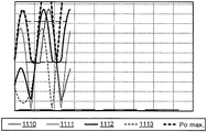
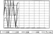
도 11a 는 베이스 패드 피치 및 차량 패드 피치를 갖는 베이스 패드들 위의 차량 패드 포지션들에 대한 베이스 패드들 및 차량 패드들의 각각 사이의 결합된 커플링의 일 예의 그래프를 도시한다.
도 11b 는 다른 베이스 패드 피치 및 차량 패드 피치를 갖는 베이스 패드들 위의 차량 패드 포지션들에 대한 베이스 패드들 및 차량 패드들의 각각 사이의 결합된 커플링의 다른 예의 그래프를 도시한다.
도 11c 는 일 예시적인 베이스 패드 피치 및 차량 패드 피치를 갖는 베이스 패드들 위의 차량 패드 포지션들에 대한 베이스 패드들 및 차량 패드들의 각각을 통한 전기 차량에 대한 결합된 전력 전송의 제 3 예의 그래프를 도시한다.
도 12 는 도 4 내지 도 8 의 베이스 어레이 네트워크 (BAN) 모듈의 제조의 방법을 도시한다.The above-mentioned aspects, as well as other features, aspects, and advantages of the present technology will now be described in connection with various embodiments with reference to the accompanying drawings. The illustrated embodiments are, however, by way of example only and are not intended to be limiting. Throughout the Figures, like reference numerals usually identify similar components, unless the context clearly indicates otherwise. It should be noted that the relative dimensions in the attached drawings may not be drawn to a certain scale.
1 is a functional block diagram of an exemplary wireless power transmission system, in accordance with an example of one implementation.
2 is a functional block diagram of an exemplary wireless power transmission system, in accordance with another example of an implementation.
3 is a schematic diagram of a portion of the transmitting or receiving circuitry of FIG. 2, including a transmitting or receiving antenna, in accordance with exemplary implementations.
4 shows a schematic view of an electric vehicle having at least one vehicle pad moving along the road, wherein various components of the dynamic wireless charging system are installed under the road.
FIG. 5A shows a schematic diagram of the base array network (BAN) module shown in FIG.
FIG. 5B illustrates an embodiment of the base array network (BAN) module shown in FIG. 4 included within an exemplary modular enclosure.
Fig. 6 shows an example of the installation of a number of BAN modules from Fig. 5, on the road, connected to a conduit and an enclosure.
FIG. 7 shows a schematic view of FIG. 4, wherein the electric vehicle includes two vehicle pads having a vehicle pad pitch, and a base pad pitch is also shown.
Figure 8 shows a schematic and perspective view of two successive examples of embodiments of BAN modules of Figures 4-7 correspondingly.
Figure 9 shows a perspective view of various base pad activation sequence steps of an exemplary base pad activation sequence.
Figure 10 shows a perspective view of an example of the overlapping layout of base pads along the road with vehicle pads moving over the base pads.
11A shows a graph of an example of coupled coupling between base pads and each of the vehicle pads with respect to vehicle pad positions on base pads having base pad pitch and vehicle pad pitch.
11B shows a graph of another example of coupled coupling between base pads and each of the vehicle pads for vehicle pad positions on base pads having different base pad pitches and vehicle pad pitches.
11C is a graph of a third example of combined power transmission for an electric vehicle through base pads and vehicle pads for vehicle pad positions on base pads having an exemplary base pad pitch and vehicle pad pitch, Respectively.
Figure 12 illustrates a method of manufacturing the base array network (BAN) module of Figures 4-8.
다음의 상세한 설명에서는, 본 개시물의 일부분을 형성하는 첨부 도면들에 대한 참조가 이루어진다. 상세한 설명, 도면, 및 청구항들에서 설명된 예시적인 실시예들은 제한적인 것을 의미하는 것은 아니다. 본원에서 제시된 대상의 취지 또는 범위를 벗어나지 않으면서, 다른 실시예들이 활용될 수도 있고, 다른 변경예들이 이루어질 수도 있다. 본원에서 일반적으로 설명되고, 도면들에서 도시된 본 개시물의 양태들은 아주 다양하고 상이한 구성들로 배열되고, 대체되고, 조합되고, 설계될 수 있으며, 이들 모두가 본원에서 명시적으로 고려되고 본 개시물의 일부분을 형성한다는 것이 쉽게 이해될 것이다.In the following detailed description, reference is made to the accompanying drawings which form a part hereof. The illustrative embodiments set forth in the description, drawings, and claims are not meant to be limiting. Other embodiments may be utilized and other variations may be made without departing from the spirit or scope of the subject matter presented herein. Aspects of the disclosure that are generally described herein and illustrated in the figures may be arranged, substituted, combined, and designed in a wide variety of different configurations, all of which are expressly contemplated herein and described in this disclosure It will be readily understood that it forms part of the water.
무선 전력 전송은 전기 필드들, 자기 필드들, 전자기 필드들과 연관되거나, 또는 그렇지 않으면 물리적 전기 전도체들의 이용없이 송신기로부터 수신기로 임의의 형태의 에너지를 전송하는 것을 지칭할 수도 있다 (예를 들어, 전력은 자유 공간을 통해서 전송될 수도 있다). 무선 필드 (예를 들어, 자기 필드 또는 전자기 필드) 로 출력된 전력은 전력 전송을 달성하기 위해 "수신 안테나" 에 의해 수신, 캡쳐, 또는 커플링될 수도 있다.Wireless power transmission may refer to transferring any form of energy from a transmitter to a receiver without being associated with electrical fields, magnetic fields, electromagnetic fields, or otherwise using physical electrical conductors (e.g., The power may be transmitted through free space). Power output to a wireless field (e.g., a magnetic field or an electromagnetic field) may be received, captured, or coupled by a "receiving antenna" to achieve power transmission.
전기 차량이 원격 시스템을 설명하기 위해 본원에서 이용되는데, 그 일례는, 그 모션 능력들의 일부로서, 충전가능한 에너지 저장 디바이스 (예를 들어, 하나 이상의 재충전가능 전기화학적 셀들 또는 다른 타입의 배터리) 로부터 도출되는 전기 전력을 포함하는 차량이다. 비제한적인 예들로서, 일부 전기 차량들은 전기 모터들 외에도, 직접적인 운동을 위한 또는 차량의 배터리를 충전하기 위한 종래의 연소 엔진을 포함하는 하이브리드 전기 차량들일 수도 있다. 다른 전기 차량들은 전기 차량으로부터의 모든 운동 능력을 인출할 수도 있다. 전기 차량은 자동차로 제한되지 않고 모터사이클들, 카트들, 스쿠터들 등을 포함할 수도 있다. 비제한적인 예로서, 원격 시스템은 본원에서 전기 차량 (electric vehicle; EV) 의 형태로 설명된다. 더욱이, 충전가능한 에너지 저장 디바이스를 이용하여 적어도 부분적으로 전력공급될 수도 있는 다른 원격 시스템들 (예컨대, 개인 컴퓨팅 디바이스들 등과 같은 전자 디바이스들) 이 또한 고려된다.An electric vehicle is used herein to describe a remote system, an example of which is derived from a rechargeable energy storage device (e.g., one or more rechargeable electrochemical cells or other types of batteries) as part of its motion capabilities Lt; RTI ID = 0.0 > electric < / RTI > By way of non-limiting example, some electric vehicles may be hybrid electric vehicles, including electric motors, as well as conventional combustion engines for direct motion or for charging the vehicle's battery. Other electric vehicles may withdraw all the athletic capabilities from the electric vehicle. Electric vehicles are not limited to automobiles and may include motor cycles, carts, scooters, and the like. By way of non-limiting example, the remote system is described herein in the form of an electric vehicle (EV). Moreover, other remote systems (e.g., electronic devices such as personal computing devices) that may be at least partially powered using a rechargeable energy storage device are also contemplated.
본원에서 이용된 전문용어는 단지 특정 실시예들을 설명하려는 목적이고, 본 개시물을 제한하려는 의도는 아니다. 청구항 엘리먼트의 특정 수가 의도되면, 그러한 의도는 청구항에서 명시적으로 인용될 것이며, 이러한 인용이 없으면 그러한 의도가 없는 것으로 당업자는 이해할 수 있을 것이다. 본원에서 사용된 바와 같이, 단수 형태들 "하나 (a)", "한 (an)" 및 "그 (the)" 는, 문맥상 그렇지 않다고 명확하게 나타내지 않는 한, 복수의 형태들도 포함하는 것으로 의도된다. 본원에서 이용된 바와 같이, 용어 "및/또는" 은 관련 열거된 아이템들의 하나 이상의 임의 및 모든 조합을 포함한다. 용어들 "포함하다", "포함하는", "포함시키다", 및/또는 "포함시키는" 은, 본원에서 이용되는 경우에는, 언급된 특색들, 인티저 (integer) 들, 단계들, 동작들, 요소들, 및/또는 컴포넌트들의 존재를 명시하나, 하나 이상의 다른 특색들, 인티저들, 단계들, 동작들, 요소들, 컴포넌트들, 및/또는 이들의 그룹들의 존재 또는 추가를 배제하지는 않음이 더 이해될 것이다. 엘리먼트들의 리스트가 선행하는 경우 "중 적어도 하나" 와 같은 표현은 엘리먼트들의 전체 리스트를 수정하고 리스트의 개개의 엘리먼트들을 수정하지는 않는다.The terminology used herein is for the purpose of describing particular embodiments only and is not intended to limit the disclosure. If a particular number of the claim element is intended, such intention will be explicitly recited in the claims, and those skilled in the art will understand that such a quotation is not intended to be so. As used herein, the singular forms "a," "an," and "the" include plural forms unless the context clearly dictates otherwise It is intended. As used herein, the term "and / or" includes any and all combinations of one or more of the listed listed items. The terms "comprise," "include," "include," and / or "including", when used herein, Elements, and / or components, but does not preclude the presence or addition of one or more other features, integers, steps, operations, elements, components, and / It will be understood more. Where a list of elements precedes, a representation such as "at least one of" modifies the entire list of elements and does not modify individual elements of the list.
도 1 은 일 예시적인 구현예에 따른, 예시적인 무선 전력 전송 시스템 (100) 의 기능 블록도이다. 에너지 전송을 수행하기 위한 무선 (예를 들어, 자기 또는 전자기) 필드 (105) 를 발생시키기 위해 전력 소스 (이 도면에서 미도시) 로부터 입력 전력 (102) 이 송신기 (104) 에 제공될 수도 있다. 수신기 (108) 는 무선 필드 (105) 에 커플링되어, 출력 전력 (110) 에 커플링된 디바이스 (이 도면에서 미도시) 에 의한 저장 또는 소비하기 위한 출력 전력 (110) 을 발생시킬 수도 있다. 송신기 (104) 및 수신기 (108) 양자 모두는 거리 (112) 만큼 분리된다.1 is a functional block diagram of an exemplary wireless
구현예의 일 예에서, 송신기 (104) 및 수신기 (108) 는 상호 공진 관계에 따라 구성된다. 수신기 (108) 의 공진 주파수와 송신기 (104) 의 공진 주파수가 실질적으로 동일하거나 매우 근접할 경우, 송신기 (104) 와 수신기 (108) 사이의 송신 손실들은 아주 적다. 이와 같이, 무선 전력 전송은, 코일들이 매우 근접할 것 (예를 들어, 수 밀리미터) 을 요구하는 큰 안테나 코일들을 요구할 수도 있는 순수하게 유도성인 솔루션들과 대조적으로 더 큰 거리에 걸쳐 제공될 수도 있다. 따라서, 공진 유도 커플링 기술들은 다양한 거리들에 걸쳐 그리고 다양한 유도 코일 구성들로 향상된 효율성 및 전력 전송을 가능하게 할 수도 있다.In one example of implementation, the
수신기 (108) 는, 수신기 (108) 가 송신기 (104) 에 의해 생성된 무선 에너지 필드 (105) 에 위치되는 경우 전력을 수신할 수도 있다. 무선 필드 (105) 는, 송신기 (104) 에 의해 출력된 에너지가 수신기 (108) 에 의해 캡쳐될 수도 있는 영역에 대응한다. 무선 필드 (105) 는 하기에서 더 설명될 바와 같은 송신기 (104) 의 "근접-필드" 에 대응할 수도 있다. 송신기 (104) 는 수신기 (108) 에 에너지를 송신하기 위한 송신 안테나 또는 코일 (114) 을 포함할 수도 있다. 수신기 (108) 는 송신기 (104) 로부터 송신된 에너지를 수신하거나 캡쳐하기 위한 수신 안테나 또는 코일 (118) 을 포함할 수도 있다. 근접-필드는 전력을 송신 코일 (114) 로부터 멀리 아주 적게 방사하는 송신 코일 (114) 내 전류들 및 전하들로부터 초래되는 강한 반응 필드들이 존재하는 영역에 대응할 수도 있다. 근접-필드는 송신 코일 (114) 의 약 일 파장 (또는 그것의 일부) 내에 있는 영역에 대응할 수도 있다.The
위에서 설명된 바와 같이, 전자기파에서의 에너지 대부분을 원거리 필드로 전파하는 것보다는 무선 필드 (105) 에서의 에너지의 많은 부분을 수신 코일 (118) 에 커플링시킴으로써, 효율적인 에너지 전송이 일어날 수도 있다. 무선 필드 (105) 내에 포지셔닝된 경우, "커플링 모드" 가 송신 코일 (114) 과 수신 코일 (118) 사이에서 전개될 수도 있다. 이러한 커플링이 일어날 수도 있는 송신 안테나 (114) 및 수신 안테나 (118) 주위의 구역은 본원에서 커플링-모드 영역이라고 지칭된다.As described above, efficient energy transfer may occur by coupling a large portion of the energy in the
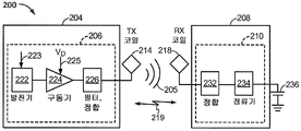
도 2 는 일 구현예의 다른 예에 따른, 예시적인 무선 전력 전송 시스템 (200) 의 기능 블록도이다. 시스템 (200) 은 도 1 의 시스템 (100) 과 유사한 동작 및 기능성의 무선 전력 전송 시스템일 수도 있다. 그러나, 시스템 (200) 은 도 1 외에 무선 전력 전송 시스템 (200) 의 컴포넌트들에 관한 추가적인 세부사항들을 제공한다. 도 1 의 시스템 (100) 은 도 2 에 도시된 것과 동일한 컴포넌트들 중 많은 컴포넌트들을 포함할 수도 있다. 시스템 (200) 은 송신기 (204) 및 수신기 (208) 를 포함한다. 송신기 (204) 는 발진기 (222), 구동 회로 (224), 그리고 필터 및 정합 회로 (226) 를 포함할 수도 있는 송신 회로부 (206) 를 포함할 수도 있다. 발진기 (222) 는 주파수 제어 신호 (223) 에 응답하여 조절될 수도 있는 원하는 주파수에서 신호를 발생시키도록 구성될 수도 있다. 발진기 (222) 는 구동 회로 (224) 에 발진기 신호를 제공할 수도 있다. 구동 회로 (224) 는, 예를 들어, 입력 전압 신호 (VD) (225) 에 기초하여 송신 안테나 (214) 의 공진 주파수에서 송신 안테나 (214) 를 구동하도록 구성될 수도 있다. 구동 회로 (224) 는 발진기 (222) 로부터 구형파를 수신하고 사인파를 출력하도록 구성된 스위칭 증폭기일 수도 있다. 예를 들어, 구동 회로 (224) 는 클래스 E 증폭기일 수도 있다. 2 is a functional block diagram of an exemplary wireless
필터 및 정합 회로 (226) 는 고조파 (harmonics) 또는 다른 원치 않는 주파수들을 필터링하고 송신기 (204) 의 임피던스를 송신 안테나 (214) 에 정합시킬 수도 있다. 송신 안테나 (214) 를 구동시킨 결과, 송신 안테나 (214) 는, 예를 들어, 전기 차량 (605) 의 배터리 (236) 를 충전하기에 충분한 레벨에서 전력을 무선으로 출력하기 위해 무선 필드 (205) 를 발생시킬 수도 있다.The filter and matching
수신기 (208) 는 정합 회로 (232) 및 정류 회로 (234) 를 포함할 수도 있는 수신 회로부 (210) 를 포함할 수도 있다. 정합 회로 (232) 는 수신 회로부 (210) 의 임피던스를 수신 안테나 (218) 에 정합시킬 수도 있다. 정류 회로 (234) 는 도 2 에 도시된 바와 같이 배터리 (236) 를 충전하기 위해 교류 (AC) 전력 입력으로부터 직류 (direct current; DC) 전력 출력을 발생시킬 수도 있다. 수신기 (208) 및 송신기 (204) 는 추가적으로, 별도의 통신 채널 (219) (예를 들어, 블루투스, 지그비, 셀룰러 등) 상으로 통신할 수도 있다. 수신기 (208) 및 송신기 (204) 는 대안적으로, 무선 필드 (205) 의 특성을 이용하여 대역-내 시그널링을 통신할 수도 있다.The
수신기 (208) 는 송신기 (204) 에 의해 송신되고 수신기 (208) 에 의해 수신된 전력의 양이 배터리 (236) 를 충전하기에 적절한지 여부를 결정하도록 구성될 수도 있다.The
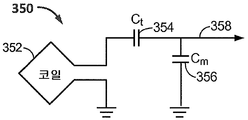
도 3 은 예시적인 구현예들에 따른, 도 2 의 송신 회로부 (206) 또는 수신 회로부 (210) 의 일부분의 개략도이다. 도 3 에 도시된 바와 같이, 송신 또는 수신 회로부 (350) 는 안테나 (352) 를 포함할 수도 있다. 안테나 (352) 는 또한 "루프" 안테나 (352) 로 지칭되거나 루프 안테나로서 구성될 수도 있다. 안테나 (352) 는 또한 "자기" 안테나 또는 유도 코일로 본원에서 지칭되거나 자기 안테나 또는 유도 코일로서 구성될 수도 있다. 용어 "안테나" 는 일반적으로 다른 "안테나" 에 커플링하기 위한 에너지를 무선으로 출력하거나 수신할 수도 있는 컴포넌트를 지칭한다. 안테나는 또한 전력을 무선으로 출력하거나 수신하도록 구성되는 타입의 "코일" 로서 지칭될 수도 있다. 본원에서 이용된 바와 같이, 안테나 (352) 는 전력을 무선으로 출력 및/또는 수신하도록 구성되는 일 타입의 "전력 전송 컴포넌트" 의 예이다.FIG. 3 is a schematic diagram of a portion of the transmit
안테나 (352) 는 공심 또는 페라이트와 같은 물리적 코어 (이 도면에는 미도시) 를 포함할 수도 있다. 공심 루프 안테나들은 코어의 근처에 놓인 외부의 물리적 디바이스들에 더 관대할 수도 있다. 또한, 공심 루프 안테나 (352) 는 코어 구역 내에서의 다른 컴포넌트들의 배치를 가능하게 한다. 더불어, 공심 루프는 송신 안테나 (214) (도 2) 의 평면 내에 수신 안테나 (218) 의 배치를 더 쉽게 인에이블할 수도 있는데, 여기서 송신 안테나 (214) (도 2) 의 커플링된 모드 영역은 더 전력이 많을 수도 있다.The
언급된 바와 같이, 송신기 (104) (도 2 에서 참조된 바와 같은 송신기 (204)) 및 수신기 (108) (도 2 에서 참조된 바와 같은 수신기 (208)) 사이의 에너지의 효율적인 전송은 송신기 (104) 와 수신기 (108) 사이의 정합되거나 거의 정합된 공진 중에 일어날 수도 있다. 그러나, 송신기 (104) 와 수신기(108) 사이의 공진이 정합되지 않더라도, 에너지는 전송될 수도 있지만, 효율은 영향을 받을 수도 있다. 예를 들어, 공진이 정합되지 않는 경우 효율이 덜 할 수도 있다. 에너지의 전송은 송신 코일 (114) 로부터 자유 공간으로 에너지를 전파하기보다는, 무선 필드 (105) 근처에 있는 에너지를 송신 코일 (114) (도 2 에서 참조된 바와 같은 송신 코일 (214)) 의 무선 필드 (105) (도 2 에서 참조된 바와 같은 무선 필드 (205)) 로부터 수신 코일 (118) (도 2 에서 참조된 바와 같은 수신 코일 (218)) 로 커플링함으로써 일어난다.As mentioned, efficient transmission of energy between the transmitter 104 (
루프 또는 자기 안테나들의 공진 주파수는 인덕턴스 및 용량에 기초한다. 인덕턴스는 단순히 안테나 (352) 에 의해 생성된 인덕턴스일 수도 있는데 반해, 원하는 공진 주파수에서 공진 구조를 생성하기 위해 안테나의 인덕턴스에 커패시턴스가 추가될 수도 있다. 비제한적인 예로서, 커패시터 (354) 및 커패시터 (356) 가 송신 또는 수신 회로 (350) 에 추가되어, 공진 주파수에서 신호 (358) 를 선택하는 공진 회로를 생성할 수도 있다. 이에 따라, 더 큰 직경의 안테나들에 대해, 공진을 유지하는데 필요한 커패시턴스의 사이즈는, 루프의 직경 또는 인덕턴스가 증가함에 따라 감소할 수도 있다.The resonant frequencies of the loop or magnetic antennas are based on inductance and capacitance. While the inductance may simply be the inductance created by the
더욱이, 안테나의 직경이 증가함에 따라, 근접-필드의 효율적인 에너지 전송 구역이 증가할 수도 있다. 다른 컴포넌트들을 이용하여 형성된 다른 공진 회로들이 또한 가능하다. 다른 비제한적인 예로서, 커패시터는 회로부 (350) 의 2 개의 단자들 사이에 병렬로 위치될 수도 있다. 송신 안테나들에 있어서, 안테나 (352) 의 공진 주파수에 실질적으로 대응하는 주파수를 갖는 신호 (358) 가 안테나 (352) 에 입력될 수도 있다.Moreover, as the diameter of the antenna increases, the effective energy transfer zone of the near-field may increase. Other resonant circuits formed using other components are also possible. As another non-limiting example, the capacitors may be placed in parallel between two terminals of the
도 1 에서, 송신기 (104) 는 송신 코일 (114) 의 공진 주파수에 대응하는 주파수를 갖는 시변 자기 (또는 전자기) 필드를 출력할 수도 있다. 수신기 (108) 가 무선 필드 (105) 내에 있는 경우, 시변 자기 (또는 전자기) 필드는 수신 코일 (118) 에서 전류를 유도할 수도 있다. 위에서 설명된 바와 같이, 수신 코일 (118) 이 송신 코일 (114) 의 주파수에서 공진하도록 구성되면, 에너지가 효율적으로 전송될 수도 있다. 수신 코일 (118) 에서 유도된 AC 신호가 상술된 바와 같이 정류되어 부하를 충전하거나 전력을 공급하기 위해 제공될 수도 있는 DC 신호를 생성할 수도 있다.In FIG. 1, the
많은 현재의 무선 차량 충전 시스템들은 전기 차량이 전하를 전송하기 위해 무선 충전 시스템에 의해 발생된 무선 필드 내에 있는 것을 유지하도록 전기 차량이 정지되어서, 즉, 거의 멈추거나 무선 충전 시스템 위에서 충전되는 것을 요구한다. 따라서, 전기 차량이 그러한 무선 충전 시스템에 의해 충전되는 동안에, 전기 차량은 운송에 이용되지 않을 수도 있다. 자유 공간을 거쳐 전력을 전송할 수 있는 동적 무선 충전 시스템들은 정지 무선 충전 스테이션들의 결점들 중 일부를 극복할 수도 있다.Many current wireless vehicle charging systems require that the electric vehicle be stopped, i.e., nearly stopped, or charged on the wireless charging system to keep the electric vehicle in the wireless field generated by the wireless charging system to transfer the charge . Thus, while the electric vehicle is being charged by such a wireless charging system, the electric vehicle may not be used for transportation. Dynamic wireless charging systems that can transmit power through free space may overcome some of the drawbacks of stationary wireless charging stations.
주행의 경로를 따라 선형으로 배치된 복수의 충전 베이스 패드들을 포함하는 동적 무선 충전 시스템을 갖는 도로 상에서, 전기 차량은 도로 위를 이동하면서 복수의 충전 베이스 패드들 근처를 이동할 수도 있다. 전기 차량이 그것의 범위를 확장하거나 추후 충전할 필요성을 감소시키기 위해 주행하면서 전기 차량에 전력을 공급하기 위해 그것의 배터리들 또는 소스 에너지를 충전하기를 원한다면, 전기 차량은 동적 무선 충전 시스템이 전기 차량의 주행의 경로를 따라 충전 베이스 패드들을 활성화시키는 것을 요청할 수도 있다. 그러한 동적 충전은 또한 전기 차량의 보조 또는 보충 모터 시스템들 뿐만 아니라 전기 운동 시스템 (예를 들어, 하이브리드/전기 차량의 세컨더리 가솔리 엔진) 의 필요성을 감소시키거나 제거하는 역할을 할 수도 있다. 이와 같이, 전기 차량의 이동의 경로를 따라 베이스 패드들을 효율적으로 그리고 효과적으로 활성화시키는 동적 무선 충전 시스템들 및 방법들이 필요하다.On a road with a dynamic radio charging system that includes a plurality of charging base pads arranged linearly along the path of travel, the electric vehicle may move near the plurality of charging base pads as they travel on the road. If the electric vehicle wishes to charge its batteries or source energy to power the electric vehicle while driving to extend its range or reduce the need for subsequent charging, Lt; RTI ID = 0.0 > of the < / RTI > charging base pads. Such dynamical charging may also serve to reduce or eliminate the need for auxiliary or supplemental motor systems of electric vehicles as well as electric motion systems (e.g., secondary gasoline engines of hybrid / electric vehicles). Thus, there is a need for dynamic wireless charging systems and methods that efficiently and effectively activate base pads along the path of travel of an electric vehicle.
도 4 는 도로 (410) 를 따라 이동하는 적어도 하나의 차량 패드 (406) 를 갖는 전기 차량 (405) 의 개략도를 도시하며, 여기서 동적 무선 충전 시스템 (400) 의 다양한 컴포넌트들은 도로 (410) 아래에 또는 옆에 설치된다. 도로 (410) 는 페이지의 좌측으로부터 페이지의 우측으로 확장되는 것으로 도시되며, 전기 차량 (405) 은 이동의 방향에서 왼쪽으로부터 오른쪽으로 도로 (410) 를 따라 이동한다. 도 4 에 도시된 바와 같이, 전기 차량 (405) 은 이동의 방향으로 도로 (410) 에 설치된 바와 같은 베이스 패드들 (415a-415r) 위로 지나간다. 대안적인 실시예에서, 베이스 패드들 (415) 은 도로 (410) 의 표면 상부에, 도로 (410) 옆에, 또는 도로 (410) 의 표면과 같은 평면에, 또는 도로 (410) 를 따라 이동하는 전기 차량들 (405) 로의 에너지의 무선 전송을 가능하게 할 임의의 실시예로 설치될 수도 있다.4 shows a schematic diagram of an
베이스 패드들 (415a-415r) 은 활성화된 경우 무선 필드 (이 도면에서는 미도시) 를 방출하고 적어도 하나의 차량 패드 (406) 를 통해 전기 차량 (405) 에 전력을 무선으로 전송할 수도 있다. 도 4 의 베이스 패드들 (415a-415r) 은 서로 인접한 것으로 도시될 수도 있다. 다른 실시예에서, 베이스 패드들 (415a-415r) 은 (도 8 에서 참조되는 바와 같이) 중첩하는 방식으로 설치될 수도 있다. 일부 다른 실시예에서, 베이스 패드들 (415) 은 일부 베이스 패드들 (415) 이 다른 베이스 패드들 (415) 과 중첩하는 방식으로 설치될 수도 있으나, 일부 베이스 패드들 (415) 은 다른 베이스 패드들 (415) 에 중첩하지 않으면서 인접해 있을 수도 있다. 도시된 바와 같이, 베이스 패드들 (415), 스위치들 (420), 및 로컬 제어기들 (425) 의 그룹들은 베이스 어레이 네트워크 (BAN) 모듈들 (450a-450c) 의 컴포넌트들일 수도 있다. 도시된 바와 같이, BAN 모듈들 (450) 의 각각의 컴포넌트들은 각각의 전력 경로들을 표시하기 위해 음영 처리된다 (BAN 모듈들 (450) 의 상세한 논의는 도 5a 내지 도 6 을 참조하여 하기에서 제공된다).
베이스 패드 (415) 는 무선으로 전력을 전송하기 위한 무선 필드 (여기서는 미도시) 를 발생시킬 수 있는 코일을 포함할 수도 있다. 일부 실시예들에서, 베이스 패드 (415) 는 무선 전력을 전송하기 위한 무선 필드를 발생시키도록 구성되는 장치를 포함할 수도 있다; 그 장치는 하나 이상의 유도 코일들 또는 무선 필드를 발생시키는 다른 디바이스들을 포함할 수도 있다. 일부 다른 실시예들에서, 베이스 패드 (415) 는 개개의 유도 코일들 또는 무선 전력 분배를 위한 무선 필드를 발생시킬 수 있는 유사한 디바이스들을 지칭할 수도 있다. 무선으로 전력을 전송하기 위해 무선 필드를 발생시킬 수 있는 임의의 구조체가 본원에서 설명된 시스템에서 베이스 패드 (415) 로서 기능할 수도 있다. 유사하게, 차량 패드는, 하기에서 논의될 바와 같이, 적어도 하나의 유도 코일 또는 유사한 디바이스를 포함하는 장치를 유사하게 설명할 수도 있거나, 직접적으로 유도 코일 또는 유사한 디바이스를 표시할 수도 있다.The
도 4 의 전기 차량 (405) 은 하나 이상의 차량 패드들 (406) 을 포함할 수도 있다. 베이스 패드들 (415a-415r) 의 각각은 스위치 (420a-420r) 에 접속될 수도 있으며, 스위치는 베이스 패드들 (415a-415r) 의 각각을 분배 회로 (421a-421f) 를 통해 로컬 제어기 (425a-425f) 에 커플링할 수도 있다. 로컬 제어기들 (425a-425f) 의 각각은 백본 (430) 에 접속될 수도 있으며, 백본은 그 자체가 전력 공급기/인버터 (435) 에 접속될 수도 있다.The
전력 공급기/인버터 (435) 는 전력 소스 (440) 에 접속될 수도 있다. 추가적으로, 로컬 제어기들 (425a-425f) 및 전력 공급기/인버터 (435) 는 통신들 및 제어를 위해 분배 제어기 (445) 에 접속될 수도 있다. 다른 실시예에서, 분배 제어기 (445) 는 또한 전기 차량 (405) 에 접속될 수도 있다. 일부 실시예들에서, 분배 제어기 (445), 로컬 제어기 (425), 전력 공급기/인버터 (435), 및 전기 차량 (405) (이 도면에서는 미도시) 사이의 통신들 및 제어 접속은 무선일 수도 있어, 분배 제어기 (425) 와 전기 차량 (405) 이 물리적으로 접속되거나 와이어링될 필요가 없다. 일부 추가적인 실시예들에서, 분배 제어기 (445) 는 로컬 제어기들 (425) 또는 전력 발생 디바이스들 (전력 공급기/인버터 (435) 및 전력 소스 (440)) 중 임의의 것에 통합될 수도 있다. 다른 실시예에서, 분배 제어기 (445) 는 단순히 BAN 모듈들 (450) 또는 로컬 제어기들 (425) 사이의 통신들을 조정할 수도 있다. 일부 다른 실시예에서, 분배 제어기 (445) 는 BAN 모듈 (450) 을 활성화시킬 수도 있으나, 로컬 제어기 (425) 에 베이스 패드 (415) 활성화들의 타이밍을 남길 수도 있다. 대안적으로, 분배 제어기 (445) 는 로컬 제어기들 (425) 에 오직 중요하지 않은 정보만을 통신하거나 베이스 패드 (415) 활성화 정보는 제공하지 않을 수도 있다.The power supply /
기능하는 동안에, 전기 차량 (405) 은 도로 (410) 를 따라 이동할 수도 있으며, 베이스 패드들 (415) 로부터 전력을 수신하도록 포지셔닝되고 구성된 차량 패드 (406) 를 갖는다. 베이스 패드들 (415a-415r) 의 각각은 무선 필드 (이 도면에서는 미도시) 를 발생시킬 수도 있다. 베이스 패드들 (415a-415r) 은 베이스 패드 (415) 에 의해 발생된 무선 필드를 지나가는 차량 패드들 (406) 과 커플링할 수도 있고, 베이스 패드들 (415) 로부터 차량 패드 (406) 로 전력을 무선으로 전송할 수도 있으며, 여기서 무선 전력은 전기 차량 (405) 의 시스템들에 의해 이용될 수도 있다. 일 실시예에서, 차량 패드 (406) 는 전기 차량 (405) 을 따라 하나 이상의 위치들에 포지셔닝된 하나 이상의 차량 패드들 (406) 을 포함할 수도 있다. 일 실시예에서, 전기 차량 (406) 상의 차량 패드들 (406) 의 포지션들은 도로 (410) 및 전기 차량 (405) 이동의 경로에 대한 베이스 패드들 (415) 의 포지셔닝에 의해 결정될 수도 있다. 일부 실시예들에서, 차량 패드들 (406) 은 편극 커플링 시스템 (예를 들어, 더블-D 코일) 및 직교 코일 중 적어도 하나를 포함할 수도 있다. 다른 실시예에서, 차량 패드들 (406) 은 결합된 더블-D 직교 코일들을 포함할 수도 있다. 일부 다른 실시예들에서, 차량 패드들 (406) 은 다른 타입의 코일들을 포함할 수도 있다. 일부 다른 실시예들에서, 차량 패드들 (406) 은 원형 코일들 및 솔레노이드 코일들, 또는 위에서 언급된 코일들 중 임의의 것의 조합 중 하나를 포함할 수도 있다.The
스위치들 (420a-420r) 은 분배 회로들 (421a-421f) 및 로컬 제어기들 (425a-425f) 로부터 스위치들 (420a-420r) 의 다운스트림에 접속된 각각의 베이스 패드들 (415a-415r) 로의 전류의 흐름을 제어할 수도 있다. 스위치들 (420a-420r) 은, 로컬 제어기 (425) 로부터의 신호에 기초하여, 로컬 제어기 (425) 로부터의 전류가 스위치 (420) 가 접속되는 각각의 베이스 패드 (415a-415r) 로 패스되는 것을 가능하게 하는 디바이스 또는 회로부를 포함할 수도 있다. 다른 실시예에서, 스위치 (420) 는 분배 제어기 (445) 로부터의 신호에 응답하여 접속된 베이스 패드 (415) 에 전류를 패스할 수도 있다. 일부 실시예들에서, 스위치 (420) 는 다른 디바이스로부터 신호를 수신하지 않고 디폴트로 베이스 패드 (415) 로 전류를 패스할 수도 있다. 일 실시예에서, 로컬 제어기 (425) 가 접속된 베이스 패드들 (415) 중 하나에 분배하기 위해 백본 (430) 으로부터 전류를 인출하는 경우, 로컬 제어기 (425) 는 전체 분배 회로 (421) 에 전류를 분배할 수도 있다. 해당 실시예에서, 스위치들 (420) 은 신호 또는 디폴트 조건에 기초하여 특정 베이스 패드들 (415) 을 분배 회로 (421) 의 전류에 커플링하는데 이용될 수도 있다. 다른 실시예에서, 분배 회로들 (421) 은 어떤 베이스 패드들 (415) 이 전류를 수신할 것인지에 기초하여 개개의 스위치들 (420) 을 로컬 제어기들 (425) 에 접속하는데 필요한 와이어링 또는 다른 회로부를 포함할 수도 있다. 분배 회로들 (421) 은 로컬 제어기들 (425a-425f) 을 스위치들 (420a-420r) 및 베이스 패드들 (415a-415r) 에 물리적으로 접속하는데 필요한 와이어링 및/또는 회로를 포함할 수도 있고, 전기 차량 (405) 에 충전 전력을 제공할 필요에 따라 로컬 제어기들 (425) 이 베이스 패드들 (415) 에 전류를 분배하는 것을 가능하게 한다.The
일 실시예에서, 로컬 제어기들 (425a-425f) 은 베이스 패드들 (415a-415r) 로의 전류 흐름을 제어할 수도 있고, 베이스 패드들 (415a-415r) 을 통한 전류 흐름의 방향을 제어할 수도 있다. 대안적인 실시예에서, 스위치들 (420a-420r) 은 베이스 패드들 (415a-415r) 을 통한 전류 흐름의 방향을 제어할 수도 있다. 위에서 논의된 분배 회로들 (421), 로컬 제어기들 (425), 또는 스위치들 (420) 에 의한 전류의 제어는 베이스 패드들 (415) 로 보내지는 전류의 크기 및/또는 전류의 위상을 제어하는 것 중 적어도 하나를 포함할 수도 있다. 분배 회로들 (421), 로컬 제어기들 (425), 또는 스위치들 (420) 에 의한 그러한 제어는 베이스 패드들 (415) 에 의해 발생된 무선 필드들의 조작을 제공할 수도 있다. 일부 실시예들에서, 접속된 베이스 패드 (415) 를 통한 전류 흐름의 위상은 제로 또는 180 도 중 하나로 제한될 수도 있다. 일부 다른 실시예들에서, 전류 흐름의 위상은 제로와 360 도 사이의 임의의 값을 가질 수도 있다. 일부 실시예들에서, 각각의 BAN 모듈 (450) 에서의 로컬 제어기들 (425) 은 서로로부터 독립적인 제어를 할 수 있는 개개의 제어 유닛들을 포함할 수도 있다. 일부 다른 실시예들에서, 로컬 제어기들 (425) 은 각각의 BAN 모듈 (450) 에 있을 수도 있으며, 각각의 BAN 모듈 (450) 은 로컬 제어기들 (425) 양자 모두를 제어하는 단일의 공유 제어 유닛 또는 프로세서를 포함할 수도 있고, 한편 각각의 로컬 제어기는 독립적인 전력 분배 컴포넌트들과 백본 (435) 으로부터의 전력 입력들 및 단일 프로세서를 공유하는 것을 통해서 다른 로컬 제어기 (425) 의 동작과 독립적으로 기능을 동작시키기 위한 능력을 유지한다. 로컬 제어기들 (425a-425f) 은 백본 (430) 으로부터 전류를 수신할 수도 있으며, 백본은 로컬 제어기들을 전력 공급기/인버터 (435) 및 전력 소스 (440) 에 접속시킬 수도 있다. 백본 (430) 으로부터의 전류를 베이스 패드들 (415) 에 분배하는 것에 더해, 로컬 제어기들 (425) 은 접속된 베이스 패드들 (415) 에 대해 분배 회로 (421) 및 대응하는 출력 전류들을 튜닝할 수도 있다.In one embodiment,
각각의 BAN 모듈 (450a-450c) 에서의 2 개의 로컬 제어기들 (425), 각각의 쌍들 425a 와 425b, 425c 와 425d, 및 425e 와 425f 는 BAN 모듈들 (450a, 450b, 및 450c) 내부에 병렬 전력 분배 경로를 제공할 수도 있어, 각각의 BAN 모듈 (450) 내에서 2 개의 로컬 제어기들 (425) 에 의해 제어되는 2 개의 베이스 패드들 (415) 은 단일 로컬 제어기 (425) 가 주어진 순간에 하나를 초과하는 베이스 패드 (415) 에 전력을 제공하는 것을 요구하지 않으면서 동일한 시간에 활성화될 수도 있다.The two local controllers 425 in each
백본 (430) 은 로컬 제어기들 (425) 에 도로 (410) 의 길이를 따라서 전력 공급기/인버터 (435) 로부터의 전류를 분배할 수도 있다. 분배 제어기 (445) 는 동적 무선 충전 시스템 (400) 을 이용하여 전기 차량 (405) 이 도로 (410) 를 따라서 이동하는 동안 개개의 베이스 패드들 (415) 의 활성화를 제어하도록 동작할 수도 있다. 분배 제어기 (445) 는 베이스 패드들 (415) 의 요구 및 주어진 순간에 전력의 전송을 제공할 필요에 기초하여 전력 소스 (440) 및 전력 공급기/인버터 (435) 에 제어들을 제공할 수도 있다.The
동작 시에, 전기 차량 (405) 또는 그것의 오퍼레이터는 동적 무선 충전 시스템 (400) 을 사용하는 것이 이롭다고 결정할 수도 있다. 일부 실시예들에서, 동적 무선 충전 시스템 (400) 을 사용하는 것은 전기 차량 (405) 과 충전 시스템 (400) 사이의 예비 통신들을 요구할 수도 있다. 이러한 초기 통신들은 분배 제어기 (445) 를 수반할 수도 있다. 이러한 통신들은 전기 차량 (405) 및 동적 무선 충전 시스템 (400) 양자 모두에 대한 충전 절차를 개시하고 전기 차량 (405) 이 동적 무선 충전 시스템 (400) 을 이용할 수도 있는지를 확인할 수도 있다. 추가적으로, 예비 통신들은 전기 차량 (405) 의 차량 패드 (406) 를 활성화시키고 베이스 패드들 (415a-415r) 위로 이동할 수도 있도록 전기 차량 (405) 의 이동의 경로의 적절한 정렬을 전기 차량 (405) 또는 그것의 오퍼레이터에게 표시하는 것을 수반할 수도 있다. 대안적인 실시예에서, 분배 제어기 (445) 는 초기 통신들에 수반되지 않을 수도 있고, 대신에 전기 차량이 베이스 패드들 (415a-415r) 위로 이동하는 동안에 동적 무선 충전 시스템 (400) 내에서 전기 차량 (405) 포지션을 결정하기 위해 전기 차량 (405) 과의 통신에만 수반될 수도 있다. 전기 차량 (405) 이 각각의 베이스 패드 (415a-415r) 위로 지나가는 동안에, 전기 차량 (405) 의 차량 패드 (406) 는 베이스 패드들 (415a-415r) 에 의해 발생된 무선 필드들 (이 도면에서는 미도시) 을 거쳐 지나갈 수도 있다.In operation, the
무선 필드들을 거쳐 지나가는 동안에, 차량 패드 (406) 는 전기 차량 (405) 의 전자부품에 선택적으로 전력을 공급하고 운동을 위한 전력을 제공하기 위해 차량 패드 (406) 에 의해 또는 전기 차량 (405) 에 직접적으로 수신된 에너지를 이용하여 에너지 저장 디바이스 (이 도면에서는 미도시) 를 충전하도록 구성된 충전 회로 (본 도면에서는 미도시) 에 선택적으로 접속될 수도 있다. 이러한 선택들은 전기 차량 (405) 의 오퍼레이터에 의해, 전기 차량 (405) 에 의해, 또는 동적 무선 충전 시스템 (400) 에 의해 이루어질 수도 있다. 따라서, 차량 패드 (406) 에 의해 수신된 무선 전력은 전기 차량 (405) 이 그의 범위를 확장하고 후속하는 충전 사이클에 대한 그의 요구를 최소화하는 것을 가능하게할 수도 있다. 베이스 패드들 (415) 과 차량 패드 (406) 사이의 커플링의 레벨은 전송된 전력의 양 또는 무선 필드를 통해 전기 차량 (405) 에 전력이 전송되는 효율에 영향을 줄 수도 있다.The
전기 차량 (405) 및 차량 패드 (406) 가 동적 무선 충전 시스템 (400) 을 거쳐 그리고 개개의 베이스 패드들 (415a-415r) 위로 이동하는 동안에, 분배 제어기 (445) 는 전기 차량 (405), 전력 공급기/인버터 (435), 및 로컬 제어기들 (425a-425f) 과 통신할 수도 있다. 동적 무선 충전 시스템 (400) 대한 전기 차량 (406) 의 포지션에 의존하여, 분배 제어기 (445) 는 전류를 발생시키고 그것을 백본 (430) 에 분배하도록 전력 공급기/인버터 (435) 에 지시할 수도 있다. 백본 (430) 은 모든 접속된 로컬 제어기들 (425a-425f) 에 전류를 공급하도록 역할할 수도 있으며, 전류는 전기 차량 (405) 에 전력을 무선으로 전송하기 위해 베이스 패드들 (415a-415r) 로 더 분배될 수도 있다. 일부 실시예들에서, 백본 (430) 은 고 주파수 (high frequency; HF) 전력을 분배하는 루프 도관일 수도 있고, 서로 근접해 있는 베이스 패드들 (415) 을 단일 위상으로 동기화하는 것이 가능할 수도 있다. 일 실시예에서, 백본 (430) 은 로컬 제어기들 (425) 및 임의의 다른 디바이스들이 무선으로 백본 (430) 과 커플링함으로써 백본 (430) 으로부터 전력을 소싱하는 방식으로 구성될 수도 있다. 이러한 무선 커플링은 변압기들에서 또는 무선 충전에서 보이는 커플링과 유사할 수도 있다. 백본 (430) 과 로컬 제어기들 (425) 사이의 무선 접속은 백본 (430) 을 따라 어디에서든 로컬 제어기들 (425) 을 로케이팅하거나 어느 컴포넌트에도 임의의 물리적 수정들을 요구하지 않으면서 로컬 제어기들 (425) 을 이동시키는 능력을 제공할 수도 있다. 다른 실시예에서, 백본 (430) 은 로컬 제어기들 (425) 및 임의의 다른 디바이스들이 전기 접속을 통해 백본에 물리적으로 접속된 백본 (430) 으로부터 전력을 소싱하도록 구성될 수도 있다. 대안적인 실시예는 백본 (430) 과 로컬 제어기들 (425) 사이의 무선 접속 및 물리적 접속의 조합을 사용할 수도 있다. 백본 (430) 의 길이는 접속된 BAN 모듈들 (450)/로컬 제어기들 (425) 및 전력 공급기 (440) 출력의 전류 요구에 의해서만 제한될 수도 있다.The
전력 공급기/인버터 (435) 를 활성화시킨 후에, 분배 제어기 (445) 는 전기 차량 (405) 의 벡터 또는 경로 및 전기 차량 (405) 의 속도에 관한 정보를 획득할 수도 있다. 분배 제어기 (445) 는 전기 차량 (405) 그 자체로부터 또는 베이스 패드들 (415) 의 다양한 센서들이나 부하 분석으로부터 이러한 정보를 획득할 수도 있다. 전기 차량 (405) 및 차량 패드 (406) 의 위치와 관련하여, 분배 제어기 (445) 는 시간의 일 시점에서 전기 차량 (405) 의 위치에 의존하여 특정 베이스 패드들 (415) 을 활성화시키기 위해 전기 차량 (405) 의 인근에 있는 로컬 제어기들 (425) 에 신호들을 보낼 수도 있다. 예를 들어, 도 4 에서 캡쳐된 순간에 의해 표시된 바와 같이, 분배 제어기 (445) 는 동적 무선 충전 시스템 (400), 로컬 제어기들 (425c 및 425d) 대한 차량 패드 (406) 의 포지션을 결정하여 차량 패드 (406) 에 전력을 무선으로 전송하기 위해 베이스 패드들 (415j 및 415k) 을 활성화시키도록 커맨드하기 위해 전기 차량 (405) 과 통신하고 있을 수도 있다. 전기 차량 (405) 이 페이지의 우측을 향해 도로 (410) 아래쪽으로 계속 이동하는 동안에, 분배 제어기 (445) 는 전기 차량 (405) 이 각각의 베이스 패드 (415) 위로 이동하는 때에 따라 적절한 시간들에서 베이스 패드들 (415l-415r) 을 활성화시키기 위해 전기 차량 (405) 과 계속 통신하고 로컬 제어기들 (425c-425f) 에 커맨드들을 끊임없이 보낼 것이다. 대안적인 실시예에서, 분배 제어기 (445) 는 전기 차량 (405) 으로의 전력 전송들을 조정하기 위해 도로 (410) 아래쪽의 로컬 제어기들 (425) 과 통신할 수도 있다. 다른 대안으로서, BAN들 (450) 의 각각은 전기 차량 (405) 의 존재를 감지하고 전기 차량 (405) 의 검출된 존재에 기초하여 베이스 패드들 (425) 중 하나를 자체적으로 그리고 선택적으로 활성화시킬 수도 있다.After activating the power supply /
로컬 제어기들 (425a-425f) 이 특정 베이스 패드 (415) 를 활성화시키기 위해 분배 제어기 (445) 로부터 신호를 수신하는 경우, 활성화될 베이스 패드 (415) 에 접속되는 각각의 로컬 제어기 (425) 는 활성화될 베이스 패드 (415) 와 로컬 제어기 (425) 사이에 있는 스위치 (420) 에 신호를 발생시킬 수도 있다. 예를 들어, 도 4 에서 도시된 순간에서, 로컬 제어기 (425c) 는 베이스 패드 (415i) 를 활성화시키기 위해 분배 제어기 (445) 로부터 신호를 수신할 수도 있다. 일 실시예에서, 응답으로, 로컬 제어기 (425c) 는 베이스 패드 (415i) 를 분배 회로 (421c) 에 접속시키도록 스위치 (420i) 에 지시하기 위해 스위치 (420i) 에 신호를 발생시키도록 구성될 수도 있다. 다른 실시예에서, 로컬 제어기 (425) 는 스위치 (420) 대한 수신된 신호를 보낼 수도 있다. 일부 다른 실시예에서, 분배 제어기 (445) 는 스위치 (420) 및 로컬 제어기 (425) 와 직접적으로 통신할 수도 있다. 동시에, 로컬 제어기 (425d) 는 분배 제어기 (445) 로부터 신호를 수신하고 있을 수도 있으며, 이는 로컬 제어기 (425d) 가 베이스 패드 (415j) 를 분배 회로 (421d) 에 접속시키도록 스위치 (420j) 에 지시하기 위해 스위치 (420j) 에 신호를 발생시키게 할 수도 있다. 차량 (405) 이 계속 이동의 방향으로 있는 동안에, 로컬 제어기 (425d-425f) 는 특정 베이스 패드들 (415k-415r) 을 활성화시키기 위해 분배 제어기 (445) 로부터 커맨드들을 수신할 수도 있다. 커맨드들에 응답하여, 표시된 베이스 패드 (415) 에 전력을 분배하는 특정 로컬 제어기 (425) 는 베이스 패드 (415) 를 각각의 분배 회로 (421d-f) 에 접속시키도록 베이스 패드 (415) 에 대응하는 스위치 (415) 에 지시할 수도 있다. 로컬 제어기들 (425a-425f) 은 백본 (430) 으로부터의 전류를 더 제어하거나 백본 (430) 으로부터의 전류를 레귤레이팅할 수도 있다.When
위에서 설명된 바와 같은 그러한 설치 및 접속 패턴은, 2 개의 연속하는 베이스 패드들 (415) 이 동시에 활성일지라도, 로컬 제어기 (425) 가 주어진 순간에 오직 하나의 베이스 패드 (415) 에만 전류를 제공하는 것을 가능하게 할 수도 있다. 로컬 제어기들의 쌍들로부터 전력을 수신하는 베이스 패드들 (415) 은 로컬 제어기 (425) 가 임의의 2 개의 연속하는 베이스 패드들 (415) 에 전력을 분배하지 않도록 인터리브될 (interleave) 수도 있다. 이는 낮은 레이트 컴포넌트들을 이용하여 다수의 베이스 패드들 (415) 에 걸쳐 부드러운 전력 전송을 제공할 시에 이로울 수도 있다. 베이스 패드들 (415) 의 인터리빙은 교번하는 베이스 패드들 (415) 이 상이한 로컬 제어기들 (425) 에 의해 전력이 공급되고, 하나의 로컬 제어기가 결코 2 개의 베이스 패드들 (415) 에 전력을 공급할 필요가 없다는 것을 의미한다. 다수의 베이스 패드들 (425) 에 피드할 수도 있는 복수의 로컬 제어기들 (425) 을 제공하는 것은 보다 비용 효율적인 시스템을 제공할 수도 있으며, 여기서 로컬 제어기들 (425) 은 그것들이 다수의 베이스 패드들 (425) 에 전류를 공급하면서 이용될 것이므로 보다 효율적인 방식으로 사용될 수도 있다. 추가적으로, 단일 로컬 제어기 (425) 가 연속하는 베이스 패드들 (415) 에 전류를 제공하는 것을 방지하는 것은 백본 (430) 과 베이스 패드들 (415) 사이의 모든 컴포넌트들의 전력 레이팅 요구사항들을 감소시키는 것을 돕는데, 그 안의 각각의 컴포넌트가 오직 단일 베이스 패드 (415) 의 전류 부하를 처리할 수 있는 것만을 필요로 하기 때문이다. 비-병렬 및 비-인터리브 분산 시스템에서, 단일 베이스 패드 (415) 보다 많은 베이스 패드에 전류를 피드할 수도 있는 임의의 디바이스는 동시에 2 개 이상의 베이스 패드들 (415) 을 피드하기 위해 요구되는 보다 높은 전류로 레이팅될 필요가 있을 수도 있는데, 다수의 베이스 패드들 (415) 에 걸쳐 부드러운 전력 전송들을 제공할 필요가 있을 수도 있기 때문이다.Such an installation and connection pattern as described above allows local controller 425 to only provide current to only one
이러한 시간 중에, 분배 제어기 (445) 는 전력 공급기/인버터 (435) 및/또는 전력 소스 (440) 에 신호를 계속 보낼 수도 있으며, 이는 무선 필드들을 발생시키고 전력을 무선으로 전송하기 위해 베이스 패드들 (415) 에 의해 이용가능한 고 주파수 전류를 발생시킬 수도 있다. 다른 실시예에서, 전력 공급기/인버터 (435) 는 오직 온/오프 신호만을 요구할 수도 있어, 전기 차량 (405) 이 동적 무선 충전 시스템 (400) 의 인근에 있는 전체 시간에 분배 제어기 (445) 가 계속적인 신호를 보낼 필요가 없다.During this time, the
베이스 패드들 (415) 은 적어도 하나의 로컬 제어기 (425) 에 접속될 수도 있다. 로컬 제어기 (425) 는 베이스 패드들 (415) 로의 및/또는 베이스 패드들 (415) 을 거치는 전류 흐름을 제어할 수도 있다. 로컬 제어기 (425) 는 임의의 주어진 순간에 단일 베이스 패드 (415) 로의 전류 흐름만을 제공하도록 구성될 수도 있다. 각각의 베이스 패드 (415) 는 베이스 패드와 로컬 제어기 (425) 사이에 적어도 하나의 스위치 (420) 를 가질 수도 있으며, 적어도 하나의 스위치는, 각각의 스위치 (420) 에 접속된 베이스 패드 (415) 가 무선 필드를 발생시키기 위해 전류를 수신해야 한다고 로컬 제어기 (425) 가 결정하는 경우에 활성화될 수도 있다. 추가적으로, 로컬 제어기 (425), 스위치 (420), 베이스 패드들 (415), 또는 분배 회로 (421) 중 적어도 하나는 접속된 베이스 패드 (415) 를 거치는 전류 흐름의 방향을 제어하도록 구성될 수도 있다. 베이스 패드 (415) 를 거치는 전류 흐름 방향의 제어는 동시에 활성화된 베이스 패드들 (415) 과 인접한 베이스 패드들 (415) 사이의 상호 커플링 및 크로스 커플링을 최소화하는 것을 제공할 수도 있다.The
도 5a 는 도 4 에 도시된 베이스 어레이 네트워크 (BAN) 모듈들 (450) 의 개략도를 도시한다. 모듈러 디바이스로서, BAN 모듈 (450) 은 모듈러 인클로져 (이 도면에서는 미도시) 내에 복수의 베이스 패드들 (415a-415f), 복수의 스위치들 (420a-420f), 및 복수의 로컬 제어기 (425a 및 425b) 를 포함할 수도 있다. 위에서 설명된 바와 같이, 로컬 제어기들 (425a 및 425b) 의 각각은 분배 회로들 (421a 및 421b) 을 통해 베이스 패드들 (415a-415f) 의 서브세트에 전류를 분배할 수도 있다. 도시된 바와 같이, 로컬 제어기 (425a) 는 스위치들 (420a, 420c, 및 420e) 에 피드하는 분배 회로 (421a) 에 접속될 수도 있으며, 스위치들은 베이스 패드들 (425a, 425c, 및 425e) 로 이어질 수도 있다. 유사하게, 로컬 제어기 (425b) 는 분배 회로 (421b), 스위치들 (420b, 420d, 및 420f), 및 베이스 패드들 (425b, 425d, 및 425f) 에 접속될 수도 있다. 도시된 바와 같이, BAN 모듈들 (450) 의 각각의 컴포넌트들은 전력 분배 경로들을 표시하기 위해 음영 처리된다.FIG. 5A shows a schematic diagram of the base array network (BAN) modules 450 shown in FIG. As a modular device, the BAN module 450 includes a plurality of
로컬 제어기들 (425a 및 425b) 은 BAN 모듈 (450) 의 나머지 컴포넌트들에 병렬로 전력을 분배하고 BAN 모듈 (450) 의 나머지 컴포넌트들을 제어하도록 기능할 수도 있다. 위에서 논의된 바와 같이, 로컬 제어기 (425a) 는 BAN 모듈 (450) 외부의 소스로부터 전력 및 제어를 수신하여, 분배 회로 (421a), 스위치들 (420a, 420c, 및 420e,), 및 후속하는 베이스 패드들 (415a, 415c, 및 415e) 과 같은 BAN 모듈 (450) 의 컴포넌트들 중 하나 이상에 해당 전력 및 제어를 분배할 수도 있다. 예를 들어, 로컬 제어기 (425a) 는 백본 (430) (이 도면에서는 미도시) 으로부터 전류를 그리고 분배 제어기 (445) (이 도면에서는 미도시) 로부터 분배 신호를 수신할 수도 있다. 분배 신호는 동적 무선 충전 시스템 (400) 에서 적절히 기능하기 위해 주어진 순간에 어떤 컴포넌트들을 전력 업할지를 표시하는 신호를 나타낼 수도 있다. 일부 실시예들에서, 로컬 제어기들 (425a 및 425b) 은 분배 신호를 수신하지 않을 수도 있고, 대신에 다운스트림 컴포넌트에 전류를 분배할 경우에만 전류를 수신할 수도 있다. 일부 다른 실시예들에서, 로컬 제어기들 (425a 및 425b) 은 전류를 수신하지 않고 대신 분배 신호에 응답하여 또는 입력 전력이 제공되는 것에 응답하여 입력 전력으로부터 전류를 발생시키도록 구성될 수도 있다. 일부 다른 실시예들에서, 로컬 제어기들 (425) 은 전력 공급기/인버터와 분배 장비의 조합일 수도 있고, 베이스 패드들 (415) 을 언제 활성화시킬지에 관한 그 자체의 결정에 따라 베이스 패드 (415) 에 전력을 제공하도록 구성될 수도 있다. 추가적인 실시예에서, 로컬 제어기 (425) 는 전기 차량 (405) 으로부터의 신호에 응답하여 베이스 패드들 (415) 에 전력을 제공하도록 구성될 수도 있다. 전기 차량 (405) 으로부터의 신호는 무선 통신들 (예를 들어, 블루투스, Wi-Fi 등) 을 통한 전기 차량 (405) 으로부터 로컬 제어기 (425) 로의 직접 통신을 포함할 수도 있다. 다른 실시예에서, 로컬 제어기 (425) 는 부하 모니터링 통신 또는 신호에 응답하여 베이스 패드들 (415) 에 전력을 제공하도록 구성될 수도 있으며, 여기서 베이스 패드들 (415) 은 베이스 패드들 (415) 에서의, 차량 패드 (406) 를 통한 전기 차량 (405) 의 부하에 기초하여 전기 차량 (405) 의 존재 또는 포지션을 결정할 수도 있다. 일부 다른 실시예들에서, 로컬 제어기 (425) 는 전류 로컬 제어기 (425) 에 통신되는, 이전의 BAN 모듈 (450) 의 컴포넌트 (예를 들어, 이전의 BAN 모듈 (450) 의 베이스 패드 (415) 또는 로컬 제어기 (425)) 에 의해 발생될 수도 있는, 베이스 패드들 (415) 에 전력을 제공하기 위한 신호를 수신할 수도 있다. 이러한 통신은 임의의 유선 또는 무선 통신 방법을 통할 수도 있다. 이러한 통신은 전력을 제공하기 시작할 때를 전류 로컬 제어기 (425) 에 알려주는 정보를 포함할 수도 있거나, 전기 차량 (405) 포지션, 속도, 및/또는 방향에 관한 정보를 포함할 수도 있다. 이러한 통신들은 동일하거나 상이한 BAN 모듈들 (450) 의 로컬 제어기들 (425) 사이에서 직접적일 수도 있거나, 분배 제어기 (445) 를 거쳐서 그리고 그 다음에 로컬 제어기들 (425) 로 다이렉팅될 수도 있다. 예를 들어, 일 실시예에서, BAN 모듈 (450a) 내의 로컬 제어기 (425a) 는 충전을 시작하기 위해 BAN 모듈 (450a) 내의 로컬 제어기 (425b) 또는 BAN 모듈 (450b) 내의 로컬 제어기 (425c) 에 통신할 수도 있다. 다른 실시예에서, 동일한 로컬 제어기 (425a) 는 전기 차량 (405) 속도, 포지션, 또는 방향에 관한 정보를 로컬 제어기 (425b) 또는 로컬 제어기 (425c) 에 통신할 수도 있다.
전류 및 분배 신호의 수신 시에, 로컬 제어기 (425a) 는 분배 회로 (421a) 에 백본으로부터 수신된 전류를 전달할 수도 있다. 유사하게, 분배 제어기로부터 수신된 분배 신호는 어떤 베이스 패드들 (415a-415f) 이 주어진 순간에 활성화될 것인지를 표시하는 신호를 포함할 수도 있다.Upon receipt of the current and distribution signals, the
분배 회로 (421a) 는 그러면, 도 4 를 참조하여 논의된 바와 같이, 접속된 모든 스위치들 (420), 예를 들어, 스위치들 (420a, 420c, 및 420e) 에 전류를 전달할 수도 있다. 일부 실시예들에서, 분배 회로 (421a) 그 자체는 임의의 내부 제어들을 포함하지 않을 수도 있거나, 미리 결정된 경로 또는 베이스 패드 활성화 시퀀스 말고는 임의의 것으로 전류를 다이렉팅하는게 가능하지 않을 수도 있다. 다른 실시예에서, 분배 회로 (421a) 는 분배 회로 (421a) 가 제어할 수도 있는 동적 경로를 따라서 전류를 선택적으로 분배하는 것을 가능하게 하는 제어기들 및 컴포넌트들을 포함할 수도 있다. 스위치들 (420a, 420c, 및 420e) 은 각각의 베이스 패드들 (415a, 415c, 및 415e) 에 수신된 전류를 분배할 수도 있다. 스위치들 (420) 은 분배 제어기 (445) 의 로컬 제어기 (425) 로부터의 신호에 응답하여 스위치 (420) 가 접속되는 베이스 패드 (415) 를 활성화시킬 수도 있다.
이용 시에, 모듈러 디바이스 BAN 모듈 (450) 은 동적 무선 충전 시스템 (400) 내에 설치될 수도 있는 자체-포함된 (self-contained) 컴포넌트일 수도 있다. BAN 모듈 (450) 및 동적 무선 충전 시스템 (400) 은 BAN 모듈 (450) 모듈이 최소의 비용 및 난이도로 설치 및/또는 제거될 수도 있도록 설계될 수도 있다. 예를 들어, 극히 단순한 동적 무선 충전 시스템 (400) 에서, BAN 모듈 (450) 은 모든 외부 컴포넌트들 (예를 들어, 백본 (430), 분배 제어기 (445), 및 전기 차량 (405)) 과 무선으로 접속하도록 구성된 "드롭 인 (drop in)" 모듈일 수도 있다. 모든 외부 컴포넌트들과 무선 접속들을 유지하는 것은 설치 및 제거를 간소화할 수도 있고, 설치 및 유지 비용들을 감소시킬 수도 있으며, 여기서 물리적 접속들은 최소화될 수도 있다. 일부 다른 실시예에서, BAN 모듈 (450) 은 요구되고 예상되는 각각의 입력에 대한 개개의 접속들을 포함할 수도 있다. 예를 들어, 일 실시예에서, BAN 모듈 (450) 은 그 안의 각각의 로컬 제어기 (425) 에 대한 입력 전류를 수신하기 위한 전력 접속 및 분배 제어기 (445) 및/또는 전기 차량 (405) 으로부터의 통신을 수신하기 위한 각각의 로컬 제어기 (425) 에 대한 통신 신호를 포함할 수도 있다.In use, the modular device BAN module 450 may be a self-contained component that may be installed in the dynamic
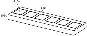
도 5b 는 모듈러 인클로져 내에 포함되어 있는 바와 같은 BAN 모듈 (450) 모듈의 일 실시예의 일 예를 도시한다. 도시된 바와 같이, BAN 모듈 (450) 은 베이스 패드들 (415a-415f), 스위치들 (420a-420f) (이 도면에서는 미도시), 분배 회로들 (421a 및 421b) (이 도면에서는 미도시), 및 로컬 제어기들 (425a 및 425) (이 도면에서는 미도시) 을 포함하여, 도 5a 의 컴포넌트들을 그 안에 포함하고 있는 직사각형 인클로져 (505) 를 포함할 수도 있다. 도시된 바와 같이, 전기 차량 (405) 의 이동의 방향으로 순차적으로 BAN 모듈 (450) 의 상부 표면 (455) 을 따라서 6 개의 베이스 패드들 (415a-415f) 을 볼 수도 있다. 다른 실시예에서, BAN 모듈 (450) 은 애플리케이션에 의해 결정된 바와 같은 임의의 형상의 모듈 컴포넌트로 포함되어 있을 수도 있다.FIG. 5B illustrates an example of one embodiment of a BAN module 450 module as contained within a modular enclosure. As shown, BAN module 450 includes
BAN 인클로져 (505) 는 표준 동적 무선 충전 시스템 (400) 내에 쉽게 삽입될 수도 있는 모듈러 컴포넌트를 생성하여, 위에서 논의된 바와 같이, 설치, 제거, 유지를 간소화하고, 연관된 비용들을 감소시키는데 이용될 수도 있다. 설치 및 제거가 간소화되고, 따라서 연관된 비용들이 감소될 수도 있으며, 여기서 모듈러 컴포넌트는 표준 형상이고 물리적 접속들은 최소화된다. 일 실시예에서, BAN 인클로져 (505) 는 인클로져 (505) 의 상부 표면 (510) 이 도로 (410) 의 상부 표면과 같은 평면에 있도록 도로 (410) 내에 설치될 것이다. 그러한 실시예에서, BAN 인클로져 (505) 의 상부 표면 (510) 은 도시된 바와 같이 베이스 패드들 (415a-415f) 의 상부 표면들을 노출시킬 수도 있거나, 베이스 패드들 (415a-415f) 의 상부 표면들을 커버할 수도 있다. 베이스 패드들 (415) 의 상부 표면들을 노출시킨 채로 두는 것은 간섭 또는 다른 문제들을 도입할 수도 있는 임의의 중간 엘리먼트들을 감소시킴으로써 베이스 패드들 (415) 에 의해 가능한 전력 전송을 증가시킬 수도 있다. 그러나, 베이스 패드들 (415) 의 상부 표면들을 노출시킨 채로 두는 것은 베이스 패드들 (415) 에 대한 손상의 위험을 증가시킬 수도 있다. 다른 실시예에서, BAN 인클로져 (505) 는 BAN 모듈 (450) 및 BAN 인클로져 (505) 의 어떤 부분도 도로 (410) 에 노출되지 않도록 도로 (410) 아래에 설치될 수도 있다.The
도 6 은 도관 (610) 및 인클로져 (605) 에 접속되는 도로 (410) 에서의 다수의 BAN 모듈 (450) 모듈들의 설치의 일 예를 도시한다. 도 6 은 페이지에 걸쳐 있는 도로 (410) 를 도시한다. 도로 (410) 의 중간은 BAN 모듈들 (450a 및 450b) 이 위치된 스트립이다. 도시된 바와 같이, BAN 모듈들 (450a 및 450b) 은 도로 (410) 내에 이미 설치되어 있으며, BAN 모듈 (450c) 이 도로 (410) 위에 보이며 BAN 모듈 (450b) 옆에 설치됨을 표시한다. 일부 실시예들에서, BAN 모듈 (450c) 아래에 보이는 바와 같이, BAN 모듈들 (450) 아래에 접속부 (615) 가 위치될 수도 있다. 다른 실시예에서, 접속부 (615) 는 BAN 모듈 (450) 측에 또는 설치에 도움이 되고 설치를 용이하게 하는 BAN 모듈 (450) 에 대한 임의의 다른 위치에 위치될 수도 있다. 백본 접속부 (615) 는 도로 (410) 에서 BAN 모듈 (450) 이 설치될 수도 있는 도관 (610) 에서 보인다. 일부 실시예들에서, 백본 접속부 (615) 는 백본 (430) 과 BAN 모듈 (450) 사이의 접속이 무선 (예를 들어, 유도 등) 인 경우 존재하지 않을 수도 있다. 도관 (610) 은 BAN 모듈들 (450) 아래에서 도로 (410) 의 길이를 따라 이어진다. BAN 모듈들 (450a-450c) 의 길이의 끝에서, 도관 (610) 은 도로의 측면으로 도로를 가로지르고 그 다음에 인클로져 (605) 에 대해 수직으로 이어진다.6 shows an example of the installation of a plurality of BAN module 450 modules on a
도 6 에 도시된 컴포넌트들은 동적 무선 충전 시스템 (400) 의 컴포넌트들이 도로 (410) 의 길게 뻗은 구간 (stretch) 을 따라서 설치될 수도 있는 방법의 일 예이다. 도로 (410) 의 측면에 따르는 인클로져 (605) 는 전력 공급기/인버터 (435), 전력 소스 (440), 및 분배 제어기 (445) 중 적어도 하나를 포함할 수도 있다. 위에서 설명된 바와 같이, 도관 (610) 은 인클로져 (605) 로부터 표면 아래로 그리고 도로 (410) 의 중심으로 이어지며, 중심 지점에서 꺽여서 주어진 거리에서 도로 (410) 의 길이에서 아래로 이어진다. 도관 (610) 은 백본 (430) 을 포함할 수도 있으며, 백본 (430) 에 의해, 인클로져 (605) 에서의 전력 공급기/인버터 (435) 및 전력 소스 (440) 로부터 설치된 BAN 모듈들 (450) 의 각각으로 전류가 전달될 수도 있다. 대안적으로, 도관 (610) 은 인클로져 (605) 내의 분배 제어기 (445) 와 다른 동적 무선 충전 시스템 (400) 컴포넌트들 사이의 통신들이 통신되는 통신 경로를 나타낼 수도 있다. 대안적인 실시예에서, 도관 (610) 은 백본 (430) 및 통신 경로들 양자 모두를 제공할 수도 있다.The components shown in FIG. 6 are examples of how the components of the dynamic
도 6 은 모듈러 BAN 모듈 (450) 모듈들을 이용하는데 수반되는 설치의 간단함의 표시를 제공한다. 동적 무선 충전 시스템 (400) 의 설치는 오직 3 개의 개개의 컴포넌트들: 분배 제어기 (445), 전력 소스 (440), 및 전력 공급기/인버터 (435) 를 포함하는 인클로져 (605), 백본 (430) 및 가능하게는 통신 와이어링을 포함하는 도관 (610), 및 BAN 모듈들 (450) 만을 설치하는 것을 수반할 수도 있다. 도로 (410) 아래와는 반대로 도로 (410) 옆에 인클로져 (605) 에 분배 제어기 (445), 전력 소스 (440), 및 전력 공급기/인버터 (435) 를 유지하는 것은 서비스 또는 유지보수의 필요 시에 이러한 컴포넌트들을 보다 액세스가능하게 함으로써 유지보수의 용이함을 유지할 수도 있다. 도로 (410) 아래에 도관 (610) 을 설치하는 것은 전력이 도로 (410) 아래의 시스템의 길이를 따라 흐르게 함으로써 BAN 모듈들 (450) 에 대한 접속의 용이함 및 추가적인 안전성을 제공할 수도 있으며, 여기서 돌발적인 노출은 제한되어야 한다. BAN 모듈 (450) 의 유지보수 및 설치 비용들은 접속부들이 최소화되는 경우에 감소될 수도 있고, BAN 모듈 (450) 의 컴포넌트들의 접속부들은 모듈 (450) 이 조립되거나 구성되는 때에 완료된다.6 provides an indication of the simplicity of the installation involved in using modular BAN module 450 modules. The installation of the dynamic
차량 패드 (406) 는 전기 차량 (405) 이 베이스 패드들 (415) 로부터 무선 전력을 수신하는 것을 가능하게 하는 전기 차량 (405) 의 장치를 지칭할 수도 있다. 일부 실시예들에서, 차량 패드 (406) 는 전기 차량 (405) 의 특정 포지션에 병치된 (co-located) 하나 이상의 코일들을 지칭할 수도 있다. 예를 들어, 차량 패드 (406) 는 전기 차량 (405) 상에서 실질적으로 동일한 포지션에 위치된 더블-D 및 직교 코일을 포함할 수도 있다. 각각 개개의 코일은, 다른 코일과 함께 위치될지라도, 다른 병치된 코일들과 독립적으로 그리고 동시에 동작하는 것이 여전히 가능할 수도 있다. 일부 실시예들에서, 차량 패드 (406) 를 형성하는 하나 이상의 코일들은 병치되기 보다는, 서로의 인근에 위치될 수도 있다. 차량 패드 (406) 는 DDQ 차량 패드일 수도 있어, 개개의 코일들 (더블-D 및 직교) 의 각각은 동일한 BAN 모듈 (450) 의 베이스 패드들 (415) 로부터 서로 독립적으로 그리고 동시에 무선 전력을 수신하고, 따라서 전기 차량 (405) 에 함께 전력을 협력하여 제공할 수 있다. 다른 실시예들에서, 차량 패드 (406) 는 전기 차량 (405) 으로의 무선 전력 전송을 가능하게 하는 베이스 패드들 (415) 과 커플링하는 하나 이상의 코일들을 구체적으로 지칭할 수도 있다.
다수의 차량 패드들 (406) 을 포함하는 실시예들에서, 각각의 차량 패드 (406) 는 모든 다른 차량 패드들 (406) 과 독립적으로 각각 동작할 수도 있다; 추가적으로, 각각의 차량 패드 (406) 는 하나 이상의 다른 차량 패드들 (406) 과 동시에 동작하는 것이 가능할 수도 있다. 일부 실시예들에서, 전기 차량 (405) 은 다수의 차량 패드들 (406) 을 가질 수도 있으며, 차량 패드들의 각각은 별개의 BAN 모듈 (450) 위에 있다. 예를 들어, 전기 차량 (405) 의 제 1 차량 패드 (406) 는 전기 차량 (405) 의 앞 바퀴들 근처에 설치될 수도 있고, 따라서 BAN 모듈 (450a) 위에 있을 수도 있으며, 한편 전기 차량 (405) 의 제 2 차량 패드 (406) 는 뒷 바퀴들 근처에 설치되고 BAN 모듈 (450b) 위에 있을 수도 있다. 그러한 실시예들에서, 각각의 차량 패드 (406) 는, 각각의 차량 패드들 (406) 의 개개의 위치 또는 전류 흐름과 상관없이, 전기 차량 (405) 이 전기 차량 (405) 에 의해 필요한 것으로 간주되는 차량 패드들 (406) 중 하나 또는 양자 모두로부터 전력을 수신할 수도 있도록 동작하도록 구성될 수도 있다. 단일 차량 패드 (406) 에서의 개개의 코일들에 대해 위에서 논의된 바와 같이, 하나 이상의 차량 패드들 (406) 은 필요하다면 양자 모두가 전기 차량 (405) 에 충전을 제공하도록 협력적인 방식으로 작동할 것이다.In embodiments including
도 7 은 도 4 의 개략도를 도시하며, 여기서 전기 차량 (405) 은 차량 패드 피치 (705) 를 갖는 2 개의 차량 패드들 (406a 및 406b) 을 포함하고, 베이스 패드 피치 (710) 가 또한 도시된다. 전기 차량 (405) 은 추가적으로 제어기 (407) 및 에너지 저장 디바이스 (408) 를 포함한다. 제어기 (407) 는 차량 패드들 (406a 및 406b) 양자 모두에 접속되고 에너지 저장 디바이스 (408) 에 더 접속되는 것으로 도시된다. 차량 패드 피치 (705) 는 중심에서부터 중심까지 차량 패드들 (406a 및 406b) 사이의 거리를 나타낸다. 베이스 패드 피치 (710) 는 중심에서부터 중심까지 베이스 패드들 (415) 사이의 사이의 거리를 나타낸다. 도 7 에 도시된 바와 같이, 베이스 패드 피치 (710) 는 연속하는 베이스 패드들 (415) 의 각각의 쌍 사이에 일관성을 보인다. 도 7 에 도시된 나머지 개개의 컴포넌트들은 도 4 에서의 컴포넌트들과 동일하고 다시 설명될 필요는 없다. 도 4 와 마찬가지로, 이동의 방향은 페이지를 가로지르며 왼쪽에서 오른쪽으로이다.Figure 7 shows a schematic view of Figure 4 wherein the
도 7 의 시스템의 기능성은 도 4 와 관련하여 설명된 기능성과 유사할 수도 있다. 차량 패드들 (406a 및 406b) 및 제어기 (407) 및 에너지 저장 디바이스 (408) 사이의 접속들은 또한 도 4 에서 위에서 설명된 것과 유사할 수도 있다. 추가적으로, 다수의 차량 패드들 (406) 을 갖는 시스템에서, 각각 개개의 차량 패드 (406) 는 전기 차량 (405) 의 다양한 컴포넌트들 및 시스템들에 상이한 방식으로 전력을 선택적으로 제공하도록 구성될 수도 있다. 예를 들어, 일 실시예에서, 하나 이상의 차량 패드들 (406) 의 각각은 동적 무선 충전 시스템 (400) 으로부터 에너지 저장 디바이스 (408) 를 재충전하는 능력을 최대화하도록 에너지 저장 디바이스 (408) (예를 들어, 배터리) 에 전력을 선택적으로 제공할 수도 있다. 대안적인 실시예에서, 하나 이상의 차량 패드들 (406) 중 제 1 차량 패드 (406a) 는 에너지 저장 디바이스 (408) (예를 들어, 배터리) 에 전력을 선택적으로 제공할 수도 있으며, 한편 차량 패드들 (406) 중 제 2 차량 패드 (406b) 는 전기 차량 (405) 의 전자부품 (이 도면에서는 미도시) 에 전력을 선택적으로 제공할 수도 있어, 전기 차량 (405) 의 전자 시스템들이 차량 패드 (406b) 로부터의 전력이 쉽게 이용가능하지 않을 수도 있는 시간들 동안 무선으로 수신된 전력으로부터 에너지를 인출하고 배터리 전력을 절약할 수도 있다. 예를 들어, 이는 에너지 저장 디바이스 (408) 가 용량이 있고 차량 패드들 (406) 로부터 무선으로 수신된 전력으로부터 전하를 수신할 수 없을 수도 있는 경우에 일어날 수도 있다. 그러한 예에서, 차량 패드들 (406) 은 에너지 저장 디바이스 (408) 가 완전 충전을 유지하고 수신된 전력을 낭비하지 않도록 동작 중에 있는 전기 시스템들에 수신된 전력을 공급하도록 다이렉팅될 수도 있다. 대안적인 실시예에서, 복수의 차량 패드들 (406) 중 하나 이상은 다른 차량 패드들 (406) 이 활성이고 무선 전력을 수신하는 동안에 선택적으로 활성화해제될 수도 있다. 위에서 논의된 바와 같이, 위의 옵션들 (예를 들어, 에너지 저장 디바이스 (408) 를 충전하는 것, 또는 차량 패드들 (406) 을 통해 수신된 전력을 이용하여 전기 차량의 전자 시스템들에 전력을 제공하는 것, 또는 하나 이상의 차량 패드들 (406) 을 활성화해제하는 것) 사이에서 선택하는 것은 오퍼레이터, 전기 차량 (405), 동적 무선 충전 시스템 (400), 및 전기 차량 (405) 이나 동적 무선 충전 시스템 (400) 에 수반되는 임의의 다른 디바이스나 엔티티 중 적어도 하나에 의해 수행될 수도 있다.The functionality of the system of FIG. 7 may be similar to the functionality described in connection with FIG. The connections between the
도 7 은 BAN 모듈 (450) 의 사이즈에 대한 차량 패드 피치 (705) 의 일 실시예를 도시한다. 위에서 논의된 바와 같이, BAN 모듈 (450) 은 각각의 로컬 제어기 (425) 가 임의의 주어진 순간에 오직 단일 베이스 패드 (415) 에만 전력을 제공할 수도 있도록 설계될 수도 있다. 따라서, 동적 무선 충전 시스템 (400) 및 전기 차량들 (405) 의 상호동작가능성 및 그것들의 차량 패드들 (406) 을 설계하는 경우, BAN 모듈 (450) 의 사이즈는 차량 패드 피치 (705) 에 기초하여 결정될 수도 있다. 일 실시예에서, 로컬 제어기 (425) 가 일 시간에 하나를 초과하는 베이스 패드 (415) 에 전류를 제공하는 것을 방지하는 것은 컴포넌트 레이팅들 및 비용들을 감소시키고 따라서 BAN 모듈 (450) 의 비용들을 감소시키기 위해 필요할 수도 있다. 이와 같이, BAN 모듈 (450) 은 2 개의 차량 패드들 (406) 이 절대 단일 BAN 모듈 (450) 위에 있지 않도록 사이즈가 정해질 수도 있다. 따라서, BAN 모듈 길이는 차량 패드 피치 (705) 보다 작을 수도 있다. 일부 실시예들에서, 이는 BAN 모듈 (450) 의 첫번째 베이스 패드 (415) 와 BAN 모듈 (450) 의 마지막 베이스 패드 (415) 사이의 거리가 연속하는 차량 패드들 (406) 사이의 피치보다 작다는 것을 의미할 수도 있다. 이에 따라, 전기 차량 (405) 의 연속하는 차량 패드들 (406) 은 상이한 BAN 모듈들 (450) 에 의해 각각 충전될 수도 있다. 다른 실시예들에서, BAN 모듈 (450) 의 임의의 2 개의 베이스 패드들 (415) 사이의 거리는 전기 차량 (405) 의 2 개의 차량 패드들 (406) 사이의 피치보다 작을 수도 있다. BAN 모듈 (450) 의 첫번째와 마지막 베이스 패드들 (415) 사이의 최대 거리의 그러한 사이즈 정하기는 동일한 차량 (405) 상의 2 개의 차량 패드들 (406) 이 동시에 동일한 BAN 블록으로부터 전력을 수신하지 않는 것을 보장할 수도 있다. 이에 따라, 베이스 패드 피치 (710) 및 베이스 패드 사이즈는 중요할 수도 있다. 도시된 예시적인 BAN 모듈 (450) 에서, 베이스 패드 사이즈 및 베이스 패드 피치 (710) 는 6 개의 베이스 패드들 (415) 을 포함하는 BAN 모듈 (450) 이 차량 패드 피치 (705) 보다 작은 전체 길이를 가지도록 결정될 수도 있다.FIG. 7 illustrates one embodiment of a
2 개의 차량 패드들 (406) 은 전기 차량 (405) 에 보다 큰 전력의 양들을 전송하려고 시도하는 경우에 이로울 수도 있다. 단일 차량 패드 (406) 로, 베이스 패드들 (415) 과 차량 패드 (406) 사이의 수직 거리에 걸쳐서 높은 전력 전송을 가능하게 하는 것은 전송 위치들에서의 보다 높은 플럭스 밀도들, 보다 큰 에너지, 또는 전력 집중을 요구할 수도 있으며, 이는 방출 문제들 및 효율 문제들을 야기할 수도 있다. 추가적으로, 전력 전송 중의 높은 에너지 또는 전력 집중들은 베이스 패드들 (415), 스위치들 (420), 분배 회로 (421), 로컬 제어기 (425), 및 베이스 차량 패드들 (406) 과 같은 수반되는 컴포넌트들이 보다 높게 레이팅될 것을 요구할 수도 있다. 적어도 제 2 차량 패드 (406) 를 추가하는 것은 플럭스 밀도들 및 결과적인 전력 요구사항들이 감소되고 적어도 2 개의 위치들에서 균등하게 그리고 동시에 적용되는 것을 가능하게 할 수도 있다. 추가적으로, 보다 많은 차량 패드들 (406) 을 추가하는 것은 BAN 모듈 (450) 컴포넌트들의 보다 나은 사용을 가능하게 할 수도 있는데, 다수의 차량 패드들 (406) 이 보다 많은 베이스 패드들 (415) 이 활성화되는 것을 요구할 수도 있고, 따라서 보다 많은 차량 패드들 (406) 에 대한 충전을 제공하기 위해 각각의 베이스 패드 (415) 가 요청될 수도 있음에 따라 보다 자주 BAN 모듈 (450) 내의 컴포넌트들을 사용할 수도 있기 때문이다. 다른 실시예에서, 동적 무선 충전 시스템 (400) 및/또는 분배 제어기 (445) 는 차량 패드들 (406a 및 406b) 의 각각에 분배되는 전력의 비율을 선택적으로 분배할 수도 있다. 이는 적어도 2 개의 차량 패드들에 총 전력을 제공하기 위해 베이스 패드들 (415) 의 적어도 2 개의 조합들에 대한 총 출력을 분배하는데 요구되는 플럭스 출력들 및 방출들을 절반으로 효과적으로 감소시킬 수도 있다.Two
도 7 에 도시된 예시적인 실시예에서, 차량 패드들 (406) 은 전기 차량 (405) 의 앞 차축과 뒤 차축 근처에 또는 앞 차축과 뒤 차축에 설치된다. 이러한 설치 지점들은 차량 패드들 (406) 의 물리적 공간 요구사항들 및 차량 패드들 (406) 이 서로 간섭을 야기하지 않도록 떨어진 거리에서 전력 방출들을 분배하기 위한 요구로 인해 실용적일 수도 있다. 일부 실시예들에서, 차량 패드 피치 (705) 는 약 2.5 미터일 수도 있다. 다른 실시예들에서, 차량 패드 피치 (705) 는 전기 차량 (405) 에 따라 1.75 미터와 같이 짧거나 4 미터와 같이 길 수도 있다.In the exemplary embodiment shown in FIG. 7,
위에서 논의된 바와 같이, BAN 모듈 (450) 내에서 설명된 병렬 전력 분배 구조는 단일 로컬 제어기 (425) 가 하나를 초과하는 베이스 패드 (415) 에 전력을 제공하는 것이 불가능함으로 인해 BAN 모듈 (450) 내의 로컬 제어기 (425) 가 동시에 적어도 2 개의 차량 패드들 (406) 에 전력을 제공하는 것을 제한할 수도 있다. 따라서, BAN 모듈 (450) 길이는 차량 패드 피치 (705) 의 길이보다 짧을 수도 있다. 추가적으로, BAN 모듈 (450) 의 설계는 비용 효과적이고 효율적인 시스템을 제작하는 것에 추가적으로 의존할 수도 있다. BAN 모듈 (450) 은 베이스 패드들 (415) 에 피드하는 전력 분배 컴포넌트들의 비용들 및 투자를 최적화하도록 최소 개수의 베이스 패드들 (415) 을 포함할 수도 있다. 예를 들어, 스위치 (420), 분배 회로부 (421), 및 로컬 제어기 (425) 를 갖는 단 하나의 단일 베이스 패드 (415), 또는 심지어 2 개의 베이스 패드들 (415) 로 BAN 모듈 (450) 을 구성하는 것은 비용 효율적이지 않을 것이다 (2 개의 베이스 패드들은 병렬 분배 구조로 인해 여전히 2 개의 스위치들 (420), 2 개의 분배 회로들 (421), 및 2 개의 로컬 제어기들 (425) 을 요구할 수도 있다). BAN 모듈 (450) 당 3 개 또는 4 개의 베이스 패드들 (415) 의 최소 양은 컴포넌트들의 비용들을 크게 최적화하지 않을 수도 있는데, 각각의 로컬 제어기 (425) 가 각각 BAN 모듈 (450) 당 오직 1 개 또는 2 개의 베이스 패드들 (415) 만을 제어할 수도 있기 때문이며, 그렇지만 이러한 설계는 베이스 패드 (415) 사이즈에 의존하여 적정한 BAN 모듈 (450) 길이를 초래할 수도 있으며, BAN 모듈 길이는 차량 패드 피치 (705) 보다 작을 가능성이 있다. 반면에, BAN 모듈 (450) 당 8 개의 베이스 패드들 (415) 은, 전력을 제어하고 분배하기 위해 각각의 로컬 제어기 (425) 에 4 개의 베이스 패드들 (415) 을 제공하고 각각의 BAN 모듈 (450) 이 보다 비용 효율적일 수도 있으면서, 2.5 미터의 차량 패드 피치 (705) 를 초과할 수도 있도록 BAN 모듈 (450) 길이를 상당히 증가시킬 수도 있다. 대안적으로, 차량 패드 피치 (705) 보다 작은 길이로 BAN 모듈 (450) 당 8 개의 베이스 패드들 (415) 을 수용하기 위해 베이스 패드들 (415) 의 사이즈를 감소시키는 것은 전력 전송 시에 베이스 패드 (415) 효율성을 감소시키고 따라서 베이스 패드 (415) 및 BAN 모듈 효율과 비용 효율성을 감소시킬 수도 있다. 따라서, 일 실시예의 일 예에서, 6 개의 베이스 패드들 (415) 은 각각의 BAN 모듈 (450) 에 설치하기 위해 이상적인 개수의 베이스 패드들 (415) 일 수도 있고, 컴포넌트 비용들과 레이팅들, 현재 요구사항들, 상호 인덕턴스들, 및 미터당 패드들 사이에 최적의 비교를 제공할 수도 있는 한편, 차량 패드 피치 (705) 의 제한들 내로 적정한 BAN 모듈 (450) 길이를 유지한다. 차량 패드 피치 (705) 가 2.5 m 보다 크거나 작을 수도 있는 다른 실시예에서는, 차량 패드 피치 (705) 의 제약들을 만족시키기 위해 보다 많거나 보다 적은 수량의 베이스 패드들 (415) 이 BAN 모듈 (450) 에 설치될 수도 있다.As discussed above, the parallel power distribution architecture described within the BAN module 450 is advantageous because the single local controller 425 is not capable of providing power to more than one
2 개 이상의 차량 패드들 (406) 을 포지셔닝시키는 경우, 차량 패드들 (406) 사이의 피치는 주어진 순간 또는 포지션에서 베이스 패드들 (415) 과 차량 패드들 (406) 사이의 결합된 총 전력 전송의 효과에 영향을 줄 수도 있다. 일부 실시예들에서, 차량 패드들 (406) 은 베이스 패드 피치 (710) 의 배수와 동일한 차량 패드 피치 (705) 로 이격되는데, 예를 들어, 차량 패드 피치 (705) 는 베이스 패드 피치 (710) 의 4 배일 수도 있다. 차량 패드 피치 (705) 대 베이스 패드 피치 (710) 에서의 이러한 비율로, 차량 패드들 (406) 은 베이스 패드들 (415) 위에서의 그것들의 위치들에 대해 항상 조정된다. 예를 들어, 제 1 차량 패드 (406b) 가 베이스 패드 (415a) 위에 있고 차량 패드 피치 (705) 가 베이스 패드 피치 (710) 의 4 배인 경우, 차량 패드 (406a) 는 4 개의 베이스 패드들만큼 떨어진 베이스 패드 (415e) 위의 동일한 지점에 있다. 따라서, 2 개의 차량 패드들 (406) 은 동시에 베이스 패드들 (415) 의 동일한 지점들 위에 있는 경우 낮은 전력 전송과 높은 전력 전송의 동일한 지점들을 가질 것이다. 이에 따라, 차량 패드들 (406) 로부터의 결합된 전력 전송 양자 모두는 많이 변하며, 여기서 그것들은 동일한 시간에 최대 전력 전송을 각각 제공하고 (예를 들어, 차량 패드들 (406) 양자 모두는 그것들의 각각의 베이스 패드들 (415) 의 가장자리들 위에 있을 수도 있다), 동시에 최소 전력 전송을 제공할 수도 있다 (예를 들어, 차량 패드들 (406) 양자 모두는 그것들의 각각의 베이스 패드들 (415) 의 중심들 위에 있을 수도 있다). 따라서, 결합된 차량 패드들 (406) 에 대한 전력 전송 곡선은 차량 패드들 (406) 양자 모두가 그것들의 최대치들을 제공하는 경우에 최고치들을, 그리고 차량 패드들 (406) 양자 모두가 그것들의 최소치들을 제공하는 경우에 최저치들을 가지고, 부드러운 전력 전송을 제공하지 않을 수도 있다.When positioning two or
다른 실시예에서, 차량 패드 피치 (705) 사이의 비율은 베이스 패드 피치 (710) 더하기 베이스 피치의 절반의 배수 (예를 들어, 베이스 패드 피치 (710) 의 4.5 배) 와 동일하게 달라질 수도 있어, 차량 패드들 (406) 은 주어진 순간에 전력을 수신하는 경우에 베이스 패드들의 상이한 지점들 위에 있고, 따라서 상호보완적인 방식으로 동작한다 - 하나가 최대 커플링 포지션에 있는 경우, 다른 것은 최소 커플링 포지션에 있다. 따라서, 차량 패드 (406a) 가 (그것의 베이스 패드 (415) 의 가장자리 위에서) 그것의 최대 전력 전송을 제공할 수도 있는 경우, 차량 패드 (406b) 는 (그것의 베이스 패드 (415) 의 중심 위에서) 그것의 최소치를 제공할 수도 있고, 차량 패드 (406a) 가 (이제 베이스 패드 (415) 의 중심 위에서) 최소 전력 전송을 제공하는 경우, 차량 패드 (406b) 는 (베이스 패드 (415) 의 가장자리 위에서) 그것의 최대치를 제공할 수도 있다. 따라서, 이러한 실시예의 최대 전력 전송들은 달성할 수 있는 최대치가 아닐 수도 있으나, 전력 전송들은 부드러울 수도 있으며, 여기서 차량 패드들 (406) 은 최대 전력 제공과 최소 전력 제공을 번갈아 하고, 베이스 패드 피치 (710) 의 정수 비율과 동일한 차량 패드 피치 (705) 로 이격되는 차량 패드들 (406) 에 일어날 수도 있는 전력 전송 시의 동일한 피크들과 밸리들을 겪지 않는다. 이에 따라, 이상적인 차량 패드 피치 (705) 및 베이스 패드 피치 (710) 비율은: In another embodiment, the ratio between the vehicle pad pitches 705 may be the same as the
[차량 패드 피치 = (N + 0.5) * 베이스 패드 피치] 와 같다.[ Vehicle pad pitch = (N + 0.5) * Base pad pitch ].
이상적으로, BAN 모듈들 (450) 에서의 베이스 패드들 (415) 은 BAN 모듈들 (450) 사이에서 임의의 단절들 및 전환 (transition) 들 없이 중첩하는 것이 가능할 것이다. 그러나, 차량 패드들 (406) 은 BAN 모듈들 (450) 사이에서 전환해야 하고, 이에 따라, 베이스 패드들 (415) 과 차량 패드들 (406) 사이의 전력 전송은 전환들 내내 유지되어야 한다. BAN 모듈 (450) 의 일부 실시예들에서, BAN 모듈 (450) 의 끝부분들에서의 베이스 패드들 (415) 은 BAN 모듈 (450) 의 끝부분들에 있지 않은 베이스 패드들 (415) 과는 상이한 설계일 수도 있다. 일부 실시예들에서, BAN 모듈들 (450) 의 끝부분들에 위치된 베이스 패드들 (415) 은 차량 패드들 (406) 중 적어도 하나가 BAN 모듈들 (450) 사이에서 전환하는 경우에 결합된 차량 패드들 (406) 로부터의 총 전력 출력이 충분히 높도록 설계될 수도 있다. BAN 전환에서 결합된 차량 패드들 (406) 로부터의 충분히 높은 전력 출력은 BAN 모듈들 (450) 사이에서 전환하지 않는 경우에 획득된 총 전력 출력의 80% 의 결합된 전력 전송을 포함할 수도 있다. 대안적으로, 충분히 높은 전력 출력은 50% 이상의 결합된 전력 출력을 포함할 수도 있다. 일부 실시예들에서, BAN 모듈 (450) 의 끝부분의 베이스 패드들 (415) 은 BAN 모듈 (450) 의 중간에 있는 베이스 패드들 (415) 보다 w작은 사이즈이도록 설계될 수도 있다.Ideally, the
끝부분의 베이스 패드들 (415) 은 BAN 모듈들 (450) 의 끝부분의 베이스 패드들 (415) 과 차량 패드들 (406) 사이의 커플링을 보장하여 BAN 모듈들 (450) 의 풀 사이즈 베이스 패드들 (415) 과 유사한 전력 전송을 제공하도록 설계될 수도 있다. 일부 실시예들에서, 끝부분의 베이스 패드들 (415) 의 설계는 베이스 패드 피치의 2 배의 풀 사이즈 베이스 패드 (415) 사이의 거리에 기초할 수도 있는데, 이는 BAN 모듈 (450a) 의 마지막 풀 사이즈 베이스 패드 (415) 와 BAN 모듈 (450b) 의 첫번째 풀 사이즈 베이스 패드 (415) 사이의 거리가 2 개의 풀 사이즈 베이스 패드 피치들과 동일하다는 것을 의미한다. 이에 따라, 끝부분의 베이스 패드들 (415) 과 다른 베이스 패드들 (415) 사이의 크로스-커플링 및 다른 잠재적인 해로운 영향들을 최소화하도록 끝부분의 베이스 패드들 (415) 을 설계하기 위해, 끝부분의 베이스 패드들 (415) 은 풀 사이즈 베이스 패드들 (415) 과 비교하여 충분한 커플링을 갖지 않도록 비실용적으로 작을 수도 있다.The
일부 실시예들에서, 끝부분의 베이스 패드들 (415) 의 설계는 베이스 패드 피치의 3 배의 풀 사이즈 베이스 패드 (415) 사이의 거리에 기초할 수도 있는데, 이는 BAN 모듈 (450a) 의 마지막 풀 사이즈 베이스 패드 (415) 와 BAN 모듈 (450b) 의 첫번째 풀 사이즈 베이스 패드 (415) 사이의 거리가 3 개의 풀 사이즈 베이스 패드 피치들과 동일하다는 것을 의미한다. 여기서, 다른 베이스 패드들 (415) 에 대한 크로스-커플링 및 다른 잠재적인 해로운 영향들을 최소화하도록 설계된 끝부분의 베이스 패드들 (415) 은 BAN 모듈들 (450) 사이의 전환 내내 풀 사이즈 베이스 패드들 (415) 과 비교하여 충분한 커플링을 유지하도록 사이즈가 정해지고 이격될 수도 있다.In some embodiments, the design of the
일부 실시예들에서, 끝부분의 베이스 패드들 (415) 의 설계는 베이스 패드 피치의 4 배의 풀 사이즈 베이스 패드 (415) 사이의 거리에 기초할 수도 있는데, 이는 BAN 모듈 (450a) 의 마지막 풀 사이즈 베이스 패드 (415) 와 BAN 모듈 (450b) 의 첫번째 풀 사이즈 베이스 패드 (415) 사이의 거리가 4 개의 풀 사이즈 베이스 패드 피치들과 동일하다는 것을 의미한다. 여기서, 다른 베이스 패드들 (415) 에 대한 크로스-커플링 및 다른 잠재적인 해로운 영향들을 최소화하도록 설계된 끝부분의 베이스 패드들 (415) 은 BAN 모듈 (450) 전환 내내 불충분한 커플링을 갖도록 사이즈가 정해지고 이격될 수도 있으며, 여기서 끝부분의 베이스 패드들 (415) 이 전환 근처에서 중첩하지 않는 곳에 빈 공간이 존재할 수도 있다.In some embodiments, the design of the
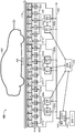
도 8 은 2 개의 연속하는 BAN 모듈들 (450) 의 예시적인 실시예들의 개략적이고 대응하는 투시도를 도시한다. 위에서 논의된 바와 같이, BAN 모듈들 (450) 의 각각은 복수의 베이스 패드들 (415), 복수의 스위치들 (420), 분배 회로들 (421), 및 복수의 로컬 제어기들 (425) 을 포함한다. 구체적으로, BAN 모듈 (450a) 은 베이스 패드들 (415a-415f), 스위치들 (420a-420f), 분배 회로들 (421a 및 421b), 및 로컬 제어기들 (425a 및 425b) 을 포함한다. BAN 모듈 (450b) 은 베이스 패드들 (415g-415l), 스위치들 (420g-420l), 분배 회로들 (421c 및 421d), 및 로컬 제어기들 (425c 및 425d) 을 포함한다. 각각의 로컬 제어기 (425a 및 425b) 는 각각 분배 회로 (421a 및 421b) 에 접속되며, 분배 회로는 BAN 모듈 (450a) 의 스위치들 (420) (로컬 제어기 (425a) 로의 스위치들 (420a, 420c, 및 420e), 로컬 제어기 (425b) 로의 스위치들 (420b, 420d, 및 420f)) 을 통해 각각의 로컬 제어기 (425a 및 425b) 를 베이스 패드들 (415) 중 절반 (베이스 패드들 (415a, 415c, 및 415e) 을 로컬 제어기 (425a) 에, 베이스 패드들 (415b, 415d, 및 415f) 을 로컬 제어기 (425b) 에) 에 접속시킨다. 유사한 접속 구성이 BAN 모듈 (450b) 에 대해 적용된다. BAN 모듈들 (450) 은 중첩하는 배향으로 있는 베이스 패드들 (415) 을 보여 줌으로써 다른 도면들에서의 묘사들과는 상이하다. 이러한 변화는 단지 BAN 모듈 (450) 내의 베이스 패드들 (415) 의 레이아웃의 추가적인 실시예를 제시하고자 하는 것이고, 제한하고자 하는 것은 아니다. BAN 모듈들 (450) 의 끝부분들에 있지 않은 각각의 베이스 패드 (415) 는 2 개의 다른 베이스 패드들 (415) 과 중첩할 수도 있는데 반해, BAN 모듈들 (450) 의 끝부분들에 있는 2 개의 베이스 패드들은 오직 1 개의 다른 베이스 패드 (415) 와 중첩할 수도 있다. 베이스 패드들 (415) 의 중첩하는 레이아웃은 베이스 패드들 (415), 스위치들 (420), 분배 회로들 (421), 또는 로컬 제어기들 (425) 의 전기 접속들 또는 레이아웃에 영향을 주지 않을 수도 있다. 개략도는 각각의 베이스 패드 (415) 가 후속하는 베이스 패드 (415) 에 의해 적어도 부분적으로 중첩되는 것을 도시한다. 예를 들어, 이동의 방향에서 BAN 모듈 (450a) 에서 첫번째 베이스 패드 (415) 인 베이스 패드 (415a) 는 베이스 패드 (415b) 에 의해 중첩되는 것으로 도시되는데 반해, 415b 는 베이스 패드 (415a) 에 의해 중첩하고 415c 에 의해 중첩하는 것으로 도시된다. 이는 베이스 패드 (415f) 가 BAN 모듈 (450a) 의 마지막 베이스 패드 (415) 이기 때문에 베이스 패드 (415f) 가 베이스 패드 (415e) 에 중첩하나 다른 베이스 패드 (415) 에 의해 중첩되지 않는 것으로 보일 때까지 BAN 모듈 (450a) 에 걸쳐 계속된다. 유사한 레이아웃이 BAN 모듈 (450b) 및 그것의 베이스 패드들 (415g-415l) 에 적용된다. 일부 실시예들에서, 인접한 BAN 모듈들 (450) 의 가장자리들에서의 베이스 패드들 (415) 은 서로 중첩하지 않고 대신에 엔드-투-엔드 (end-to-end) 로 설치될 수도 있다. 그러한 실시예에서는, 위에서 설명된 바와 같이, BAN 모듈 (450) 의 끝부분들에서의 베이스 패드들 (415) 은 오직 1 개의 다른 베이스 패드 (415) 와 중첩할 수도 있다. 다른 실시예에서, 인접한 BAN 모듈들 (450) 의 가장자리들에서의 베이스 패드들 (415) 이 서로 중첩하여, BAN 모듈 (450) 이 다른 BAN 모듈 (450) 과 중첩할 수도 있다. 이러한 실시예에서, BAN 모듈 (450) 의 끝부분들에서의 베이스 패드들 (415) 은, 끝부분의 베이스 패드 (415) 와 동일한 BAN 모듈 (450) 로부터의 베이스 패드 및 인접한 BAN 모듈 (450) 의 끝부분의 베이스 패드 (415) 인, 하나를 초과하는 다른 베이스 패드 (415) 와 중첩할 수도 있다. 도시된 바와 같이, BAN 모듈들 (450) 의 각각의 컴포넌트들은 분배 경로들을 표시하기 위해 음영 처리될 수도 있다 (예를 들어, 로컬 제어기 (425), 로컬 제어기 (425) 에 의해 제어되거나 로컬 제어기 (425) 에 커플링된 스위치들 (420), 및 스위치들 (420) 에 커플링된 베이스 패드들 (415) 은 공통 접속들 및 공유 전력 경로를 표시하기 위해 유사하게 음영 처리될 수도 있다).FIG. 8 shows a schematic and corresponding perspective view of exemplary embodiments of two consecutive BAN modules 450. As discussed above, each of the BAN modules 450 includes a plurality of
위에서 도시된 BAN 모듈들 (450a 및 450b) 의 개략도는 설치물에서 위쪽의 베이스 패드들 (415) 에서부터 아래로 내려다보며 뷰잉될 수도 있는 베이스 패드들 (415a-415l) 의 레이아웃의 투시도의 일 예이다. 위에서 논의된 바와 같이, BAN 모듈들 (450) 의 각각은 6 개의 베이스 패드들 (415) (BAN 모듈 (450a) 에 있어서는 415a-415f 그리고 BAN 모듈 (450b) 에 있어서는 415g-415l) 을 포함한다. 투시도는 중첩하는 베이스 패드들 (415) 의 다른 뷰를 도시한다. 이러한 뷰는 선행하는 베이스 패드들 (415) 에 중첩하는 후속하는 베이스 패드들 (415) 의 중첩하는 패턴/속성을 보다 명확하게 표시한다. 도시된 실시예는 가장자리 베이스 패드들 (415) 이 엔드-투-엔드인 인접한 BAN 모듈들 (450a 및 450b) 을 갖는다. 일부 실시예들에서는, 본원에서 도시된 바와 같이, BAN 모듈 (450) 의 가장자리들에서의 베이스 패드들 (415) 은 2 개 이상의 베이스 패드들 (415) 에 중첩하는 베이스 패드들 (415) 보다 작은 사이즈일 수도 있다. 다른 실시예에서, BAN 모듈 (450) 의 모든 베이스 패드들 (415) 은 동일한 사이즈일 수도 있다. 일부 다른 실시예들에서, BAN 모듈 (450) 의 베이스 패드들 (415) 은 상이한 형상들, 치수들, 또는 사이즈들일 수도 있다. 위에서 논의된 바와 같이, BAN 모듈 (450) 의 각각의 베이스 패드들 (415) 은 분배 경로들을 표시하기 위해 음영 처리될 수도 있다.A schematic diagram of the
일부 실시예들에서는, 본원의 도 8 에서 도시된 바와 같이, BAN 모듈 (450) 의 끝부분 중 어느 하나의 베이스 패드들 (415) 은 2 개의 다른 베이스 패드들 (415) 과 중첩하는 BAN 모듈 (450) 내의 나머지 베이스 패드들 (415) 보다 작은 사이즈일 수도 있다. 일부 실시예들에서, 이러한 끝부분의 베이스 패드들 (415) 은 BAN 모듈들 (450) 사이에서의 부드러운 전환을 제공하도록 중간의 베이스 패드들 (415) 의 사이즈의 절반일 수도 있다. 다른 실시예에서, 끝부분의 베이스 패드들 (415) 은 중심의 베이스 패드들 (415) 의 임의의 분수 길이일 수도 있다.8, any one of the
도 9 는 베이스 패드 활성화 시퀀스 (900) 의 일 예의 다양한 베이스 패드 활성화 시퀀스 단계들 (905-909) 의 투시도를 도시한다. 각각의 시퀀스 단계 (905-909) 는 동일한 베이스 패드 레이아웃 및 구성을 이용하나, 활성 베이스 패드들 (415) 의 상이한 조합들을 서술한다. 여기서 서술된 BAN 모듈 (450) 실시예는 다른 도면들에서 도시된 6 개의 베이스 패드들 (415) 대신에 8 개의 베이스 패드들 (415) 을 포함함으로써 다른 도면들에서의 BAN 모듈들 (450) 과는 다를 수도 있다. 이 실시예는 대안적인 옵션을 제시하고자 하고, BAN 모듈 (450) 의 서술들 중 어느 것도 제한하려는 것은 아니다.FIG. 9 shows a perspective view of various base pad activation sequence steps 905-909 of an example of a base pad activation sequence 900. Each sequence step 905-909 utilizes the same base pad layout and configuration, but describes different combinations of
각각의 시퀀스 단계 (905-909) 의 베이스 패드 레이아웃은 페이지를 가로지르며 왼쪽으로부터 오른쪽으로 이동하는, 도로 (410) 를 따라 설치된 하나의 BAN 모듈 (450) 로부터의 베이스 패드들 (415) 을 나타낼 수도 있다. 각각의 베이스 패드들 (415a-415h) 은 이동의 방향으로 순차적으로 배열되는 것으로 도시된다. 각각의 베이스 패드 (415) 는 가능한 경우 선행하는 베이스 패드들 (415) 및 후속하는 베이스 패드들 (415) 과 중첩한다. 교번하는 베이스 패드들 (415) 은 동일한 로컬 제어기 (425) 및 분배 회로 (421) 에 접속되거나 동일한 로컬 제어기 (425) 및 분배 회로 (421) 에 의해 제어될 수도 있고 따라서 베이스 패드들 (415) 의 세트들이 한 번에 오직 하나의 활성화된 베이스 패드를 가질 수도 있는 공유 전력 분배 경로들을 갖는 베이스 패드들 (415) 을 표시하기 위해 교번하는 방식으로 음영 처리될 수도 있다. 추가적으로, 각각의 단계 (905-909) 는 2 개의 방향들: 시계방향 또는 반시계방향 중 하나로 베이스 패드들 (415) 포인트의 상이한 조합들 상에 화살표들을 도시할 수도 있다. 시퀀스 단계들 (906-909) 은 또한 2 개의 박스들 (910a 및 910b) 을 도시하며, 각각의 박스 (910) 는 복수의 차량 패드들 (406) 중 하나에 전력 전송을 제공하기 위한 각각의 상이한 단계 (906-909) 에 대한 베이스 패드들 (415) 의 상이한 조합을 포함한다.The base pad layout of each sequence step 905-909 may represent
시퀀스 (900) 는 다수의 BAN 모듈들 (450) 의 베이스 패드들 (415) 과 차량 패드들 (406) 사이의 전력 전송들을 조정할 시에 이로울 수도 있다. 베이스 패드들 (415) 을 활성화시키는 시퀀스 (900) 를 따름으로써, 동적 무선 충전 시스템 (400) 은 단일 차량 패드에 최대 전력을 제공할 수도 있다. 효과적인 시퀀스 (900) 를 따르는 것은 가능한 가장 부드러운 전력 전송을 보장하도록 다양한 차량 패드들 (406) 에 대한 전력 전송을 조정하는 것을 수반할 수도 있다. 시퀀스 (900) 는, 위에서 설명된 바와 같은 차량 패드 피치 (705) 와 베이스 패드 피치 (710) 사이의 이상적인 비율로 조합하여, 가능한 가장 일관되고 효율적인 전력 전송을 제공할 수도 있다.The sequence 900 may be advantageous in coordinating the power transfers between the
시퀀스 (900) 는 개개의 단계들 (예를 들어, 906-909) 의 조합일 수도 있으며, 여기서 베이스 패드들 (415) 의 다양한 조합들은 주어진 순간에 차량 패드들 (406) 에 효율적인 전력 전송을 할 수 있는 베이스 패드들 (415) 만을 활성화시킴으로써 효과적이고 효율적인 전력의 전송을 제공하도록 활성화될 수도 있다. 개개의 단계들은 상이한 시간들에 상관될 수도 있고, 시퀀스는 경과된 시간 또는 차량 포지션에 기초하여 단계들 사이에서 반복할 수도 있다. 일 실시예에서, 시퀀스 (900) 의 시퀀스 (900) 및/또는 단계들은 분배 제어기 (445) 중 하나에 의해 제어될 수도 있다. 예를 들어, 분배 제어기 (445) 는 차량 패드들 (406) 을 갖는 전기 차량 (405) 과 통신할 수도 있고, 전기 차량 (405) 의 방향 및 속도를 결정할 수도 있다. 이러한 컴포넌트들을 이용하여, 분배 제어기 (445) 는 전기 차량 (405) 으로부터 수신된 파라미터들에 기초하여 미리 결정된 시퀀스 (900) 를 활성화시키거나 새로운 시퀀스 (900) 를 전개할 수도 있다. 이러한 파라미터들은 적어도: 차량 패드들 (406) 의 개수, 차량 패드 피치 (705), 차량의 속도, 차량의 방향, 차량의 현재 충전, 차량의 전류 부하, 또는 차량의 전류 요구 중 적어도 하나일 수도 있다. 분배 제어기 (445) 는 전기 차량 (405) 의 요구사항들 및 파라미터들에 맞춰진 시퀀스 (900) 를 전개할 수도 있고, 전기 차량 (405) 의 파라미터들에 기초하여 시퀀스 (900) 에 걸쳐 반복할 수도 있다. 다른 실시예에서, 분배 제어기 (445) 는 전기 차량 (405) 의 파라미터들에 기초하여 복수의 미리 결정된 시퀀스들 (900) 중 하나를 선택하고 시퀀스 (900) 에 걸쳐 반복할 수도 있다.The sequence 900 may be a combination of individual steps (e.g., 906-909), where various combinations of
도 9 는 복수의 차량 패드들 (406) 을 갖는 지나가는 전기 차량 (405) 에 대해 일정한 전류 흐름 방향들을 가지며 (예를 들어, 여기서 베이스 패드 (415) 를 통한 전류 흐름 방향은, 활성화되는 다른 베이스 패드들의 조합과 상관없이, 상이한 스테이지들에서 일정하게 유지된다) 연속하는 방식으로 중첩하는 베이스 패드들 (415) 을 활성화시키기 위한 (예를 들어, 여기서 각각의 베이스 패드 (415) 는 이동의 방향에서 연속하여 교대로 활성화된다) 시퀀스 (900) 의 실시예를 도시한다. 단계들 (906-909) 이 차량 패드들 (406) 의 각각에 대해 주어진 순간에 활성인 2 개의 베이스 패드들 (415) 만을 보여주나, 다른 실시예들은 임의의 방향으로의 전류 흐름을 갖는 주어진 순간에 활성인 임의의 개수의 베이스 패드들 (415) 을 가질 수도 있다. 시퀀스 단계들 (906-909) 의 각각은 활성화 시퀀스 (900) 에서 단일 스테이지 또는 단계를 나타낼 수도 있고, 2 개의 차량 패드들 (406) 을 갖는 전기 차량 (405) 이 도면의 베이스 패드들 (415a-415h) 위로 이동할 때 어떤 조합의 베이스 패드들 (415) 이 해당 스테이지에서 활성화될 것인지 그리고 그 시간에 활성인 베이스 패드 (415) 의 각각을 통해서 어떤 방향으로 전류가 흐를 수도 있는지를 표시한다. 시퀀스 단계들 (906-909) 에서 베이스 패드들 (415) 의 조합들에서 도시된 화살표는 화살표를 갖는 베이스 패드 (415) 가 화살표의 방향으로 활성인 것을 표시하여 베이스 패드 (415) 를 통한 전류 흐름의 방향을 표시하는 것을 표시할 수도 있다. 박스들 (910) 은, 전류 흐름 방향 화살표들과 유사하게, 베이스 패드들 (415) 의 어떤 조합이 주어진 순간에 활성인지를 표시할 수도 있다. 박스들 (910) 은 또한 차량 패드들 (406a 및 406b) 이 BAN 모듈 (450) 위로 지나가고 전기 차량 (405) 에 부드럽고 일정한 전력 전송을 제공하기 위해 시퀀스 (900) 에서 베이스 패드들 (415) 이 활성일 것을 요구한다고 표시할 수도 있다.9 shows that the current flow direction through the
단계 (905) 는 모든 베이스 패드들 (415a-415h) 이 활성이고 반시계 방향으로 전류 흐름을 갖는다는 것을 표시하는 레이아웃의 일 예일 수도 있다. 시퀀스 단계들 (906-909) 은 지나가는 전기 차량 (405) 에 무선 전력을 제공하기 위한 베이스 패드 활성화 시퀀스 (900) 의 일 예의 실제 단계들 또는 스테이지들을 서술할 수도 있다. 시퀀스 단계들 (906-909) 의 각각에 있어서, 상이한 조합들의 베이스 패드들 (415) 이 그것들 위에 그려진 화살표들을 가질 수도 있다. 단계들 (906-909) 은 전기 차량 (405) 이 도로 (410) 아래쪽으로 주행할 때에 시퀀스 (900) 의 연이은 반복들을 나타낸다.Step 905 may be an example of a layout indicating that all
예를 들어, 단계 (906) 는 전기 차량 (405) 이 일 포지션에 있는 경우에 활성화된 베이스 패드들 (415) 을 표시할 수도 있으며, 전기 차량 (405) 은 적어도 2 개의 차량 패드들 (406) 을 갖는다. 따라서, 906 은 반시계방향을 가리키는 화살표를 각각 갖는 베이스 패드들 (415a 및 415g) 을 도시하며, 한편 베이스 패드들 (415b 및 415f) 은 시계방향을 가리키는 화살표를 갖는다. 베이스 패드들 (415a 및 415b) 은 전력을 전송하기 위해 차량 패드 (406b) (이 도면에서는 미도시) 와 커플링할 수도 있고, 한편 베이스 패드들 (415f 및 415g) 은 전력을 전송하기 위해 차량 패드 (406a) (이 도면에서는 미도시) 와 커플링할 수도 있다. 단계 (906) 에서의 박스들 (910b 및 910a) 은 각각 베이스 패드들 (415a 및 415b) 및 베이스 패드들 (415f 및 415g) 주위에 형성될 수도 있다. 단계 (907) 는 베이스 패드들 (415b 및 415f) 은 시계방향을 가리키는 화살표를 각각 가질 수도 있고, 한편 베이스 패드들 (415c 및 415g) 은 반시계방향을 가리키는 화살표를 각각 갖는다는 것을 보여주며, 여기서 베이스 패드들 (415b 및 415c) 은 차량 패드 (406b) 와 커플링하고 베이스 패드들 (415f 및 415g) 은 차량 패드 (406a) 와 커플링할 수도 있다. 단계 (907) 에서 박스 (910b) 는 베이스 패드들 (415b 및 415c) 주위에 있을 수도 있고, 박스 (910a) 는 베이스 패드들 (415f 및 415g) 주위에 있을 수도 있다. 시퀀스 단계 (908) 는 시계방향을 가리키는 화살표를 각각 갖는 베이스 패드들 (415b 및 415h) 을 가지고, 한편 베이스 패드들 (415c 및 415g) 은 시계방향을 가리키는 화살표를 각각 갖는다. 베이스 패드들 (415b 및 415c) 은 그것들을 포함하는 박스 (910b) 에 의해 표시된 차량 패드 (406b) 와 커플링하고자 할 수도 있고, 415g 및 415h 는 그것들을 포함하는 박스 (910a) 를 갖는 차량 패드 (406a) 와 커플링하고자 할 수도 있다. 마지막으로, 단계 (909) 는 반시계방향 화살표를 갖는 베이스 패드 (415c) 및 시계방향 화살표를 갖는 베이스 패드 (415d) 를 보여주고, 양자 모두는 차량 패드 (406b) 와 커플링할 수도 있고, 한편 반시계방향 화살표를 갖는 베이스 패드 (415g) 및 시계방향 화살표를 갖는 베이스 패드 (415h) 는 차량 패드 (406a) 와 커플링할 수도 있다. 박스 (910b) 는 베이스 패드들 (415c 및 415d) 주위에 도시되고, 한편 박스 (910a) 는 베이스 패드들 (415g 및 415h) 을 포함할 수도 있다. 일부 실시예들에서, 전체 시퀀스 (900) 에 추가적인 단계들이 포함될 수도 있다. 다른 실시예들에서는, 도 9 에 의해 나타내어지는 시퀀스 (900) 에 보다 적은 단계들이 포함될 수도 있다. 도 9 에 도시된 단계들/스테이지들의 개수는 일 예를 위한 것이고 제한하기 위한 것이 아니다.For example, step 906 may display activated
도 10 은 도로 (410) 를 따르는 베이스 패드들 (415) 의 중첩하는 레이아웃의 일 예의 투시도를 도시한다. 도로 (410) 는 도로 (410) 의 이동의 방향으로 x-축에 대응할 수도 있고, 한편 도로 (410) 의 폭은 y-축을 따를 수도 있고, (이 도면에서는 도시되지 않은, 전기 차량 (405) 에 부착된) 차량 패드들 (406a 및 406b) 은 그것들이 동적 무선 충전 시스템 (400) 의 일 실시예에 존재할 수도 있을 때에 z-축에서 베이스 패드들 (415) 위의 거리 (z) 에 있는 것으로 도시될 수도 있다. 차량 패드 (406b) 는 대부분 베이스 패드 (415a) 위에 도시될 수도 있고, 한편 차량 패드 (406a) 는 대부분 베이스 패드 (415e) 위에 도시될 수도 있다. 차량 베이스 패드들 (406a 및 406b) 은 차량 패드 피치 (705) 에 의해 나타내어진, 서로 떨어져 있는 일정 거리에 있을 수도 있다. 베이스 패드들 (415a-415h) 은 중첩하는 것으로 도시될 수도 있다. 베이스 패드 피치 (710) 는 또한 베이스 패드 중심점들 사이의 거리를 참조하는 것으로 도시될 수도 있다.10 illustrates a perspective view of an example of the overlapping layout of
위의 베이스 패드 (415) 레이아웃들과 관련하여 논의된 바와 같이, 베이스 패드들 (415a-415h) 의 각각은 동적 무선 충전 시스템 (400) 의 끝부분에 있는 2 개의 베이스 패드들 (415a 및 415h) 을 제외하고 2 개의 다른 베이스 패드들 (415) 과 중첩할 수도 있다. 중첩하는 베이스 패드들 (415) 은 동시에 활성화될 수도 있는 중첩하는 연속하는 베이스 패드들 (415) 사이에 감소된 크로스-커플링을 초래할 수도 있다. 크로스-커플링 (상호 커플링) 은 하나의 베이스 패드 (415) 를 통한 전류 흐름이 다른 베이스 패드 (415) 를 통한 전류 흐름에 영향을 주는 경우에 일어날 수도 있다. 예를 들어, 양자 모두 활성화된 서로 인접하게 설치된 2 개의 베이스 패드들 (415) 은 크로스-커플링할 수도 있으며, 여기서 그것들의 전류 흐름들은 서로 영향을 줄 것이다. 그러한 크로스-커플링은 로딩 또는 반사 인덕턴스들을 통해 생성될 수 있고 베이스 패드 (415) 회로를 튜닝하는 것을 어렵게 할 수도 있다. 중첩하는 베이스 패드들 (415) 의 베이스 패드 피치 (710) 는 경험되는 크로스-커플링의 양을 결정하고 영향을 줄 수도 있다. 그러나, 위에서 논의된 바와 같이, 중첩하지 않는 베이스 패드들 (415) 이 동시에 활성화되면, 2 개의 베이스 패드들 사이에 크로스-커플링이 존재할 수도 있다. 크로스-커플링하는 베이스 패드들 (415) 을 활성화시키는 것은 로딩 및 반사 인덕턴스들을 통해 생성될 수도 있고, 베이스 패드들 (415) 및 전력 분배 회로를 튜닝하는 것을 보다 어렵게 할 수도 있다.Each of the
도 11a 는 베이스 패드들 (415a-415h) 위의 차량 패드들 (406) 포지션들에 대한 도 10 의 베이스 패드들 (415a-415h) 과 (도 10 에서 참조된) 차량 패드들 (406a 및 406b) 의 각각 사이의 결합된 전송 전력의 일 예의 그래프를 도시한다. 이 그래프에 있어서, 차량 패드들 (406a 및 406b) 은 베이스 패드들 (415) 의 피치의 4 배와 동일한 피치를 가질 수도 있다.Figure 11A illustrates the
x-축은 차량 패드들 (406) 의 포지션을 도시할 수도 있고, 한편 y-축은 결과적인 차량 패드들의 결합된 전력 출력을 도시할 수도 있다. 따라서, 그래프는 차량 패드들이 베이스 패드들 (415a-415h) 위에서 이동할 때 차량 패드들에서 생성된 결합된 전력 출력을 디스플레이할 수도 있다. 추가적으로, x-축은 베이스 패드들 (415a-415h) 의 설치 위치들의 일 실시예의 일 예를 또한 표시할 수도 있다.The x-axis may show the position of the
도 11a 는 도 9 의 시퀀스 (900) 의 단계들 (906-909) 의 각각에서 차량 패드들이 베이스 패드들 (415a-415h) 위로 이동할 때 차량 패드들 (406) 과 베이스 패드들 (415a-415h) 의 각각의 사이의 전력 전송에 대응하는 5 개의 라인들을 도시한다. 예를 들어, 라인 (1110) 은 단계 (906) 의 베이스 패드들 (415a, 415b, 415f, 및 415g) 이 활성화되고 차량 패드들 (406a 및 406b) 에 무선으로 전력을 전송하는 경우에 차량 패드들 (406) 과 베이스 패드들 (415) 사이의 전력 전송을 나타낼 수도 있다. 유사하게, 라인 (1111) 은 시퀀스 (900) 에서 단계 (907) 중에 차량 패드들 (406) 과 베이스 패드들 (415b, 415c, 415f, 및 415g) 사이의 전력 전송을 나타낼 수도 있다. 라인 (1112) 은 도 9 의 단계 (908) 에서 나타내어진 시간에 활성화된 베이스 패드들 (415b, 415c, 415g, 및 415h) 로부터 차량 패드들 (406a 및 406b) 로의 전력 전송을 도시할 수도 있다. 마지막으로, 라인 (1113) 은 도 9 에서의 시퀀스 (900) 의 단계 (909) 에 따른 베이스 패드들 (415b, 415c, 415g, 및 415h) 이 활성화된 경우에 전송된 바와 같은 차량 패드들 (406) 과 베이스 패드들 (415) 사이의 전력 전송을 표시할 수도 있다. 라인 (1114) 은 차량 패드들 (406) 이 베이스 패드들 (415a-415h) 위로 이동의 방향으로 이동할 때 906-909 의 단계들을 통한 시퀀싱에 의해 얻은 결합된 최대 전력 전송을 나타낼 수도 있다. 이에 따라, 라인 (1114) 은 차량 패드들 (406) 이 베이스 패드들 (415a-415h) 위에서 이동할 때 모든 주어진 위치들에서 차량 패드들 (406) 과 베이스 패드들 (415a-415h) 사이의 가장 높은 전력 전송을 트랙킹할 수도 있다.Figure 11A illustrates the relationship between
라인 (1110) 에 의해 도시된 바와 같이, 단계 (906) 의 차량 패드들 (406) 과 활성 베이스 패드들 (415) 사이의 결합된 전력 전송은 차량 패드 (406b) 가 활성 베이스 패드 (415a) 위를 계속 지나 활성 베이스 패드 (415b) 위로 지나가기 시작할 때 증가하기 시작한다. 이와 동시에, 차량 패드 (406b) 는 활성 베이스 패드 (415f) 위로 지나가기 시작할 수도 있다. 따라서, 라인 (1110) 의 제 1 최고점은 차량 패드들 (406) 에 의해 수신되는 결합된 전력이 3 개의 베이스 패드들 (415a, 415b, 및 415f) 로부터 나오는 지점에 대응한다. 차량 패드들 (406) 이 도로 (410) 를 따라서 계속 이동할 때, 차량 패드들은 그것들의 최소 전력 지점에 도달하며, 최소 전력 지점은 차량 패드 (406b) 가 베이스 패드 (415a) 를 떠나 베이스 패드 (415b) 의 중심 위로 지나가는 경우에 일어난다. 이와 동일한 이동의 기간 중에, 차량 패드 (406a) 는 베이스 패드 (415f) 의 중심 위를 지나 베이스 패드 (415g) 에 접근한다. 제 2 최고점에서, 차량 패드들 (406) 은 베이스 패드들 (415b, 415f, 및 415g) 로부터 결합된 전력을 수신한다.The combined power transfer between the
라인 (1111) 은 단계 (907) 의 차량 패드들 (406) 과 활성 베이스 패드들 (415) 사이의 결합된 전력 전송을 도시할 수도 있다. 라인 (1111) 은 차량 패드 (406b) 가 활성 베이스 패드 (415b) 에 접근하기 시작할 때 그리고 차량 패드 (406a) 가 활성 베이스 패드 (415f) 에 접근할 때 증가하기 시작할 수도 있다. 라인 (1111) 의 제 1 최고점은 차량 패드들 (406) 이 베이스 패드들 (415b 및 415f) 로부터 전력을 수신하는 경우에 생길 수도 있다. 차량 패드들 (406) 이 도로 (410) 를 따라서 계속 이동할 때, 차량 패드들은 제 1 최소 전력 지점에 도달할 수도 있으며, 최소 전력 지점은 차량 패드 (406b) 가 베이스 패드 (415b) 의 중심 위를 지나 여전히 베이스 패드 (415c) 에 접근하는 한편 차량 패드 (406a) 가 베이스 패드 (415f) 의 중심 위를 지나 여전히 베이스 패드 (415g) 에 접근하는 경우에 생긴다. 라인 (1111) 의 제 2 최고점은 차량 패드들 (406) 이 베이스 패드들 (415b, 415c, 415f, 및 415g) 로부터 전력을 수신하는 경우에 생길 수도 있다. 라인 (1111) 의 후속하는 최소치는 차량 패드 (406b) 가 415b 를 떠나 415c 의 중심 위로 지나가고 한편 406a 이 베이스 패드 (415f) 를 떠나 베이스 패드 (415g) 의 중간을 거쳐 지나가는 때에 생길 수도 있다. 제 3 최고점은 차량 패드들 (406) 이 베이스 패드들 (415c 및 415g) 로부터 전력을 수신할 때 시작된다.
라인 (1112) 은 차량 패드 (406b) 가 활성 베이스 패드 (415b) 에 접근할 때 그리고 차량 패드 (406a) 가 활성 베이스 패드 (415) 에 접근하지 않을 때 증가하기 시작하는 단계 (908) 의 차량 패드들 (406) 과 활성 베이스 패드들 (415) 사이의 결합된 전력 전송을 도시할 수도 있다. 따라서, 라인 (1112) 의 제 1 최고점은 차량 패드들 (406) 이 베이스 패드 (415b) 로부터 전력을 수신하는 경우에 생길 수도 있다. 차량 패드들 (406) 이 도로 (410) 를 따라서 계속 이동할 때, 차량 패드들은 제 1 최소 전력 지점에 도달할 수도 있으며, 최소 전력 지점은 차량 패드 (406b) 가 베이스 패드 (415b) 의 중심 위를 지나 여전히 베이스 패드 (415c) 에 접근하는 한편 차량 패드 (406a) 가 여전히 베이스 패드들 (415g 및 415h) 양자 모두에 접근하는 경우에 생길 수도 있다. 라인 (1112) 의 제 2 최고점은 차량 패드들 (406) 이 3 개의 베이스 패드들 (415b, 415c, 및 415g) 로부터 전력을 수신하는 경우에 생길 수도 있다. 차량 패드들 (406) 이 도로 (410) 를 따라서 계속 이동할 때, 차량 패드들은 그것들의 다음 최소 전력 지점에 도달할 수도 있으며, 다음 최소 전력 지점은 차량 패드 (406b) 가 베이스 패드 (415b) 를 떠나 베이스 패드 (415c) 의 중심 위로 지나가는 경우에 생길 수도 있다. 이와 동일한 이동의 기간 중에, 차량 패드 (406a) 는 베이스 패드 (415g) 의 중심 위를 지나 베이스 패드 (415h) 에 접근할 수도 있다. 제 3 최고점은 차량 패드들 (406) 이 베이스 패드들 (415c, 415g, 및 415h) 로부터 전력을 수신할 때 시작된다.
라인 (1113) 은 차량 패드 (406a) 가 활성 베이스 패드 (415d) 로부터 멀리 이동할 때 그리고 차량 패드 (406b) 가 활성 베이스 패드 (415c) 로부터 떨어진 거리에 있을 때 감소하기 시작하는 단계 (909) 의 차량 패드들 (406) 과 활성 베이스 패드들 (415) 사이의 결합된 전력 전송을 도시할 수도 있다. 차량 패드들 (406) 이 도로 (410) 를 따라서 계속 이동할 때, 차량 패드들은 차량 패드 (406b) 가 베이스 패드 (415c) 위로 지나갈 수도 있고 한편 차량 패드 (406a) 가 베이스 패드 (415g) 위로 지나갈 수도 있는 경우에 생기는 제 1 최대 전력 지점에 도달할 수도 있다. 라인 (1113) 의 제 2 최소치는 차량 패드 (406b) 가 베이스 패드 (415c) 의 중심을 지나 여전히 베이스 패드 (415d) 에 접근하고 차량 패드 (406a) 가 베이스 패드 (415g) 의 중심을 지나기 시작하여 여전히 베이스 패드 (415h) 에 접근하는 경우에 생길 수도 있다. 라인 (1113) 의 최고치는 차량 패드 (406) 가 베이스 패드들 (415c, 415d, 415g, 및 415h) 로부터 전력을 수신하는 경우에 생긴다.
라인 (1114) 은 위에서 설명된 라인들의 각각의 최대 값들을 트랙킹할 수도 있다. 따라서, 라인 (1114) 은 차량 패드들 (460) 에서 최대 전력 전송을 제공하는 경우 라인 (1110) 을 트랙킹할 수도 있고, 그 다음에 베이스 패드들 (415b, 415c, 415f, 및 415g) 로부터 최대 전력 전송을 제공하는 경우에 라인 (1111) 을 트랙킹할 수도 있다. 라인 (1111) 이 감소함에 따라, 라인 (1114) 은 차량 패드들 (406) 이 베이스 패드들 (415c, 415d, 415g, 및 415h) 로부터 전력을 수신할 때 라인 (1113) 을 트랙킹하기 시작할 수도 있다.Line 1114 may track the maximum values of each of the lines described above. Thus, line 1114 may track
도 11b 는 베이스 패드들 (415a-415h) 위의 차량 패드 포지션들에 대한 도 10 의 베이스 패드들 (415a-415h) 과 (도 10 에서 참조된 바와 같은) 차량 패드들 (406a 및 406b) 의 각각 사이의 결합된 전송 전력의 다른 예의 그래프를 도시한다. 이 그래프에 있어서, 차량 패드들 (406a 및 406b) 은 베이스 패드들 (415) 의 피치의 4.5 배와 동일한 피치를 가질 수도 있다. 도 11a 에서 논의된 바와 같이, x-축은 베이스 패드들 (415a-415h) 의 예시적인 설치 위치들을 갖는 차량 패드들의 포지션을 도시할 수도 있고, 한편 y-축은 차량 패드들의 결합된 전력 출력을 도시할 수도 있다.Figure 11B illustrates the
도 11b 는 도 9 의 시퀀스 (900) 의 단계들 (906-909) 의 각각에서 차량 패드들 (406) 이 베이스 패드들 (415a-415h) 위로 이동할 때 차량 패드들 (406) 과 베이스 패드들 (415a-415h) 의 각각의 사이의 전력 전송에 대응하는 5 개의 라인들을 도시한다. 예를 들어, 라인 (1120) 은 단계 (906) 의 베이스 패드들 (415) 인, 베이스 패드들 (415a, 415b, 415f, 및 415g) 이 활성화되는 경우에 차량 패드들 (406) 과 베이스 패드들 (415) 사이의 전력 전송을 나타낸다. 유사하게, 라인 (1121) 은 단계 (907) 에 의해 나타내어지는 시퀀스 (900) 에서의 지점의 베이스 패드들 (415b, 415c, 415f, 및 415g) 이 활성인 경우에 차량 패드들 (406) 과 베이스 패드들 (415) 사이의 전력 전송을 나타낼 수도 있다. 라인 (1122) 은 단계 (908) 로 나타내어진 시간에 활성화된 베이스 패드들 (415b, 415c, 415g, 및 415h) 로부터 차량 패드들 (406) 로의 전력 전송을 나타낸다. 마지막으로, 라인 (1123) 은 단계 (909) 에 따라 베이스 패드들 (415b, 415c, 415g, 및 415h) 이 활성화되는 경우에 전송될 바와 같은 차량 패드들 (406) 과 베이스 패드들 (415) 사이의 전력 전송을 나타낸다. 라인 (1124) 은 차량 패드들 (406) 이 베이스 패드들 (415a-415h) 위로 이동의 방향으로 이동할 때 906-909 의 단계들을 통한 시퀀싱에 의해 얻은 결합된 최대 전력 전송을 나타낸다. 라인 (1124) 은 차량 패드들 (406) 이 베이스 패드들 (415a-415h) 위로 이동할 때 모든 주어진 기간들에서 차량 패드들 (406) 과 베이스 패드들 (415a-415h) 사이의 가장 높은 전력 전송을 트랙킹한다.Figure 11B illustrates the relationship between
라인 (1120) 에 의해 도시된 바와 같이, 단계 (906) 의 차량 패드들 (406) 과 활성 베이스 패드들 (415) 사이의 결합된 전력 전송의 최대치는 베이스 패드들 (415a 및 415b 및 415f 및 415g) 로부터 나온다. 차량 패드들 (406) 이 이동의 방향으로 계속될 때, 베이스 패드들 (415b, 415f, 및 415g) 에 의해 생성된 바와 같은 결합된 전력은 하강한다. 라인 (1121) 은 베이스 패드들 (415b, 415c, 415f, 및 415g) 에 의해 전송된, 단계 (907) 의 차량 패드들 (406) 과 활성 베이스 패드들 (415) 사이의 결합된 전력 전송의 최대치를 도시한다. 다시, 라인 (1120) 처럼, 그러면 라인 (1121) 의 최대 전력은 하강한다. 라인 (1122) 은 단계 (908) 에 대한 결합된 최대 전력이 베이스 패드들 (415b, 415c, 415g, 및 415h) 에 의해 차량 패드들 (406) 에서 발생되는 것을 도시한다. 라인들 (1120 및 1121) 과 유사하게, 그러면 차량 패드들에서의 전력은 하강한다. 라인 (1123) 은 베이스 패드들 (415c, 415d, 415g, 및 415h) 에 의해 발생되는, 단계 (909) 의 차량 패드들 (406) 과 활성 베이스 패드들 (415) 사이의 결합된 전력 전송의 최대치를 도시한다. 최대치 후에, 라인들 (1120, 1121, 및 1122) 처럼, 발생된 전력은 하강한다. 마지막으로, 라인 (1124) 은 위에서 설명된 라인들의 각각의 최대 값들을 트랙킹한다. 따라서, 라인 (1124) 은 차량 패드들 (406) 에서의 그것의 최대 전력 전송을 최대치로 제공하는 경우에 라인 (1120) 을 트랙킹한다. 라인 (1124) 은 그러면 라인 (1120) 을 아래로 트랙킹하며, 여기서 라인 (1121) 을 트랙킹하기 시작하며, 라인 (1121) 은 또한 하강하기 전에 그것의 최대치에 접근한다. 이 지점에서, 라인 (1124) 은 라인 (1122) 을 트랙킹하기 시작하는데, 이는 그것의 최대 전력 전송에 접근한다. 라인 (1124) 은 라인 (1123) 과 교차할 때까지 라인 (1122) 을 트랙킹한다. 그리고 나서 라인 (1124) 은 최대 전력 전송에 접근하는 라인 (1123) 을 트랙킹한다. 따라서, 라인 (1114) 은 최대 전력 전송과 최소 전력 전송 사이에 좁은 범위를 유지한다.The maximum of the combined power transfer between the
도 11c 는 베이스 패드들 (415a-415h) 위의 차량 패드들 (406) 포지션들에 대한 도 10 의 베이스 패드들 (415a-415h) 의 각각을 통한 전기 차량 (405) 과 (도 10 에서 참조된) 차량 패드들 (406a 및 406b) 의 각각 사이의 결합된 전송 전력의 제 3 예의 그래프를 도시한다. 이 그래프에 있어서, 차량 패드들 (406a 및 406b) 은 베이스 패드들 (415) 의 피치의 5 배와 동일한 피치를 가질 수도 있다. 도 11a 에서 논의된 바와 같이, x-축은 베이스 패드들 (415a-415h) 의 예시적인 설치 위치들을 갖는 차량 패드들의 포지션을 도시할 수도 있고, 한편 y-축은 차량 패드들의 결합된 전력 출력을 도시할 수도 있다.Fig. 11C illustrates an electric vehicle 405 (see Fig. 10) via each of the
도 11c 는 도 9 의 시퀀스의 단계들의 각각에서 차량 패드들 (406) 이 베이스 패드들 (415a-415h) 위로 이동할 때 차량 패드들 (406a 및 406b) 과 베이스 패드들 (415a-415h) 의 각각의 사이의 전력 전송에 대응하는 5 개의 라인들을 도시한다. 예를 들어, 라인 (1130) 은 단계 (906) 의 베이스 패드들 (415) 인 베이스 패드들 (415a, 415b, 415f, 및 415g) 이 활성화되고 차량 패드들 (406) 이 베이스 패드들 (415) 위로 이동하는 경우에 차량 패드들 (406) 과 베이스 패드들 (415) 사이의 전력 전송을 나타낸다. 유사하게, 라인 (1131) 은 도 9 에 나타내어진 스퀀스의 단계 (907) 의 베이스 패드들 (415b, 415c, 415f, 및 415g) 이 활성화되는 경우에 차량 패드들 (406) 과 베이스 패드들 (415) 사이의 전력 전송을 나타낼 수도 있다. 라인 (1132) 은 시퀀스 (900) 의 단계 (908) 에서 활성화된 베이스 패드들 (415b, 415c, 415g, 및 415h) 로부터 차량 패드들 (406) 로의 전력 전송을 나타낸다. 마지막으로, 라인 (1133) 은 베이스 패드들 (415b, 415c, 415g, 및 415h) 이 도 9 에 나타내어진 바와 같은 시퀀스 (900) 의 단계 (909) 에 따라 활성화되는 경우에 베이스 패드들 (415) 로부터 차량 패드들 (406) 로의 결합된 최대 전력을 나타낸다. 라인 (1134) 은 차량 패드들 (406) 이 베이스 패드들 (415a-415h) 위로 이동의 방향으로 이동할 때 906-909 의 단계들을 통한 시퀀싱에 의해 얻은 결합된 최대 전력 전송을 나타낸다. 라인 (1134) 은 차량 패드들 (406) 이 베이스 패드들 (415a-415h) 위로 이동할 때 모든 주어진 위치들 및 기간들에서 차량 패드들 (406) 과 베이스 패드들 (415a-415h) 사이의 가장 높은 전력 전송을 트랙킹한다.Fig. 11C illustrates the relationship between
라인 (1130) 에 의해 도시된 바와 같이, 단계 (906) 의 차량 패드들 (406) 과 활성 베이스 패드들 (415) 사이의 결합된 전력 전송의 최대치는 베이스 패드들 (415a 및 415b 및 415f 및 415g) 로부터 나온다. 차량 패드들 (406) 이 이동의 방향으로 계속될 때, 베이스 패드들 (415b, 415f, 및 415g) 에 의해 생성된 전력으로 올라가기 전에 결합된 전력은 하강한다. 이 이후에, 라인 (1130) 은 다시 하강한다. 라인 (1131) 은 베이스 패드들 (415b, 415f, 및 415g) 에 의해 전송된 최대 전력을 갖는 단계 (907) 의 차량 패드들 (406) 과 활성 베이스 패드들 (415) 사이의 결합된 최대 전력을 도시한다. 라인 (1131) 은 다시 상승하기 전에 안정적인 전송으로 하강하며, 이 시간에는 하강하기 전에 베이스 패드들 (415b, 415c, 및 415g) 에 의해 발생된다. 라인 (1132) 은 하강하기 전에, 베이스 패드들 (415b 및 415g) 로부터의 차량 패드들 (406a 및 406b) 에서의 결합된 전송으로 시작한다. 그 다음에 라인 (1132) 은 차량 패드들 (406a 및 406b) 에 대해 베이스 패드들 (415b, 415c, 415g, 및 415h) 에 의해 발생된 전송으로 상승한다. 그 다음에, 라인 (1132) 은 베이스 패드들 (415c 및 415h) 로부터 차량 패드들 (406) 로 전송되고 있는 전력으로 다시 하강하고 상승한다. 라인 (1133) 은 다시 하강하고 상승하기 전에 - 이 시간에 전력은 베이스 패드들 (415c, 415d, 및 415h) 로부터 차량 패드들 (406a 및 406b) 로 전송된다 - 베이스 패드들 (415c, 415d, 및 415h) 로부터 차량 패드들 (406) 양자 모두로 전송되고 있는 전력으로 상승한다. 마지막으로, 라인 (1134) 은 위에서 설명된 라인들의 각각의 최대 값들을 트랙킹한다. 따라서, 라인 (1134) 은 차량 패드들 (406) 에 최대 전력 전송을 제공하는 경우에 라인 (1130) 을 트랙킹한다. 라인 (1134) 은 그 다음에 라인 (1130) 을 아래로 트랙킹하며, 여기서 라인 (1122) 을 트랙킹하기 시작하며, 라인 (1122) 은 또한 하강하기 전에 그것의 최대치에 접근한다. 라인 (1130) 은 그 다음에 높은 전력 전송으로 다시 상승한다. 따라서, 라인 (1134) 은, 그래프에서 보여진 바와 같이, 오직 라인들 (1130 및 1132) 만을 트랙킹하고 상당한 범위 사이에서 바꾼다.The maximum of the combined power transfer between the
도 12 는 전기 차량들에 무선 전력을 제공하기 위한 베이스 어레이 네트워크 (BAN) 를 제작하는 방법의 플로차트를 도시한다.Figure 12 shows a flowchart of a method for fabricating a base array network (BAN) for providing wireless power to electric vehicles.
방법 (1200) 의 블록 (1205) 에서, 전기 차량 (405) 을 충전하도록 구성된 복수의 베이스 패드들 (415) 이 제공되며, 여기서 복수의 베이스 패드들 (415) 의 임의의 2 개의 베이스 패드들 (415) 사이의 길이는 전기 차량 (405) 의 임의의 2 개의 차량 패드들 (406) 사이의 피치보다 작을 수도 있다. 베이스 패드들 (415) 은 선형 방식으로 제공될 수도 있으며, 여기서 복수의 베이스 패드들 (415) 은 직선을 형성한다. 일부 실시예들에서, 베이스 패드들 (415) 은 엔드-투-엔드 방식으로 제공될 수도 있으며, 여기서 각각의 베이스 패드 (415) 는 끝부분의 경계의 2 개의 다른 베이스 패드들 (415) 을 제외하고 각각의 베이스 패드 (415) 가 서로 인접할 수도 있다. 다른 실시예에서, 베이스 패드들 (415) 은, 레이아웃의 끝부분 중 어느 일방에 있는 2 개의 베이스 패드들 (415) 을 제외하고, 복수의 각각의 베이스 패드 (415) 가 적어도 2 개의 다른 베이스 패드들 (415) 과 중첩하도록 제공될 수도 있다. 복수의 베이스 패드들 (415) 은 도 5a 내지 도 6 에서 참조된 바와 같은 모듈러 인클로져에 제공될 수도 있다.At
블록 (1210) 에서, 베이스 패드들 중 하나에 전력을 선택적으로 분배하도록 구성된 복수의 로컬 제어기들 (425) (제어 유닛들) 이 제공된다. 제어 유닛들 (425) 은, 위에서 논의된 바와 같이, 각각의 제어 유닛이 한 번에 오직 하나의 베이스 패드 (415) 에만 전력을 분배하기 위해 구성되도록 제공될 수도 있다. 추가적으로, 복수의 제어 유닛들 (425) 은 위에서 설명된 복수의 베이스 패드들 (415) 과 동일한 모듈러 인클로져 내에 제공될 수도 있다.At
블록 (1215) 에서, 로컬 제어기 (425) 중 하나에 베이스 패드들 (415) 을 선택적으로 커플링하도록 구성된 복수의 스위치들 (420) 이 제공된다. 복수의 스위치들 (420) 의 각각은 복수의 베이스 패드들 (415) 의 각각을 전기 차량 (405) 을 충전하기 위해 베이스 패드들 (415) 에 전력을 제공하는 각각의 제어 유닛 (425) 에 선택적으로 커플링할 수도 있다. 일부 실시예들에서는, 위에서 설명된 바와 같이, 스위치들 (420) 은 접속된 베이스 패드에서 전류 흐름의 방향을 제어하는 능력을 제공할 수도 있다.At
위에서 설명된 방법들의 다양한 동작들은 다양한 하드웨어 및/또는 소프트웨어 컴포넌트(들), 회로들, 및/또는 모듈(들)과 같은, 동작들을 수행할 수 있는 임의의 적절한 수단에 의해 수행될 수도 있다. 일반적으로, 도면들에서 도시된 임의의 동작들은 그 동작들을 수행할 수 있는 대응하는 기능적 수단에 의해 수행될 수도 있다.The various operations of the methods described above may be performed by any suitable means capable of performing operations, such as various hardware and / or software component (s), circuits, and / or module (s). In general, any of the operations depicted in the Figures may be performed by corresponding functional means capable of performing the operations.
정보와 신호들이 다양한 상이한 기술들 및 기법들 중 임의의 것을 이용하여 나타내어질 수도 있다. 예를 들어, 상기 설명을 통해 참조될 수도 있는 데이터, 명령들, 커맨드들, 정보, 신호들, 비트들, 심볼들, 및 칩들은 전압들, 전류들, 전자기파들, 자기 장들 또는 자기 입자들, 광학 장들 또는 광학 입자들, 또는 이들의 임의의 조합에 의해 나타내어질 수도 있다.Information and signals may be represented using any of a variety of different techniques and techniques. For example, data, instructions, commands, information, signals, bits, symbols, and chips that may be referenced throughout the above description may include voltages, currents, electromagnetic waves, magnetic fields or magnetic particles, Optical fields or optical particles, or any combination thereof.
본원에서 개시된 실시예들과 연계하여 설명된 다양한 예시적인 논리 블록들, 모듈들, 회로들, 및 알고리즘 단계들은 전자 하드웨어, 컴퓨터 소프트웨어, 또는 이들 양자 모두의 조합들로서 구현될 수도 있다. 하드웨어와 소프트웨어의 이러한 상호교환성을 명확하게 설명하기 위해, 다양한 예시적인 컴포넌트들, 블록들, 모듈들, 회로들, 및 단계들은 전반적으로 그들의 기능적 관점에서 전술되었다. 그러한 기능이 하드웨어로서 구현되는지 또는 소프트웨어로 구현되는지는 특정 애플리케이션 및 전체 시스템에 부과되는 설계 제약들에 따라 달라진다. 설명된 기능성은 각각의 특정 애플리케이션에 대한 다양한 방식들로 구현될 수도 있으나, 이러한 구현 결정들이 본 발명의 실시예들의 범위를 벗어나게 하는 것으로 해석되어져서는 안된다.The various illustrative logical blocks, modules, circuits, and algorithm steps described in connection with the embodiments disclosed herein may be implemented as electronic hardware, computer software, or combinations of both. To clearly illustrate this interchangeability of hardware and software, various illustrative components, blocks, modules, circuits, and steps have been described above generally in their functional aspects. Whether such functionality is implemented as hardware or software depends upon the particular application and design constraints imposed on the overall system. The described functionality may be implemented in various ways for each particular application, but such implementation decisions should not be interpreted as causing a departure from the scope of embodiments of the present invention.
본원에서 개시된 실시예들과 연계하여 설명된 다양한 예시적인 블록들, 모듈들, 및 회로들은 본원에서 설명된 기능들을 수행하도록 설계된 범용 프로세서, 디지털 신호 프로세서 (DSP), 주문형 반도체 (ASIC), 필드 프로그램가능 게이트 어레이 (FPGA) 또는 다른 프로그램가능 로직 디바이스, 개별 게이트 또는 트랜지스터 로직, 개별 하드웨어 컴포넌트들, 또는 이들의 임의의 조합으로 구현되거나 수행될 수도 있다. 범용 프로세서는 마이크로프로세서일 수도 있지만, 다르게는, 상기 프로세서는 임의의 종래의 프로세서, 제어기, 마이크로제어기, 또는 상태 머신일 수도 있다. 프로세서는 컴퓨팅 디바이스들의 조합, 예를 들어, DSP 와 마이크로프로세서의 조합, 복수의 마이크로프로세서들, DSP 코어와 연계한 하나 이상의 마이크로프로세서들, 또는 임의의 다른 이러한 구성들로서 구현될 수도 있다.The various illustrative blocks, modules, and circuits described in connection with the embodiments disclosed herein may be implemented or performed with a general purpose processor, a digital signal processor (DSP), an application specific integrated circuit (ASIC) Or other programmable logic device, discrete gate or transistor logic, discrete hardware components, or any combination thereof. A general purpose processor may be a microprocessor, but, in the alternative, the processor may be any conventional processor, controller, microcontroller, or state machine. A processor may be implemented as a combination of computing devices, e.g., a combination of a DSP and a microprocessor, a plurality of microprocessors, one or more microprocessors in conjunction with a DSP core, or any other such configuration.
본원에서 개시된 실시예들과 연계하여 설명된 방법 또는 알고리즘 및 기능들의 단계들은 하드웨어로, 프로세서에 의해 실행되는 소프트웨어 모듈로, 또는 이들 두 가지의 조합으로 직접 실시될 수도 있다. 소프트웨어로 구현되면, 기능들은 하나 이상의 명령들 또는 코드로서 유형의 비일시적 컴퓨터-판독가능 매체 상에 저장되거나 또는 그를 통해 전송될 수도 있다. 소프트웨어 모듈은 랜덤 액세스 메모리 (RAM), 플래시 메모리, 판독 전용 메모리 (ROM), 전기적으로 프로그램가능한 ROM (EPROM), 전기적으로 소거가능한 프로그램가능 ROM (EEPROM), 레지스터들, 하드 디스크, 리무버블 디스크, CD-ROM, 또는 공지된 임의의 다른 형태의 저장 매체 내에 있을 수도 있다. 저장 매체는 프로세서에 커플링되어, 프로세서가 저장 매체로부터 정보를 판독하거나 저장 매체에 정보를 기록할 수 있다. 대안으로, 저장 매체는 프로세서에 통합될 수도 있다. 본원에서 사용된 디스크 (disk) 와 디스크 (disc) 는, 컴팩트 디스크 (CD), 레이저 디스크, 광학 디스크, 디지털 다기능 디스크 (DVD), 플로피디스크 및 블루레이 디스크를 포함하며, 여기서 디스크 (disk) 는 통상 자기적으로 데이터를 재생하고, 한편 디스크 (disc) 는 레이저를 이용하여 광학적으로 데이터를 재생한다. 위의 조합들도 컴퓨터 판독가능 매체들의 범위 내에 포함되어야 한다. 프로세서와 저장 매체는 ASIC 내에 있을 수도 있다. ASIC 는 사용자 단말기 내에 있을 수도 있다. 대안에서, 프로세서와 저장 매체는 별개의 컴포넌트로서 사용자 단말기 내에 있을 수도 있다.The steps of a method or algorithm and functions described in connection with the embodiments disclosed herein may be embodied directly in hardware, in a software module executed by a processor, or in a combination of the two. When implemented in software, the functions may be stored on or transmitted over a type of non-volatile computer-readable medium as one or more instructions or code. The software module may be a random access memory (RAM), a flash memory, a read only memory (ROM), an electrically programmable ROM (EPROM), an electrically erasable programmable ROM (EEPROM), registers, a hard disk, CD-ROM, or any other form of storage medium known in the art. The storage medium may be coupled to the processor such that the processor can read information from, or write information to, the storage medium. Alternatively, the storage medium may be integrated into the processor. Disks and discs as used herein include compact discs (CDs), laser discs, optical discs, digital versatile discs (DVD), floppy discs and Blu-ray discs, Normally, data is reproduced magnetically, while discs reproduce data optically using a laser. Combinations of the above should also be included within the scope of computer readable media. The processor and the storage medium may reside in an ASIC. The ASIC may be in a user terminal. In the alternative, the processor and the storage medium may reside in a user terminal as separate components.
본 개시물을 요약할 목적으로, 발명들의 소정 양태들, 장점들 및 신규한 특징들이 본원에서 설명되어 왔다. 반드시 모든 이러한 이점들이 본 발명의 임의의 특정 실시예에 따라 달성될 필요가 없을 수도 있음이 이해될 것이다. 따라서, 본 발명은 반드시 본원에 사상되거나 제시된 다른 이점들을 달성하지 않으면서도 본원에 사상된 일 이점 또는 한 그룹의 이점들을 달성하거나 최적화하는 방식으로 구현되거나 이해될 수도 있다.Certain aspects, advantages, and novel features of the invention have been described herein for purposes of summarizing the disclosure. It will be understood that not necessarily all such advantages may be required to be achieved in accordance with any particular embodiment of the present invention. Accordingly, the present invention may be embodied or worked in such a manner as to achieve or to optimize one or a group of advantages contemplated herein without necessarily achieving other advantages or omissions of the invention.
상술된 실시예들의 다양한 변형예들이 자명할 것이고, 본원에서 정의된 일반 원리들은 본 발명의 사상 또는 범위로부터 벗어남이 없이 다른 실시예들에 적용될 수도 있다. 따라서, 본 발명은 본원에서 보여진 예시적인 실시예들로 제한되도록 의도된 것은 아니며 본원의 개시된 원칙들과 신규의 특징들과 일치하는 광의의 범위를 제공하기 위한 것이다.Various modifications of the above-described embodiments will be readily apparent, and the generic principles defined herein may be applied to other embodiments without departing from the spirit or scope of the invention. Accordingly, the present invention is not intended to be limited to the illustrative embodiments shown herein but is to be accorded the widest scope consistent with the principles and novel features disclosed herein.
Claims (51)
상기 전기 차량을 충전하도록 구성된 복수의 충전 코일들로서, 상기 복수의 충전 코일들 중 임의의 2 개의 충전 코일들 사이의 길이는 상기 전기 차량의 적어도 2 개의 차량 패드들 사이의 피치보다 작은, 상기 복수의 충전 코일들;
상기 충전 코일들 중 하나에 전력을 선택적으로 분배하도록 구성된 복수의 제어 유닛들; 및
상기 충전 코일들 중 하나를 상기 제어 유닛들 중 하나에 선택적으로 커플링하도록 구성된 복수의 충전 코일 스위치들
을 포함하는, 전기 차량을 충전하기 위한 디바이스.A device for charging an electric vehicle,
A plurality of charging coils configured to charge the electric vehicle, wherein a length between any two of the plurality of charging coils is less than a pitch between at least two vehicle pads of the electric vehicle, Charging coils;
A plurality of control units configured to selectively distribute power to one of the charging coils; And
A plurality of charge coil switches configured to selectively couple one of the charge coils to one of the control units
And to charge the electric vehicle.
상기 충전 코일들 중 일부는 상기 전기 차량의 차량 패드를 형성하는 하나 이상의 코일들에 전력을 제공하도록 더 구성되고, 상기 차량 패드를 형성하는 상기 하나 이상의 코일들은 동시에 동작하도록 구성되는, 전기 차량을 충전하기 위한 디바이스.The method according to claim 1,
Wherein some of the charging coils are further configured to provide power to one or more coils that form a vehicle pad of the electric vehicle, and wherein the one or more coils forming the vehicle pad are configured to operate simultaneously. Lt; / RTI >
상기 충전 코일들 중 일부는 상기 전기 차량의 상기 차량 패드를 형성하는 복수의 코일들에 전력을 동시에 제공하는, 전기 차량을 충전하기 위한 디바이스.3. The method of claim 2,
Wherein some of the charging coils simultaneously provide power to a plurality of coils forming the vehicle pad of the electric vehicle.
상기 복수의 충전 코일 스위치들의 각각은 상기 복수의 충전 코일들 중 특정 하나를 상기 복수의 제어 유닛들 중 하나에 커플링하도록 구성되는, 전기 차량을 충전하기 위한 디바이스.The method according to claim 1,
Wherein each of the plurality of charging coil switches is configured to couple a particular one of the plurality of charging coils to one of the plurality of control units.
상기 디바이스의 길이는 2.5 미터보다 작은, 전기 차량을 충전하기 위한 디바이스.The method according to claim 1,
Wherein the device is less than 2.5 meters in length.
상기 디바이스의 길이는 상기 충전 코일들이 선형 패턴으로 서로 인접하게 설치된다면 상기 복수의 충전 코일들의 상기 충전 코일들의 각각의 길이의 합인, 전기 차량을 충전하기 위한 디바이스.The method according to claim 1,
Wherein the length of the device is the sum of the length of each of the charging coils of the plurality of charging coils if the charging coils are adjacent to one another in a linear pattern.
상기 복수의 충전 코일들 중 일부는 상기 디바이스 내의 선행하는 충전 코일 및 후속하는 충전 코일과 중첩하도록 구성되는, 전기 차량을 충전하기 위한 디바이스.The method according to claim 1,
Wherein some of the plurality of charging coils are configured to overlap a preceding charging coil and a subsequent charging coil in the device.
상기 디바이스의 길이는 상기 복수의 충전 코일들의 각각의 길이의 합 빼기 복수의 중첩하는 충전 코일들의 쌍들의 각각 사이의 중첩의 길이인, 전기 차량을 충전하기 위한 디바이스.8. The method of claim 7,
Wherein the length of the device is the length of the overlap between each of the pairs of overlapping charge coils subtracted by the length of each of the plurality of charge coils.
상기 복수의 제어 유닛들의 각각은 분배 제어기로부터 신호를 수신하고 수신된 상기 신호에 기초하여 상기 스위치들 중 하나를 통해 상기 충전 코일들 중 하나에 전력을 선택적으로 분배하도록 더 구성되는, 전기 차량을 충전하기 위한 디바이스.The method according to claim 1,
Wherein each of the plurality of control units is further configured to receive a signal from a distribution controller and selectively distribute power to one of the charging coils via one of the switches based on the received signal. Lt; / RTI >
상기 분배 제어기는 상기 전기 차량의 위치 및 상기 전기 차량의 이동의 벡터에 기초하여 상기 제어 유닛들의 제 1 서브세트에 대한 분배 신호를 발생시키고 상기 제어 유닛들의 제 1 서브세트에 상기 분배 신호를 통신하도록 더 구성되는, 전기 차량을 충전하기 위한 디바이스.10. The method of claim 9,
The distribution controller generates a distribution signal for a first subset of the control units based on the position of the electric vehicle and a vector of movement of the electric vehicle and communicates the distribution signal to a first subset of the control units ≪ / RTI > wherein the device is further configured to charge the electric vehicle.
상기 제어 유닛들은 스위치 신호를 발생시키도록 더 구성되고, 상기 충전 코일 스위치들은 상기 스위치 신호를 수신하고 상기 스위치 신호에 기초하여 상기 충전 코일들을 상기 제어 유닛들에 커플링하도록 더 구성되는, 전기 차량을 충전하기 위한 디바이스.The method according to claim 1,
Wherein the control units are further configured to generate a switch signal and wherein the charge coil switches are further configured to receive the switch signal and to couple the charge coils to the control units based on the switch signal. Device for charging.
상기 복수의 제어 유닛들은 인터리브 (interleaved) 방식으로 상기 복수의 충전 코일들에 전력을 선택적으로 분배하도록 구성되고, 상기 복수의 충전 코일들 중 각각의 충전 코일은 중첩하는 상기 충전 코일들과는 상이한 제어 유닛으로부터 전력을 수신하여, 제어 유닛이 연이은 충전 코일들에 전력을 분배하지 않는, 전기 차량을 충전하기 위한 디바이스.The method according to claim 1,
Wherein the plurality of control units are configured to selectively distribute power to the plurality of charging coils in an interleaved manner, wherein each of the plurality of charging coils is different from the charging coils that are overlapping from the control unit And wherein the control unit does not distribute power to subsequent charging coils.
상기 전기 차량의 적어도 2 개의 차량 패드들 사이의 피치는 상기 디바이스에 포함된 상기 복수의 충전 코일들에서의 상기 충전 코일들의 개수 곱하기 상기 복수의 충전 코일들의 연속하는 충전 코일들 사이의 피치 더하기 상기 연속하는 충전 코일들 사이의 피치의 절반과 동일한, 전기 차량을 충전하기 위한 디바이스.The method according to claim 1,
Wherein the pitch between the at least two vehicle pads of the electric vehicle is multiplied by the number of charge coils in the plurality of charge coils included in the device plus the pitch between successive charge coils of the plurality of charge coils, Lt; / RTI > equal to one-half of the pitch between the charging coils.
상기 제어 유닛들은,
상기 복수의 충전 코일들로부터 충전 코일들의 적어도 제 1 서브세트를 선택하고;
상기 복수의 충전 코일들로부터의 충전 코일들의 적어도 제 1 서브세트에 전력을 제공하고;
상기 충전 코일들의 제 1 서브세트에서의 상기 충전 코일들의 각각을 통한 전류 흐름의 방향을 결정하도록
구성되는, 전기 차량을 충전하기 위한 디바이스.The method according to claim 1,
The control units,
Selecting at least a first subset of charging coils from the plurality of charging coils;
Providing power to at least a first subset of charging coils from the plurality of charging coils;
To determine the direction of current flow through each of the charging coils in a first subset of the charging coils
Wherein the device is configured to charge the electric vehicle.
상기 충전 코일들의 적어도 제 1 서브세트의 선택은 상기 전기 차량의 포지션에 기초하는, 전기 차량을 충전하기 위한 디바이스.15. The method of claim 14,
Wherein the selection of at least a first subset of the charging coils is based on the position of the electric vehicle.
상기 제어 유닛은, 상기 전기 차량의 이동의 벡터에 기초하여,
상기 복수의 충전 코일들로부터 충전 코일들의 적어도 제 2 서브세트를 연이어 선택하고;
상기 충전 코일들의 제 2 서브세트에 전력을 제공하고;
상기 충전 코일들의 제 2 서브세트의 상기 충전 코일들의 각각을 통한 상기 전류 흐름의 방향을 결정하도록
더 구성되는, 전기 차량을 충전하기 위한 디바이스.15. The method of claim 14,
Wherein the control unit is configured to calculate, based on the vector of the movement of the electric vehicle,
Successively selecting at least a second subset of charging coils from the plurality of charging coils;
Providing power to a second subset of the charging coils;
To determine the direction of the current flow through each of the charging coils of the second subset of charging coils
≪ / RTI > wherein the device is further configured to charge the electric vehicle.
상기 충전 코일들의 적어도 제 1 서브세트의 선택 및 상기 전류 흐름의 방향의 결정은 상기 전기 차량 상의 적어도 하나의 차량 패드의 타입에 기초하는, 전기 차량을 충전하기 위한 디바이스.15. The method of claim 14,
Wherein the selection of at least a first subset of the charging coils and the determination of the direction of the current flow are based on a type of at least one vehicle pad on the electric vehicle.
전기 차량을 충전하도록 구성된 복수의 충전 코일들을 제공하는 단계로서, 상기 복수의 충전 코일들 중 임의의 2 개의 충전 코일들 사이의 길이는 상기 전기 차량의 적어도 2 개의 차량 패드들 사이의 피치보다 작은, 상기 복수의 충전 코일들을 제공하는 단계;
상기 충전 코일들 중 하나에 전력을 선택적으로 분배하도록 구성된 복수의 제어 유닛들을 제공하는 단계; 및
상기 충전 코일을 상기 제어 유닛들 중 하나에 선택적으로 커플링하도록 구성된 복수의 충전 코일 스위치들을 제공하는 단계
를 포함하는, 어레이를 발생시키기 위한 방법.A method for generating an array,
Providing a plurality of charging coils configured to charge an electric vehicle, wherein the length between any two of the plurality of charging coils is less than a pitch between at least two vehicle pads of the electric vehicle, Providing the plurality of charging coils;
Providing a plurality of control units configured to selectively distribute power to one of the charging coils; And
Providing a plurality of charge coil switches configured to selectively couple the charge coil to one of the control units
≪ / RTI >
상기 충전 코일들 중 일부는 상기 전기 차량의 차량 패드를 형성하는 하나 이상의 코일들에 전력을 제공하도록 더 구성되고, 상기 차량 패드를 형성하는 상기 하나 이상의 코일들은 동시에 동작하도록 구성되는, 어레이를 발생시키기 위한 방법.19. The method of claim 18,
Wherein some of the charging coils are further configured to provide power to one or more coils that form a vehicle pad of the electric vehicle and wherein the one or more coils forming the vehicle pad are configured to operate simultaneously, Way.
상기 충전 코일들 중 일부는 상기 전기 차량의 상기 차량 패드를 형성하는 복수의 코일들에 전력을 동시에 제공하는, 어레이를 발생시키기 위한 방법.20. The method of claim 19,
Wherein some of the charging coils simultaneously provide power to a plurality of coils forming the vehicle pad of the electric vehicle.
상기 복수의 충전 코일 스위치들의 각각은 상기 복수의 충전 코일들 중 특정 하나를 상기 복수의 제어 유닛들 중 하나에 커플링하도록 구성되는, 어레이를 발생시키기 위한 방법.19. The method of claim 18,
Wherein each of the plurality of charging coil switches is configured to couple a particular one of the plurality of charging coils to one of the plurality of control units.
상기 어레이의 길이는 2.5 미터보다 작은, 어레이를 발생시키기 위한 방법.19. The method of claim 18,
Wherein the length of the array is less than 2.5 meters.
상기 어레이의 길이는 상기 복수의 충전 코일들의 각각의 충전 코일의 길이의 합 빼기 복수의 중첩하는 충전 코일들의 쌍들의 각각 사이의 중첩의 길이인, 어레이를 발생시키기 위한 방법.19. The method of claim 18,
Wherein the length of the array is the length of the overlap between each of the pairs of overlapping charge coils subtracted by the length of each fill coil of the plurality of fill coils.
선형 패턴으로 상기 복수의 충전 코일들의 다른 충전 코일 바로 옆에 상기 복수의 충전 코일들의 각각의 충전 코일을 배치하는 단계를 더 포함하는, 어레이를 발생시키기 위한 방법.19. The method of claim 18,
Further comprising placing each charge coil of the plurality of charge coils immediately adjacent to the other charge coils of the plurality of charge coils in a linear pattern.
각각의 충전 코일이 상기 복수의 충전 코일들의 적어도 하나의 다른 충전 코일에 중첩하도록, 중첩하는 방식으로 상기 복수의 충전 코일들의 각각의 충전 코일을 배치하는 단계를 더 포함하는, 어레이를 발생시키기 위한 방법.19. The method of claim 18,
Further comprising arranging each charging coil of the plurality of charging coils in a superposing manner such that each charging coil overlaps at least one other charging coil of the plurality of charging coils, .
디바이스의 길이는 상기 복수의 충전 코일들의 각각의 길이의 합 빼기 복수의 중첩하는 충전 코일들의 쌍들의 각각 사이의 중첩의 길이인, 어레이를 발생시키기 위한 방법.26. The method of claim 25,
Wherein the length of the device is the length of the overlap between each of a plurality of pairs of overlapping charge coils minus the length of each of the plurality of charge coils.
상기 복수의 제어 유닛들의 각각은 분배 제어기로부터 신호를 수신하고 수신된 상기 신호에 기초하여 상기 스위치들 중 하나를 통해 상기 충전 코일들 중 하나에 전력을 선택적으로 분배하도록 더 구성되는, 어레이를 발생시키기 위한 방법.19. The method of claim 18,
Wherein each of the plurality of control units is further configured to receive a signal from a distribution controller and selectively distribute power to one of the charging coils via one of the switches based on the received signal, Way.
상기 분배 제어기는 상기 전기 차량의 위치 및 상기 전기 차량의 이동의 벡터에 기초하여 상기 제어 유닛들의 제 1 서브세트에 대한 분배 신호를 발생시키고 상기 제어 유닛들의 제 1 서브세트에 상기 분배 신호를 통신하도록 구성되는, 어레이를 발생시키기 위한 방법.28. The method of claim 27,
The distribution controller generates a distribution signal for a first subset of the control units based on the position of the electric vehicle and a vector of movement of the electric vehicle and communicates the distribution signal to a first subset of the control units ≪ / RTI >
상기 제어 유닛들은 스위치 신호를 발생시키도록 더 구성되고, 상기 충전 코일 스위치들은 상기 스위치 신호를 수신하고 상기 스위치 신호에 기초하여 상기 충전 코일들을 상기 제어 유닛들에 커플링하도록 더 구성되는, 어레이를 발생시키기 위한 방법.19. The method of claim 18,
Wherein the control units are further configured to generate a switch signal, the charge coil switches being further configured to receive the switch signal and to couple the charge coils to the control units based on the switch signal, .
상기 복수의 제어 유닛들은 인터리브 (interleaved) 방식으로 상기 복수의 충전 코일들에 전력을 선택적으로 분배하도록 구성되고, 상기 복수의 충전 코일들 중 각각의 충전 코일은 중첩하는 상기 충전 코일들과는 상이한 제어 유닛으로부터 전력을 수신하여, 제어 유닛이 연이은 충전 코일들에 전력을 분배하지 않는, 어레이를 발생시키기 위한 방법.19. The method of claim 18,
Wherein the plurality of control units are configured to selectively distribute power to the plurality of charging coils in an interleaved manner, wherein each of the plurality of charging coils is different from the charging coils that are overlapping from the control unit And wherein the control unit does not distribute power to subsequent charging coils.
상기 제어 유닛들은,
상기 복수의 충전 코일들로부터 충전 코일들의 적어도 제 1 서브세트를 선택하고;
상기 복수의 충전 코일들로부터의 충전 코일들의 적어도 제 1 서브세트에 전력을 제공하고;
상기 충전 코일들의 제 1 서브세트에서의 상기 충전 코일들의 각각을 통한 전류 흐름의 방향을 결정하도록
구성되는, 어레이를 발생시키기 위한 방법.19. The method of claim 18,
The control units,
Selecting at least a first subset of charging coils from the plurality of charging coils;
Providing power to at least a first subset of charging coils from the plurality of charging coils;
To determine the direction of current flow through each of the charging coils in a first subset of the charging coils
≪ / RTI >
상기 충전 코일들의 적어도 제 1 서브세트의 선택은 상기 전기 차량의 포지션에 기초하는, 어레이를 발생시키기 위한 방법.32. The method of claim 31,
Wherein the selection of at least a first subset of the charging coils is based on a position of the electric vehicle.
상기 제어 유닛은, 상기 전기 차량의 이동의 벡터에 기초하여,
상기 복수의 충전 코일들로부터 충전 코일들의 적어도 제 2 서브세트를 연이어 선택하고;
상기 충전 코일들의 제 2 서브세트에 전력을 제공하고;
상기 충전 코일들의 제 2 서브세트의 상기 충전 코일들의 각각을 통한 상기 전류 흐름의 방향을 결정하도록
더 구성되는, 어레이를 발생시키기 위한 방법.32. The method of claim 31,
Wherein the control unit is configured to calculate, based on the vector of the movement of the electric vehicle,
Successively selecting at least a second subset of charging coils from the plurality of charging coils;
Providing power to a second subset of the charging coils;
To determine the direction of the current flow through each of the charging coils of the second subset of charging coils
≪ / RTI > wherein the array is further configured.
상기 충전 코일들의 적어도 제 1 서브세트의 선택 및 상기 전류 흐름의 방향의 결정은 상기 전기 차량 상의 적어도 하나의 차량 패드의 타입에 기초하는, 어레이를 발생시키기 위한 방법.32. The method of claim 31,
Wherein the selection of at least the first subset of charging coils and the determination of the direction of current flow are based on the type of at least one vehicle pad on the electric vehicle.
복수의, 상기 전기 차량을 무선으로 충전하기 위한 수단으로서, 복수의 무선으로 충전하는 수단 중 임의의 2 개의 무선으로 충전하는 수단 사이의 길이는 상기 전기 차량의 적어도 2 개의 차량 패드들 사이의 피치보다 작은, 상기 무선으로 충전하기 위한 복수의 수단;
복수의, 상기 무선으로 충전하는 수단 중 하나에 전력을 선택적으로 분배하기 위한 수단; 및
복수의, 상기 무선으로 충전하는 수단 중 하나를 분배 수단 중 하나에 선택적으로 커플링하기 위한 수단
을 포함하는, 전기 차량을 충전하기 위한 디바이스.A device for charging an electric vehicle,
A device for charging a plurality of electric vehicles wirelessly, the device characterized in that the length between any two of the plurality of radio charging means is less than the pitch between the at least two vehicle pads of the electric vehicle A plurality of small, wirelessly charging means;
Means for selectively distributing power to one of a plurality of said means for charging wirelessly; And
Means for selectively coupling one of the plurality of means for charging wirelessly to one of the dispensing means
And to charge the electric vehicle.
상기 무선으로 충전하는 수단은 상기 전기 차량의 차량 패드를 형성하는 하나 이상의 코일들에 전력을 제공하도록 더 구성되는, 전기 차량을 충전하기 위한 디바이스.36. The method of claim 35,
Wherein the means for charging wirelessly is further configured to provide power to one or more coils forming a vehicle pad of the electric vehicle.
상기 무선으로 충전하는 수단은 상기 전기 차량의 상기 차량 패드를 형성하는 복수의 코일들에 전력을 동시에 제공하는, 전기 차량을 충전하기 위한 디바이스.37. The method of claim 36,
Wherein the means for charging wirelessly simultaneously provides power to a plurality of coils forming the vehicle pad of the electric vehicle.
복수의 커플링하는 수단의 각각은 상기 복수의 무선으로 충전하는 수단 중 특정 하나를 복수의 선택적으로 분배하는 수단 중 하나에 커플링하도록 구성되는, 전기 차량을 충전하기 위한 디바이스.36. The method of claim 35,
Wherein each of the plurality of coupling means is configured to couple to one of the plurality of selectively distributing means a particular one of the plurality of wirelessly charging means.
상기 디바이스의 길이는 2.5 미터보다 작은, 전기 차량을 충전하기 위한 디바이스.36. The method of claim 35,
Wherein the device is less than 2.5 meters in length.
상기 디바이스의 길이는 상기 무선으로 충전하는 수단이 선형 패턴으로 서로 인접하게 설치된다면 상기 복수의 무선으로 충전하는 수단의 상기 무선으로 충전하는 수단의 각각의 길이의 합인, 전기 차량을 충전하기 위한 디바이스.36. The method of claim 35,
Wherein the length of the device is the sum of the length of each of the means for charging the radio of the plurality of means for charging wirelessly if the means for charging wirelessly are arranged adjacent to one another in a linear pattern.
상기 복수의 무선으로 충전하는 수단 중 일부는 상기 디바이스 내의 선행하는 무선으로 충전하는 수단 및 후속하는 무선으로 충전하는 수단과 중첩하도록 구성되는, 전기 차량을 충전하기 위한 디바이스.36. The method of claim 35,
Wherein some of the plurality of wirelessly charging means are configured to overlap with the preceding wirelessly charging means and the subsequent wirelessly charging means within the device.
상기 디바이스의 길이는 상기 복수의 무선으로 충전하는 수단의 각각의 길이의 합 빼기 복수의 중첩하는 무선으로 충전하는 수단의 쌍들의 각각 사이의 중첩의 길이인, 전기 차량을 충전하기 위한 디바이스.42. The method of claim 41,
Wherein the length of the device is the length of the overlap between each of the pairs of means for charging the plurality of overlapping wireless devices by subtracting the length of each of the plurality of wirelessly charging means.
상기 복수의 선택적으로 분배하는 수단의 각각은 분배 제어기로부터 신호를 수신하고 수신된 상기 신호에 기초하여 상기 커플링하는 수단 중 하나를 통해 상기 무선으로 충전하는 수단 중 하나에 전력을 선택적으로 분배하도록 더 구성되는, 전기 차량을 충전하기 위한 디바이스.36. The method of claim 35,
Wherein each of the plurality of selectively distributing means is further adapted to receive a signal from a distribution controller and selectively distribute power to one of the means for wirelessly charging through one of the coupling means based on the received signal Wherein the device is configured to charge the electric vehicle.
상기 분배 제어기는 상기 전기 차량의 위치 및 상기 전기 차량의 이동의 벡터에 기초하여 상기 선택적으로 분배하는 수단의 제 1 서브세트에 대한 분배 신호를 발생시키고 상기 선택적으로 분배하는 수단의 제 1 서브세트에 상기 분배 신호를 통신하도록 더 구성되는, 전기 차량을 충전하기 위한 디바이스.44. The method of claim 43,
The distribution controller generates a distribution signal for a first subset of the selectively distributing means based on the location of the electric vehicle and a vector of the movement of the electric vehicle and for generating a distribution signal for a first subset of the selectively distributing means And further configured to communicate the distribution signal.
상기 선택적으로 분배하는 수단은 스위치 신호를 발생시키도록 더 구성되고, 상기 커플링하는 수단은 상기 스위치 신호를 수신하고 상기 스위치 신호에 기초하여 상기 무선으로 충전하는 수단을 상기 선택적으로 분배하는 수단에 커플링하도록 더 구성되는, 전기 차량을 충전하기 위한 디바이스.36. The method of claim 35,
Wherein said means for selectively distributing is further configured to generate a switch signal and said coupling means comprises means for selectively coupling said means for selectively charging said means for receiving said switch signal and for charging said cordlessly on the basis of said switch signal, Further comprising a plurality of electrical contacts for electrically charging the electrical vehicle.
상기 복수의 선택적으로 분배하는 수단은 인터리브 (interleaved) 방식으로 상기 복수의 무선으로 충전하는 수단에 전력을 선택적으로 분배하도록 구성되고, 상기 복수의 무선으로 충전하는 수단 중 각각의 무선으로 충전하는 수단은 중첩하는 상기 무선으로 충전하는 수단과는 상이한 선택적으로 분배하는 수단으로부터 전력을 수신하여, 선택적으로 분배하는 수단이 연이은 무선으로 충전하는 수단에 전력을 분배하지 않는, 전기 차량을 충전하기 위한 디바이스.36. The method of claim 35,
Wherein said plurality of selectively distributing means is configured to selectively distribute power to said plurality of wirelessly charging means in an interleaved manner and wherein each of said plurality of wirelessly charging means Wherein the means for receiving and selectively distributing power from means for selectively distributing differently than means for superimposing wirelessly charging does not distribute power to subsequent means for charging wirelessly.
상기 전기 차량의 적어도 2 개의 차량 패드들 사이의 피치는 상기 디바이스에 포함된 상기 복수의 무선으로 충전하는 수단에서의 상기 무선으로 충전하는 수단의 개수 곱하기 상기 복수의 무선으로 충전하는 수단의 연속하는 무선으로 충전하는 수단 사이의 피치 더하기 상기 연속하는 무선으로 충전하는 수단 사이의 피치의 절반과 동일한, 전기 차량을 충전하기 위한 디바이스.36. The method of claim 35,
Wherein the pitch between the at least two vehicle pads of the electric vehicle is multiplied by the number of means for charging by radio in the plurality of radio charging means included in the device, To the pitch between the means for filling the continuous radio and the means for filling the continuous radio.
상기 선택적으로 분배하는 수단은,
상기 복수의 무선으로 충전하는 수단으로부터 무선으로 충전하는 수단의 적어도 제 1 서브세트를 선택하고;
상기 복수의 무선으로 충전하는 수단으로부터의 무선으로 충전하는 수단의 적어도 제 1 서브세트에 전력을 제공하고;
상기 무선으로 충전하는 수단의 제 1 서브세트에서의 상기 무선으로 충전하는 수단의 각각을 통한 전류 흐름의 방향을 결정하도록
구성되는, 전기 차량을 충전하기 위한 디바이스.36. The method of claim 35,
Wherein the means for selectively distributing comprises:
Selecting at least a first subset of means for charging wirelessly from said plurality of wirelessly charging means;
Providing power to at least a first subset of means for charging wirelessly from said plurality of wirelessly charging means;
To determine the direction of current flow through each of said means for charging wirelessly in a first subset of said means for charging wirelessly
Wherein the device is configured to charge the electric vehicle.
상기 무선으로 충전하는 수단의 적어도 제 1 서브세트의 선택은 상기 전기 차량의 포지션에 기초하는, 전기 차량을 충전하기 위한 디바이스.49. The method of claim 48,
Wherein the selection of at least the first subset of means for charging wirelessly is based on the position of the electric vehicle.
상기 선택적으로 분배하는 수단은, 상기 전기 차량의 이동의 벡터에 기초하여,
상기 복수의 무선으로 충전하는 수단으로부터 무선으로 충전하는 수단의 적어도 제 2 서브세트를 연이어 선택하고;
상기 무선으로 충전하는 수단의 제 2 서브세트에 전력을 제공하고;
상기 무선으로 충전하는 수단의 제 2 서브세트의 상기 무선으로 충전하는 수단의 각각을 통한 상기 전류 흐름의 방향을 결정하도록
더 구성되는, 전기 차량을 충전하기 위한 디바이스.49. The method of claim 48,
Wherein the means for selectively distributing, based on a vector of movement of the electric vehicle,
Successively selecting at least a second subset of means for charging wirelessly from said plurality of wirelessly charging means;
Providing power to the second subset of means for wirelessly charging;
To determine the direction of the current flow through each of the means for charging the wireless of the second subset of means for charging
≪ / RTI > wherein the device is further configured to charge the electric vehicle.
상기 무선으로 충전하는 수단의 적어도 제 1 서브세트의 선택 및 상기 전류 흐름의 방향의 결정은 상기 전기 차량 상의 적어도 하나의 차량 패드의 타입에 기초하는, 전기 차량을 충전하기 위한 디바이스.49. The method of claim 48,
Wherein the selection of at least the first subset of the means for charging wirelessly and the determination of the direction of the current flow are based on the type of at least one vehicle pad on the electric vehicle.
Applications Claiming Priority (5)
| Application Number | Priority Date | Filing Date | Title |
|---|---|---|---|
| US201461981429P | 2014-04-18 | 2014-04-18 | |
| US61/981,429 | 2014-04-18 | ||
| US14/308,197 US9533590B2 (en) | 2014-04-18 | 2014-06-18 | Base array network design for multiple vehicle pads |
| US14/308,197 | 2014-06-18 | ||
| PCT/US2015/023858 WO2015160513A1 (en) | 2014-04-18 | 2015-04-01 | Inductive power supply for vehicles comprising a plurality of charging coils havuing a shorter pitch than the pick-up coils |
Publications (1)
| Publication Number | Publication Date |
|---|---|
| KR20160146720A true KR20160146720A (en) | 2016-12-21 |
Family
ID=54321284
Family Applications (1)
| Application Number | Title | Priority Date | Filing Date |
|---|---|---|---|
| KR1020167029327A KR20160146720A (en) | 2014-04-18 | 2015-04-01 | Inductive power supply for vehicles comprising a plurality of charging coils havuing a shorter pitch than the pick-up coils |
Country Status (7)
| Country | Link |
|---|---|
| US (1) | US9533590B2 (en) |
| EP (1) | EP3131777B1 (en) |
| JP (1) | JP6534685B2 (en) |
| KR (1) | KR20160146720A (en) |
| CN (1) | CN106232416B (en) |
| BR (1) | BR112016024231A2 (en) |
| WO (1) | WO2015160513A1 (en) |
Cited By (4)
| Publication number | Priority date | Publication date | Assignee | Title |
|---|---|---|---|---|
| KR20180073425A (en) * | 2016-12-22 | 2018-07-02 | 현대자동차주식회사 | Wireless charging system for electric vehicle with adjustable flux angle |
| KR102059433B1 (en) * | 2019-03-23 | 2019-12-27 | (주)그린파워 | A wireless charging system between a crane and a tractor |
| KR20210158247A (en) * | 2020-06-23 | 2021-12-30 | 서울대학교산학협력단 | Wireless charging system for electric vehicle |
| WO2022025328A1 (en) * | 2020-07-31 | 2022-02-03 | 엘지전자 주식회사 | Wireless power transmission device |
Families Citing this family (21)
| Publication number | Priority date | Publication date | Assignee | Title |
|---|---|---|---|---|
| US10759281B2 (en) * | 2016-01-19 | 2020-09-01 | Ford Global Technologies, Llc | Controlling operation of electrified vehicle travelling on inductive roadway to influence electrical grid |
| US10355515B2 (en) | 2017-05-22 | 2019-07-16 | Witricity Corporation | Multi-supply synchronization for wireless charging |
| CN107134857A (en) * | 2017-05-27 | 2017-09-05 | 宁波力芯科信息科技有限公司 | A kind of multinuclear wireless charging system |
| CN107225987A (en) * | 2017-05-31 | 2017-10-03 | 苏州弗士曼精密机械有限公司 | A kind of logistics trolley of wireless charging protection |
| US10720277B2 (en) * | 2017-09-08 | 2020-07-21 | Witricity Corporation | Ferrite arrangement in a wireless power-transfer structure to mitigate dimensional tolerance effects on performance |
| US10668828B2 (en) | 2017-09-13 | 2020-06-02 | Toyota Motor Engineering & Manufacturing North America, Inc. | Multi-coil charging system for distributed in-wheel motors |
| US10850634B2 (en) | 2017-10-20 | 2020-12-01 | Toyota Motor Engineering & Manufacturing North America, Inc. | Multi-turn configurable grid charging coil |
| CN109094400A (en) * | 2018-08-17 | 2018-12-28 | 广西电网有限责任公司电力科学研究院 | A kind of dynamic radio charging system based on vehicle-mounted RFID tag |
| KR102185622B1 (en) | 2018-12-27 | 2020-12-02 | 한국과학기술원 | Wireless charging power transfer system for moving vehicles and method of controlling the same |
| KR102249729B1 (en) | 2019-11-20 | 2021-05-12 | 한국과학기술원 | Wireless charging power supply system and pick-up system during running of electric vehicles and industrial equipment |
| WO2020159323A1 (en) * | 2019-02-01 | 2020-08-06 | 주식회사 와이파워원 | Wireless charging and feeding system during driving of electric vehicle and industrial equipment |
| KR102249722B1 (en) | 2019-02-01 | 2021-05-11 | 한국과학기술원 | Wireless charging power supply system during running of electric vehicles and industrial equipment |
| JP7092068B2 (en) * | 2019-02-28 | 2022-06-28 | 株式会社デンソー | Non-contact power supply system while driving |
| JP7180534B2 (en) * | 2019-05-22 | 2022-11-30 | 株式会社デンソー | Contactless power supply system and its control method |
| FR3099657B1 (en) * | 2019-08-01 | 2023-10-13 | Inst Vedecom | INDUCTIVE CHARGING TRACK FOR ELECTRIFIED VEHICLES AND DYNAMIC CHARGING SYSTEM INCORPORATING SAME |
| WO2021055473A1 (en) | 2019-09-16 | 2021-03-25 | Toyota Motor Engineering & Manufacturing North America, Inc. | Dynamic wireless power transfer base pad |
| US11368051B2 (en) | 2020-01-31 | 2022-06-21 | Toyota Motor Engineering & Manufacturing North America, Inc. | Distributed receiver coils for wireless power transfer system |
| CN111923752B (en) * | 2020-08-06 | 2022-04-08 | 金陵科技学院 | Sectional type dynamic wireless charging system based on electric trolley and implementation method |
| CN112895927B (en) * | 2021-02-01 | 2022-05-10 | 中车青岛四方车辆研究所有限公司 | Method, apparatus and storage medium for stabilizing dynamic wireless power supply output power |
| KR20230131438A (en) | 2022-03-03 | 2023-09-13 | 주식회사 와이파워원 | Method and apparatus for wireless charging while stopping and driving electric vehicles using two-way communication |
| JP2023165500A (en) * | 2022-05-06 | 2023-11-16 | 株式会社デンソー | Non-contact power feeding system and non-contact power feeding device |
Family Cites Families (19)
| Publication number | Priority date | Publication date | Assignee | Title |
|---|---|---|---|---|
| US4836344A (en) * | 1987-05-08 | 1989-06-06 | Inductran Corporation | Roadway power and control system for inductively coupled transportation system |
| JPS6430403A (en) * | 1987-07-24 | 1989-02-01 | Hitachi Ltd | Electric automobile charger |
| US6421600B1 (en) | 1994-05-05 | 2002-07-16 | H. R. Ross Industries, Inc. | Roadway-powered electric vehicle system having automatic guidance and demand-based dispatch features |
| JP2006121791A (en) | 2004-10-20 | 2006-05-11 | Chugoku Electric Power Co Inc:The | Noncontact power feeder for vehicle |
| EP2417686A1 (en) * | 2009-04-08 | 2012-02-15 | Access Business Group International LLC | Selectable coil array |
| DE102009033239C5 (en) | 2009-07-14 | 2023-05-17 | Conductix-Wampfler Gmbh | Device for the inductive transmission of electrical energy |
| DE202009011611U1 (en) * | 2009-08-29 | 2009-11-26 | Schorr, Hermann Heinrich | Electric road vehicles powered from a power grid in the roadway and on-board generator powered by an internal combustion engine |
| US20110184842A1 (en) * | 2010-01-28 | 2011-07-28 | Roger D Melen | Energy transfer systems and methods for mobile vehicles |
| JP5537981B2 (en) * | 2010-02-15 | 2014-07-02 | 株式会社豊田中央研究所 | Mobile power feeder |
| JP2011200052A (en) * | 2010-03-23 | 2011-10-06 | Toyota Central R&D Labs Inc | Power supply device |
| JP5530848B2 (en) * | 2010-07-28 | 2014-06-25 | トヨタ自動車株式会社 | Coil unit, contactless power transmission device, contactless power receiving device, vehicle, and contactless power feeding system |
| US8800738B2 (en) * | 2010-12-28 | 2014-08-12 | Tdk Corporation | Wireless power feeder and wireless power receiver |
| WO2012116054A2 (en) * | 2011-02-22 | 2012-08-30 | Steele Daniel W | Wireless automated vehicle energizing system |
| FR2974952A1 (en) * | 2011-05-04 | 2012-11-09 | Peugeot Citroen Automobiles Sa | Receiving device for wireless charging equipment of battery of e.g. hybrid car, has secondary coils arranged so that recovery rate of secondary coils is different when secondary coils are placed next to primary coils of transmitting device |
| US9160176B2 (en) | 2011-06-22 | 2015-10-13 | Tdk Corporation | Wireless power feeder, wireless power receiver, and wireless power transmission system |
| GB2496436A (en) | 2011-11-10 | 2013-05-15 | Bombardier Transp Gmbh | Inductively transferring energy to an electric vehicle |
| GB201121938D0 (en) | 2011-12-21 | 2012-02-01 | Dames Andrew N | Supply of grid power to moving vehicles |
| US20130193276A1 (en) | 2012-01-31 | 2013-08-01 | Sandor Wayne Shapery | System for inductive power transfer and robust position sensing |
| US20130328387A1 (en) | 2012-06-08 | 2013-12-12 | Sagar Venkateswaran | Supercapacitor vehicle and roadway system |
-
2014
- 2014-06-18 US US14/308,197 patent/US9533590B2/en active Active
-
2015
- 2015-04-01 WO PCT/US2015/023858 patent/WO2015160513A1/en active Application Filing
- 2015-04-01 CN CN201580020347.5A patent/CN106232416B/en active Active
- 2015-04-01 JP JP2016562541A patent/JP6534685B2/en active Active
- 2015-04-01 EP EP15718036.5A patent/EP3131777B1/en active Active
- 2015-04-01 BR BR112016024231A patent/BR112016024231A2/en not_active IP Right Cessation
- 2015-04-01 KR KR1020167029327A patent/KR20160146720A/en unknown
Cited By (5)
| Publication number | Priority date | Publication date | Assignee | Title |
|---|---|---|---|---|
| KR20180073425A (en) * | 2016-12-22 | 2018-07-02 | 현대자동차주식회사 | Wireless charging system for electric vehicle with adjustable flux angle |
| KR102059433B1 (en) * | 2019-03-23 | 2019-12-27 | (주)그린파워 | A wireless charging system between a crane and a tractor |
| WO2020197079A1 (en) * | 2019-03-23 | 2020-10-01 | (주)그린파워 | System for wireless charging between crane and tractor |
| KR20210158247A (en) * | 2020-06-23 | 2021-12-30 | 서울대학교산학협력단 | Wireless charging system for electric vehicle |
| WO2022025328A1 (en) * | 2020-07-31 | 2022-02-03 | 엘지전자 주식회사 | Wireless power transmission device |
Also Published As
| Publication number | Publication date |
|---|---|
| US20150298561A1 (en) | 2015-10-22 |
| EP3131777B1 (en) | 2018-11-28 |
| JP6534685B2 (en) | 2019-06-26 |
| CN106232416A (en) | 2016-12-14 |
| CN106232416B (en) | 2019-03-12 |
| WO2015160513A9 (en) | 2016-02-25 |
| US9533590B2 (en) | 2017-01-03 |
| BR112016024231A2 (en) | 2017-08-15 |
| EP3131777A1 (en) | 2017-02-22 |
| WO2015160513A1 (en) | 2015-10-22 |
| JP2017521984A (en) | 2017-08-03 |
Similar Documents
| Publication | Publication Date | Title |
|---|---|---|
| KR20160146720A (en) | Inductive power supply for vehicles comprising a plurality of charging coils havuing a shorter pitch than the pick-up coils | |
| US9469207B2 (en) | Base magnetics and sequence design for dynamic systems | |
| EP3130055B1 (en) | Base distribution network for dynamic wireless charging | |
| EP3191338B1 (en) | System and method for reactive power control in dynamic inductive power transfer systems | |
| US10513190B2 (en) | Methods and apparatus for tuning and controlling double couple inductive power transfer systems | |
| US20110163542A1 (en) | High power wireless resonant energy transfer system | |
| CN105229896A (en) | For main supply of electric power tuning network and the method for operation thereof of coil arrangement | |
| JP6691122B2 (en) | System, method, and apparatus for reducing intra-base array network coupling | |
| US20160218534A1 (en) | Methods and apparatus for a modular coil holder for an extended wireless charging roadway assembly |
Legal Events
| Date | Code | Title | Description |
|---|---|---|---|
| N231 | Notification of change of applicant |