EP3191338B1 - System and method for reactive power control in dynamic inductive power transfer systems - Google Patents
System and method for reactive power control in dynamic inductive power transfer systems Download PDFInfo
- Publication number
- EP3191338B1 EP3191338B1 EP15760024.8A EP15760024A EP3191338B1 EP 3191338 B1 EP3191338 B1 EP 3191338B1 EP 15760024 A EP15760024 A EP 15760024A EP 3191338 B1 EP3191338 B1 EP 3191338B1
- Authority
- EP
- European Patent Office
- Prior art keywords
- switches
- power
- coils
- message
- control unit
- Prior art date
- Legal status (The legal status is an assumption and is not a legal conclusion. Google has not performed a legal analysis and makes no representation as to the accuracy of the status listed.)
- Active
Links
Images


Classifications
-
- B—PERFORMING OPERATIONS; TRANSPORTING
- B60—VEHICLES IN GENERAL
- B60L—PROPULSION OF ELECTRICALLY-PROPELLED VEHICLES; SUPPLYING ELECTRIC POWER FOR AUXILIARY EQUIPMENT OF ELECTRICALLY-PROPELLED VEHICLES; ELECTRODYNAMIC BRAKE SYSTEMS FOR VEHICLES IN GENERAL; MAGNETIC SUSPENSION OR LEVITATION FOR VEHICLES; MONITORING OPERATING VARIABLES OF ELECTRICALLY-PROPELLED VEHICLES; ELECTRIC SAFETY DEVICES FOR ELECTRICALLY-PROPELLED VEHICLES
- B60L53/00—Methods of charging batteries, specially adapted for electric vehicles; Charging stations or on-board charging equipment therefor; Exchange of energy storage elements in electric vehicles
- B60L53/10—Methods of charging batteries, specially adapted for electric vehicles; Charging stations or on-board charging equipment therefor; Exchange of energy storage elements in electric vehicles characterised by the energy transfer between the charging station and the vehicle
- B60L53/12—Inductive energy transfer
-
- B—PERFORMING OPERATIONS; TRANSPORTING
- B60—VEHICLES IN GENERAL
- B60L—PROPULSION OF ELECTRICALLY-PROPELLED VEHICLES; SUPPLYING ELECTRIC POWER FOR AUXILIARY EQUIPMENT OF ELECTRICALLY-PROPELLED VEHICLES; ELECTRODYNAMIC BRAKE SYSTEMS FOR VEHICLES IN GENERAL; MAGNETIC SUSPENSION OR LEVITATION FOR VEHICLES; MONITORING OPERATING VARIABLES OF ELECTRICALLY-PROPELLED VEHICLES; ELECTRIC SAFETY DEVICES FOR ELECTRICALLY-PROPELLED VEHICLES
- B60L50/00—Electric propulsion with power supplied within the vehicle
- B60L50/10—Electric propulsion with power supplied within the vehicle using propulsion power supplied by engine-driven generators, e.g. generators driven by combustion engines
- B60L50/16—Electric propulsion with power supplied within the vehicle using propulsion power supplied by engine-driven generators, e.g. generators driven by combustion engines with provision for separate direct mechanical propulsion
-
- B—PERFORMING OPERATIONS; TRANSPORTING
- B60—VEHICLES IN GENERAL
- B60L—PROPULSION OF ELECTRICALLY-PROPELLED VEHICLES; SUPPLYING ELECTRIC POWER FOR AUXILIARY EQUIPMENT OF ELECTRICALLY-PROPELLED VEHICLES; ELECTRODYNAMIC BRAKE SYSTEMS FOR VEHICLES IN GENERAL; MAGNETIC SUSPENSION OR LEVITATION FOR VEHICLES; MONITORING OPERATING VARIABLES OF ELECTRICALLY-PROPELLED VEHICLES; ELECTRIC SAFETY DEVICES FOR ELECTRICALLY-PROPELLED VEHICLES
- B60L50/00—Electric propulsion with power supplied within the vehicle
- B60L50/50—Electric propulsion with power supplied within the vehicle using propulsion power supplied by batteries or fuel cells
- B60L50/52—Electric propulsion with power supplied within the vehicle using propulsion power supplied by batteries or fuel cells characterised by DC-motors
-
- B—PERFORMING OPERATIONS; TRANSPORTING
- B60—VEHICLES IN GENERAL
- B60L—PROPULSION OF ELECTRICALLY-PROPELLED VEHICLES; SUPPLYING ELECTRIC POWER FOR AUXILIARY EQUIPMENT OF ELECTRICALLY-PROPELLED VEHICLES; ELECTRODYNAMIC BRAKE SYSTEMS FOR VEHICLES IN GENERAL; MAGNETIC SUSPENSION OR LEVITATION FOR VEHICLES; MONITORING OPERATING VARIABLES OF ELECTRICALLY-PROPELLED VEHICLES; ELECTRIC SAFETY DEVICES FOR ELECTRICALLY-PROPELLED VEHICLES
- B60L53/00—Methods of charging batteries, specially adapted for electric vehicles; Charging stations or on-board charging equipment therefor; Exchange of energy storage elements in electric vehicles
- B60L53/10—Methods of charging batteries, specially adapted for electric vehicles; Charging stations or on-board charging equipment therefor; Exchange of energy storage elements in electric vehicles characterised by the energy transfer between the charging station and the vehicle
- B60L53/12—Inductive energy transfer
- B60L53/122—Circuits or methods for driving the primary coil, e.g. supplying electric power to the coil
-
- B—PERFORMING OPERATIONS; TRANSPORTING
- B60—VEHICLES IN GENERAL
- B60L—PROPULSION OF ELECTRICALLY-PROPELLED VEHICLES; SUPPLYING ELECTRIC POWER FOR AUXILIARY EQUIPMENT OF ELECTRICALLY-PROPELLED VEHICLES; ELECTRODYNAMIC BRAKE SYSTEMS FOR VEHICLES IN GENERAL; MAGNETIC SUSPENSION OR LEVITATION FOR VEHICLES; MONITORING OPERATING VARIABLES OF ELECTRICALLY-PROPELLED VEHICLES; ELECTRIC SAFETY DEVICES FOR ELECTRICALLY-PROPELLED VEHICLES
- B60L53/00—Methods of charging batteries, specially adapted for electric vehicles; Charging stations or on-board charging equipment therefor; Exchange of energy storage elements in electric vehicles
- B60L53/10—Methods of charging batteries, specially adapted for electric vehicles; Charging stations or on-board charging equipment therefor; Exchange of energy storage elements in electric vehicles characterised by the energy transfer between the charging station and the vehicle
- B60L53/12—Inductive energy transfer
- B60L53/126—Methods for pairing a vehicle and a charging station, e.g. establishing a one-to-one relation between a wireless power transmitter and a wireless power receiver
-
- B—PERFORMING OPERATIONS; TRANSPORTING
- B60—VEHICLES IN GENERAL
- B60L—PROPULSION OF ELECTRICALLY-PROPELLED VEHICLES; SUPPLYING ELECTRIC POWER FOR AUXILIARY EQUIPMENT OF ELECTRICALLY-PROPELLED VEHICLES; ELECTRODYNAMIC BRAKE SYSTEMS FOR VEHICLES IN GENERAL; MAGNETIC SUSPENSION OR LEVITATION FOR VEHICLES; MONITORING OPERATING VARIABLES OF ELECTRICALLY-PROPELLED VEHICLES; ELECTRIC SAFETY DEVICES FOR ELECTRICALLY-PROPELLED VEHICLES
- B60L53/00—Methods of charging batteries, specially adapted for electric vehicles; Charging stations or on-board charging equipment therefor; Exchange of energy storage elements in electric vehicles
- B60L53/30—Constructional details of charging stations
- B60L53/35—Means for automatic or assisted adjustment of the relative position of charging devices and vehicles
- B60L53/38—Means for automatic or assisted adjustment of the relative position of charging devices and vehicles specially adapted for charging by inductive energy transfer
- B60L53/39—Means for automatic or assisted adjustment of the relative position of charging devices and vehicles specially adapted for charging by inductive energy transfer with position-responsive activation of primary coils
-
- H—ELECTRICITY
- H02—GENERATION; CONVERSION OR DISTRIBUTION OF ELECTRIC POWER
- H02J—CIRCUIT ARRANGEMENTS OR SYSTEMS FOR SUPPLYING OR DISTRIBUTING ELECTRIC POWER; SYSTEMS FOR STORING ELECTRIC ENERGY
- H02J50/00—Circuit arrangements or systems for wireless supply or distribution of electric power
- H02J50/10—Circuit arrangements or systems for wireless supply or distribution of electric power using inductive coupling
- H02J50/12—Circuit arrangements or systems for wireless supply or distribution of electric power using inductive coupling of the resonant type
-
- H—ELECTRICITY
- H02—GENERATION; CONVERSION OR DISTRIBUTION OF ELECTRIC POWER
- H02J—CIRCUIT ARRANGEMENTS OR SYSTEMS FOR SUPPLYING OR DISTRIBUTING ELECTRIC POWER; SYSTEMS FOR STORING ELECTRIC ENERGY
- H02J50/00—Circuit arrangements or systems for wireless supply or distribution of electric power
- H02J50/40—Circuit arrangements or systems for wireless supply or distribution of electric power using two or more transmitting or receiving devices
- H02J50/402—Circuit arrangements or systems for wireless supply or distribution of electric power using two or more transmitting or receiving devices the two or more transmitting or the two or more receiving devices being integrated in the same unit, e.g. power mats with several coils or antennas with several sub-antennas
-
- H—ELECTRICITY
- H02—GENERATION; CONVERSION OR DISTRIBUTION OF ELECTRIC POWER
- H02J—CIRCUIT ARRANGEMENTS OR SYSTEMS FOR SUPPLYING OR DISTRIBUTING ELECTRIC POWER; SYSTEMS FOR STORING ELECTRIC ENERGY
- H02J7/00—Circuit arrangements for charging or depolarising batteries or for supplying loads from batteries
- H02J7/0068—Battery or charger load switching, e.g. concurrent charging and load supply
-
- B—PERFORMING OPERATIONS; TRANSPORTING
- B60—VEHICLES IN GENERAL
- B60L—PROPULSION OF ELECTRICALLY-PROPELLED VEHICLES; SUPPLYING ELECTRIC POWER FOR AUXILIARY EQUIPMENT OF ELECTRICALLY-PROPELLED VEHICLES; ELECTRODYNAMIC BRAKE SYSTEMS FOR VEHICLES IN GENERAL; MAGNETIC SUSPENSION OR LEVITATION FOR VEHICLES; MONITORING OPERATING VARIABLES OF ELECTRICALLY-PROPELLED VEHICLES; ELECTRIC SAFETY DEVICES FOR ELECTRICALLY-PROPELLED VEHICLES
- B60L2200/00—Type of vehicles
- B60L2200/12—Bikes
-
- B—PERFORMING OPERATIONS; TRANSPORTING
- B60—VEHICLES IN GENERAL
- B60L—PROPULSION OF ELECTRICALLY-PROPELLED VEHICLES; SUPPLYING ELECTRIC POWER FOR AUXILIARY EQUIPMENT OF ELECTRICALLY-PROPELLED VEHICLES; ELECTRODYNAMIC BRAKE SYSTEMS FOR VEHICLES IN GENERAL; MAGNETIC SUSPENSION OR LEVITATION FOR VEHICLES; MONITORING OPERATING VARIABLES OF ELECTRICALLY-PROPELLED VEHICLES; ELECTRIC SAFETY DEVICES FOR ELECTRICALLY-PROPELLED VEHICLES
- B60L2200/00—Type of vehicles
- B60L2200/22—Microcars, e.g. golf cars
-
- B—PERFORMING OPERATIONS; TRANSPORTING
- B60—VEHICLES IN GENERAL
- B60L—PROPULSION OF ELECTRICALLY-PROPELLED VEHICLES; SUPPLYING ELECTRIC POWER FOR AUXILIARY EQUIPMENT OF ELECTRICALLY-PROPELLED VEHICLES; ELECTRODYNAMIC BRAKE SYSTEMS FOR VEHICLES IN GENERAL; MAGNETIC SUSPENSION OR LEVITATION FOR VEHICLES; MONITORING OPERATING VARIABLES OF ELECTRICALLY-PROPELLED VEHICLES; ELECTRIC SAFETY DEVICES FOR ELECTRICALLY-PROPELLED VEHICLES
- B60L2210/00—Converter types
- B60L2210/30—AC to DC converters
-
- B—PERFORMING OPERATIONS; TRANSPORTING
- B60—VEHICLES IN GENERAL
- B60L—PROPULSION OF ELECTRICALLY-PROPELLED VEHICLES; SUPPLYING ELECTRIC POWER FOR AUXILIARY EQUIPMENT OF ELECTRICALLY-PROPELLED VEHICLES; ELECTRODYNAMIC BRAKE SYSTEMS FOR VEHICLES IN GENERAL; MAGNETIC SUSPENSION OR LEVITATION FOR VEHICLES; MONITORING OPERATING VARIABLES OF ELECTRICALLY-PROPELLED VEHICLES; ELECTRIC SAFETY DEVICES FOR ELECTRICALLY-PROPELLED VEHICLES
- B60L2250/00—Driver interactions
- B60L2250/16—Driver interactions by display
-
- B—PERFORMING OPERATIONS; TRANSPORTING
- B60—VEHICLES IN GENERAL
- B60Y—INDEXING SCHEME RELATING TO ASPECTS CROSS-CUTTING VEHICLE TECHNOLOGY
- B60Y2200/00—Type of vehicle
- B60Y2200/90—Vehicles comprising electric prime movers
- B60Y2200/91—Electric vehicles
-
- B—PERFORMING OPERATIONS; TRANSPORTING
- B60—VEHICLES IN GENERAL
- B60Y—INDEXING SCHEME RELATING TO ASPECTS CROSS-CUTTING VEHICLE TECHNOLOGY
- B60Y2200/00—Type of vehicle
- B60Y2200/90—Vehicles comprising electric prime movers
- B60Y2200/92—Hybrid vehicles
-
- H—ELECTRICITY
- H02—GENERATION; CONVERSION OR DISTRIBUTION OF ELECTRIC POWER
- H02J—CIRCUIT ARRANGEMENTS OR SYSTEMS FOR SUPPLYING OR DISTRIBUTING ELECTRIC POWER; SYSTEMS FOR STORING ELECTRIC ENERGY
- H02J50/00—Circuit arrangements or systems for wireless supply or distribution of electric power
- H02J50/90—Circuit arrangements or systems for wireless supply or distribution of electric power involving detection or optimisation of position, e.g. alignment
-
- Y—GENERAL TAGGING OF NEW TECHNOLOGICAL DEVELOPMENTS; GENERAL TAGGING OF CROSS-SECTIONAL TECHNOLOGIES SPANNING OVER SEVERAL SECTIONS OF THE IPC; TECHNICAL SUBJECTS COVERED BY FORMER USPC CROSS-REFERENCE ART COLLECTIONS [XRACs] AND DIGESTS
- Y02—TECHNOLOGIES OR APPLICATIONS FOR MITIGATION OR ADAPTATION AGAINST CLIMATE CHANGE
- Y02T—CLIMATE CHANGE MITIGATION TECHNOLOGIES RELATED TO TRANSPORTATION
- Y02T10/00—Road transport of goods or passengers
- Y02T10/60—Other road transportation technologies with climate change mitigation effect
- Y02T10/70—Energy storage systems for electromobility, e.g. batteries
-
- Y—GENERAL TAGGING OF NEW TECHNOLOGICAL DEVELOPMENTS; GENERAL TAGGING OF CROSS-SECTIONAL TECHNOLOGIES SPANNING OVER SEVERAL SECTIONS OF THE IPC; TECHNICAL SUBJECTS COVERED BY FORMER USPC CROSS-REFERENCE ART COLLECTIONS [XRACs] AND DIGESTS
- Y02—TECHNOLOGIES OR APPLICATIONS FOR MITIGATION OR ADAPTATION AGAINST CLIMATE CHANGE
- Y02T—CLIMATE CHANGE MITIGATION TECHNOLOGIES RELATED TO TRANSPORTATION
- Y02T10/00—Road transport of goods or passengers
- Y02T10/60—Other road transportation technologies with climate change mitigation effect
- Y02T10/7072—Electromobility specific charging systems or methods for batteries, ultracapacitors, supercapacitors or double-layer capacitors
-
- Y—GENERAL TAGGING OF NEW TECHNOLOGICAL DEVELOPMENTS; GENERAL TAGGING OF CROSS-SECTIONAL TECHNOLOGIES SPANNING OVER SEVERAL SECTIONS OF THE IPC; TECHNICAL SUBJECTS COVERED BY FORMER USPC CROSS-REFERENCE ART COLLECTIONS [XRACs] AND DIGESTS
- Y02—TECHNOLOGIES OR APPLICATIONS FOR MITIGATION OR ADAPTATION AGAINST CLIMATE CHANGE
- Y02T—CLIMATE CHANGE MITIGATION TECHNOLOGIES RELATED TO TRANSPORTATION
- Y02T10/00—Road transport of goods or passengers
- Y02T10/60—Other road transportation technologies with climate change mitigation effect
- Y02T10/72—Electric energy management in electromobility
-
- Y—GENERAL TAGGING OF NEW TECHNOLOGICAL DEVELOPMENTS; GENERAL TAGGING OF CROSS-SECTIONAL TECHNOLOGIES SPANNING OVER SEVERAL SECTIONS OF THE IPC; TECHNICAL SUBJECTS COVERED BY FORMER USPC CROSS-REFERENCE ART COLLECTIONS [XRACs] AND DIGESTS
- Y02—TECHNOLOGIES OR APPLICATIONS FOR MITIGATION OR ADAPTATION AGAINST CLIMATE CHANGE
- Y02T—CLIMATE CHANGE MITIGATION TECHNOLOGIES RELATED TO TRANSPORTATION
- Y02T90/00—Enabling technologies or technologies with a potential or indirect contribution to GHG emissions mitigation
- Y02T90/10—Technologies relating to charging of electric vehicles
- Y02T90/12—Electric charging stations
-
- Y—GENERAL TAGGING OF NEW TECHNOLOGICAL DEVELOPMENTS; GENERAL TAGGING OF CROSS-SECTIONAL TECHNOLOGIES SPANNING OVER SEVERAL SECTIONS OF THE IPC; TECHNICAL SUBJECTS COVERED BY FORMER USPC CROSS-REFERENCE ART COLLECTIONS [XRACs] AND DIGESTS
- Y02—TECHNOLOGIES OR APPLICATIONS FOR MITIGATION OR ADAPTATION AGAINST CLIMATE CHANGE
- Y02T—CLIMATE CHANGE MITIGATION TECHNOLOGIES RELATED TO TRANSPORTATION
- Y02T90/00—Enabling technologies or technologies with a potential or indirect contribution to GHG emissions mitigation
- Y02T90/10—Technologies relating to charging of electric vehicles
- Y02T90/14—Plug-in electric vehicles
Definitions
- This application is generally related to wireless power charging of chargeable devices such as electric vehicles.
- Chargeable systems such as vehicles
- hybrid electric vehicles include on-board chargers that use power from vehicle braking and traditional motors to charge the vehicles.
- Vehicles that are solely electric generally receive the electricity for charging the batteries from other sources.
- Battery electric vehicles are often proposed to be charged through some type of wired alternating current (AC) such as household or commercial AC supply sources.
- the wired charging connections require cables or other similar connectors that are physically connected to a power supply. Cables and similar connectors may sometimes be inconvenient or cumbersome and have other drawbacks.
- WO 2014/007656 discloses such free space wireless charging systems for vehicles.
- Embodiment of wireless charging systems may require the use of ferromagnetic materials. The presence of such materials may influence the overall reactive power balance of a system. Accordingly, wireless charging system should be capable of balancing overall reactive power using existing system components to properly coordinate the transfer of power continuously to a moving receiver.
- One aspect of the disclosure provides a device for dynamically tuning reactive power in an inductive power transfer system comprising a first plurality of coils. Each coil of the plurality of coils is operably coupled to a respective ferromagnetic material. Each coil of the plurality of coils is configured to receive wireless power via the ferromagnetic material from a power source.
- the device further comprises a plurality of switches associated with each of the first plurality of coils. The switches are configured to selectively control power received by certain of the first plurality of coils.
- the device further comprises a second plurality of coils configured to receive current from respective ones of the first plurality of coils.
- the second plurality of coils is further configured to deliver wireless power to a wireless power receiver.
- the device further comprises at least one control unit configured to selectively activate the switches.
- the switches may be configurably set to convey power from the power source to at least one of the plurality of the second coils or selectively increase or decrease the reactive power load of the power source.
- the method comprises receiving at a first plurality of coils, wireless power via a ferromagnetic material from a power source. Each coil of the first plurality of coils is operably coupled to the respective ferromagnetic material.
- the method further comprises selectively controlling, at a plurality of switches, power received by certain of the first plurality of coils. Each switch of the plurality of switches is associated with each coil of the first plurality of coils.
- the method further comprises receiving, at a second plurality of coils, current from respective ones of the first plurality of coils.
- the method further comprises delivering, by the second plurality of coils, wireless power to a wireless power receiver.
- the method further comprises selectively activating the switches by at least one control unit.
- the switches are configurably set to provide convey from the power source to at least one of the plurality of the second coils or selectively increase or decrease the reactive power load of the power source.
- the apparatus comprises first means for receiving wireless power via a ferromagnetic material from a power source.
- the first receiving means is operably coupled to the respective ferromagnetic material.
- the apparatus further comprises means for selectively controlling power received by certain of the first receiving means.
- the controlling means is associated with each of the first receiving means.
- the apparatus further comprises second means for receiving current from respective ones of the first receiving means.
- the apparatus further comprises means for delivering wireless power to a wireless power receiver.
- the apparatus further comprises means for selectively activating the controlling means.
- the controlling means configurably set to convey power from the power source to at least one of the plurality of the second receiving means or selectively increase or decrease the reactive power load of the power source.
- the medium comprise instructions, that when executed, cause a inductive power transfer system to receive at a first plurality of coils, wireless power via a ferromagnetic material from a power source, wherein each coil of the first plurality of coils is operably coupled to the respective ferromagnetic material.
- the medium further causes the inductive power transfer system to selectively control, at a plurality of switches, power received by certain of the first plurality of coils. Each switch of the plurality of switches is associated with each coil of the first plurality of coils.
- the medium further causes the inductive power transfer system to receive, at a second plurality of coils, current from respective ones of the first plurality of coils.
- the medium further causes the inductive power transfer system to deliver, by the second plurality of coils, wireless power to a wireless power receiver.
- the medium further causes the inductive power transfer system to selectively activate the switches by at least one control unit, wherein the switches are configurably set to convey power from the power source to a portion of the plurality of the second coils or selectively increase or decrease the reactive power load of the power source.
- Wireless power transfer may refer to transferring any form of energy associated with electric fields, magnetic fields, electromagnetic fields, or otherwise from a transmitter to a receiver without the use of physical electrical conductors (e.g., power may be transferred through free space).
- the power output into a wireless field e.g., a magnetic field or an electromagnetic field
- a receiver antenna may be received, captured by, or coupled by a "receive antenna" to achieve power transfer.
- An electric vehicle is used herein to describe a remote system, an example of which is a vehicle that includes, as part of its motion capabilities, electrical power derived from a chargeable energy storage device (e.g., one or more rechargeable electrochemical cells or other type of battery).
- a chargeable energy storage device e.g., one or more rechargeable electrochemical cells or other type of battery.
- some electric vehicle may be hybrid electric vehicles that include besides electric motors, a traditional combustion engine for direct locomotion or to charge the vehicle's battery. Other electric vehicles may draw all locomotion ability from electrical power.
- the electric vehicle is not limited to an automobile and may include motorcycles, carts, scooters, and the like.
- a remote system is described herein in the form of the electric vehicle (EV).
- other remote systems that may be at least partially powered using a chargeable energy storage device are also contemplated (e.g., electronic devices such as personal computing devices and the like).
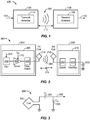
- FIG. 1 is a functional block diagram of a wireless power transfer system 100, in accordance with one example embodiment.
- An input power 102 may be provided to a transmitter 104 from a power source (not shown in this figure) to generate a wireless (e.g., magnetic or electromagnetic) field 105 for performing energy transfer.
- a receiver 108 may couple to the wireless field 105 and generate an output power 110 for storing or consumption by a device (not shown in this figure) coupled to the output power 110. Both the transmitter 104 and the receiver 108 are separated by a distance 112.
- the transmitter 104 and the receiver 108 are configured according to a mutual resonant relationship.
- the resonant frequency of the receiver 108 and the resonant frequency of the transmitter 104 are substantially the same or very close, transmission losses between the transmitter 104 and the receiver 108 are minimal.
- wireless power transfer may be provided over a larger distance in contrast to purely inductive solutions that may require large antenna coils which are very close (e.g., sometimes within millimeters).
- Resonant inductive coupling techniques may thus allow for improved efficiency and power transfer over various distances and with a variety of inductive coil configurations.
- the receiver 108 may receive power when the receiver 108 is located in the wireless field 105 produced by the transmitter 104.
- the wireless field 105 corresponds to a region where energy output by the transmitter 104 may be captured by the receiver 108.
- the wireless field 105 may correspond to the "near-field" of the transmitter 104 as will be further described below.
- the transmitter 104 may include a transmit antenna or coil 114 for transmitting energy to the receiver 108.
- the receiver 108 may include a receive antenna or coil 118 for receiving or capturing energy transmitted from the transmitter 104.
- the near-field may correspond to a region in which there are strong reactive fields resulting from the currents and charges in the transmit coil 114 that minimally radiate power away from the transmit coil 114.
- the near-field may correspond to a region that is within about one wavelength (or a fraction thereof) of the transmit coil 114.
- efficient energy transfer may occur by coupling a large portion of the energy in the wireless field 105 to the receive coil 118 rather than propagating most of the energy in an electromagnetic wave to the far field.
- a "coupling mode" may be developed between the transmit coil 114 and the receive coil 118.
- the area around the transmit antenna 114 and the receive antenna 118 where this coupling may occur is referred to herein as a coupling-mode region.
- FIG. 2 is a functional block diagram of a wireless power transfer system 200, in accordance with another example embodiment.
- the system 200 may be a wireless power transfer system of similar operation and functionality as the system 100 of Fig. 1 . However, the system 200 provides additional details regarding the components of the wireless power transfer system 200 than Fig. 1 .
- the system 200 includes a transmitter 204 and a receiver 208.
- the transmitter 204 may include a transmit circuitry 206 that may include an oscillator 222, a driver circuit 224, and a filter and matching circuit 226.
- the oscillator 222 may be configured to generate a signal at a desired frequency that may be adjusted in response to a frequency control signal 223.
- the oscillator 222 may provide the oscillator signal to the driver circuit 224.
- the driver circuit 224 may be configured to drive the transmit antenna 214 at, for example, a resonant frequency of the transmit antenna 214 based on an input voltage signal (VD) 225.
- the driver circuit 224 may be a switching amplifier configured to receive a square wave from the oscillator 222 and output a sine wave.
- the driver circuit 224 may be a class E amplifier.
- the filter and matching circuit 226 may filter out harmonics or other unwanted frequencies and match the impedance of the transmitter 204 to the transmit antenna 214. As a result of driving the transmit antenna 214, the transmit antenna 214 may generate a wireless field 205 to wirelessly output power at a level sufficient for charging a battery 236 of the electric vehicle 605, for example.
- the receiver 208 may include a receive circuitry 210 that may include a matching circuit 232 and a rectifier circuit 234.
- the matching circuit 232 may match the impedance of the receive circuitry 210 to the receive antenna 218.
- the rectifier circuit 234 may generate a direct current (DC) power output from an alternate current (AC) power input to charge the battery 236, as shown in FIG. 2 .
- the receiver 208 and the transmitter 204 may additionally communicate on a separate communication channel 219 (e.g., Bluetooth, Zigbee, cellular, etc.).
- the receiver 208 and the transmitter 204 may alternatively communicate via in-band signaling using characteristics of the wireless field 205.
- the receiver 208 may be configured to determine whether an amount of power transmitted by the transmitter 204 and received by the receiver 208 is appropriate for charging the battery 236.
- FIG. 3 is a schematic diagram of a portion of the transmit circuitry 206 or the receive circuitry 210 of FIG. 2 , in accordance with some example embodiments.
- a transmit or receive circuitry 350 may include an antenna 352.
- the antenna 352 may also be referred to or be configured as a "loop" antenna 352.
- the antenna 352 may also be referred to herein or be configured as a "magnetic" antenna or an induction coil.
- the term “antenna” generally refers to a component that may wirelessly output or receive energy for coupling to another "antenna.”
- the antenna may also be referred to as a coil of a type that is configured to wirelessly output or receive power.
- the antenna 352 is an example of a "power transfer component" of a type that is configured to wirelessly output and/or receive power.
- the antenna 352 may include an air core or a physical core such as a ferrite core (not shown in this figure). Air core loop antennas may be more tolerable to extraneous physical devices placed in the vicinity of the core. Furthermore, an air core loop antenna 352 allows the placement of other components within the core area. In addition, an air core loop may more readily enable placement of the receive antenna 218 ( FIG. 2 ) within a plane of the transmit antenna 214 ( FIG. 2 ) where the coupled-mode region of the transmit antenna 214 may be more powerful.
- efficient transfer of energy between the transmitter 104 (transmitter 204 as referenced in FIG. 2 ) and the receiver 108 (receiver 208 as referenced in FIG. 2 ) may occur during matched or nearly matched resonance between the transmitter 104 and the receiver 108.
- energy may be transferred, although the efficiency may be affected. For example, the efficiency may be less when resonance is not matched.
- Transfer of energy occurs by coupling energy from the wireless field 105 (wireless field 205 as referenced in FIG. 2 ) of the transmit coil 114 (transmit coil 214 as referenced in FIG. 2 ) to the receive coil 118 (receive coil 218 as referenced in FIG. 2 ), residing in the vicinity of the wireless field 105, rather than propagating the energy from the transmit coil 114 into free space.
- the resonant frequency of the loop or magnetic antennas is based on the inductance and capacitance.
- Inductance may be simply the inductance created by the antenna 352, whereas, capacitance may be added to the antenna's inductance to create a resonant structure at a desired resonant frequency.
- a capacitor 354 and a capacitor 356 may be added to the transmit or receive circuitry 350 to create a resonant circuit that selects a signal 358 at a resonant frequency. Accordingly, for larger diameter antennas, the size of capacitance needed to sustain resonance may decrease as the diameter or inductance of the loop increases.
- the efficient energy transfer area of the near-field may increase.
- Other resonant circuits formed using other components are also possible.
- a capacitor may be placed in parallel between the two terminals of the circuitry 350.
- the signal 358 with a frequency that substantially corresponds to the resonant frequency of the antenna 352, may be an input to the antenna 352.
- the transmitter 104 may output a time varying magnetic (or electromagnetic) field with a frequency corresponding to the resonant frequency of the transmit coil 114.
- the time varying magnetic (or electromagnetic) field may induce a current in the receive coil 118.
- the receive coil 118 is configured to resonate at the frequency of the transmit coil 114, energy may be efficiently transferred.
- the AC signal induced in the receive coil 118 may be rectified as described above to produce a DC signal that may be provided to charge or to power a load.
- the electric vehicle On a roadway with a dynamic wireless charging system comprising a plurality of the base pads placed linearly along a path of travel, the electric vehicle may travel near the plurality of the base pads while traveling on the road. Should the electric vehicle desire to charge its batteries or source energy to power the electric vehicle while traveling, in order to extend its range or reduce the need to charge later, the electric vehicle may request the dynamic wireless charging system activate the base pads along the electric vehicle's path of travel. Such dynamic charging may also serve to reduce or eliminate the need for auxiliary or supplemental motor systems in addition to the electric locomotion system of the electric vehicle (e.g., a secondary gasoline engine of the hybrid/electric vehicle). As such, dynamic wireless charging systems and methods that efficiently and effectively activate the base pads along a path of travel of the electric vehicle are needed.
- auxiliary or supplemental motor systems in addition to the electric locomotion system of the electric vehicle (e.g., a secondary gasoline engine of the hybrid/electric vehicle).
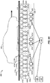
- FIG. 4A illustrates a schematic view of an electric vehicle 405 with at least one vehicle pad 406 in the presence of a wireless power transfer system 400, in accordance with an exemplary embodiment.
- various components of a distribution network of a wireless power transfer system 400 are installed beneath, along or beside a roadway 410.
- the roadway 410 extends from the left side of FIG. 4A to the right side of FIG. 4A , with a direction of travel of the electric vehicle 405 aligned with the roadway 410.
- the electric vehicle 405 may comprise at least one vehicle pad 406, similar to the receivers 108/208, as previously described in connection with FIGs. 1 and 2 , respectively.
- the vehicle pad 406 may comprise a polarized coupling system (e.g., a double-D coil), a quadrature coil system, combined double-D quadrature coil system, or any other system utilizing any other type or shape of coil (e.g., circular, rectangular, or solenoid shapes).
- a vehicle pad 406 (secondary coil) may couple with the magnetic field emitted by the primary coil to receive flux.
- the vehicle pad 406 (secondary coil) may be selected to compliment the primary coil(s) so as to couple with as much of the magnetic field to maximize the received flux.
- a polarized type of vehicle pad 406 may be used in the coupling system (e.g., a double-D coil or a solenoid); alternatively, if the primary coil is producing vertical flux, then a circular coil or a quadrature coil may be used. If the primary coil is producing a combination of horizontal and vertical flux, then a combination vehicle pad 406 may be used, e.g., a DDQ coil.
- the "double-D" may refer to placing two D-shaped coils back to back such that the overall shape of the coil is round.
- a quadrature coil may use four coils as opposed to only two, in various geometries.
- the dynamic wireless charging system 400 may further comprise a plurality of base pads 415a-415r installed in, on, beside, or flush with the roadway 410.
- Each of the base pads 415a-415r may be configured to generate a wireless field (see the wireless field 205 of FIG. 2 ) for wirelessly transferring power to the electric vehicle 405 via the at least one vehicle pad 406 when activated.
- Each of a plurality of switches 420a-420r may be configured to operationally connect a respective one of the base pads 415a-415r to one of a plurality of local controllers 425a-425f via one of a plurality of distribution circuits 421a-421f.
- the local controllers 425a-425f may be configured to wirelessly receive power from a power supply/inverter 435, via an alternating current (AC) power backbone 430, and control an amount of power transferred to one or more of the plurality of base pads 415a-415r via the switches 420a-420r.
- components having multiple iterations e.g., the base pads 415a-415r
- the base pads 415a-415r may be referred to collectively by a single number for simplicity.
- the base pads 415, the switches 420, the distribution circuits 421, and the local controllers 425 may be referred to collectively by a single number for simplicity.
- the power supply/inverter 435 may receive its power from a power source 440.
- the power source 440 and/or the power supply/inverter 435 may be configured to transfer power based on a number of base pads 415 to power, a number of local controllers 425, and/or a number and type of electric vehicles 405 to be charged.
- the power source 440 and the power supply/inverter 435 may provide current at a frequency utilized by the base pads 415 or, alternatively, at some higher or lower frequency.
- the AC power backbone 430 may comprise a loop conductor that distributes the high frequency (HF) power and may be capable of synchronizing the base pads 415 and/or the local controllers 425 that are near each other to a single phase. Thus, the AC power backbone 430 may be considered a phase reference that also distributes power.
- HF high frequency
- the dynamic wireless charging system 400 may further comprise a distribution controller 445.
- the distribution controller 445 may operationally connected to the power supply/inverter 435 and the local controllers 425a-425f.
- the distribution controller 445 may be configured to provide global coordination of power control between the local controllers 425a-425f.
- the base pads 415, the switches 420, and the local controllers 425 may be grouped in a series of individual Base Array Network (BAN) modules 450a-450c.
- BAN modules 450a-450c may comprise six base pads 415 and two local controllers 425, although other arrangements and numbers of base pads and local controllers for BAN modules may be used in other embodiments.
- the respective components of the BAN modules 450 are shaded to indicate respective common current paths.
- the distribution controller 445 may communicate with one or more of the electric vehicle 405, the power supply/inverter 435, and the local controllers 425a-425f to coordinate activation or deactivation of particular ones of the base pads 415a-r.
- the distribution controller 445 may command the power supply/inverter 435 to generate a current and distribute the current to the AC power backbone 430.
- the AC power backbone 430 may utilize the distributed current to wirelessly supply power to the local controllers 425a-425f via a "double couple transformer" (e.g., "double couple units"), the function of which will be described in more detail in connection with FIG. 5 - FIG. 8 below.
- the local controllers 425a-425f may receive the power from the AC power backbone 430 and provide a regulated amount of current to one or more of the base pads 415a-r.
- the local controllers 425 in each BAN module 450 may comprise individual control units capable of independent control from each other.
- the local controllers 425 of each BAN module 450 may comprise a single, shared control unit or processor.
- the base pads 415a-415r may generate wireless fields according to the current received via the respective switch 420a-420r from the local controller 425a-425f and may couple to the at least one vehicle pad 406 to wirelessly transfer power to the electric vehicle 405.
- control of activation of the base pads 415 may be shared to differing degrees between the distribution controller 445 and the local controllers 425a-425f.
- the distribution controller 445 may coordinate the activation and deactivation of the base pads 415a-415r and may coordinate any communications or actions between multiple BAN modules 450a-450c.
- the distribution controller 445 may simply coordinate communications between the BAN modules 450a-450c or the local controllers 425a-425f, while the local controllers 425a-425f may control the base pad activation and sequencing.
- the distribution controller 445 may activate a particular BAN module 450a-450c, but leave timing of the base pad activations to the associate local controller(s) 425a-425f. In yet other embodiments, the distribution controller 445 may communicate only non-critical information to the local controllers 425a-425f and not provide base pad activation information.
- Higher level coordination by the distribution controller 445 combined with the more localized current distribution and regulation at the local controllers 425a-425f may create a more responsive dynamic wireless charging system 400 with decentralized control via the local controllers 425a-425f. This may allow the local controllers 425a-425f to control current flow independently of the distribution controller 445 and allow local control of impedance matching and reactive voltage/amperage (VAr) loading. Such localized control may provide a decreased VAr load compensation response time since instructions need only come from the local controller 425a-425f and not from the distribution controller 445.
- VAr reactive voltage/amperage
- the distribution controller 445 may also obtain information regarding the velocity of the electric vehicle 405 for controlling activation of particular ones of the base pads 415a-415r.
- the distribution controller 445 may obtain this information from the electric vehicle 405 or from various sensors or load analysis of the base pads 415a-415r.
- each of the BAN modules 450a-450c may sense the presence of the electric vehicle 405 and autonomously and selectively activate the appropriate base pads 415a-415r according to a detected presence or location of the electric vehicle 405.
- the BAN modules 450a-450c may receive a signal comprising information regarding the electric vehicle 405 velocity and/or position or an activation command from a neighboring BAN module 450. The received signal may come directly from the neighboring BAN module 450 (e.g., a corresponding local controller 425) or via the distribution controller 445.
- a respective local controller 425 When a respective local controller 425 receives a signal from the distribution controller 445 to activate a specific base pad 415, the respective local controller 425 may activate the switch 420 corresponding to the specific base pad 415. As the vehicle 405 continues in the direction of travel, the local controllers 425a-425f may receive commands from the distribution controller 445 to activate or deactivate specific base pads 415a-415r based on the position of the vehicle pad 406. The local controllers 425a-425f may further control or regulate the current from the AC power backbone 430.
- the base pads 415 from consecutive local controllers 425 may be interleaved or interlaced such that a single local controller 425 may provide power to alternating base pads 415.
- the base pads 415 from a first local controller 425 may be proximally interleaved with the base pads 415 controlled by a second local controller 425 when the two local controllers 425 are within the same BAN module 450.
- alternating base pads 415 are powered by different local controllers 425 and one local controller need not simultaneously power two base pads 415.
- preventing a single local controller 425 from providing current to consecutive base pads 415 may reduce power rating requirements of individual components, as each component need only be capable of handling the current load of a single base pad 415 at a given time.
- a wireless power transfer system having unbalanced reactive power loading may be able to transfer less power than a system having a balanced reactive power loading between the power source (e.g. the AC power backbone 430) and the load, or receiver (e.g., the base pads 415).
- the local controllers 425a-425f may each comprise a tuning circuit or network to tune the current, and consequently the power, available to currently activated base pad(s) 415.
- tuning circuits may allow for maintaining an optimum, or balanced VAr of the wireless charging system 400 within a small range (e.g., +/- 5%) of the designed power tuning value.
- the AC power backbone 430 may vary in length, affecting the overall VAr loading of the system.
- various vehicle tuning topologies may affect the AC power backbone 430 VAr loading in different ways, reflecting different amounts of reactive power load back to the AC power backbone 430 (e.g., based on the vehicle charging system design).
- the tuning circuit or network may be configured to function with only one base pad 415 activated. In another embodiment, the tuning circuit or network may be configured to function with multiple base pads 415 being activated or be applied to one or more of the BAN modules 450a-450c. In another embodiment, the tuning circuit or network may be configured to function with a single base pad 415 or with multiple base pads 415 being activated and receiving a current from a respective local controller 425.
- FIG. 4B illustrates a schematic view of the BAN modules 450 and the components comprising the BAN module 450.
- Fig. 4B depicts the BAN module 450a ( FIG. 4A ) as a modular device comprising the base pads 415a-415f, the plurality of switches 420a-420f, and the plurality of local controllers 425a and 425b (as shown in FIG. 4 ) that may be included in a single enclosure.
- the local controller 425a may be operably connected to distribution circuit 421a, which is connected to switches 420a, 420c, and 420e, which lead to base pads 415a, 415c, and 415e.
- local controller 425b may be connected to distribution circuit 421b, switches 420b, 420d, and 420f, and base pads 415b, 415d, and 415f, in order.
- the respective components of the BAN modules 450 are shaded to indicate the common power distribution paths.
- the base pads 415 are laid out in a manner such that base pads 415 from adjacent local controllers 425 alternate in their layout in the BAN module 450.
- base pads 415a, 415c, and 415e that may be connected to local controller 425a via switches 420a, 420c, and 420e, respectively, may be installed within the BAN module 450 in an interleaved manner with base pads 415b, 415d, and 415f that may be connected to local controller 425b via switches 420b, 420d, and 420f, respectively. Therefore, the pattern of installed base pads 415 in order of electric vehicle 405 travel may be 415a, 415b, 415c, 415d, 415e, and 415f.
- the switches 420a-420f may function to selectively couple the base pads 415a-415f, respectively, to the respective distribution circuit 421.
- the selective coupling may be in response to a signal received from one of local controllers 425a or 425b or from the distribution controller 445.
- the base pad 415 When coupled, the base pad 415 may be capable of receiving a current from the local controller 425 via distribution circuit 421.
- the local controllers 425a-425f (of FIG. 4A ) may control a current flow to the base pads 415a-415r and may control the direction of the current flow through the base pads 415a-415r.
- the switches 420a-420r, the distribution circuit 421, or the base pads 415a-415r themselves may control the direction of the current flow through the base pads 415a-415r.
- the control of the current flow direction through the base pad 415 may provide for minimizing mutual coupling and cross coupling between concurrently activated base pads 415 and adjacent base pads 415.
- the controlling of the current by the distribution circuits 421, local controllers 425 or the switches 420 discussed above may comprise at least one of controlling the magnitude of the current or the phase of the current being sent to the base pads 415.
- Such controlling by the distribution circuits 421, the local controllers 425, or the switches 420 may provide for the manipulation of the wireless fields generated by the base pads 415.
- the phase of the current flow through the connected base pad 415 may be limited to one of zero or 180 degrees. In some other embodiments, the phase of the current flow may be any value between zero and 360 degrees.
- the BAN module 450 may operate as a sub-tree network of the dynamic wireless charging system 400.
- the BAN module 450 may function as a self-contained unit where its internal components may be coordinated and preassembled and connected such that the BAN module 450 is designed to distribute and control the current distribution over a limited distance. As depicted, internally there are two local controllers, 425a and 425b, two distribution circuits 421a and 421b, switches 420a-420f, and base pads 415a-415f.
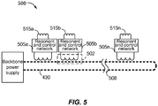
- FIG. 5 depicts a block diagram of a wireless power transfer system according to the disclosure.
- FIG. 5 shows a wireless power transfer system 500, comprising the backbone 430 (of FIG. 4A and FIG. 4B ) and a series of resonant and control networks ("network") 505a-505n.
- the system 500 operates similarly to the system 400.
- Three networks 505 are shown, however a break 508 depicted in the backbone 430 indicates that any number of networks 505 may be implemented, in the same way a series of the BAN modules 450 may be utilized in the system 400.
- Each network 505 may function similarly to the local controllers 425, distribution circuits 421, and switches 420 as described above with respect to the BAN modules 450.
- the networks 505 may complete the switching functions of the switches 420 and providing current for the proper functioning of the base pads 515, shown as base pad 515a to base pad 515n corresponding to the networks 505.
- the base pads 515 may be substantially similar to the base pads 415, described above however the base pads 515 shown here may be representative of multiple base pads 415, in accordance with previous FIG. 4A and FIG. 4B .
- a number of double couple transformers 502 transfer power from the backbone 430 to each of the base pads 415.
- "Double couple,” as used to herein, generally relates to the notion that there are two wireless couplings associated with each double couple transformer: a first coupling between the backbone 430 and the double couple transformer and a second coupling between the vehicle pad 415 and the vehicle pad 406, hence "double couple.”
- the backbone 430 provides inductive power to a first coil or coils of the double couple transformer 502, which then provides current via the network of local controllers 425, distribution circuits 421, and switches 420, to one or more base pads 415 that is in turn coupled to the vehicle pad 406.
- each double couple transformer 502 may comprise at least one coil (e.g., a transformer) configured to wirelessly couple with the backbone 430 and receive wireless power. The double couple transformer 502 may then supply current and power via the network 505 to the base pad(s) 515.
- the BAN modules 450 may comprise six base pads 415 each.
- the double couple transformers 502 shown in FIG. 5 are depicted as operationally coupled to a single base pad 515 for simplicity, however each BAN module 450 may further comprise two or more double couple transformers, for example, providing power to each of three of the base pads 415.
- Each double couple transformer 502 may comprise a series of windings around a core comprising ferromagnetic materials (shown below in connection with FIG.
- the core may comprise a ferrite or other ferromagnetic material.
- the double couple transformers 502 may operate similar to a transformer, receiving wireless power from the backbone 430 via a wireless field (not shown) similar to the wireless field 105. The wireless power received at the double couple transformer 502 may then be transferred through the network 505 and ultimately to the base pads 515.
- FIG. 6A depicts one example of a balance control switching system 600.
- the system 600 may operate similar to the local controllers 425, switches 421, and the base pads 415.
- the system 600 may comprise a core 610 in proximity to the backbone 430.
- the core 610 may comprise a ferrite core or other suitable ferromagnetic material.
- the core 610 may have at least one series of windings comprising a coil 612 around the core 610 configured to wirelessly couple with a wireless field 605 produced by the backbone 430.
- the wireless field 605 may be a magnetic (electromagnetic) field similar to the wireless field 105 ( FIG. 1 ) and the wireless field 205 ( FIG. 3 ).
- FIG. 1 the wireless field 205
- the core 610 is shown partially surrounding the backbone 430, however this should not be considered limiting.
- the core 610 may be disposed in other configurations allowing wireless coupling that do not surround the backbone 430, such as configurations where the core 610 is next to or alongside the backbone 430.
- the system 600 may be incorporated into the BAN module 450 providing circuitry and logic to transfer wireless power from the backbone 430 to the base pads 415.
- the system 600 may further comprise a resonant and control network (network) 602 operationally coupled to the coil 612 and configured to selectively provide current to at least one base pad 615.
- the coil 612 may comprise a power coil for the double couple transformer 602, similar to the double couple transformer 502 of FIG. 5 .
- the double couple transformer 602 may produce current for use by the resonant and control network 604 which may in turn selectively supply current to a series of base pads 615.
- the base pads 615 may operate similarly to the base pads 415 and the base pads 515, receiving current from the network 604 and providing wireless power to a wireless power receiver, such as the vehicle 405.
- the network 604 may operate similarly to the networks 505 and provide the functionality of the switches 420, distribution circuits 421, and the local controllers 425 of FIG. 4 .
- the presence of the ferrite core 610 in proximity of the backbone 430 may increase the overall inductance (impedance) and affect the VAr loading as measured at the backbone 430 and/or the power supply/inverter 435.
- the core 610 represents an inductive load to the backbone 430.
- additional inductors or capacitors may be included within the system 600 to compensate for variations in VAr loading. In some embodiments, this may be termed a compensation circuit. Inductors and capacitors may be used in series or in parallel with the inductive load to increase or decrease the VAr loading as measured at the power supply/inverter 435.
- an active compensation circuit may commonly require the addition of separate electronic components, increasing the cost and complexity of the system. The system 600 however may not require such additional components in an active compensation circuit for VAr load compensation.
- the system 600 may further comprise a plurality of control switches 620, shown here as a control switch 620a and a control switch 620b.
- the control switches 620 may operationally connect the coil 612 of the double couple transformer 602 to the network 604.
- the positions of each of the switches 620 may serve to adjust the impedance of the system 600 on the backbone 430 compensating for VAr loading.
- three primary switch states may be considered.
- a first, powered state the switch 620a is closed and the switch 620b is open.
- This powered switch state completes the circuit for the current induced in the double couple transformer 602 allowing the current to flow and convey or provide power to the network 604, and in turn to the base pad 615.
- the switch 620a and the switch 620b are both open.
- This open circuit state opens the circuit, removing power from the circuit and eliminating current flow to the network 604 and the base pad 615.
- the system 600 remains an inductive load (e.g., an impedance) on the backbone 430, increasing the VAr load.
- switch 620b is closed, short circuiting the coil 612 around the core 610.
- the short circuit switch state then nearly eliminates the system 600 as an inductive load on the backbone 430, reducing the impedance to a negligible value.
- the presence of the core 610 becomes nearly invisible to the backbone 430.
- the incorporation of the control switches 620 providing the three states (powered, open, short) may serve as an inductive load compensation system using existing components (e.g., the system 600) without the addition of additional circuitry as noted above.
- the inactive double couple transformers 502, 602 within a BAN module 450 may therefore be used to tune the overall VAr loading of the system 400.
- FIG. 6B depicts a balance control switching system 650 having a ramp control switch according to the disclosure.
- the system 650 may operate within the BAN module 450, providing switching control between the backbone 430 and the base pads 415.
- the balance control switching system 650 may be substantially similar to the balance control switching system 600 however, the system 650 comprises an additional power flow ramp controller (ramp controller) 660.
- the ramp controller 660 comprises a control coil 662 having windings surround the core 610.
- the ramp controller 660 may further comprise a control switch 664 operably connected to the coil 662.
- the ramp controller 660 may be adjacent to the double couple transformer 602, however the coil 612 and the coil 662 may be electrically isolated. Similar to the coil 612, the coil 662 may be situated within wireless field 605, thus the coil 662 may simultaneously wirelessly couple to the backbone 430 with the coil 612.
- the double couple transformer 602 of the system 600 may support high voltages (e.g., 1kV - 4kV) as noted above with respect to FIG. 4A .
- the resonant and control network 604 may be exposed to very high transient voltages when the coil 612 is shorted using only the switch 620b.
- the very high transient voltages may negatively affect the connected electronic components (e.g., of the resonant and control network 604, the switches 620, etc.) and in some embodiments may lead to component failure.
- the switch 664 may be closed, shorting the coil 662 around the core 610 providing a shunt to the current induced in the coil 612.
- the shorted coil 662 (and shunt) may reduce the amount of current induced (by the backbone 430) within the coil 612, allowing the resonant and control network 604 to short the switch 620b without the associated high transient voltages.
- FIG. 6C illustrates a schematic diagram 670 depicting the electrical relationship between the components of FIG. 6B .
- the backbone 430 is depicted on the left of FIG. 6C , having an inductance "L b ,” coupled to a double couple transformer 672.
- the double couple transformer 672 may be similar to the double couple transformers 502, 602 described above.
- the double couple transformer 672 is represented by the inductive load “L k " (e.g., an inductive load) and a tuning capacitor "C k .”
- the tuning capacitor "C k .” may be implemented for load compensation at the double couple transformer 672.
- the base pad 415 ( FIG. 4 ) may be represented by an inductive load "L 1 " and an associated tuning capacitor or capacitive load “C 1 .”
- the L 1 may represent at least one base pad 415. In at least one embodiment, the L 1 may represent three or more base pads 415.
- FIG. 6C further depicts the ramp controller 660 ( FIG. 6B ) also coupled to the backbone 430.
- an inductive load “L ctrl” may be representative of the control coil 662 (of FIG. 6B ).
- the control coil L ctrl may be operably coupled in parallel with a diode 676, and further operable coupled in series to a load comprising an inductive load “L dc " and a capacitive load, "C dc .”
- a control switch 674 similar to the switch 662 ( FIG. 6B ) may be placed across the two inductive loads L ctrl and L dc , in order to achieve the shunt current discussed in connection with FIG. 6B . Accordingly, when the switch 674 is closed, the induced current in the inductive load L k is reduced to a manageable level.
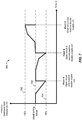
- FIG. 7 depicts a chart 700 showing variations in reactive power (VAr) loading according to the disclosure and in conjunction with the embodiments described above.
- the X axis of the chart 700 describes time (t) and the Y axis of the chart 700 depicts effective backbone 430 track inductance (henry (H)) as measured at the power supply/inverter 435.
- An ideal tuning line 702 is depicted between a negative value line 704 and a positive value line 706.
- ideal VAr loading may vary between minus five percent (-5%) of the ideal tuning line 702. The minus five percent is indicated by the negative value line 704 and the plus five percent (+5%) as indicated by the positive value line 706.
- the ideal tuning line 702 may further represent a balanced VAr load or reactance.
- Such a balance may be generally considered the conditions under which the reactive power produced by the backbone 430 ( FIG. 4A ) equals the reactive power consumed by the load on the backbone 430.
- the load on the backbone 430 may comprise the series of BAN modules 450 as shown in FIG. 4A and the vehicle 405.
- the load may further comprise certain aspects of the systems 400, 500, 600, 650 described in connection with FIG. 4B through FIG. 6C . It is to be appreciated that +/- 5 percent may be adjusted based on system architecture and other power-related factors and is provided only as an example.
- the resonance and control network 604 may open the switches 620 on an inactive double couple transformer 602, increasing the effective inductive load as measured at the power supply/inverter 435.
- the resonance and control network 604 may open the switches 620 (open circuit) on a second inactive double couple transformer 602, further increasing the inductive load.
- the resonance and control network 604 may short circuit an inactive double couple transformer 602 which may reduce the effective inductive load of that double couple transformer 602 at the backbone 430 to a nearly negligible value. Accordingly, the resonance and control networks 604, as commanded by a respective local controller 425 ( FIG. 4 ) may be used to compensate for variations in VAr loading by open circuiting or short circuiting one of the plurality of double couple transformers 602 within the BAN module 450 array that comprised the system 400 ( FIG. 4A ).
- FIG. 8 is a flowchart depicting a method according to the disclosure.
- FIG. 8 shows a method 800 describing a method for reactive power (VAr) compensation in a dynamic wireless charging system using inactive electronic components.
- the method 800 describes the use of one or more inactive double couple transformers 602 within the exemplary system 400 to increase or decrease the inductive load as measured at the power supply/inverter 435 in order to maintain maximum power transfer between the backbone 430 and the base pads 415 ( FIG. 4A ).
- the effective inductance as measured at the power supply/inverter 435 may compensated or otherwise adjusted to a desired level in discrete steps.
- the method 800 begins with block 805 wherein the local controller 425 ( FIG. 4 ) may receive instructions from the distribution controller 415 ( FIG. 4A ).
- the instructions may comprise indicating a presence of an electric vehicle 405 ( FIG. 4A ) in proximity to one or more base pads 415 ( FIG. 4A ).
- the instructions may further comprise a command to activate one or more of the connected double couple transformers 602 and/or the base pads 415.
- the distribution controller may provide instructions to one or more local controllers to activate one or more base pads 415 in order to provide wireless power to the electric vehicle 405.
- the instructions may further indicate a specific sequence in which the base pads 415 are to be activated and deactivated.
- the local controller 425 may determine a total number of active and inactive double couple transformers 602 during wireless charging operations of the system 400.
- the determining may comprise monitoring the number of active and inactive base pads 415 connected to the local controller 425.
- the determining may comprise monitoring the number of active and double couple transformers 602 connected to the local controller 425.
- the determining may further comprise receiving an indication from an adjacent local controlled 425 or BAN module 450 indicating the total number of active and inactive base pads 415 or the total number of active and inactive double couple transformers 602 active in the entire system 400.
- the local controller may determine a reactive power loading of a power supply.
- the determining may comprise determining in a single BAN module 450, of which the local controller 425 is a part, the value of the reactive power loading.
- the determination at block 815 may further comprise receiving an indication from an adjacent BAN module 450 of the reactive power loading in the adjacent BAN module 450.
- the BAN module 450b FIG. 4A
- the determination at block 815 may further comprise an indication from the distribution controller 445 of the reactive power loading at the power supply/inverter 435.
- the local controller 425 may further selectively activate the control switches 420, 620 in response to the reactive power loading.
- the local controller 425 may activate the control switches 620 to open the circuit (e.g., the open circuit state of FIG. 6A ) and remove current from the resonant and control network 604.
- the local controller 425 may activate the control switches 620 to short circuit (e.g., the third, short circuit state of FIG. 6A ) to short the coil 612 ( FIG. 6A, FIG. 6B ) around the core 610.
- the open, short, and powered states of the control switches 620 may be selectively activated in response to the reactive power load of the power supply/inverter 435.
- the local controller 425 may autonomously select the switch 620 states in response to indications from the distribution controller 445 and the determination of the number of active and inactive double couple transformers in block 810.
- the local controller 425 may transmit a message indicating the number of active and inactive double couple transformers 602.
- the message may further indicate a switch 620 position.
- the message may be transmitted as a feedback signal to the distribution controller 445.
- the message may be transmitted to an adjacent BAN module 450 or to one of the local controllers 425 therein. These messages may provide a feedback signal or an advanced warning to adjacent local controllers 425 to expect a change in the reactive power loading. Such a message may increase the effectiveness of reactive power load compensation.
- any suitable means capable of performing the operations such as various hardware and/or software component(s), circuits, and/or module(s).
- any operations illustrated in the Figures may be performed by corresponding functional means capable of performing the operations.
- Information and signals may be represented using any of a variety of different technologies and techniques.
- data, instructions, commands, information, signals, bits, symbols, and chips that may be referenced throughout the above description may be represented by voltages, currents, electromagnetic waves, magnetic fields or particles, optical fields or particles, or any combination thereof.
- DSP Digital Signal Processor
- ASIC Application Specific Integrated Circuit
- FPGA Field Programmable Gate Array
- a general purpose processor may be a microprocessor, but in the alternative, the processor may be any conventional processor, controller, microcontroller, or state machine.
- a processor may also be implemented as a combination of computing devices, e.g., a combination of a DSP and a microprocessor, a plurality of microprocessors, one or more microprocessors in conjunction with a DSP core, or any other such configuration.
- a software module may reside in Random Access Memory (RAM), flash memory, Read Only Memory (ROM), Electrically Programmable ROM (EPROM), Electrically Erasable Programmable ROM (EEPROM), registers, hard disk, a removable disk, a CD ROM, or any other form of storage medium known in the art.
- RAM Random Access Memory
- ROM Read Only Memory
- EPROM Electrically Programmable ROM
- EEPROM Electrically Erasable Programmable ROM
- registers hard disk, a removable disk, a CD ROM, or any other form of storage medium known in the art.
- a storage medium is coupled to the processor such that the processor can read information from, and write information to, the storage medium.
- the storage medium may be integral to the processor.
- Disk and disc includes compact disc (CD), laser disc, optical disc, digital versatile disc (DVD), floppy disk and Blu-ray disc where disks usually reproduce data magnetically, while discs reproduce data optically with lasers. Combinations of the above should also be included within the scope of computer readable media.
- the processor and the storage medium may reside in an ASIC.
- the ASIC may reside in a user terminal.
- the processor and the storage medium may reside as discrete components in a user terminal.
Landscapes
- Engineering & Computer Science (AREA)
- Power Engineering (AREA)
- Transportation (AREA)
- Mechanical Engineering (AREA)
- Computer Networks & Wireless Communication (AREA)
- Life Sciences & Earth Sciences (AREA)
- Sustainable Development (AREA)
- Sustainable Energy (AREA)
- Charge And Discharge Circuits For Batteries Or The Like (AREA)
- Electric Propulsion And Braking For Vehicles (AREA)
- Current-Collector Devices For Electrically Propelled Vehicles (AREA)
Description
- This application is generally related to wireless power charging of chargeable devices such as electric vehicles.
- Chargeable systems, such as vehicles, have been introduced that include locomotion power derived from electricity received from an energy storage device such as a battery. For example, hybrid electric vehicles include on-board chargers that use power from vehicle braking and traditional motors to charge the vehicles. Vehicles that are solely electric generally receive the electricity for charging the batteries from other sources. Battery electric vehicles are often proposed to be charged through some type of wired alternating current (AC) such as household or commercial AC supply sources. The wired charging connections require cables or other similar connectors that are physically connected to a power supply. Cables and similar connectors may sometimes be inconvenient or cumbersome and have other drawbacks. It is desirable to provide wireless charging systems that are capable of transferring power in free space (e.g., via a wireless field) to be used to charge the electric vehicle to overcome some of the deficiencies of wired charging solutions.
-
WO 2014/007656 discloses such free space wireless charging systems for vehicles. - Embodiment of wireless charging systems may require the use of ferromagnetic materials. The presence of such materials may influence the overall reactive power balance of a system. Accordingly, wireless charging system should be capable of balancing overall reactive power using existing system components to properly coordinate the transfer of power continuously to a moving receiver.
- One aspect of the disclosure provides a device for dynamically tuning reactive power in an inductive power transfer system comprising a first plurality of coils. Each coil of the plurality of coils is operably coupled to a respective ferromagnetic material. Each coil of the plurality of coils is configured to receive wireless power via the ferromagnetic material from a power source. The device further comprises a plurality of switches associated with each of the first plurality of coils. The switches are configured to selectively control power received by certain of the first plurality of coils. The device further comprises a second plurality of coils configured to receive current from respective ones of the first plurality of coils. The second plurality of coils is further configured to deliver wireless power to a wireless power receiver. The device further comprises at least one control unit configured to selectively activate the switches. The switches may be configurably set to convey power from the power source to at least one of the plurality of the second coils or selectively increase or decrease the reactive power load of the power source.
- Another aspect of the disclosure provides a method for dynamically tuning reactive power in an inductive power transfer system. The method comprises receiving at a first plurality of coils, wireless power via a ferromagnetic material from a power source. Each coil of the first plurality of coils is operably coupled to the respective ferromagnetic material. The method further comprises selectively controlling, at a plurality of switches, power received by certain of the first plurality of coils. Each switch of the plurality of switches is associated with each coil of the first plurality of coils. The method further comprises receiving, at a second plurality of coils, current from respective ones of the first plurality of coils. The method further comprises delivering, by the second plurality of coils, wireless power to a wireless power receiver. The method further comprises selectively activating the switches by at least one control unit. The switches are configurably set to provide convey from the power source to at least one of the plurality of the second coils or selectively increase or decrease the reactive power load of the power source.
- Another aspect of the disclosure provides an apparatus for dynamically tuning reactive power in an inductive power transfer system. The apparatus comprises first means for receiving wireless power via a ferromagnetic material from a power source. The first receiving means is operably coupled to the respective ferromagnetic material. The apparatus further comprises means for selectively controlling power received by certain of the first receiving means. The controlling means is associated with each of the first receiving means. The apparatus further comprises second means for receiving current from respective ones of the first receiving means. The apparatus further comprises means for delivering wireless power to a wireless power receiver. The apparatus further comprises means for selectively activating the controlling means. The controlling means configurably set to convey power from the power source to at least one of the plurality of the second receiving means or selectively increase or decrease the reactive power load of the power source.
- Another aspect of the disclosure provides a non-transitory computer-readable medium. The medium comprise instructions, that when executed, cause a inductive power transfer system to receive at a first plurality of coils, wireless power via a ferromagnetic material from a power source, wherein each coil of the first plurality of coils is operably coupled to the respective ferromagnetic material. The medium further causes the inductive power transfer system to selectively control, at a plurality of switches, power received by certain of the first plurality of coils. Each switch of the plurality of switches is associated with each coil of the first plurality of coils. The medium further causes the inductive power transfer system to receive, at a second plurality of coils, current from respective ones of the first plurality of coils. The medium further causes the inductive power transfer system to deliver, by the second plurality of coils, wireless power to a wireless power receiver. The medium further causes the inductive power transfer system to selectively activate the switches by at least one control unit, wherein the switches are configurably set to convey power from the power source to a portion of the plurality of the second coils or selectively increase or decrease the reactive power load of the power source.
- The above-mentioned aspects, as well as other features, aspects, and advantages of the present technology will now be described in connection with various embodiments, with reference to the accompanying drawings. The illustrated embodiments, however, are merely examples and are not intended to be limiting. Throughout the drawings, similar symbols typically identify similar components, unless context dictates otherwise. Note that the relative dimensions of the following figures may not be drawn to scale.
-
FIG. 1 is a functional block diagram of a wireless power transfer system, in accordance with one example of an embodiment. -
FIG. 2 is a functional block diagram of a wireless power transfer system, in accordance with another example embodiment. -
FIG. 3 is a schematic diagram of a portion of transmit circuitry or receive circuitry ofFIG. 2 including a transmit or receive antenna, in accordance with some example embodiments. -
FIG. 4A illustrates a schematic view of an electric vehicle with at least one vehicle pad in the presence of a dynamic wireless electric vehicle charging system in accordance with an embodiment. -
FIG. 4B illustrates a schematic view of a base array network module, in accordance with an embodiment. -
FIG. 5 depicts a block diagram of a wireless power transfer system in accordance with an embodiment. -
FIG. 6A depicts an embodiment of a balance control switching system according to the disclosure. -
FIG. 6B depicts an embodiment of a balance control switching system with a ramp control switch according to the disclosure. -
FIG. 6C illustrates a schematic diagram depicting the electrical relationship between the components ofFIG. 6B . -
FIG. 7 depicts a chart showing variations in reactive power (VAr) loading according to the disclosure. -
FIG. 8 is a flowchart depicting a method according to the disclosure. - In the following detailed description, reference is made to the accompanying drawings, which form a part of the present disclosure.
- Wireless power transfer may refer to transferring any form of energy associated with electric fields, magnetic fields, electromagnetic fields, or otherwise from a transmitter to a receiver without the use of physical electrical conductors (e.g., power may be transferred through free space). The power output into a wireless field (e.g., a magnetic field or an electromagnetic field) may be received, captured by, or coupled by a "receive antenna" to achieve power transfer.
- An electric vehicle is used herein to describe a remote system, an example of which is a vehicle that includes, as part of its motion capabilities, electrical power derived from a chargeable energy storage device (e.g., one or more rechargeable electrochemical cells or other type of battery). As non-limiting examples, some electric vehicle may be hybrid electric vehicles that include besides electric motors, a traditional combustion engine for direct locomotion or to charge the vehicle's battery. Other electric vehicles may draw all locomotion ability from electrical power. The electric vehicle is not limited to an automobile and may include motorcycles, carts, scooters, and the like. By way of example and not limitation, a remote system is described herein in the form of the electric vehicle (EV). Furthermore, other remote systems that may be at least partially powered using a chargeable energy storage device are also contemplated (e.g., electronic devices such as personal computing devices and the like).
- The terminology used herein is for the purpose of describing particular embodiments only and is not intended to be limiting of the disclosure. It will be understood that if a specific number of a claim element is intended, such intent will be explicitly recited in the claim, and in the absence of such recitation, no such intent is present. For example, as used herein, the singular forms "a", "an" and "the" are intended to include the plural forms as well, unless the context clearly indicates otherwise. As used herein, the term "and/or" includes any and all combinations of one or more of the associated listed items. It will be further understood that the terms "comprises," "comprising," "includes," and "including," when used in this specification, specify the presence of stated features, integers, steps, operations, elements, and/or components, but do not preclude the presence or addition of one or more other features, integers, steps, operations, elements, components, and/or groups thereof. Expressions such as "at least one of," when preceding a list of elements, modify the entire list of elements and do not modify the individual elements of the list.
-
FIG. 1 is a functional block diagram of a wirelesspower transfer system 100, in accordance with one example embodiment. Aninput power 102 may be provided to atransmitter 104 from a power source (not shown in this figure) to generate a wireless (e.g., magnetic or electromagnetic)field 105 for performing energy transfer. Areceiver 108 may couple to thewireless field 105 and generate anoutput power 110 for storing or consumption by a device (not shown in this figure) coupled to theoutput power 110. Both thetransmitter 104 and thereceiver 108 are separated by adistance 112. - In one example embodiment, the
transmitter 104 and thereceiver 108 are configured according to a mutual resonant relationship. When the resonant frequency of thereceiver 108 and the resonant frequency of thetransmitter 104 are substantially the same or very close, transmission losses between thetransmitter 104 and thereceiver 108 are minimal. As such, wireless power transfer may be provided over a larger distance in contrast to purely inductive solutions that may require large antenna coils which are very close (e.g., sometimes within millimeters). Resonant inductive coupling techniques may thus allow for improved efficiency and power transfer over various distances and with a variety of inductive coil configurations. - The
receiver 108 may receive power when thereceiver 108 is located in thewireless field 105 produced by thetransmitter 104. Thewireless field 105 corresponds to a region where energy output by thetransmitter 104 may be captured by thereceiver 108. Thewireless field 105 may correspond to the "near-field" of thetransmitter 104 as will be further described below. Thetransmitter 104 may include a transmit antenna orcoil 114 for transmitting energy to thereceiver 108. Thereceiver 108 may include a receive antenna orcoil 118 for receiving or capturing energy transmitted from thetransmitter 104. The near-field may correspond to a region in which there are strong reactive fields resulting from the currents and charges in the transmitcoil 114 that minimally radiate power away from the transmitcoil 114. The near-field may correspond to a region that is within about one wavelength (or a fraction thereof) of the transmitcoil 114. - As described above, efficient energy transfer may occur by coupling a large portion of the energy in the
wireless field 105 to the receivecoil 118 rather than propagating most of the energy in an electromagnetic wave to the far field. When positioned within thewireless field 105, a "coupling mode" may be developed between the transmitcoil 114 and the receivecoil 118. The area around the transmitantenna 114 and the receiveantenna 118 where this coupling may occur is referred to herein as a coupling-mode region. -
FIG. 2 is a functional block diagram of a wirelesspower transfer system 200, in accordance with another example embodiment. Thesystem 200 may be a wireless power transfer system of similar operation and functionality as thesystem 100 ofFig. 1 . However, thesystem 200 provides additional details regarding the components of the wirelesspower transfer system 200 thanFig. 1 . Thesystem 200 includes atransmitter 204 and areceiver 208. Thetransmitter 204 may include a transmitcircuitry 206 that may include anoscillator 222, adriver circuit 224, and a filter and matchingcircuit 226. Theoscillator 222 may be configured to generate a signal at a desired frequency that may be adjusted in response to afrequency control signal 223. Theoscillator 222 may provide the oscillator signal to thedriver circuit 224. Thedriver circuit 224 may be configured to drive the transmitantenna 214 at, for example, a resonant frequency of the transmitantenna 214 based on an input voltage signal (VD) 225. Thedriver circuit 224 may be a switching amplifier configured to receive a square wave from theoscillator 222 and output a sine wave. For example, thedriver circuit 224 may be a class E amplifier. - The filter and matching
circuit 226 may filter out harmonics or other unwanted frequencies and match the impedance of thetransmitter 204 to the transmitantenna 214. As a result of driving the transmitantenna 214, the transmitantenna 214 may generate awireless field 205 to wirelessly output power at a level sufficient for charging abattery 236 of theelectric vehicle 605, for example. - The
receiver 208 may include a receivecircuitry 210 that may include amatching circuit 232 and arectifier circuit 234. Thematching circuit 232 may match the impedance of the receivecircuitry 210 to the receiveantenna 218. Therectifier circuit 234 may generate a direct current (DC) power output from an alternate current (AC) power input to charge thebattery 236, as shown inFIG. 2 . Thereceiver 208 and thetransmitter 204 may additionally communicate on a separate communication channel 219 (e.g., Bluetooth, Zigbee, cellular, etc.). Thereceiver 208 and thetransmitter 204 may alternatively communicate via in-band signaling using characteristics of thewireless field 205. - The
receiver 208 may be configured to determine whether an amount of power transmitted by thetransmitter 204 and received by thereceiver 208 is appropriate for charging thebattery 236. -
FIG. 3 is a schematic diagram of a portion of the transmitcircuitry 206 or the receivecircuitry 210 ofFIG. 2 , in accordance with some example embodiments. As illustrated inFIG. 3 , a transmit or receivecircuitry 350 may include anantenna 352. Theantenna 352 may also be referred to or be configured as a "loop"antenna 352. Theantenna 352 may also be referred to herein or be configured as a "magnetic" antenna or an induction coil. The term "antenna" generally refers to a component that may wirelessly output or receive energy for coupling to another "antenna." The antenna may also be referred to as a coil of a type that is configured to wirelessly output or receive power. As used herein, theantenna 352 is an example of a "power transfer component" of a type that is configured to wirelessly output and/or receive power. - The
antenna 352 may include an air core or a physical core such as a ferrite core (not shown in this figure). Air core loop antennas may be more tolerable to extraneous physical devices placed in the vicinity of the core. Furthermore, an aircore loop antenna 352 allows the placement of other components within the core area. In addition, an air core loop may more readily enable placement of the receive antenna 218 (FIG. 2 ) within a plane of the transmit antenna 214 (FIG. 2 ) where the coupled-mode region of the transmitantenna 214 may be more powerful. - As stated, efficient transfer of energy between the transmitter 104 (
transmitter 204 as referenced inFIG. 2 ) and the receiver 108 (receiver 208 as referenced inFIG. 2 ) may occur during matched or nearly matched resonance between thetransmitter 104 and thereceiver 108. However, even when resonance between thetransmitter 104 andreceiver 108 are not matched, energy may be transferred, although the efficiency may be affected. For example, the efficiency may be less when resonance is not matched. Transfer of energy occurs by coupling energy from the wireless field 105 (wireless field 205 as referenced inFIG. 2 ) of the transmit coil 114 (transmitcoil 214 as referenced inFIG. 2 ) to the receive coil 118 (receivecoil 218 as referenced inFIG. 2 ), residing in the vicinity of thewireless field 105, rather than propagating the energy from the transmitcoil 114 into free space. - The resonant frequency of the loop or magnetic antennas is based on the inductance and capacitance. Inductance may be simply the inductance created by the
antenna 352, whereas, capacitance may be added to the antenna's inductance to create a resonant structure at a desired resonant frequency. As a non-limiting example, acapacitor 354 and acapacitor 356 may be added to the transmit or receivecircuitry 350 to create a resonant circuit that selects asignal 358 at a resonant frequency. Accordingly, for larger diameter antennas, the size of capacitance needed to sustain resonance may decrease as the diameter or inductance of the loop increases. - Furthermore, as the diameter of the antenna increases, the efficient energy transfer area of the near-field may increase. Other resonant circuits formed using other components are also possible. As another non-limiting example, a capacitor may be placed in parallel between the two terminals of the
circuitry 350. For transmit antennas, thesignal 358, with a frequency that substantially corresponds to the resonant frequency of theantenna 352, may be an input to theantenna 352. - In
FIG. 1 , thetransmitter 104 may output a time varying magnetic (or electromagnetic) field with a frequency corresponding to the resonant frequency of the transmitcoil 114. When thereceiver 108 is within thewireless field 105, the time varying magnetic (or electromagnetic) field may induce a current in the receivecoil 118. As described above, if the receivecoil 118 is configured to resonate at the frequency of the transmitcoil 114, energy may be efficiently transferred. The AC signal induced in the receivecoil 118 may be rectified as described above to produce a DC signal that may be provided to charge or to power a load. - Many current wireless vehicle charging systems require the electric vehicle being charged to be stationary, i.e., stopped near or above the wireless charging system such that the electric vehicle maintains presence within the wireless field generated by the wireless charging system for transferring charge. Thus, while the electric vehicle is being charged by such a wireless charging system, the electric vehicle may not be used for transportation. Dynamic wireless charging systems that are capable of transferring power across free space may overcome some of the deficiencies of stationary wireless charging stations.
- On a roadway with a dynamic wireless charging system comprising a plurality of the base pads placed linearly along a path of travel, the electric vehicle may travel near the plurality of the base pads while traveling on the road. Should the electric vehicle desire to charge its batteries or source energy to power the electric vehicle while traveling, in order to extend its range or reduce the need to charge later, the electric vehicle may request the dynamic wireless charging system activate the base pads along the electric vehicle's path of travel. Such dynamic charging may also serve to reduce or eliminate the need for auxiliary or supplemental motor systems in addition to the electric locomotion system of the electric vehicle (e.g., a secondary gasoline engine of the hybrid/electric vehicle). As such, dynamic wireless charging systems and methods that efficiently and effectively activate the base pads along a path of travel of the electric vehicle are needed.
-
FIG. 4A illustrates a schematic view of anelectric vehicle 405 with at least onevehicle pad 406 in the presence of a wireless power transfer system 400, in accordance with an exemplary embodiment. As shown inFIG. 4A , various components of a distribution network of a wireless power transfer system 400 are installed beneath, along or beside aroadway 410. Theroadway 410 extends from the left side ofFIG. 4A to the right side ofFIG. 4A , with a direction of travel of theelectric vehicle 405 aligned with theroadway 410. Theelectric vehicle 405 may comprise at least onevehicle pad 406, similar to thereceivers 108/208, as previously described in connection withFIGs. 1 and 2 , respectively. - In some embodiments, the
vehicle pad 406 may comprise a polarized coupling system (e.g., a double-D coil), a quadrature coil system, combined double-D quadrature coil system, or any other system utilizing any other type or shape of coil (e.g., circular, rectangular, or solenoid shapes). A vehicle pad 406 (secondary coil) may couple with the magnetic field emitted by the primary coil to receive flux. In some embodiments, the vehicle pad 406 (secondary coil) may be selected to compliment the primary coil(s) so as to couple with as much of the magnetic field to maximize the received flux. If the primary coil is producing polarized (i.e., horizontal) flux, then a polarized type ofvehicle pad 406 may be used in the coupling system (e.g., a double-D coil or a solenoid); alternatively, if the primary coil is producing vertical flux, then a circular coil or a quadrature coil may be used. If the primary coil is producing a combination of horizontal and vertical flux, then acombination vehicle pad 406 may be used, e.g., a DDQ coil. The "double-D" may refer to placing two D-shaped coils back to back such that the overall shape of the coil is round. A quadrature coil may use four coils as opposed to only two, in various geometries. The dynamic wireless charging system 400 may further comprise a plurality ofbase pads 415a-415r installed in, on, beside, or flush with theroadway 410. Each of thebase pads 415a-415r may be configured to generate a wireless field (see thewireless field 205 ofFIG. 2 ) for wirelessly transferring power to theelectric vehicle 405 via the at least onevehicle pad 406 when activated. Each of a plurality ofswitches 420a-420r may be configured to operationally connect a respective one of thebase pads 415a-415r to one of a plurality oflocal controllers 425a-425f via one of a plurality ofdistribution circuits 421a-421f. Thelocal controllers 425a-425f may be configured to wirelessly receive power from a power supply/inverter 435, via an alternating current (AC)power backbone 430, and control an amount of power transferred to one or more of the plurality ofbase pads 415a-415r via theswitches 420a-420r. As used herein, components having multiple iterations (e.g., thebase pads 415a-415r) may be referred to collectively by a single number for simplicity. For example: thebase pads 415, the switches 420, the distribution circuits 421, and the local controllers 425. - The power supply/
inverter 435 may receive its power from apower source 440. Thepower source 440 and/or the power supply/inverter 435 may be configured to transfer power based on a number ofbase pads 415 to power, a number of local controllers 425, and/or a number and type ofelectric vehicles 405 to be charged. Thepower source 440 and the power supply/inverter 435 may provide current at a frequency utilized by thebase pads 415 or, alternatively, at some higher or lower frequency. TheAC power backbone 430 may comprise a loop conductor that distributes the high frequency (HF) power and may be capable of synchronizing thebase pads 415 and/or the local controllers 425 that are near each other to a single phase. Thus, theAC power backbone 430 may be considered a phase reference that also distributes power. - The dynamic wireless charging system 400 may further comprise a
distribution controller 445. Thedistribution controller 445 may operationally connected to the power supply/inverter 435 and thelocal controllers 425a-425f. Thedistribution controller 445 may be configured to provide global coordination of power control between thelocal controllers 425a-425f. Thebase pads 415, the switches 420, and the local controllers 425 may be grouped in a series of individual Base Array Network (BAN)modules 450a-450c. For example, each of theBAN modules 450a-450c may comprise sixbase pads 415 and two local controllers 425, although other arrangements and numbers of base pads and local controllers for BAN modules may be used in other embodiments. The respective components of the BAN modules 450 are shaded to indicate respective common current paths. - As the
electric vehicle 405 travels along theroadway 410, thedistribution controller 445 may communicate with one or more of theelectric vehicle 405, the power supply/inverter 435, and thelocal controllers 425a-425f to coordinate activation or deactivation of particular ones of thebase pads 415a-r. For example, thedistribution controller 445 may command the power supply/inverter 435 to generate a current and distribute the current to theAC power backbone 430. TheAC power backbone 430 may utilize the distributed current to wirelessly supply power to thelocal controllers 425a-425f via a "double couple transformer" (e.g., "double couple units"), the function of which will be described in more detail in connection withFIG. 5 - FIG. 8 below. - The
local controllers 425a-425f may receive the power from theAC power backbone 430 and provide a regulated amount of current to one or more of thebase pads 415a-r. In some embodiments, the local controllers 425 in each BAN module 450 may comprise individual control units capable of independent control from each other. Alternatively, the local controllers 425 of each BAN module 450 may comprise a single, shared control unit or processor. Thebase pads 415a-415r may generate wireless fields according to the current received via therespective switch 420a-420r from thelocal controller 425a-425f and may couple to the at least onevehicle pad 406 to wirelessly transfer power to theelectric vehicle 405. - Depending on the particular embodiment, control of activation of the
base pads 415 may be shared to differing degrees between thedistribution controller 445 and thelocal controllers 425a-425f. For example, in some embodiments, thedistribution controller 445 may coordinate the activation and deactivation of thebase pads 415a-415r and may coordinate any communications or actions betweenmultiple BAN modules 450a-450c. In some other embodiments, thedistribution controller 445 may simply coordinate communications between theBAN modules 450a-450c or thelocal controllers 425a-425f, while thelocal controllers 425a-425f may control the base pad activation and sequencing. In other embodiments, thedistribution controller 445 may activate aparticular BAN module 450a-450c, but leave timing of the base pad activations to the associate local controller(s) 425a-425f. In yet other embodiments, thedistribution controller 445 may communicate only non-critical information to thelocal controllers 425a-425f and not provide base pad activation information. - Higher level coordination by the
distribution controller 445, combined with the more localized current distribution and regulation at thelocal controllers 425a-425f may create a more responsive dynamic wireless charging system 400 with decentralized control via thelocal controllers 425a-425f. This may allow thelocal controllers 425a-425f to control current flow independently of thedistribution controller 445 and allow local control of impedance matching and reactive voltage/amperage (VAr) loading. Such localized control may provide a decreased VAr load compensation response time since instructions need only come from thelocal controller 425a-425f and not from thedistribution controller 445. - The
distribution controller 445 may also obtain information regarding the velocity of theelectric vehicle 405 for controlling activation of particular ones of thebase pads 415a-415r. Thedistribution controller 445 may obtain this information from theelectric vehicle 405 or from various sensors or load analysis of thebase pads 415a-415r. In other embodiments, each of theBAN modules 450a-450c may sense the presence of theelectric vehicle 405 and autonomously and selectively activate theappropriate base pads 415a-415r according to a detected presence or location of theelectric vehicle 405. In other embodiments, theBAN modules 450a-450c may receive a signal comprising information regarding theelectric vehicle 405 velocity and/or position or an activation command from a neighboring BAN module 450. The received signal may come directly from the neighboring BAN module 450 (e.g., a corresponding local controller 425) or via thedistribution controller 445. - When a respective local controller 425 receives a signal from the
distribution controller 445 to activate aspecific base pad 415, the respective local controller 425 may activate the switch 420 corresponding to thespecific base pad 415. As thevehicle 405 continues in the direction of travel, thelocal controllers 425a-425f may receive commands from thedistribution controller 445 to activate or deactivatespecific base pads 415a-415r based on the position of thevehicle pad 406. Thelocal controllers 425a-425f may further control or regulate the current from theAC power backbone 430. - As depicted, the
base pads 415 from consecutive local controllers 425 may be interleaved or interlaced such that a single local controller 425 may provide power to alternatingbase pads 415. Thus, thebase pads 415 from a first local controller 425 may be proximally interleaved with thebase pads 415 controlled by a second local controller 425 when the two local controllers 425 are within the same BAN module 450. Thus, alternatingbase pads 415 are powered by different local controllers 425 and one local controller need not simultaneously power twobase pads 415. Additionally, preventing a single local controller 425 from providing current toconsecutive base pads 415 may reduce power rating requirements of individual components, as each component need only be capable of handling the current load of asingle base pad 415 at a given time. - A wireless power transfer system having unbalanced reactive power loading may be able to transfer less power than a system having a balanced reactive power loading between the power source (e.g. the AC power backbone 430) and the load, or receiver (e.g., the base pads 415). For example, unbalanced reactive power may result in thermal losses, voltage differences between the source and sink, and a decrease in voltage stability, among other factors. Accordingly, in some embodiments, the
local controllers 425a-425f may each comprise a tuning circuit or network to tune the current, and consequently the power, available to currently activated base pad(s) 415. Such tuning circuits may allow for maintaining an optimum, or balanced VAr of the wireless charging system 400 within a small range (e.g., +/- 5%) of the designed power tuning value. - In an exemplary dynamic wireless charging system, there may be a number of factors that impact the power supply tuning network. Certain systems may suffer from tuning capacitor aging. As a capacitor ages, the capacitive characteristics of the component may diminish. In an embodiment, the
AC power backbone 430 may vary in length, affecting the overall VAr loading of the system. In an embodiment, various vehicle tuning topologies may affect theAC power backbone 430 VAr loading in different ways, reflecting different amounts of reactive power load back to the AC power backbone 430 (e.g., based on the vehicle charging system design). - In an embodiment, the tuning circuit or network may be configured to function with only one
base pad 415 activated. In another embodiment, the tuning circuit or network may be configured to function withmultiple base pads 415 being activated or be applied to one or more of theBAN modules 450a-450c. In another embodiment, the tuning circuit or network may be configured to function with asingle base pad 415 or withmultiple base pads 415 being activated and receiving a current from a respective local controller 425. -
FIG. 4B illustrates a schematic view of the BAN modules 450 and the components comprising the BAN module 450.Fig. 4B depicts theBAN module 450a (FIG. 4A ) as a modular device comprising thebase pads 415a-415f, the plurality ofswitches 420a-420f, and the plurality oflocal controllers FIG. 4 ) that may be included in a single enclosure. As depicted, thelocal controller 425a may be operably connected todistribution circuit 421a, which is connected toswitches base pads local controller 425b may be connected todistribution circuit 421b,switches base pads base pads 415 are laid out in a manner such thatbase pads 415 from adjacent local controllers 425 alternate in their layout in the BAN module 450. For example,base pads local controller 425a viaswitches base pads local controller 425b viaswitches base pads 415 in order ofelectric vehicle 405 travel may be 415a, 415b, 415c, 415d, 415e, and 415f. - As noted above, the
switches 420a-420f may function to selectively couple thebase pads 415a-415f, respectively, to the respective distribution circuit 421. The selective coupling may be in response to a signal received from one oflocal controllers distribution controller 445. When coupled, thebase pad 415 may be capable of receiving a current from the local controller 425 via distribution circuit 421. In an embodiment, thelocal controllers 425a-425f (ofFIG. 4A ) may control a current flow to thebase pads 415a-415r and may control the direction of the current flow through thebase pads 415a-415r. In another embodiment, theswitches 420a-420r, the distribution circuit 421, or thebase pads 415a-415r themselves may control the direction of the current flow through thebase pads 415a-415r. The control of the current flow direction through thebase pad 415 may provide for minimizing mutual coupling and cross coupling between concurrently activatedbase pads 415 andadjacent base pads 415. The controlling of the current by the distribution circuits 421, local controllers 425 or the switches 420 discussed above may comprise at least one of controlling the magnitude of the current or the phase of the current being sent to thebase pads 415. Such controlling by the distribution circuits 421, the local controllers 425, or the switches 420 may provide for the manipulation of the wireless fields generated by thebase pads 415. In some embodiments, the phase of the current flow through the connectedbase pad 415 may be limited to one of zero or 180 degrees. In some other embodiments, the phase of the current flow may be any value between zero and 360 degrees. In operation, the BAN module 450 may operate as a sub-tree network of the dynamic wireless charging system 400. The BAN module 450 may function as a self-contained unit where its internal components may be coordinated and preassembled and connected such that the BAN module 450 is designed to distribute and control the current distribution over a limited distance. As depicted, internally there are two local controllers, 425a and 425b, twodistribution circuits switches 420a-420f, andbase pads 415a-415f. -
FIG. 5 depicts a block diagram of a wireless power transfer system according to the disclosure.FIG. 5 shows a wirelesspower transfer system 500, comprising the backbone 430 (ofFIG. 4A andFIG. 4B ) and a series of resonant and control networks ("network") 505a-505n. Thesystem 500 operates similarly to the system 400. Three networks 505 are shown, however abreak 508 depicted in thebackbone 430 indicates that any number of networks 505 may be implemented, in the same way a series of the BAN modules 450 may be utilized in the system 400. Each network 505 may function similarly to the local controllers 425, distribution circuits 421, and switches 420 as described above with respect to the BAN modules 450. Accordingly, the networks 505 may complete the switching functions of the switches 420 and providing current for the proper functioning of the base pads 515, shown asbase pad 515a tobase pad 515n corresponding to the networks 505. The base pads 515 may be substantially similar to thebase pads 415, described above however the base pads 515 shown here may be representative ofmultiple base pads 415, in accordance with previousFIG. 4A andFIG. 4B . - In a roadway application, such as that shown in
FIG. 4A , a number ofdouble couple transformers 502 transfer power from thebackbone 430 to each of thebase pads 415. "Double couple," as used to herein, generally relates to the notion that there are two wireless couplings associated with each double couple transformer: a first coupling between thebackbone 430 and the double couple transformer and a second coupling between thevehicle pad 415 and thevehicle pad 406, hence "double couple." According toFIG. 4A , thebackbone 430 provides inductive power to a first coil or coils of thedouble couple transformer 502, which then provides current via the network of local controllers 425, distribution circuits 421, and switches 420, to one ormore base pads 415 that is in turn coupled to thevehicle pad 406. - In some embodiments, each
double couple transformer 502 may comprise at least one coil (e.g., a transformer) configured to wirelessly couple with thebackbone 430 and receive wireless power. Thedouble couple transformer 502 may then supply current and power via the network 505 to the base pad(s) 515. As noted above, the BAN modules 450 may comprise sixbase pads 415 each. Thedouble couple transformers 502 shown inFIG. 5 are depicted as operationally coupled to a single base pad 515 for simplicity, however each BAN module 450 may further comprise two or more double couple transformers, for example, providing power to each of three of thebase pads 415. Eachdouble couple transformer 502 may comprise a series of windings around a core comprising ferromagnetic materials (shown below in connection withFIG. 6A and FIG. 6B ). The core may comprise a ferrite or other ferromagnetic material. Thedouble couple transformers 502 may operate similar to a transformer, receiving wireless power from thebackbone 430 via a wireless field (not shown) similar to thewireless field 105. The wireless power received at thedouble couple transformer 502 may then be transferred through the network 505 and ultimately to the base pads 515. -
FIG. 6A depicts one example of a balancecontrol switching system 600. Thesystem 600 may operate similar to the local controllers 425, switches 421, and thebase pads 415. Thesystem 600 may comprise a core 610 in proximity to thebackbone 430. Thecore 610 may comprise a ferrite core or other suitable ferromagnetic material. Thecore 610 may have at least one series of windings comprising acoil 612 around thecore 610 configured to wirelessly couple with awireless field 605 produced by thebackbone 430. Thewireless field 605 may be a magnetic (electromagnetic) field similar to the wireless field 105 (FIG. 1 ) and the wireless field 205 (FIG. 3 ). InFIG. 6A , thecore 610 is shown partially surrounding thebackbone 430, however this should not be considered limiting. Thecore 610 may be disposed in other configurations allowing wireless coupling that do not surround thebackbone 430, such as configurations where thecore 610 is next to or alongside thebackbone 430. Thesystem 600 may be incorporated into the BAN module 450 providing circuitry and logic to transfer wireless power from thebackbone 430 to thebase pads 415. - The
system 600 may further comprise a resonant and control network (network) 602 operationally coupled to thecoil 612 and configured to selectively provide current to at least onebase pad 615. Thecoil 612 may comprise a power coil for thedouble couple transformer 602, similar to thedouble couple transformer 502 ofFIG. 5 . Thedouble couple transformer 602 may produce current for use by the resonant andcontrol network 604 which may in turn selectively supply current to a series ofbase pads 615. Thebase pads 615 may operate similarly to thebase pads 415 and the base pads 515, receiving current from thenetwork 604 and providing wireless power to a wireless power receiver, such as thevehicle 405. Thenetwork 604 may operate similarly to the networks 505 and provide the functionality of the switches 420, distribution circuits 421, and the local controllers 425 ofFIG. 4 . - As noted above, the presence of the
ferrite core 610 in proximity of thebackbone 430 may increase the overall inductance (impedance) and affect the VAr loading as measured at thebackbone 430 and/or the power supply/inverter 435. Whether or not the current induced in thecoil 612 is used by thenetwork 604, thecore 610 represents an inductive load to thebackbone 430. Accordingly, in some embodiments, additional inductors or capacitors may be included within thesystem 600 to compensate for variations in VAr loading. In some embodiments, this may be termed a compensation circuit. Inductors and capacitors may be used in series or in parallel with the inductive load to increase or decrease the VAr loading as measured at the power supply/inverter 435. However, such an active compensation circuit may commonly require the addition of separate electronic components, increasing the cost and complexity of the system. Thesystem 600 however may not require such additional components in an active compensation circuit for VAr load compensation. - The
system 600 may further comprise a plurality of control switches 620, shown here as acontrol switch 620a and acontrol switch 620b. The control switches 620 may operationally connect thecoil 612 of thedouble couple transformer 602 to thenetwork 604. The positions of each of the switches 620 may serve to adjust the impedance of thesystem 600 on thebackbone 430 compensating for VAr loading. - In an embodiment, three primary switch states may be considered. In a first, powered state, the
switch 620a is closed and theswitch 620b is open. This powered switch state completes the circuit for the current induced in thedouble couple transformer 602 allowing the current to flow and convey or provide power to thenetwork 604, and in turn to thebase pad 615. - In a second, open circuit switch state, the
switch 620a and theswitch 620b are both open. This open circuit state opens the circuit, removing power from the circuit and eliminating current flow to thenetwork 604 and thebase pad 615. In the open state, thesystem 600 remains an inductive load (e.g., an impedance) on thebackbone 430, increasing the VAr load. - In a third, short circuit switch state,
switch 620b is closed, short circuiting thecoil 612 around thecore 610. The short circuit switch state then nearly eliminates thesystem 600 as an inductive load on thebackbone 430, reducing the impedance to a negligible value. By shorting thecoil 612 of thedouble couple transformer 602 aroundferrite core 610, the presence of thecore 610 becomes nearly invisible to thebackbone 430. - Accordingly, the incorporation of the control switches 620 providing the three states (powered, open, short) may serve as an inductive load compensation system using existing components (e.g., the system 600) without the addition of additional circuitry as noted above. In an embodiment, the inactive
double couple transformers -
FIG. 6B depicts a balancecontrol switching system 650 having a ramp control switch according to the disclosure. In some embodiments, thesystem 650 may operate within the BAN module 450, providing switching control between thebackbone 430 and thebase pads 415. The balancecontrol switching system 650 may be substantially similar to the balancecontrol switching system 600 however, thesystem 650 comprises an additional power flow ramp controller (ramp controller) 660. In an embodiment, theramp controller 660 comprises acontrol coil 662 having windings surround thecore 610. Theramp controller 660 may further comprise acontrol switch 664 operably connected to thecoil 662. In an embodiment, theramp controller 660 may be adjacent to thedouble couple transformer 602, however thecoil 612 and thecoil 662 may be electrically isolated. Similar to thecoil 612, thecoil 662 may be situated withinwireless field 605, thus thecoil 662 may simultaneously wirelessly couple to thebackbone 430 with thecoil 612. - In an embodiment, the
double couple transformer 602 of the system 600 (FIG. 6A ) may support high voltages (e.g., 1kV - 4kV) as noted above with respect toFIG. 4A . In such an environment, the resonant andcontrol network 604 may be exposed to very high transient voltages when thecoil 612 is shorted using only theswitch 620b. The very high transient voltages may negatively affect the connected electronic components (e.g., of the resonant andcontrol network 604, the switches 620, etc.) and in some embodiments may lead to component failure. Advantageously, in the embodiment shown inFIG. 6B , theswitch 664 may be closed, shorting thecoil 662 around thecore 610 providing a shunt to the current induced in thecoil 612. In an embodiment, the shorted coil 662 (and shunt) may reduce the amount of current induced (by the backbone 430) within thecoil 612, allowing the resonant andcontrol network 604 to short theswitch 620b without the associated high transient voltages. -
FIG. 6C illustrates a schematic diagram 670 depicting the electrical relationship between the components ofFIG. 6B . As shown, thebackbone 430 is depicted on the left ofFIG. 6C , having an inductance "Lb," coupled to a double couple transformer 672. The double couple transformer 672 may be similar to thedouble couple transformers FIG. 4 ) may be represented by an inductive load "L1" and an associated tuning capacitor or capacitive load "C1." The L1 may represent at least onebase pad 415. In at least one embodiment, the L1 may represent three ormore base pads 415. -
FIG. 6C further depicts the ramp controller 660 (FIG. 6B ) also coupled to thebackbone 430. As shown, an inductive load "Lctrl" may be representative of the control coil 662 (ofFIG. 6B ). The control coil Lctrl may be operably coupled in parallel with adiode 676, and further operable coupled in series to a load comprising an inductive load "Ldc" and a capacitive load, "Cdc." Acontrol switch 674, similar to the switch 662 (FIG. 6B ) may be placed across the two inductive loads Lctrl and Ldc, in order to achieve the shunt current discussed in connection withFIG. 6B . Accordingly, when theswitch 674 is closed, the induced current in the inductive load Lk is reduced to a manageable level. -
FIG. 7 depicts achart 700 showing variations in reactive power (VAr) loading according to the disclosure and in conjunction with the embodiments described above. The X axis of thechart 700 describes time (t) and the Y axis of thechart 700 depictseffective backbone 430 track inductance (henry (H)) as measured at the power supply/inverter 435. Anideal tuning line 702 is depicted between anegative value line 704 and apositive value line 706. In an embodiment, ideal VAr loading may vary between minus five percent (-5%) of theideal tuning line 702. The minus five percent is indicated by thenegative value line 704 and the plus five percent (+5%) as indicated by thepositive value line 706. Theideal tuning line 702 may further represent a balanced VAr load or reactance. Such a balance may be generally considered the conditions under which the reactive power produced by the backbone 430 (FIG. 4A ) equals the reactive power consumed by the load on thebackbone 430. As a non-limiting example, the load on thebackbone 430 may comprise the series of BAN modules 450 as shown inFIG. 4A and thevehicle 405. In certain embodiments, the load may further comprise certain aspects of thesystems FIG. 4B through FIG. 6C . It is to be appreciated that +/- 5 percent may be adjusted based on system architecture and other power-related factors and is provided only as an example. - As shown, when the effective backbone track inductance falls below the ideal tuning value at Point A (e.g., to minus five percent) then the resonance and control network 604 (
FIG. 6A, FIG. 6B ) may open the switches 620 on an inactivedouble couple transformer 602, increasing the effective inductive load as measured at the power supply/inverter 435. In an embodiment, when the inductive load further increases at Point B, the resonance andcontrol network 604 may open the switches 620 (open circuit) on a second inactivedouble couple transformer 602, further increasing the inductive load. When the inductive load further increases at Point C, the resonance andcontrol network 604 may short circuit an inactivedouble couple transformer 602 which may reduce the effective inductive load of thatdouble couple transformer 602 at thebackbone 430 to a nearly negligible value. Accordingly, the resonance andcontrol networks 604, as commanded by a respective local controller 425 (FIG. 4 ) may be used to compensate for variations in VAr loading by open circuiting or short circuiting one of the plurality ofdouble couple transformers 602 within the BAN module 450 array that comprised the system 400 (FIG. 4A ). -
FIG. 8 is a flowchart depicting a method according to the disclosure.FIG. 8 shows amethod 800 describing a method for reactive power (VAr) compensation in a dynamic wireless charging system using inactive electronic components. In particular, themethod 800 describes the use of one or more inactivedouble couple transformers 602 within the exemplary system 400 to increase or decrease the inductive load as measured at the power supply/inverter 435 in order to maintain maximum power transfer between thebackbone 430 and the base pads 415 (FIG. 4A ). By open-circuiting or short-circuiting one or more coils in a double couple transformer 602 (FIG. 6 ), the effective inductance as measured at the power supply/inverter 435 may compensated or otherwise adjusted to a desired level in discrete steps. - The
method 800 begins withblock 805 wherein the local controller 425 (FIG. 4 ) may receive instructions from the distribution controller 415 (FIG. 4A ). The instructions may comprise indicating a presence of an electric vehicle 405 (FIG. 4A ) in proximity to one or more base pads 415 (FIG. 4A ). The instructions may further comprise a command to activate one or more of the connecteddouble couple transformers 602 and/or thebase pads 415. The distribution controller may provide instructions to one or more local controllers to activate one ormore base pads 415 in order to provide wireless power to theelectric vehicle 405. The instructions may further indicate a specific sequence in which thebase pads 415 are to be activated and deactivated. - At
block 810, the local controller 425 may determine a total number of active and inactivedouble couple transformers 602 during wireless charging operations of the system 400. The determining may comprise monitoring the number of active andinactive base pads 415 connected to the local controller 425. The determining may comprise monitoring the number of active anddouble couple transformers 602 connected to the local controller 425. The determining may further comprise receiving an indication from an adjacent local controlled 425 or BAN module 450 indicating the total number of active andinactive base pads 415 or the total number of active and inactivedouble couple transformers 602 active in the entire system 400. - At
block 815 the local controller may determine a reactive power loading of a power supply. The determining may comprise determining in a single BAN module 450, of which the local controller 425 is a part, the value of the reactive power loading. The determination atblock 815 may further comprise receiving an indication from an adjacent BAN module 450 of the reactive power loading in the adjacent BAN module 450. For example, theBAN module 450b (FIG. 4A ) may provide an indication of its reactive power load in the presence of thevehicle 405 to theBAN module 450a such that thelocal controllers switches 420a-420f. The determination atblock 815 may further comprise an indication from thedistribution controller 445 of the reactive power loading at the power supply/inverter 435. - At
block 820, the local controller 425 may further selectively activate the control switches 420, 620 in response to the reactive power loading. In an embodiment, the local controller 425 may activate the control switches 620 to open the circuit (e.g., the open circuit state ofFIG. 6A ) and remove current from the resonant andcontrol network 604. In an embodiment, the local controller 425 may activate the control switches 620 to short circuit (e.g., the third, short circuit state ofFIG. 6A ) to short the coil 612 (FIG. 6A, FIG. 6B ) around thecore 610. The open, short, and powered states of the control switches 620 may be selectively activated in response to the reactive power load of the power supply/inverter 435. The local controller 425 may autonomously select the switch 620 states in response to indications from thedistribution controller 445 and the determination of the number of active and inactive double couple transformers inblock 810. - In
block 825, the local controller 425 may transmit a message indicating the number of active and inactivedouble couple transformers 602. In an embodiment, the message may further indicate a switch 620 position. In an embodiment, the message may be transmitted as a feedback signal to thedistribution controller 445. In an embodiment, the message may be transmitted to an adjacent BAN module 450 or to one of the local controllers 425 therein. These messages may provide a feedback signal or an advanced warning to adjacent local controllers 425 to expect a change in the reactive power loading. Such a message may increase the effectiveness of reactive power load compensation. - The various operations of methods described above may be performed by any suitable means capable of performing the operations, such as various hardware and/or software component(s), circuits, and/or module(s). Generally, any operations illustrated in the Figures may be performed by corresponding functional means capable of performing the operations.
- Information and signals may be represented using any of a variety of different technologies and techniques. For example, data, instructions, commands, information, signals, bits, symbols, and chips that may be referenced throughout the above description may be represented by voltages, currents, electromagnetic waves, magnetic fields or particles, optical fields or particles, or any combination thereof.
- The various illustrative logical blocks, modules, circuits, and algorithm steps described in connection with the embodiments disclosed herein may be implemented as electronic hardware, computer software, or combinations of both. To clearly illustrate this interchangeability of hardware and software, various illustrative components, blocks, modules, circuits, and steps have been described above generally in terms of their functionality. Whether such functionality is implemented as hardware or software depends upon the particular application and design constraints imposed on the overall system. The described functionality may be implemented in varying ways for each particular application, but such embodiment decisions should not be interpreted as causing a departure from the scope of the embodiments of the invention.
- The various illustrative blocks, modules, and circuits described in connection with the embodiments disclosed herein may be implemented or performed with a general purpose processor, a Digital Signal Processor (DSP), an Application Specific Integrated Circuit (ASIC), a Field Programmable Gate Array (FPGA) or other programmable logic device, discrete gate or transistor logic, discrete hardware components, or any combination thereof designed to perform the functions described herein. A general purpose processor may be a microprocessor, but in the alternative, the processor may be any conventional processor, controller, microcontroller, or state machine. A processor may also be implemented as a combination of computing devices, e.g., a combination of a DSP and a microprocessor, a plurality of microprocessors, one or more microprocessors in conjunction with a DSP core, or any other such configuration.
- The steps of a method or algorithm and functions described in connection with the embodiments disclosed herein may be embodied directly in hardware, in a software module executed by a processor, or in a combination of the two. If implemented in software, the functions may be stored on or transmitted over as one or more instructions or code on a tangible, non-transitory computer-readable medium. A software module may reside in Random Access Memory (RAM), flash memory, Read Only Memory (ROM), Electrically Programmable ROM (EPROM), Electrically Erasable Programmable ROM (EEPROM), registers, hard disk, a removable disk, a CD ROM, or any other form of storage medium known in the art. A storage medium is coupled to the processor such that the processor can read information from, and write information to, the storage medium. In the alternative, the storage medium may be integral to the processor. Disk and disc, as used herein, includes compact disc (CD), laser disc, optical disc, digital versatile disc (DVD), floppy disk and Blu-ray disc where disks usually reproduce data magnetically, while discs reproduce data optically with lasers. Combinations of the above should also be included within the scope of computer readable media. The processor and the storage medium may reside in an ASIC. The ASIC may reside in a user terminal. In the alternative, the processor and the storage medium may reside as discrete components in a user terminal.
Claims (13)
- A device for dynamically tuning reactive power in an inductive power transfer system comprising:a first plurality of coils (612), each coil operably coupled to a respective ferromagnetic material and configured to receive wireless power via the ferromagnetic material from a backbone conductor (430) connected to a power source;a plurality of switches (620) associated with each of the first plurality of coils, the switches configured to selectively control power received by certain of the first plurality of coils;a second plurality of coils (615) configured to receive current from respective ones of the first plurality of coils, the second plurality of coils further configured to deliver wireless power to a wireless power receiver; andat least one control unit (604) configured to selectively activate the switches, the switches being configurably set to
selectively increase or decrease the reactive power load of the power source by setting the switches to open circuiting or short circuiting one or more of the first plurality of coils. - The device of claim 1, wherein the control unit (604) further receives an input including a message from a distribution controller (445), the message indicative of a reactive power load of the power source.
- The device of claim 1, wherein the control unit (604) further receives an input including a message from a distribution controller (445), the message configured to contain instructions to activate the switches (420,620) to achieve a designated reactive power load.
- The device of claim 1, wherein the control unit (604) further receives an input including a message from a local controller, the message indicative of a switch position of an adjacent plurality of switches.
- The device of claim 1, wherein the control unit (604) is further configured to send a message, the message indicative of the position of the plurality of switches (620).
- The device of claim 1, wherein the control unit (604) is further configured to determine a reactive power load of the power source and command switch activation or receive switch activation instructions from higher order controller.
- A method for dynamically tuning reactive power in an inductive power transfer system comprising:receiving at a first plurality of coils (612), wireless power via a ferromagnetic material from a backbone conductor (430) connected to a power source, wherein each coil of the first plurality of coils is operably coupled to the respective ferromagnetic material;selectively controlling, at a plurality of switches (620), power received by certain of the first plurality of coils, wherein each switch of the plurality of switches is associated with each coil of the first plurality of coils;receiving, at a second plurality of coils (615), current from respective ones of the first plurality of coils;delivering, by the second plurality of coils (615), wireless power to a wireless power receiver; andselectively activating the switches by at least one control unit (604), wherein the switches (620) are configurably set toselectively increase or decrease the reactive power load of the power source by setting the switches toopen circuiting or short circuiting one or more of the first plurality of coils.
- The method of claim 7, wherein the control unit (604) further receives an input including a message from a distribution controller (445), the message indicating a reactive power load of the power source.
- The method of claim 7, wherein the control unit (604) further receives an input including a message from a distribution controller (445), the message containing instructions to activate the switches to achieve a designated reactive power load.
- The method of claim 7, wherein the control unit (604) further receives an input including a message from a local controller, the message indicating a switch position of an adjacent plurality of switches.
- The method of claim 7, wherein the control unit (604) is further configured to send a message, the message indicating the position of the plurality of switches.
- The method of claim 7, wherein the control unit (604) is further configured to determine a reactive power load of the power source and command switch activation or receive switch activation instructions from higher order controller.
- A non-transitory computer-readable medium comprising instructions, that when executed cause a inductive power transfer system to: implement the method according to any of claims 1 to 7.
Applications Claiming Priority (2)
| Application Number | Priority Date | Filing Date | Title |
|---|---|---|---|
| US14/482,943 US9680312B2 (en) | 2014-09-10 | 2014-09-10 | System and method for reactive power control in dynamic inductive power transfer systems |
| PCT/US2015/047192 WO2016039998A1 (en) | 2014-09-10 | 2015-08-27 | System and method for reactive power control in dynamic inductive power transfer systems |
Publications (2)
| Publication Number | Publication Date |
|---|---|
| EP3191338A1 EP3191338A1 (en) | 2017-07-19 |
| EP3191338B1 true EP3191338B1 (en) | 2018-09-26 |
Family
ID=54064607
Family Applications (1)
| Application Number | Title | Priority Date | Filing Date |
|---|---|---|---|
| EP15760024.8A Active EP3191338B1 (en) | 2014-09-10 | 2015-08-27 | System and method for reactive power control in dynamic inductive power transfer systems |
Country Status (6)
| Country | Link |
|---|---|
| US (1) | US9680312B2 (en) |
| EP (1) | EP3191338B1 (en) |
| JP (1) | JP6526798B2 (en) |
| KR (1) | KR102464022B1 (en) |
| CN (1) | CN106794774B (en) |
| WO (1) | WO2016039998A1 (en) |
Families Citing this family (16)
| Publication number | Priority date | Publication date | Assignee | Title |
|---|---|---|---|---|
| US10411763B2 (en) * | 2015-02-09 | 2019-09-10 | Tyco Electronics (Shanghai) Co. Ltd. | Wireless power transmission device |
| US20170040828A1 (en) * | 2015-08-07 | 2017-02-09 | Lenovo (Singapore) Pte, Ltd. | Wireless charging device with circuit electrically coupleable to first and second coils |
| US9935485B2 (en) | 2015-08-07 | 2018-04-03 | Lenovo (Singapore) Pte. Ltd. | Transitionable magnetic barrier for wireless charging device |
| US10266060B2 (en) * | 2016-02-19 | 2019-04-23 | Ford Global Technologies, Llc | SS-L wireless power transfer compensation circuit |
| KR102611133B1 (en) * | 2017-12-12 | 2023-12-07 | 한국과학기술원 | Apparatus for wireless power transfer to a moving vehicle having robustness to deviation |
| CN111801245B (en) * | 2018-02-23 | 2024-04-30 | 工业设备运营公司 | Device for generating a magnetic field and primary unit of an inductive charging system for dynamically charging a vehicle |
| CN108394282A (en) * | 2018-04-02 | 2018-08-14 | 西南交通大学 | External power supply topological structure for urban track traffic contactless power supply system |
| EP3794708B1 (en) * | 2018-05-16 | 2023-07-19 | ABB E-mobility B.V. | A wireless power transfer system for electric vehicles |
| CN109466348B (en) * | 2018-09-30 | 2021-04-30 | 中铁武汉勘察设计研究院有限公司 | Movable charging control system and method for rail power flat car |
| CN109446657B (en) * | 2018-10-30 | 2022-11-25 | 重庆大学 | Dynamic wireless power supply guide rail system of electric vehicle and parameter design method thereof |
| JP7141922B2 (en) * | 2018-11-20 | 2022-09-26 | 日本無線株式会社 | Contactless power transmission device and contactless power transmission system |
| CN116365727A (en) * | 2019-01-02 | 2023-06-30 | 通用电气混合动力技术有限责任公司 | Wireless power transfer using multiple transmitters and receivers |
| WO2020159323A1 (en) * | 2019-02-01 | 2020-08-06 | 주식회사 와이파워원 | Wireless charging and feeding system during driving of electric vehicle and industrial equipment |
| JP2022552923A (en) * | 2019-05-21 | 2022-12-21 | ゼネラル・エレクトリック・カンパニイ | Wireless transmitter with multiple primary coils and adjacent coil muting |
| JP7302580B2 (en) * | 2020-12-02 | 2023-07-04 | トヨタ自動車株式会社 | Contactless power supply system, power supply device, and power supply management server |
| WO2024025329A1 (en) * | 2022-07-26 | 2024-02-01 | 현대자동차주식회사 | Wireless lan-based charging communication apparatus and method, for dynamic wireless power transfer |
Family Cites Families (14)
| Publication number | Priority date | Publication date | Assignee | Title |
|---|---|---|---|---|
| US4836344A (en) * | 1987-05-08 | 1989-06-06 | Inductran Corporation | Roadway power and control system for inductively coupled transportation system |
| JPH07227003A (en) * | 1993-12-15 | 1995-08-22 | Fuji Electric Co Ltd | Non-contacting power feeding device for traveling object |
| NZ329195A (en) * | 1997-11-17 | 2000-07-28 | Auckland Uniservices Ltd | Loosely coupled inductive power transfer using resonant pickup circuit, inductor core chosen to saturate under overload conditions |
| NZ547604A (en) | 2006-05-30 | 2008-09-26 | John Talbot Boys | Inductive power transfer system pick-up circuit |
| JP4453741B2 (en) | 2007-10-25 | 2010-04-21 | トヨタ自動車株式会社 | Electric vehicle and vehicle power supply device |
| US9601261B2 (en) | 2008-09-27 | 2017-03-21 | Witricity Corporation | Wireless energy transfer using repeater resonators |
| WO2010115867A1 (en) * | 2009-04-09 | 2010-10-14 | Siemens Aktiengesellschaft | Transmission of power bidirectionally and without contact to charge electric vehicles |
| JP2013501665A (en) * | 2009-08-07 | 2013-01-17 | オークランド ユニサービシズ リミテッド | Electric vehicle system that obtains electric energy from the road |
| WO2012040548A1 (en) * | 2010-09-26 | 2012-03-29 | Access Business Group International Llc | Selectively controllable electromagnetic shielding |
| US9231412B2 (en) | 2010-12-29 | 2016-01-05 | National Semiconductor Corporation | Resonant system for wireless power transmission to multiple receivers |
| NZ593764A (en) | 2011-06-27 | 2013-12-20 | Auckland Uniservices Ltd | Load control for bi-directional inductive power transfer systems |
| US20130175874A1 (en) | 2012-01-09 | 2013-07-11 | Witricity Corporation | Wireless energy transfer for promotional items |
| WO2013116232A2 (en) | 2012-01-31 | 2013-08-08 | Shapery, Sandor Wayne | System and method for inductive power transfer and robust position sensing |
| WO2014007656A1 (en) | 2012-02-02 | 2014-01-09 | Auckland Uniservices Limited | Var control for inductive power transfer systems |
-
2014
- 2014-09-10 US US14/482,943 patent/US9680312B2/en active Active
-
2015
- 2015-08-27 CN CN201580048077.9A patent/CN106794774B/en active Active
- 2015-08-27 JP JP2017512821A patent/JP6526798B2/en active Active
- 2015-08-27 KR KR1020177006558A patent/KR102464022B1/en active IP Right Grant
- 2015-08-27 EP EP15760024.8A patent/EP3191338B1/en active Active
- 2015-08-27 WO PCT/US2015/047192 patent/WO2016039998A1/en active Application Filing
Non-Patent Citations (1)
| Title |
|---|
| None * |
Also Published As
| Publication number | Publication date |
|---|---|
| CN106794774B (en) | 2019-07-26 |
| US9680312B2 (en) | 2017-06-13 |
| KR102464022B1 (en) | 2022-11-07 |
| KR20170049524A (en) | 2017-05-10 |
| WO2016039998A1 (en) | 2016-03-17 |
| CN106794774A (en) | 2017-05-31 |
| US20160072299A1 (en) | 2016-03-10 |
| JP6526798B2 (en) | 2019-06-05 |
| JP2017536067A (en) | 2017-11-30 |
| EP3191338A1 (en) | 2017-07-19 |
Similar Documents
| Publication | Publication Date | Title |
|---|---|---|
| EP3191338B1 (en) | System and method for reactive power control in dynamic inductive power transfer systems | |
| EP3130055B1 (en) | Base distribution network for dynamic wireless charging | |
| EP3177478B1 (en) | Methods and apparatus for tuning and controlling double couple inductive power transfer systems | |
| EP3131777B1 (en) | Inductive power supply for vehicles comprising a plurality of charging coils havuing a shorter pitch than the pick-up coils | |
| US9698608B2 (en) | System and method for multi-coil dual backbone dynamic inductive power transfer | |
| US9960607B2 (en) | Systems, methods and apparatus for reducing intra-base array network coupling | |
| US10027147B2 (en) | Methods and apparatus for a modular coil holder for an extended wireless charging roadway assembly | |
| US20170326992A1 (en) | Methods and apparatus for reducing flux cancellation in ferrite of double couple inductive power transfer systems |
Legal Events
| Date | Code | Title | Description |
|---|---|---|---|
| STAA | Information on the status of an ep patent application or granted ep patent |
Free format text: STATUS: THE INTERNATIONAL PUBLICATION HAS BEEN MADE |
|
| PUAI | Public reference made under article 153(3) epc to a published international application that has entered the european phase |
Free format text: ORIGINAL CODE: 0009012 |
|
| STAA | Information on the status of an ep patent application or granted ep patent |
Free format text: STATUS: REQUEST FOR EXAMINATION WAS MADE |
|
| 17P | Request for examination filed |
Effective date: 20170131 |
|
| AK | Designated contracting states |
Kind code of ref document: A1 Designated state(s): AL AT BE BG CH CY CZ DE DK EE ES FI FR GB GR HR HU IE IS IT LI LT LU LV MC MK MT NL NO PL PT RO RS SE SI SK SM TR |
|
| AX | Request for extension of the european patent |
Extension state: BA ME |
|
| RIN1 | Information on inventor provided before grant (corrected) |
Inventor name: BUDHIA, MICKEL BIPIN Inventor name: KISSIN, MICHAEL LE GALLAIS Inventor name: KEELING, NICHOLAS ATHOL Inventor name: HUANG, CHANG-YU Inventor name: BEAVER, JONATHAN |
|
| STAA | Information on the status of an ep patent application or granted ep patent |
Free format text: STATUS: EXAMINATION IS IN PROGRESS |
|
| 17Q | First examination report despatched |
Effective date: 20171011 |
|
| DAV | Request for validation of the european patent (deleted) | ||
| DAX | Request for extension of the european patent (deleted) | ||
| GRAP | Despatch of communication of intention to grant a patent |
Free format text: ORIGINAL CODE: EPIDOSNIGR1 |
|
| STAA | Information on the status of an ep patent application or granted ep patent |
Free format text: STATUS: GRANT OF PATENT IS INTENDED |
|
| INTG | Intention to grant announced |
Effective date: 20180420 |
|
| GRAS | Grant fee paid |
Free format text: ORIGINAL CODE: EPIDOSNIGR3 |
|
| GRAA | (expected) grant |
Free format text: ORIGINAL CODE: 0009210 |
|
| STAA | Information on the status of an ep patent application or granted ep patent |
Free format text: STATUS: THE PATENT HAS BEEN GRANTED |
|
| AK | Designated contracting states |
Kind code of ref document: B1 Designated state(s): AL AT BE BG CH CY CZ DE DK EE ES FI FR GB GR HR HU IE IS IT LI LT LU LV MC MK MT NL NO PL PT RO RS SE SI SK SM TR |
|
| REG | Reference to a national code |
Ref country code: GB Ref legal event code: FG4D |
|
| REG | Reference to a national code |
Ref country code: CH Ref legal event code: EP |
|
| REG | Reference to a national code |
Ref country code: AT Ref legal event code: REF Ref document number: 1045587 Country of ref document: AT Kind code of ref document: T Effective date: 20181015 |
|
| REG | Reference to a national code |
Ref country code: IE Ref legal event code: FG4D |
|
| REG | Reference to a national code |
Ref country code: DE Ref legal event code: R096 Ref document number: 602015017124 Country of ref document: DE |
|
| REG | Reference to a national code |
Ref country code: DE Ref legal event code: R079 Ref document number: 602015017124 Country of ref document: DE Free format text: PREVIOUS MAIN CLASS: B60L0011180000 Ipc: B60L0050500000 |
|
| REG | Reference to a national code |
Ref country code: NL Ref legal event code: MP Effective date: 20180926 |
|
| PG25 | Lapsed in a contracting state [announced via postgrant information from national office to epo] |
Ref country code: RS Free format text: LAPSE BECAUSE OF FAILURE TO SUBMIT A TRANSLATION OF THE DESCRIPTION OR TO PAY THE FEE WITHIN THE PRESCRIBED TIME-LIMIT Effective date: 20180926 Ref country code: SE Free format text: LAPSE BECAUSE OF FAILURE TO SUBMIT A TRANSLATION OF THE DESCRIPTION OR TO PAY THE FEE WITHIN THE PRESCRIBED TIME-LIMIT Effective date: 20180926 Ref country code: BG Free format text: LAPSE BECAUSE OF FAILURE TO SUBMIT A TRANSLATION OF THE DESCRIPTION OR TO PAY THE FEE WITHIN THE PRESCRIBED TIME-LIMIT Effective date: 20181226 Ref country code: GR Free format text: LAPSE BECAUSE OF FAILURE TO SUBMIT A TRANSLATION OF THE DESCRIPTION OR TO PAY THE FEE WITHIN THE PRESCRIBED TIME-LIMIT Effective date: 20181227 Ref country code: LT Free format text: LAPSE BECAUSE OF FAILURE TO SUBMIT A TRANSLATION OF THE DESCRIPTION OR TO PAY THE FEE WITHIN THE PRESCRIBED TIME-LIMIT Effective date: 20180926 Ref country code: FI Free format text: LAPSE BECAUSE OF FAILURE TO SUBMIT A TRANSLATION OF THE DESCRIPTION OR TO PAY THE FEE WITHIN THE PRESCRIBED TIME-LIMIT Effective date: 20180926 Ref country code: NO Free format text: LAPSE BECAUSE OF FAILURE TO SUBMIT A TRANSLATION OF THE DESCRIPTION OR TO PAY THE FEE WITHIN THE PRESCRIBED TIME-LIMIT Effective date: 20181226 |
|
| REG | Reference to a national code |
Ref country code: LT Ref legal event code: MG4D |
|
| PG25 | Lapsed in a contracting state [announced via postgrant information from national office to epo] |
Ref country code: HR Free format text: LAPSE BECAUSE OF FAILURE TO SUBMIT A TRANSLATION OF THE DESCRIPTION OR TO PAY THE FEE WITHIN THE PRESCRIBED TIME-LIMIT Effective date: 20180926 Ref country code: LV Free format text: LAPSE BECAUSE OF FAILURE TO SUBMIT A TRANSLATION OF THE DESCRIPTION OR TO PAY THE FEE WITHIN THE PRESCRIBED TIME-LIMIT Effective date: 20180926 Ref country code: AL Free format text: LAPSE BECAUSE OF FAILURE TO SUBMIT A TRANSLATION OF THE DESCRIPTION OR TO PAY THE FEE WITHIN THE PRESCRIBED TIME-LIMIT Effective date: 20180926 |
|
| REG | Reference to a national code |
Ref country code: AT Ref legal event code: MK05 Ref document number: 1045587 Country of ref document: AT Kind code of ref document: T Effective date: 20180926 |
|
| RAP2 | Party data changed (patent owner data changed or rights of a patent transferred) |
Owner name: WITRICITY CORPORATION |
|
| PG25 | Lapsed in a contracting state [announced via postgrant information from national office to epo] |
Ref country code: RO Free format text: LAPSE BECAUSE OF FAILURE TO SUBMIT A TRANSLATION OF THE DESCRIPTION OR TO PAY THE FEE WITHIN THE PRESCRIBED TIME-LIMIT Effective date: 20180926 Ref country code: IT Free format text: LAPSE BECAUSE OF FAILURE TO SUBMIT A TRANSLATION OF THE DESCRIPTION OR TO PAY THE FEE WITHIN THE PRESCRIBED TIME-LIMIT Effective date: 20180926 Ref country code: EE Free format text: LAPSE BECAUSE OF FAILURE TO SUBMIT A TRANSLATION OF THE DESCRIPTION OR TO PAY THE FEE WITHIN THE PRESCRIBED TIME-LIMIT Effective date: 20180926 Ref country code: CZ Free format text: LAPSE BECAUSE OF FAILURE TO SUBMIT A TRANSLATION OF THE DESCRIPTION OR TO PAY THE FEE WITHIN THE PRESCRIBED TIME-LIMIT Effective date: 20180926 Ref country code: AT Free format text: LAPSE BECAUSE OF FAILURE TO SUBMIT A TRANSLATION OF THE DESCRIPTION OR TO PAY THE FEE WITHIN THE PRESCRIBED TIME-LIMIT Effective date: 20180926 Ref country code: IS Free format text: LAPSE BECAUSE OF FAILURE TO SUBMIT A TRANSLATION OF THE DESCRIPTION OR TO PAY THE FEE WITHIN THE PRESCRIBED TIME-LIMIT Effective date: 20190126 Ref country code: NL Free format text: LAPSE BECAUSE OF FAILURE TO SUBMIT A TRANSLATION OF THE DESCRIPTION OR TO PAY THE FEE WITHIN THE PRESCRIBED TIME-LIMIT Effective date: 20180926 Ref country code: ES Free format text: LAPSE BECAUSE OF FAILURE TO SUBMIT A TRANSLATION OF THE DESCRIPTION OR TO PAY THE FEE WITHIN THE PRESCRIBED TIME-LIMIT Effective date: 20180926 Ref country code: PL Free format text: LAPSE BECAUSE OF FAILURE TO SUBMIT A TRANSLATION OF THE DESCRIPTION OR TO PAY THE FEE WITHIN THE PRESCRIBED TIME-LIMIT Effective date: 20180926 |
|
| PG25 | Lapsed in a contracting state [announced via postgrant information from national office to epo] |
Ref country code: SK Free format text: LAPSE BECAUSE OF FAILURE TO SUBMIT A TRANSLATION OF THE DESCRIPTION OR TO PAY THE FEE WITHIN THE PRESCRIBED TIME-LIMIT Effective date: 20180926 Ref country code: SM Free format text: LAPSE BECAUSE OF FAILURE TO SUBMIT A TRANSLATION OF THE DESCRIPTION OR TO PAY THE FEE WITHIN THE PRESCRIBED TIME-LIMIT Effective date: 20180926 Ref country code: PT Free format text: LAPSE BECAUSE OF FAILURE TO SUBMIT A TRANSLATION OF THE DESCRIPTION OR TO PAY THE FEE WITHIN THE PRESCRIBED TIME-LIMIT Effective date: 20190126 |
|
| REG | Reference to a national code |
Ref country code: DE Ref legal event code: R097 Ref document number: 602015017124 Country of ref document: DE |
|
| PG25 | Lapsed in a contracting state [announced via postgrant information from national office to epo] |
Ref country code: DK Free format text: LAPSE BECAUSE OF FAILURE TO SUBMIT A TRANSLATION OF THE DESCRIPTION OR TO PAY THE FEE WITHIN THE PRESCRIBED TIME-LIMIT Effective date: 20180926 |
|
| PLBE | No opposition filed within time limit |
Free format text: ORIGINAL CODE: 0009261 |
|
| STAA | Information on the status of an ep patent application or granted ep patent |
Free format text: STATUS: NO OPPOSITION FILED WITHIN TIME LIMIT |
|
| 26N | No opposition filed |
Effective date: 20190627 |
|
| PG25 | Lapsed in a contracting state [announced via postgrant information from national office to epo] |
Ref country code: SI Free format text: LAPSE BECAUSE OF FAILURE TO SUBMIT A TRANSLATION OF THE DESCRIPTION OR TO PAY THE FEE WITHIN THE PRESCRIBED TIME-LIMIT Effective date: 20180926 |
|
| REG | Reference to a national code |
Ref country code: DE Ref legal event code: R119 Ref document number: 602015017124 Country of ref document: DE |
|
| PG25 | Lapsed in a contracting state [announced via postgrant information from national office to epo] |
Ref country code: TR Free format text: LAPSE BECAUSE OF FAILURE TO SUBMIT A TRANSLATION OF THE DESCRIPTION OR TO PAY THE FEE WITHIN THE PRESCRIBED TIME-LIMIT Effective date: 20180926 |
|
| PG25 | Lapsed in a contracting state [announced via postgrant information from national office to epo] |
Ref country code: LI Free format text: LAPSE BECAUSE OF NON-PAYMENT OF DUE FEES Effective date: 20190831 Ref country code: CH Free format text: LAPSE BECAUSE OF NON-PAYMENT OF DUE FEES Effective date: 20190831 Ref country code: MC Free format text: LAPSE BECAUSE OF FAILURE TO SUBMIT A TRANSLATION OF THE DESCRIPTION OR TO PAY THE FEE WITHIN THE PRESCRIBED TIME-LIMIT Effective date: 20180926 Ref country code: LU Free format text: LAPSE BECAUSE OF NON-PAYMENT OF DUE FEES Effective date: 20190827 |
|
| REG | Reference to a national code |
Ref country code: BE Ref legal event code: MM Effective date: 20190831 |
|
| PG25 | Lapsed in a contracting state [announced via postgrant information from national office to epo] |
Ref country code: DE Free format text: LAPSE BECAUSE OF NON-PAYMENT OF DUE FEES Effective date: 20200303 Ref country code: FR Free format text: LAPSE BECAUSE OF NON-PAYMENT OF DUE FEES Effective date: 20190831 Ref country code: IE Free format text: LAPSE BECAUSE OF NON-PAYMENT OF DUE FEES Effective date: 20190827 |
|
| PG25 | Lapsed in a contracting state [announced via postgrant information from national office to epo] |
Ref country code: BE Free format text: LAPSE BECAUSE OF NON-PAYMENT OF DUE FEES Effective date: 20190831 |
|
| PG25 | Lapsed in a contracting state [announced via postgrant information from national office to epo] |
Ref country code: CY Free format text: LAPSE BECAUSE OF FAILURE TO SUBMIT A TRANSLATION OF THE DESCRIPTION OR TO PAY THE FEE WITHIN THE PRESCRIBED TIME-LIMIT Effective date: 20180926 |
|
| PG25 | Lapsed in a contracting state [announced via postgrant information from national office to epo] |
Ref country code: MT Free format text: LAPSE BECAUSE OF FAILURE TO SUBMIT A TRANSLATION OF THE DESCRIPTION OR TO PAY THE FEE WITHIN THE PRESCRIBED TIME-LIMIT Effective date: 20180926 Ref country code: HU Free format text: LAPSE BECAUSE OF FAILURE TO SUBMIT A TRANSLATION OF THE DESCRIPTION OR TO PAY THE FEE WITHIN THE PRESCRIBED TIME-LIMIT; INVALID AB INITIO Effective date: 20150827 |
|
| PG25 | Lapsed in a contracting state [announced via postgrant information from national office to epo] |
Ref country code: MK Free format text: LAPSE BECAUSE OF FAILURE TO SUBMIT A TRANSLATION OF THE DESCRIPTION OR TO PAY THE FEE WITHIN THE PRESCRIBED TIME-LIMIT Effective date: 20180926 |
|
| PGFP | Annual fee paid to national office [announced via postgrant information from national office to epo] |
Ref country code: GB Payment date: 20230828 Year of fee payment: 9 |