KR20160105709A - Indirect suction type portable aspirator - Google Patents
Indirect suction type portable aspirator Download PDFInfo
- Publication number
- KR20160105709A KR20160105709A KR1020150046452A KR20150046452A KR20160105709A KR 20160105709 A KR20160105709 A KR 20160105709A KR 1020150046452 A KR1020150046452 A KR 1020150046452A KR 20150046452 A KR20150046452 A KR 20150046452A KR 20160105709 A KR20160105709 A KR 20160105709A
- Authority
- KR
- South Korea
- Prior art keywords
- vacuum
- pump
- port
- exudates
- vacuum pump
- Prior art date
Links
Images

Classifications
-
- A—HUMAN NECESSITIES
- A61—MEDICAL OR VETERINARY SCIENCE; HYGIENE
- A61M—DEVICES FOR INTRODUCING MEDIA INTO, OR ONTO, THE BODY; DEVICES FOR TRANSDUCING BODY MEDIA OR FOR TAKING MEDIA FROM THE BODY; DEVICES FOR PRODUCING OR ENDING SLEEP OR STUPOR
- A61M27/00—Drainage appliance for wounds or the like, i.e. wound drains, implanted drains
-
- A61M1/0058—
-
- A61M1/0066—
Abstract
Disclosed is a portable aspirator used in a drainage procedure for delivering negative pressure to a human body and collecting and exchanging body fluids such as exudates therefrom. The disclosed portable aspirator is simple to carry and removable since the drain container 200 and the vacuum pump module 300 are removable and generates a negative pressure in a separate vacuum operating fluid pump without directly transmitting the vacuum pressure of the vacuum pump, And a vacuum operation fluid pump for circulating the vacuum pump. Thus, the problem of contamination of the vacuum pump is fundamentally solved by the indirect suction method, thereby enhancing safety and economy. The aspirator further includes a drainage container 200 having a plurality of air holes different in position and direction for separating and collecting body fluids such as exudates from the air. The liquid container 200 is not blocked in at least one air hole in any position, thereby enhancing the portability thereof.
Description
The present invention relates to a portable aspirator which is one of a vacuum drainage system used for discharging a body fluid such as a wound or an exudate swollen to a surgical site by using vacuum pressure lower than atmospheric pressure, This is about a new indirect inhalation method that can be increased.
A system for vacuum drainage procedures in which a body fluid is collected and collected from the body, such as wounds or exudates collected at the wound or surgical site, using a vacuum for the purpose of treating a wound, or for a quick recovery after surgery or after surgery, 7,004, 915 (Patent Document 1). A system for vacuum drainage is generally a vacuum pump that generates vacuum pressure that is lower than atmospheric pressure, that is, a source of vacuum pressure that generates a negative pressure, a generally elongated conduit for drainage, which transfers vacuum to the wound or surgical site of a patient, And a drainage vessel, commonly called a canister, for separating and collecting body fluids such as exudates delivered through this conduit from the air.
The source of vacuum pressure is classified into manual type and electric type. Electric type is effective in that it can regulate and maintain the proper negative pressure depending on the tissue of wound or surgical site. Electrically powered, for example, can be a vacuum pump that operates with an electric motor and can be replaced by a vacuum port that is typically located at the bedside of a patient at a hospital or other medical facility. In the case of the manual type, there is also a form in which the liquid container is also used.
A bioabsorbable pad and a suction port are used for the drain conduit procedure. The bioabsorbable pad forms a manifold that can exchange body fluids such as exudates by covering the wound or surgical site. The suction port is fixed on the bioabsorbable pad and is connected to the conduit in a sealed state around the bioabsorbable pad so that body fluids such as exudates are exchanged and transferred from the bioabsorbable pad according to the negative pressure transmitted through the conduit (refer to Patent Document 2, 10-1144422). Unlike the trauma, the catheter can be percutaneously inserted into a surgical site or an alveolar bone in a patient's body. In this case, the catheter is provided in various forms depending on the surgical site tissue or the purpose of the treatment (refer to Patent Document 3, Korean Patent No. 10-1198563 Reference).
The draining container is used for hygienically disposing or analyzing body fluids such as exudates delivered through the conduit. The drain container may be provided in the form of a bag that gradually becomes swollen while being filled with body fluids such as exudates that are conveyed through a conduit in a state of inelastic contracting due to a negative pressure on the side of the vacuum pressure source (refer to Patent Document 4, 1309063). The drainage vessel may also be provided in the form of a rigid barrel having a constant volume, which is a form of collecting body fluids such as exudates by separating them from the air, ie, an air hole that allows the internal air to escape to the outside (Refer to Patent Document 5 below and Korean Patent No. 10-1497776).
Meanwhile, the apparatus for vacuum drainage can be divided into a fixed type and a movable type, and the portable type can also be divided into a tabletop type and a portable type .
The fixed type is a typical type which is fixedly installed on the bedside of the bed in a medical institution such as a hospital and connected to the above-described vacuum port. (See Patent Document 6, Utility Model No. 20-0456798 of the Republic of Korea).
Korean Patent Laid-Open No. 10-2010-0015999 (Patent Document 7) discloses one type of tabletop type product. In this form, the drain container is detachable to the pump equipment and includes a separate connecting unit. The connection unit detachably connects the drain container and the drain conduit. In other words, body fluids such as exudates collected by extracting only the drain container can be collected easily.
Korean Patent No. 10-1212650 (Patent Document 8) shows another type of tabletop type product. It is a form equipped with an ultraviolet lamp that sterilizes body fluids such as collected exudates.
Korean Patent No. 10-0509075 (Patent Document 9) discloses one type of portable product having a small size. This type is a structure that can detach a drain container having a bottle-shaped injection port shape under a pump device having a vacuum pump driven by an electric motor.
Korean Patent No. 10-0978599 (Patent Document 10) discloses another type of portable product. This is a structure that sucks fluid and air inside the lungs in a form that removes the drain container on one side of the pump equipment with the electric motor driven vacuum pump.
The existing vacuum drainage system is a direct inhalation system in which the vacuum pressure source, drain conduit and drain container communicate with each other and the vacuum pressure of the vacuum pressure source is directly transferred to the human body to exchange body fluids such as exudates. In such a direct suction system, the vacuum pressure source can be contaminated by the inflow of body fluids such as exudates collected in a drain container via a drain duct, and can not be used any longer as well as fail when contaminated. Pump equipment equipped with a vacuum pump capable of controlling and maintaining the pressure according to a wound or surgical site tissue is expensive and needs to be effectively used for other patients for economic benefit. .
The problem of contamination of the pump equipment can be solved by inserting a gas-liquid separation filter (for example, a well-known hydrophobic filter) into the conduit or the connection path to the drain container for the pump equipment, Can be solved relatively simply. Such a hydrophobic filter can also be applied to a drain container having an air hole for separating body fluids such as exudates from air (see Patent Document 5). However, in this case, if the hydrophobic filter is immersed in body fluids such as exudates, the water level should be strictly restricted, and care should be taken not to tilt the drain container or its product when using it.
In the case of various types of vacuum drainage systems, it is desirable to have a portable type rather than a fixed type and a portable type so as to facilitate convenience and recovery of a patient who can be operated after surgery. Particularly, small and simple portable products can protect patients' self-esteem by allowing patients to live their daily life and carry them invisibly on the outside.
However, since the portable type product is greatly inclined or shaken depending on the wear state or movement of the patient, the vacuum connection passage or the air hole of the drainage container is clogged by body fluids such as the exudates collected as described above, And it was not practical.
On the other hand, in the vacuum drainage procedure, the negative pressure transmitted to the human body should be controlled and maintained at a proper pressure depending on the wound or the tissue of the surgical site. If the negative pressure is too weak, body fluids such as exudates can not be exchanged and delivered smoothly, and excessive use of water may damage cellular tissues. However, even in the case of using a vacuum pump capable of controlling the vacuum pressure, a negative pressure can be weakened or deteriorated due to a temporary abnormal operation, and measures are required to be taken in a timely manner.
The main object of the present invention is to prevent the contamination problem from occurring by generating a negative pressure that can be exchanged with body fluids such as exudates in a space separate from the existing direct suction system and separate from the vacuum pressure source (vacuum pump) And particularly to a so-called new indirect suction type portable aspirator which is improved in portability.
The indirect suction type portable aspirator according to the present invention for achieving the above object has at least one air hole for separating and collecting body fluids such as drainage conduits and exudates for delivering negative pressure to a human body and exchanging body fluids such as exudates therefrom A drain pump, a vacuum pump which generates an energized vacuum by operating an electric motor, and a drain pipe for connecting the drain pipe and the drain pump. The negative pressure is generated by operating the vacuum pump to apply vacuum to suck exudates from the drain pipe And a vacuum operating fluid pump for discharging the fluid into the drain container.
The aspirator has a plurality of air holes formed in the drain container in different positions and directions, and a gas-liquid separation filter for passing only air through the plurality of air holes and blocking body fluids such as exudates .
Wherein the suction device includes a housing in which the vacuum operating fluid pump forms a space of a predetermined size, a diaphragm which is formed by two spaces, a vacuum chamber and a bodily fluid chamber, the expansion and contraction of either one of the vacuum chamber and the bodily fluid chamber, The vacuum chamber is provided with a pilot port for connecting with the vacuum pump, and the body fluid chamber has a suction port for connecting to the drain port, and the discharge port has a discharge port connected to the discharge port, And a check valve that allows the flow of body fluids in one direction and blocks the fluid in the opposite direction so that the vacuum pressure of the vacuum pump is periodically generated and exhausted to flow body fluids such as exudates.
Wherein the suction device comprises: a spring member for pressing the diaphragm against the diaphragm when the vacuum operating fluid pump is contracted in the vacuum chamber to contract in accordance with the vacuum pressure of the vacuum pump and then restored when the vacuum pressure is exhausted, Further comprising a means for opening the pilot port to an atmospheric pressure state by sensing movement of the pilot port so that the vacuum operation fluid pump sucks body fluids such as exudates due to the generation of negative pressure and then discharges body fluids such as exudates sucked by the restoring force of the spring members So that it can be controlled.
The vacuum pump is installed as a module mounted in a case together with a circuit which is embedded in the drain container and the vacuum pump is capable of applying and controlling power, It can be configured to be carried together in a mutually detachable form.
The aspirator may include means for branching between the drain conduit and the vacuum operating fluid pump to detect the negative pressure generated in the vacuum operating fluid pump and to open the valve in a temporary atmospheric state in an excessive case.
Wherein the suction port is formed in the drain port so that the pilot port can be connected to the vacuum pump and a housing of the vacuum port is formed in the drain port to cover the periphery of the vacuum port of the drain port to form the space Lt; / RTI >
The indirect suction type portable aspirator according to the present invention is characterized in that the vacuum pressure generated in the vacuum pump is not directly transmitted to the human body but the negative pressure generated in the vacuum operated fluid pump operated by the vacuum pressure generated in the vacuum pump is transmitted to the human body , So-called vacuum air pressure indirectly.
Therefore, according to the present invention, it is possible to spatially separate the vacuum passage on the vacuum pump side of the portable suction device and the vacuum pressure generating passage of the vacuum operation fluid pump, thereby making it possible to fundamentally solve the contamination problem of the vacuum pump.
The present invention also supports the vacuum operation fluid pump and the vacuum operation diaphragm by a spring member and senses the movement of the diaphragm and controls the vacuum chamber to the atmospheric pressure state, thereby facilitating the discharge operation after the suction operation of the vacuum operation fluid pump , The discharge operation time is shortened and the suction efficiency is increased, thereby providing a favorable effect of shortening the total drainage procedure time and miniaturizing the product.
The present invention further includes means for branching between the drain conduit and the vacuum operating fluid pump to detect the negative pressure generated in the vacuum operating fluid pump and to open the valve in a temporary atmospheric state in an excessive case, Thereby preventing injury to the patient and damage to the surgical site tissue, thereby providing an advantageous effect for enhancing safety.
The present invention also relates to an apparatus for separating and collecting exudates from air by forming air holes of a liquid drainage container at two or more positions different in position and direction and inserting a gas-liquid separation filter in each case, Thereby providing a favorable effect of enhancing portability.
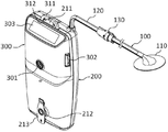
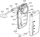
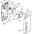
1 is a perspective view showing an overall appearance of an indirect suction type portable aspirator according to the present invention.
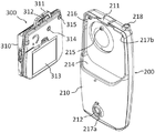
FIG. 2 is a perspective view of a vacuum pump module and a drain container of an indirect suction type portable aspirator according to the present invention. FIG.
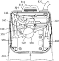
3 is an internal layout view of the vacuum pump module of the indirect suction type portable aspirator according to the present invention.
FIG. 4 is a perspective view showing the inside of the drainage container of the indirect suction type portable aspirator according to the present invention separated into a front portion and a rear portion.
FIG. 5 is a perspective view illustrating a vacuum operation fluid pump installed in a front and a rear part of a drain container of an indirect suction type portable aspirator according to the present invention. FIG.
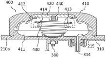
6 is a cross-sectional view showing the structure of a vacuum operation fluid pump provided in the indirect suction type portable aspirator according to the present invention.
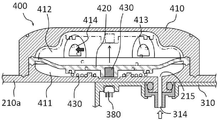
FIG. 7 is a sectional view showing the suction operation state of the vacuum operating fluid pump shown in FIG. 6. FIG.
8 is a sectional view showing the discharging operation state of the vacuum operating fluid pump shown in FIG.
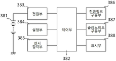
9 is a block diagram of a control circuit block of the indirect suction type portable aspirator according to the present invention.
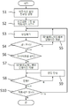
10 is a control flowchart of the indirect suction type portable aspirator according to the present invention.
Hereinafter, preferred embodiments of the present invention will be described in detail with reference to the accompanying drawings. The accompanying drawings are merely illustrative of preferred embodiments of the present invention and are not intended to limit the present invention. In addition, some elements may be exaggerated or omitted in the drawings, and may differ from actual ones.
The portable aspirator according to the present invention illustrated in FIG. 1 includes a
Referring to FIG. 2, a
3, the
Referring to FIG. 4, the vacuum
5, the vacuum
6 to 9, the
The
6, the
7, the
The action of generating the negative pressure and exchanging the body fluids such as the exudates is periodically repeated in order to transmit and exhaust the vacuum pressure to the
9 shows a control circuit configuration mounted on the
Next, Fig. 10 is a flowchart illustrating the control operation by the above-described control circuit. Step S1 is a step of setting the operating conditions such as the operating time and the vacuum pressure. Step S2 is a step of starting driving of the vacuum pump for generating the vacuum pressure and counting the operation time thereof. Steps S3 to S5 are control procedures for opening the above-described
The main feature of the present invention as described through the above embodiments is that the vacuum pressure generated in the
The present invention relates to a vacuum pump and a vacuum pump which are capable of effectively and effectively controlling the amount of air discharged from a vacuum pump, The vacuum pump according to any one of claims 1 to 3, further comprising: a solenoid valve (360), a negative pressure sensor (370), a Hall sensor (400), a vacuum operation fluid pump (410), a housing (411), a vacuum chamber (412), a bodily fluid chamber (413), a suction port (414) 430: spring member, 440: magnet, 450: 460: check valve
Claims (7)
Applications Claiming Priority (2)
| Application Number | Priority Date | Filing Date | Title |
|---|---|---|---|
| KR20150028739 | 2015-02-28 | ||
| KR1020150028739 | 2015-02-28 |
Publications (1)
| Publication Number | Publication Date |
|---|---|
| KR20160105709A true KR20160105709A (en) | 2016-09-07 |
Family
ID=56949864
Family Applications (1)
| Application Number | Title | Priority Date | Filing Date |
|---|---|---|---|
| KR1020150046452A KR20160105709A (en) | 2015-02-28 | 2015-04-01 | Indirect suction type portable aspirator |
Country Status (1)
| Country | Link |
|---|---|
| KR (1) | KR20160105709A (en) |
Cited By (2)
| Publication number | Priority date | Publication date | Assignee | Title |
|---|---|---|---|---|
| CN106267393A (en) * | 2016-10-25 | 2017-01-04 | 温州康普特生物科技有限公司 | Treatment of wounds survival kit |
| KR101940792B1 (en) | 2018-04-24 | 2019-01-22 | 서현배 | Control method of multi-vacuum operation body fluid pump |
Citations (10)
| Publication number | Priority date | Publication date | Assignee | Title |
|---|---|---|---|---|
| KR100509075B1 (en) | 2001-09-24 | 2005-08-17 | 이종우 | Innalating equipment of excreting things to operate which is controleding the pressure by electricity |
| US7004915B2 (en) | 2001-08-24 | 2006-02-28 | Kci Licensing, Inc. | Negative pressure assisted tissue treatment system |
| KR20100015999A (en) | 2007-05-22 | 2010-02-12 | 메델라 홀딩 아게 | Drainage pump unit |
| KR100978599B1 (en) | 2010-03-22 | 2010-08-27 | 주식회사 아이베이지디쓰리 | Portable discharging device for body-fluid and control method thereof |
| KR200456798Y1 (en) | 2008-12-16 | 2011-11-21 | 메디플랜(주) | Wall Suction Unit |
| KR101144422B1 (en) | 2007-05-10 | 2012-05-10 | 케이씨아이 라이센싱 인코포레이티드 | Reduced pressure wound dressing having a wound contact surface with columnar protrusions |
| KR101198563B1 (en) | 2006-03-14 | 2012-11-06 | 케이씨아이 라이센싱 인코포레이티드 | System and method for percutaneously administering reduced pressure treatment using a flowable manifold |
| KR101212650B1 (en) | 2012-05-31 | 2012-12-14 | 양정곤 | A medical suction unit |
| KR101309063B1 (en) | 2011-08-11 | 2013-09-16 | 재단법인 아산사회복지재단 | Drainage bag and manufacturing process of the same |
| KR101497776B1 (en) | 2008-02-29 | 2015-03-05 | 케이씨아이 라이센싱 인코포레이티드 | A device and method for collecting exudates |
-
2015
- 2015-04-01 KR KR1020150046452A patent/KR20160105709A/en unknown
Patent Citations (10)
| Publication number | Priority date | Publication date | Assignee | Title |
|---|---|---|---|---|
| US7004915B2 (en) | 2001-08-24 | 2006-02-28 | Kci Licensing, Inc. | Negative pressure assisted tissue treatment system |
| KR100509075B1 (en) | 2001-09-24 | 2005-08-17 | 이종우 | Innalating equipment of excreting things to operate which is controleding the pressure by electricity |
| KR101198563B1 (en) | 2006-03-14 | 2012-11-06 | 케이씨아이 라이센싱 인코포레이티드 | System and method for percutaneously administering reduced pressure treatment using a flowable manifold |
| KR101144422B1 (en) | 2007-05-10 | 2012-05-10 | 케이씨아이 라이센싱 인코포레이티드 | Reduced pressure wound dressing having a wound contact surface with columnar protrusions |
| KR20100015999A (en) | 2007-05-22 | 2010-02-12 | 메델라 홀딩 아게 | Drainage pump unit |
| KR101497776B1 (en) | 2008-02-29 | 2015-03-05 | 케이씨아이 라이센싱 인코포레이티드 | A device and method for collecting exudates |
| KR200456798Y1 (en) | 2008-12-16 | 2011-11-21 | 메디플랜(주) | Wall Suction Unit |
| KR100978599B1 (en) | 2010-03-22 | 2010-08-27 | 주식회사 아이베이지디쓰리 | Portable discharging device for body-fluid and control method thereof |
| KR101309063B1 (en) | 2011-08-11 | 2013-09-16 | 재단법인 아산사회복지재단 | Drainage bag and manufacturing process of the same |
| KR101212650B1 (en) | 2012-05-31 | 2012-12-14 | 양정곤 | A medical suction unit |
Cited By (2)
| Publication number | Priority date | Publication date | Assignee | Title |
|---|---|---|---|---|
| CN106267393A (en) * | 2016-10-25 | 2017-01-04 | 温州康普特生物科技有限公司 | Treatment of wounds survival kit |
| KR101940792B1 (en) | 2018-04-24 | 2019-01-22 | 서현배 | Control method of multi-vacuum operation body fluid pump |
Similar Documents
| Publication | Publication Date | Title |
|---|---|---|
| ES2683627T3 (en) | Method of collection and disposal of liquid waste | |
| US10076592B2 (en) | System for aspirating fluids from a body using negative pressure | |
| JP6026470B2 (en) | Apparatus and method for applying reduced pressure treatment to a tissue site | |
| JP4970445B2 (en) | Wound cover and drainage system | |
| CN101336117B (en) | Suctioning system, method and kit | |
| US20090005746A1 (en) | Suction System | |
| US20090036873A1 (en) | Device, Pump and System for Stimulating the Healing of a Wound | |
| KR20190026858A (en) | Flexible negative pressure system | |
| US20090012484A1 (en) | Pump and System for Treatment of a Wound | |
| US20110160683A1 (en) | Device for controlling and monitoring vacuum pressure in systems for the suction of biological secretions | |
| KR100978599B1 (en) | Portable discharging device for body-fluid and control method thereof | |
| EP3189860A1 (en) | Motorized chest drainage system | |
| JP2009502301A (en) | Suction system, method and kit | |
| CN104826178A (en) | Reduced-pressure dressing connection pads, systems, and methods | |
| JPH04507057A (en) | Device for continuous perfusion and drainage of tissues or cavities of a human or animal organism | |
| KR20160105709A (en) | Indirect suction type portable aspirator | |
| KR20160115619A (en) | Indirect suction type vacuum drainage system | |
| JP2017143967A (en) | Living body washer and living body washing method | |
| JP5629155B2 (en) | Negative pressure therapy device | |
| KR101771227B1 (en) | Medical suction unit | |
| RU125446U1 (en) | ENDOSCOPE FLUID CONTROL DEVICE | |
| RU2322268C1 (en) | Drainage device and method of removing liquid from body's cavity | |
| RU2523354C2 (en) | Endoscope fluid control device and endoscope | |
| RU2734443C1 (en) | Device for treating infected and purulent wounds | |
| KR101940792B1 (en) | Control method of multi-vacuum operation body fluid pump |