KR20160085746A - Pinless piston with gallery - Google Patents
Pinless piston with gallery Download PDFInfo
- Publication number
- KR20160085746A KR20160085746A KR1020167008562A KR20167008562A KR20160085746A KR 20160085746 A KR20160085746 A KR 20160085746A KR 1020167008562 A KR1020167008562 A KR 1020167008562A KR 20167008562 A KR20167008562 A KR 20167008562A KR 20160085746 A KR20160085746 A KR 20160085746A
- Authority
- KR
- South Korea
- Prior art keywords
- piston
- connecting rod
- gallery
- boss
- Prior art date
Links
Images


Classifications
-
- F—MECHANICAL ENGINEERING; LIGHTING; HEATING; WEAPONS; BLASTING
- F02—COMBUSTION ENGINES; HOT-GAS OR COMBUSTION-PRODUCT ENGINE PLANTS
- F02F—CYLINDERS, PISTONS OR CASINGS, FOR COMBUSTION ENGINES; ARRANGEMENTS OF SEALINGS IN COMBUSTION ENGINES
- F02F3/00—Pistons
- F02F3/16—Pistons having cooling means
- F02F3/20—Pistons having cooling means the means being a fluid flowing through or along piston
-
- F—MECHANICAL ENGINEERING; LIGHTING; HEATING; WEAPONS; BLASTING
- F02—COMBUSTION ENGINES; HOT-GAS OR COMBUSTION-PRODUCT ENGINE PLANTS
- F02F—CYLINDERS, PISTONS OR CASINGS, FOR COMBUSTION ENGINES; ARRANGEMENTS OF SEALINGS IN COMBUSTION ENGINES
- F02F3/00—Pistons
-
- F—MECHANICAL ENGINEERING; LIGHTING; HEATING; WEAPONS; BLASTING
- F16—ENGINEERING ELEMENTS AND UNITS; GENERAL MEASURES FOR PRODUCING AND MAINTAINING EFFECTIVE FUNCTIONING OF MACHINES OR INSTALLATIONS; THERMAL INSULATION IN GENERAL
- F16J—PISTONS; CYLINDERS; SEALINGS
- F16J1/00—Pistons; Trunk pistons; Plungers
- F16J1/09—Pistons; Trunk pistons; Plungers with means for guiding fluids
-
- F—MECHANICAL ENGINEERING; LIGHTING; HEATING; WEAPONS; BLASTING
- F16—ENGINEERING ELEMENTS AND UNITS; GENERAL MEASURES FOR PRODUCING AND MAINTAINING EFFECTIVE FUNCTIONING OF MACHINES OR INSTALLATIONS; THERMAL INSULATION IN GENERAL
- F16J—PISTONS; CYLINDERS; SEALINGS
- F16J1/00—Pistons; Trunk pistons; Plungers
- F16J1/10—Connection to driving members
- F16J1/14—Connection to driving members with connecting-rods, i.e. pivotal connections
- F16J1/22—Connection to driving members with connecting-rods, i.e. pivotal connections with universal joint, e.g. ball-joint
-
- F—MECHANICAL ENGINEERING; LIGHTING; HEATING; WEAPONS; BLASTING
- F02—COMBUSTION ENGINES; HOT-GAS OR COMBUSTION-PRODUCT ENGINE PLANTS
- F02F—CYLINDERS, PISTONS OR CASINGS, FOR COMBUSTION ENGINES; ARRANGEMENTS OF SEALINGS IN COMBUSTION ENGINES
- F02F3/00—Pistons
- F02F2003/0007—Monolithic pistons; One piece constructions; Casting of pistons
Abstract
피스톤 어셈블리는 피스톤 부재 및 커넥팅 로드를 가진다. 피스톤 부재는 크라운부 및 함께 접합되는 하부 부분을 가지고, 냉각 갤러리는 크라운부와 하부 부분 사이에 형성되어 있다. 커넥팅 로드는 피스톤 부재 내의 소켓에 위치결정되어 있는 볼 단부를 가진다. 일 실시예에서, 볼 단부는 2개의 평평한 표면을 가질 수 있고, C-클립에 의해 적소에 보유될 수 있다. 다른 실시예에서, 볼 단부는 실린더 형상이고, 소켓은 대응하는 형상을 가진다.The piston assembly has a piston member and a connecting rod. The piston member has a crown portion and a lower portion joined together, wherein the cooling gallery is formed between the crown portion and the lower portion. The connecting rod has a ball end positioned in the socket in the piston member. In one embodiment, the ball end can have two flat surfaces and can be held in place by a C-clip. In another embodiment, the ball end is cylindrical and the socket has a corresponding shape.

Description
본 출원은 2013년 9월 16일자로 출원된 미국가출원 제61/878,507호 및 2014년 9월 16일자로 출원된 미국 실용신안출원 제14/487,498호의 이익을 주장하고, 이들 모두는 전체로 참조사항으로 본 명세서에 통합되어 있다. This application claims the benefit of U.S. Provisional Application No. 61 / 878,507, filed September 16, 2013, and U.S. Utility Model Application Ser. No. 14 / 487,498, filed September 16, 2014, both of which are incorporated by reference in their entirety Which is incorporated herein by reference.
본 발명은 대체로 내연 기관에 관한 것이고, 보다 상세하게는 내연 기관용 피스톤 및 연결 부재에 관한 것이다BACKGROUND OF THE INVENTION 1. Field of the Invention The present invention relates generally to an internal combustion engine, and more particularly to a piston and a connecting member for an internal combustion engine
내연 기관에는 피스톤, 및 커넥팅 로드의 소단부의 피스톤에 대한 조작가능한 연결을 위하여 리스트 핀(wrist pin)의 사용을 필요로 하는 커넥팅 로드 어셈블리가 있다는 것은 알려져 있다. 특히, 피스톤 구성은 한 쌍의 핀 보스가 있는 피스톤 바디를 포함하는 것으로 알려져 있는데, 한 쌍의 핀 보스는 피스톤 바디의 크라운으로부터, 서로 측면방향으로 이격되어 있는 한 쌍의 축방향으로 정렬된 핀 보어 쪽으로 늘어져 있다. 회전 운동을 피스톤의 직선 운동으로 전환하기 위하여, 커넥팅 로드의 대단부는 엔진의 크랭크샤프트에 부착되고, 커넥팅 로드의 소단부는 리스트 핀을 이용하여 피스톤에 대한 조작가능한 부착을 위하여 핀 보스들 사이에 수용된다. 리스트 핀과 핀 보어 사이의 마찰을 줄이는 것을 촉진하기 위하여, 저널 베어링을 핀 보어 내부에 삽입하는 것은 알려져 있다. 이러한 피스톤 및 커넥팅 로드 어셈블리가 널리 받아들여지고 있고 유용하지만, 특정 목표들, 예컨대 중량을 줄이는 것, 제조 효율을 향상시키는 것 및 부품 비용을 줄이는 것을 달성하기 위하여 지속적인 노력이 행해지고 있다. It is known that the internal combustion engine has a connecting rod assembly requiring the use of a piston and a wrist pin for operable connection to the piston of the small end of the connecting rod. In particular, the piston arrangement is known to include a piston body with a pair of pin bosses, wherein the pair of pin bosses are spaced apart from a crown of the piston body by a pair of axially aligned pin bores . In order to convert the rotational motion into a linear motion of the piston, the large end of the connecting rod is attached to the crankshaft of the engine, and the small end of the connecting rod is accommodated between the pin bosses for operable attachment to the piston do. To facilitate reducing friction between the wrist pin and the pin bore, it is known to insert the journal bearing inside the pin bore. While such piston and connecting rod assemblies are widely accepted and useful, there is a continuing effort to achieve certain goals, such as reducing weight, improving manufacturing efficiency, and reducing component cost.
피스톤은 커넥팅 로드와 피스톤 바디 사이에 리스트 핀 연결의 필요가 없는 것으로 알려져 있다. 이러한 피스톤 구성은 커넥팅 로드에 대한 피스톤 바디의 직접 부착을 제공한다. 피스톤은 실린더형 또는 구형 포켓과 함께 그 안에 형성된 단일의 보어가 있는 피스톤 바디의 크라운으로부터 늘어져 있는 보스를 가진다. 커넥팅 로드는 생크가 소단부 쪽으로 뻗어있는 상태로 종래의 피스톤과 대체로 동일하게 구성된다. 소단부는 리스트 핀 보어를 제공하지는 않지만, 보어 포켓에 수용하기 위한 실린더형 또는 구형 표면을 제공하도록 생크의 측면으로부터 측면방향 바깥쪽으로 뻗어있는 외측 표면을 가진다.The piston is known to have no need for a wrist pin connection between the connecting rod and the piston body. This piston arrangement provides direct attachment of the piston body to the connecting rod. The piston has a boss extending from the crown of the piston body with a single bore formed therein with a cylindrical or spherical pocket. The connecting rod is constructed substantially the same as the conventional piston with the shank extending toward the small end. The small end does not provide a wrist pin bore but has an outer surface that extends laterally outwardly from the side of the shank to provide a cylindrical or spherical surface for receiving in the bore pocket.
본 발명에 따라 구성된 피스톤은 리스트 핀이 필요없고, 위에 언급된 목표의 달성 뿐만 아니라 피스톤 어셈블리에 관한 기술분야에서의 통상의 기술자가 용이하게 이해할 수 있는 다른 것을 더욱 개선시킨다. 본 발명의 목적은 또한 비교적 중량이 가벼울 뿐만 아니라(즉 작은 질량을 가짐) 과열을 방지하도록 적절히 냉각될 수 있는 개선된 스틸 피스톤을 제공하는 것이다. The piston constructed in accordance with the present invention does not require a list pin and further improves other things that one of ordinary skill in the art of piston assembly will readily understand as well as achieving the above mentioned goals. It is also an object of the present invention to provide an improved steel piston that is not only relatively light in weight (i.e., has a small mass) and can be adequately cooled to prevent overheating.
피스톤 및 커넥팅 로드 어셈블리는 상부 크라운과 함께 중심 축을 따라 뻗어있는 피스톤 바디, 및 중심 축을 따라 크라운으로부터 늘어져 있는 보스를 포함한다. 보스는 자유 단부 쪽으로 중심 축의 양쪽 측면들을 따라 뻗어있는 마주하는 측면들 뿐만 아니라, 커넥팅 로드의 소단부의 수용을 위한 포켓을 가진다. 보스는 자유 단부를 통해 포켓 속으로 뻗어있는 개구를 더 포함한다. 어셈블리는 포켓에 수용하도록 구성된 볼 타입 형상의 소단부에서 종료하는 커넥팅 로드를 더 포함하고, 생크는 크랭크샤프트에 조작가능하게 부착하도록 구성된 타단부 쪽으로 뻗어있다. The piston and connecting rod assembly includes a piston body extending along a central axis with an upper crown, and a boss extending from the crown along the central axis. The boss has pockets for receiving the small end of the connecting rod, as well as the facing sides extending along both sides of the central axis towards the free end. The boss further includes an opening extending through the free end into the pocket. The assembly further includes a connecting rod terminating in a ball-shaped, small end configured to be received in the pocket, the shank extending toward the other end configured to operably attach to the crankshaft.
피스톤은, 강도와 내구성을 제공할 뿐만 아니라 스틸이 아닌 피스톤 보다 고온 및 고압을 잘 견딜 수 있는 스틸 재료로 만들어진다. 피스톤은 2개의 부분, 즉 상부 크라운부와 하부 보스 내지 바디부가 만들어져 있다. 이 부분들 중 하나 또는 모두는 단조 또는 균등한 제조 공정으로 만들어질 수 있다. 상부 크라운부는 연소 보울의 일부나 모두를 포함하고, 측벽부 상에 하나 이상의 링 그루브를 포함할 수 있다. 하부 바디부는 측벽들을 포함하고, 하나 이상의 링 그루브를 포함할 수 있다. The piston is made of a steel material that not only provides strength and durability but also can withstand higher temperatures and pressures than non-steel pistons. The piston has two parts, an upper crown part and a lower boss or body part. One or both of these parts may be made in a forged or equivalent manufacturing process. The upper crown portion includes part or all of the combustion bowl and may include one or more ring grooves on the side wall portion. The lower body portion includes sidewalls, and may include one or more ring grooves.
2개의 부분들은 마찰 용접이나 유도 용접과 같은 것에 의해 함께 영구적으로 접합된다. 냉각 갤러리는 크라운부와 바디부 사이에 제공된다. 냉각 갤러리를 통해 순환되거나 냉각 갤러리 속으로 순환되는 오일은 상부 크라운부와 그 림을 과열되지 않도록 유지한다. The two parts are permanently joined together, such as by friction welding or induction welding. A cooling gallery is provided between the crown portion and the body portion. The oil circulated through the cooling gallery or circulated into the cooling gallery keeps the upper crown part and the rim not overheated.
본 발명의 일 실시예에 따르는 피스톤 및 커넥팅 로드의 조립 동안, 볼 단부는 커넥팅 로드의 조작 포지션으로부터 90°회전된 보스의 하부 개방 단부로부터 삽입된다. 이는 볼 단부의 편평부가 포켓으로 들어가게 한다. 로드는 이때 그 조작 포지션으로 90°회전된다. 한 쌍의 C-클립은 피스톤이 로드에 대하여 회전하는 것을 방지하도록 적소에 설치된다. During assembly of the piston and connecting rod in accordance with an embodiment of the present invention, the ball end is inserted from the lower open end of the boss rotated 90 [deg.] From the operating position of the connecting rod. This allows the flat portion of the ball end to enter the pocket. At this time, the rod is rotated by 90 ° to its operating position. A pair of C-clips is installed in place to prevent the piston from rotating relative to the rod.
본 발명의 다른 실시예는 상부 단부 내지 소단부에 있는 실린더형 부재가 있는 커넥팅 로드, 및 실린더 형상의 소켓이 있는 피스톤 부재를 포함한다. 이 실시예에서, 커넥팅 로드는 소단부를 커넥팅 로드의 길이 방향에 대해 횡단방향으로 소켓 속으로 미끄럼이동시킴으로써 피스톤 부재에 연결된다. Another embodiment of the present invention includes a connecting rod with a cylindrical member at the upper end to a smaller end, and a piston member with a cylindrical socket. In this embodiment, the connecting rod is connected to the piston member by sliding the small end portion into the socket in the transverse direction with respect to the longitudinal direction of the connecting rod.
본 발명에 따라 제조된 피스톤 및 커넥팅 로드 어셈블리는 피스톤에 관한 당해 기술분야에서의 통상의 기술자가 용이하게 이해할 수 있는 다른 것들 중에서 피스톤 어셈블리 내의 구성요소의 개수를 줄이고, 피스톤 어셈블리의 압축 높이를 줄이고, 피스톤 어셈블리의 왕복 질량을 감소시키고, 피스톤 어셈블리와 관련 구성요소들에 긴 유효 수명을 제공한다. The piston and connecting rod assemblies made in accordance with the present invention can be used to reduce the number of components in the piston assembly, reduce the compression height of the piston assembly, and the like, among other things that would be readily apparent to one of ordinary skill in the art with respect to the piston, Reduces the reciprocating mass of the piston assembly, and provides long service life for the piston assembly and associated components.
본 발명의 다른 특징과 세부사항은 첨부된 도면과 첨부의 청구범위에 따라 살펴보면 다음에 오는 발명의 상세한 설명으로부터 자명하게 될 수 있을 것이다.Other features and details of the present invention will become apparent from the following detailed description when read in conjunction with the accompanying drawings and the appended claims.
본 발명의 여러 가지 양태, 특징 및 이점은 현재의 바람직한 실시예, 첨부의 청구범위 및 첨부된 도면에 관한 다음의 상세한 설명의 관점에서 당해 기술분야에서의 통상의 기술자에게 용이하게 자명할 것이다.
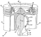
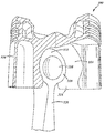
도 1은 본 발명에 따르는 피스톤 및 커넥팅 로드의 예시적인 실시예의 일부 절단면의 사시도이다.
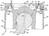
도 2는 도 1에 나타나 있는 바와 같은 본 발명의 예시적인 실시예의 단면도이다.
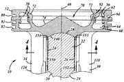
도 3은 도 1에 나타나 있는 바와 같은 본 발명의 예시적인 실시예의 단면도이다.
도 4는 도 3에서 화살표 방향으로 라인 4-4를 따라 절단한, 도 3에 나타나 있는 실시예의 단면도이다.
도 5는 본 발명에 따르는 피스톤 및 커넥팅 로드의 예시적인 실시예에 관한 도 1의 다른 사시도이다.
도 6, 도 7 및 도 8에는 본 발명의 대체 실시예가 도시되어 있다.
도 9, 도 10 및 도 11에는 본 발명의 다른 대체 실시예가 도시되어 있다.Various aspects, features, and advantages of the present invention will be readily apparent to those of ordinary skill in the art in light of the presently preferred embodiments, the appended claims, and the following detailed description of the accompanying drawings.
BRIEF DESCRIPTION OF THE DRAWINGS Figure 1 is a perspective view of some cross-sections of an exemplary embodiment of a piston and connecting rod according to the present invention.
2 is a cross-sectional view of an exemplary embodiment of the present invention as shown in FIG.
Figure 3 is a cross-sectional view of an exemplary embodiment of the present invention as shown in Figure 1;
Fig. 4 is a cross-sectional view of the embodiment shown in Fig. 3 cut along line 4-4 in the direction of the arrow in Fig.
Figure 5 is another perspective view of Figure 1 in relation to an exemplary embodiment of a piston and connecting rod according to the present invention.
6, 7 and 8 show an alternative embodiment of the present invention.
9, 10 and 11 show another alternative embodiment of the present invention.
도면을 참조하면, 여기서 유사한 부재번호는 몇몇 도면에 걸쳐 대응하는 부분을 지시하고, 피스톤 및 커넥팅 로드 어셈블리(10)가 나타나 있다. 이 어셈블리(10)는 본 발명의 예시적인 실시예일 뿐이고, 본 발명의 유일한 실시예로 보아서는 안된다. 본 발명은 결과적으로는 특허에서 문제되기 때문에 특허청구범위에 의해 제한될 뿐이고, 다음에 오는 발명의 상세한 설명에서 특별히 기술되거나 도면에 나타나 있는 바와 같은 특징이나 세부사항에 의해 제한되지 않는다.Referring now to the drawings, wherein like reference numerals designate corresponding parts throughout the several views, a piston and connecting
어셈블리(10)는 피스톤(30) 및 커넥팅 로드(20)를 포함한다. 피스톤(30)은 기다란 중심 축(40)을 가진다. 커넥팅 로드(20) 또한 기다란 중심 축(50)을 가진다. 2개의 축들은 도 3에 나타나 있는 바와 같이 커넥팅 로드가 피스톤에 대해 수직으로 위치될 때 정렬된다. The assembly (10) includes a piston (30) and a connecting rod (20). The piston (30) has an elongated central axis (40). The connecting
도면에서, 도 1은 어셈블리(10)의 일부가 절단된 예시적인 실시예이다. 이 도면에는 피스톤과 커넥팅 로드의 연결을 보여주기 위하여 절단면이 있다. 도 2와 도 3은 도 1에 나타나 있는 예시적인 실시예의 단면도이고, 2개의 단면도는 서로에 대해 90°절단되어 있다. 도 4는 도 3의 라인 4-4를 따라 절단한 단면도이고, 피스톤의 바닥으로부터 크라운을 향하여 위로 바라본 것이다. 도 5는 대체로 피스톤의 바닥으로부터 어셈블리(10)를 바라본 도 1 실시예의 사시도이다.In the figure, Figure 1 is an exemplary embodiment in which a portion of the
커넥팅 로드(20)는 피스톤을 엔진(미도시)의 크랭크샤프트에 연결하는데 사용된다. 커넥팅 로드는 커넥팅 로드를 크랭크샤프트에 부착하는 대단부(미도시)를 가진다. 커넥팅 로드의 대단부는 오늘날 잘 알려진 커넥팅 로드와 유사하거나 동일해서, 본 명세서에서 추가적인 설명은 필요하지 않는다. The connecting
커넥팅 로드(20)의 상부 단부 내지 소단부(22)는 도 1 내지 도 3 및 도 5에 나타나 있다. 소단부(22)는 커넥팅 로드의 "볼 단부(ball end)"로도 불린다. 볼 단부(22)는 2개의 편평한 측면들(24, 26), 및 2개의 편평한 측면들 사이에 있는 구형상부(28)를 가진다. 커넥팅 로드(20)는 또한 바람직하게는 로드(20)의 주된 자루부(21)와 볼 단부(22) 사이에 좁은 "넥타입(neck-type)" 부위(29)를 가진다. The upper end to the
커넥팅 로드(20)는 통상적으로 스틸이나 내구성 좋은 금속 재료로 만들어지고, 모두 산업분야에 알려진 바와 같이 기계가공되거나 단조가공되거나 전력공급되는 금속 가공으로 만들어질 수 있다. The connecting
피스톤 부재(30)는 2개의 부분, 즉 상부 내지 크라운부(32) 및 하부 내지 바디부(34)로 이루어진다. 바디부는 스커트부로도 불린다. 이 모든 부분들은 스틸 재료로 만들어지고, 바람직하게는 단조 공정으로 만들어진다. 2개의 부분들(32, 34)은 필요한 만큼 기계가공되거나 마감처리되고 나서, 피스톤 부재(30)를 형성하도록 함께 영구적으로 접합된다. 이 2개의 부분들은 바람직하게는 마찰 용접이나 유도 용접에 의해 함께 결합된다. 도 1 내지 도 3에 나타나 있는 곡선형 돌기(curved tailing)(36)는 전형적으로 마찰 용접 공정으로 된다. The
냉각 갤러리(60)는 크라운부(32)와 바디부(34)가 함께 접합되는 경우 피스톤 부재(30) 내에 형성된다. 냉각 갤러리의 상부 부분(62)은 크라운부(32) 내에 형성되고, 하부 부분(64)은 바디부(34) 내에 형성된다. 나타나 있는 예시적인 실시예에서, 연소 보울(70)은 또한 2개의 피스톤 부분들(32, 34)에 포함된 2개의 부분들(72, 74)에 의해 형성된다. 다른 실시예들에서, 연소 보울은 전체적으로 크라운부 내지 하부 부분 내에 형성될 수 있다. The cooling
추가적으로, 나타나 있는 예시적인 실시예에서, 피스톤 링을 위한 그루브(80, 81, 82)는 2개의 부분들(32, 34) 각각에 부분적으로 제공되어 있다. 다른 실시예에서는 크라운부 내지 스커트부 중 하나 또는 나머지에 있는 모든 링 그루브를 포함하는 것도 가능하다. Additionally, in the illustrated exemplary embodiment, the
크라운부와 하부 부분을 함께 효율적으로 마찰 용접하기 위하여 짝이되는 환형 표면들(92, 94)이 제공된다. 이는 도 2와 도 3에 상세하게 나타나 있다.Coupled
2개의 부분이 함께 접합되는 경우라면, 외측 측벽 표면과 연소 보울 표면은 접합 공정으로부터 형성되는 돌기 잔여물을 제거하도록 기계가공된다. 냉각 갤러리(60) 내의 곡선형 돌기(36)는 제거되지 않는다.If the two parts are joined together, the outer sidewall surface and the combustion bowl surface are machined to remove projections residues formed from the joining process. The
냉각 오일이 냉각 갤러리 속으로 도입되게 하고 냉각 갤러릴부터 배출되게 하기 위하여, 개구들(100, 102)이 제공된다. 이들은 통상적으로 피스톤의 2개의 부분들이 함께 접합되기 전에 드릴가공되거나 기계가공된다. 이는 도 4에도 나타나 있다. 개구(102)는 유입 개구이고, 특히 오일을 공급하는 오일 제트가 일정한 각도로 오일을 분무하는 경우라면 나타나 있는 바와 같이 타원 형상을 가질 수 있다.
하부 부분이 형성되는 경우에는 2개의 마주하는 기다란 보스 부재들(110, 120)을 가진다. 이들은 바람직하게는 도 5에 나타나 있는 바와 같이 중공형이면서 대체로 실린더 형상의 부재이다. 이 부재들은 피스톤(30)을 형성하는데 요구되는 측벽과 구조가 추가되고, 피스톤의 중량 내지 질량을 줄이기 위해서 주로 중공형이다. 중공형 보스 부재들(110, 120)은 또한 오일 유입 개구(100)와 유출 개구(102)를 형성하도록 냉각 갤러리 쪽으로의 접근을 허용한다. And two opposing
2개의 개구가 오일을 도입하도록 그리고 오일을 배출하도록 냉각 갤러리 내에 나타나 있지만, 정확한 개수는 중요하지 않다. 개구의 개수, 크기 및 형상은 오일의 유입 및 유출을 위하여 동일할 필요도 없다. Although the two openings are shown in the cooling gallery to introduce oil and to drain the oil, the exact number is not important. The number, size and shape of the openings need not be the same for the inflow and outflow of oil.
바람직한 실시예에 나타나 있는 냉각 갤러리(60)는 "폐쇄형(closed)" 오일 갤러리이다. 본 발명의 대체 실시예에 따라, 바닥 부재가 없는 "개방형(open)" 갤러리를 제공하는 것도 가능하다. The cooling
복수의 슬롯(120)은 최하부 링 그루브(81)로부터 오일을 배출하기 위하여 피스톤(30)에 제공되어 있다. 이들은 도 4와 도 5에 도시되어 있다.A plurality of slots (120) are provided in the piston (30) for draining oil from the lowermost ring groove (81). These are shown in FIG. 4 and FIG.
커넥팅 로드(20)의 볼 단부(22)로부터 피스톤 내의 소켓(140)("포켓"으로도 불림)은 피스톤의 하부 부분(34)과 연소 보울(70)의 바로 아래에서 기계가공된다. 도면에 나타나 있는 바와 같이, 포켓은 볼 단부 상의 곡선 표면(28)과 일치하도록 구형 형상을 가진다. 피스톤 어셈블리(10)가 엔진에서 사용 중인 경우, 볼 단부는 각각의 스트로크 동안 포켓 내에서 피벗한다. The socket 140 (also referred to as a "pocket") in the piston from the ball end 22 of the connecting
한 쌍의 C-클립(150, 152)은 커넥팅 로드(20)가 피스톤 부재(30)로부터 분리되는 것을 방지하도록 제공된다. C-클립은 동력부(34) 내에 형성된 그루브(151, 153) 내에 위치결정되어 있다. 커넥팅 로드를 피스톤 바디 내에 고정하거나 보유하는 다른 방법도 이용될 수 있다. The pair of C-
피스톤 어셈블리(10)가 조립되는 경우, 커넥팅 로드(20)는 그 조작 포지션으로부터 길이방향으로 90°회전되어서, 볼 단부는 포켓(140) 내에 위치결정될 수 있다. 볼 단부(22)의 단부가 포켓 내에 위치결정되면, 커넥팅 로드(20)는 그 조작 포지션 쪽으로 길이방향으로 90°회전된다. 이는 도 1 내지 도 3 및 도 5에 나타나 있다. 이후, C-클립(150, 152)은 피스톤 부재(30)에 대한 커넥팅 로드(20)의 추가적이고 상대적인 길이방향 회전을 방지하기 위해서 적소에 설치된다.When the
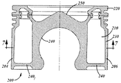
도 6 내지 도 8에는 본 발명의 대체 실시예가 도시되어 있다. 도 6은 단면도이고, 도 7은 도 6에서 화살표 방향으로 라인 7-7을 따라 절단된 도면이고, 도 8은 피스톤의 바닥에 관한 도면이다.6-8 illustrate an alternative embodiment of the present invention. Fig. 6 is a cross-sectional view, Fig. 7 is a view cut along the line 7-7 in the direction of the arrow in Fig. 6, and Fig. 8 is a view showing the bottom of the piston.
대체 피스톤 실시예는 부재번호 200으로 지칭된다. 피스톤(200)은 주로 냉각 갤러리(210)의 크기와 구조에 관하여 상술된 피스톤 실시예(10)와 상이하다. 피스톤(200)의 다른 특징들은, 2개의 단조된 구역(크라운부(220)와 하부 바디부(230))을 함께 접합하는 것, 커넥팅 로드의 볼 타입 단부를 위한 포켓(240)을 제공하는 것, 볼 타입 단부를 유지 부재로 피스톤 내에 유지하는 것을 포함하는데, 상술된 바와 같이 모두 동일하다. The alternative piston embodiment is referred to as
냉각 갤러리(210)는 실질적으로 보스 부재(204, 206)의 전체 길이(높이) 만큼 뻗어있다. 냉각 갤러리(210)의 바닥 벽(240)들은 크라운부(200)와 연소 보울(250)로부터 피스톤의 양쪽 단부에 있는 보스 부재들(204, 206)의 하부 단부들에 위치되어 있다.The
개구들(260, 270)은 냉각 갤러리(210) 속으로의 냉각 오일의 유입 및 냉각 갤러리(210)로부터의 냉각 오일의 유출을 위하여 바닥 벽(240)들에 만들어져 있다. 이들은 실질적으로 도 1 내지 도 5에 관하여 상술된 개구들(100, 102)과 동일한 것이다.The openings 260 and 270 are made in the
보스 부재들(204, 206) 내의 하부 벽(240)들의 포지션은 냉각 갤러리(210) 내의 오일이 냉각 갤러리의 상부 표면과 접촉하거나 부딪히기 전에 고속에 도달하게 하고, 이는 오일의 냉각 효과를 증가시킬 수 있다.The position of the
추가적으로, 냉각 갤러리의 하부 벽(240)들은 스커트부의 바닥 근처에 위치결정되고, 스커트는 더 딱딱해질 것이다. 스커트의 바닥이 더 딱딱한 상태에서, 피스톤은 조작 동안 덜 흔들릴 것이다. Additionally, the
하부 갤러리를 스커트부의 바닥이나 그 근처에 위치결정하는 것은 또한 피스톤의 기계가공에 유리하다. 이는 더욱 양호한 공차를 허용할 것인데, 스커트의 바닥의 굴절이 감소되기 때문이다.Positioning the bottom gallery at or near the bottom of the skirt is also beneficial for the machining of the piston. This will allow better tolerances, because the refraction of the bottom of the skirt is reduced.
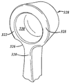
본 발명의 다른 실시예는 도 9 내지 도 11에 나타나 있고, 대체로 부재번호 300으로 지시되어 있다. 어셈블리(300)는 피스톤 부재(310)와 커넥팅 로드(320)를 포함한다. Another embodiment of the present invention is shown in Figures 9-11, generally indicated at 300. The
피스톤 부재(310)는 형성되는 방법 및 만들어지는 재료에 관하여 상술된 피스톤 부재와 유사하다. 피스톤 부재(310)는 또한 상술되고 도시되어 있는 냉각 갤러리와 본질적으로 동일하거나 동일한 방식으로 만들어진 냉각 갤러리(312)를 가진다. The
피스톤 부재(310)는 그 소켓(314)(또는 "포켓") 및 커넥팅 로드(320)가 소켓에 연결되는 방식에 관하여 상술된 피스톤 부재와 상이하다. 소켓은, 실린더 형상이면서 커넥팅 로드(320)의 소단부 상의 실린더 형상의 볼(322)에 들어맞는 개구를 가진다. The
커넥팅 로드(320)는 그 일부만이 도시되어 있는 기다란 샤프트 부재(324) 및 그 소단부에 있는 볼 부재(322)를 가진다. 볼은 도면에 나타나 있는 바와 같이 실린더 형상을 가진다.The connecting
커넥팅 로드(320)가 피스톤 부재(310)에 조립될 때, 볼 부재(322)는 측면으로부터, 즉 커넥팅 로드의 길이방향에 대해 횡단 방향으로 소켓(314)에 삽입된다. 도 9에서, 볼 부재(322)는 부분적으로만 소켓에 삽입된다. When the connecting
소켓의 하부 단부(315, 316)는 커넥팅 로드를 길이 방향 적소에 보유한다. 단부들(315, 316)은 커넥팅 로드의 넥(326)에 의해 형성된 영역 속으로 뻗어있다. The lower ends 315 and 316 of the socket retain the connecting rod in its longitudinal position. The ends 315 and 316 extend into the region defined by the
바람직하게는, 실린더 형상의 볼(322)의 2개의 측면(328)은 하나 이상의 리세스 또는 오목부(330)를 가진다. 리세스는 커넥팅 로드의 중량 내지 질량을 줄인다.Preferably, the two
본 발명이 바람직한 실시예들에 관하여 기술되어 있지만, 다음의 청구범위에 의해 기술된 바와 같이 본 발명의 전체 범위 내에 있는 본 명세서에서 변경과 수정이 행해질 수 있기 때문에 제한되어서는 안된다는 점은 이해되어야 한다.While the invention has been described with respect to preferred embodiments, it should be understood that changes and modifications may be made therein without departing from the scope of the invention as described by the following claims .
Claims (22)
상부 크라운 부재와 하부 측벽 부재를 가지는 피스톤 바디; 및
볼 타입 단부를 가지는 커넥팅 로드;
를 구비하고,
상기 상부 크라운 부재와 하부 크라운 부재는 원피스형 피스톤 바디를 형성하도록 일체로 함께 접합되고,
상기 피스톤 바디는 상기 상부 크라운 부재와 상기 하부 측벽 부재 사이에 형성된 냉각 갤러리를 가지고,
상기 하부 측벽 부재는 피스톤 보스를 가지고, 상기 보스는 커넥팅 로드의 수용을 위한 포켓을 포함하고,
상기 볼 타입 단부는 상기 포켓 내에 위치결정되는 것을 특징으로 하는 피스톤 및 커넥팅 로드 어셈블리.A piston and connecting rod assembly,
A piston body having an upper crown member and a lower sidewall member; And
A connecting rod having a ball type end;
And,
Wherein the upper crown member and the lower crown member are integrally joined together to form a one-piece piston body,
The piston body having a cooling gallery formed between the upper crown member and the lower sidewall member,
Said lower sidewall member having a piston boss, said boss comprising a pocket for receiving a connecting rod,
Wherein said ball type end is positioned within said pocket. ≪ Desc / Clms Page number 15 >
상기 냉각 갤러리는 폐쇄형 갤러리를 구비하는 것을 특징으로 하는 피스톤 및 커넥팅 로드 어셈블리.The method according to claim 1,
Wherein the cooling gallery comprises a closed gallery.
오일의 유입 및 유출을 위하여 상기 냉각 시스템 내에 복수의 개구를 더 구비하는 것을 특징으로 하는 피스톤 및 커넥팅 로드 어셈블리.3. The method of claim 2,
Further comprising a plurality of openings in said cooling system for the inflow and outflow of oil.
상기 냉각 갤러리는 개방형 갤러리를 구비하는 것을 특징으로 하는 피스톤 및 커넥팅 로드 어셈블리.The method according to claim 1,
Wherein the cooling gallery includes an open gallery.
상기 커넥팅 로드의 상기 볼 타입 단부는 2개의 대향하는 평평한 표면들, 및 2개의 대향하는 평평한 표면들 사이의 제 1 곡선 표면을 가지는 것을 특징으로 하는 피스톤 및 커넥팅 로드 어셈블리.The method according to claim 1,
The ball-type end of the connecting rod having a first curved surface between two opposing flat surfaces and two opposing flat surfaces.
상기 보스 내의 상기 포켓은 상기 제 1 곡선 표면에 대응하는 형상의 제 2 곡선 표면을 가지는 것을 특징으로 하는 피스톤 및 커넥팅 로드 어셈블리.6. The method of claim 5,
Wherein the pocket in the boss has a second curved surface of a shape corresponding to the first curved surface.
상기 볼 타입 단부는 상기 포켓의 폭과 실질적으로 동일한 폭을 가지는 것을 특징으로 하는 피스톤 및 커넥팅 로드 어셈블리.The method according to claim 1,
Said ball-type end having a width substantially equal to the width of said pocket.
상기 볼 타입 단부는 한 쌍의 평평한 표면을 가지고, 최종 조작 포지션으로부터 90°로 상기 포켓 내에 처음으로 위치결정되도록 되어 있는 것을 특징으로 하는 피스톤 및 커넥팅 로드 어셈블리.The method according to claim 1,
Wherein said ball type end has a pair of flat surfaces and is adapted to initially be positioned within said pocket by 90 degrees from a final operative position.
상기 커넥팅 로드의 상기 볼 타입 단부를 상기 포켓 내에 고정하는 것 및 상기 커넥팅 로드의 길이방향 축 둘레에서 상기 피스톤 바디의 회전을 방지하는 것을 위한 패스너 부재를 더 구비하는 것을 특징으로 하는 피스톤 및 커넥팅 로드 어셈블리.The method according to claim 1,
Further comprising a fastener member for securing said ball type end of said connecting rod within said pocket and for preventing rotation of said piston body about a longitudinal axis of said connecting rod .
상기 패스너 부재는 C-클립을 구비하고, 상기 보스 내의 상기 그루브 내에 위치결정되는 것을 특징으로 하는 피스톤 및 커넥팅 로드 어셈블리.10. The method of claim 9,
Wherein the fastener member comprises a C-clip and is positioned within the groove in the boss.
상기 피스톤 바디 내에 복수의 피스톤 링 그루브를 더 구비하는 것을 특징으로 하는 피스톤 및 커넥팅 로드.The method according to claim 1,
Further comprising a plurality of piston ring grooves in the piston body.
상기 피스톤 링 그루브들 중 적어도 하나는 상기 크라운 부재 내에 위치되어 있는 것을 특징으로 하는 피스톤 및 커넥팅 로드.The method according to claim 1,
Wherein at least one of the piston ring grooves is located within the crown member.
상기 볼 타입 단부는 실린더 형상인 것을 특징으로 하는 피스톤 및 커넥팅 로드.The method according to claim 1,
Wherein the ball type end is in the form of a cylinder.
상기 볼 타입 단부는 2개의 실질적으로 평평한 측면 표면, 및 곡선이면서 실린더 형상의 외주 외측 표면을 가지는 것을 특징으로 하는 피스톤 및 커넥팅 로드.14. The method of claim 13,
Wherein said ball type end has two substantially flat side surfaces and a curved, cylindrical outer peripheral outer surface.
상기 2개의 측면 표면들 중 적어도 하나에 적어도 하나의 리세스를 더 구비하는 것을 특징으로 하는 피스톤 및 커넥팅 로드.15. The method of claim 14,
Further comprising at least one recess on at least one of the two side surfaces. ≪ Desc / Clms Page number 13 >
각각의 상기 측면 표면에 적어도 하나의 리세스를 더 구비하는 것을 특징으로 하는 피스톤 및 커넥팅 로드.15. The method of claim 14,
Further comprising at least one recess on each of said side surfaces. ≪ Desc / Clms Page number 13 >
상기 상부 크라운 부재와 하부 크라운 부재는 원피스형 피스톤 바디를 형성하도록 일체로 함께 접합되고,
상기 피스톤 바디는 상기 상부 크라운 부재와 상기 하부 측벽 부재 사이에 형성된 냉각 갤러리를 가지고,
상기 하부 측벽 부재는 피스톤 보스를 가지고, 상기 보스는 커넥팅 로드의 수용을 위한 포켓을 포함하는 것을 특징으로 하는 피스톤.A piston comprising a piston body having an upper crown member and a lower sidewall member,
Wherein the upper crown member and the lower crown member are integrally joined together to form a one-piece piston body,
The piston body having a cooling gallery formed between the upper crown member and the lower sidewall member,
The lower sidewall member having a piston boss, the boss comprising a pocket for receiving the connecting rod.
상기 냉각 갤러리는 폐쇄형 갤러리를 구비하는 것을 특징으로 하는 피스톤.18. The method of claim 17,
Wherein the cooling gallery comprises a closed gallery.
오일의 유입 및 유출을 위하여 상기 냉각 시스템 내에 복수의 개구를 더 구비하는 것을 특징으로 하는 피스톤.19. The method of claim 18,
Further comprising a plurality of openings in said cooling system for the inflow and outflow of oil.
상기 냉각 갤러리는 개방형 갤러리를 구비하는 것을 특징으로 하는 피스톤.18. The method of claim 17,
Wherein the cooling gallery comprises an open gallery.
상기 포켓에 인접한 적어도 하나의 그루브를 더 구비하고, 상기 그루브는 커넥팅 로드를 적소에 고정하는 것 및 커넥팅 로드의 회전을 방지하는 것을 위한 패스너 부재를 수용하도록 되어 있는 것을 특징으로 하는 피스톤.18. The method of claim 17,
Further comprising at least one groove adjacent the pocket, the groove adapted to receive a fastener member for securing the connecting rod in place and preventing rotation of the connecting rod.
상기 포켓은 실린더 형상인 것을 특징으로 하는 피스톤.18. The method of claim 17,
Wherein the pockets are in the shape of a cylinder.
Applications Claiming Priority (5)
| Application Number | Priority Date | Filing Date | Title |
|---|---|---|---|
| US201361878507P | 2013-09-16 | 2013-09-16 | |
| US61/878,507 | 2013-09-16 | ||
| PCT/US2014/055813 WO2015039080A1 (en) | 2013-09-16 | 2014-09-16 | Pinless piston with gallery |
| US14/487,498 | 2014-09-16 | ||
| US14/487,498 US9303584B2 (en) | 2013-09-16 | 2014-09-16 | Pinless piston with gallery |
Publications (1)
| Publication Number | Publication Date |
|---|---|
| KR20160085746A true KR20160085746A (en) | 2016-07-18 |
Family
ID=51842749
Family Applications (1)
| Application Number | Title | Priority Date | Filing Date |
|---|---|---|---|
| KR1020167008562A KR20160085746A (en) | 2013-09-16 | 2014-09-16 | Pinless piston with gallery |
Country Status (5)
| Country | Link |
|---|---|
| US (1) | US9303584B2 (en) |
| JP (1) | JP6412139B2 (en) |
| KR (1) | KR20160085746A (en) |
| CN (1) | CN105849443B (en) |
| WO (1) | WO2015039080A1 (en) |
Cited By (1)
| Publication number | Priority date | Publication date | Assignee | Title |
|---|---|---|---|---|
| KR20180039873A (en) * | 2016-10-11 | 2018-04-19 | 현대자동차주식회사 | Piston Assembly with Improving Lubrication Performance |
Families Citing this family (8)
| Publication number | Priority date | Publication date | Assignee | Title |
|---|---|---|---|---|
| KR102074774B1 (en) * | 2012-09-27 | 2020-02-07 | 테네코 인코퍼레이티드 | Reduced compression height piston and piston assembly therewith and methods of construction thereof |
| DE102015114952A1 (en) * | 2015-09-07 | 2017-03-09 | Volkswagen Aktiengesellschaft | Combination of a piston and a connecting rod |
| DE102016221352A1 (en) * | 2016-10-28 | 2018-05-03 | Mahle International Gmbh | Method for producing a piston |
| EP3330577A1 (en) | 2016-11-30 | 2018-06-06 | ThyssenKrupp Metalúrgica Campo Limpo Ltda. | Piston - connecting rod assembly |
| DE102018211361B4 (en) * | 2018-07-10 | 2020-03-05 | Federal-Mogul Nürnberg GmbH | Pistons for an internal combustion engine |
| DE102021134517A1 (en) | 2021-12-23 | 2023-06-29 | Newgreen Ag | Pistons, connecting rods, crank mechanisms and reciprocating internal combustion engines |
| DE102021134520A1 (en) * | 2021-12-23 | 2023-06-29 | Newgreen Ag | Pistons, crank mechanism and reciprocating internal combustion engine |
| WO2024015849A1 (en) * | 2022-07-12 | 2024-01-18 | Transcend Energy Group, Llc | Piston assembly and associated components and systems |
Family Cites Families (33)
| Publication number | Priority date | Publication date | Assignee | Title |
|---|---|---|---|---|
| US1663612A (en) | 1926-04-08 | 1928-03-27 | Allan E Reed | Universal joint for pistons |
| US1763625A (en) | 1927-04-21 | 1930-06-10 | Gen Electric Co Ltd | Piston for internal-combustion engines |
| US1856107A (en) | 1928-04-10 | 1932-05-03 | Gen Electric Co Ltd | Piston for internal combustion engines |
| US1898872A (en) | 1930-02-07 | 1933-02-21 | Nestor S Evanoff | Piston and means for connecting the connecting rod thereto |
| US1899355A (en) * | 1930-05-20 | 1933-02-28 | Reid Piston Company | Piston and connecting rod |
| GB372910A (en) * | 1931-04-14 | 1932-05-19 | Eric Crisp Lewis | Improvements in or relating to pistons |
| US1995570A (en) * | 1932-11-26 | 1935-03-26 | Lewis Eric Crisp | Piston rod connection |
| US1996994A (en) * | 1932-12-24 | 1935-04-09 | Grubb Lee | Bearing |
| US2296469A (en) * | 1939-01-10 | 1942-09-22 | Paul S Mantonya | Trunk piston |
| US2297649A (en) * | 1939-12-09 | 1942-09-29 | Donaldson Piston Corp | Piston |
| US2317004A (en) | 1939-12-13 | 1943-04-20 | Wallgren August Gunn Ferdinand | Lubricating piston engine |
| US2369500A (en) | 1941-02-01 | 1945-02-13 | Sulzer Ag | Piston cooling |
| US2819936A (en) * | 1954-08-03 | 1958-01-14 | Fried Krupp Motoren Und Kraftw | Piston, especially for internal combustion engines |
| US3765307A (en) * | 1972-02-07 | 1973-10-16 | J Neel | Pinless piston assembly |
| US4372179A (en) * | 1978-01-25 | 1983-02-08 | Steyr-Daimler-Puch Aktiengesellschaft | Reciprocating-piston drive mechanism |
| FR2575227B1 (en) | 1984-12-20 | 1988-12-23 | Semt | PISTON WITH LIGHT STRUCTURE, PARTICULARLY FOR AN INTERNAL COMBUSTION ENGINE |
| US4635596A (en) * | 1985-08-12 | 1987-01-13 | Kawasaki Jukogyo Kabushiki Kaisha | Assembly of piston and connecting rod in internal-combustion engine |
| JPH01124389U (en) * | 1988-02-18 | 1989-08-24 | ||
| US4858566A (en) | 1988-03-16 | 1989-08-22 | Paul Marius A | Axially symmetrical piston for reciprocal engines |
| ATE115239T1 (en) | 1990-03-30 | 1994-12-15 | Isuzu Motors Ltd | CONNECTION STRUCTURE OF A PISTON AND CONNECTING ROD. |
| WO1992011453A1 (en) * | 1990-12-17 | 1992-07-09 | Tsentralny Nauchno-Issledovatelsky Avtomobilny I Avtomotorny Institut | Ball-and-socket joint connection |
| US5165375A (en) * | 1992-01-03 | 1992-11-24 | Jacobs Brake Technology Corporation | Master piston for a compression release engine retarder |
| DE19519730A1 (en) * | 1995-06-02 | 1996-12-05 | Kolbenschmidt Ag | Piston-connecting rod arrangement for internal combustion engines |
| US5669285A (en) | 1996-02-07 | 1997-09-23 | Cummins Engine Company, Inc. | Spherical joint connecting rod holder rings |
| US5685267A (en) * | 1996-02-07 | 1997-11-11 | Cummins Engine Company, Inc. | Spherical joint connecting rod |
| GB9908844D0 (en) | 1999-04-19 | 1999-06-16 | Seneca Tech Ltd | Piston-connecting rod retention |
| GB9909033D0 (en) | 1999-04-19 | 1999-06-16 | Seneca Tech Ltd | Piston coolant path |
| DE10356200B4 (en) * | 2003-12-02 | 2006-08-03 | Man B & W Diesel Ag | Engine of an internal combustion engine with piston and connecting rod |
| US7290518B2 (en) | 2005-03-28 | 2007-11-06 | Honda Motor Co., Ltd. | Piston-connecting rod spherical coupling structure |
| JP2007211694A (en) | 2006-02-09 | 2007-08-23 | Honda Motor Co Ltd | Piston for internal combustion engine |
| US8100048B2 (en) * | 2007-10-02 | 2012-01-24 | Federal-Mogul Corporation | Pinless piston and connecting rod assembly |
| CN102388213B (en) * | 2009-04-10 | 2014-01-08 | 费德罗-莫格尔公司 | Piston with crown cooling jet |
| FI20095732A (en) * | 2009-06-29 | 2010-12-30 | Waertsilae Finland Oy | METHOD FOR ROTARY PISTON INSTALLATION AND BEARING |
-
2014
- 2014-09-16 KR KR1020167008562A patent/KR20160085746A/en not_active Application Discontinuation
- 2014-09-16 US US14/487,498 patent/US9303584B2/en active Active
- 2014-09-16 JP JP2016542868A patent/JP6412139B2/en not_active Expired - Fee Related
- 2014-09-16 WO PCT/US2014/055813 patent/WO2015039080A1/en active Application Filing
- 2014-09-16 CN CN201480056098.0A patent/CN105849443B/en not_active Expired - Fee Related
Cited By (1)
| Publication number | Priority date | Publication date | Assignee | Title |
|---|---|---|---|---|
| KR20180039873A (en) * | 2016-10-11 | 2018-04-19 | 현대자동차주식회사 | Piston Assembly with Improving Lubrication Performance |
Also Published As
| Publication number | Publication date |
|---|---|
| JP6412139B2 (en) | 2018-10-24 |
| US9303584B2 (en) | 2016-04-05 |
| WO2015039080A9 (en) | 2016-01-14 |
| WO2015039080A1 (en) | 2015-03-19 |
| CN105849443A (en) | 2016-08-10 |
| CN105849443B (en) | 2018-01-30 |
| JP2016538510A (en) | 2016-12-08 |
| US20150075456A1 (en) | 2015-03-19 |
Similar Documents
| Publication | Publication Date | Title |
|---|---|---|
| KR20160085746A (en) | Pinless piston with gallery | |
| JP5912360B2 (en) | Locking joint assembly | |
| US10450999B2 (en) | Reduced compression height dual gallery piston, piston assembly therewith and methods of construction thereof | |
| CN102422005B (en) | Piston having a central cooling gallery with a contoured flange | |
| KR100955741B1 (en) | A piston for diesel engines | |
| JP5481684B2 (en) | Connecting rod with piston assembly and contoured wrist pin hole therefor | |
| KR20040039364A (en) | Closed gallery piston having pin bore lubrication | |
| US7845269B2 (en) | Piston with pin bore lubrication features | |
| US7954421B2 (en) | Lightweight piston | |
| US20090084260A1 (en) | Pinless piston and connecting rod assembly | |
| KR102008165B1 (en) | Piston pin for heat dissipation | |
| KR20170130474A (en) | Piston with solid, light and low compression height and method of making same | |
| US3877350A (en) | Piston and connecting rod assembly | |
| US7451737B2 (en) | Powertrain of an internal combustion engine with piston and connecting rod | |
| US9470311B2 (en) | Lightweight engine power cell assembly | |
| EP3047180B1 (en) | Pinless piston with gallery | |
| US20090101004A1 (en) | Two part piston for an internal combustion engine | |
| KR20180134938A (en) | Piston having asymmetric upper combustion surface and method of manufacturing the same | |
| US9447877B2 (en) | Mounting arrangement for a piston-connecting rod assembly in a refrigeration compressor | |
| WO2018099858A1 (en) | Piston - connecting rod assembly | |
| EP0654595B1 (en) | Piston for alternating volumetric engines | |
| JP2013503300A (en) | Monoblock piston with low friction skirt | |
| WO2019191751A1 (en) | Lubrication feature for pin of two stroke piston assembly | |
| JPH0131027B2 (en) |
Legal Events
| Date | Code | Title | Description |
|---|---|---|---|
| A201 | Request for examination | ||
| E902 | Notification of reason for refusal | ||
| E601 | Decision to refuse application |