KR20160059984A - Electric compressor - Google Patents
Electric compressor Download PDFInfo
- Publication number
- KR20160059984A KR20160059984A KR1020150161948A KR20150161948A KR20160059984A KR 20160059984 A KR20160059984 A KR 20160059984A KR 1020150161948 A KR1020150161948 A KR 1020150161948A KR 20150161948 A KR20150161948 A KR 20150161948A KR 20160059984 A KR20160059984 A KR 20160059984A
- Authority
- KR
- South Korea
- Prior art keywords
- motor
- cover
- housing
- main body
- housing main
- Prior art date
Links
Images


Classifications
-
- H—ELECTRICITY
- H02—GENERATION; CONVERSION OR DISTRIBUTION OF ELECTRIC POWER
- H02K—DYNAMO-ELECTRIC MACHINES
- H02K11/00—Structural association of dynamo-electric machines with electric components or with devices for shielding, monitoring or protection
- H02K11/30—Structural association with control circuits or drive circuits
- H02K11/33—Drive circuits, e.g. power electronics
-
- H—ELECTRICITY
- H01—ELECTRIC ELEMENTS
- H01F—MAGNETS; INDUCTANCES; TRANSFORMERS; SELECTION OF MATERIALS FOR THEIR MAGNETIC PROPERTIES
- H01F27/00—Details of transformers or inductances, in general
- H01F27/34—Special means for preventing or reducing unwanted electric or magnetic effects, e.g. no-load losses, reactive currents, harmonics, oscillations, leakage fields
- H01F27/36—Electric or magnetic shields or screens
- H01F27/363—Electric or magnetic shields or screens made of electrically conductive material
-
- F—MECHANICAL ENGINEERING; LIGHTING; HEATING; WEAPONS; BLASTING
- F04—POSITIVE - DISPLACEMENT MACHINES FOR LIQUIDS; PUMPS FOR LIQUIDS OR ELASTIC FLUIDS
- F04B—POSITIVE-DISPLACEMENT MACHINES FOR LIQUIDS; PUMPS
- F04B35/00—Piston pumps specially adapted for elastic fluids and characterised by the driving means to their working members, or by combination with, or adaptation to, specific driving engines or motors, not otherwise provided for
- F04B35/04—Piston pumps specially adapted for elastic fluids and characterised by the driving means to their working members, or by combination with, or adaptation to, specific driving engines or motors, not otherwise provided for the means being electric
-
- F—MECHANICAL ENGINEERING; LIGHTING; HEATING; WEAPONS; BLASTING
- F04—POSITIVE - DISPLACEMENT MACHINES FOR LIQUIDS; PUMPS FOR LIQUIDS OR ELASTIC FLUIDS
- F04B—POSITIVE-DISPLACEMENT MACHINES FOR LIQUIDS; PUMPS
- F04B39/00—Component parts, details, or accessories, of pumps or pumping systems specially adapted for elastic fluids, not otherwise provided for in, or of interest apart from, groups F04B25/00 - F04B37/00
- F04B39/12—Casings; Cylinders; Cylinder heads; Fluid connections
- F04B39/121—Casings
-
- H—ELECTRICITY
- H01—ELECTRIC ELEMENTS
- H01F—MAGNETS; INDUCTANCES; TRANSFORMERS; SELECTION OF MATERIALS FOR THEIR MAGNETIC PROPERTIES
- H01F27/00—Details of transformers or inductances, in general
- H01F27/34—Special means for preventing or reducing unwanted electric or magnetic effects, e.g. no-load losses, reactive currents, harmonics, oscillations, leakage fields
- H01F27/36—Electric or magnetic shields or screens
-
- H—ELECTRICITY
- H02—GENERATION; CONVERSION OR DISTRIBUTION OF ELECTRIC POWER
- H02K—DYNAMO-ELECTRIC MACHINES
- H02K11/00—Structural association of dynamo-electric machines with electric components or with devices for shielding, monitoring or protection
- H02K11/02—Structural association of dynamo-electric machines with electric components or with devices for shielding, monitoring or protection for suppression of electromagnetic interference
-
- H—ELECTRICITY
- H05—ELECTRIC TECHNIQUES NOT OTHERWISE PROVIDED FOR
- H05K—PRINTED CIRCUITS; CASINGS OR CONSTRUCTIONAL DETAILS OF ELECTRIC APPARATUS; MANUFACTURE OF ASSEMBLAGES OF ELECTRICAL COMPONENTS
- H05K7/00—Constructional details common to different types of electric apparatus
- H05K7/14—Mounting supporting structure in casing or on frame or rack
- H05K7/1422—Printed circuit boards receptacles, e.g. stacked structures, electronic circuit modules or box like frames
- H05K7/1427—Housings
- H05K7/1432—Housings specially adapted for power drive units or power converters
-
- H—ELECTRICITY
- H05—ELECTRIC TECHNIQUES NOT OTHERWISE PROVIDED FOR
- H05K—PRINTED CIRCUITS; CASINGS OR CONSTRUCTIONAL DETAILS OF ELECTRIC APPARATUS; MANUFACTURE OF ASSEMBLAGES OF ELECTRICAL COMPONENTS
- H05K9/00—Screening of apparatus or components against electric or magnetic fields
- H05K9/0007—Casings
-
- H—ELECTRICITY
- H02—GENERATION; CONVERSION OR DISTRIBUTION OF ELECTRIC POWER
- H02K—DYNAMO-ELECTRIC MACHINES
- H02K5/00—Casings; Enclosures; Supports
- H02K5/04—Casings or enclosures characterised by the shape, form or construction thereof
- H02K5/22—Auxiliary parts of casings not covered by groups H02K5/06-H02K5/20, e.g. shaped to form connection boxes or terminal boxes
- H02K5/225—Terminal boxes or connection arrangements
-
- H—ELECTRICITY
- H02—GENERATION; CONVERSION OR DISTRIBUTION OF ELECTRIC POWER
- H02M—APPARATUS FOR CONVERSION BETWEEN AC AND AC, BETWEEN AC AND DC, OR BETWEEN DC AND DC, AND FOR USE WITH MAINS OR SIMILAR POWER SUPPLY SYSTEMS; CONVERSION OF DC OR AC INPUT POWER INTO SURGE OUTPUT POWER; CONTROL OR REGULATION THEREOF
- H02M1/00—Details of apparatus for conversion
- H02M1/44—Circuits or arrangements for compensating for electromagnetic interference in converters or inverters
-
- H—ELECTRICITY
- H02—GENERATION; CONVERSION OR DISTRIBUTION OF ELECTRIC POWER
- H02M—APPARATUS FOR CONVERSION BETWEEN AC AND AC, BETWEEN AC AND DC, OR BETWEEN DC AND DC, AND FOR USE WITH MAINS OR SIMILAR POWER SUPPLY SYSTEMS; CONVERSION OF DC OR AC INPUT POWER INTO SURGE OUTPUT POWER; CONTROL OR REGULATION THEREOF
- H02M7/00—Conversion of ac power input into dc power output; Conversion of dc power input into ac power output
- H02M7/003—Constructional details, e.g. physical layout, assembly, wiring or busbar connections
Abstract
Description
본 발명은 전동 압축기에 관한 것이다.The present invention relates to an electric compressor.
일본 비심사 특허 출원 공개 공보 No. 2010-209788 은 차량 상에 장착되고 하우징, 모터 부품, 압축 부품, 및 인버터 장치를 포함하는 전동 압축기를 개시한다. 압축 부품은 냉매 가스를 압축하기 위해 모터 부품에 의해 구동된다. 인버터 장치는 모터 부품을 구동한다. 모터 부품 및 압축 부품은 하우징에 배치된다. 수용 챔버는 인버터 장치를 그 안에 수용하기 위해 하우징의 외부 주변 상에 형성된다.Japanese Unexamined Patent Application Laid-Open Publication No. 2010-209788 discloses a motor-driven compressor mounted on a vehicle and including a housing, a motor component, a compression component, and an inverter device. The compression component is driven by the motor component to compress the refrigerant gas. The inverter device drives the motor parts. The motor component and the compression component are disposed in the housing. The receiving chamber is formed on the outer periphery of the housing to receive the inverter device therein.
인버터 장치는 전원으로부터의 직류 전류를 교류 전류로 변환하면서 모터 부품에 전력을 공급한다. 인버터 장치는 인버터 회로, 인버터 장치에 제공된 전도체들, 통신 케이블들, 및 전자기 노이즈 제거 부재를 포함한다. 내부 전도체들은 수용 챔버에서 인버터 회로 및 전원에 전기적으로 연결된다. 통신 케이블들은 인버터 회로에 그리고 또한 차량의 제어 장치와 연결된다. 전자기 노이즈 제거 부재는 통신 케이블들 상에 제공된다. 노이즈 제거 부재의 예들은 페라이트 코어를 포함한다.The inverter device converts the direct current from the power source into an alternating current and supplies power to the motor part. The inverter device includes an inverter circuit, conductors provided to the inverter device, communication cables, and an electromagnetic noise removing member. The inner conductors are electrically connected to the inverter circuit and the power source in the receiving chamber. The communication cables are connected to the inverter circuit and also to the controls of the vehicle. An electromagnetic noise removing member is provided on the communication cables. Examples of noise canceling members include a ferrite core.
상기 공개 공보의 전동 압축기에 따르면, 통신 케이블들 상에 제공된 노이즈 제거 부재는 통신 케이블들을 통해 수용 챔버 내로 방사되는 전자기 노이즈를 방지하거나 또는 감소시킨다.According to the motor-operated compressors of the above publications, the noise canceling member provided on the communication cables prevents or reduces electromagnetic noise radiated into the accommodating chamber through the communication cables.
차량 상에 장착된 전동 압축기에서, 많은 전류가 내부 전도체들을 통해 전원으로부터 인버터 회로로 공급되어, 내부 전도체들로부터 방사되는 전자기 노이즈는 현저하게 커지고 따라서 차량의 다른 장치들에서 발생된 전자기 노이즈도 커진다.In a motor-driven compressor mounted on a vehicle, a large amount of current is supplied from an electric power source to an inverter circuit through internal conductors, so that the electromagnetic noise radiated from the internal conductors becomes remarkably large, and the electromagnetic noise generated in other devices of the vehicle also becomes large.
상기 인용된 공개 공보의 종래의 전동 압축기에서, 전자기 노이즈로부터 통신 케이블들을 보호하기 위한 조치들은 노이즈 제거 부재를 제공함으로써 취해지지만, 내부 전도체들에 대해서는 어떠한 조치들도 취해지지 않는다. 그러므로, 내부 전도체들로부터 방사되는 전자기 노이즈는 차량에서의 다른 장치들에 영향을 줄 수 있거나 또는 차량에서의 그러한 다른 장치들로부터 전자기 노이즈는 인버터 회로를 정지하게 만들 수 있다.In the conventional motor-operated compressors of the above cited publications, measures for protecting the communication cables from electromagnetic noise are taken by providing a noise canceling member, but no action is taken on internal conductors. Therefore, electromagnetic noise radiated from internal conductors can affect other devices in the vehicle, or electromagnetic noise from such other devices in the vehicle can cause the inverter circuit to stop.
전자기 노이즈를 충분하게 제거하도록, 큰 사이즈의 노이즈 제거 장치가 요구된다. 전동 압축기에서 큰 노이즈 제거 부재를 제공하도록, 하우징의 사이즈는 증가되어 큰 수용 공간을 제공할 필요가 있고, 이는 전동 압축기 자체의 사이즈를 증가시키고 차량 상에 전동 압축기의 용이한 장착을 방해한다.A large-size noise removing device is required to sufficiently remove electromagnetic noise. In order to provide a large noise removing member in the motor-driven compressor, the size of the housing needs to be increased to provide a large accommodating space, which increases the size of the motor-driven compressor itself and hinders easy mounting of the motor-driven compressor on the vehicle.
상기 설명된 환경들을 감안하여 행해진 본 발명은 용이하게 장착될 수 있고 적어도 내부 전도체들로부터 방사되는 전자기 노이즈를 적당히 흡수할 수 있는 전동 압축기에 관한 것이다.The present invention made in view of the above-described circumstances relates to a motor-driven compressor which can be easily mounted and which can appropriately absorb electromagnetic noise emitted from at least internal conductors.
본 발명의 양상에 따르면, 하우징, 모터 부품, 모터 부품에 의해 구동되고 냉매 가스를 압축하는 압축 부품, 및 모터 부품을 구동하는 인버터 장치를 포함하는 전동 압축기가 제공된다. 하우징은 모터 부품 및 압축 부품이 배치되는 하우징 본체, 및 하우징 본체에 고정됨으로써 인버터 장치를 하우징 본체에 수용하기 위해 하우징 본체와의 사이에서 수용 챔버를 형성하는 커버를 포함한다. 인버터 장치는 인버터 회로, 두개의 내부 전도체들로서, 그들의 일단부들에서 인버터 회로에 전기적으로 연결되고 그들의 타단부들에서 전원과 전기적으로 연결 가능하고, 상기 전원은 수용 챔버 외측에 제공되어 전원으로부터 인버터 회로로 직류 전류를 공급하는, 상기 두개의 내부 전도체들, 및 적어도 두개의 내부 전도체들로부터 방사되는 전자기 노이즈를 흡수하는 전자기 노이즈 제거 부재를 포함한다. 커버는 하우징 본체로부터 이간된 바닥벽 및 바닥 벽으로부터 하우징 본체를 향해 연장되는 주변 벽을 포함한다. 바닥 벽은 하우징 본체로부터 이간되어 돌출됨으로써 내부에 수용 공간을 형성하는 돌출 부분을 갖는다. 두개의 내부 전도체들의 각각은 그 일단부에서 인버터 회로에 연결되거나 또는 그 일단부에서 전원에 연결 가능한 연장부 및 상기 연장부의 타단부에 연결된 굴곡부를 포함한다. 굴곡부는 연장부보다 하우징 본체로부터 더 떨어져 배치되고 굴곡부의 적어도 일부는 전자기 노이즈 제거 부재로 덮혀진다. 전자기 노이즈 제거 부재의 적어도 일부는 수용 공간에 배치된다.According to an aspect of the present invention, there is provided an electric compressor including a housing, a motor component, a compression component driven by the motor component and compressing the refrigerant gas, and an inverter device for driving the motor component. The housing includes a housing main body in which the motor parts and the compression parts are disposed, and a cover fixed to the housing main body to form an accommodating chamber between the housing main body and the inverter main body for accommodating the inverter device in the housing main body. The inverter device comprises an inverter circuit, two internal conductors, electrically connected to the inverter circuit at one end thereof, and electrically connectable to a power source at their other ends, the power source being provided outside the receiving chamber, The two internal conductors supplying the direct current, and the electromagnetic noise removing member absorbing the electromagnetic noise radiated from the at least two internal conductors. The cover includes a bottom wall spaced apart from the housing body and a peripheral wall extending from the bottom wall toward the housing body. The bottom wall has a protruding portion which protrudes from the housing main body to form a receiving space therein. Each of the two internal conductors includes an extension connected at one end thereof to the inverter circuit or at one end thereof for connection to a power supply, and a bent portion connected to the other end of the extension. The bend is located further away from the housing body than the extension and at least a portion of the bend is covered with an electromagnetic noise removal member. At least a part of the electromagnetic noise removing member is disposed in the receiving space.
본 발명의 다른 양상들 및 이점들은 본 발명의 원리들을 예로써 예시한 첨부된 도면들과 함께 취해진 다음의 설명으로부터 명백해질 것이다.Other aspects and advantages of the present invention will become apparent from the following description taken in conjunction with the accompanying drawings, which illustrate, by way of example, the principles of the invention.
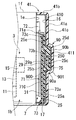
도 1 는 전동 압축기의 일부가 단면도로 도시된 본 발명의 제 1 실시형태에 따른 전동 압축기를 도시하고;
도 2 는 본 발명의 제 1 실시형태에 따른 전동 압축기의 급전 어셈블리의 확대된 단면도이고;
도 3 은 도 1 의 라인 III-III 을 따라 취해진 제 1 실시형태에 따른 전동 압축기의 확대된 단면도이고;
도 4 는 제 1 실시형태와의 비교를 위한 실시형태로서 전동 압축기를 도시하는 부분적인 단면도이고;
도 5 는 본 발명의 제 2 실시형태에 따른 전동 압축기의 부분적인 단면도이고;
도 6 은 도 5 의 라인 VI-VI 을 따라 취해진 제 2 실시형태에 따른 전동 압축기의 확대된 단면도이고;
도 7 은 본 발명의 제 3 실시형태에 따른 전동 압축기의 부분적인 단면도이고;
도 8 은 도 7 의 라인 VIII-VIII 을 따라 취해진 제 3 실시형태에 따른 전동 압축기의 확대된 단면도이고;
도 9 는 본 발명의 제 4 실시형태에 따른 전동 압축기의 부분적인 단면도이고;
도 10 은 제 4 실시형태에 따른 전동 압축기의 커버의 또 다른 실시예의 단면도이고;
도 11 은 제 4 실시형태에 따른 전동 압축기의 커버의 추가의 또 다른 실시예의 단면도이고;
도 12 는 본 발명의 제 5 실시형태에 따른 전동 압축기의 부분적인 단면도이다.1 shows a motor-driven compressor according to a first embodiment of the present invention, in which a part of the motor-driven compressor is shown in a sectional view;
2 is an enlarged cross-sectional view of a power supply assembly of a motor-driven compressor according to a first embodiment of the present invention;
3 is an enlarged cross-sectional view of a motor-driven compressor according to a first embodiment taken along line III-III of FIG. 1;
4 is a partial sectional view showing an electric compressor as an embodiment for comparison with the first embodiment;
5 is a partial sectional view of a motor-driven compressor according to a second embodiment of the present invention;
6 is an enlarged cross-sectional view of a motor-driven compressor according to a second embodiment taken along line VI-VI of Fig. 5; Fig.
7 is a partial cross-sectional view of a motor-driven compressor according to a third embodiment of the present invention;
8 is an enlarged cross-sectional view of a motor-driven compressor according to a third embodiment taken along line VIII-VIII in FIG. 7;
9 is a partial sectional view of a motor-driven compressor according to a fourth embodiment of the present invention;
10 is a sectional view of still another embodiment of the cover of the motor-driven compressor according to the fourth embodiment;
11 is a sectional view of still another further embodiment of the cover of the motor-driven compressor according to the fourth embodiment;
12 is a partial sectional view of an electric compressor according to a fifth embodiment of the present invention.
다음은 첨부된 도면들을 참조하여 본 발명의 제 1 실시형태 내지 제 5 실시형태를 설명할 것이다. 실시형태들의 전동 압축기들은 차량 상에 장착되고 차량의 공조 장치의 냉동 회로에 통합되는 형태이다.The following will describe first to fifth embodiments of the present invention with reference to the accompanying drawings. The electric compressors of the embodiments are mounted on the vehicle and integrated into the refrigeration circuit of the air conditioning system of the vehicle.
제 1 실시형태First Embodiment
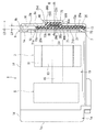
도 1 을 참조하면, 하우징 어셈블리 (1), 모터 부품 (3), 압축 부품 (5), 및 인버터 장치 (7) 를 포함하는 본 발명의 제 1 실시형태에 따른 전동 압축기가 도시된다. 하우징 어셈블리 (1) 는 제 1 하우징 (1A), 제 2 하우징 (1B), 및 커버 (9) 를 포함한다. 제 1 하우징 (1A) 및 제 2 하우징 (1B) 은 본 발명의 하우징 본체를 형성한다.1, there is shown a motor-driven compressor according to a first embodiment of the present invention including a
모터 부품 (3) 은 스테이터 (11), 로터 (13), 및 구동 샤프트 (15) 를 포함한다. 스테이터 (11) 는 제 2 하우징 (1B) 의 내부 주변 표면에 고정되고 코일 (도시생략) 을 갖는다. 로터 (13) 는 스테이터 (11) 의 방사상 내향에 배치되고 구동 샤프트 (15) 상에서 그와 함께 회전을 위해 고정되게 장착된다.The
압축 부품 (5) 은 제 2 하우징 (1A) 의 내부 주변 표면에 고정된 고정형 스크롤 및 상기 고정형 스크롤을 마주보도록 배치되고 구동 샤프트 (15) 의 회전과 함께 궤도 운동을 행하는 가동 스크롤을 포함하는 널리 공지된 스크롤 타입이다. 고정형 스크롤 및 가동 스크롤은 서로 맞물려서 압축 챔버를 그 사이에서 형성한다. 토출 챔버는 고정형 스크롤과 제 1 하우징 (1A) 사이에 형성된다. 고정형 스크롤, 가동 스크롤, 압축 챔버, 및 토출 챔버는 도 1 에서 도시되지 않는다는 것에 주목해야 된다.The compression component 5 includes a fixed scroll fixed to the inner peripheral surface of the second housing 1A and a movable scroll disposed to face the fixed scroll and orbiting together with the rotation of the
제 1 하우징 (1A) 은 구동 샤프트 (15) 의 축방향에 수직하게 연장되는 바닥 벽 (1C) 및 구동 샤프트 (15) 의 축방향으로 바닥 벽 (1C) 으로부터 연장되는 주변 벽 (1D) 을 포함한다. 바닥 벽 (1C) 및 주변 벽 (1D) 은 폐쇄된 단부 및 상기 바닥 벽 (1C) 의 대향된 측 상에서 개구를 갖는 원통을 형성한다. 바닥 벽 (1C) 은 토출 챔버와, 전동 압축기의 외측에 제공된 응측기 (도시 생략) 사이에 유체 연통을 제공하는 토출 구멍 (도시생략) 을 그를 통해 갖는다.The first housing 1A includes a bottom wall 1C extending perpendicular to the axial direction of the
제 2 하우징 (1B) 은 바닥 벽 (1E), 및 구동 샤프트 (15) 의 축방향으로 상기 바닥 벽 (1E) 으로부터 연장되는 주변 벽 (1F) 을 포함한다. 바닥 벽 (1E) 및 주변 벽 (1F) 은 폐쇄된 단부 및 상기 바닥 벽 (1E) 에 대향하는 측 상에 개구를 갖는 원통을 형성한다. 바닥 벽 (1E) 에 대향하는 제 2 하우징 (1B) 의 개방된 단부에 대해, 제 1 하우징 (1A) 이 그 개방된 단부에서 고정된다. 제 2 하우징 (1B) 의 주변 벽 (1F) 은 냉동 회로에서 외부 증발기와 제 2 하우징 (1B) 사이에서 유체 연통을 제공하는 흡입 구멍 (도시생략) 을 그를 통해 갖는다.The second housing 1B includes a bottom wall 1E and a peripheral wall 1F extending from the bottom wall 1E in the axial direction of the
커버 (9) 는 폐쇄된 단부를 구비한 원통 형상을 갖는다. 보다 구체적으로, 커버 (9) 는 제 2 하우징 (1B) 으로부터 이간된 바닥 벽 (9A) 및 상기 바닥 벽 (9A) 으로부터 제 2 하우징 (1B) 을 향해 연장되는 주변 벽 (9B) 을 포함한다. 커버 (9) 는 예를 들면 금속으로 제조되고, 제 2 하우징 (1B) 의 바닥 벽 (1E) 에 대해 그 주변 벽 (9B) 의 단부에 고정된다. 커버 (9) 및 제 2 하우징 (1B) 의 바닥 벽 (1E) 은 인버터 장치 (7) 를 그 안에 수용하기 위한 수용 챔버 (16) 를 형성한다. 급전 포트 (17) 는 커버 (9) 의 주변 벽 (9B) 을 통해 형성된다. 급전 포트 (17) 의 개구의 위치 및 배향은 선택적으로 구성될 수 있다.The
커버 (9) 의 바닥 벽 (9A) 은 제 1 및 제 2 하우징들 (1A 및 1B) 로부터 이간되어 돌출된 돌출 부분 (90) 을 갖는다. 구체적으로, 돌출 부분 (90) 은 수용 챔버 (16) 가 확장됨으로써 커버 (9) 에서 수용 공간 (75) 을 형성하도록 돌출형으로 형성된다. 보다 구체적으로, 제 1 실시형태에 따르면 커버 (9) 의 바닥 벽 (9A) 은 평탄 부분 (9C), 평탄 부분 (9C) 에 평행하게 형성된 덮개 부분 (90B), 및 평탄 부분 (9C) 및 덮개 부분 (90B) 과 일체로 형성되고 평탄 부분 (9C) 및 덮개 부분 (90B) 을 연결하는 연결 부분 (90A) 을 포함한다. 따라서, 돌출 부분 (90) 은 연결 부분 (90A) 및 덮개 부분 (90B) 에 의해 형성된다. 따라서, 덮개 부분 (90B) 은 연결 부분 (90A) 에 의해 형성된 개방된 단부를 폐쇄한다. 그러한 구성을 갖는 돌출 부분 (90) 은 커버 (9) 의 바닥 벽 (9A) 에 용이하게 형성될 수 있다.The bottom wall 9A of the
제 1 실시형태에 따른 전동 압축기에서, 돌출 부분 (90) 은 돌출 부분 (90) 에 상응하는 오목부를 형성하도록 단일한 금속 시트를 굽힘으로써 형성된다. 평탄 부분 (9C), 연결 부분 (90A), 및 덮개 부분 (90B) 은 별개로 제공되고 임의의 수단에 의해 함께 접합되어 커버 (9) 의 돌출 부분 (90) 을 형성할 수 있다. 대안적으로, 돌출 부분 (90) 은 연결 부분 (90A) 및 덮개 부분 (90B) 뿐만 아니라 임의의 다른 부재들을 포함함으로써 형성될 수 있다.In the motor-driven compressor according to the first embodiment, the protruding
인버터 장치 (7) 는 인버터 회로 (71) 및 외부 전원으로부터 상기 인버터 장치 (7) 로 전력을 공급하는 급전 어셈블리 (73) 를 포함한다. 인버터 회로 (71) 는 제 2 하우징 (1B) 의 바닥 벽 (1E) 에 부착되고 인버터 회로 (71) 가 바닥 벽 (1E) 에 부착된 상태로 수용 챔버 (16) 에 수용된다. 인버터 회로 (71) 는 회로 기판 (710) 및 상기 회로 기판 (710) 상에 배열된 복수의 반도체들 (도시생략) 을 포함하고 급전 어셈블리 (73) 를 통해 공급된 전원 (도시생략) 의 직류 전류를 교류 전류로 변환한다. 인버터 회로 (71) 에 의해 변환된 최종 교류 전류는 리드 와이어 (72) 등을 통해 모터 부품 (3) 의 스테이터 (11) 에 제공된 코일 (도시생략) 로 공급된다. 커넥터 (71A) 는 인버터 회로 (71) 에 제공되어 인버터 회로 (71) 를 급전 어셈블리 (73) 에 연결한다. 인버터 회로 (71) 는 상이한 방식으로 급전 어셈블리 (73) 에 연결될 수 있다. 예를 들면, 인버터 회로 (71) 및 급전 어셈블리 (73) 는 서로 직접적으로 연결될 수 있다.The
급전 어셈블리 (73) 는 본 발명의 절연 부재로서 수지 절연기 (31) 와 제 1 및 제 2 버스 바아들 (25 및 27), 및 페라이트 코어 (29) 를 일체화함으로써 형성된다. 제 1 및 제 2 버스 바아들 (25 및 27) 은 본 발명의 두개의 내부 전도체들에 상응한다. 페라이트 코어 (29) 는 본 발명의 전자기 노이즈 제거 부재에 상응한다.The
도 2 및 도 3 에 도시된 바와 같이, 제 1 및 제 2 버스 바아들 (25 및 27) 은 세장형의 평탄 플레이트들로 형성된다. 도 2 에 도시된 바와 같이, 제 1 버스 바아 (25) 및 제 2 버스 바아 (27) 는 서로 평행하게 배치되고 커버 (9) 의 평탄 부분 (9C) 을 따라 연장된다. 제 1 및 제 2 버스 바아들 (25 및 27) 의 형상은 평탄 플레이트에 제한되지 않지만, 제 1 및 제 2 버스 바아들 (25 및 27) 의 단면은 원형일 수 있다. 제 1 및 제 2 버스 바아들 (25 및 27) 이외의 임의의 다른 부재들이 두개의 내부 전도체들로서 사용될 수 있다.As shown in Figures 2 and 3, the first and second bus bars 25 and 27 are formed of elongated flat plates. As shown in FIG. 2, the
도 1 및 도 2 에 도시된 바와 같이, 제 1 및 제 2 버스 바아들 (25 및 27) 은 각각 굴곡부들 (250 및 270) 을 각각 갖는다. 구체적으로, 제 1 버스 바아 (25) 는 제 1 평탄 부분 (25A), 연결 부분 (25B), 제 2 평탄 부분 (25C), 슬로프형 부분 (25D), 및 제 3 평탄 부분 (25E) 을 포함하고, 각각은 대향하는 단부들을 갖는다.As shown in Figures 1 and 2, the first and second bus bars 25 and 27 each have bends 250 and 270, respectively. Specifically, the
제 1 평탄 부분 (25A) 의 일단부는 리드 와이어 (도시생략) 를 통해 도 1 에서 수용 챔버 (16) 의 외측에 제공된 전원 (도시생략) 에 연결되고 제 3 평탄 부분 (25E) 의 일단부는 커넥터 (71A) 를 통해 인버터 회로 (71) 에 연결된다. 제 3 평탄 부분 (25E) 의 일단부는 임의의 다른 전도성 부재를 통해 인버터 회로 (71) 에 연결될 수 있다는 것에 주목해야 한다. 따라서 제 1 평탄 부분 (25A) 의 일단부가 인버터 회로 (71) 에 연결되고 제 3 평탄 부분 (25E) 의 일단부가 리드 와이어를 통해 전원에 연결되도록 구성될 수 있다.One end of the first flat portion 25A is connected to a power source (not shown) provided outside the
제 2 평탄 부분 (25C) 은 제 1 및 제 3 평탄 부분들 (25A 및 25E) 이 동일한 제 1 및 제 2 하우징들 (1A 및 1B) 로부터 이간된 거리보다 제 1 및 제 2 하우징들 (1A 및 1B) 로부터 더 먼 거리로 이간된다. 제 2 평탄 부분 (25C) 의 일단부는 연결 부분 (25B) 을 통해 전원에 연결되지 않는 제 1 평탄 부분 (25A) 의 타단부에 연결된다. 제 2 평탄 부분 (25C) 의 타단부는 슬로프형 부분 (25D) 을 통해 제 3 평탄 부분 (25E) 의 타단부에 연결된다.The second flat portion 25C is formed so that the first and third flat portions 25A and 25E are spaced apart from the same distance from the first and second housings 1A and 1B by the first and second housings 1A and & RTI ID = 0.0 > 1B. ≪ / RTI > One end of the second flat portion 25C is connected to the other end of the first flat portion 25A which is not connected to the power source through the connecting portion 25B. The other end of the second flat portion 25C is connected to the other end of the third flat portion 25E through the slope portion 25D.
도 2 에 도시된 바와 같이, 제 1 버스 바아 (25) 의 굴곡부 (250) 는 연결 부분 (25B) 및 제 2 평탄 부분 (25C) 을 구비하는 제 1 굴곡 부분 (250A) 및 제 2 평탄 부분 (25C) 및 슬로프형 부분 (25D) 을 구비하는 제 2 굴곡 부분 (250B) 을 포함한다.2, the
제 1 평탄 부분 (25A) 및 제 3 평탄 부분 (25E) 은 본 발명의 연장부에 상응하고, 제 2 평탄 부분 (25C) 은 본 발명의 이간 부분에 상응하고, 슬로프형 부분 (25D) 은 본 발명의 연결 부분에 상응한다는 것에 주목해야 한다.The first flat portion 25A and the third flat portion 25E correspond to the extension of the present invention and the second flat portion 25C corresponds to the discrete portion of the present invention and the slope portion 25D corresponds to the non- It should be noted that it corresponds to the connecting part of the invention.
제 1 버스 바아 (25) 는 세장형의 평탄 플레이트에서 오목 부분을 형성함으로써 제공될 수 있다. 도 1 에 도시된 바와 같이, 슬로프형 부분 (25D) 은 슬로프형 부분 (25D) 의 적어도 일부와 제 1 및 제 2 하우징들 (1A 및 1B) 사이의 거리가 제 2 평탄 부분 (25C) 을 향해 증가되도록 형성된다.The
도 2 에 도시된 바와 같이, 제 1 버스 바아 (25) 와 유사하게, 제 2 버스 바아 (27) 는, 제 1 평탄 부분 (25A) 에 상응하는 제 1 평탄 부분 (27A), 연결 부분 (25B) 에 상응하는 연결 부분 (27B), 제 2 평탄 부분 (25C) 에 상응하는 제 2 평탄 부분 (27C), 슬로프형 부분 (25D) 에 상응하는 슬로프형 부분 (27D), 및 제 1 버스 바아 (25) 의 제 3 평탄 부분 (25E) 에 상응하는 제 3 평탄 부분 (27E) 을 각각 포함한다. 제 2 버스 바아 (27) 는 각각 제 1 굴곡 부분 (250A) 에 상응하는 제 1 굴곡 부분 (270A) 및 제 2 굴곡 부분 (250B) 에 상응하는 제 2 굴곡 부분 (270B) 을 갖는 굴곡부 (270) 를 포함한다. 제 2 버스 바아 (27) 는 실질적으로 제 1 버스 바아 (25) 와 동일한 구성을 갖기 때문에, 그 상세한 설명은 생략될 것이다.2, similar to the
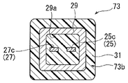
도 2 및 도 3 에 도시된 바와 같이, 페라이트 코어 (29) 는 삽입 구멍 (29A) 을 그 안에 구비한 정사각형 튜브의 형상을 갖는다. 제 1 및 제 2 버스 바아들 (25 및 27) 은 각각의 제 1 및 제 2 버스 바아들 (25 및 27) 의 제 2 평탄 부분들 (25C 및 27C) 이 삽입 구멍 (29A) 에 위치되도록 삽입 구멍 (29A) 을 통해 통과된다. 따라서 삽입 구멍 (29A) 을 통해 통과된 제 2 평탄 부분들 (25C 및 27C) 은 페라이트 코어 (29) 에 의해 둘러싸인다. 평탄 부분들 (25C 및 27C) 은 제 2 평탄 부분들 (25C 및 27C) 과 페라이트 코어 (29) 의 내부 표면 사이에 접촉을 방지하도록 삽입 구멍 (29A) 을 형성하는 페라이트 코어 (29) 의 내부 표면으로부터 이간된 거리로 배치된다. 그러나, 제 1 및 제 2 버스 바아들 (25 및 27) 이 알루미늄 합금과 같은 낮은 자기 투과성을 갖는 재료로 제조되는 경우에, 제 2 평탄 부분들 (25C 및 27C) 은 삽입 구멍 (29A) 을 형성하는 페라이트 코어 (29) 의 내부 표면과 접촉하여 배치될 수 있다.2 and 3, the
도 2 에 도시된 바와 같이, 제 1 및 제 2 버스 바아들 (25 및 27) 및 페라이트 코어 (29) 는 각각의 제 1 평탄 부분들 (25A 및 27A) 의 일단부들 및 각각의 제 3 평탄 부분들 (25E 및 27E) 의 일단부들을 제외하고 수지 절연기 (31) 로 덮혀진다. 도 3 에 도시된 바와 같이, 급전 어셈블리 (73) 에서 제 2 평탄 부분들 (25C 및 27C) 과 삽입 구멍 (29) 을 형성하는 페라이트 코어 (29) 의 내부 표면 사이의 공간은 수지 절연기 (31) 로써 충전된다. 그러나, 제 1 및 제 2 버스 바아들 (25 및 27) 이 낮은 자기 투과성을 갖는 재료로 제조되거나 충분한 이간된 거리가 임의의 다른 부재에 의해 제 2 평탄 부분들 (25 및 27) 과 페라이트 코어 (29) 의 내부 표면 사이에서 보장되는 경우에, 제 2 평탄 부분들 (25 및 27) 과 페라이트 코어 (29) 의 내부 표면 사이의 공간은 수지 절연기 (31) 로써 충전되지 않을 수 있다.As shown in Figure 2, the first and second bus bars 25 and 27 and the
상기 설명된 바와 같이, 수지 절연기 (31) 로써 제 1 및 제 2 버스 바아들 (25 및 27) 및 페라이트 코어 (29) 를 덮음으로써, 제 1 어셈블리 부분 (73A), 제 2 어셈블리 부분 (73B), 및 제 3 어셈블리 부분 (73C) 은, 도 1 에 도시된 바와 같이 급전 어셈블리 (73) 로 형성된다. 제 1 어셈블리 부분 (73A) 은 제 1 평탄 부분들 (25A 및 27A) 및 수지 절연기 (31) 를 포함한다. 제 2 어셈블리 부분 (73B) 은 연결 부분들 (25B 및 27B), 제 2 평탄 부분들 (25C 및 27C), 슬로프형 부분들 (25D 및 27D), 페라이트 코어 (29), 및 수지 절연기 (31) 를 포함한다. 제 3 어셈블리 부분 (73C) 은 제 3 평탄 부분들 (25E 및 27E) 및 수지 절연기 (31) 를 포함한다.By covering the first and second bus bars 25 and 27 and the
급전 어셈블리 (73) 에서, 구동 샤프트 (15) 의 축방향으로 측정된 바와 같이, 제 1 평탄 부분들 (25A 및 27A) 및 제 3 평탄 부분들 (25E 및 27E) 의 연장 방향에 수직한 방향으로의 제 2 어셈블리 부분 (73B) 의 두께는 각각 동일한 축방향으로 제 1 평탄 부분들 (25A 및 27A) 및 제 3 평탄 부분들 (25E 및 27E) 의 연장 방향에 수직한 방향으로의 제 1 어셈블리 부분 (73A) 및 제 3 어셈블리 부분 (73C) 의 두께보다 두껍다. 따라서, 급전 어셈블리 (73) 는 제 2 어셈블리 부분 (73B) 에서 돌기부를 갖는다.In the
급전 어셈블리 (73) 는 제 2 어셈블리 부분 (73B) 의 일부가 수용 공간 (75) 에 수용되는 방식으로 수용 챔버 (16) 에 설정되고 제 1 및 제 2 버스 바아들 (25 및 27) 은 제 1 및 제 2 버스 바아들 (25 및 27) 의 일단부들의 각각 또는 제 1 평탄 부분들 (25A 및 27A) 의 일단부의 각각이 급전 포트 (17) 로부터 노출된 상태로 수용 챔버 (16) 에 수용된다. 따라서 제 2 어셈블리 부분 (73B) 의 일부가 수용 공간 (75) 에 수용됨으로써 페라이트 코어 (29) 의 일부는 수용 공간 (75) 에 배치된다. 즉, 페라이트 코어 (29) 의 일부는 커버 (9) 의 연결 부분 (90A) 및 덮개 부분 (90B) 과 마주보는 관계로 수용 공간 (75) 에 배치된다.The
상기 설명된 바와 같이, 제 3 평탄 부분 (25E 및 27E) 의 일단부들은 커넥터 (71A) 를 통해 인버터 회로 (71) 에 연결되고 제 1 평탄 부분들 (25A 및 27A) 의 일단부들은 리드 와이어를 통해 급전부에 연결된다. 그러므로, 제 1 및 제 2 버스 바아들 (25 및 27) 은 인버터 회로 (71) 및 급전부에 전기적으로 연결되어 직류 전류가 급전부로부터 인버터 회로 (71) 로 공급된다.As described above, one ends of the third planar portions 25E and 27E are connected to the
전동 압축기에서, 인버터 회로 (71) 는 전원으로부터의 직류 전류를 교류 전류로 변환하면서 스테이터 (11) 에 제공된 코일에 전력을 공급하여, 모터 부품 (3) 의 로터 (13) 및 구동 샤프트 (15) 는 구동되어 회전된다. 로터 (13) 및 구동 샤프트 (15) 의 회전은 냉매 가스가 흡입 구멍을 통해 압축 부품 (5) 내로 흡인되고, 압축 부품 (5) 에서 압축되고, 토출 구멍을 통해 압축 부품 (5) 의 외부로 토출되게 만든다.The
제 1 및 제 2 버스 바아들 (25 및 27) 의 제 2 평탄 부분들 (25C 및 27C) 이 페라이트 코어 (29) 에 의해 각각 둘러싸이는 본 실시형태의 전동 압축기에서, 페라이트 코어 (29) 는 인버터 회로 (71) 가 전원으로부터의 DC 전력을 AC 전력으로 변환할 때 발생되고 제 1 버스 바아들 (25 및 27) 을 통해 방사되는 전자기 노이즈를 흡수한다. 페라이트 코어 (29) 는 또한 차량 상에 장착된 다른 장치들에 의해 발생된 전자기 노이즈를 흡수한다. 더욱이, 인버터 회로 (71) 는 상기 인버터 회로 (71) 외측에서 발생되는 전자기 노이즈에 민감하지 않게 된다.In the motor-driven compressor of the present embodiment in which the second flat portions 25C and 27C of the first and second bus bars 25 and 27 are surrounded by the
본 실시형태의 전동 압축기는 커버 (9) 자체의 사이즈에서의 증가를 방지하면서 큰 사이즈의 페라이트 코어 (29) 의 사용을 허용한다.The motor-driven compressor of this embodiment allows the use of the
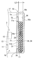
제 1 실시형태에 따른 전동 압축기의 효과들은 도 4 에 도시된 비교 실시형태에 따른 전동 압축기와의 비교에 기초하여 구체적으로 설명될 것이다. 비교 실시형태에 따른 전동 압축기의 설명에서, 제 1 실시형태에 따른 전동 압축기와의 차이점들만이 다뤄질 것이며, 제 1 실시형태 및 비교 실시형태에 따른 전동 압축기들과 공통된 구성 성분들 및 구성들은 동일한 도면 부호들로 표현될 것이며 그 상세한 설명은 생략될 것이다. 비교 실시형태에 따른 전동 압축기는 커버 (10) 를 갖는다. 커버 (10) 는 바닥 벽 (10A) 및 구동 샤프트 (15) 의 축방향으로 상기 바닥 벽 (10A) 으로부터 제 2 하우징 (1B) 을 향해 연장되는 주변 벽 (10B) 을 포함한다. 바닥 벽 (10A) 은 90 과 같은 돌출 부분을 갖지 않는다. 즉, 바닥 벽 (10A) 은 편평하게 형성된다. 그러므로, 커버 (10) 는 75 와 같은 수용 공간을 그 안에 갖지 않는다.The effects of the motor-driven compressor according to the first embodiment will be specifically described based on a comparison with the motor-driven compressor according to the comparative embodiment shown in Fig. In the description of the motor-driven compressor according to the comparative embodiment, only the differences from the motor-driven compressor according to the first embodiment will be dealt with, and the constituent components and configurations common to the motor-driven compressors according to the first embodiment and the comparative embodiment are the same And will not be described in detail. The motor-driven compressor according to the comparative embodiment has the
비교 실시형태에 따른 전동 압축기는 제 1 및 제 2 버스 바아들 (26 및 28) 및 페라이트 코어 (29) 가 수지 절연기 (31) 로 덮혀진 급전 어셈블리 (74) 를 사용한다. 제 1 및 제 2 버스 바아들 (26 및 28) 은 구동 샤프트 (15) 의 직경 방향으로 연장되도록 배치되지만, 굴곡부를 갖지 않는다. 제 1 및 제 2 버스 바아들 (26 및 28) 의 일단부들은 예를 들면 리드 와이어를 통해 전원에 연결되고, 그 타단부들은 커넥터 (71A) 를 통해 인버터 회로 (71) 에 연결된다. 구동 샤프트 (15) 의 축방향으로 측정된 바와 같이 급전 어셈블리 (74) 의 두께는 실질적으로 일정하다.The electric compressor according to the comparative embodiment uses the
비교 실시형태에 따른 전동 압축기에서, 그러므로 구동 샤프트 (15) 의 축방향으로의 커버 (10) 의 주변 벽 (10B) 의 치수는 급전 어셈블리 (74) 를 수용 챔버 (16) 에 수용하기 위해 증가될 필요가 있고, 이는 커버 (10) 그 자체의 사이즈에서 증가를 포함한다. 비교 실시형태에 따른 전동 압축기에서, 급전 어셈블리 (74) 를 마주보는 인버터 회로 (71) 의 표면과 커버 (10) 의 바닥 벽 (10A) 의 내부 표면 사이의 거리는 L2 로써 나타낸다.The dimension of the peripheral wall 10B of the
도 4 의 비교 실시형태의 전동 압축기에 따르면, 커버 (10) 의 사이즈를 유지하면서 페라이트 코어 (29) 를 제공하도록, 페라이트 코어 (29) 의 사이즈는 감소될 필요가 있다. 차량 상에 장착될 비교 실시형태에 따른 전동 압축기에서는, 그러나 큰 전류가 전원으로부터 인버터 회로 (71) 로 공급되고, 그러므로 그러한 소형화된 페라이트 코어 (29) 는 전자기 노이즈를 만족스럽게 흡수할 수 없다.4, the size of the
이와 대조적으로, 제 1 실시형태에 따른 전동 압축기는 돌출 부분 (90) 을 그 커버 (9) 의 바닥 벽 (9A) 에서 갖고 제 1 및 제 2 버스 바아들 (25 및 27) 은 굴곡부들 (250 및 270) 을 각각 형성하는 연결 부분들 (25B 및 27B), 제 2 평탄 부분들 (25C 및 27C), 및 슬로프형 부분들 (25D 및 27D) 을 각각 갖는다. 급전 어셈블리 (73) 에서, 구동 샤프트 (15) 의 축방향으로의 제 2 어셈블리 부분 (73B) 의 두께는 동일한 방향으로의 제 1 어셈블리 부분 (73A) 및 제 3 어셈블리 부분 (73C) 의 두께보다 두껍다. 급전 어셈블리 (73) 의 제 2 어셈블리 부분 (73B) 의 일부는 커버 (9) 의 돌출 부분 (90) 에서 형성된 수용 공간 (75) 에 수용된다.In contrast, the electric compressor according to the first embodiment has the projecting
제 1 실시형태에 따른 전동 압축기에서, 급전 어셈블리 (73) 를 마주보는 인버터 회로 (71) 의 표면과 커버 (9) 의 덮개 부분 (90B) 의 내부 표면 사이에 거리는 도 4 의 거리 (L2) 에 상응한다. 급전 어셈블리 (73) 를 마주보는 인버터 회로 (71) 의 표면과 돌출 부분 (90) 을 배제하는 커버 (9) 의 내부 표면, 즉 바닥 벽 (9A) 의 평탄 부분 (9C) 의 내부 표면 사이의 거리는 L1 으로 나타내고, 이는 도 4 에 도시된 상기 언급된 거리 (L2) 보다 짧다. 보다 구체적으로, 제 1 실시형태에 따른 전동 압축기에서, 급전 어셈블리 (73) 를 마주보는 인버터 회로 (71) 의 표면으로부터 거리 (L2) 로 이간된 커버 (9) 의 일부는 커버 (9) 의 제한된 일부에서만 형성되고, 그 결과로써 전자기 노이즈를 만족스럽게 흡수할 정도로 충분히 큰 사이즈의 페라이트 코어 (29) 가 커버 (9) 의 사이즈 및 따라서 전동 압축기 그 자체의 사이즈를 유지하면서 사용될 수 있다.In the motor-driven compressor according to the first embodiment, the distance between the surface of the
그러므로, 제 1 실시형태에 따른 전동 압축기는 용이한 장착을 제공하고 적어도 제 1 및 제 2 버스 바아들 (25 및 27) 로부터 방사되는 전자기 노이즈를 만족스럽게 흡수할 수 있다.Therefore, the motor-driven compressor according to the first embodiment provides easy mounting and can satisfactorily absorb electromagnetic noise radiated from at least the first and second bus bars 25 and 27.
더욱이, 제 1 실시형태에 따른 전동 압축기에서, 급전 어셈블리 (73) 는 수지 절연기 (31) 에 의해 제 1 및 제 2 버스 바아들 (25 및 27) 및 페라이트 코어 (29) 를 일체화함으로써 형성되고, 제 1 및 제 2 버스 바아들 (25 및 27) 은 수지 절연기 (31) 에 의해 커버 (9) 로부터 적절히 절연된다. 부가적으로, 수지 절연기 (31) 는 제 1 및 제 2 버스 바아들 (25 및 27) 및 페라이트 코어 (29) 가 커버 (9) 의 수용 챔버 (16) 에서 제 위치에 용이하게 수용되는 것을 허용한다.Furthermore, in the motor-driven compressor according to the first embodiment, the
더욱이, 제 1 실시형태에 따른 전동 압축기에서, 슬로프형 부분들 (25D 및 27D) 과 제 1 및 제 2 하우징들 (1A 및 1B) 사이의 거리가 제 2 평탄 부분 (25C) 을 향해 증가하도록 슬로프형 부분들 (25D 및 27D) 은 형성되고, 페라이트 코어 (29) 는 제 3 평탄 부분들 (25E 및 27E) 측으로부터 페라이트 코어 (29) 를 통해 제 1 및 제 2 버스 바아들 (25 및 27) 을 통과함으로써 제 2 평탄 부분들 (25C 및 27C) 에 배치된다. 그러므로, 슬로프형 부분들 (25D 및 27D) 의 제공은 제 2 평탄 부분들 (25C 및 27C) 에서 페라이트 코어 (29) 의 배치를 용이하게 만든다.Furthermore, in the motor-driven compressor according to the first embodiment, the distance between the sloped portions 25D and 27D and the first and second housings 1A and 1B increases toward the second flat portion 25C, Shaped portions 25D and 27D are formed and the
더욱이, 제 1 실시형태에 따른 전동 압축기에서, 금속으로 제조된 커버 (9) 는 또한 인버터 회로 (71) 에서 발생되고 제 1 및 제 2 버스 바아들 (25 및 27) 로부터 차량의 다른 장치들로 방사되는 전자기 노이즈의 영향 및 또한 커버 (9) 의 외측으로부터 인버터 회로 (71) 상으로의 전자기 노이즈의 영향을 추가로 감소시키는 전자기 차폐를 제공한다.Furthermore, in the motor-driven compressor according to the first embodiment, the
제 2 실시형태Second Embodiment
본 발명의 제 2 실시형태에 따른 전동 압축기가 지금부터 도 5 및 도 6 을 참조하여 설명될 것이다. 제 2 실시형태에 따른 전동 압축기는 제 1 실시형태의 페라이트 코어 (29) 에 상응하는 페라이트 코어 (290) 를 갖는다. 페라이트 코어 (290) 는 페라이트 코어 (290) 가 제 1 페라이트 코어 (35) 및 제 2 페라이트 코어 (37) 를 포함하는 스플릿 (split) 타입이라는 점에서 페라이트 코어 (29) 와 상이하다. 도 6 에 도시된 바와 같이, 제 1 및 제 2 페라이트 코어들 (35 및 37) 은 리세스들 (35A 및 37B) 을 갖는 U-형상의 단면으로 각각 형성된다. 제 1 페라이트 코어 (35) 의 리세스 (35A) 및 제 2 페라이트 코어 (37) 의 리세스 (37B) 는 제 2 평탄 부분들 (25C 및 27C) 을 둘러싸는 방식으로 서로 정합된다. 제 2 실시형태에 따른 전동 압축기의 나머지 구성은 제 1 실시형태의 구성과 실질적으로 동일하고, 그러므로 제 1 및 제 2 실시형태들에 따른 전동 압축기들과 공통적인 구성 요소들 및 구성들은 동일한 도면 부호들로 표현될 것이며 그 상세한 설명은 생략될 것이다.An electric compressor according to a second embodiment of the present invention will now be described with reference to Figs. 5 and 6. Fig. The motor-driven compressor according to the second embodiment has a
제 2 실시형태에 따른 전동 압축기에서, 제 1 및 제 2 페라이트 코어들 (35 및 37) 은 제 2 평탄 부분들 (25C 및 27C) 을 둘러싸고, 제 1 및 제 2 버스 바아들 (25 및 27) 은 반드시 제 1 및 제 2 페라이트 코어들 (35 및 37) 을 통해 각각 삽입될 필요는 없다. 그러므로, 제 2 실시형태에 따른 전동 압축기에서, 페라이트 코어 (290) 는 제 1 및 제 2 버스 바아들 (25 및 27) 에서 보다 용이하게 제공될 수 있다. 제 1 실시형태를 참조하여 설명된 효과들은 또한 제 2 실시형태에 대해서도 적용된다.In the motor-driven compressor according to the second embodiment, the first and
제 3 실시형태Third Embodiment
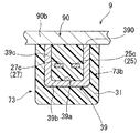
본 발명의 제 3 실시형태에 따른 전동 압축기는 도 7 및 도 8 을 참조하여 지금부터 설명될 것이다. 제 3 실시형태에 따른 전동 압축기는 제 1 실시형태의 페라이트 코어 (29) 대신에 페라이트 코어 (39) 를 갖는다. 도 8 에 도시된 바와 같이, 페라이트 코어 (39) 는 리세스 (39A) 를 갖는 U-형상의 단면으로 형성된다. 구체적으로, 페라이트 코어 (39) 는 제 2 평탄 부분들 (25C 및 27C) 을 둘러싸도록 이간 부분들 (39C) 의 쌍 및 상기 이간 부분들 (39C) 을 연결하는 평탄 부분 (39B) 을 포함한다. 보다 구체적으로, 이간 부분들 (39C) 은 평탄 부분 (39B) 의 대향하는 단부들로부터 커버 (9) 의 덮개 부분 (90B) 을 향해 연장되고 덮개 부분 (90B) 의 내부 표면과 직접 접촉하는 단부들 (390) 을 갖는다. 페라이트 코어 (39) 는 이간 부분들 (39C) 의 단부들 (390) 이 덮개 부분 (90B) 의 내부 표면과 더 이상 접촉하지 않거나, 또는 페라이트 코어 (39) 의 이간 부분들 (39C) 의 단부들 (390) 이 수지 절연기 (31) 로써 절연될 수 있도록 형성될 수 있다는 것에 주목해야 한다. 제 3 실시형태에 따른 전동 압축기의 나머지 구성은 제 1 실시형태의 구성과 실질적으로 동일하고, 그러므로 제 1 및 제 3 실시형태들에 따른 전동 압축기에 공통된 구성 요소들 및 구성들은 동일한 도면 부호들로 표현될 것이며 그 상세한 설명은 생략될 것이다.A motor-driven compressor according to a third embodiment of the present invention will now be described with reference to Figs. 7 and 8. Fig. The electric compressor according to the third embodiment has a
제 3 실시형태에 따른 전동 압축기는 또한 제 2 실시형태에 따른 전동 압축기와 동일한 효과들을 나타낸다.The motor-driven compressor according to the third embodiment also exhibits the same effects as those of the motor-driven compressor according to the second embodiment.
제 4 실시형태Fourth Embodiment
본 발명의 제 4 실시형태에 따른 전동 압축기는 지금부터 도 9 를 참조하여 설명될 것이다. 제 4 실시형태에 따른 전동 압축기는 제 1 실시형태에 따른 전동 압축기의 커버 (9) 에 상응하는 커버 (41) 를 갖는다. 커버 (41) 는 수지로 제조된 커버 본체 (410) 및 금속으로 제조된 차폐 커버 (411) 를 포함한다.An electric compressor according to a fourth embodiment of the present invention will now be described with reference to Fig. The motor-driven compressor according to the fourth embodiment has a
상기 커버 (9) 의 경우에서와 같이, 커버 본체 (410) 는 바닥 벽 (41A) 및 주변 벽 (41B) 을 포함한다. 바닥 벽 (41A) 은 평탄 부분 (41C) 을 포함한다. 제 1 실시형태의 커버 (9) 와 유사하게, 커버 본체 (410) 는 또한 돌출 부분 (90) 을 포함한다. 차폐 커버 (411) 는 커버 본체 (410) 의 외부 윤곽을 따르도록 형성된다. 제 4 실시형태에 따른 전동 압축기의 나머지 구성은 제 1 실시형태의 구성과 실질적으로 동일하고, 그러므로 제 1 및 제 4 실시형태들에 따른 전동 압축기들에 공통된 구성 요소들 및 구성들은 동일한 도면 부호들로 표현될 것이며 그 상세한 설명은 생략될 것이다.As in the case of the
제 4 실시형태에 따른 전동 압축기에서, 커버 본체 (410) 는 수지로 제조되고, 이는 전동 압축기의 중량을 감소시키는 데 도움을 준다. 커버 본체 (410) 의 외부 표면에 부착된 차폐 커버 (411) 는 수용 챔버 (16) 에 대해 전자기 차폐를 제공한다. 제 1 실시형태를 참조하여 언급된 효과들은 또한 제 4 실시형태에도 적용된다.In the motor-driven compressor according to the fourth embodiment, the
도 10 에 도시된 바와 같이, 차폐 커버 (411) 는 인서트 몰딩에 의해 형성될 수 있다는 것에 주목해야 한다. 더욱이, 도 11 에 도시된 바와 같이, 차폐 커버 (411) 는 커버 본체 (410) 의 내부 표면에 또는 커버 본체 (410) 의 제 1 및 제 2 버스 바아들 (25 및 27) 측에 제공될 수 있다. 이러한 경우들에서, 제 1 및 제 2 버스 바아들 (25 및 27) 과 차폐 커버 (411) 사이에서의 절연이 커버 본체 (410) 에 의해 보장된다면, 제 1 및 제 2 버스 바아들 (25 및 26) 과 페라이트 코어 (29) 는 수지 절연기 (31) 로써 반드시 절연될 필요는 없다. 따라서, 전동 압축기는 사이즈가 증가되는 것으로부터 방지된다.It should be noted that, as shown in Fig. 10, the shielding
제 5 실시형태Fifth Embodiment
본 발명의 제 5 실시형태에 따른 전동 압축기는 지금부터 도 12 를 참조하여 설명될 것이다. 제 5 실시형태에 따른 전동 압축기는 제 1 실시형태의 제 1 및 제 2 버스 바아들 (25 및 27) 에 상응하는 제 1 및 제 2 버스 바아들 (51 및 53) 을 갖는다. 제 1 및 제 2 버스 바아들 (51 및 53) 은, 제 1 및 제 2 버스 바아들 (51 및 53) 이 선행하는 실시형태들의 25E 및 27E 와 같은 제 3 평탄 부분들 및 슬로프형 부분들 (25D 및 27D) 을 각각 갖지 않는다는 점에서 제 1 실시형태 내지 제 4 실시형태에 따른 전동 압축기에서의 제 1 및 제 2 버스 바아들 (25 및 27) 과 상이하다. 제 2 평탄 부분들 (51C 및 53C) 의 일단부들은 커넥터 (71A) 를 통해 인버터 회로 (71) 에 연결된다. 제 1 및 제 2 버스 바아들 (51 및 53) 의 제 1 평탄 부분들 (51A 및 53A) 의 일단부들은 리드 와이어 (도시생략) 를 통해 전원에 연결된다. 제 1 평탄 부분들 (51A 및 53A) 및 제 2 평탄 부분들 (51C 및 53C) 은 각각 연결 부분들 (51B 및 53B) 을 통해 서로 연결된다. 제 1 평탄 부분들 (51A 및 53A) 의 일단부들은 인버터 회로 (71) 에 연결될 수 있고 제 2 평탄 부분들 (51C 및 53C) 의 일단부들은 리드 와이어를 통해 전원에 연결될 수 있다는 것에 주목해야 한다.An electric compressor according to a fifth embodiment of the present invention will now be described with reference to Fig. The motor-driven compressor according to the fifth embodiment has first and second bus bars 51 and 53 corresponding to the first and second bus bars 25 and 27 of the first embodiment. The first and second bus bars 51 and 53 are configured such that the first and second bus bars 51 and 53 are spaced apart from the third planar portions and slope portions, such as 25E and 27E of the previous embodiments 25D, and 27D, respectively, in the motor compressors according to the first to fourth embodiments. One ends of the second planar portions 51C and 53C are connected to the
제 1 및 제 2 버스 바아들 (51 및 53) 은 연결 부분들 (51B 및 53B) 및 제 2 평탄 부분들 (51C 및 53C) 에 의해 각각 형성된 굴곡부들 (510 및 530) 을 각각 포함한다. 제 1 평탄 부분들 (51A 및 53A) 보다 제 1 및 제 2 하우징들 (1A 및 1B) 으로부터 보다 먼 거리로 이간된 굴곡부들 (510 및 530) 은 본 발명의 연장부에 상응한다.The first and second bus bars 51 and 53 each include bent portions 510 and 530 formed by the connecting portions 51B and 53B and the second flat portions 51C and 53C, respectively. The bent portions 510 and 530 separated by a greater distance from the first and second housings 1A and 1B than the first flat portions 51A and 53A correspond to the extensions of the present invention.
더욱이, 급전 어셈블리 (73) 는 제 1 어셈블리 부분 (73A) 및 제 2 어셈블리 부분 (73B) 을 포함한다. 제 1 어셈블리 부분 (73A) 은 제 1 평탄 부분들 (51A 및 53A) 및 수지 절연기 (31) 의 일부를 포함한다. 제 2 어셈블리 부분 (73B) 은 연결 부분들 (51B 및 53B), 제 2 평탄 부분들 (51C 및 53C), 페라이트 코어 (29), 및 수지 절연기 (31) 의 일부를 포함한다.Furthermore, the
제 5 실시형태에 따른 전동 압축기는 커버 (9) 의 형상이 부분적으로 변경되고 커버 (9) 의 돌출 부분이 연결 부분 (90A), 주변 벽 (9B), 및 굴곡부들 (510 및 530) 을 위한 공간을 덮는 덮개 부분 (90B) 을 포함한다는 점에서 제 1 실시형태에 따른 전동 압축기와 상이하다.The electric compressor according to the fifth embodiment is a compressor in which the shape of the
본 발명에 따른 전동 압축기에서 사용된 압축 부품으로서, 스크롤 타입 압축 부품, 스와시 플레이트 타입 압축 부품, 또는 베인 타입 압축 부품이 사용될 수 있다.As the compression component used in the electric compressor according to the present invention, a scroll type compression component, a swash plate type compression component, or a vane type compression component may be used.
전자기 노이즈 제거 부재로서, 자기 코어, 예를 들면 페라이트 코어 및 더스트 (dust) 코어가 사용될 수 있다.As the electromagnetic noise removing member, a magnetic core, for example, a ferrite core and a dust core may be used.
커버는 금속 및 수지의 조합 뿐만 아니라, 금속 단독으로 제조될 수 있다. 두개의 내부 전도체들은 다양한 형상들, 예를 들면 플레이트 형상, 로드 형상, 또는 임의의 다른 형상들로 제조될 수 있다.The cover can be made of metal alone as well as a combination of metal and resin. The two internal conductors may be manufactured in a variety of shapes, for example, a plate shape, a rod shape, or any other shape.
제 5 실시형태에 따른 전동 압축기에서, 급전 어셈블리 (73) 가 수용 챔버 (16) 에 제위치에 수용되는 제 1 실시형태와 유사하게, 제 2 어셈블리 부분 (73B) 의 일부는 수용 공간 (75) 에 수용되고 페라이트 코어 (29) 의 일부는 수용 공간 (75) 에 배치된다. 제 5 실시형태에 따른 전동 압축기의 나머지 구성은 제 1 실시형태의 구성과 실질적으로 동일하고, 그러므로 제 1 및 제 5 실시형태들에 따른 전동 압축기와 공통된 구성 요소들 및 구성들은 동일한 도면 부호들로 표현될 것이며 그 상세한 설명은 생략될 것이다.In the motor-driven compressor according to the fifth embodiment, similarly to the first embodiment in which the
제 5 실시형태에 따른 전동 압축기는 또한 제 1 실시형태에 따른 전동 압축기와 동일한 효과들을 나타낸다.The motor-driven compressor according to the fifth embodiment also exhibits the same effects as those of the motor-driven compressor according to the first embodiment.
본 발명은 제 1 실시형태 내지 제 5 실시형태와 관련하여 설명되었다. 그러나, 본 발명은 상기 설명된 실시형태들에 제한되지 않고, 본 발명의 범위 및 사상 안에서 다양하게 변경될 수 있다는 것이 이해되어야만 한다.The present invention has been described with reference to the first to fifth embodiments. It should be understood, however, that the invention is not limited to the embodiments described above, but may be varied within the scope and spirit of the invention.
제 1 실시형태 내지 제 5 실시형태에 따른 전동 압축기의 구성 요소들은 이로서 본 발명의 전동 압축기를 제조하도록 서로 적절히 대체될 수 있다. 예를 들면, 제 4 실시형태에 따른 전동 압축기의 커버 (41) 는 제 2 실시형태에 따른 전동 압축기를 위한 커버로서 적용될 수 있다.The components of the motor-driven compressor according to the first to fifth embodiments can thus be appropriately replaced with each other to produce the motor-driven compressor of the present invention. For example, the
커버 (9) 가 낮은 자기 투과성을 갖는 재료, 예를 들면 알루미늄 합금으로 제조되는 경우에, 페라이트 코어들 (29, 290, 및 39) 은 수지 절연기 (31) 로 덮혀지지 않을 수 있다.The
제 1 실시형태 내지 제 5 실시형태에 따른 전동 압축기들에서, 급전 어셈블리 (73) 는 제 1 평탄 부분들 (25A 및 27A) 의 일단부들이 급전 포트 (17) 의 에 배치된 상태로 수용 챔버 (16) 에 수용된다. 그러나, 급전 어셈블리 (73) 의 구성은 이에 제한되지 않고 제 1 평탄 부분들 (25A 및 27B) 의 일단부들은 제 1 평탄 부분들 (25A 및 27B) 의 일단부들이 수용 챔버 (16) 의 외측에 제공된 전원에 연결 가능한 한 급전 포트 (17) 에 배치되지 않을 수 있다.In the motor compressors according to the first to fifth embodiments, the
제 1 실시형태 내지 제 5 실시형태에 따른 전동 압축기들에서들에서, 커버들 (9 및 41) 의 주변 벽들 (9B 및 41B) 의 단부들은, 각각 제 2 하우징 (1B) 의 바닥 벽 (1E) 에 고정된다. 그러나, 커버들 (9 및 41) 은 그러한 구성에 제한되지 않고 커버들 (9 및 21) 은 인버터 장치 (7) 를 그 안에 수용할 수 있는 16 과 같은 임의의 수용 챔버가 커버들 (9 및 41) 과 제 1 및 제 2 하우징들 (1A 및 1B) 을 포함하는 하우징 어셈블리 사이에 제공되는 한 임의의 적절한 위치에 고정될 수 있다.In the motor compressors according to the first to fifth embodiments, the ends of the peripheral walls 9B and 41B of the
제 1 실시형태 내지 제 5 실시형태에 따른 전동 압축기들의 커버들 (9 및 41) 은 폐쇄된 단부를 구비한 원통 형상을 갖는다. 그러나, 커버들 (9 및 41) 의 형상은 이에 제한되지 않고, 그러나 커버들 (9 및 41) 은 수용 챔버 (16) 를 그 안에 갖는 데 충분히 큰 부피를 구비한 정육면체 또는 직육면체의 형상을 가질 수 있다.The
제 1 실시형태 내지 제 4 실시형태에 따른 전동 압축기들에서, 페라이트 코어 (29) 는 제 2 평탄 부분들 (25C 및 27C) 에 인접하도록 그리고 이를 둘러싸도록 제공될 수 있다. 대안적으로, 페라이트 코어 (29) 는 연결 부분들 (25B 및 27B) 또는 슬로프형 부분들 (25D 및 27D) 에 인접하도록 그리고 이를 둘러싸도록 제공될 수 있다. 즉, 페라이트 코어 (29) 는 페라이트 코어 (29) 가 굴곡부들 (250 및 270) 을 형성하는 연결 부분들 (25B 및 27B), 제 2 평탄 부분들 (25C 및 27C), 및 슬로프형 부분들 (25D 및 27D) 중 적어도 임의의 하나를 둘러싸는 한 임의의 위치에 제공될 수 있다. 동일한 것이 제 5 실시형태에 따른 전동 압축기에 적용된다.In the motor compressors according to the first to fourth embodiments, the
제 1 실시형태 내지 제 4 실시형태에 따른 전동 압축기들에서, 각각의 제 1 및 제 2 버스 바아들 (25) 의 연결 부분들 (25B 및 27B), 제 2 평탄 부분들 (25C 및 27C) 및 슬로프형 부분들 (25D 및 27D) 은 그 인접한 부분들에 대해 각지게 연장되도록 형성된다. 본 발명에 따르면, 그러나 제 1 및 제 2 버스 바아들 (25 및 27) 은 굴곡부들 (250 및 270) 에 대해 아치형 커브로써 형성될 수 있다. 유사하게, 돌출 부분 (90) 은 코너를 갖지 않는 커브로써 형성될 수 있다. 동일한 것이 제 5 실시형태에 따른 전동 압축기에 적용된다.In the motor compressors according to the first to fourth embodiments, the connecting portions 25B and 27B, the second flat portions 25C and 27C of the respective first and second bus bars 25 and The slope portions 25D and 27D are formed to extend angularly with respect to their adjacent portions. According to the present invention, however, the first and second bus bars 25 and 27 may be formed as arcuate curves with respect to the
본 발명은 차량 등에서 공조 장치에 적용될 수 있다.The present invention can be applied to an air conditioning apparatus in a vehicle or the like.
Claims (4)
상기 하우징은 상기 모터 부품 및 상기 압축 부품이 배치된 하우징 본체, 및 상기 하우징 본체에 고정되어 상기 인버터 장치를 상기 하우징 본체에 수용하기 위해 상기 하우징 본체와의 사이에서 수용 챔버를 형성하는 커버를 포함하고,
상기 인버터 장치는,
인버터 회로,
두개의 내부 전도체들로서, 그들의 일단부들에서 상기 인버터 회로에 전기적으로 연결되고 그들의 타단부들에서 전원에 전기적으로 연결 가능하고, 상기 전원은 상기 수용 챔버 외측에 제공되어 상기 전원으로부터 상기 인버터 회로로 직류 전류를 공급하는, 상기 두개의 내부 전도체들, 및
상기 두개의 내부 전도체들을 둘러싸서 적어도 상기 두개의 내부 전도체들로부터 방사되는 전자기 노이즈를 흡수하는 전자기 노이즈 제거 부재를 포함하고,
상기 커버는,
상기 하우징 본체로부터 이간된 바닥 벽, 및
상기 바닥 벽으로부터 상기 하우징 본체를 향해 연장되는 주변 벽을 포함하고,
상기 바닥 벽은 상기 하우징 본체로부터 이간되어 돌출되어 내부에 수용 공간을 형성하는 돌출 부분을 갖고,
상기 두개의 내부 전도체들의 각각은,
연장부로서, 그 일단부에서 상기 인버터 회로에 연결되거나 또는 그 일단부에서 상기 전원에 연결 가능한, 상기 연장부, 및
상기 연장부의 타단부에 연결되는 굴곡부를 포함하고,
상기 굴곡부는 상기 연장부보다 상기 하우징 본체로부터 더 떨어져 배치되고 상기 굴곡부의 적어도 일부는 상기 전자기 노이즈 제거 부재로 덮혀지고,
상기 전자기 노이즈 제거 부재의 적어도 일부는 상기 수용 공간에 배치되는, 전동 압축기.1. An electric compressor comprising a housing, a motor component, a compression component driven by the motor component and compressing a refrigerant gas, and an inverter device for driving the motor component,
The housing includes a housing main body in which the motor part and the compression part are disposed, and a cover fixed to the housing main body to form an accommodating chamber between the housing main body and the housing main body for accommodating the inverter device in the housing main body ,
The inverter device includes:
Inverter circuit,
The inverter circuit being electrically connected to the inverter circuit at one of its ends and being electrically connectable to a power source at the other ends thereof, the power source being provided outside of the receiving chamber to supply a DC current , The two internal conductors supplying
And an electromagnetic noise removing member surrounding the two inner conductors to absorb electromagnetic noise emitted from at least the two inner conductors,
The cover
A bottom wall spaced apart from the housing main body, and
And a peripheral wall extending from the bottom wall toward the housing body,
The bottom wall has a protruding portion protruding from the housing main body to form a receiving space therein,
Each of the two internal conductors has a &
An extension, connected to the inverter circuit at one end thereof or connectable to the power supply at one end thereof,
And a bent portion connected to the other end of the extended portion,
Wherein the bent portion is disposed further away from the housing main body than the extending portion, at least a part of the bent portion is covered with the electromagnetic noise removing member,
And at least a part of the electromagnetic noise removing member is disposed in the accommodating space.
상기 바닥 벽은 평탄 부분을 포함하고,
상기 돌출 부분은 상기 평탄 부분에 평행하게 형성되는 덮개 부분, 및
상기 평탄 부분 및 상기 덮개 부분과 일체로 형성되고 상기 평탄 부분 및 상기 덮개 부분을 연결하는 연결 부분을 포함하는, 전동 압축기.The method according to claim 1,
Wherein the bottom wall includes a flat portion,
The projecting portion includes a cover portion formed parallel to the flat portion, and
And a connecting portion formed integrally with the flat portion and the cover portion and connecting the flat portion and the cover portion.
상기 두개의 내부 전도체들 및 상기 전자기 노이즈 제거 부재는 절연 부재로 덮혀져서 일체형 급전 어셈블리를 형성하고,
상기 급전 어셈블리는 상기 연장부 및 상기 절연 부재의 일부를 갖는 제 1 어셈블리 부분 및 상기 굴곡부, 상기 전자기 노이즈 제거 부재, 및 상기 절연 부재의 일부를 갖는 제 2 어셈블리 부분을 포함하고,
상기 연장부의 연장 방향에 수직한 방향으로의 상기 제 2 어셈블리 부분의 두께는 상기 연장부의 상기 연장 방향에 수직한 방향으로의 상기 제 1 어셈블리 부분의 두께보다 두꺼운, 전동 압축기.3. The method according to claim 1 or 2,
The two internal conductors and the electromagnetic noise removing member are covered with an insulating member to form an integral power supply assembly,
The feed assembly includes a first assembly portion having the extension and a portion of the insulating member and a second assembly portion having the bent portion, the electromagnetic noise removing member, and a portion of the insulating member,
Wherein a thickness of the second assembly portion in a direction perpendicular to an extending direction of the extending portion is thicker than a thickness of the first assembly portion in a direction perpendicular to the extending direction of the extending portion.
상기 굴곡부는 상기 연장부로부터 이간된 거리에 배치된 이간 부분, 및
상기 이간 부분과 상기 연장부의 상기 타단부를 연결하는 연결 부분을 포함하고,
상기 연결 부분은 상기 연결 부분의 적어도 일부와 상기 하우징 본체 사이의 거리가 상기 이간 부분을 향해 증가하도록 형성되는, 전동 압축기.3. The method according to claim 1 or 2,
The bent portion being a spaced apart portion disposed at a distance apart from the extending portion, and
And a connecting portion connecting the spacing portion and the other end portion of the extending portion,
Wherein the connecting portion is formed such that a distance between at least a portion of the connecting portion and the housing body increases toward the spacing portion.
Applications Claiming Priority (2)
| Application Number | Priority Date | Filing Date | Title |
|---|---|---|---|
| JPJP-P-2014-234530 | 2014-11-19 | ||
| JP2014234530A JP6314801B2 (en) | 2014-11-19 | 2014-11-19 | Electric compressor |
Publications (2)
| Publication Number | Publication Date |
|---|---|
| KR20160059984A true KR20160059984A (en) | 2016-05-27 |
| KR101718634B1 KR101718634B1 (en) | 2017-03-21 |
Family
ID=55855695
Family Applications (1)
| Application Number | Title | Priority Date | Filing Date |
|---|---|---|---|
| KR1020150161948A KR101718634B1 (en) | 2014-11-19 | 2015-11-18 | Electric compressor |
Country Status (3)
| Country | Link |
|---|---|
| JP (1) | JP6314801B2 (en) |
| KR (1) | KR101718634B1 (en) |
| DE (1) | DE102015222767B4 (en) |
Families Citing this family (3)
| Publication number | Priority date | Publication date | Assignee | Title |
|---|---|---|---|---|
| KR102606337B1 (en) * | 2017-02-17 | 2023-11-27 | 한온시스템 주식회사 | Cooling fan motor assembly |
| US11533012B2 (en) | 2019-10-07 | 2022-12-20 | Toyota Motor Engineering & Manufacturing North America, Inc. | High-density integrated power control assemblies having shared cooling system with a motor |
| JP7342766B2 (en) * | 2020-03-31 | 2023-09-12 | 株式会社豊田自動織機 | electric compressor |
Citations (3)
| Publication number | Priority date | Publication date | Assignee | Title |
|---|---|---|---|---|
| JP2009156213A (en) * | 2007-12-27 | 2009-07-16 | Mitsubishi Heavy Ind Ltd | Inverter integrated electric compressor |
| JP2010209788A (en) * | 2009-03-10 | 2010-09-24 | Mitsubishi Heavy Ind Ltd | Inverter integrated type electric compressor |
| JP2014031771A (en) * | 2012-08-03 | 2014-02-20 | Toyota Industries Corp | Motor driven compressor |
Family Cites Families (2)
| Publication number | Priority date | Publication date | Assignee | Title |
|---|---|---|---|---|
| JP5091521B2 (en) * | 2007-03-29 | 2012-12-05 | 三菱重工業株式会社 | Integrated electric compressor |
| JP5591089B2 (en) * | 2010-12-10 | 2014-09-17 | 三菱重工業株式会社 | Inverter-integrated electric compressor |
-
2014
- 2014-11-19 JP JP2014234530A patent/JP6314801B2/en active Active
-
2015
- 2015-11-18 DE DE102015222767.7A patent/DE102015222767B4/en active Active
- 2015-11-18 KR KR1020150161948A patent/KR101718634B1/en active IP Right Grant
Patent Citations (3)
| Publication number | Priority date | Publication date | Assignee | Title |
|---|---|---|---|---|
| JP2009156213A (en) * | 2007-12-27 | 2009-07-16 | Mitsubishi Heavy Ind Ltd | Inverter integrated electric compressor |
| JP2010209788A (en) * | 2009-03-10 | 2010-09-24 | Mitsubishi Heavy Ind Ltd | Inverter integrated type electric compressor |
| JP2014031771A (en) * | 2012-08-03 | 2014-02-20 | Toyota Industries Corp | Motor driven compressor |
Also Published As
| Publication number | Publication date |
|---|---|
| JP2016098678A (en) | 2016-05-30 |
| DE102015222767B4 (en) | 2021-03-25 |
| KR101718634B1 (en) | 2017-03-21 |
| JP6314801B2 (en) | 2018-04-25 |
| DE102015222767A1 (en) | 2016-05-19 |
Similar Documents
| Publication | Publication Date | Title |
|---|---|---|
| US8618703B2 (en) | Motor driven compressor | |
| US20150056086A1 (en) | Electric compressor | |
| US8210833B2 (en) | Motor-driven compressor | |
| US8323005B2 (en) | Motor-driven compressor | |
| US9447924B2 (en) | Motor driven compressor for a vehicle | |
| JP6256382B2 (en) | Electric compressor | |
| US9394905B2 (en) | Motor-driven compressor including a shield to block electromagnetic noise | |
| US10707715B2 (en) | Motor-driven compressor | |
| KR101718634B1 (en) | Electric compressor | |
| KR101994913B1 (en) | Electric compressor | |
| US20220278481A1 (en) | Seal arrangement of a plug-in connection for establishing electrical connections and a device for driving a compressor with the seal arrangement | |
| US8876496B2 (en) | Offset electrical terminal box with angled studs | |
| JP2006042409A (en) | Motor integrated compressor | |
| EP2197097B1 (en) | Inverter-integrated electric compressor and coil component for inverter thereof | |
| US10125775B2 (en) | Motor-driven compressor | |
| US20140377095A1 (en) | Motor-driven compressor | |
| EP2623786B1 (en) | Motor-driven compressor | |
| CN111756189B (en) | Electric compressor | |
| JP7444107B2 (en) | electric compressor | |
| EP3392504A1 (en) | Electrically driven compressor | |
| JP2024037419A (en) | electric compressor |
Legal Events
| Date | Code | Title | Description |
|---|---|---|---|
| A201 | Request for examination | ||
| E701 | Decision to grant or registration of patent right | ||
| FPAY | Annual fee payment |
Payment date: 20200302 Year of fee payment: 4 |