KR20160034288A - A tube for heat transfer - Google Patents
A tube for heat transfer Download PDFInfo
- Publication number
- KR20160034288A KR20160034288A KR1020167000742A KR20167000742A KR20160034288A KR 20160034288 A KR20160034288 A KR 20160034288A KR 1020167000742 A KR1020167000742 A KR 1020167000742A KR 20167000742 A KR20167000742 A KR 20167000742A KR 20160034288 A KR20160034288 A KR 20160034288A
- Authority
- KR
- South Korea
- Prior art keywords
- tube
- fin
- pin
- head
- shaft
- Prior art date
Links
Images
Classifications
-
- F—MECHANICAL ENGINEERING; LIGHTING; HEATING; WEAPONS; BLASTING
- F28—HEAT EXCHANGE IN GENERAL
- F28F—DETAILS OF HEAT-EXCHANGE AND HEAT-TRANSFER APPARATUS, OF GENERAL APPLICATION
- F28F1/00—Tubular elements; Assemblies of tubular elements
- F28F1/10—Tubular elements and assemblies thereof with means for increasing heat-transfer area, e.g. with fins, with projections, with recesses
- F28F1/40—Tubular elements and assemblies thereof with means for increasing heat-transfer area, e.g. with fins, with projections, with recesses the means being only inside the tubular element
-
- F—MECHANICAL ENGINEERING; LIGHTING; HEATING; WEAPONS; BLASTING
- F28—HEAT EXCHANGE IN GENERAL
- F28F—DETAILS OF HEAT-EXCHANGE AND HEAT-TRANSFER APPARATUS, OF GENERAL APPLICATION
- F28F1/00—Tubular elements; Assemblies of tubular elements
- F28F1/10—Tubular elements and assemblies thereof with means for increasing heat-transfer area, e.g. with fins, with projections, with recesses
-
- F—MECHANICAL ENGINEERING; LIGHTING; HEATING; WEAPONS; BLASTING
- F28—HEAT EXCHANGE IN GENERAL
- F28F—DETAILS OF HEAT-EXCHANGE AND HEAT-TRANSFER APPARATUS, OF GENERAL APPLICATION
- F28F2215/00—Fins
- F28F2215/04—Assemblies of fins having different features, e.g. with different fin densities
Abstract
상기 튜브의 내부 표면이 패턴으로 홈가공된 열전달을 위한 튜브이다. 상기 패턴은 상이한 형상들을 가진 제 1 핀 (10) 과 제 2 핀 (20) 을 포함하고, 상기 제 1 핀은 일체로 형성된 샤프트 및 헤드를 포함하고, 상기 샤프트는 상기 내부 표면에서부터 상기 내부 표면으로부터 먼 방향으로 연장되며, 상기 헤드는 상기 샤프트에서부터 상기 내부 표면으로부터 먼 방향으로 연장된다. 상기 튜브의 횡단면에서, 상기 헤드의 원주방향 폭은 상기 샤프트의 원주방향 폭보다 크다.And the inner surface of the tube is a tube for heat transfer grooved in a pattern. Wherein the pattern comprises a first pin (10) and a second pin (20) having different shapes, the first pin comprising an integrally formed shaft and a head, the shaft having an inner surface And the head extends from the shaft in a direction away from the inner surface. In the cross-section of the tube, the circumferential width of the head is greater than the circumferential width of the shaft.
Description
본 발명은 열전달을 위한 튜브, 특히 내부 표면에 2 가지 종류의 핀들을 가진 열전달을 위한 내부-홈가공된 튜브 (inner-grooved tube) 에 관한 것이다.The present invention relates to a tube for heat transfer, in particular an inner-grooved tube for heat transfer with two kinds of fins on the inner surface.
이음매 없는 튜브들, 특히 구리 및 알루미늄과 같은 특히 높은 열전도성 재료들로 제조된 튜브들은, 열 교환기들에서 열 운반 유체를 순환시켜 열전달하는데 사용된다. 이러한 튜브들은, 열 운반 유체와 튜브의 내부 표면 사이의 열교환 영역을 향상시키기 위해 내부 표면의 영역을 증가시키고 그리고 열교환 효율을 향상시키는 난류를 발생시키도록 내부에 홈가공된다.Seamless tubes, especially tubes made of highly thermally conductive materials, such as copper and aluminum, are used to heat transfer the heat transfer fluid in heat exchangers. These tubes are grooved internally to increase the area of the inner surface and to create turbulence to improve heat exchange efficiency to improve the heat exchange area between the heat transfer fluid and the inner surface of the tube.
열교환기에서 매끄러운 내부 표면을 가진 튜브 대신에 내부-홈가공된 튜브를 사용함으로써, 열교환 효율을 상당히 향상시키고 그리하여 환경 보호를 위해 에너지를 절감한다. 향상된 효율에도 불구하고, 종래의 내부-홈가공된 튜브들은, 최대 열전달 용량의 한계로 인해, 일부 대형 파워 장비들에 대하여 열분산 요건들을 만족할 수 없다.Using an internally-grooved tube instead of a tube with a smooth inner surface in the heat exchanger significantly improves heat exchange efficiency and thus saves energy for environmental protection. Despite improved efficiency, conventional inner-grooved tubes can not satisfy the heat dissipation requirements for some large power devices due to the limit of maximum heat transfer capacity.
본 개시의 목적은 열교환 효율이 향상된 내부-홈가공된 튜브를 제공하는 것이다.It is an object of the present disclosure to provide an inner-grooved tube with improved heat exchange efficiency.
본 개시는 열전달을 위한 튜브에 관한 것으로서, 상기 튜브의 내부 표면은 패턴으로 홈가공되고, 상기 패턴은 상이한 형상들을 가진 제 1 핀과 제 2 핀을 포함하고, 상기 제 1 핀은 일체로 형성된 샤프트 및 헤드를 포함하고, 상기 샤프트는 상기 내부 표면에서부터 상기 내부 표면으로부터 먼 방향으로 연장되며, 상기 헤드는 상기 샤프트에서부터 상기 내부 표면으로부터 먼 방향으로 연장되며, 상기 튜브의 횡단면에서, 상기 헤드의 원주방향 폭은 상기 샤프트의 원주방향 폭보다 크다.The present disclosure relates to a tube for heat transfer, wherein an inner surface of the tube is grooved into a pattern, the pattern comprising a first pin and a second pin having different shapes, And a head extending from the inner surface in a direction away from the inner surface, the head extending from the shaft in a direction away from the inner surface, and at a cross-section of the tube, The width is larger than the circumferential width of the shaft.
열전달을 위한 본원의 내부-홈가공된 튜브는, 열전달 영역 및 모세관 원동력 (driving force) 을 증가시켜, 열전달 능력 및 열전달 효율을 향상시킨다.The present inner-grooved tube for heat transfer increases heat transfer area and capillary driving force, thereby improving heat transfer capability and heat transfer efficiency.
전술한 일반적인 설명 및 이하의 상세한 설명 양자는 예시적이고 설명만을 위한 것이며 그리고 청구되는 바와 같이, 본원을 제한하려는 것이 아님을 이해해야 한다.It is to be understood that both the foregoing general description and the following detailed description are exemplary and explanatory only and are not intended to limit the invention, as claimed.
본 명세서에 포함되고 그리고 본 명세서의 일부를 구성하는 첨부된 도면들은 본원의 여러 가지 실시형태들을 설명하고 그리고 설명과 함께 본원의 원리들을 설명하는데 사용된다.BRIEF DESCRIPTION OF THE DRAWINGS The accompanying drawings, which are incorporated in and form a part of this specification, illustrate various embodiments of the invention and are used to explain the principles of the invention, along with the description.
도 1 은 본 개시의 일 실시형태에 따른 내부-홈가공된 튜브의 종단면도를 도시한다.
도 2 는 본 개시의 일 실시형태에 따른 내부-홈가공된 튜브의 횡단면도를 도시한다.
도 3 은 본 개시의 다른 실시형태에 따른 내부-홈가공된 튜브의 횡단면도를 도시한다.BRIEF DESCRIPTION OF THE DRAWINGS Figure 1 shows a longitudinal section of an inner-grooved tube according to an embodiment of the present disclosure.
2 shows a cross-sectional view of an inner-grooved tube according to an embodiment of the present disclosure;
3 shows a cross-sectional view of an inner-grooved tube according to another embodiment of the present disclosure;
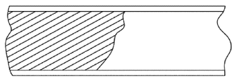
도 1 은 본 개시의 일 실시형태에 따른 내부-홈가공된 튜브 (1) 의 종단면도를 도시한다. 튜브는, 천공 로드 (piercing rod) 에 걸쳐 중실의 빌렛 (solid billet) 을 인발하여 중공의 쉘을 형성함으로써 제조되는 바와 같이 (반대로, 용접된 튜브는, 플레이트를 압연하고 이 플레이트의 2 개의 가장자리를 용접함으로써 제조됨) 이음매가 없고; 하지만 이 튜브는 용접된 튜브일 수도 있다. 튜브의 내부 표면은 패턴으로 홈가공된다. 도 1 에 도시된 튜브는 내부에 나사가공되고, 즉 튜브의 내부 표면이 나선형 나사로 홈가공되었지만, 내부 표면은 어떠한 적절한 패턴으로, 예를 들어 튜브의 종축을 따라서 연장되는 복수의 리브들, 또는 튜브의 내부 표면상의 나선형으로 홈가공될 수 있음을 당업자는 알 것이다.1 shows a longitudinal section view of an inner-grooved tube 1 according to an embodiment of the present disclosure. A tube is produced by drawing a solid billet through a piercing rod to form a hollow shell (as opposed to a welded tube, which is formed by rolling the plate and forming two edges of the plate Manufactured by welding) without seams; However, this tube may be a welded tube. The inner surface of the tube is grooved into a pattern. The tube shown in Fig. 1 is threaded internally, i. E. The inner surface of the tube is grooved with a helical thread, but the inner surface can have any suitable pattern, for example a plurality of ribs extending along the longitudinal axis of the tube, It will be appreciated by those skilled in the art that spiral grooving may be performed on the inner surface of the substrate.
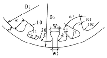
도 2 는 본 개시의 일 실시형태에 따른 내부-홈가공된 튜브 (1) 의 횡단면도를 도시한다. 도 2 에 도시된 튜브 (1) 는 둥근 단면을 가진다. 튜브의 단면은, 당업자에 의해 이해되는 바와 같이, 플레이트 형상, 직사각형 형상 또는 특정 적용을 위한 적절한 어떠한 다른 형상일 수 있다. 도 2 에 도시된 튜브 (1) 는 외경 (Do), 내경 (Di) 및 벽 두께 (t) 를 가진다.Figure 2 shows a cross-sectional view of an inner-grooved tube 1 according to one embodiment of the present disclosure. The tube 1 shown in Fig. 2 has a round cross-section. The cross-section of the tube may be in the form of a plate, a rectangle, or any other suitable shape for a particular application, as will be understood by those skilled in the art. The tube 1 shown in Fig. 2 has an outer diameter Do, an inner diameter Di and a wall thickness t.
튜브 (1) 의 내부 표면은 패턴으로 홈가공되고, 이 패턴은 제 1 핀 (10) 과 제 2 핀 (20) 을 포함한다. 제 1 핀 (10) 과 제 2 핀 (20) 각각은 튜브의 내부 표면에 내부 나사산을 형성하도록 튜브의 종방향에 대하여 각을 이루어 연장된다. 튜브의 내부 나사산들과 종축 사이의 각은, 0°~ 60°, 바람직하게는 2°~ 45°이다. 제 1 핀 (10) 과 제 2 핀 (20) 각각은 튜브의 종방향을 따라서 일정한 횡단면을 가진다.The inner surface of the tube 1 is grooved into a pattern, which includes a
제 1 핀 (10) 과 제 2 핀 (20) 은 상이한 형상들을 가지고, 제 1 핀 (10) 은 샤프트 (102) (즉, 융기부) 및 이 샤프트 (102) 와 일체로 형성된 헤드 (101) 를 포함한다. 샤프트 (102) 는 내부 표면에서부터 이 내부 표면으로부터 먼 방향으로 연장되고, 헤드 (101) 는 샤프트 (102) 에서부터 내부 표면으로부터 먼 방향으로 연장된다. 튜브의 횡단면에서, 헤드 (101) 의 원주방향 폭 (Wl) 은 샤프트 (102) 의 원주방향 폭 (W2) 보다 더 크다. 제 1 핀 (10) 의 반경방향으로의 핀 높이는 H1 이고, 헤드 (101) 의 높이는 샤프트 (102) 의 높이보다 작거나 동일하다. 바람직하게는, 헤드 (101) 의 원주 방향으로의 폭 (Wl) 은, 헤드가 내부 표면으로부터 멀리 연장됨에 따라 증가되거나, 우선 헤드가 내부 표면으로부터 멀리 연장됨에 따라 증가된 후 헤드의 선단 쪽으로 감소한다. 샤프트 (102) 의 원주방향으로의 폭 (W2) 은 샤프트가 내부 표면으로부터 멀리 연장함에 따라 일정하게 될 수 있다.The
도 2 에 도시된 바와 같이, 제 1 핀 (10) 의 어덴덤 각 (addendum angle) 은 α1 이다. 제 1 핀 (10) 의 디덴덤 (dedendum) 은, 제 1 코너 (11) 에서, 곡선 천이부에 의해 튜브 (1) 의 내부 표면에 원활하게 이어진다. 제 1 코너 (11) 의 곡률은 R1 이다. 예를 들어, H1 은 0.05 mm ~ 0.30 mm 일 수 있고, Rl 은 0 ~ 0.15 mm 일 수 있다. As shown in FIG. 2, the addendum angle of the
제 2 핀 (20) 의 반경방향으로의 높이는 제 1 핀 (10) 의 높이 (H1) 보다 낮은 H2 이다. 바람직하게는, 제 2 핀 (20) 의 높이 (H2) 는 제 1 핀 (10) 의 높이 (H1) 의 1/3 ~ 1/2 이다. 제 2 핀 (20) 의 상부에서의 폭, 즉 어덴덤 폭은 제 2 핀 (20) 의 바닥에서의 폭, 즉 디덴덤 폭보다 더 좁다. 바람직하게는, 제 2 핀 (20) 의 원주방향으로의 폭은, 제 2 핀 (20) 이 내부 표면으로부터 멀리 연장함에 따라 감소된다. 도 2 에 도시된 바와 같이, 제 2 핀 (20) 의 어덴덤 각은 5°~ 60° 의 α2 이다. 제 2 핀 (20) 의 디덴덤은, 제 2 코너 (21) 에서, 곡선 천이부에 의해 튜브 (1) 의 내부 표면에 원활하게 이어진다. 제 2 코너 (21) 의 곡률은 R2 이다. 예를 들어, H2 는 0.005 mm ~ H1 일 수 있고, R2 는 0 ~ 0.15 mm 일 수 있다.The height of the
도 2 에 도시된 실시형태에 있어서, 제 1 핀 (10) 의 원주방향 핀 개수 (N1) 는 제 2 핀 (20) 의 원주방향 핀 개수 (N2) 와 동일하다. 제 1 핀 (10) 과 제 2 핀 (20) 은 교대로 배열된다. 제 1 핀 (10) 의 핀 높이 (H1) 는 제 2 핀 (20) 의 핀 높이 (H2) 보다 더 크다. 예를 들어, 핀 높이 (H2) 는 0.005 mm ~ 핀 높이 (H1) 이다.2, the number of circumferential pins N1 of the
교대로 배열된 제 1 핀 (10) 과 제 2 핀 (20) 은, 튜브의 내부 표면의 영역을 증가시키고, 열 운반 유체와 튜브의 내부 표면 사이의 열전달 영역을 증가시키며, 그리고 더 높은 열전달 효율을 제공할 것이다. 추가로, 공동은, 제 1 핀 (10) 과 제 2 핀 (20) 사이에 형성되고, 튜브의 모세관 효과들을 향상시키며, 강한 모세관 원동력을 제공하여 열전달 성능을 향상시킨다.The alternately arranged first and
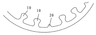
도 3 은 본 개시의 다른 실시형태에 따른 내부 홈가공된 튜브 (1') 의 횡단면도를 도시한다. 이전의 실시형태와 동일하게, 튜브 (1') 의 내부 표면상의 내부 나사산들은 또한 제 1 핀 (10') 과 제 2 핀 (20') 을 포함한다. 본 실시형태는, 제 1 핀 (10') 의 원주방향 핀 개수 (N1) 가 제 2 핀 (20') 의 원주방향 핀 개수 (N2) 의 두배인 점에서만 이전의 실시형태와 상이하다. 2 개의 제 1 핀 (10') 과 1 개의 제 2 핀 (20') 마다 교대로 배열된다. 하지만, 제 1 핀 (10') 의 원주방향 핀 개수 (N1) 가 제 2 핀 (20') 의 원주방향 핀 개수 (N2) 의 어떠한 다른 정수배일 수 있고 그리고 제 2 핀은 제 1 핀들에 의해 이격됨을 당업자라면 이해할 것이다. 대안으로서, 제 1 핀과 제 2 핀이 교대로 배열되는 한, 제 1 핀 (10') 의 원주방향 핀 개수 (N1) 는 제 2 핀 (20') 의 원주방향 핀 개수 (N2) 의 정수배가 되어야 하는 것은 아니다.Figure 3 shows a cross-sectional view of an inner grooved tube 1 'according to another embodiment of the present disclosure. As in the previous embodiment, the internal threads on the inner surface of the tube 1 'also include a first pin 10' and a second pin 20 '. This embodiment is different from the previous embodiment only in that the circumferential pin number N1 of the first pin 10 'is twice the circumferential pin number N2 of the second pin 20'. Are alternately arranged for each of two first pins 10 'and one second pin 20'. However, the number of circumferential pins N1 of the first pin 10 'can be any other multiple of the number N2 of circumferential pins of the second pin 20', and the second pin can be rotated by the first pins It will be understood by those skilled in the art. Alternatively, as long as the first pin and the second pin are arranged alternately, the number of circumferential pins N1 of the first pin 10 'is an integer number N2 of the circumferential pins of the second pin 20' It does not have to be doubled.
더욱이, 어덴덤 폭이 제 1 핀의 높이의 절반에서의 폭보다 크다면, 제 1 핀 (10) 은 도 2 및 도 3 에 도시된 바와 같은 형상으로 한정되지 않는다. 예를 들어, 제 1 핀 (10) 이 대략 역전된 사다리꼴일 수 있다. 어덴덤 폭이 디덴덤 폭보다 작으면, 제 2 핀 (20) 은 도 2 및 도 3 에 도시된 바와 같은 형상으로 한정되지 않는다. 예를 들어, 제 2 핀 (20) 이 대략 사다리꼴일 수 있다. 이러한 상황들에서, 제 2 핀 (20) 의 높이는 제 1 핀 (10) 의 높이보다 낮을 수 있다.Further, if the addendum width is larger than the width at half the height of the first fin, the
이전의 사양에서, 다양한 바람직한 실시형태들은 첨부된 도면들을 참조하여 설명되었다. 하지만, 이하의 청구범위에 개시된 바와 같이 더 넓은 본원의 범위를 벗어나지 않으면서, 이에 다양한 다른 수정 및 변경들을 할 수 있고, 추가의 실시형태들을 실시할 수 있음이 명백하다. 그에 따라, 사양 및 도면들은 제한적인 관점 보다는 오히려 설명적인 것으로 간주된다.In the previous specification, various preferred embodiments have been described with reference to the accompanying drawings. It will, however, be evident that various other modifications and changes may be made, and additional embodiments may be practiced, without departing from the broader scope of the invention as set forth in the following claims. Accordingly, the specification and figures are to be regarded as illustrative rather than restrictive.
본 개시의 다른 실시형태들은 본원에 개시된 바의 사양 및 실시를 고려하여 당업자에게 명백할 것이다. 이러한 사양 및 실시예들은, 이하의 청구범위에 의해 개시된 본원의 진정한 범위 및 사상내에서 예시적으로만 고려되는 것임을 의도한 것이다.Other embodiments of the disclosure will be apparent to those skilled in the art in view of the specification and practice of the invention disclosed herein. These specifications and embodiments are intended to be exemplary only and are intended to be within the true scope and spirit of the invention disclosed by the following claims.
Claims (16)
상기 튜브의 내부 표면은 패턴으로 홈가공되고, 상기 패턴은 상이한 형상들을 가진 제 1 핀 (10) 과 제 2 핀 (20) 을 포함하고,
상기 제 1 핀 (10) 은 일체로 형성된 샤프트 (102) 및 헤드 (101) 를 포함하고, 상기 샤프트 (102) 는 상기 내부 표면에서부터 상기 내부 표면으로부터 먼 방향으로 연장되며, 상기 헤드 (101) 는 상기 샤프트 (102) 에서부터 상기 내부 표면으로부터 먼 방향으로 연장되며,
상기 튜브의 종축에 대하여 횡단면에서, 상기 헤드 (101) 의 원주방향 폭은 상기 샤프트 (102) 의 원주방향 폭보다 큰 것을 특징으로 하는, 열전달을 위한 튜브.As a tube for heat transfer,
The inner surface of the tube is grooved into a pattern, the pattern comprising a first fin (10) and a second fin (20) having different shapes,
The first pin 10 includes an integrally formed shaft 102 and a head 101 that extends from the inner surface in a direction away from the inner surface, Extending from the shaft (102) in a direction away from the inner surface,
Wherein a circumferential width of the head (101) is greater than a circumferential width of the shaft (102) in a transverse section with respect to the longitudinal axis of the tube.
상기 튜브의 횡단면에서, 상기 제 1 핀 (10) 의 반경방향으로의 핀 높이는 상기 제 2 핀 (20) 의 반경방향으로의 핀 높이보다 더 높은, 열전달을 위한 튜브.The method according to claim 1,
Wherein the radial fin height of the first fin (10) is greater than the radial fin height of the second fin (20) in the cross-section of the tube.
상기 제 2 핀 (20) 의 높이는 상기 제 1 핀 (10) 의 높이의 1/3 ~ 1/2 인, 열전달을 위한 튜브.3. The method of claim 2,
Wherein the height of the second fin (20) is 1/3 to 1/2 the height of the first fin (10).
상기 제 1 핀 (10) 의 원주방향 핀 개수는 상기 제 2 핀 (20) 의 원주방향 핀 개수의 정수배이고, 상기 제 2 핀 (20) 은 상기 제 1 핀 (10) 에 의해 이격되는, 열전달을 위한 튜브.3. The method of claim 2,
Wherein the number of circumferential pins of the first fin is an integral multiple of the number of circumferential pins of the second pin and the second pin is spaced apart by the first pin, Tube for.
상기 제 1 핀 (10) 의 원주방향 핀 개수는 상기 제 2 핀 (20) 의 원주방향 핀 개수와 동일하고, 상기 제 1 핀 (10) 과 상기 제 2 핀 (20) 은 교대로 배열되는, 열전달을 위한 튜브.5. The method of claim 4,
Wherein the number of circumferential pins of the first pin (10) is equal to the number of circumferential pins of the second pin (20), and the first pin (10) and the second pin (20) Tubes for heat transfer.
상기 튜브의 횡단면에서, 상기 헤드 (101) 의 반경방향으로의 높이는 상기 샤프트 (102) 의 반경방향으로의 높이보다 작거나 동일한, 열전달을 위한 튜브.The method according to claim 1,
Wherein the radial height of the head (101) in the cross-section of the tube is less than or equal to the radial height of the shaft (102).
상기 튜브의 횡단면에서, 상기 헤드 (101) 의 원주방향으로의 폭은 상기 헤드 (101) 가 상기 내부 표면으로부터 멀리 연장됨에 따라 증가되거나, 우선 상기 헤드 (101) 가 상기 내부 표면으로부터 멀리 연장됨에 따라 증가된 후 상기 헤드 (101) 의 선단 쪽으로 감소하는, 열전달을 위한 튜브.The method according to claim 1,
In the cross-section of the tube, the circumferential width of the head 101 increases as the head 101 extends away from the inner surface, or, first, as the head 101 extends away from the inner surface And decreases toward the tip of the head (101) after being increased.
상기 튜브의 횡단면에서, 상기 샤프트의 원주방향으로의 폭은 상기 샤프트가 상기 내부 표면으로부터 멀리 연장됨에 따라 일정한, 열전달을 위한 튜브.8. The method of claim 7,
Wherein the circumferential width of the shaft in the cross-section of the tube is constant as the shaft extends away from the inner surface.
상기 튜브의 횡단면에서, 상기 제 2 핀 (20) 의 원주방향으로의 폭은 상기 제 2 핀 (20) 이 상기 내부 표면으로부터 멀리 연장됨에 따라 감소하는, 열전달을 위한 튜브.The method according to claim 1,
Wherein in the cross-section of the tube, the circumferential width of the second fin (20) decreases as the second fin (20) extends away from the inner surface.
상기 제 1 핀 (10) 의 어덴덤 각은 5°~ 60°인, 열전달을 위한 튜브.10. The method of claim 9,
Wherein the addendum angle of the first fin (10) is between 5 [deg.] And 60 [deg.].
상기 제 1 핀 (10) 의 디덴덤 및 상기 제 2 핀 (20) 의 디덴덤은, 제 1 코너 (11) 및 제 2 코너 (21) 각각에서, 곡선 천이부에 의해 상기 튜브의 내부 표면에 원활하게 이어지는, 열전달을 위한 튜브.The method according to claim 1,
The derotation of the first pin 10 and the derotation of the second pin 20 are applied to the inner surface of the tube by a curved transition at the first corner 11 and the second corner 21, Tube for heat transfer smoothly.
상기 제 1 핀 (10) 과 상기 제 2 핀 (20) 각각은 상기 튜브의 내부 표면에 내부 나사산들을 형성하도록 상기 튜브의 종방향에 대하여 각을 이루어 연장되는, 열전달을 위한 튜브.The method according to claim 1,
Wherein each of the first fin (10) and the second fin (20) extends at an angle to the longitudinal direction of the tube to form internal threads on an inner surface of the tube.
상기 제 1 핀 (10) 과 상기 제 2 핀 (20) 각각은 상기 튜브의 종방향을 따라서 일정한 횡단면을 가지는, 열전달을 위한 튜브.13. The method of claim 12,
Wherein each of the first fin (10) and the second fin (20) has a constant cross-section along a longitudinal direction of the tube.
상기 튜브의 내부 나사산들과 종축 사이의 각은 0°~ 60°인, 열전달을 위한 튜브.13. The method of claim 12,
Wherein the angle between the internal threads of the tube and the longitudinal axis is 0 ° to 60 °.
상기 튜브의 내부 나사산들과 종축 사이의 각은 2°~ 45°인, 열전달을 위한 튜브.15. The method of claim 14,
Wherein the angle between the internal threads of the tube and the longitudinal axis is between 2 [deg.] And 45 [deg.].
상기 튜브는 이음매 없는, 열전달을 위한 튜브.16. The method according to any one of claims 1 to 15,
The tube is a seamless tube for heat transfer.
Applications Claiming Priority (3)
| Application Number | Priority Date | Filing Date | Title |
|---|---|---|---|
| CN201310301247.2A CN104296583B (en) | 2013-07-18 | 2013-07-18 | Female screw heat-transfer pipe |
| CN201310301247.2 | 2013-07-18 | ||
| PCT/EP2014/064939 WO2015007645A1 (en) | 2013-07-18 | 2014-07-11 | A tube for heat transfer |
Publications (1)
| Publication Number | Publication Date |
|---|---|
| KR20160034288A true KR20160034288A (en) | 2016-03-29 |
Family
ID=51176387
Family Applications (1)
| Application Number | Title | Priority Date | Filing Date |
|---|---|---|---|
| KR1020167000742A KR20160034288A (en) | 2013-07-18 | 2014-07-11 | A tube for heat transfer |
Country Status (8)
| Country | Link |
|---|---|
| US (1) | US9891009B2 (en) |
| EP (1) | EP3022509A1 (en) |
| JP (1) | JP2016524122A (en) |
| KR (1) | KR20160034288A (en) |
| CN (1) | CN104296583B (en) |
| CA (1) | CA2915173A1 (en) |
| MX (1) | MX369866B (en) |
| WO (1) | WO2015007645A1 (en) |
Families Citing this family (5)
| Publication number | Priority date | Publication date | Assignee | Title |
|---|---|---|---|---|
| US10988904B2 (en) * | 2016-08-18 | 2021-04-27 | Ian R. Cooke | Snow and ice melting device, system and corresponding methods |
| CN111465815B (en) * | 2017-10-13 | 2023-06-23 | 莱兹厄尔斯私人有限公司 | Air conditioning module |
| JP7116868B2 (en) * | 2017-12-07 | 2022-08-12 | Maアルミニウム株式会社 | Heat transfer tubes and heat exchangers with excellent expandability and thermal properties |
| US11322920B2 (en) * | 2019-05-03 | 2022-05-03 | Hydro Extrusion USA, LLC | Ribbed extruded electrical conduit |
| DE202019004184U1 (en) | 2019-10-10 | 2019-10-28 | Torsten Enders | Increase the transfer area in pipes |
Family Cites Families (13)
| Publication number | Priority date | Publication date | Assignee | Title |
|---|---|---|---|---|
| US2930405A (en) * | 1955-05-31 | 1960-03-29 | Brown Fintube Co | Tube with internal fins and method of making same |
| CA1063097A (en) * | 1976-01-26 | 1979-09-25 | David F. Fijas | Inner finned heat exchanger tube |
| JPS604797A (en) | 1983-06-21 | 1985-01-11 | Kobe Steel Ltd | Heat transfer tube equipped with groove on inner surface thereof and manufacture thereof |
| JPS63290395A (en) * | 1987-05-22 | 1988-11-28 | Hitachi Ltd | Heat transfer tube with inner grooves |
| US5655599A (en) * | 1995-06-21 | 1997-08-12 | Gas Research Institute | Radiant tubes having internal fins |
| US6883597B2 (en) | 2001-04-17 | 2005-04-26 | Wolverine Tube, Inc. | Heat transfer tube with grooved inner surface |
| FR2855601B1 (en) | 2003-05-26 | 2005-06-24 | Trefimetaux | GROOVED TUBES FOR THERMAL EXCHANGERS WITH TYPICALLY AQUEOUS MONOPHASIC FLUID |
| JP4665713B2 (en) * | 2005-10-25 | 2011-04-06 | 日立電線株式会社 | Internal grooved heat transfer tube |
| CN101004336A (en) * | 2007-01-19 | 2007-07-25 | 金龙精密铜管集团股份有限公司 | Female screw heat-transfer pipe |
| US20090294112A1 (en) * | 2008-06-03 | 2009-12-03 | Nordyne, Inc. | Internally finned tube having enhanced nucleation centers, heat exchangers, and methods of manufacture |
| CN102353296A (en) * | 2011-07-26 | 2012-02-15 | 金龙精密铜管集团股份有限公司 | Heat exchanger and internal threaded copper tube thereof |
| CN103063072A (en) * | 2013-01-10 | 2013-04-24 | 江苏萃隆精密铜管股份有限公司 | Heat-exchange tube |
| CN203489765U (en) * | 2013-07-18 | 2014-03-19 | 卢瓦塔埃斯波公司 | Female threaded heat transmission tube |
-
2013
- 2013-07-18 CN CN201310301247.2A patent/CN104296583B/en active Active
-
2014
- 2014-07-11 CA CA2915173A patent/CA2915173A1/en not_active Abandoned
- 2014-07-11 JP JP2016526550A patent/JP2016524122A/en active Pending
- 2014-07-11 MX MX2015018004A patent/MX369866B/en active IP Right Grant
- 2014-07-11 US US14/905,540 patent/US9891009B2/en active Active
- 2014-07-11 WO PCT/EP2014/064939 patent/WO2015007645A1/en active Application Filing
- 2014-07-11 KR KR1020167000742A patent/KR20160034288A/en not_active Application Discontinuation
- 2014-07-11 EP EP14738519.9A patent/EP3022509A1/en not_active Withdrawn
Also Published As
| Publication number | Publication date |
|---|---|
| CA2915173A1 (en) | 2015-01-22 |
| US20160138877A1 (en) | 2016-05-19 |
| CN104296583B (en) | 2019-02-05 |
| CN104296583A (en) | 2015-01-21 |
| MX2015018004A (en) | 2016-09-21 |
| MX369866B (en) | 2019-11-25 |
| JP2016524122A (en) | 2016-08-12 |
| EP3022509A1 (en) | 2016-05-25 |
| US9891009B2 (en) | 2018-02-13 |
| WO2015007645A1 (en) | 2015-01-22 |
Similar Documents
| Publication | Publication Date | Title |
|---|---|---|
| KR20160034288A (en) | A tube for heat transfer | |
| EP2354743A2 (en) | Double-pipe heat exchanger | |
| JP2006242529A (en) | Heat transfer pipe | |
| US20160361749A1 (en) | Heat exchanger manufacturing method and diameter enlargement tool | |
| JP2006514733A (en) | Enhanced heat exchanger tube with discontinuous bi-directionally inclined internal ribs | |
| JPH06201286A (en) | Heat transfer pipe | |
| US9541336B2 (en) | Evaporation heat transfer tube with a hollow cavity | |
| JP2012097920A (en) | Heat exchanger | |
| CN203758338U (en) | Irregular-section internal groove tube | |
| KR20150092151A (en) | A grooved tube | |
| EP2959251B1 (en) | Tube structures for heat exchanger | |
| US9733024B2 (en) | Tubing element with fins for a heat exchanger | |
| EP2941610B1 (en) | Tubing element for a heat exchanger means | |
| CN101813433B (en) | Enhanced heat transfer tube for condensation | |
| CN100498125C (en) | Evaporation box of hot end heat sink for semiconductor electronic refrigerator | |
| WO2015114015A1 (en) | Sectional uneven inner grooved tube | |
| CN203489765U (en) | Female threaded heat transmission tube | |
| JP2013092335A (en) | Aluminum capillary tube for heat exchanger, and heat exchanger using the same | |
| JP2009092269A (en) | Double tube-type heat exchanger | |
| CN106643259A (en) | Composite tooth-shaped internal thread copper pipe structure | |
| EP3126767B1 (en) | Spiral coils | |
| CN216245777U (en) | Heat transfer pipe with transition surface on fin | |
| EP2738505A1 (en) | Tubing element for a heat exchanger means | |
| CN113983851A (en) | Heat transfer pipe with transition surface on fin | |
| RU47502U1 (en) | MULTICHANNEL FLAT PRESSED TUBE |
Legal Events
| Date | Code | Title | Description |
|---|---|---|---|
| N231 | Notification of change of applicant | ||
| WITN | Withdrawal due to no request for examination |