KR20150136603A - Apparatus, systems, and methods for monitoring elevated temperatures in rotating couplings and drives - Google Patents
Apparatus, systems, and methods for monitoring elevated temperatures in rotating couplings and drives Download PDFInfo
- Publication number
- KR20150136603A KR20150136603A KR1020157028691A KR20157028691A KR20150136603A KR 20150136603 A KR20150136603 A KR 20150136603A KR 1020157028691 A KR1020157028691 A KR 1020157028691A KR 20157028691 A KR20157028691 A KR 20157028691A KR 20150136603 A KR20150136603 A KR 20150136603A
- Authority
- KR
- South Korea
- Prior art keywords
- temperature
- drive system
- magnetic drive
- transceiver
- monitoring
- Prior art date
Links
Images


Classifications
-
- H02P29/0044—
-
- G—PHYSICS
- G01—MEASURING; TESTING
- G01K—MEASURING TEMPERATURE; MEASURING QUANTITY OF HEAT; THERMALLY-SENSITIVE ELEMENTS NOT OTHERWISE PROVIDED FOR
- G01K1/00—Details of thermometers not specially adapted for particular types of thermometer
- G01K1/02—Means for indicating or recording specially adapted for thermometers
- G01K1/024—Means for indicating or recording specially adapted for thermometers for remote indication
-
- G—PHYSICS
- G01—MEASURING; TESTING
- G01K—MEASURING TEMPERATURE; MEASURING QUANTITY OF HEAT; THERMALLY-SENSITIVE ELEMENTS NOT OTHERWISE PROVIDED FOR
- G01K7/00—Measuring temperature based on the use of electric or magnetic elements directly sensitive to heat ; Power supply therefor, e.g. using thermoelectric elements
- G01K7/02—Measuring temperature based on the use of electric or magnetic elements directly sensitive to heat ; Power supply therefor, e.g. using thermoelectric elements using thermoelectric elements, e.g. thermocouples
-
- G—PHYSICS
- G11—INFORMATION STORAGE
- G11B—INFORMATION STORAGE BASED ON RELATIVE MOVEMENT BETWEEN RECORD CARRIER AND TRANSDUCER
- G11B33/00—Constructional parts, details or accessories not provided for in the other groups of this subclass
- G11B33/14—Reducing influence of physical parameters, e.g. temperature change, moisture, dust
-
- H—ELECTRICITY
- H02—GENERATION; CONVERSION OR DISTRIBUTION OF ELECTRIC POWER
- H02H—EMERGENCY PROTECTIVE CIRCUIT ARRANGEMENTS
- H02H7/00—Emergency protective circuit arrangements specially adapted for specific types of electric machines or apparatus or for sectionalised protection of cable or line systems, and effecting automatic switching in the event of an undesired change from normal working conditions
- H02H7/08—Emergency protective circuit arrangements specially adapted for specific types of electric machines or apparatus or for sectionalised protection of cable or line systems, and effecting automatic switching in the event of an undesired change from normal working conditions for dynamo-electric motors
- H02H7/085—Emergency protective circuit arrangements specially adapted for specific types of electric machines or apparatus or for sectionalised protection of cable or line systems, and effecting automatic switching in the event of an undesired change from normal working conditions for dynamo-electric motors against excessive load
- H02H7/0852—Emergency protective circuit arrangements specially adapted for specific types of electric machines or apparatus or for sectionalised protection of cable or line systems, and effecting automatic switching in the event of an undesired change from normal working conditions for dynamo-electric motors against excessive load directly responsive to abnormal temperature by using a temperature sensor
-
- H02K11/0015—
-
- H02K11/0047—
-
- H—ELECTRICITY
- H02—GENERATION; CONVERSION OR DISTRIBUTION OF ELECTRIC POWER
- H02K—DYNAMO-ELECTRIC MACHINES
- H02K11/00—Structural association of dynamo-electric machines with electric components or with devices for shielding, monitoring or protection
- H02K11/20—Structural association of dynamo-electric machines with electric components or with devices for shielding, monitoring or protection for measuring, monitoring, testing, protecting or switching
- H02K11/21—Devices for sensing speed or position, or actuated thereby
-
- H—ELECTRICITY
- H02—GENERATION; CONVERSION OR DISTRIBUTION OF ELECTRIC POWER
- H02K—DYNAMO-ELECTRIC MACHINES
- H02K11/00—Structural association of dynamo-electric machines with electric components or with devices for shielding, monitoring or protection
- H02K11/20—Structural association of dynamo-electric machines with electric components or with devices for shielding, monitoring or protection for measuring, monitoring, testing, protecting or switching
- H02K11/25—Devices for sensing temperature, or actuated thereby
-
- H—ELECTRICITY
- H02—GENERATION; CONVERSION OR DISTRIBUTION OF ELECTRIC POWER
- H02K—DYNAMO-ELECTRIC MACHINES
- H02K11/00—Structural association of dynamo-electric machines with electric components or with devices for shielding, monitoring or protection
- H02K11/30—Structural association with control circuits or drive circuits
- H02K11/35—Devices for recording or transmitting machine parameters, e.g. memory chips or radio transmitters for diagnosis
-
- H—ELECTRICITY
- H02—GENERATION; CONVERSION OR DISTRIBUTION OF ELECTRIC POWER
- H02K—DYNAMO-ELECTRIC MACHINES
- H02K21/00—Synchronous motors having permanent magnets; Synchronous generators having permanent magnets
- H02K21/02—Details
- H02K21/021—Means for mechanical adjustment of the excitation flux
- H02K21/022—Means for mechanical adjustment of the excitation flux by modifying the relative position between field and armature, e.g. between rotor and stator
- H02K21/025—Means for mechanical adjustment of the excitation flux by modifying the relative position between field and armature, e.g. between rotor and stator by varying the thickness of the air gap between field and armature
- H02K21/026—Axial air gap machines
-
- H—ELECTRICITY
- H02—GENERATION; CONVERSION OR DISTRIBUTION OF ELECTRIC POWER
- H02K—DYNAMO-ELECTRIC MACHINES
- H02K49/00—Dynamo-electric clutches; Dynamo-electric brakes
- H02K49/02—Dynamo-electric clutches; Dynamo-electric brakes of the asynchronous induction type
-
- H—ELECTRICITY
- H02—GENERATION; CONVERSION OR DISTRIBUTION OF ELECTRIC POWER
- H02P—CONTROL OR REGULATION OF ELECTRIC MOTORS, ELECTRIC GENERATORS OR DYNAMO-ELECTRIC CONVERTERS; CONTROLLING TRANSFORMERS, REACTORS OR CHOKE COILS
- H02P23/00—Arrangements or methods for the control of AC motors characterised by a control method other than vector control
- H02P23/14—Estimation or adaptation of motor parameters, e.g. rotor time constant, flux, speed, current or voltage
Abstract
자기 드라이브 시스템을 연속적으로 및 풍부하게 모니터하는 시스템은 자기 드라이브 시스템에 연결된 온도 센서를 포함한다. 온도 센서는, 온도 센서의 온도를 나타내는 출력 신호를 발생시키는 송신기에 연결된다. 시스템은 송수신기와 제어기를 포함하며, 송수신기는 송신기에 연결되고 송신기의 출력 신호를 수신하도록 구성된다. 제어기는 송수신기 및 자기 드라이브 시스템에 통신할 수 있도록 연결되며 송수신기로부터 수신된 하나 또는 그 이상의 신호에 기반하여 자기 드라이브 시스템의 작동을 제어하도록 구성된다. A system for continuously and abundantly monitoring a magnetic drive system includes a temperature sensor coupled to the magnetic drive system. The temperature sensor is connected to a transmitter which generates an output signal indicative of the temperature of the temperature sensor. The system includes a transceiver and a controller, wherein the transceiver is coupled to the transmitter and configured to receive an output signal of the transmitter. The controller is configured to communicate with the transceiver and the magnetic drive system and is configured to control operation of the magnetic drive system based on one or more signals received from the transceiver.
Description
이 출원은 2013년 3월 14일에 출원된 미국 가출원 제61/786,223호에 대한 미국특허법(35 U.S.C.) 제119조(e)의 이익을 주장하며, 이는 그 전체로서 여기에 참조로 포함된다. This application claims the benefit of United States Provisional Application No. 61 / 786,223, filed March 14, 2013, under 35 USC § 119 (e), which is incorporated herein by reference in its entirety.
본 개시는 온도 모니터링 장치, 시스템 및 방법에 관한 것이며, 더 구체적으로는, 자기 드라이브 시스템(magnetic drive system)의 온도 모니터링에 관한 것이다. The present disclosure relates to a temperature monitoring apparatus, system and method, and more particularly, to temperature monitoring of a magnetic drive system.
고정 갭(fixed gap) 자기 커플링 및/또는 가변속(adjustable speed) 드라이브 시스템을 포함할 수 있는 자기 드라이브 시스템은 모터로부터 부하(lood)로 에어 갭을 가로질러 토크를 전달함에 의해 작동한다. 장비의 구동하는 측 및 구동되는 측 사이에는 기계적인 연결이 없다. 토크는 드라이브 일측의 강력한 희토류 자석과 타측의 유도된 자기장의 상호작용에 의해 생성된다. 가변속 드라이브 시스템에서와 같이, 에어 갭 간격을 변화시킴으로써, 전달되는 토크의 양이 제어될 수 있으며, 이에 따라 속도 제어를 허용한다. A magnetic drive system, which may include a fixed gap magnetic coupling and / or an adjustable speed drive system, operates by transferring torque across the air gap from the motor to the lud. There is no mechanical connection between the driven and driven sides of the machine. Torque is generated by the interaction of the strong rare earth magnet on one side of the drive with the induced magnetic field on the other side. By varying the air gap distance, as in a variable speed drive system, the amount of transmitted torque can be controlled, thereby allowing speed control.
자기 드라이브 시스템은 통상적으로 마그네틱 로터 어셈블리(magnetic rotor assembly)와 컨덕터 로터 어셈블리(conductor rotor assembly)를 포함한다. 희토류 자석(magnet)을 포함하는 마그네틱 로터 어셈블리가 부하에 부착된다. 컨덕터 로터 어셈블리는 모터에 부착된다. 컨덕터 로터 어셈블리는 알루미늄, 구리, 또는 놋쇠와 같은 전도성 재료(conductive material)로 만들어진 로터를 포함한다. 가변속 드라이브 시스템과 같은 일부 자기 드라이브 시스템에서, 자기 드라이브 시스템은 또한 마그넷(magnet) 로터와 컨덕터 로터 사이의 에어 갭 간격을 제어하는 액추에이션(actuation) 구성요소를 포함한다. Magnetic drive systems typically include a magnetic rotor assembly and a conductor rotor assembly. A magnetic rotor assembly comprising a rare earth magnet is attached to the load. The conductor rotor assembly is attached to the motor. The conductor rotor assembly includes a rotor made of a conductive material such as aluminum, copper, or brass. In some magnetic drive systems, such as variable speed drive systems, the magnetic drive system also includes an actuation component that controls the air gap spacing between the magnet rotor and the conductor rotor.
컨덕터 및 마그넷 로터 어셈블리의 상대 회전이 에어 갭을 가로질러 강력한 자기 커플링을 유도한다. 마그넷 로터와 컨덕터 로터 사이의 에어 갭 간격을 변화시키는 것은 제어된 출력 속도를 가져온다. 출력 속도는 조정될 수 있고(adjustable), 제어될 수 있으며, 반복될 수 있다.The relative rotation of the conductor and magnet rotor assembly induces strong magnetic coupling across the air gap. Changing the air gap spacing between the magnet rotor and the conductor rotor results in a controlled output speed. The output speed can be adjusted, controlled, and it can be repeated.
자기 유도의 원리는 자석(magnet)과 컨덕터(conductor) 사이의 상대 운동을 요구한다. 이는 출력 속도가 항상 입력 속도 미만임을 의미한다. 속도의 차이는 슬립(slip)으로 알려져 있다. 일반적으로, 전체 한도(full rating) 모터 속도에서 작동하는 동안의 슬립은 1%와 3% 사이이다.The principle of magnetic induction requires the relative motion between a magnet and a conductor. This means that the output speed is always less than the input speed. The difference in speed is known as slip. Generally, the slip during operation at full rating motor speed is between 1% and 3%.
컨덕터 로터에 대한 자석의 상대 운동은 컨덕터 재료 내에 와류(eddy currents)가 유도되는 원인이 된다. 와류는 다시 그 자신의 자기장을 생성한다. 마그넷 로터로부터 컨덕터 로터로 토크가 전달되도록 허용하는 것은 영구 자석(magnet)의 장과 유도된 와류 자기장의 상호작용이다. 컨덕터 재료 내의 전기적 와류는 컨덕터 재료의 전기적 가열을 일으킨다.The relative motion of the magnet to the conductor rotor causes eddy currents to be induced in the conductor material. The vortex again generates its own magnetic field. Allowing torque to be transferred from the magnet rotor to the conductor rotor is the interaction of the field of the permanent magnet with the induced vortex field. The electrical vortex in the conductor material causes electrical heating of the conductor material.
많은 양의 에너지를 생성하는 장비와 결합하여 다양한 환경에서 사용되는 자기 드라이브 시스템 내의 열 발생은 종종 폭발적인 환경으로 이른다. 종래의 방법은 발생하는 열을 구동되는 측, 즉 부하 측의 토크 및 속도 특성과, 구동하는 측, 즉 모터 측의 동작 속도에 기반하여 추정하는 것, 및 한계 온도를 설정하는 것을 수반한다. 그러나, 이러한 종래의 방법은 다수의 가동 부품을 갖는 자기 드라이브 시스템의 예측 불가능한 성질을 적절히 고려하지 않는다. 예를 들자면, 일부 경우에서, 사용되는 애플리케이션 및 그 연관된 예상 부하의 변동성(variability)은 한계 온도의 부정확한 설정을 가져올 수 있다. 일부 경우에서, 부하 측이 컨베이어 제품 또는 부하 측의 움직임을 방해하는 다른 파편에 의해 막힐(jammed) 수 있고 이는 결과적으로 과도한 양의 열이 발생하도록 할 수 있다. 또 다른 경우에서, 주변 온도가 기대했던 것보다 더 높을 수 있으므로 추정된 열 발생이 정확하지 않을 수 있다. Heat generation in magnetic drive systems used in a variety of environments, coupled with equipment that generates large amounts of energy, often leads to explosive environments. The conventional method involves estimating the generated heat based on the torque and speed characteristics of the driven side, i.e., the load side, based on the operating speed on the driving side, i.e., the motor side, and setting the limit temperature. However, this conventional method does not adequately consider the unpredictable nature of a magnetic drive system having a large number of moving parts. For example, in some cases, the variability of the application being used and its associated anticipated load can lead to an incorrect setting of the critical temperature. In some cases, the load side may be jammed by the conveyor product or other debris that interferes with movement of the load side, which may result in an excessive amount of heat being generated. In other cases, the estimated heat generation may not be accurate because the ambient temperature may be higher than expected.
여기에서 기술된 실시예는 정확하고 효율적이며 강인한(robust) 방법으로 자기 드라이브 시스템의 온도를 연속적으로 모니터링하는 장치, 시스템 및 방법을 제공한다. 일부 실시예에서, 정의된 온도 문턱값을 넘는 온도에 응답하여 자기 드라이브 시스템으로 적절한 명령이 제공된다. 명령은 모터의 작동 중단 및/또는 에어 갭의 조정을 포함할 수 있다.The embodiments described herein provide an apparatus, system, and method for continuously monitoring the temperature of a magnetic drive system in an accurate, efficient, and robust manner. In some embodiments, an appropriate command is provided to the magnetic drive system in response to a temperature in excess of a defined temperature threshold. The command may include shutting down the motor and / or adjusting the air gap.
일 실시예에 따르면, 자기 드라이브 시스템의 온도 모니터링 시스템은 자기 드라이브 시스템 상에 장착된 온도 센서; 온도 센서에 연결된 송신기; 송신기에 연결된 송수신기; 및 송수신기와 자기 드라이브 시스템에 통신할 수 있도록 연결된 제어기를 포함하는 것으로 요약될 수 있다. 송수신기는 온도 센서의 온도를 나타내는 신호를 발생할 수 있으며 송수신기는 신호를 수신하도록 구성될 수 있다. 제어기는 송수신기로부터 수신된 하나 또는 그 이상의 신호에 기반하여 자기 드라이브 시스템의 작동을 제어하도록 구성될 수 있다.According to one embodiment, a temperature monitoring system of a magnetic drive system comprises: a temperature sensor mounted on a magnetic drive system; A transmitter coupled to the temperature sensor; A transceiver coupled to the transmitter; And a controller coupled to be able to communicate with the transceiver and the magnetic drive system. The transceiver may generate a signal indicative of the temperature of the temperature sensor and the transceiver may be configured to receive the signal. The controller may be configured to control operation of the magnetic drive system based on one or more signals received from the transceiver.
다른 실시예에 따르면, 온도 모니터링 시스템은 자기 드라이브 시스템, 다수의 열전쌍, 열전쌍 송신기, 송수신기, 및 제어기를 포함하는 것으로 요약될 수 있다. 자기 드라이브 시스템은, 모터 샤프트에 연결되고 한 쌍의 동축 컨덕터 로터를 포함하는 컨덕터 로터 어셈블리로서, 컨덕터 로터는 비철 전도성 재료(non-ferrous electroconductive material)로 이루어진 바디를 갖는, 상기 컨덕터 로터 어셈블리와, 부하 샤프트에 연결되고 한 쌍의 마그넷 로터를 포함하는 마그네틱 로터 어셈블리를 포함할 수 있다. 각 마그넷 로터는 각자의 자석 세트를 포함한다. 마그넷 로터는 한 쌍의 동축 컨덕터 로터 사이에 위치하며 에어 갭을 정의하기 위하여 상기 컨덕터 로터로부터 간격을 두고 떨어져 있다. 다수의 열전쌍은 컨덕터 로터 상에 장착될 수 있으며, 열전쌍 송신기는 다수의 열전쌍에 연결될 수 있으며, 각 열전쌍의 온접점의 온도를 나타내는 신호를 발생하도록 구성된다. 또한, 송수신기는 열전쌍 송신기에 통신할 수 있도록 연결될 수 있으며, 상응하는 신호를 수신하도록 구성된다. 제어기는 송수신기 및 자기 드라이브 시스템에 통신할 수 있도록 연결될 수 있으며, 각 열전쌍의 온도에 대하여 송수신기를 연속적으로 스캔하도록 구성된다.According to another embodiment, the temperature monitoring system can be summarized as comprising a magnetic drive system, a plurality of thermocouples, a thermocouple transmitter, a transceiver, and a controller. A magnetic drive system includes: a conductor rotor assembly coupled to a motor shaft and including a pair of coaxial conductor rotors, the conductor rotor having a body of non-ferrous electroconductive material; And a magnetic rotor assembly coupled to the shaft and including a pair of magnet rotors. Each magnet rotor includes its own magnet set. The magnet rotor is located between a pair of coaxial conductor rotors and is spaced apart from the conductor rotor to define an air gap. A plurality of thermocouples may be mounted on the conductor rotor and the thermocouple transmitter may be coupled to the plurality of thermocouples and configured to generate a signal indicative of the temperature of the respective thermocouple's on-contacts. The transceiver may also be coupled to communicate with the thermocouple transmitter and is configured to receive a corresponding signal. The controller may be coupled to communicate with the transceiver and the magnetic drive system and is configured to continuously scan the transceiver for each thermocouple temperature.
또 다른 실시예에 따르면, 자기 드라이브 시스템의 온도 모니터링 방법은, 자기 드라이브 시스템의 온도를 측정하는 단계; 온도를 문턱 온도와 비교하는 단계; 및 비교에 응답하여 자기 드라이브 시스템으로 신호를 전송하는 단계를 포함하는 것으로 요약될 수 있다. According to yet another embodiment, a method for monitoring a temperature of a magnetic drive system includes: measuring a temperature of the magnetic drive system; Comparing the temperature to a threshold temperature; And transmitting the signal to the magnetic drive system in response to the comparison.
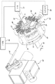
도 1은 일 실시예에 따른 온도 모니터링 시스템을 개략적으로 도시한 일부 등측도(partial isometric view)이다.
도 2는 명료함을 위하여 일부 구성요소가 제거된 도 1의 온도 모니터링 시스템의 전면 입면도(front elevational view)이다.
도 3은 3-3 선을 따라 도시된 도 1의 온도 모니터링 시스템의 단면도이다.
도 4는 명료함을 위하여 일부 구성요소가 제거된 도 1의 온도 모니터링 시스템의 전면 입면도이다.
도 5는 명료함을 위하여 일부 구성요소가 제거된 도 1의 온도 모니터링 시스템의 평면 입면도(top elevational view)이다.
도 6은 일 실시예에 따른 온도 모니터링 시스템의 구성요소의 기능적 블록도이다.
도 7은 다른 실시예에 따른 온도 모니터링 시스템의 일부 등측도이다.
도 8은 온도 모니터링 시스템의 일 실시예에 따른 모니터링 동안 자기 드라이브 시스템의 온도를 나타내는 그래프이다.
도 9는 온도 모니터링 시스템의 일 실시예에 따른 모니터링 동안 자기 드라이브 시스템의 온도를 나타내는 그래프이다. Figure 1 is a partial isometric view that schematically illustrates a temperature monitoring system in accordance with one embodiment.
Figure 2 is a front elevational view of the temperature monitoring system of Figure 1 with some components removed for clarity.
3 is a cross-sectional view of the temperature monitoring system of Fig. 1 taken along line 3-3.
Figure 4 is a front elevational view of the temperature monitoring system of Figure 1 with some components removed for clarity.
Figure 5 is a top elevational view of the temperature monitoring system of Figure 1 with some components removed for clarity.
6 is a functional block diagram of components of a temperature monitoring system in accordance with one embodiment.
7 is a partial isometric view of a temperature monitoring system according to another embodiment.
Figure 8 is a graph showing the temperature of the magnetic drive system during monitoring according to one embodiment of the temperature monitoring system.
9 is a graph showing the temperature of the magnetic drive system during monitoring according to one embodiment of the temperature monitoring system.
이하의 상세한 설명은 자기 드라이브 시스템의 온도의 모니터링과 연관되어 사용하기 위한 장치, 시스템 및 방법에 관한 것이다. 설명 및 대응하는 도면은 이 분야의 통상의 기술자에게 이 통상의 기술자가 본 발명의 실시예를 제조하고 사용할 수 있도록 충분한 정보를 제공하고자 의도한 것이다. 그러나, 이러한 통상의 기술자는 이 전체 발명의 상세한 설명을 읽고 도면을 검토한 후에, 본 발명의 정신으로부터 벗어나지 않고, 예시되고 기재된 실시예에 대해 변경이 이루어질 수 있고 및/또한 구성요소가 제거될 수 있음을 이해할 것이다. 모든 그러한 변경 및 벗어남은, 연관된 청구범위의 범위 내에 있는 한, 본 발명의 범위에 속하는 것으로 의도된다.The following detailed description relates to an apparatus, system and method for use in connection with monitoring the temperature of a magnetic drive system. The description and corresponding figures are intended to provide those of ordinary skill in the art with sufficient information to enable those skilled in the art to make and use the embodiments of the present invention. However, it will be apparent to those of ordinary skill in the art, after reading and understanding the details of this entire invention, that modifications can be made to the illustrated and described embodiments without departing from the spirit of the invention, and / . All such modifications and variations are intended to be within the scope of this invention as long as they are within the scope of the associated claims.
문맥이 달리 요구하지 않는 한, 명세서 및 이어지는 청구범위를 통해, "포함하다(comprise)" 단어 및 "포함하다(comprises)" 및 "포함하는(comprising)"과 같은 그 변형(variations)들은 개방되고, 포괄적인 의미, 즉 "포함(including)하지만, 이에 제한되지 않는"으로 해석된다.Unless the context requires otherwise, throughout the specification and the claims which follow, the word " comprise "and variations thereof such as " comprises" and " , &Quot; and " including, but not limited to, "
명세서 전체에 걸쳐 "일 실시예" 또는 "실시예"에 대한 참조는 그 실시예와 관련되어 기재된 특유의 특징(feature), 구조 또는 특질(characteristic)이 적어도 하나의 실시예에 포함되는 것을 의미한다. 따라서, 명세서 전체에 걸쳐 다양한 위치에서 "일 실시예에서" 또는 "실시예에서" 어구의 출현은 모두가 반드시 동일한 실시예를 참조하는 것은 아니다. 또한, 특유의 특징, 구조 또는 특질은 하나 또는 그 이상의 실시예에서 임의의 적합한 방식으로 결합될 수 있다. Reference throughout the specification to "one embodiment" or "an embodiment " means that a particular feature, structure, or characteristic described in connection with the embodiment is included in at least one embodiment . Thus, the appearances of the phrases "in one embodiment" or "in an embodiment" in various places throughout the specification are not necessarily all referring to the same embodiment. Moreover, the particular features, structures, or characteristics may be combined in any suitable manner in one or more embodiments.
이 명세서 및 첨부된 청구범위에서 사용되는 바에 따르면, 단수 형태 "하나(a, an)", "그(the)"는 내용이 명백하게 달리 기재하고 있지 않은 한 복수의 지시대상을 포함한다. 또한 용어 "또는(or)"은 일반적으로 내용이 명백하게 달리 기재하고 있지 않은 한 "및/또는(and/or)"을 의미하는 것임을 유의하여야 한다. As used in this specification and the appended claims, the singular forms "a," "an," and "the" include plural referents unless the context clearly dictates otherwise. It should also be noted that the term "or" generally means "and / or ", unless the context clearly dictates otherwise.
도 1-5는, 일 실시예에 따른, 자기 드라이브 시스템(12)의 온도를 유리하게 연속적으로 및 풍부하게(redundantly) 모니터링하는 온도 모니터링 시스템(10)을 나타낸다. 자기 드라이브 시스템(12)은 마그네틱 로터 어셈블리(14)와 컨덕터 로터 어셈블리(16)를 포함한다. 마그네틱 로터 어셈블리(14)는 한 쌍의 마그넷 로터(18)를 포함한다. 마그넷 로터(18)는 서로 간격을 두고 떨어져 있으며, 하나의 마그넷 로터(18)는 부하 샤프트(20) 가까이에 위치하고 다른 하나는 모터 샤프트(22) 가까이에 위치한다. 각 마그넷 로터(18)는 지지 디스크(backing disc)(26)(예를 들면, 철 지지 디스크)에 의해 지지되는 마그넷 디스크(24)(예를 들면, 비철 마그넷 디스크)를 포함한다. 마그넷 로터(18)는 부하 샤프트(20) 상에 장착되며 이와 함께 회전한다. 도 2에 가장 잘 도시된 바와 같이 각 마그넷 로터(18)의 마그넷 디스크(24)의 각각은 각 영구 자석(21)을 수용하기 위한 사각 포켓의 원형 어레이(19)를 다수 포함하고 있다. 1-5 illustrate a
컨덕터 로터 어셈블리(16)는 모터(13)의 모터 샤프트(22) 상에 장착되며, 이와 함께 회전한다. 컨덕터 로터 어셈블리(16)는 스페이서(32)에 의해 서로 간격을 두고 떨어져 있는 한 쌍의 컨덕터 로터(30)를 포함한다. 각 컨덕터 로터(30)는 단부 링(34)을 포함한다. 단부 링(34)의 안쪽으로 면한 측에 컨덕터 링(36, 37)이 연결되어 있다. 컨덕터 링(36, 37)은 일반적으로 구리, 알루미늄, 놋쇠, 또는 다른 비철 금속과 같은 비철 재료를 포함한다. 컨덕터 링(36, 37)은 에어 갭(38)에 의해 각 마그넷 로터(18)로부터 간격을 두고 떨어져 있다. 에어 갭(38)은 고정 에어 갭(예를 들면, 도 7)일 수 있으며, 또는 조정할 수 있는 에어 갭일 수 있다. 예를 들자면, 일부 자기 드라이브 시스템(12)은 액추에이터 어셈블리(actuator assembly)(39)를 포함할 수 있다. 액추에이터 어셈블리(39)는 공지의 방식으로 마그네틱 로터 어셈블리(14)에 연결된다. 액추에이터 어셈블리(39)는 자기 드라이브 시스템(12)의 에어 갭(38)이 조정 가능하도록 마그넷 로터 어셈블리(14)를 컨덕터 로터 어셈블리(16)에 대해 제어 가능하게 이동시키도록 구성된다. 또한, 도 1-5에 도시된 실시예에서는, 컨덕터 로터 어셈블리(16)가 모터 샤프트(22) 상에 장착되고 마그네틱 로터 어셈블리(14)는 부하 샤프트(20) 상에 장착되지만, 대안적으로, 컨덕터 로터 어셈블리(16)가 부하 샤프트(20) 상에 장착될 수 있으며 마그네틱 로터 어셈블리(18)가 모터 샤프트(22) 상에 장착될 수 있다. 이 방법에서는, 컨덕터 로터(30)가 부하 샤프트(20)와 함께 회전할 수 있으며 마그넷 로터(18)가 모터 샤프트(22)와 함께 회전할 수 있다.The
자기 드라이브 시스템(12)은 컨덕터 로터 어셈블리(16)의 바깥쪽으로 면하는 측에 연결된 히트싱크 요소(40)를 더 포함한다. 히트싱크 요소(40)는 잠금(fastening), 용접, 부착, 또는 다른 적절한 수단에 의해 컨덕터 로터 어셈블리(16에) 연결될 수 있다.The
위에서 지적한 바와 같이, 자기 드라이브 시스템은 일반적으로 슬립의 원리 하에서 작동한다. 컨덕터 재료 내의 전기적 와류는 그 내부에 전기적 가열을 발생시킨다. 렌츠의 법칙(Lenz's Law)을 이용하면, 발생하는 열의 양은 다음과 같이 계산될 수 있다: 슬립 열 = K * 토크 * 슬립 속도, 이는 결과적으로: k * τ * (ωM - ωL)가 된다. 여기에서 τ는 모터 토크; ωM는 분당 회전수("RPM")로 나타낸 모터 속도; ωL 는 RPM으로 나타낸 출력 속도이며; k는 샤프트 파워를 KW 또는 선택된 임의의 다른 전력 단위로 변환하는 상수이다. 특히, 자기 드라이브 시스템에 의해 발생되는 열이 추정될 때, 이러한 계산은 외부 조건 및 작동 환경을 고려하지 않으며, 이러한 계산은 가장 높은 양의 열이 발생되는 정확한 위치를 고려하지도 않는다. As noted above, magnetic drive systems generally operate under the principle of slip. The electrical vortex in the conductor material causes electrical heating within it. Using Lenz's Law, the amount of heat generated can be calculated as: slip heat = K * torque * slip velocity, which results in: k * τ * (ω M - ω L ) . Where τ is the motor torque; ω M is the motor speed in revolutions per minute ("RPM"); ? L is the output speed in RPM; k is a constant that converts the shaft power to KW or any other selected power unit. In particular, when the heat generated by the magnetic drive system is estimated, such calculations do not take into account external conditions and operating conditions, and such calculations do not take into account the exact position at which the highest amount of heat is generated.
온도 모니터링 시스템(10) 및 여기에서 기재된 다른 실시예들은 자기 드라이브 시스템을 유리하게 연속적으로 풍부하게 모니터링하며 측정된 온도에 응답하여 적절한 명령을 제공한다. 도 1-5를 계속 참조하여, 그리고 도 4-5에서 가장 잘 나타난 바와 같이, 온도 모니터링 시스템(10)은 다수의 온도 센서(42)를 포함한다. 온도 센서(42)는 열전쌍(thermocouples), 서미스터(thermistors), 측온 저항체(resistance temperature detector, RTD), 및/또는 다른 온도 감지 장치를 포함할 수 있다. 비제한적인 예로서, 도 1-5에 도시된 온도 모니터링 시스템(10)은 열전쌍을 포함한다. 그러나, 다른 온도 감지 장치들이 본 개시의 범위 내이다. 온도 센서(42)는 자기 드라이브 시스템(12) 상에 장착된 송신기(44)에 연결된다. 송신기(44)는 히트싱크 요소(40) 위에 가로놓이며 잠금 장치(fasteners)를 통해 각 단부 링(34)에 연결된다. 다른 실시예에서, 송신기(44)는 임의의 다른 적합한 위치에 배치될 수 있으며, 및/또는 자기 드라이브 시스템(12)으로부터 원격으로 위치될 수도 있다. 송신기(44)는 각 온도 센서(42)를 수용하도록 구성된 다수의 입력 커넥터를 포함한다. 예시적으로, 도 1-5에 도시된 송신기(44)는 6개의 입력 커넥터를 포함한다. 6개의 입력 커넥터 각각은 일반적으로 서로 분리된 6개의 채널을 정의하며, 온도 센서(42)의 각 근단부에 연결되도록 구성된다. 그러나, 송신기(44)가 임의의 수의 입력 커넥터를 포함할 수 있음을 이해할 것이다. 또한, 입력 커넥터는, 예를 들면 J, K, N, R 유형의 열전쌍과 같은 다양한 종류의 온도 센서를 수용하도록 구성될 수 있다. The
각 온도 센서(42)(예를 들면, 42a, 42b, 42c, 42d)의 원단부(46)는, 온도 센서(42)가 열전쌍을 포함할 때 일반적으로 온접점(hot junction)으로 지칭되는, 자기 드라이브 시스템(12) 상의 온도가 측정되는 위치에 연결된다. 도 4-5에 가장 잘 나타난 바와 같이, 온도 센서(42a, 42b, 42c, 42d)의 원단부(46)는 컨덕터 링(36, 37)에 연결된다. 원단부(46)는 납땜, 부착, 잠금, 또는 다른 적절한 수단을 통해 컨덕터 링(36, 37)에 연결될 수 있다. The
더 구체적으로, 각 센서(42a, 42b)의 원단부(46)는 자기 드라이브 시스템(12)의 모터(13) 측 상에 위치한 컨덕터 링(36)의 두께를 통해 실질적으로 가운데로 연장된다. 또한, 원단부(46)는 실질적으로 마그네틱 중심선(47)을 따라 배치된다. 도 2 및 3에 가장 잘 나타나 있는 바와 같이, 마그네틱 중심선(47)은 각 마그넷 로터 디스크(24)의 영구 자석(21)의 중심선에 의해 정의되는 경로를 원주 방향으로 따르는 동축 링에 의해 정의되며, 컨덕터 링(36, 37) 위로 투영된다. 유사하게, 각 센서(42c, 42d)의 원단부(46)는 컨덕터 링(36)(즉, 부하 측)의 두께를 통해 실질적으로 가운데로 실질적으로 마그네틱 중심선(47)을 따라 연장된다. 이런 방식으로 원단부(46)를 배치하는 것은, 이러한 위치가 자기 드라이브 시스템(12)의 가장 높은 온도의 위치를 나타내므로, 자기 드라이브 시스템(12)의 온도 판독의 정확성을 유리하개 개선함을 출원인은 실험을 통해 발견하였다. 도 1-5의 실시예에서 예시된 온도 센서(42)는 컨덕터 링(36, 37) 내에 위치하지만, 다른 실시예에서는, 온도 센서(42)가 임의의 다른 적절한 위치에 위치할 수 있다. More specifically, the
도 1-5를 계속 참조하면, 온도 모니터링 시스템(10)은 기준 온도를 측정하기 위하여 추가의 온도 센서(42)를 포함할 수 있다. 예시적으로, 추가 온도 센서의 원단부는 자기 드라이브 시스템(12)의 다른 구성요소에 연결되어 기준 온도의 측정을 제공할 수 있다. 원단부는, 예를 들면, 마그넷 로터(18)의 각 지지 디스크(26) 또는 최소의 열 발생을 경험할 수 있는 다른 구성요소에 연결될 수 있다. 온도 모니터링 시스템(10)은 주위 온도를 측정하여 컨덕터 로터(30)의 온도를 주위 온도에 대해 수립하고 비교할 수 있다. 이 방법에서는, 온도 모니터링 시스템(10)은 주위 온도를 실시간으로 계속하여 측정하고 모니터링할 수 있으며, 이에 따라 정확한 판독을 유리하게 제공하고 자기 드라이브 시스템의 가변적인 작동 환경의 불확실성을 또한 고려할 수 있다.1-5, the
온도 센서(42)에 의해 측정된 다양한 온도는, 예를 들면, 온도 센서(42)가 열전쌍을 포함할 때. 냉접점(cold junction)과 온접점(hot junction) 사이의 온도차의 열 경사(thermal gradient)를 나타내는 입력 전압 신호를 제공할 수 있다. 선택적으로, 온도 센서(42)가 RTD를 포함할 때, 저항 신호가 제공될 수 있다. 이 방법에서는, 송신기(44)가 각 신호를 처리하여 온도를 결정하고 상응하는 신호를 출력할 수 있다. The various temperatures measured by the
송신기(44)는 또한 송수신기(48)에 연결된다. 송신기(44)는 도 1-5의 실시예에 도시된 바와 같이, 무선으로 송수신기(48)에 연결될 수 있으며, 또는 공지의 방식으로 유선 연결을 통해 연결될 수 있다.The
송수신기(48)는 송신기(44)와 전기적으로 통신할 수 있도록 구성되며, 송수신기(48)가 온도 센서(42)의 온도 측정값을 제어기(50)로 통신할 수 있도록 하기 위하여, 제어기(50)와 송신기(44) 사이의 인터페이스를 제공한다. 송수신기(48)는 무선으로 제어기(50)에 연결되거나, 또는 도 1-5의 실시예에서 도시된 바와 같이, USB 케이블과 같은 유선 연결을 통해 연결될 수 있다. 제어기(50)는, 제한 없이, 하나 또는 그 이상의 프로세서, 마이크로프로세서, 디지털 신호 처리기(digital signal processors: DSPs), 현장 프로그램 가능 게이트 어레이(field programmable gate array: FGPA), 및/또는 주문형 집적회로(application-specific integrated circuits: ASICs), 메모리 장치, 버스, 전력원 등을 포함할 수 있다. 예를 들면, 제어기(50)는 하나 또는 그 이상의 메모리 장치와 통신하는 프로세서를 포함할 수 있다. 버스는 내부 또는 외부 전원을 프로세서에 연결할 수 있다. 메모리는, 예를 들면, 하나 또는 그 이상의 버퍼, 레지스터, 임의 접근 메모리(RAMs), 및/또는 읽기 전용 메모리(ROMs)를 포함하는 다양한 형태를 취할 수 있다. 일부 실시예에서, 제어기(50)는 컴퓨터(예를 들면, 데스크탑 컴퓨터, 랩탑 컴퓨터, 등), 네트워크(예를 들면, 로컬 네트워크, WiFi 네트워크, 등), 또는 모바일 장치(예를 들면, 스마트폰, 셀룰러폰, 등)와 같은 외부 장치 또는 시스템과 통신할 수 있도록 연결될 수 있다. 제어기(50)는 또한, 화면과 같은 디스플레이, 및 입력 장치를 포함할 수 있다. 입력 장치는 키보드, 터치패드 등을 포함할 수 있으며 온도 모니터링 시스템(10)을 제어하기 위하여 사용자에 의해 조작될 수 있다.The
일부 실시예에서, 제어기(50)는 폐루프 시스템(closed loop system) 또는 개루프 시스템(open loop system)을 갖는다. 예를 들면, 제어기(50)는 폐루프 시스템을 가질 수 있으며, 모터(13) 및 결과적으로 모터 샤프트(22)로의 파워가 하나 또는 그 이상의 온도 특성 또는 임의의 다른 측정가능한 관심 파라미터를 나타내는 하나 또는 그 이상의 신호를 송신(또는 전송)하도록 구성된 하나 또는 그 이상의 온도 센서(42)로부터의 피드백 신호에 기반하여 제어된다. 이후 이러한 판독에 기반하여, 제어기(50)는 모터(13)의 작동을 조정할 수 있다. 일부 실시예에서, 제어기(50)의 폐루프 시스템은 하나 또는 그 이상의 온도 특성 또는 임의의 다른 측정가능한 관심 파라미터를 나타내는 하나 또는 그 이상의 신호를 송신(또는 전송)하도록 구성된 하나 또는 그 이상의 온도 센서(42)로부터의 피드백 신호에 기반하여 추가적으로 및/또는 대안적으로 액추에이터 어셈블리(39) 및 결과적으로 에어 갭(38)을 제어하도록 구성될 수 있다. 이러한 판독에 기반하여, 제어기(50)는 이제 액추에이터 어셈블리(39)의 작동을 조정할 수 있다. 선택적으로, 온도 모니터링 시스템(10)은 모터(13) 및/또는 액추에이터 어셈블리(39)의 작동이 사용자 입력에 의하여 설정되는 개루프 시스템일 수 있다. In some embodiments, the
추가로, 제어기(50)는 다른 프로그램을 저장할 수 있다. 사용자는 원하는 목표 온도 문턱값과 온도의 특성을 고려하는 프로그램을 선택할 수 있다. 예를 들자면, 온도 문턱값은 특정한 자기 드라이브 시스템 및/또는 특정한 모터 기반으로 설정될 수 있다. 제어기(50)는 모터가 막힐(jammed) 때를 포함하여, 모터 속도 및 자기 드라이브 시스템의 최대 토크에 기반하여 문턱 온도(threshold temperature)를 결정하는 프로그램을 실행할 수 있다. 일부 실시예에서, 문턱 온도는 다음의 식 기반으로 설정된다:In addition, the

여기에서 ![]()
![]()
제어기(50)는 다양한 온도 센서의 온도 측정치를 문턱 온도와 비교하도록 프로그램될 수 있다. 예를 들자면, 제어기(50)는 다양한 온도 센서(42)의 온도를 결정하기 위하여 송수신기(48)를 계속해서 스캔하도록 하는 프로그램을 실행할 수 있다. 제어기(50)는 온도 측정치가 문턱 온도 또는 문턱 온도의 선택된 백분율을 넘을 때 모터(13)로의 전원공급을 억제하거나 제거하도록 모터 작동 프로그램을 실행할 수 있다. 제어기(50)는 또한 마그넷 로터 어셈블리(14)와 컨덕터 로터 어셈블리(16) 사이의 에어 갭(38)을 제어하도록 프로그램될 수 있다. 에어 갭((38)은 액추에이터 어셈블리(39), 또는 임의의 다른 장치에 의한 마그넷 로터(18)와 컨덕터 로터(30)의 상대 운동에 의해 조정될 수 있다. The
도 6은 온도 모니터링 시스템의 사용을 보여주는 기능적 블록도를 나타낸다. 온도 모니터링 시스템은 적어도 감지 모듈(51), 제어 모듈(52), 및 응답 모듈(56, 58)을 포함한다. 감지 모듈(51)은 자기 드라이브 시스템(12)에 연결된 다수의 온도 센서(42)를 포함한다. 온도 센서(42)는 각 온도 센서(42)의 온도를 결정하기 위하여 상응하는 신호를 처리하는 송신기(44)에 통신할 수 있도록 연결된다. 송신기(44)는 또한 송수신기(48)에 연결된다. 다른 곳에서 더 자세히 논의된 바와 같이, 송신기(44)는 무선 또는 유선 연결을 통해 송수신기(48)에 연결될 수 있다. 이 방법에서는, 송수신기(48)는 송신기(44)로부터 자기 드라이브 시스템(12)의 온도를 나타내는 하나 또는 그 이상의 신호를 수신한다.Figure 6 shows a functional block diagram illustrating the use of a temperature monitoring system. The temperature monitoring system includes at least a
제어 모듈(52)은 제어기(50)를 포함한다. 제어기(50)는 송수신기(48)에 연결되며 송수신기(48)와 통신한다. 제어기(50)의 프로세서 및 제어 회로는 송수신기(48)로부터 자기 드라이브 시스템(12) 상에 장착된 온도 센서(42)의 온도를 나타내는 신호를 수신한다. 프로세서는 자기 드라이브 시스템(12)의 온도의 비교를 수행하기 위하여 정보를 사용한다. 더 구체적으로, 프로세서는 다수의 온도 센서(42)에 의해 나타나는 자기 드라이브 시스템(12)의 온도를 설정된 문턱 온도와 비교한다. The control module 52 includes a
온도가 문턱 온도를 넘거나, 응답 모듈(56) 하에서 신호가 수신되지 않으면, 제어기(50)는 상응하는 출력 신호를 전송함으로써 모터(13)의 작동을 중단하도록 하나 또는 그 이상의 모터(13) 구성요소에 명령한다. 모터(13)는 전원을 제거하거나 모터의 특정한 구성요소를 푸는(disengage) 등의 다양한 방법으로 작동이 중단될 수 있다. 반대로, 온도가 문턱 온도보다 낮고 신호가 수신되면, 제어기(50)는 모터(13)의 하나 또는 그 이상의 구성요소로 작동을 계속하도록 명령하고, 이어서, 부하(60)를 구동하기 위한 회전력을 전달한다. 이 방법에서는, 자기 드라이브 시스템의 온도는 유리하게 계속적으로 모니터링될 수 있으며, 온도가 설정된 문턱값을 넘을 때, 예를 들면, 막히는 경우(jam), 온도 모니터링 시스템(10)은 모터(13)의 작동을 중단시켜서 자기 드라이브 시스템(12)의 과열을 방지한다.If the temperature exceeds the threshold temperature or the signal is not received under the
대안적으로 또는 추가적으로, 온도가 문턱 온도를 넘고 및/또는 응답 모듈(58) 하에서 신호가 수신되지 않으면, 제어기(50)는 상응하는 출력 신호를 전송함으로써 액추에이터 어셈블리(39)의 하나 또는 그 이상의 구성요소에 자기 드라이브 시스템(12)의 에어 갭(38)을 조정하도록 명령한다. 더 구체적으로, 제어기(50)는 마그넷 로터(18)를 컨덕터 로터(30)에 대해 최대 에어 갭 위치까지 축 방향으로 움직이도록 액추에이터 어셈블리(39)에 명령한다. 이 방법에서는, 마그넷 로터(18)와 컨덕터 로터(30) 사이의 회전력이 실질적으로 제거될 수 있으며, 이에 따라, 자기 드라이브 시스템(12)을 유리하게 작동 중지시키고 그 과열을 방지한다. Alternatively or additionally, if the temperature is above the threshold temperature and / or no signal is received under the
도 7은 다른 실시예에 따른 온도 모니터링 시스템(110)을 도시한다. 온도 모니터링 시스템(110)은 마그넷 로터 어셈블리(114)가 컨덕터 로터 어셈블리(116)에 대해 고정적으로 위치하는 변화를 제공한다. 이에 따라, 제어기(150)는 자기 드라이브 시스템(112)의 온도가 설정된 문턱 온도보다 낮거나 온도 센서(142)로부터 피드백 신호가 수신될 때 모터(113)의 하나 또는 그 이상의 구성요소에 작동을 계속하도록 명령하도록 구성된다. 반대로, 제어기(150)는 온도가 문턱 온도를 넘을 때 및/또는 온도 센서(142) 중 어느 것으로부터도 피드백 신호가 수신되지 않을 때 모터(113)의 하나 또는 그 이상의 구성요소에 작동을 중지하도록 명령하도록 구성된다. FIG. 7 illustrates a
도 8은 온도 모니터링 시스템의 일 실시예에 따라 측정된 온도에 상응하는 세로축의 그래프이다. 온도 모니터링 시스템은 조정할 수 있는 에어 갭을 갖는 자기 드라이브 시스템과 연결되어 사용된다. 도 8에 도시된 바와 같이, 온도 트리거(trigger)가 온도 문턱값의 약 80%로 설정되었다. 온도 센서(즉, 열전쌍(23))가 설정된 문턱 온도에 도달할 때, 제어 모듈이 모터로의 전원을 제거함에 의해 모터를 작동 중지하는 출력 신호를 보냈다. 짧은 지연 후에, 모터 속도가 감소함에 따라 온도가 내려갔다.Figure 8 is a graph of the vertical axis corresponding to the temperature measured in accordance with one embodiment of the temperature monitoring system. The temperature monitoring system is used in conjunction with a magnetic drive system with adjustable air gaps. As shown in Figure 8, the temperature trigger was set at about 80% of the temperature threshold. When the temperature sensor (i.e., thermocouple 23) reaches the set threshold temperature, the control module sends an output signal to shut down the motor by removing power to the motor. After a short delay, the temperature dropped as the motor speed decreased.
도 9는 온도 모니터링 시스템의 일 실시예에 따라 측정된 온도에 상응하는 세로축의 그래프이다. 온도 모니터링 시스템은 고정된 에어 갭을 갖는 자기 드라이브 시스템과 연결되어 사용된다. 도 9에 도시된 바와 같이, 온도 트리거가 온도 문턱값의 약 80%로 설정되었다. 온도 센서(즉, 열전쌍(1))가 설정된 문턱 온도에 도달할 때, 제어 모듈이 모터로의 전원을 제거함에 의해 모터를 작동 중지하는 출력 신호를 보냈다. 다시, 짧은 지연 후에, 모터 속도가 감소함에 따라 온도가 내려갔다.Figure 9 is a graph of the vertical axis corresponding to the temperature measured in accordance with one embodiment of the temperature monitoring system. The temperature monitoring system is used in conjunction with a magnetic drive system with a fixed air gap. As shown in FIG. 9, the temperature trigger was set at about 80% of the temperature threshold. When the temperature sensor (i.e., thermocouple 1) reaches the set threshold temperature, the control module sends an output signal to shut down the motor by removing power to the motor. Again, after a short delay, the temperature dropped as the motor speed decreased.
상술한 다양한 실시예는 자기 드라이브 시스템을 연속적으로 및 풍부하게 모니터링하는 방법을 유리하게 제공할 수 있다. 예를 들자면, 자기 드라이브 시스템의 모니터링 방법은 하나 또는 그 이상의 온도 센서를 자기 드라이브 시스템에 연결하는 단계를 포함할 수 있다. 온도 센서는 송신기에 연결되어 온도에 상응하는 적절한 신호를 처리할 수 있다. The various embodiments described above can advantageously provide a method for continuous and abundant monitoring of a magnetic drive system. For example, a method of monitoring a magnetic drive system may include connecting one or more temperature sensors to the magnetic drive system. The temperature sensor can be connected to the transmitter to process the appropriate signal corresponding to the temperature.
방법은 송수신기를 송신기에 그리고 제어기에 통신할 수 있게 연결하는 단계를 포함할 수 있으며, 송수신기는 자기 드라이브 시스템의 온도를 제어기로 통신한다. 방법은 문턱 온도를 설정하는 단계, 온도를 설정된 문턱 온도와 비교하는 단계, 및 비교에 응답하여 출력 신호를 전송하는 단계를 더 포함할 수 있다. 일부 실시예에서, 출력 신호는 온도가 문턱 온도보다 낮을 때와 제어기에 의해 피드백 신호가 수신될 때 자기 드라이브 시스템에 연결된 모터로 작동을 계속하도록 하는 명령을 표시할 수 있다. 일부 실시예에서, 출력 신호는 온도가 문턱 온도 이상일 때 모터의 작동을 중단하도록 하는 것을 표시할 수 있다. 일부 실시예에서, 출력 신호는 자기 드라이브 시스템을 최대 에어 갭 위치로 배치하도록 액추에이터에 명령하는 것을 표시할 수 있다. The method can include communicating the transceiver to the transmitter and to the controller in a communicative manner, wherein the transceiver communicates the temperature of the magnetic drive system to the controller. The method may further include setting a threshold temperature, comparing the temperature to a set threshold temperature, and transmitting the output signal in response to the comparison. In some embodiments, the output signal may indicate an instruction to continue operating with the motor connected to the magnetic drive system when the temperature is below the threshold temperature and when the feedback signal is received by the controller. In some embodiments, the output signal may indicate to cause the motor to stop operating when the temperature is above the threshold temperature. In some embodiments, the output signal may indicate commanding the actuator to position the magnetic drive system at a maximum air gap position.
방법은 표시기를 제어기에 연결하는 단계를 더 포함할 수 있다. 표시기는 온도가 문턱 온도를 넘을 때 및/또는 제어기에 의해 피드백 신호가 수신되지 않을 때 사용자에게 통신하도록 구성될 수 있다. 표시기는 가청 알람(audible alarm), 버저(buzzer), 게이지(gauge), 및/또는 발광 다이오드(light emitting diode, LED) 를 포함할 수 있다.The method may further comprise connecting the indicator to the controller. The indicator may be configured to communicate to the user when the temperature exceeds the threshold temperature and / or when the feedback signal is not received by the controller. The indicator may include an audible alarm, a buzzer, a gauge, and / or a light emitting diode (LED).
또한, 위에서 기재된 다양한 실시예가 추가 실시예를 제공하기 위하여 결합될 수 있다. 이들 및 다른 변화가 상술한 발명의 상세한 설명의 관점에서 실시예에 이루어질 수 있다. 일반적으로, 이하의 청구범위에서, 사용된 용어는 청구범위를 명세서 및 청구범위에 개시된 특정한 실시예에 한정하는 것으로 해석되어서는 안되며, 이러한 청구범위의 권리가 있는 모든 범위의 균등물과 함께 모든 가능한 실시예를 포함하는 것으로 해석되어야 한다. 따라서, 청구범위는 이 개시에 의해 제한되지 않는다.In addition, various embodiments described above may be combined to provide further embodiments. These and other changes may be made to the embodiments in light of the above detailed description of the invention. In general, in the following claims, the terms used should not be construed as limiting the claim to the specific embodiments disclosed in the specification and the claims, and all possible equivalents Which should be construed as including embodiments. Accordingly, the claims are not limited by this disclosure.
Claims (25)
상기 자기 드라이브 시스템 상에 장착되는 온도 센서;
상기 온도 센서에 연결되어 있으며, 상기 온도 센서의 온도를 나타내는 신호를 발생시키는 송신기;
상기 송신기에 연결되어 있으며, 상기 신호를 수신하도록 구성되는 송수신기; 및
상기 송수신기 및 상기 자기 드라이브 시스템과 통신할 수 있도록 연결되며(communicatively coupled), 상기 송수신기로부터 수신되는 하나 또는 그 이상의 신호에 기반하여 상기 자기 드라이브 시스템의 작동을 제어하도록 구성되는 제어기를 포함하는,
온도 모니터링 시스템.1. A temperature monitoring system for a magnetic drive system,
A temperature sensor mounted on the magnetic drive system;
A transmitter, coupled to the temperature sensor, for generating a signal indicative of the temperature of the temperature sensor;
A transceiver coupled to the transmitter and configured to receive the signal; And
A controller communicatively coupled to the transceiver and the magnetic drive system and configured to control operation of the magnetic drive system based on one or more signals received from the transceiver,
Temperature monitoring system.
상기 제어기는 상기 온도를 문턱 온도와 비교하고 상기 온도와 상기 문턱 온도의 비교에 응답하여 상기 자기 드라이브 시스템에 명령하도록 구성되는,
온도 모니터링 시스템.The method according to claim 1,
Wherein the controller is configured to compare the temperature to a threshold temperature and to command the magnetic drive system in response to a comparison of the temperature and the threshold temperature,
Temperature monitoring system.
상기 제어기는 상기 온도가 상기 문턱 온도를 넘을 때 상기 자기 드라이브 시스템으로 셧다운(shutdown) 신호를 출력하도록 구성되는,
온도 모니터링 시스템.3. The method of claim 2,
Wherein the controller is configured to output a shutdown signal to the magnetic drive system when the temperature exceeds the threshold temperature.
Temperature monitoring system.
상기 제어기는 상기 송수신기에 의해 출력 신호가 수신되지 않을 때 상기 자기 드라이브 시스템으로 셧다운 신호를 출력하도록 구성되는,
온도 모니터링 시스템.3. The method of claim 2,
Wherein the controller is configured to output a shutdown signal to the magnetic drive system when an output signal is not received by the transceiver,
Temperature monitoring system.
다수의 열전쌍(thermocouples)을 더 포함하며,
상기 다수의 열전쌍은 상기 자기 드라이브 시스템의 컨덕터 로터(conductor rotor) 상에 장착되고,
상기 다수의 열전쌍은 실질적으로 마그네틱 중심선(magnetic centerline)을 따라 장착되는,
온도 모니터링 시스템.The method according to claim 1,
Further comprising a plurality of thermocouples,
Wherein the plurality of thermocouples are mounted on a conductor rotor of the magnetic drive system,
Wherein the plurality of thermocouples are mounted substantially along a magnetic centerline,
Temperature monitoring system.
상기 문턱 온도는 미리 정의된 온도 한계의 80%로 설정되는,
온도 모니터링 시스템.3. The method of claim 2,
Wherein the threshold temperature is set to 80% of a predefined temperature limit,
Temperature monitoring system.
부하 샤프트(load shaft)에 연결된 마그네틱 로터 어셈블리(magnetic rotor assembly)로서, 상기 마그네틱 로터 어셈블리는 한 쌍의 마그넷 로터를 포함하고, 각 마그넷 로터는 각자 자석 세트를 포함하고, 상기 마그넷 로터는 상기 한 쌍의 동축 컨덕터 로터 사이에 위치하며 에어 갭을 정의하기 위하여 상기 컨덕터 로터로부터 간격을 두고 떨어져 있는, 상기 마그네틱 로터 어셈블리를 포함하는 자기 드라이브 시스템;
상기 컨덕터 로터 상에 장착된 다수의 열전쌍;
상기 다수의 열전쌍에 연결되며, 각 열전쌍의 온접점(hot juncture)의 온도를 나타내는 신호를 발생하도록 구성된 열전쌍 송신기;
상기 열전쌍 송신기와 통신할 수 있도록 연결되며, 상응하는 신호를 수신하도록 구성된 송수신기; 및
상기 송수신기 및 상기 자기 드라이브 시스템에 통신할 수 있도록 연결되며, 각 열전쌍의 온도에 대해 상기 송수신기를 연속적으로 스캔할 수 있도록 구성된 제어기를 포함하는,
온도 모니터링 시스템.A conductor rotor assembly connected to a motor shaft, the conductor rotor assembly comprising a pair of coaxial conductor rotors, the conductor rotor comprising a non-ferrous electroconductive material, said conductor rotor assembly having a body of material,
A magnetic rotor assembly coupled to a load shaft, wherein the magnetic rotor assembly includes a pair of magnet rotors, each magnet rotor comprising a set of magnets each of which is coupled to the pair of magnets A magnetic drive system located between said coaxial conductor rotor and said magnetic rotor assembly spaced apart from said conductor rotor to define an air gap;
A plurality of thermocouples mounted on the conductor rotor;
A thermocouple transmitter coupled to the plurality of thermocouples, the thermocouple transmitter configured to generate a signal indicative of the temperature of the hot juncture of each thermocouple;
A transceiver coupled to communicate with the thermocouple transmitter and configured to receive a corresponding signal; And
And a controller coupled to the transceiver and the magnetic drive system for communicating with the transceiver and configured to continuously scan the transceiver for a temperature of each thermocouple.
Temperature monitoring system.
상기 송수신기는 상기 송신기에 무선 연결되는,
온도 모니터링 시스템.8. The method of claim 7,
Wherein the transceiver is wirelessly connected to the transmitter,
Temperature monitoring system.
상기 제어기는 상기 열전쌍의 온도를 문턱 온도와 비교하고 상기 온도와 상기 문턱 온도의 비교에 응답하여 상기 자기 드라이브 시스템에 명령하도록 구성되는,
온도 모니터링 시스템.8. The method of claim 7,
Wherein the controller is configured to compare the temperature of the thermocouple to a threshold temperature and to command the magnetic drive system in response to the comparison of the temperature and the threshold temperature,
Temperature monitoring system.
상기 제어기는 적어도 하나의 상기 열전쌍의 상기 온도가 상기 문턱 온도를 넘거나 상기 송수신기에 의해 상기 신호가 수신되지 않을 때 상기 자기 드라이브 시스템으로 셧다운 신호를 전송하도록 구성되는,
온도 모니터링 시스템.10. The method of claim 9,
Wherein the controller is configured to transmit a shutdown signal to the magnetic drive system when the temperature of the at least one thermocouple exceeds the threshold temperature or the signal is not received by the transceiver.
Temperature monitoring system.
상기 자기 드라이브 시스템은 상기 에어 갭을 조정하기 위하여 상기 마그넷 로터를 상기 컨덕터 로터에 대해 축 방향으로 이동시키도록 구성되는 액추에이터(actuator)를 더 포함하는,
온도 모니터링 시스템.10. The method of claim 9,
Wherein the magnetic drive system further comprises an actuator configured to axially move the magnet rotor relative to the conductor rotor to adjust the air gap,
Temperature monitoring system.
상기 제어기는 적어도 하나의 상기 열전쌍의 상기 온도가 상기 문턱 온도를 넘거나 상기 송수신기에 의해 상기 신호가 수신되지 않을 때 상기 자기 드라이브 시스템으로 셧다운 신호를 전송하도록 구성되는,
온도 모니터링 시스템.12. The method of claim 11,
Wherein the controller is configured to transmit a shutdown signal to the magnetic drive system when the temperature of the at least one thermocouple exceeds the threshold temperature or the signal is not received by the transceiver.
Temperature monitoring system.
상기 셧다운 신호는 상기 모터 샤프트를 구동하는 모터로의 전원을 제거하도록 상기 자기 드라이브 시스템에 명령하는,
온도 모니터링 시스템.13. The method of claim 12,
Wherein the shutdown signal instructs the magnetic drive system to remove power to the motor driving the motor shaft,
Temperature monitoring system.
상기 셧다운 신호는 상기 에어 갭이 최대 에어 갭 구성까지 증가하도록 상기 마그넷 로터를 상기 각 컨덕터 로터에 대해 이동시키도록 상기 액추에이터에 명령하는,
온도 모니터링 시스템.13. The method of claim 12,
Wherein the shutdown signal instructs the actuator to move the magnet rotor relative to the respective conductor rotor such that the air gap increases to a maximum air gap configuration,
Temperature monitoring system.
상기 온도를 문턱 온도와 비교하는 단계; 및
상기 비교에 응답하여 상기 자기 드라이브 시스템으로 신호를 전송하는 단계를 포함하는,
자기 드라이브 시스템의 온도 모니터링 방법.Measuring a temperature of the magnetic drive system;
Comparing the temperature to a threshold temperature; And
And transmitting a signal to the magnetic drive system in response to the comparison.
Method of monitoring the temperature of a magnetic drive system.
상기 온도를 측정하는 단계는,
송수신기에 연결된 송신기로부터 출력 신호를 발생시키는 단계를 포함하며,
상기 출력 신호는 상기 자기 드라이브 시스템에 연결된 온도 센서의 온도를 나타내는,
자기 드라이브 시스템의 온도 모니터링 방법.16. The method of claim 15,
Wherein the step of measuring the temperature comprises:
Generating an output signal from a transmitter coupled to the transceiver,
Wherein the output signal is indicative of a temperature of a temperature sensor connected to the magnetic drive system,
Method of monitoring the temperature of a magnetic drive system.
상기 온도를 비교하는 단계는,
제어기를 상기 자기 드라이브 시스템의 상기 온도를 나타내는 출력 신호를 수신하도록 구성되는 송수신기에 통신할 수 있게 연결하는 단계; 및
상기 자기 드라이브 시스템의 상기 온도를 상기 문턱 온도와 비교하기 위하여 상기 송수신기를 연속적으로 스캔하는 단계를 포함하는,
자기 드라이브 시스템의 온도 모니터링 방법.16. The method of claim 15,
Wherein comparing the temperatures comprises:
Communicatively coupling a controller to a transceiver configured to receive an output signal indicative of the temperature of the magnetic drive system; And
And continuously scanning the transceiver to compare the temperature of the magnetic drive system with the threshold temperature.
Method of monitoring the temperature of a magnetic drive system.
적어도 하나의 상기 온도가 상기 문턱 온도를 넘거나 상기 송수신기에 의해 출력 신호가 수신되지 않을 때 상기 자기 드라이브 시스템을 작동하지 않도록 하는 단계; 및
상기 온도가 상기 문턱 온도 이하이고 상기 송수신기에 의해 출력 신호가 수신될 때 상기 자기 드라이브 시스템의 작동을 계속하는 단계를 더 포함하는,
자기 드라이브 시스템의 온도 모니터링 방법.18. The method of claim 17,
Preventing the magnetic drive system from operating when at least one of the temperatures exceeds the threshold temperature or an output signal is not received by the transceiver; And
Further comprising: continuing operation of the magnetic drive system when the temperature is below the threshold temperature and an output signal is received by the transceiver.
Method of monitoring the temperature of a magnetic drive system.
상기 문턱 온도를 설정하는 단계를 더 포함하는,
자기 드라이브 시스템의 온도 모니터링 방법.16. The method of claim 15,
Further comprising the step of setting the threshold temperature,
Method of monitoring the temperature of a magnetic drive system.
상기 문턱 온도는 다음의 수식:
문턱 온도 = (허용 가능한 최대 온도) - 온도 증가/초*시스템 응답 시간
에 의해 결정되는,
자기 드라이브 시스템의 온도 모니터링 방법.20. The method of claim 19,
The threshold temperature may be calculated using the following equation:
Threshold temperature = (maximum allowable temperature) - Temperature increase / second * System response time
Lt; / RTI >
Method of monitoring the temperature of a magnetic drive system.
상기 신호를 송신하는 단계는,
상기 자기 드라이브 시스템에 연결된 모터의 전원을 제거하는 단계 및 상기 자기 드라이브 시스템의 상기 에어 갭을 최대 에어 갭으로 증가시키는 단계 중 적어도 하나를 포함하는,
자기 드라이브 시스템의 온도 모니터링 방법.16. The method of claim 15,
Wherein the transmitting the signal comprises:
Removing at least one of powering off the motor connected to the magnetic drive system and increasing the air gap of the magnetic drive system to a maximum air gap.
Method of monitoring the temperature of a magnetic drive system.
상기 온도를 측정하는 단계는,
다수의 열전쌍을 상기 자기 드라이브 시스템에 연결하는 단계;
상기 각 열전쌍에 상기 각 열전쌍의 온접점의 온도를 나타내는 신호를 발생시키는 송신기를 연결하는 단계;
상기 송신기에 상기 신호를 수신하도록 구성된 송수신기를 연결하는 단계를 포함하는,
자기 드라이브 시스템의 온도 모니터링 방법.16. The method of claim 15,
Wherein the step of measuring the temperature comprises:
Coupling a plurality of thermocouples to the magnetic drive system;
Connecting a transmitter to each of the thermocouples to generate a signal indicative of the temperature of the thermocouple's on-contact point;
And connecting a transceiver configured to receive the signal to the transmitter.
Method of monitoring the temperature of a magnetic drive system.
상기 다수의 열전쌍은 마그네틱 중심선을 따라 상기 자기 드라이브 시스템에 연결되는,
자기 드라이브 시스템의 온도 모니터링 방법.23. The method of claim 22,
The plurality of thermocouples being coupled to the magnetic drive system along a magnetic centerline,
Method of monitoring the temperature of a magnetic drive system.
수신기에 연결되며 상기 자기 드라이브 시스템의 상기 온도를 나타내는 출력 신호를 수신하도록 구성된 제어기에 표시기를 연결하는 단계; 및
상기 온도가 상기 문턱 온도를 넘을 때 상기 표시기를 통해 사용자에게 통신하는 단계를 더 포함하는,
자기 드라이브 시스템의 온도 모니터링 방법.16. The method of claim 15,
Connecting an indicator to a controller coupled to the receiver and configured to receive an output signal indicative of the temperature of the magnetic drive system; And
And communicating to the user via the indicator when the temperature exceeds the threshold temperature.
Method of monitoring the temperature of a magnetic drive system.
상기 표시기는 가청 알람(audible alarm), 버저(buzzer), 게이지(gauge), 및 발광 다이오드(light emitting diode, LED) 중 적어도 하나를 포함하는,
자기 드라이브 시스템의 온도 모니터링 방법.25. The method of claim 24,
Wherein the indicator comprises at least one of an audible alarm, a buzzer, a gauge, and a light emitting diode (LED).
Method of monitoring the temperature of a magnetic drive system.
Applications Claiming Priority (3)
| Application Number | Priority Date | Filing Date | Title |
|---|---|---|---|
| US201361786223P | 2013-03-14 | 2013-03-14 | |
| US61/786,223 | 2013-03-14 | ||
| PCT/US2014/026510 WO2014151823A1 (en) | 2013-03-14 | 2014-03-13 | Apparatus, systems, and methods for monitoring elevated temperatures in rotating couplings and drives |
Publications (1)
| Publication Number | Publication Date |
|---|---|
| KR20150136603A true KR20150136603A (en) | 2015-12-07 |
Family
ID=50687631
Family Applications (1)
| Application Number | Title | Priority Date | Filing Date |
|---|---|---|---|
| KR1020157028691A KR20150136603A (en) | 2013-03-14 | 2014-03-13 | Apparatus, systems, and methods for monitoring elevated temperatures in rotating couplings and drives |
Country Status (13)
| Country | Link |
|---|---|
| US (1) | US20140269837A1 (en) |
| EP (1) | EP2973962A1 (en) |
| JP (1) | JP2016513948A (en) |
| KR (1) | KR20150136603A (en) |
| CN (1) | CN105191089A (en) |
| AR (1) | AR095551A1 (en) |
| AU (1) | AU2014236856A1 (en) |
| BR (1) | BR112015022396A2 (en) |
| CA (1) | CA2903840A1 (en) |
| IL (1) | IL241206A0 (en) |
| MX (1) | MX2015012500A (en) |
| TW (1) | TW201504605A (en) |
| WO (1) | WO2014151823A1 (en) |
Cited By (2)
| Publication number | Priority date | Publication date | Assignee | Title |
|---|---|---|---|---|
| KR102080322B1 (en) * | 2019-08-29 | 2020-02-21 | (주)한텍솔루션 | Management system of energy saving facility using magnetic coupling |
| KR102532334B1 (en) * | 2022-11-17 | 2023-05-12 | 주식회사 맥스퍼 | Compact magnetic coupling with automatic control function |
Families Citing this family (6)
| Publication number | Priority date | Publication date | Assignee | Title |
|---|---|---|---|---|
| US10308352B2 (en) * | 2014-12-12 | 2019-06-04 | Borealis Technical Limited | Monitoring system for aircraft drive wheel system |
| CN104942318B (en) * | 2015-07-01 | 2017-11-24 | 大连交通大学 | A kind of intelligent transient state cutting thermometric cutter, preparation method and its temp measuring method |
| FR3042077B1 (en) * | 2015-10-05 | 2019-05-31 | Safran Landing Systems | ELECTRIC MOTOR. |
| CN108768088A (en) * | 2018-07-19 | 2018-11-06 | 安徽理工大学 | A kind of combined-type magnetic mechanical couple temperature Precision Test System and its test method |
| US11545375B2 (en) | 2019-06-17 | 2023-01-03 | Applied Materials, Inc. | Hybrid control system for workpiece heating |
| CN113162263B (en) * | 2021-05-10 | 2021-10-26 | 浙江金龙电机股份有限公司 | Motor structure for improving torque and control method |
Family Cites Families (23)
| Publication number | Priority date | Publication date | Assignee | Title |
|---|---|---|---|---|
| US4114077A (en) * | 1977-04-01 | 1978-09-12 | Westinghouse Electric Corp. | Rotor overtemperature protection for electric motors |
| JP2759848B2 (en) * | 1991-01-17 | 1998-05-28 | いすゞ自動車株式会社 | Temperature detector for eddy current type reduction gear |
| US5834872A (en) * | 1993-05-21 | 1998-11-10 | Magna Force, Inc. | Adjustable magnetic coupler |
| KR970009282B1 (en) * | 1995-04-28 | 1997-06-10 | Samsung Electronics Co Ltd | Hair dryer |
| TW439346B (en) * | 1995-10-25 | 2001-06-07 | Mitsubishi Materials Corportio | Drive control method for motor and apparatus therefor |
| JP3446580B2 (en) * | 1997-12-26 | 2003-09-16 | 住友金属工業株式会社 | Temperature detector for eddy current type reduction gear |
| US6122153A (en) * | 1999-03-15 | 2000-09-19 | Eaton Corporation | Temperature protection control for a motor starter |
| JP2001057763A (en) * | 1999-08-12 | 2001-02-27 | Tdk Corp | Motor controller |
| AU7174700A (en) * | 2000-05-04 | 2001-11-08 | Vasu Tech Limited | Configurable electronic controller |
| JP3956210B2 (en) * | 2002-10-10 | 2007-08-08 | 住友金属工業株式会社 | Eddy current reducer |
| CN2843916Y (en) * | 2005-03-30 | 2006-12-06 | 哈尔滨天元工控仪表有限责任公司 | Electric-vortex speed slower |
| US20090003411A1 (en) * | 2007-06-05 | 2009-01-01 | Schuda Felix J | High-temperature sensing system with passive wireless communication |
| US7863866B2 (en) * | 2007-10-23 | 2011-01-04 | Sony Ericsson Mobile Communications Ab | Activating batteries based on environmental conditions |
| US20110273121A1 (en) * | 2010-05-04 | 2011-11-10 | Remy Technologies, Llc | Electric Machine Component Temperature Monitoring |
| GB2485808A (en) * | 2010-11-24 | 2012-05-30 | Vestas Wind Sys As | Long fibre Bragg grating sensor in a wind turbine |
| CN105150853B (en) * | 2011-02-25 | 2017-05-17 | Ntn株式会社 | Electric automobile |
| JP5696576B2 (en) * | 2011-04-25 | 2015-04-08 | 東京エレクトロン株式会社 | Temperature measuring substrate and heat treatment apparatus |
| CN202276273U (en) * | 2011-07-26 | 2012-06-13 | 融德(大连)机电工程设备有限公司 | Magnetic coupler capable of changing gaps between magnetic rotors and copper rotors automatically |
| CN102263481A (en) * | 2011-07-26 | 2011-11-30 | 融德(大连)机电工程设备有限公司 | Magnetic coupling comprising magnetic rotor with infrared temperature dynamic detection alarm |
| CN202183723U (en) * | 2011-07-26 | 2012-04-04 | 融德(大连)机电工程设备有限公司 | Clutch type adjustable speed magnetic force coupler |
| CN202276271U (en) * | 2011-07-26 | 2012-06-13 | 融德(大连)机电工程设备有限公司 | Magnetic force coupler having two groups of magnet rotors and copper rotors |
| CN202183724U (en) * | 2011-07-26 | 2012-04-04 | 融德(大连)机电工程设备有限公司 | Adjustable speed magnetic force coupler of cam mechanism for adjusting clearance between rotors |
| CN102664512B (en) * | 2012-05-09 | 2014-01-29 | 林贵生 | Passive permanent magnet coupling transmission, braking or load device |
-
2014
- 2014-03-13 AU AU2014236856A patent/AU2014236856A1/en not_active Abandoned
- 2014-03-13 JP JP2016502163A patent/JP2016513948A/en active Pending
- 2014-03-13 MX MX2015012500A patent/MX2015012500A/en unknown
- 2014-03-13 CN CN201480014361.XA patent/CN105191089A/en active Pending
- 2014-03-13 KR KR1020157028691A patent/KR20150136603A/en not_active Application Discontinuation
- 2014-03-13 EP EP14723172.4A patent/EP2973962A1/en not_active Withdrawn
- 2014-03-13 WO PCT/US2014/026510 patent/WO2014151823A1/en active Application Filing
- 2014-03-13 BR BR112015022396A patent/BR112015022396A2/en not_active IP Right Cessation
- 2014-03-13 US US14/208,692 patent/US20140269837A1/en not_active Abandoned
- 2014-03-13 CA CA2903840A patent/CA2903840A1/en not_active Abandoned
- 2014-03-14 TW TW103109527A patent/TW201504605A/en unknown
- 2014-03-17 AR ARP140101173A patent/AR095551A1/en unknown
-
2015
- 2015-09-06 IL IL241206A patent/IL241206A0/en unknown
Cited By (2)
| Publication number | Priority date | Publication date | Assignee | Title |
|---|---|---|---|---|
| KR102080322B1 (en) * | 2019-08-29 | 2020-02-21 | (주)한텍솔루션 | Management system of energy saving facility using magnetic coupling |
| KR102532334B1 (en) * | 2022-11-17 | 2023-05-12 | 주식회사 맥스퍼 | Compact magnetic coupling with automatic control function |
Also Published As
| Publication number | Publication date |
|---|---|
| US20140269837A1 (en) | 2014-09-18 |
| JP2016513948A (en) | 2016-05-16 |
| IL241206A0 (en) | 2015-11-30 |
| AU2014236856A1 (en) | 2015-10-01 |
| AR095551A1 (en) | 2015-10-28 |
| BR112015022396A2 (en) | 2017-07-18 |
| EP2973962A1 (en) | 2016-01-20 |
| TW201504605A (en) | 2015-02-01 |
| CA2903840A1 (en) | 2014-09-25 |
| MX2015012500A (en) | 2016-06-28 |
| CN105191089A (en) | 2015-12-23 |
| WO2014151823A1 (en) | 2014-09-25 |
Similar Documents
| Publication | Publication Date | Title |
|---|---|---|
| KR20150136603A (en) | Apparatus, systems, and methods for monitoring elevated temperatures in rotating couplings and drives | |
| US6903525B2 (en) | Motor temperature sensor system and method to determine motor performance | |
| CN103022975B (en) | The coil overheat protection device of motor and the control device of motor | |
| KR102192435B1 (en) | Systems and methods for determining turbomachine safe starting clearances | |
| US20130163635A1 (en) | Foreign object detection in inductive coupled wireless power transfer environment using thermal sensors | |
| JP2013543719A5 (en) | ||
| US10340774B2 (en) | Temperature estimating device of electric motor | |
| CN204043793U (en) | A kind of measurement mechanism measuring isotope heat source surface temperature | |
| CN101345455A (en) | Electric motor with rotor temperature measurement terminal and its rotor temperature on-line measurement apparatus | |
| US10099907B1 (en) | System and method for thermal protection of an electric winch | |
| CN105103417B (en) | The method for testing the stick winding of the rotor of electric rotating machine | |
| JP6399912B2 (en) | Motor control device | |
| CN103162853A (en) | Device and method for detecting temperature of submersible motor stator winding | |
| KR101264041B1 (en) | Wireless measuring system using energy harvesting | |
| CN204936514U (en) | Heater and the laser printer containing above-mentioned heater | |
| CN105784125A (en) | Safety monitoring device for performing online real-time detection on material temperature of coal conveying rubber tape | |
| Kuchynkova et al. | Utilization of thermal systems at power electrical engineering | |
| Ostojic et al. | Improving the usage of temperature sensors for motor thermal protection | |
| JP7251438B2 (en) | Vibrator and fatigue/endurance test equipment | |
| JP2015154653A (en) | Rotor temperature measurement device and rotary electric machine using the same | |
| CN102286780B (en) | Polycrystalline furnace infrared temperature controlling device and polycrystalline furnace adopting same | |
| CN207117426U (en) | Motor and the movable equipment with the motor | |
| WO2020245861A1 (en) | Motor device | |
| Vrazic et al. | Methodology of verifying IR temperature measurement on synchronous generator in rotation | |
| Shihkang | Development of laser and microwave scanning technologies in the blast furnace burden profile and lining condition measurement at CSC |
Legal Events
| Date | Code | Title | Description |
|---|---|---|---|
| WITN | Application deemed withdrawn, e.g. because no request for examination was filed or no examination fee was paid |