KR20150130557A - Adjustable mass resolving aperture - Google Patents
Adjustable mass resolving aperture Download PDFInfo
- Publication number
- KR20150130557A KR20150130557A KR1020157029879A KR20157029879A KR20150130557A KR 20150130557 A KR20150130557 A KR 20150130557A KR 1020157029879 A KR1020157029879 A KR 1020157029879A KR 20157029879 A KR20157029879 A KR 20157029879A KR 20150130557 A KR20150130557 A KR 20150130557A
- Authority
- KR
- South Korea
- Prior art keywords
- ion
- ion beam
- mra
- ions
- mass
- Prior art date
Links
Images


Classifications
-
- H—ELECTRICITY
- H01—ELECTRIC ELEMENTS
- H01J—ELECTRIC DISCHARGE TUBES OR DISCHARGE LAMPS
- H01J37/00—Discharge tubes with provision for introducing objects or material to be exposed to the discharge, e.g. for the purpose of examination or processing thereof
- H01J37/02—Details
- H01J37/04—Arrangements of electrodes and associated parts for generating or controlling the discharge, e.g. electron-optical arrangement, ion-optical arrangement
- H01J37/08—Ion sources; Ion guns
-
- H—ELECTRICITY
- H01—ELECTRIC ELEMENTS
- H01J—ELECTRIC DISCHARGE TUBES OR DISCHARGE LAMPS
- H01J37/00—Discharge tubes with provision for introducing objects or material to be exposed to the discharge, e.g. for the purpose of examination or processing thereof
- H01J37/30—Electron-beam or ion-beam tubes for localised treatment of objects
- H01J37/3002—Details
- H01J37/3007—Electron or ion-optical systems
-
- C—CHEMISTRY; METALLURGY
- C23—COATING METALLIC MATERIAL; COATING MATERIAL WITH METALLIC MATERIAL; CHEMICAL SURFACE TREATMENT; DIFFUSION TREATMENT OF METALLIC MATERIAL; COATING BY VACUUM EVAPORATION, BY SPUTTERING, BY ION IMPLANTATION OR BY CHEMICAL VAPOUR DEPOSITION, IN GENERAL; INHIBITING CORROSION OF METALLIC MATERIAL OR INCRUSTATION IN GENERAL
- C23C—COATING METALLIC MATERIAL; COATING MATERIAL WITH METALLIC MATERIAL; SURFACE TREATMENT OF METALLIC MATERIAL BY DIFFUSION INTO THE SURFACE, BY CHEMICAL CONVERSION OR SUBSTITUTION; COATING BY VACUUM EVAPORATION, BY SPUTTERING, BY ION IMPLANTATION OR BY CHEMICAL VAPOUR DEPOSITION, IN GENERAL
- C23C14/00—Coating by vacuum evaporation, by sputtering or by ion implantation of the coating forming material
- C23C14/22—Coating by vacuum evaporation, by sputtering or by ion implantation of the coating forming material characterised by the process of coating
- C23C14/48—Ion implantation
-
- C—CHEMISTRY; METALLURGY
- C23—COATING METALLIC MATERIAL; COATING MATERIAL WITH METALLIC MATERIAL; CHEMICAL SURFACE TREATMENT; DIFFUSION TREATMENT OF METALLIC MATERIAL; COATING BY VACUUM EVAPORATION, BY SPUTTERING, BY ION IMPLANTATION OR BY CHEMICAL VAPOUR DEPOSITION, IN GENERAL; INHIBITING CORROSION OF METALLIC MATERIAL OR INCRUSTATION IN GENERAL
- C23C—COATING METALLIC MATERIAL; COATING MATERIAL WITH METALLIC MATERIAL; SURFACE TREATMENT OF METALLIC MATERIAL BY DIFFUSION INTO THE SURFACE, BY CHEMICAL CONVERSION OR SUBSTITUTION; COATING BY VACUUM EVAPORATION, BY SPUTTERING, BY ION IMPLANTATION OR BY CHEMICAL VAPOUR DEPOSITION, IN GENERAL
- C23C14/00—Coating by vacuum evaporation, by sputtering or by ion implantation of the coating forming material
- C23C14/22—Coating by vacuum evaporation, by sputtering or by ion implantation of the coating forming material characterised by the process of coating
- C23C14/54—Controlling or regulating the coating process
-
- H—ELECTRICITY
- H01—ELECTRIC ELEMENTS
- H01J—ELECTRIC DISCHARGE TUBES OR DISCHARGE LAMPS
- H01J37/00—Discharge tubes with provision for introducing objects or material to be exposed to the discharge, e.g. for the purpose of examination or processing thereof
- H01J37/02—Details
- H01J37/04—Arrangements of electrodes and associated parts for generating or controlling the discharge, e.g. electron-optical arrangement, ion-optical arrangement
- H01J37/09—Diaphragms; Shields associated with electron or ion-optical arrangements; Compensation of disturbing fields
-
- H—ELECTRICITY
- H01—ELECTRIC ELEMENTS
- H01J—ELECTRIC DISCHARGE TUBES OR DISCHARGE LAMPS
- H01J37/00—Discharge tubes with provision for introducing objects or material to be exposed to the discharge, e.g. for the purpose of examination or processing thereof
- H01J37/30—Electron-beam or ion-beam tubes for localised treatment of objects
- H01J37/317—Electron-beam or ion-beam tubes for localised treatment of objects for changing properties of the objects or for applying thin layers thereon, e.g. for ion implantation
- H01J37/3171—Electron-beam or ion-beam tubes for localised treatment of objects for changing properties of the objects or for applying thin layers thereon, e.g. for ion implantation for ion implantation
-
- H—ELECTRICITY
- H01—ELECTRIC ELEMENTS
- H01J—ELECTRIC DISCHARGE TUBES OR DISCHARGE LAMPS
- H01J49/00—Particle spectrometers or separator tubes
- H01J49/02—Details
- H01J49/06—Electron- or ion-optical arrangements
- H01J49/062—Ion guides
-
- H—ELECTRICITY
- H01—ELECTRIC ELEMENTS
- H01J—ELECTRIC DISCHARGE TUBES OR DISCHARGE LAMPS
- H01J2237/00—Discharge tubes exposing object to beam, e.g. for analysis treatment, etching, imaging
- H01J2237/02—Details
- H01J2237/0203—Protection arrangements
- H01J2237/0213—Avoiding deleterious effects due to interactions between particles and tube elements
-
- H—ELECTRICITY
- H01—ELECTRIC ELEMENTS
- H01J—ELECTRIC DISCHARGE TUBES OR DISCHARGE LAMPS
- H01J2237/00—Discharge tubes exposing object to beam, e.g. for analysis treatment, etching, imaging
- H01J2237/04—Means for controlling the discharge
-
- H—ELECTRICITY
- H01—ELECTRIC ELEMENTS
- H01J—ELECTRIC DISCHARGE TUBES OR DISCHARGE LAMPS
- H01J2237/00—Discharge tubes exposing object to beam, e.g. for analysis treatment, etching, imaging
- H01J2237/04—Means for controlling the discharge
- H01J2237/045—Diaphragms
- H01J2237/0455—Diaphragms with variable aperture
-
- H—ELECTRICITY
- H01—ELECTRIC ELEMENTS
- H01J—ELECTRIC DISCHARGE TUBES OR DISCHARGE LAMPS
- H01J2237/00—Discharge tubes exposing object to beam, e.g. for analysis treatment, etching, imaging
- H01J2237/15—Means for deflecting or directing discharge
- H01J2237/152—Magnetic means
-
- H—ELECTRICITY
- H01—ELECTRIC ELEMENTS
- H01J—ELECTRIC DISCHARGE TUBES OR DISCHARGE LAMPS
- H01J2237/00—Discharge tubes exposing object to beam, e.g. for analysis treatment, etching, imaging
- H01J2237/30—Electron or ion beam tubes for processing objects
- H01J2237/317—Processing objects on a microscale
- H01J2237/31701—Ion implantation
-
- H—ELECTRICITY
- H01—ELECTRIC ELEMENTS
- H01J—ELECTRIC DISCHARGE TUBES OR DISCHARGE LAMPS
- H01J49/00—Particle spectrometers or separator tubes
- H01J49/26—Mass spectrometers or separator tubes
-
- H—ELECTRICITY
- H01—ELECTRIC ELEMENTS
- H01L—SEMICONDUCTOR DEVICES NOT COVERED BY CLASS H10
- H01L21/00—Processes or apparatus adapted for the manufacture or treatment of semiconductor or solid state devices or of parts thereof
- H01L21/02—Manufacture or treatment of semiconductor devices or of parts thereof
- H01L21/04—Manufacture or treatment of semiconductor devices or of parts thereof the devices having at least one potential-jump barrier or surface barrier, e.g. PN junction, depletion layer or carrier concentration layer
- H01L21/18—Manufacture or treatment of semiconductor devices or of parts thereof the devices having at least one potential-jump barrier or surface barrier, e.g. PN junction, depletion layer or carrier concentration layer the devices having semiconductor bodies comprising elements of Group IV of the Periodic System or AIIIBV compounds with or without impurities, e.g. doping materials
- H01L21/26—Bombardment with radiation
- H01L21/263—Bombardment with radiation with high-energy radiation
- H01L21/265—Bombardment with radiation with high-energy radiation producing ion implantation
Abstract
본 발명의 실시예는, 이온 빔 조립체에서 주입에 있어서 바람직하지 않은 전하 대 질량 비율(및/또는 질량 대 전하 비율)에 기초하여 이온 종을 선택적으로 제외시키는 이온 주입 시스템에서 사용되는 질량 분해 애퍼쳐에 관한 것이다. 본 발명의 실시예는 분할되어 있고, 조절가능하며, 및/또는 애퍼쳐와 부딪칠 유입되는 이온 종에 곡선형 표면을 제공하는 질량 분해 애퍼쳐에 관한 것이다. 또한, 본 발명의 실시예는 폐쇄 플라즈마 채널("CPC") 초전도체 또는 보손 에너지 전송 시스템을 통해서 하전된 입자의 유동을 필터링하는 것에 관한 것이다.An embodiment of the present invention is directed to an ion implantation system for use in an ion implantation system that selectively removes ion species based on an undesirable charge to mass ratio (and / or mass to charge ratio) . Embodiments of the present invention are directed to a mass resolving aperture that provides a curved surface on an ionic species that is segmented, tunable, and / or interacting with the aperture. Embodiments of the present invention also relate to filtering the flow of charged particles through a closed plasma channel ("CPC") superconductor or boson energy transmission system.
Description
본 발명은 2013년 3월 15일에 출원한 미국 가출원 번호 61/800,855를 우선권으로 주장하며, 이 미국 가출원의 모든 그림, 표 또는 도면을 포함하는 전체가 참고로서 본 문서에 포함된다.The present application claims priority to U.S. Provisional Application No. 61 / 800,855, filed on March 15, 2013, which is incorporated herein by reference in its entirety, including all figures, tables or figures of this U.S. application.
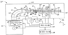
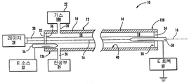
본 발명의 실시 예들은 가령 도 1a(종래 기술)에 도시된 주입 시스템 등의 이온 주입 시스템에 사용될 수 있는 질량(mass) 분해 애퍼쳐에 관한 것이다. 또 다른 실시 예들은 가령 폐쇄 플라스마 채널(closed plasma channel, CPC) 초전도체, 또는 도 1b(종래 기술)에 도시된 PC 등과 같은 보손 에너지 전달 시스템을 통해 충전된 및/또는 충전되지 않은 입자들의 유동을 여과하는 것에 관한 것이다.Embodiments of the present invention are directed to a mass dissociation aperture that can be used in an ion implantation system such as, for example, an implantation system as shown in FIG. 1A (prior art). Still other embodiments are directed to the flow of charged and / or uncharged particles through a bellows energy transfer system, such as a closed plasma channel (CPC) superconductor, or PC shown in FIG. 1B Lt; / RTI >
이온 주입은 집적회로들의 크기를 소형화하고 반도체 기판(예: 실리콘 칩)의 컴퓨팅 역량을 늘리기 위해 반도체 산업에서 선호되는 방법이다. 종래의 이온 주입 장치들은 기본적인 공통점들을 가지고 있다. 대상 가공물(work piece, 335)(예: 실리콘 칩)는 주입할 준비된 시점까지 처리가 된 경우 외부 소스에서 시스템 안으로 회전된다. 이온 소스(ion source, 302)는 생산 시스템의 타단부에 위치한다(이온화의 공급원료는 n 유형 접합들에 대해서는 안티몬, 비소, 인, 또는 p 유형 접합들에 대해서는 붕소, 갈륨, 인듐 등이 사용될 수 있다). 일반적으로, 양 이온이 사용되지만, 음 이온도 사용될 수 있다. 빔 조립 및 이온 주입 과정 중에는 이온 빔 안의 이온들이 잔여 가스들과 충돌하지 않도록 시스템의 대부분 또는 전체가 진공처리된다. 전시스템 전력(301, 340, 339)이 필요한 곳에 공급되고, 제어 시스템(338) 및/또는 운영자가 전체 과정을 감독한다. 이온 소스 공급원료는 p 유형 또는 n 유형 접합들을 바탕으로 선택된다. 이 이온 소스는 다양한 방법에 의해 이온화되고, 전극(305, 336)에 의해 이온화실(ionization chamber, 303)에 있는 개구를 통해 추출되는데, 여기서 전극(305, 336)은 유사 충전 이온들의 공간 전하 폭발(space charge blow-up) 성향을 경감시키기 위해 일반적으로 비교적 높은 에너지에서 방사된 이온 빔에 동력을 제공하도록 치우져 있다. 방사된 이온들은 질량 분석기(mass analyzer, 310)를 갖는 빔 가이드(beam guide, 317)로 진입하는 비교적 밀도 높은(고 전류)의 빔을 형성하는데, 이 질량 분석기(310)는 본래의 비행 경로로부터 약 90도의 각도로, 실질적인 포락선(envelope) 내에서 이온 빔을 구부리는 쌍극자 및/또는 사극자 자기장 및/또는 EM 자기장들로 이루어진다. 이온 빔 내의 이온 종(species)은 다른 전하 대 질량 비율을 갖고 있다. 웨이퍼 상의 균일한 집적 회로들은 주입된 이온들에 대한 전하 대 질량 비율로 설정된 파라미터들 안에 포함된다. 방사된 이온 빔(309)에서 부정확한 전하 대 질량 비율 종들은 질량 분석기(310)와 질량 분해 애퍼쳐(mass resolution aperture, 314)에 의한 추출 후 제거된다. 질량이 다르면 이온 종들에 대한 탄력도 달라지며, 질량 분석기(310)를 통해 궤도(trajectories)들을 분리할 것이다. 시스템 내 자기장들은 전하 대 질량의 비율이 원하는 비율보다 높은 이온 종들이 빔 가이드(311)의 하나의 벽을 치고, 전하 대 질량의 비율이 원하는 비율보다 낮은 종들은 빔 가이드(311)의 다른 쪽을 쳐서, 둘 다 지속되는 이온 빔으로부터 제거되도록 제어된다.Ion implantation is the preferred method in the semiconductor industry to miniaturize the size of integrated circuits and to increase the computing capacity of semiconductor substrates (e.g., silicon chips). Conventional ion implanters have basic commonalities. A work piece 335 (e.g., a silicon chip) is rotated into the system from an external source when it is processed until ready for implantation. The
다음으로, 종래의 대부분의 이온 주입 시스템들에서는, 이온 빔이 질량 분해 애퍼쳐(314)에 다다른다. 질량 분석기(310)에 의해 선택된 빔 전류는 대부분 원하는 이온 종들을 포함하나, 일부는 여전히 원하는 질량 대 전하 비율에 근접은 하나 같지는 않은 종들을 포함한다. 질량 분해 애퍼쳐(314)는 질량 분석기(126)로부터 나타나는 이온 빔 포락선보다는 작은 개구를 구비하며, 설정된 애퍼쳐 개구 바깥의 이온 종들, 질량 분해 애퍼쳐(314)의 측면을 치고 거기에 적층되는 이온 종들을 분해(제거)할 것이다.Next, in most conventional ion implantation systems, the ion beam reaches the mass resolving
제품 웨이퍼(또는 그 외 주입된 표면)의 실험 가능한 품질은 주입의 일관성에 달려 있다. 주입 전 및/또는 실제 주입 시, 빔은 일반적으로 애퍼쳐(314)의 하류로부터 주사(322)되고 프로파일(331)될 것이다. 제어 시스템(338)은 빔 진단 시스템(333)에 전달된 빔 프로파일 정보를 해석하여, 특정 주입을 위한 전하 대 질량 비율의 최상의 디자인 파라미터들 이내의 최대 전류를 허용하도록 애퍼쳐를 최적의 개구로 조정할 수 있다. 본 발명은 제어 시스템(338)과 콘트롤러들에게, 부정확한 이온들을 점점 더 많이 배제함으로써 질량 분해 애퍼쳐(314) 지점에서 빔을 최적화할 수 있는 높은 유연성과 함께 실시간 조정 역량을 제공한다.The testable quality of the product wafer (or other implanted surface) depends on the consistency of the implant. Before injection and / or during actual injection, the beam will generally be scanned 322 and
질량 분해 애퍼쳐(314)의 하류에는, 이온 빔의 초점을 맞추고, 구부리고, 굴절시키고, 모으고, 분기하고, 주사하고, 평행하게 하고 및/또는 오염 물질을 제거하는데 사용할 수 있는 많은 그 외 과정들 및 광학 효과들이 있다. 도 1은 종래 이온 주입 장치의 일 예를 도시하고 있다. 질량 분해 애퍼쳐(314)는 이온 빔 포락선(309)에서 질량 분석기(310)를 지나자마자 있다. 다른 이온 주입 시스템들은 소유 용도에 따라 달라진다. 상술한 바와 같이, 질량 분해 애퍼쳐 등과 같은 기본적인 구성 요소들은 거의 대부분의 시스템에서 흔하게 사용된다. Downstream of the mass resolving
2005년 미국의 전기 에너지 수요는 746,470 메가와트였다. 대부분의 에너지는 석탄(49.7%), 원자력 에너지(19.3%), 그리고 천연 가스(18.7%)로부터 생산되었다. 불행히도, 발생 지점에서부터 소매 지점까지의 에너지 운송은 여전히 매우 비효율적이다. 2005년의 5-8%의 에너지 손실은 거의 200억 달러의 손실로 환산될 수 있다. 생산된 에너지의 거의 대부분은 고압 전선을 통과한 후, 낮은 전압으로 변환되어 도시, 기업, 주거지 등으로 전달된다.In 2005, electrical energy demand in the United States was 746,470 megawatts. Most of the energy was produced from coal (49.7%), nuclear energy (19.3%) and natural gas (18.7%). Unfortunately, energy transport from the point of origin to the retail point is still very inefficient. Energy losses of 5-8% in 2005 can be converted to losses of nearly $ 20 billion. Almost all of the energy produced is converted to low voltage after passing through the high-voltage cable, and then transferred to cities, businesses, and residential areas.
모든 고압 전선들은 비교적 저렴한 가격, 및 (금속에 유리한) 17.2 × 10⁻⁵Ωm의 전기 저향력 때문에 절연 구리 배선을 사용한다. 구리로 이루어진 케이블이 700,000 볼트 이상의 전기를 운송할 수 있지만, 배선을 설치하는데 따르는 기계상의 제약과 전기적인 제약들 때문에 심각한 문제점을 내포하고 있다. 가령, 구리 케이블로 전기를 송전하는 방식은 케이블을 통과하는 전기의 저항으로 인해 발생 되는 열의 형태로 엄청난 양의 에너지가 손실되는 등 매우 비효율적이다. 게다가, 이렇게 해서 발생된 열은 전선을 변형시키거나 손상시킬 수 있는데, 전선이 너무 긴 경우는 특히 더하다. 케이블과 케이블을 매다는 타워 등은 미적으로 보기 좋지 않기 때문에 이러한 타워를 설치할 땅을 사용할 수 있는 권리를 얻는데 따르는 비용 또한 많이 드는 문제점이 있다.All high-voltage wires use insulated copper wiring at relatively low cost, and electrical resistance of 17.2 × 10 -5 Ωm (advantageous for metals). Although a cable of copper can carry more than 700,000 volts of electricity, it poses serious problems due to mechanical constraints and electrical constraints associated with wiring. For example, the transmission of electricity through a copper cable is very inefficient, with a huge amount of energy lost in the form of heat generated by the resistance of the electricity passing through the cable. In addition, this heat can deform or damage the wire, especially if the wire is too long. Because cables and cable towers are not aesthetically pleasing, the cost of obtaining the right to use these towers is also high.
지하 케이블은 매다는 방식의 전력 케이블에 비해 송전 거리가 길고, 전기 부하가 높고, 재산권 획득에 드는 비용이 적고 미관을 해치는 문제도 없다. 매몰식 구리 전선은 또한 최소 무게만을 지지하고 매다는 방식의 전선에 비해 전기의 유전 손실이 적은 더 개선된 유전 코팅을 갖고 있다. 그러나, 저항으로 인해 손실되는 효율은 여전히 큰 문제이다. 극저온 케이블은 지하 송전 케이블로 사용할 수 있는 두 번째 옵션인데, 저온을 유지하기 위한 액체 질소 기지가 요구되는 등 다른 비용 또한 발생한다. 초전도체 전선은 전기 저항으로 인한 손실이 없기 때문에 매력적인 해결 방안이나, 단일 결정 물질을 사용해 유용한 길이의 전선을 만드는 일은 불가능하지는 않더라도 실현이 어렵다. Underground cables have a longer transmission distance, higher electrical loads, lower cost of acquiring property rights, and less aesthetic appeal compared to hanging power cables. The buried copper wire also has a more improved dielectric coating that supports only minimal weight and has less dielectric loss than electrical wires of the hanging type. However, the efficiency lost due to resistance is still a big problem. Cryogenic cables are a second option that can be used as underground transmission cables. Other costs are also incurred, such as requiring a liquid nitrogen base to maintain low temperatures. Superconductor wires are an attractive solution because there is no loss due to electrical resistance, but it is difficult, if not impossible, to make wires of useful length using single crystalline materials.
에너지를 장거리에 걸쳐 운송하기 위한 좀 더 효율적인 수단의 필요성은 오랜 숙원임에 틀림 없다. 당업계의 이러한 필요를 충족하기 위해 자기장 및/또는 전자기장의 영향에 있는 좁고 막힌 형태의 플라스마를 통해 전력을 운송하기 위한 방법 및 장치가 제공된다. The need for more efficient means of transporting energy over long distances must be a long-cherished desire. Methods and apparatus are provided for transporting power through a narrow and clogged plasma in the influence of magnetic and / or electromagnetic fields to meet this need in the art.
양 단부에 전극이 형성되고 불활성 가스로 채운 유리관을 통해 전기를 전달할 수 있다는 것은 알려진 사실이다. 이러한 가스 튜브는, 외부 전기장을 가했을 때의 네온 튜브와 유사하다. 높은 전압의 교류 전기장 영향하에 있는 튜브에서는 가스 또는 일부 가스가 이온화되어 플라스마가 생성된다. 전자들은 모 가스 분자들에서 분리되고, 전기 전도성은 전기장이 가해지기 전의 가스보다 증가된다. 이러한 전자들은 구리와 같은 금속에서의 자유 전자들과 유사하게 행동한다. It is a known fact that electrodes can be formed at both ends and electricity can be delivered through a glass tube filled with an inert gas. Such a gas tube is similar to a neon tube when an external electric field is applied. In a tube under the influence of a high voltage alternating electric field, the gas or some gas is ionized to produce plasma. The electrons are separated from the parent gas molecules and the electrical conductivity is increased over the gas before the electric field is applied. These electrons act like free electrons in metals such as copper.
심지어 입자들의 1% 정도만 이온화되는 부분적으로 이온화된 가스들도 플라스마의 성질(자기장 및 높은 전기 전도성에 대한 반응)을 가질 수 있다. "플라스마 밀도(plasma density)"라는 용어는 보통 "전자 밀도(electron density)", 즉 단위 용적당 자유 전자들의 개수를 의미한다. 플라스마의 이온화의 정도는 전자들을 잃은(또는 얻은) 원자의 비율이며, 주로 온도에 의해 제어된다. 종종 플라스마는 거의 완전히 이온화되면 "고온 상태"인 것으로 간주되고, 가스 분자들의 적은 부분(가령 1%)만 이온화되면 "저온 상태"인 것으로 간주된다. 이러한 관점에서 볼때, "기술적 플라스마(technological plasma)"들은 보통 저온 상태이다. 그러나, "저온 상태"의 플라스마에서도 전자 온도는 여전히 섭씨 수천도이다.Even partially ionized gases, which are only ionized about 1% of the particles, can also have the properties of the plasma (the response to magnetic fields and high electrical conductivity). The term "plasma density" usually means "electron density ", i.e. the number of free electrons per unit volume. The degree of ionization of a plasma is the ratio of atoms that have lost (or obtained) electrons, and are primarily controlled by temperature. Often, the plasma is considered to be "hot" when it is almost completely ionized, and it is considered "cold" if only a small fraction (eg, 1%) of the gas molecules is ionized. From this viewpoint, "technological plasma" However, even in "low temperature" plasmas, the electron temperature is still thousands of degrees Celsius.
플라스마의 전기 전도성은 그 밀도와 관련 있다. 더 구체적으로는, 부분적으로 이온화된 플라스마에서, 전기 전도성은 전자 밀도에 비례하고 중성 가스 밀도에 반비례한다. 달리 말해, 하전 입자들의 재조합을 통해 존재하는, 이온화되지 않은 임의의 가스 매체는 계속해서 절연체 역할을 함으로써, 그것을 통과하는 전기의 운송에 저항력을 발생시킨다. 본 발명은 자기장에 대한 플라스마의 반응성 (그리고 상자성 가스 매체의 반응성)을 이용하여 에너지 운송 시의 저항력을 실질적으로 또는 전부 제거한다. 그 방법에 대해서는 아래에서 더 자세히 설명할 것이다. 이에 따라, 송전 효율은 실질적으로 거리와는 무관하나 1) 이온화 2) 진공의 품질 3) 자기장 성층화의 함수와 상관이 있게 된다. 이온화는 UV 광포화에 의해 유지되는 최적 광전 이온화일 것이고; 진공의 품질은 높거나 매우 높을 것이고, 이때의 결정 인자는 현존하는 이온화되지 않은 분자들의 MFP (평균 자유 경로)일 것이고; 자기장 성층화는 참여하지 않는 분자들과 입자들을 챔버 안에서 일부 영역에 분리하는 정적 자기장(static magnetic field)의 효과로 인한 것이 될 것이다. The electrical conductivity of a plasma is related to its density. More specifically, in a partially ionized plasma, the electrical conductivity is proportional to the electron density and inversely proportional to the neutral gas density. In other words, any non-ionized gaseous medium present through recombination of charged particles continues to act as an insulator, thereby creating resistance to the transport of electricity through it. The present invention utilizes the reactivity of the plasma to the magnetic field (and the reactivity of the paramagnetic gas medium) to substantially or completely eliminate the resistive force during energy transfer. The method will be described in more detail below. Accordingly, the transmission efficiency is substantially independent of the distance, but it is correlated with the function of 1) ionization 2) quality of vacuum 3) magnetic field stratification. Ionization will be optimal photo ionization maintained by UV light saturation; The quality of the vacuum will be high or very high, where the crystal factor will be the MFP (mean free path) of the existing non-ionized molecules; Magnetic field stratification will be due to the effect of the static magnetic field separating non-participating molecules and particles into some regions within the chamber.
본 발명의 실시 예들은 이온 주입 시스템에 사용될 수 있는 질량 분해 애퍼쳐에 관한 것으로, 여기서 이온 주입 시스템은 도 1a에 도시된 종래의 이온 주입 시스템, 또는 이온 빔 조립체에서 주입에 바람직하지 않은 전하 대 질량 비율 (및/또는 질량 대 전하 비율)을 바탕으로 이온 종들을 선택적으로 배체하는 장치들이 될 수 있다. 구체적인 일 실시 예는 도 1a에 도시된 이온 빔 조립체(308) 과정에 사용될 수 있는 MRA에 관한 것이다. 이온 주입 시스템들은 반도체 산업에서 가령 계산 회로(computing circuitry)를 생성하는데 사용된다. 이러한 시스템에서 가장 단순하나 가장 중요한 구성 요소 중 하나는 질량 분해 애퍼쳐(314)이다. 질량 분해 애퍼쳐(314)는 이온 추출부(ion extraction, 307)와 질량 분석 빔 가이드(mass analyzing beam guide, 310)의 하류에 위치한다. 질량 분해 애퍼쳐(314)는 원하는 전하 대 질량 비율에는 근접하나 특정 주입의 파라미터들 범위 안에 있지 않은 이온 종들을 분해한다. 원하는 이온 종들은 애퍼쳐 개구를 통과하고 원하지 않는 종들은 이온 빔을 마주보는 애퍼쳐 표면들을 침으로써 제거될 것이다. 원하지 않은 이온 종들은 애퍼쳐 같은 높이로(flush) 치고, 이온 빔 안으로 부분적으로 스퍼터(sputter)되어, 잔류물이 쌓이도록 한다. 이러한 잔류물 더미는 헐거워져서 이온 빔에 오염 물질이 들러붙게 하고 결국 대상 가공물(335)까지 도달할 수 있다. 집적 회로의 소형화를 위한 부단한 노력 덕분에, 더 높은 빔 전류를 사용하는 방법, 더 낮은 에너지에서 주입하는 방법, 더 큰 질량의 집단 분자들을 사용하는 방법, (빔 가이드 내 질량 분산의 범위가 작은) 게르마늄과 같은 대체 이온 소스를 사용하는 방법, 다중 이온 소스를 사용하는 방법, 및 그 외 이온 배제 과정 개선에 바람직한 방법들이 발전해왔다. Embodiments of the present invention are directed to a mass resolving aperture that can be used in an ion implantation system in which the ion implantation system can be used in a conventional ion implantation system, Can be devices that selectively distribute ion species based on ratio (and / or mass to charge ratio). One specific embodiment relates to an MRA that may be used in the
본 발명의 실시 예들은 또한 도 1b에 도시된 PC 등의 보손 에너지 전송 시스템(boson energy transmission system) 또는 폐쇄 플라스마 채널(closed plasma channel, CPC) 초전도체를 통해 충전된 입자들의 유동을 여과하는 것에 관한 것이다. 특정 실시 예들은, (질량-대-전하 비율 등의) 전하 및/또는 질량에 따라, (길쭉한 형상의 이온화 챔버 안에서, 이온화된 또는 부분적으로 이온화된 매체의 구성 요소들 등의 충전된 입자들의 국부적으로 분리된 유동을 여과하기 위한 방법 및 장치에 관한 것이다. 여기서, 이온화 챔버는 충전된 입자들의 전송을 위해 낮은 저항 또는 무-저항의 전도 경로를 제공한다. 본 발명에 따른 장치의 실시 예들은 넓은 적용 범위를 가지며, 저-에너지 입자 가속 장치(low energy particle accelerator)로도 설명할 수 있다.Embodiments of the present invention also relate to filtering the flow of charged particles through a boson energy transmission system or a closed plasma channel (CPC) superconductor, such as the PC shown in FIG. 1B . Certain embodiments may include, but are not limited to, localized (e.g., ionic or partially ionized) charged particles, such as components of an ionized or partially ionized medium, in an elongated ionization chamber, depending on the charge and / The ionization chamber provides a low resistance or no-resistance conduction path for the transfer of charged particles. Embodiments of the apparatus according to the present invention provide a wide It can also be described as a low energy particle accelerator.
본 발명의 실시 예들은 질량 분해 애퍼쳐에 관한 것으로, 더 구체적으로는, 분할되고, 조정 가능하고, 및/또는 애퍼쳐를 타격할 유입되는 이온 종들에게 곡선 표면을 제공하는 질량 분해 애퍼쳐에 관한 것이다. 조정 가능한 질량 분해 애퍼쳐에서는, 콘트롤러 및/또는 제어 시스템들이 더욱더 다양한 기능을 수행할 수 있다. 주입 사이클 이전에, 도중에, 및/또는 이후에 질량 분해 애퍼쳐를 조정할 수 있는 특성은 장점을 제공한다. 곡선 표면을 포함하는 실시 예들은 곡선 표면의 뒤에, 그리고 이온 빔으로부터 떨어진 곳에 잔류물이 증착되도록 함으로써, 대상 가공물(335)에 닿는 이온 빔 부분이 이온 아래에 그러한 잔류물이 들러붙도록 할 가능성을 줄여준다. 배제된 이온 종들은 곡선 표면상의 질량 분해 애퍼쳐를 칠 수 있고, 이는 부정확한 이온 종들의 스퍼터링(sputtering)을 완화시킨다.Embodiments of the present invention relate to a mass resolving aperture, and more particularly to a mass resolving aperture that provides a curved surface for ionized species to be segmented, tunable, and / will be. In an adjustable mass resolving aperture, the controller and / or control systems can perform more various functions. The ability to adjust the mass decomposition aperture before, during, and / or after the injection cycle provides advantages. Embodiments involving a curved surface allow for the deposition of residue behind the curved surface and away from the ion beam so that the portion of the ion beam that touches the
분할된 애퍼쳐의 실시 예들은 임의의 개수의 세그먼트들을 포함할 수 있다. 간단하게 설명하기 위해, 세그먼트들은 기능에 따라 설명할 것이다. 일 실시 예에 따르면, 애퍼쳐 몸체의 영역들 또는 세그먼트들은 서로 다른 전하 및/또는 자기 극성을 가질 수 있는데, 이는 이온들의 선택을 개선하기 위해 근처로 이동하는 이온들의 이동에 영향을 줄 수 있다. 또 다른 실시 예들에 따르면, 애퍼쳐의 각각의 측면은 다른 측면과 독립적으로 또는 협력하여 이동 또는 슬라이딩할 수 있도록 다른 측면들에 대해 이동 가능하다. 이러한 방식으로, 애퍼쳐 개구에 대한 제어는 수동으로, 또는 수동으로 제어하는 작동기들을 통해, 또는 운영 시스템을 통해 이루어질 수 있다. 이러한 조정은 실시간으로 이루어질 수 있으며, 충전된 입자들의 빔의 단면 및/또는 충전된 입자들의 빔의 축에 대해 원하는 위치에 원하는 크기로 애퍼쳐 개구를 형성할 수 있다. 실시간으로 조정함으로써 이온 빔은 주입 도중에도 조정할 수 있으며, MRA의 하류에서 획득한 측정치의 피드백을 바탕으로 조정하는 옵션도 가능하다. 여기서, 원하는 크기란, 이온 소스에서 기인한 빔 포락선을 바탕으로, 또는 원하는 질량 대 전하 비율 및/또는 분해도 등을 바탕으로, 작동 전에 기설정되거나 달리 결정된 빔 프로파일 피드백을 바탕으로 한 것일 수 있다.Embodiments of the divided apertures may include any number of segments. For the sake of simplicity, the segments will be described by function. According to one embodiment, regions or segments of the aperture body may have different charge and / or magnetic polarity, which may affect the movement of nearby ions to improve the selection of ions. According to yet other embodiments, each side of the aperture is movable relative to the other side so that it can move or slide independently or cooperatively with the other side. In this way, control over the aperture opening can be done manually, or through actuators that are manually controlled, or through an operating system. Such an adjustment can be made in real time and can form aperture apertures of a desired size at a desired location with respect to the cross-section of the beam of charged particles and / or the axis of the beam of charged particles. By adjusting in real time, the ion beam can be adjusted during injection and an option to adjust based on the feedback of the measurements acquired downstream of the MRA. Here, the desired size may be based on the beam envelope originating from the ion source, or based on predefined or otherwise determined beam profile feedback prior to operation based on the desired mass to charge ratio and / or resolution.
원하는 애퍼쳐의 크기에는 형태, 높이, 및 너비가 포함될 수 있다. 또한, 하나 이상의 애퍼쳐들의 정면이 분할되고 (즉, 전하 및/또는 자기 극성 또는 그 외 자기 속성을 보유), 자기적으로 고립되고, 및/또는 절연됨으로써, 역학적 간섭과 함께 하나 이상의 기능을 수행할 수 있다. 일 예로, 유입되는 이온 빔을 마주보는 애퍼쳐 표면은 (즉, 빔 경로와 평행한 구성 요소를 포함하고 이온 빔의 이동 방향과 반대인) (i) 그러한 표면이 패러데이 플래그(Faraday flag) 또는 빔 프로파일러의 기능을 수행하도록 분할되고; 및/또는 그러한 표면이 빈 필터(Wien filter)의 기능을 수행하도록 자기화될 수 있다. 일 예로, 이온 빔이 애퍼쳐에서 빠져나옴에 따라 이온 빔을 마주보는 애퍼쳐 표면은 가속화/감속화, 초점/초점이탈, 선택적 영향에 편향되거나, 및/또는 ZFE-한정 요소이거나 및/또는 특정 세청 과정 시 사용될 수 있다. 특정 실시 예들에서, 질량 분해 애퍼쳐 개구 전체는 다가오는 이온 빔에 대해서, X 축상에서 옆으로 이동하거나, Y 축상에서 상하로 이동하거나, Z 축상에서 전후로 이동할 수 있다. (도 1b 참조)The size of the desired aperture may include shape, height, and width. In addition, the front of one or more of the apertures may be segmented (i.e., having charge and / or magnetic polarity or other magnetic properties), magnetically isolated, and / or insulated to perform one or more functions with mechanical interference can do. In one example, an aperture surface facing the incoming ion beam (i. E., Including components parallel to the beam path and opposite to the direction of movement of the ion beam) (i) such surface has a Faraday flag or beam & Divided to perform the functions of the profiler; And / or such surface may be magnetized to perform the function of a Wien filter. In one example, the aperture surface facing the ion beam as the ion beam exits the aperture may be accelerated / decelerated, defocused / defocused, deflected to selective effects, and / or ZFE-confined and / It can be used in the custody process. In certain embodiments, the mass-resolving aperture openings may move sideways on the X-axis, up and down on the Y-axis, or back and forth on the Z-axis, relative to the approaching ion beam. (See FIG. 1B)
본 명세서에 기재된 바와 같이, 본 발명의 실시 예들은 질량 분해 애퍼쳐의 충전된 입자들의 빔과 접촉하거나 그 움직임에 영향을 주는 부분들을 위한 곡선 표면을 포함한다. 일 예로, 개구를 형성하고 및/또는 유입되는 이온 빔을 마주보는 애퍼쳐의 내부 표면은 엣지를 형성할 수 있다. 표면은, 엣지에는 유입되는 빔과 가장 가까운 선도 부분(leading portion)이 형성되고, 표면은 엣지의 선도 부분으로부터 빔의 외부로 갈수록 볼록하도록 (즉, 빔으로부터 멀어지면서 곡선을 이루도록) 곡선으로 이루어질 수 있다. 또 다른 실시 예들에서는, 선도 부분에 인접한 위치에 개구로부터 멀어지는 방향으로 오목한 표면이 형성될 수 있다. 선도 부분에서 멀어질수록 볼록해지도록 표면이 형성되면, 제거된 이온들이 평평한 표면을 같은 높이로 치지 않고, 곡선 표면을 치게 되기 때문에, 제거된 이온 종들이 MRA를 치는 스퍼터링(sputtering)을 완화할 수 있다. 또 다른 실시 예들에 따르면, 오목한 부분에 인접한 위치에 오목한 세그먼트가 형성될 수 있다. 그러면, 애퍼쳐상의 잔류물은 방사상으로 엣지 바깥 부분, 엣지의 축의 방향으로 상류에 위치하게 되는데, 즉 곡선 표면 뒤에 위치하게 되어 이온 빔에 달라붙는 것이 덜하다. 분리 시점에 엣지의 방사상으로 바깥 방향으로 애퍼쳐 표면을 치는 이온 종들은 곡선 표면에 의해 이온 빔의 바깥으로 편향될 수 있다. 애퍼쳐의 분할 및 애퍼쳐의 곡선은 동시에 또는 개별적으로 사용하여, 특히, 더 높은 빔 전류, 대상 가공물에서 더 낮은 에너지, 분자 집단 이온, 원거리 또는 다중 이온 소스 및 그 외 적극적인 계수 크기 조정 전략(scaling strategies) 등에 있어서 이온 주입 과정의 균일성과 생산성을 향상시킬 수 있다.As described herein, embodiments of the present invention include curved surfaces for portions that contact or influence the movement of the charged particles of the mass decomposition aperture. In one example, the inner surface of the aperture forming an aperture and / or facing the incoming ion beam can form an edge. The surface is formed with a leading portion closest to the beam entering the edge, and the surface can be curved (i.e., curved away from the beam) from the leading portion of the edge toward the outside of the beam have. In other embodiments, a concave surface may be formed in a direction away from the opening at a location adjacent the leading portion. As the surface is formed to be convex as it moves away from the leading portion, the removed ion species can hit the curved surface without striking the flat surface at the same height, so that the removed ion species can mitigate the sputtering of the MRA have. According to still other embodiments, a concave segment may be formed at a position adjacent to the concave portion. Then, the residue on the aperture is radially positioned upstream of the edge, in the direction of the axis of the edge, i.e., behind the curved surface, and is less likely to stick to the ion beam. Ion species that strike the aperture surface radially outwardly of the edge at the point of separation can be deflected out of the ion beam by a curved surface. The splitting and aperture curves of the apertures can be used simultaneously or individually to provide a higher beam current, lower energy in the target workpiece, molecular mass ions, a remote or multi-ion source, and other active scaling strategies and the like, the uniformity and productivity of the ion implantation process can be improved.
본 발명의 실시 예들은 폐쇄 플라스마 채널(closed plasma channel, "CPC") 초전도체, 또는 보손 에너지 전달 장치로 특징지워지는 시스템에 관한 것이다. 특정 실시 예들은 미국 특허 번호 8,368,033에 기재된 시스템 및 방법에 대한 변형 및 개선 사항에 대한 것이고, 전문이 참조로서 포함된다. 제1 바람직한 실시 예에 따르면, 상기 장치는 이온화 공간(본 발명의 일부 실시 예에서는 "플라스마 분리 공간"이라고도 함)을 구비한 이온화 용기(본 발명의 일부 실시 예에서는 "플라스마 분리 용기"라고도 함)을 포함하는 이온화 챔버(본 발명의 일부 실시 예에서는 "플라스마 분리 챔버"라고도 함), 및 이온, 전자, 및 비온화되지 않은 가스나 증기(이하 "플라스마 구성 요소들")로 구성된 플라스마로 진공 상태에서 플라스마 전구 가스 또는 가스를 이온화하기 위한 이온화 공간과 연동되는 광이온화 수단으로 이루어진다. 바람직하게는, 플라스마 전구 가스 또는 증기는 상자성을 띤다. 이온화는 가장 전도성 높은 전달 매체를 생성하기 위해 적합한 파장의 빛 소스의 광전 효과에 의해 구현 및 유지된다. Embodiments of the present invention are directed to a system characterized by a closed plasma channel ("CPC") superconductor, or a boson energy transfer device. Specific embodiments are modifications and improvements to the systems and methods described in U.S. Patent No. 8,368,033, the full text of which is incorporated herein by reference. According to a first preferred embodiment, the apparatus comprises an ionization vessel (also referred to as a "plasma separation vessel" in some embodiments of the present invention) having an ionization space (also referred to in some embodiments as "plasma separation space" (In some embodiments of the invention, also referred to as a " plasma separation chamber "), and a plasma comprising ions, electrons, and non-ionized gases or vapors (hereinafter" plasma components ") And a photoionization means interlocked with an ionization space for ionizing the plasma precursor gas or gas. Preferably, the plasma precursor gas or vapor is paramagnetic. Ionization is implemented and maintained by the photoelectric effect of a light source of the appropriate wavelength to produce the most conductive transmission medium.
제2 바람직한 실시 예에 따르면, 플라스마는 상술한 용기 자체내에 형성되지 않고 용기에 충전될 수 있다. 두 가지 경우 모두, 플라스마 구성 요소들을 용기의 중앙 길이방향 축에 평행하게 배치된 "영역들" 또는 "채널들" 안으로 실질적으로 분리하기 위해, 전송 공간 안에 축의 방향으로 균질한 정적 자기장을 생성하도록 자기장 생성 수단이 사용된다. 각각의 채널은 이온화 공간의 전체 길이를 따라 형성된다. 적어도 하나의 채널은 주로 자유-전자들로 이루어지도록 형성되는데, 이는 본 발명의 일 적용 예에서는, 그것을 통과하는 전기 전송에 대한 최소한의 저항을 갖는 경로를 제공한다. 다른 실시 예들에 따르면, 진동 자기장(전자기장 또는 "교란장")이 도관을 통한 충전된 입자들의 이동을 촉진하도록 전송 공간 안에 도입된다. 본 방법 및 장치의 다양한 추가적인 실시 예들은 교류, 또는 원통형 벽을 통과하는 다중극 EM 장(field)들 또는 적어도 하나의 지역화된 채널들을 통과하는 직류나 충전된 입자들을 위한 하이브리드 시스템을 포함하는 것으로 설명되었고, 이 과정은 다른 적용 예들 뿐 만 아니라 초전도체, 낮은 에너지 입자 가속 장치로 기능할 수 있다. 모든 실시 예들에서, 상술한 광이온화 수단이 플라스마를 유지하는데 (즉, 플라스마의 구성 요소들의 재결합을 방지하도록) 사용될 수 있다. 전송 공간을 통한 충전된 입자들의 전송 효율을 향상시키기 위한 방법 또한 설명되었다.According to a second preferred embodiment, the plasma can be filled in the vessel without being formed in the vessel itself as described above. In both cases, a magnetic field is created to create a homogeneous static magnetic field in the direction of the axis in the transfer space, in order to substantially separate the plasma components into "regions" or "channels" arranged parallel to the central longitudinal axis of the vessel Generating means is used. Each channel is formed along the entire length of the ionization space. At least one channel is formed primarily of free-electrons, which in one application of the invention provides a path with minimal resistance to electrical transmission through it. According to other embodiments, an oscillating magnetic field (electromagnetic field or "disturbance field") is introduced into the transmission space to facilitate movement of charged particles through the conduit. Various additional embodiments of the present methods and apparatus are described as including a hybrid system for direct current or charged particles passing through alternating current, or multipolar EM fields, or at least one localized channel through a cylindrical wall And this process can function as a superconductor, low energy particle accelerator as well as other applications. In all embodiments, the photoionization means described above can be used to maintain the plasma (i.e., to prevent recombination of the components of the plasma). A method for improving the transmission efficiency of charged particles through the transmission space has also been described.
자기성 또는 상자성을 갖는 다양한 구성과 밀도의 플라스마 구성 요소들은 전송 공간 안에서 이산된 자기극성과 반응하여, 전도 내지 절연 속성들에 의해 주문된 실질적으로 별도의 영역들 또는 또는 "점진적 영역들(gradations)"로 되는데, 각 구성 요소의 질량/전하 비율은 정적 자기장에 대해 더 크거나 더 작은 반응을 나타내는데 유용하다. 따라서 전도 영역 또는 점진적 영역의 위치는 다른 자기장 생성 수단을 사용해 조정할 수 있고, 여기에는 전도층이 주로 자기장의 중앙에 있는 실시 예와 주로 도관의 내부 벽 표면을 따라 배향된 실시 예가 포함된다. Plasma components of various constructions and densities with magnetic or paramagnetic properties react with discrete magnetic polarities in the transmission space to produce substantially separate regions or "gradual regions " ordered by conduction or isolation properties, &Quot;, where the mass / charge ratio of each component is useful for indicating a larger or smaller response to the static magnetic field. Thus, the position of the conduction region or the progressive region can be adjusted using other magnetic field generating means, including embodiments in which the conduction layer is primarily at the center of the magnetic field and are oriented primarily along the inner wall surface of the conduit.
전도 채널이 자기장의 중앙에 있는 실시 예들에서는, 전자기(EM)장, 즉 교류 또는 임의의 다중극장이 적용될 수 있다. 이러한 경우, EM장은 도관의 벽을 따라 형성되는 "교란장"이라 할 수 있고, 제1 자기장은 전도 채널을 중앙을 향해 집중시키는 "계층장(stratum field)"이라 할 수 있다. 이 두 번째 EM장이 최초 장의 계층을 교란시킬 수 있지만, 그 영향력은 충전된 입자들(DC 전류)을 유인 및 물리치거나 도관의 회수 단부(retrieval end)에 위치한 수신 수단으로의 유동을 가속하거나 증진시키는 방식으로 풀-푸쉬(pull-push) 하도록 개선될 것이다. 벽 전하 또한 수신 단부에 위치한 동일한 또는 추가적인 수신 수단에 의해 회수될 것이다. 또 다른 실시 예들에서도, 다른 목적을 위해 다른 조합에서 같은 원리를 사용할 수 있다.In embodiments where the conduction channel is at the center of the magnetic field, an electromagnetic (EM) field, e. G. AC or any multiple theater, may be applied. In this case, the EM field may be referred to as a " disturbance field " formed along the wall of the conduit, and the first magnetic field may be referred to as a " stratum field " Although this second EM field can disturb the layer of the first field, its effect is to accelerate or enhance the flow of the charged particles (DC current) to the receiving means located at the retrieval end, To be pull-pushed in such a way that the The wall charge will also be recovered by the same or an additional receiving means located at the receiving end. In other embodiments, the same principle can be used in different combinations for different purposes.
본 발명의 또 다른 측면은 도관 안에서 광이온화를 사용하는 것이다. 플라스마 매체는 최대 전도성 수준으로 유지되며, 광 수치와 파장의 품질은 플라스마가 가장 풍부한 상태에서 자연에서 본 상태이며, 보손 에너지 매개체를 포함한다. 본 발명의 장치와 방법에서, 플라스마 밀도는 운동 효과의 저항을 줄이기 위해, 자기유체역학(MHD) 분야의 다른 적용 예들과 비교했을 때 비교적 엉성하다. 도관에서 지속되는 플라스마의 상태는 융합 플라스마 보다는 공간 플라스마에 더 가깝다. 본 발명의 장치 및 방법들은 지구 대기 밖, 즉 "우주"에 많은 플라스마의 자연 상태를 모방하여 설계되었는데, 이는 광활한 거리 사이에서는 효율적인 에너지 전송 매체인 것으로 증명되었다. 이것을 달성하기 위해, CPC에서는 높은 진공 품질 내지 매우 높은 진공 품질이 요구된다. 결정 인자는 챔버 안의 이질적인 분자들의 "평균 자유 경로(MFP)"이다. 이 MFP는 방해하는 분자들을 물리치는 정적 자기장의 도움을 받아 전하의 경로를 방해하는 충돌로 인한 전하를 극복할 수 있을 정도로 길어야 한다. Another aspect of the invention is to use photoionization within the conduit. The plasma medium is maintained at the maximum conductivity level, and the optical value and the quality of the wavelength are natural in the state of the plasma being the most abundant and include the boson energy medium. In the apparatus and method of the present invention, the plasma density is relatively poor compared to other applications in the field of magnetohydrodynamics (MHD) to reduce the resistance of motion effects. The state of the plasma continuing in the conduit is closer to the spatial plasma than to the fused plasma. The apparatus and methods of the present invention have been designed to mimic the natural state of many plasmas outside the Earth's atmosphere, the "space, " which has proven to be an efficient energy transfer medium between vast distances. To achieve this, high vacuum quality to very high vacuum quality is required in CPC. The determinant is the "mean free path" (MFP) of the heterogeneous molecules in the chamber. The MFP should be long enough to overcome the charge due to collisions that interfere with the path of the charge with the aid of a static magnetic field that hinders interfering molecules.
본 발명의 특정 실시 예들은 CPC, 또는 용기 내의 전구체를 이온화하고 그 결과로 발생된 이온들로 힘을 전달하여 이온 빔을 형성하도록 구성되고, 이온 빔 안의 특정 이온들의 움직임에 영향을 주기 위한(가령 이온들의 방향을 변경하거나, 편향시키거나 및/또는 이온 빔에서 이온들을 제거하는 등) 핀(fin), 곡선 표면, 또는 분할된 돌출 부분들 등의 필터를 용기 내부 표면에 포함하는 시스템에 관한 것이다.Certain embodiments of the present invention provide a method for ionizing a CPC or precursor in a vessel and transferring the force to the resulting ions to form an ion beam and for affecting the movement of specific ions in the ion beam, A curved surface, or divided protruding portions, etc., in the interior of the vessel, such as by changing the orientation of ions, deflecting ions, and / or removing ions from the ion beam) .
이어질 본 발명의 상세한 설명의 이해를 돕기 위해, 그리고 당업계에 대한 본 발명의 공헌이 더잘 인정받을 수 있도록, 본 발명의 더 중요한 구성 요소들 및 특징들의 개요를 다소 넓게 설명했다. 물론 본 발명에 대한 추가적인 특징들에 대한 설명도 이어질 것이고, 이 특징들은 첨부된 청구항들의 대상이 될 것이다. 이러한 관점에서, 본 발명의 적어도 일 실시 예를 상세히 설명하기 전에, 본 발명이 상세할 설명에서 명시한 또는 도면에서 도시한 세부 구성 및 구성 요소들의 배열에 한정되지 않음을 이해해야 할 것이다. 본 발명은 다른 실시 예로서도 구현될 수 있으며 다양한 방식으로 실시 및 수행될 수 있다. 또한, 본 명세서에서 사용한 문구나 용어는 설명의 목적으로 사용되었을 뿐 한정의 목적이 아님을 이해해야 할 것이다. 이와 같이, 당업자는 본 명세서가 바탕으로 하고 있는 개념이 본 발명의 몇몇 목적들을 달성하기 위한 다른 구조, 방법 및 시스템을 설계하기 위한 기초로 사용될 수 있음을 이해할 것이다. 따라서, 본 발명의 정신과 범위를 벗어나지 않는 한 상기 등가 구성들이 청구항에 포함되는 것으로 간주하는 것이 중요하다.In order that the following detailed description of the invention will be better understood and the contribution of the present invention to the art be more appreciated, we have outlined rather broadly the more important components and features of the invention. Of course, further features of the invention will now be described, which will be the subject of the appended claims. In view of the above, before describing in detail at least one embodiment of the present invention, it is to be understood that the invention is not limited to the precise configuration and arrangement of components set forth in the following description or illustrated in the drawings. The present invention may be implemented as other embodiments and may be implemented and carried out in various ways. It is also to be understood that the phrase or terminology used herein is for the purpose of description and not of limitation. As such, those skilled in the art will appreciate that the concepts on which this disclosure is based can be used as a basis for designing other structures, methods and systems for accomplishing several objects of the present invention. It is important, therefore, that the equivalents be regarded as including the claimed constituent parts in the appended claims unless they depart from the spirit and scope of the present invention.
본 발명은 이어질 상세한 설명을 참조로 할 때 더 잘 이해될 것이며 상술한 것 외의 목적들도 명백해질 것이다. 본 발명의 상세한 설명은 다음과 같은 첨부된 도면을 참조로 한다.BRIEF DESCRIPTION OF THE DRAWINGS The invention will be better understood with reference to the following detailed description, and other objects will become apparent. The detailed description of the invention refers to the following appended drawings.
도 1a는 미국 특허 번호 8,637,838 B2에서 재현한 것으로, 본 발명의 실시 예들을 위한 하부 시스템들을 제공할 수 있는 이온 주입 시스템의 일 예로 사용되었으며, 본 발명의 실시 예들에 따라 변경도 가능하다.
도 1b는 미국 특허 번호 8,368,033에서 재현한 것으로, 본 발명의 실시 예들을 위한 하부 시스템을 제공할 수 있는 폐쇄 플라스마 채널 장치의 일 예로 사용되었으며, 본 발명의 실시 예들에 따라 변경도 가능하다.
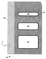
도 2는 미국 특허 번호 7,399,980 B2에서 재현한 것으로, 본 발명의 실시 예들을 위한 하부 시스템들을 제공할 수 있는 질량 분해 애퍼쳐의 종래 기술이며, 본 발명의 실시 예들에 따라 변경도 가능하다.
도 3a는 본 발명의 일 실시 예에 따른, 이온 빔 포락선에 비해 어느 높이나 너비로도 애퍼쳐가 점차적으로 이동될 수 있도록 하는 슬라이드 형 측면들을 구비한 질량 분해 애퍼쳐를 도시한 도면이다.
도 3b는 완전히 개방된 도 3a의 질량 분해 애퍼쳐를 도시한 도면이다.
도 3c는 완전히 폐쇄된 도 3a의 질량 분해 애퍼쳐를 도시한 도면이다.
도 4a는 나사 돌리개(screw drive)와 두 개의 공압식 돌리개(pneumatic drive)를 포함하는, 본 발명의 구체적인 일 실시 예를 도시한 도면이다.
도 4b는 나사 돌리개와 기어를 포함하는, 본 발명의 구체적인 일 실시 예를 도시한 도면이다.
도 5a는 본 발명의 일 실시 예에 따른 핀(fin)의 단면도이다.
도 5b는 질량 분해 애퍼쳐의 안측 엣지로 사용될 수 있는 곡선 엣지를 도시한 도면이다.
도 6은 슬라이딩 면들(sliding sides)과 함께 곡선형 안측 엣지를 포함하는 MRA의 일 실시 예를 도시한 도면이다.
도 7은 도 5a 및/또는 도 5b의 곡선형 엣지를 포함하는 일 실시 예의 길이방향 단면도이다.
도 8a는 본 발명의 일 실시 예에 따른, 곡선형 표면, 또는 "핀(fin)"의 단면도이다.
도 8b는 본 발명의 일 실시 예에 따른, 곡선형 표면, 또는 "핀(fin)"의 단면도이다.
도 8c는 본 발명의 일 실시 예에 따른, 곡선형 표면, 또는 "핀(fin)"의 단면도이다.Figure 1a is reproduced in U.S. Patent No. 8,637,838 B2, which is used as an example of an ion implantation system capable of providing subsystems for embodiments of the present invention, and may be modified in accordance with embodiments of the present invention.
1B is an illustration of a closed plasma channel device that is reproduced in U.S. Patent No. 8,368,033, which can provide a subsystem for embodiments of the present invention, and may be modified in accordance with embodiments of the present invention.
2 is a prior art description of a mass decomposition aperture which is reproduced in U.S. Patent No. 7,399,980 B2 and which can provide subsystems for embodiments of the present invention, and may be modified in accordance with embodiments of the present invention.
FIG. 3A is a view illustrating a mass decomposition aperture having slide-type side surfaces, in which the aperture can be gradually moved at any height or width as compared with the ion beam envelope, according to an embodiment of the present invention.
Fig. 3b is a view showing the mass decomposition aperture of Fig. 3a, which is fully open.
Figure 3c is a view showing the mass decomposition aperture of Figure 3a fully closed.
4A is a diagram illustrating one specific embodiment of the present invention, including a screw drive and two pneumatic drives.
FIG. 4B is a view showing a specific embodiment of the present invention including a screwdriver and a gear. FIG.
5A is a cross-sectional view of a fin according to one embodiment of the present invention.
5B is a view showing a curved edge that can be used as the inner edge of the mass resolving aperture.
Figure 6 is an illustration of an embodiment of an MRA that includes a curved inner edge with sliding sides.
Figure 7 is a longitudinal cross-sectional view of one embodiment including curved edges of Figures 5a and / or 5b.
8A is a cross-sectional view of a curved surface, or "fin ", in accordance with an embodiment of the present invention.
8B is a cross-sectional view of a curved surface, or "fin ", in accordance with an embodiment of the present invention.
8C is a cross-sectional view of a curved surface, or "fin ", in accordance with an embodiment of the present invention.
시작하기에 앞서, 본 발명의 도면들에 표시된 참조 부호는 동일한 요소들, 부분들 또는 표면들을 나타낼 목적으로 사용되었다는 것을 이해해야 할 것이다. 이러한 요소들, 부분들 또는 표면들은 본 상세한 설명이 필수 부분인 본 명세서 전반에서 더 상세히 묘사 또는 설명할 것이다. 달리 표시하지 않은 한, 본 발명의 도면들은 (즉, 교차 해칭(cross-hatching), 부분들의 배열, 비율, 정도 등 포함) 본 명세서와 함께 읽을 용도로 사용되었으며, 본 발명의 서면 설명 전체의 한 부분으로 간주되어야 한다. 구성 요소들은 축척 또는 비율에 따라 도시된 것이 아니다. 이어지는 상세한 설명에 사용된 바와 같이, "수평" 및 "수직"등의 용어는 단순히 평평한 지면에 대한 대상의 배향을 지칭하는 것이며, "좌측", "우측", "상측", 그리고 "바닥", "상" 및 "하" 등의 용어들, 그리고 그들의 형용사형과 부사형들(가령, "우측으로", "좌측으로" 등)은 단순히 그들의 연장 축, 또는 회전 축 중 적합한 것에 대한 표면의 배향을 지칭하는 것이다. Before starting, it is to be understood that reference signs shown in the drawings of the present invention are used for the purpose of indicating the same elements, portions or surfaces. These elements, portions, or surfaces will be described or illustrated in greater detail throughout this specification where this description is an integral part. Unless otherwise indicated, the drawings of the present invention (including cross-hatching, arrangement of parts, ratio, degree, etc.) have been used for purposes of reading along with this disclosure, Section. The components are not drawn to scale or ratio. As used in the following detailed description, the terms "horizontal" and "vertical" and the like refer to the orientation of the object relative to a flat surface only, and the terms "left," " right, "& Terms such as " top "and" bottom ", and their adjective forms and adverbs (e.g., "to the right "," to the left ", etc.) merely indicate the orientation of the surface .
종래 기술로서 미국 특허 번호 8,637,838의 도면 1을 재현한 도 1a는 종래의 이온 주입 시스템을 도시하고 있다. 종래의 이온 주입 시스템들은 일반적으로 질량 분해 애퍼쳐(314)를 구비한다. 도 1a에서는 MRA을 포함하는 시스템을 도시하고 있다. 본 발명의 실시 예들은 도 1a의 시스템, 도 1a에 도시된 하부 시스템들 및 상기 시스템 및 하부 시스템들과 관련하여 그 전문이 참조로서 사용된 미국 특허 번호 8,637,838에 기재된 실시 예들, 그리고 미국 특허 번호 8,637,838의 도 1에 도시된 하부 시스템들 및 미국 특허 번호 8,637,838에 도시된 변형 예들에 관한 것으로, 이온 경로의 길이 방향으로 형성된 하나 이상의 이온 경로 위치들에 형성된 본 명세서에서 설명하는 MRA의 실시 예들 중 하나에 따른 하나 이상의 MRA를 포함한다. 본 발명은 질량 분해 애퍼쳐를 구비한 다른 시스템들과 함께 작동할 것이다.Figure 1a of the prior art, reproduced in Figure 1 of U.S. Patent No. 8,637,838, shows a conventional ion implantation system. Conventional ion implantation systems generally have a
본 발명의 일 실시 예에 있어서, 도 1a를 참조로, 대상 가공물(335), 가령 실리콘 웨이퍼는 상기 시스템의 단부 기지(end station, 336)에서 이온 빔에 의해 주입된다. 이온 빔(309)은 단자(307)에서 생성된다. 이온 빔은 빔 라인 조립체(beam line assembly, 308) 내의 경로를 따라 단부 기지(336)까지 유도된다.In one embodiment of the present invention, with reference to FIG. 1A, a
이 시스템은 다른 입자들과의 이온 빔 충돌을 완화하기 위해 펌프(미도시)에 의해 진공처리 될 수 있다. 이온 소스(302)는 도펀트 물질(미도시)을 생성 챔버(304) 안에서 이온화한 가스일 수 있다. 이온화 방법은 도시되지 있지 않으나, 가령, 열음극(cathode), RF, 극초단파, 전자 빔 주사, 또는 그 외에도 도펀트 가스 분자들과 충돌하기에 충분한 자유 전자들을 여기하고 이온들을 생성할 메커니즘일 수 있다. 이온들은 슬릿(slit, 303)을 통해 이동하고 이온 추출 조립체(ion extraction assembly, 305)에 의해 추출된다.The system can be vacuumed by a pump (not shown) to mitigate ion beam collisions with other particles. The
추출 조립체(305)는 비교적 높은 에너지에서 이온들을 추출하도록 마련되었다. 일반적으로, 시스템들은 비교적 높은 에너지에서 시스템 전반에 빔을 전송하기 때문에, 입자들은 빔 폭발로 이어질 수 있는 반발력을 극복할 충분한 탄력을 갖고 있다. 그러면, 대상 가공물(335)과의 충격 전에, 감속단(327)들이 있는데, 여기에는 이온들을 감속함으로써, 작은 접합들이나 초박막 접합(ultra-shallow junctions, USJ)를 위해 웨이퍼와 얕은 충격을 갖도록 하는 전극 조립체들이나 그 외 장치들이 포함될 수 있다. 주지할 사실은, 감속단(327)이 이온 빔에 평행한 전극판(328, 330)들로 도시되어 있긴 하나, 다른 감속단들도 빔 경로에 수직이고 빔이 통과하는 애퍼쳐들을 포함하는 전극들을 활용할 수 있다. The
이온 빔(309)은 추출된 후 단자(307)에서 빔 라인 조립체(308)로 이동한다. 도 1b에 도시된 실시 예에서는, 질량 분석기(310)가 약 90도로 형성되어 있고, 빔(309)을 구부리는 자기장을 제공한다. 자석들은 이 도면에는 도시되어 있지 않다. 빔 라인 조립체의 나머지 부분은 빔 가이드(317), 질량 분석기(310), 스캔 시스템(320, 319, 122), 전기 요소(339), 그리고 평행화 부분(329)을 포함한다.The
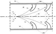
종래 기술인 미국 특허 번호 8,368,033의 도 1의 재현인 도 1b는 폐쇄 플라스마 채널 초전도체 또는 보손 에너지 전달 장치를 도시하고 있다. 본 발명의 실시 예들은 하나 이상의 핀(fin) 또는 이온화 용기(12)의 벽(14)의 내부 표면으로부터 돌출되는 곡선 표면을 갖는 돌출 부분들을 포함함으로써, 그러한 핀 또는 핀들이 이온 빔의 이동에 영향을 주거나 및/또는 이온 빔에서 이온을 제거하도록 한다.FIG. 1B, which is a representation of FIG. 1 of the prior art U.S. Patent No. 8,368,033, shows a closed plasma channel superconductor or boson energy transfer device. Embodiments of the present invention include protruding portions having a curved surface that protrudes from the inner surface of the
종래 기술인 미국 특허 번호 7,399,980의 도 4의 재현인 도 2는 종래의 질량 분해 애퍼쳐의 일 예를 도시하고 있다. 본 MRA의 실시 예들은 이온 빔들이 통과하는 애퍼쳐에 근접하게 배치된 핀을 포함하도록 도 1의 MRA를 변형한 것들일 수 있다. 이러한 핀은 유입되는 이온 빔에 가장 가까운 선도 부분을 포함할 수 있고, 특정 실시 예들에서는, 선도 부분에서부터 곡선을 이루어 선도 부분에 인접한 위치에 볼록한 표면을 형성함으로써 그러한 볼록 부분을 막는 이온들을 이온 빔 바깥으로 편향시키는 표면을 포함할 수 있다. 이러한 핀은 전하 및/또는 자기적 성질을 갖는 두 개 이상의 세그먼트(예: 각 세그먼트의 용적은 핀과 같음)들을 포함할 수 있다. 이러한 핀들은 이온 빔의 너비를 형성하는 측면들의 엣지 전체 또는 일부를 따라 배치될 수 있고 및/또는 이온 빔의 높이를 형성하는 상측 및 하측 엣지들의 전체 또는 일부를 따라 배치될 수 있다. 이러한 판의 실시 예들은 하나, 두 개, 세 개 또는 그 이상의 개구를 포함할 수 있고, 이때 각각의 개구는 높이와 너비 등의 원하는 크기로 형성될 수 있다. 분해 애퍼쳐 조립체(resolving aperture assembly, 400)의 변형 실시 예들은 세 개의 분해 애퍼쳐(406, 408, 410) 등과 같은 하나 이상의 개구(1, 2, 3, 4,…n)를 구비한 분해판(resolving plate, 404)을 지지하는 조립체 팔(assembly arm, 402)을 포함할 수 있다. 실시 예들에 따르면, 선택된 애퍼쳐가 선택된 빔 포락선 및/또는 선택된 질량 분해도와 대응되도록 조립체는 가령 작동기들을 통해 이동될 수 있다. 조립체는 또한 질량 분석기의 상류(미도시) 방향으로의 조정 가능한 각도 범위에 대응되는 다양한 빔 경로들을 수용하도록 이동할 수 있다. 애퍼쳐 개구들의 제1, 제2, 및 제3 위치들이 작동 시 서로 나란히 있기 때문에, 빔의 일부 물질 또는 부분들은 선택되지 않은 애퍼쳐들 중 하나를 통과할 수 있다.Figure 2, which is a representation of Figure 4 of the prior art U.S. Patent No. 7,399,980, shows an example of a conventional mass resolving aperture. Embodiments of the present MRA may be those that have modified the MRAs of FIG. 1 to include pins disposed proximate to the aperture through which the ion beams pass. Such a pin may include a leading portion closest to the incoming ion beam, and in certain embodiments, forming a convex surface at a position adjacent to the leading portion of the curved line from the leading portion, 0.0 > a < / RTI > These fins may include two or more segments having charge and / or magnetic properties (e.g., the volume of each segment is the same as a pin). These fins may be disposed along all or a portion of the edges of the sides forming the width of the ion beam and / or along all or part of the upper and lower edges forming the height of the ion beam. Embodiments of such plates may include one, two, three or more openings, wherein each opening may be formed to a desired size, such as height and width. Modified embodiments of the resolving
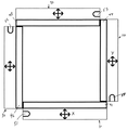
도 3a는 질량 분해 애퍼쳐 조립체(30)의 일 실시 예를 도시한 도면이다. 도 3a에서의 애퍼쳐 개구 위치는 도 2에 (페이지의 평면에) 도시된 애퍼쳐 개구(410)와 대체로 대응된다. 조립체는 측면들(31, 32, 33, 및 34)을 포함하고, 이 측면들은 X 및 Y 방향으로 슬라이딩함으로써 다양한 개구 크기와 위치를 형성한다. 이 측면들은 너비가 동일하고, 길이는 측면의 엣지에서부터 시작해서, 측면들이 도 3c에 도시된 위치로 일단 이동되면 도 3a에서 측면이 가리고 있던 개구 부분을 가릴 정도로까지 연장 형성되지 않는다. 그리고 이는 측면들의 이동 범위가 강조되도록 도시의 편의를 위해 이렇게 표현했다. 측면들의 이동을 제어하는데는 기어, 트랙, 연결 부분, 작동기, 모터 등 다양한 메커니즘을 사용할 수 있다. 측면들(31, 32, 33, 및 34)은 각각 엣지들(41, 42, 43, 및 44) 안쪽의 애퍼쳐를 따라 슬라이딩한다. 애퍼쳐 측면들(31~34)은 애퍼쳐 개구가 측면들(31~34)의 작동 범위 내에서 어떤 개구 크기로도 조정될 수 있도록 하는 개구를 갖는 뒷판에 대해 슬라이딩할 수 있다.FIG. 3A is a diagram illustrating one embodiment of a mass
도 3b에서는 작동 범위내 최대 개구 애퍼쳐로 이동된 측면들(31~34)을 도시하고 있고, 뒷판의 개구의 크기와 위치에 대응될 수 있다. 이러한 뒷판은 측면들과 측면들을 이동시키기 위한 구조간의 상호 연결 시 마운트(mount)로 사용될 수 있다. 이 개구는 측면들을 이 최대 개구까지 개방함으로써 빔 경로에서 MRA를 "제거"할 수 있도록 질량 분석기(310)에서 나타나는 빔 포락선을 초과할 수 있다. 주입 전에 최대 개구를 사용하는 것은 질량 분해 애퍼쳐 하류에서의 빔 진단에 유용할 수 있다. 이 최대 개구의 설정은 또한 이온 빔이나 질량 분해판의 시스템 하류를 통해 그 외 가스들이 확산되는 특정 클리닝 기술에도 사용될 수 있다.3B shows the side faces 31 to 34 moved to the maximum opening aperture within the operating range and can correspond to the size and position of the opening of the back plate. This back plate can be used as a mount when interconnecting the structures to move the sides and sides. This opening may exceed the beam envelope appearing in the
도 3c에서는 애퍼쳐가 완전히 폐쇄되도록 측면들(31~34)이 이동된 것을 도시하고 있다. 이러한 설정은 이온 빔을 막고 자기장이 질량 분석기(310)에서 여전히 작동 가능한 빔 덤프(dump)를 위해 사용될 수 있다. 이러한 설정은 질량 분해 애퍼쳐를 비롯해 시스템 상류를 통해 이온 빔이나 그 외 가스들이 확산하는 특정 클리닝 기술들에도 사용될 수 있다. 도 3c에서 볼 수 있는 바와 같이, X 및 Y 방향, 그리고 선택적으로 Z 방향으로 이동 가능한 네 개의 측면들을 갖는 실시 예의 경우, 네 개 측면들의 다양한 위치들은 폐쇄 위치를 형성할 수 있다. 일 실시 예에 따르면, 완전히 폐쇄된 위치는 이온-빔을 완전히 막는다.3C shows that the side faces 31 to 34 are moved so that the aperture is completely closed. This setting can be used for a beam dump that blocks the ion beam and the magnetic field is still operable in the
측면들의 다른 위치들도 선택될 수 있다. 애퍼쳐 개구의 어떤 위치라도, 즉, 개구의 중심 위치든, 또는 개구의 엣지들을 위한 위치든, 작동 범위내에서 선택될 수 있다. 또한, 뒷판을 갖는 조립체(30), 뒷판이 없는 조립체(30), 및/또는 조립체, 뒷판 및 그 외 구조는 작동 범위내에서 옆으로 (X 축), 상하 (Y 축), 전후 (Z 축) 방향으로 선택적으로 이동됨으로써 이온 빔(309)에 대한 개구를 조정할 수 있다.Other positions of the sides can also be selected. Can be selected within the operating range, at any position of the aperture opening, i.e., the center position of the aperture, or the position for the edges of the aperture. Further, the
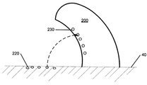
질량 분해 애퍼쳐 조립체(30)는 전원 공급부(340, 339)에 작동 가능하게 결합될 수 있다. 제어 시스템(337)은 이온 소스(302), 질량 분석기(313), 질량 분해 애퍼쳐 조립체(30), 스캔 요소(322), 평행화 요소(329), 및 빔 프로파일링 시스템(331) 및/또는 그 외 장치의 작동 가능한 측면을 제어, 조정 및/또는 이들과 통신하는데 사용될 수 있다. 빔 진단 시스템(338)은 주입 과정 이전, 도중 및/또는 이후에 빔 특성들을 관리하기 위해 시스템내에서 반복적인 변경이 가능하도록 제어 시스템(337)에 연결될 수 있다. 이를 통해, 가령 제어 시스템(337)은 대상 가공물(335)을 시스템 단부 기지(336) 안으로 회전시키기 전에 질량 분해 애퍼쳐 측면들(31~34)을 완전히 개방된 애퍼쳐 도 3b에 설정할 수 있고, 빔 진단이 완료되고 파라미터들이 설정될 수 있다. 빔 파라미터들이 일단 설정되면, 제어 시스템(337)은 가령 주입 과정을 시작, 변형 및/또는 종료하기 위해 원하는 파라미터들에 부합하는 어떠한 원하는 애퍼쳐로도 측면들(31~34)을 이동시킬 수 있다. 그러면, 주입 과정 중에, 가령 제어 시스템(337)은 빔 진단(338) 시스템으로부터의 데이터를 사용해 질량 분해 애퍼쳐 조립체(30) 또는 측면들(31~34)을 점차적으로 이동시켜서 빔 특성들을 관리 및/또는 최적화할 수 있다. 주입 과정 후 또는 새로운 대상 가공물(미도시)이 단부 기지(336)로 회전되는 동안에는, 가령 제어 시스템(337)은 클리닝 과정이나 그 외 목적을 위해 완전히 폐쇄된 위치, 도 3c로 측면들(31~34)을 이동시킬 수 있다. 제어 시스템(337)은 질량 분석기 안의 자기장들이 작동하는 동안 빔 덤프를 위해 측면들(31~34)을 완전히 폐쇄된 위치, 도 C로 이동시킬 수 있을 것이다. 질량 분해 애퍼쳐 조립체(30)의 기능들은 실시간으로 반복적으로 수행될 수 있다. 본 발명의 MRA의 실시 예들은 각각의 개구의 또는 개구들의 하부 세트를 위해 곡선형 안쪽 엣지들, 가령 핀들을 하나 이상의 측면 또는 측면의 섹션에 포함함으로써 종래의 질량 분해 애퍼쳐를 변형할 수 있는데, 그 중 한 예가 도 2에 도시되어 있다. 본 발명의 일 실시 예에서는, 본 명세서에 도시되고 묘사된 곡선 표면들이 애퍼쳐 안쪽 엣지들에 사용될 수 있다. 본 명세서에 기재된 곡선 표면들은 가령 도 2에 도시된 바와 같이 종래 기술을 비롯한 어떠한 형태의 종래 질량 분해 애퍼쳐에서도 사용 가능하다. 이온 빔(309)이 (도 2에 도시된 종래 시스템의) 질량 분해 애퍼쳐 조립체(314)에 도달할 때 까지도 공간 전하 폭발 가능성을 완화하기 위해 비교적 높은 에너지로 이동한다. 감속단(deceleration stages, 327)들은 애퍼쳐에서 하류에 있기 때문에, 배제된 이온 종(species)들은 비교적 높은 속도에서 질량 분해 애퍼쳐의 선도 단부를 침으로써 기존부터 존재하는 잔류물을 비롯해 오염 물질들을 이온 빔으로 스퍼터링(sputtering) 하는 성향을 보이고, 상기 오염 물질은 빔 안에 달라붙어서 대상 가공물(335)까지 도달할 수 있다. 이는 특히 높은 빔 전류, 더 무거운 질량의 클러스터 분자, 다중 이온 소스 및 질량 분산 범위가 좁은 이온 소스들에서 특히 분명히 나타난다. 곡선 표면들이 다른 표면들에 비해 갖는 이점은 배제 시점에 부딪치게 되는 표면을 더 적게 제공하고 배제된 이온 종들은 곡선 표면 플러시에 영향을 주지 않으며 이들이 편향되면 지속되는 이온 빔은 이미 하류로 이동했기 때문에 배제된 이온 종들로부터의 오염 물질이 대상 가공물에 달라붙어서 오염시킬 가능성은 줄어든다는 것이다. 배제된 이온 종들로부터의 잔류물은 주입 가동 시간 동안 질량 분해 애퍼쳐 상에 쌓일 수 있으나, 애퍼쳐 개구에서 멀리 떨어져 있고 질량 분해 애퍼쳐의 곡선 엣지 뒤에 있다. 본 명세서에서 묘사한 곡선 표면들은 배제된 이온 종들, 배제된 중립 충전 또는 음성 충전 입자들 또는 상류 시스템 부분으로부터의 오염 물질들이 마모되어 표면을 치는 시스템 내 다른 표면들에도 사용될 수 있다. 대상 가공물(335)의 상류 어딘가에서 여기에 기재된 방식으로 생산 라인에 재진입하는 것을 막는 것은 생산 품질 및 효율에 기여할 것이다.The mass
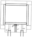
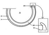
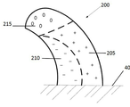
도 5b는 도 5a에 도시된 고리 형태 대신 단일 애퍼쳐 개구를 갖는 직사각형 질량 분해 애퍼쳐를 도시하고 있다. 새로운 표면(40) 내에 형성된 측벽(14)이 도 5a와 도 5b에 도시되어 있다. 비록 도 5a와 도 5b가 측벽(14)을 도시하고 있지만, 이 측벽은 도 2에 도시된 바와 같이 판이 되도록 두꺼워질 수 있고, 도 2에서는 또한 판에서 연장형성되는 핀을 나타낸다. 핀의 세부 사항(200)이 도 5a와 도 5b 둘다에 도시되어 있다. 본 발명의 일 실시 예에 따르면, 평평한 또는 플러시(flush) 애퍼쳐 대신, 그리고 앞에서 뒤로 각도가 90도 (Z 축에 평행)인 엣지 대신 본 명세서에 기재된 바와 같이 곡선 엣지를 포함하도록 종래 질량 분해 애퍼쳐가 변형되었다. 종래의 질량 분해 애퍼쳐를 본 명세서에 기재된 바와 같이 유입되는 이온 빔(309)을 마주보는 애퍼쳐의 안쪽 엣지에 곡선 표면을 갖도록 변형하면 빔에 달라붙어서 대상 가공물(335)을 오염시킬 수 있는 부정확한 이온 종들이 스퍼터링(sputtering) 되는 것과 잔류물 및 오염 물질이 곡선 뒤에 적층되는 것을 완화할 수 있다. 작동 시, 잔류물이 축적되는 것은 애퍼쳐 개구에서 하류로 통제됨으로써 잔류물이 헐거워져서 빔까지 도달하는 것을 막는다.Figure 5b shows a rectangular mass resolving aperture with a single aperture opening instead of the ring shape shown in Figure 5a. The
도 8a 및 도 8b는 MRA와 함께 포함될 수 있는 핀들의 실시 예들을 도시하고 있다. 비록 측벽(14)의 표면(40)이 도 5a와 도 5b에서는 (유입되는 빔을 마주보는) 정면을 지나도록 연장형성되고 (유입되는 빔을 등지는) 후면을 지나도록 연장형성되나, 측벽 표면(40)은 판으로서 기능하도록 두꺼워질 수 있고, 측벽 표면(40)은 정면으로부터 후면을 지나도록 연장형성되거나, 정면으로부터 후면까지 연장형성되거나, 그 외 정면 및 후면에 대한 임의의 원하는 방향으로 연장형성될 수 있다. 영역(205)은 양성, 음성 또는 중성 전하를 띌 수 있다. 영역(210)은 영역(215)과 마찬가지로 양성, 음성 또는 중성 전하를 띌 수 있다. 충전된 영역들은 부정확한 질량을 갖는 충전된 이온 종들을 배제하는데 사용될 수 있다. 실시 예들은 크기, 영역의 개수 및/또는 영역의 형태를 비롯해 다양한 방식으로 분할될 수 있다. 세그먼트들은 유리한 경우 임의의 개수로 형성될 수 있음은 쉽게 이해될 것이다. 설명의 편의를 위해, 이 실시 예에서는, 세 개의 세그먼트(205, 210 및 215)들이 도시되었다. 또한, 유리한 경우 곡선 표면들도 임의의 개수로 형성될 수 있음을 쉽게 이해할 것이다. 이러한 형태는 한정의 목적이 아닌 설명의 편의를 위해 사용되었다. 세그먼트들(205, 210, 및 215)은 바람직하게는 서로에 대해 절연되고 자기적으로도 서로 분리됨으로써 각각은 정전기적으로 유리한 및/또는 자기적으로 유리한 서로 다른 음성 또는 양성 전하/장(field)을 가지거나 전하를 전혀 갖지 않을 수 있다. 도 23B에 도시된 바와 같이, 가령 세그먼트(205)는 음성 전하/장을 띠고, 세그먼트(210)는 양성 전하를 띠고, 세그먼트(215)는 전하를 갖지 않는다. Figures 8A and 8B illustrate embodiments of pins that may be included with the MRA. Although the
이온 빔(309)에 있어서, 이온 빔(309)이 세그먼트(215)에 도달함에 따라, 세그먼트(215)는 전하를 갖지 않으며, 세그먼트(205)는 원하는 전하 대 질량 비율에 근접하지만 파라미터에 해당되지는 않는 양성 이온 종들을 유인할 수 있는 충분한 음성 전하/장을 띠며, 이러한 이온 종들은 세그먼트(205)의 방향으로 이동하고 거기에 머무르는 경향을 띠게 되는데, 유인력 있는 음성 전하/장 때문에 스퍼터링(sputtering)은 줄어든다. 같은 예에서, 세그먼트(215)의 표면, 즉 애퍼쳐의 배제 지점과 부딪치는 양성 이온 종들의 경우, 곡선 표면 때문에 이온 빔으로부터 편향된다. 계속해서 같은 예에서, 이온 빔이 이제 이 이점에서 세그먼트(309)를 지날 때, 세그먼트(210)는 양성 전하/장 또는 음성 전하/장을 전달하거나 전하를 전달하지 않을 능력을 가짐으로써 이온 빔(309)에 유리하게 영향을 미칠 수 있다. 질량 분해 애퍼쳐의 각각의 세그먼트는 독립적으로 활용될 수 있고 다양한 조합으로 활용될 수도 있음은 쉽게 이해될 것이다. 가령, 양성 이온 종들 대신 음성 이온 종들이 추출되면, 질량 분해 애퍼쳐의 세그먼트 전하들은 본 명세서에 기재된 바와 같이, 음성 이온 주입의 주입 파라미터들에 대응하도록 변경될 것이다. 또는, 가령 수소화 붕소 클러스터 이온들이나 게르마늄 이온 종들을 사용한 경우, 질량 분해 애퍼쳐는 본 명세서에 기재된 바와 같이, 제조에 유리한 조정 가능한 옵션들을 제어 시스템과 콘트롤러에 제공한다.In the
도면에 도시되어 있지 않지만, 개구 주변에 90도 엣지를 갖는 MRA는 전하/자기장 세그먼트들로 분할될 수 있다. 특정 실시 예에 따르면, 개구에 근접하나 개구를 통과해야 하는 이온들에는 영향을 주지 않을 정도로 개구에서 떨어진 애퍼쳐의 정면(face surface)의 세그먼트는, 배제되어야 하고 엣지와 부딪칠 가능성이 높고 빔으로 다시 편향될 수 있는 이온들을 유인하는 전기 전하를 띨 수 있다.Although not shown in the figure, an MRA having a 90 degree edge around the aperture can be divided into charge / magnetic field segments. According to a particular embodiment, a segment of the face surface of the aperture away from the aperture such that it does not affect the ions that are close to the aperture but must pass through the aperture must be excluded and is likely to hit the edge, An electric charge can be drawn which attracts ions that can be deflected again.
다양한 핀 형태가 다양한 실시 예들에 사용될 수 있다. 특정 실시 예에서는, 엣지에서 시작해서 이온 빔으로 굽어서 들어가는 곡선 표면을 갖는 핀이 사용될 수 있다.Various pin shapes may be used in various embodiments. In certain embodiments, a pin having a curved surface that begins at the edge and bends into the ion beam may be used.
비록 도 4a와 도 4b가 도면 하단에는 이동 가능한 측면을 도시하고 상단에는 함께 고정될 수 있는 세 개의 측면을 도시하고 있으나, 도 4a와 도 4b의 기재에 따른 실시 예들은 일 측면을 수직 방향 또는 수평 방향으로 이동시키는데 사용될 수 있다. 세 개 측면들은 함께 고정되어 하나의 유닛으로 이동할 수 있고, 또는, 네 개 측면들이 모두 연결된 토대(base)가 이동될 수도 있다. 네 번째 측면이 이온 빔의 높이나 너비를 조정하도록 이동된 경우, 하나의 유닛 및 개별 측면들을 이동하는 것은 이온 빔에 대한 개구의 중심을 조정하는데 유용할 수 있다. Although Figures 4a and 4b illustrate three side surfaces that are movable at the bottom and can be secured together at the top, the embodiments according to Figures 4a and 4b illustrate one side in a vertical or horizontal Lt; / RTI > direction. The three sides may be fixed together to move to one unit, or the base to which all four sides are connected may be moved. If the fourth side is moved to adjust the height or width of the ion beam, moving one unit and the individual sides may be useful for adjusting the center of the aperture for the ion beam.
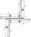
도 6은 질량 분해 조립체(30)의 독립적으로 이동 가능한 측면들의 용도를 도시한, 본 발명의 추가적인 실시 예의 도면이다. 여기서, 도 5a내지 도 5b 그리고 도 8a 내지 도 8c에서 앞서 설명한 핀 표면들은 슬라이딩 측면들(31~34)의 선도 엣지로서 도시되었고, 41~44은 각각 핀 엣지(61~64)로 대체되었다. 이 실시 예에서는, 도 3a 내지 도 3c에 도시된 조정 가능한 질량 분해판 조립체(30)의 선도 엣지들이 핀 엣지(61~64)들이다. 질량 분해 애퍼쳐(30)의 이동 범위는 작동 가능한 공간 내에서 X 축에서는 옆으로, Z 축에서는 안팎으로, 그리고 Y 축에서는 상하로 이동하는 범위를 갖는다. 또 다른 실시 예에서는, X 축과 Y 축 방향으로의 이동만 허용된다. X, Y, Z 축상의 질량 분해 애퍼쳐(30)의 이동은 빔 진단 센터(155)와 작동 가능한 통신을 하는 제어 시스템(337) 및/또는 콘트롤러에 의해 제어된다. 제어 시스템(337) 및/또는 콘트롤러와 작동 가능한 통신을 통해 빔 진단 시스템(338)으로부터 작동 가능한 데이터를 수신하는 슬라이딩 면(31~34)들과 핀 엣지(61~64)들은 도 3b의 완전히 개방된 상태에서 도 3c의 완전히 폐쇄된 상태로, 또는 완전히 개방된 상태와 완전히 폐쇄된 상태의 중간 상태로 실시간으로 점진적으로 이동할 수 있는 역량을 갖고 있다.Figure 6 is a view of a further embodiment of the present invention showing the use of independently movable sides of the
본 발명의 실시 예들은 영구 자석을 사용해 빈공간(cavity) 안에 균일한 자기장을 생성함으로써 질량에 따른 이온 분리를 위한 방법 및 장치를 활용할 수 있다. 이는 진공 상태에서 플라스마 전구체 가스나 증기를 광이온화하여 막힌 공간 안에 바람직하게는 저밀도의 플라스마를 생성함으로써 달성된다. 질량이 크거나 질량-대-전하 비율이 큰 이온들은 자기장의 영향을 받지 않고 더 가벼운 이온들, 또는 질량-대-전하 비율이 낮은 이온들과는 분리되는 성질을 갖기 때문에 질량 또는 질량-대-전하 비율에 따른 분리가 발생한다. Embodiments of the present invention can utilize methods and apparatus for mass-dependent ion separation by creating a uniform magnetic field in a cavity using permanent magnets. This is accomplished by photo ionizing the plasma precursor gas or vapor under vacuum to produce a preferably low density plasma in the clogged space. Since ions having a large mass or a large mass-to-charge ratio are not affected by a magnetic field and are separated from lighter ions, or ions having a low mass-to-charge ratio, mass or mass-to- Separation occurs.
먼저 도 1b은 폐쇄된 플라스마 채널 장치 (이하 더 간단히 "본 발명의 장치"라고도 함)의 개략적인 측단면도이며, 여기서 폐쇄된 플라스마 채널 장치는 참조 부호 10을 사용한다. 장치(10)의 제1 주요 구성 요소는 이온화 챔버(12)(이하 몇몇 실시 예에서는 "플라스마 분리 챔버"라고도 함)로, 이온화 공간(이하 몇몇 실시 예에서는 "플라스마 분리 공간"이라고도 함)을 포함하는 이온화 용기(이하 몇몇 실시 예에서는 "플라스마 분리 용기"라고도 함)를 포함한다. 바람직한 일 실시 예에 따르면, 이온화 챔버(12)는 제1 단부 부분(12A) 및 제2 단부 부분(12B)을 구비한 반유연성의 길쭉한 형태의 진공 도관으로 구성되고, 이 도관은 길이방향 축(16)을 포함하고 저장 용기(22)로부터 입구(20)를 통해 공급되는 플라스마 전구체 가스 또는 증기(100)를 담기 위한 전송 공간(18)을 형성하는 중공 원통형 벽(14)을 포함한다. "챔버"와 "도관"은 본 명세서에서는 달리 명시적으로 구분하지 않는 한 서로 대체가능하게 사용되었다. 진공 시스템(24)은 벽(14)을 통과하도록 배치된 출구(26)을 통해 전송 공간(18)에서 공기를 빼기 위해 도관(12)에 작동 가능하게 부착된다. 도관(12)은 복수의 별도의 부분들이 서로 결합되어 전송 공간(18)을 형성하도록 구성될 수도 있고, 일체형으로 구성될 수도 있다. 도관(12)과 전송 공간(14)의 단면은 원형, 타원형, 다각형, 또는 그 외 형태일 수 있으며, 실험을 통해 설정된 시스템의 에너지 전달 효율을 바탕으로 선택된다. 1B is a schematic side cross-sectional view of a closed plasma channel device (hereinafter more simply referred to as "the device of the present invention "), wherein the closed plasma channel device uses the
이온화 수단은 도관(12) 내부에서 플라스마 전구체 가스(100)를 이온화하기 위해 제공된다. 그러나, 플라스마 전구체 가스(100)의 이온화는 별도의 챔버에서 수행한 후 전송 공간(18)으로 옮길 수도 있음을 쉽게 이해할 것이다. 이러한 옵션에도 불구하고, 충전된 입자들의 재결합을 지속적으로 처리하기 위해, 도관(12) 내에서 이온화를 수행하는 것이 바람직하다. 가스나 증기 상태로 다시 재결합되는 것도 발생할 수 있는데 이는 바람직하지 않다. 플라스마 전구체 가스들은 이온 상태에서는 전도체가 되고 가스 상태에서는 절연체가 되는 보즈-아인슈타인 원칙(Bose Einstein principle)을 일반적으로 따른다. 자외선, X-선, 방사선, 단 쇠(glowing metals), 연소 가스, 그리고 전자 충돌에 의한 이온화 모두 가능하나 전자에 언급된 것이 바람직하다.The ionization means is provided for ionizing the plasma precursor gas 100 within the conduit 12. However, it will be readily understood that the ionization of the plasma precursor gas 100 may be carried out in a separate chamber and then transferred to the
적합한 파장의 레이저 빔은 먼 거리에서도 가스나 증기 매체를 관통 및 이온화할 수 있음은 알려진 사실이다. 이에 따라, 플라스마 전구체 가스(100)로 충전된 전송 공간(18)으로 이온화 빔(30)("레이저 빔")을 발광하기 위한 이온화 빔 발광 수단(28)이 제공된다. 본 발명에 사용된 "이온화 빔 발광 수단"이라는 용어는 현재 알려진 레이저와 레이저 다이오드뿐만 아니라 매체에서 이온화를 촉진할 수 있는 높은 입체 호도성(steradiancy)을 갖는 광 소스들을 포함한다. 레이저는 고도높게 증폭되고 하나 이상의 이산 주파수들의 일정한 전자기 방사에 의해 빔을 발생시키기 위한 에너지 수준 사이의 원자 또는 분자들의 자연 진동을 활용한다. 플라스마 전구체 가스(100)를 이온화하는데 사용되는 레이저 수단은 에너지, 펄스폭, 및 파장을 바탕으로 선택되어야 한다. 전송 공간(18)은 깨끗하고 건조하게 유지해야 하고, 플라스마 전구체 가스(100)의 완전한 이온화를 방해할 만한 어떠한 촉매제나 불순물이 없도록 닦아야 한다.It is a well-known fact that laser beams of suitable wavelength can penetrate and ionize gas or vapor media even at long distances. There is thus provided an ionizing beam emitting means 28 for emitting an ionizing beam 30 ("laser beam") into a
도관(12)의 제1 단부 부분(12A)의 개구부에는 개구부를 가로질러 구획 거울(parcel mirror, 32)이 장착되고, 반대 단부 부분(12B)의 개구부에는 개구부를 가로질러 고체 반사 거울(solid reflective mirror, 34)이 장착된다. 구획 거울(32)과 고체 거울(34)은 각각 전송 공간(18)을 마주보는 반사면(36, 38)을 갖는다. 구획 거울(32)은 이온화 빔 발광 수단(28)에 의해 생성된 이온화 빔(30)이 도관(12)의 전송 공간(18) 안으로 통과할 수 있도록 하나, 빛이 반대 방향으로는 통과하지 못하게 하며, 대신 반응 공간(18)으로 다시 반사시킨다. 전송 공간(18) 내에서의 이온화 빔(30)의 반사는 플라스마 전구체 가스(100)의 균일한 광이온화를 촉진한다.A
전송 공간(18) 전반에서 플라스마 전구체 가스(100)가 균일하게 광이온화되도록 하기 위해, 벽(14)의 내부면(40)은 UV 범위에서 빛, 특히 단파장의 빛을 반사하는데 있어 매우 효율적이어야 한다. 또는, 광공진기(optical cavity) 또는 광공명기(optical resonator) 기술이 사용될 수 있는데, 이러한 기술은 광파를 위해 사용되는 정상파 공진 공명기를 형성하는 거울들의 배열로 이루어진다. 광공진기들은 레이저의 주요 구성 요소로서, 이득 매체(gain medium)를 둘러싸고 레이저 빛의 피드백을 제공한다. 공진기에 갇힌 빛은 여러 번 반사되어 특정한 공명 주파수를 위한 정상파를 발생시킨다.The
플라스마 전구체 가스(100)가 일단 이온화되어 원하는 플라스마 밀도를 달성하면, 플라스마 구성 요소들은 전송 공간(18) 안에 적용된 자기장에 대한 반응으로 길이방향 축(16)에 평행으로 연장형성되는 지역화된 채널들로 실질적으로 분리된다. 각각의 채널은 주로 단일 플라스마 구성 요소(예: 전자, 이온 또는 중성 입자)로 이루어지며, 전송 공간(18)의 전체 길이를 따라, 더 구체적으로는, 먼저 제1 단부 부분(12A)에서 시작해서 제2 단부 부분(12B)까지 연장형성된다. 하나의 채널은 주로 자유-전자("전자 채널" 또는 "전자 경로")들로 이루어지고 에너지가 통과할 수 있도록 최소한의 저항을 갖는 경로를 제공한다. 몇몇 실시 예에 따른 자기장 생선 수단에 대해 아래에서 설명할 것이다. 일반적으로, 이온화 가스를 포함하는 전송 공간 전반에 먼저 균질한 축 자기장이 형성됨으로써 플라스마를 그 이온, 전자 및 중성 입자 구성 부분들로 분리하는데, 각각의 구성 요소는 길이방향 축(16)에 평행한 실질적으로 별도의 영역을 포함하고, 각각의 영역은 서로 다른 전도성 정도를 갖는다. 이 과정은 플라스마의 "계층화"라고 일컬을 수 있다.Once the plasma precursor gas 100 has been ionized to achieve the desired plasma density, the plasma components are transferred to the localized channels extending in parallel to the
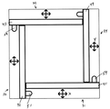
제1 실시 예에 따르면, 도관(12) 자체에 의해 전송 공간(18) 안에 자기장이 형성되는데, 도관(12)의 원통형 벽(14)은 자화(magnetization, 44)의 방향이 다양하고 자기 세그먼트(42)들의 어레이로 이루어지고 (즉, "할바흐 원통(Halbach cylinder)"), 이 자기 세그먼트(42)들은 도관(12)의 전송 공간(18)에만 한정되는 자속(magnetic flux)을 생성한다. 당업자라면 도관(12)의 외부 반경 대 내부 반경의 비율이 각각의 자화된 세그먼트(42)의 개수와 자화 방향과 마찬가지로 전송 공간(18) 내에 원하는 자속을 달성하는데 중요한 역할을 한다는 것을 이해할 것이다. 도 3을 참조로, 벡터장 화살표(46)로 표시된 바와 같이, K=2 종의 원통에 의해 생성된 자기장의 방향이 바닥에서 상단까지 (가로로 위로) 균일하다는 것을 알 수 있다. K-2 할바흐 배열은 균일한 자기장을 생성한다. 이 배열에 대한 변형이 도 4에 도시되어 있는데, 여기서 쐐기(48)로 형성된 복수의 영구 자석들이 원하는 중공 도관(12) 안으로 배치되어 있다. 아벨(Abel)과 젠슨(Jensen)이 제안한 이 배열은 또한 전송 공간(18) 안에 균일한 장을 제공한다. 각각의 쐐기(48)의 자화 방향은 아벨(Abele)이 제시한 일련의 규칙들을 사용해 계산되고, 벽(14)과 전송 공간(18)의 형태를 자유롭게 구현할 수 있도록 한다. 균일하지 않은 자기장을 사용하는 실시 예들도 구현 가능하다. 주지할 사실은, 벡터장 화살표(46)들이 증명하는 바와 같이, 자화(44)의 방향을 다양한 패턴으로 구현함으로써 전송 공간(18) 안의 자속은 더 복잡해진다는 점이다. 이에 따라, 이러한 배열들은 동일한 플라스마 구성 요소로 된 하나 이상의 채널을 사용하는 등 채널들이 더 복잡하게 배열된다. 이에 따라, 이러한 배열로는 단일 전송 공간(18) 안에 하나 이상의 전자 경로가 생성될 수 있다.A magnetic field is formed in the
"자기 맹글(magnetic mangle)"로 알려진 또 다른 디자인 상의 변형에 따르면, 자기장 생성 수단이 도관(12) 바깥에 형성되고, 일 실시 예는 복수의 균일하게 자화된 봉(uniformly magnetized rods, 50)으로 구성되는데, 이들은 그 길이방향 축(16)에 평행하게, 도관(12)의 외주면에 점진적으로 이격되어 배치된다. 이 봉들은 할바흐 원통의 장 생성 효과를 모방하기 위해 서로 다른 자화(44) 단면 방향을 갖는다. 관찰되는 바와 같이, 도시된 배열은 k=2 할바흐 원통과 밀접하게 연관된다. 서로에 대해 봉(50)들을 회전시키면 동역학적으로 다양한 장 및 다양한 쌍극성 구성들을 비롯해 많은 가능성을 제공한다. 도관(12) 외부에 자기장 생성 수단을 제공하는 실시 예들은 도관이 전도성 또는 비전도성 물질로 이루어질 수 있는 이점을 제공한다. 반경식 폴리머, 세라믹 및 유리 등이 고려될 수 있다.According to another design variant, known as a " magnetic mangle ", magnetic field generating means are formed outside of the conduit 12, and one embodiment may comprise a plurality of uniformly magnetized rods 50 Which are disposed in such a manner that they are gradually spaced apart from the outer circumferential surface of the conduit 12 in parallel to the
또 다른 실시 예에 따르면, 도관 외부의 전자기장 생성 수단은 전송 공간(18) 안에 원하는 길이방향 채널 안으로의 플라스마 구성 요소들의 분리를 위한 전자기장을 제공하도록 배열된 적어도 하나의 전자석으로 구성된다. 4중극 전자석이 도시되었으나 장거리 전력 전송에 적합한 길이의 도관에 적용하기에는 이상적이지 못하다.According to another embodiment, the electromagnetic field generating means external to the conduit is comprised of at least one electromagnet arranged to provide an electromagnetic field for the separation of the plasma components into the desired longitudinal channel in the
도 1b를 참조로, "지역화" 자기장이 전송 공간(18) 안에 일단 형성되고 플라스마 구성 요소들이 축 방향으로 정렬된 영역들로 분리되면, 전원(52)으로부터 전류 "I"가 인출되어 자기장 "B"에 수직인 도관(12)을 통과함으로써, 크기와 방향 두 가지를 모두 갖는 전자기력 "F"(로렌츠 힘)을 생성한다. 간단한 설명을 위해, 자기장 "B"는 상술한 자기장 생성 수단보다는 두 개의 영구 자석(54A, 54B) 사이에서 나타난다. 전자기력 "F"의 방향은 플레밍의 왼손 법칙에 따라 자기장(8) 및 전류(I)의 방향으로 표시된다. 외부 전자기력인 로렌츠 힘이 가해지면 플라스마 구성 요소들이 서로 계층화되고 실질적으로 분리된다. 일단 분리되면, 가해진 전동력은 미미한 저항력 또는 무저항으로 한 지점에서 다음 지점 사이의 자유 전자들의 경로들을 활용한다. 사용된 플라스마 전구체 가스 또는 증기(100)는 상자성을 띠며, 전자기장으로 유인되거나 멀어지게 된다. 전자, 이온 및 중립 입자들의 질량/전하 비율은 서로 다르기 때문에, 외부 장에 대한 유인력이 서로 더 클수도 있고 작을 수도 있다. 따라서, 각각의 플라스마 구성 요소는 더 크거나 작은 공간 변위(spatial displacement)를 가지고 힘에 반응한다.1B, when a "localized" magnetic field is once formed in the
실시 예들은 원하지 않는 이온들을 추출하기 위한 하나 이상의 질량 분리 필터들을 가지고 폐쇄 플라스마 전도체(CPC)를 형성할 수 있다. 도 5A 내지 B, 그리고 도 8A 내지 도 8C의 핀들은 질량 분리 필터로 사용될 수 있고, 40은 이온 빔이 유동하는 용기 표면을 나타내고, 자기장 및/또는 전기장은 필터가 원하지 않는 이온들을 제거할 수 있도록 빔 내에서의 이온들의 이동을 제어하는데 사용될 수 있다. 이 핀은 표면에서 바깥으로 연장형성되며, 다양한 경로, 즉 나선형, 원형 (도 5a-5b) 또는 그 외 원하는 경로를 가질 수 있다.Embodiments may form a closed plasma conductor (CPC) with one or more mass separation filters to extract unwanted ions. The pins of Figs. 5A-B and Figs. 8A-8C may be used as mass separation filters, 40 represents the surface of the vessel through which the ion beam flows, and the magnetic field and / Can be used to control the movement of ions within the beam. The pins extend outward from the surface and may have a variety of paths, such as helical, circular (Figs. 5a-5b) or other desired paths.
이미 설명한 할바흐 자기 배열을 바탕으로, 영구 자석들의 배열은 CPC 안의 충전된 입자들에 영향을 미친다. 특정 배열들은 체임버의 벽들을 향해 질량 이온들을 유인하거나 중심을 향해 멀어지도록 할 수 있다. 원하지 않은 이온들을 체임버의 벽을 따라 이동하도록 유인한 후에는, 본 명세서에 기재된 방법을 통해 필터를 사용해 추출할 수 있다. 그런 다음, CPC의 다음 세그먼트에서는, 다른 할바흐 배열이 질량이 다른 이온들을 필터로 유인하고, 이는 필요한 이온들(제품)만 남을 때까지 계속된다.Based on the already described Hambach magnetic array, the arrangement of permanent magnets affects the charged particles in the CPC. Certain arrays can attract mass ions toward the walls of the chamber or move them away toward the center. After attracting unwanted ions to move along the walls of the chamber, they can be extracted using a filter as described herein. Then, in the next segment of the CPC, another Halbach array attracts ions of different masses to the filter, which continues until the necessary ions (product) are left.
핀 타입 질량 분리 필터들이 CPC에 추가되었다. 도펀트(dopant), 도너(donor), 리시버(receiver), "겔터(gelter)" 등 또한 변형 실시 예들에서 설명한 방법으로 사용할 수 있다. 바람직한 실시 예는 강자성 물질로 이루어진 "핀" 타입 필터로, 더 구체적으로는, 도 8a 내지 8c에 도시된 바와 같이 형성력 있는 물질 안에 결합된 강자성 물질을 사용해 CPC의 안쪽을 고리식으로 둘러싸도록 이온 필터를 형성한다. 도펀트를 적용할 수 있다. 특정 실시 예에 따르면, 핀 또한 할바흐 자석인데, 이는 3차원 평면에서 유속(flux)을 증대시키거나 취소하기 위해 이산 자기장들의 극을 분절 배치한 복합체임을 의미한다. Pin-type mass separation filters have been added to the CPC. A dopant, a donor, a receiver, a "gelter ", etc. may also be used in the manner described in the alternative embodiments. A preferred embodiment is a "pin" type filter made of a ferromagnetic material, and more specifically, an ion filter < RTI ID = 0.0 > . A dopant can be applied. According to a particular embodiment, the pin is also a Harbach magnet, meaning that it is a composite of pole-discrete discrete magnetic fields for increasing or canceling flux in a three-dimensional plane.
CPC는 또한 종래 방식으로 생성된 이온화를 사용하도록 마련될 수 있다. 미국 특허 번호 5,189,303, Tanjyo et al. 및 미국 특허 6,803,590, Brailove et al.에서 그러한 종래 이온화 방법을 기재하고 있다. Tanjyo와 Brailove 둘 다 종래의 이온화 체임버를 사용한다. Tanjyo는 체임버와 필라멘트 사이에 아크 방전(arc discharge)을 유도하기 위해 필라멘트를 사용하는 반면, Brailove는 라디오 주파수 장치로 전자를 이온화하는 RF 안테나를 사용한다. 이에 따라, Tanjyo와 Brailove의 이온화 생성 기술은 본 질량 분리 방법과 함께 실행할 수 있다.The CPC can also be arranged to use ionization produced in a conventional manner. U.S. Patent No. 5,189,303, Tanjyo et al. And US Patent 6,803, 590, Brailove et al. Both Tanjyo and Brailove use conventional ionization chambers. Tanjyo uses a filament to induce an arc discharge between the chamber and the filament, while Brailove uses an RF antenna that ionizes electrons into a radio frequency device. Accordingly, the ionization generation technique of Tanjyo and Brailove can be performed together with this mass separation method.
본 발명의 실시 예들은 이온화된 가스나 증기로부터 질량에 따라 이온들을 분리함으로써, 본 발명의 제품이 되는 이온들로부터 원하지 않는 이온을 제거한다. Tanjyo(도 21)는 질량 분리를 위해 빈 필터(Wien Filter)를 사용하고 Brailove(도 22 및 도 23)는 독특하게 설계된 자기장이 원하는 이온들을 발광하도록 조정된 콜리메이터 벽들을 사용하는 한편 콜리메이터 벽과의 충돌을 통해 구분된 질량을 가는 불필요한 이온들을 제거한다.Embodiments of the present invention remove unwanted ions from the ions of the present invention by separating the ions from the ionized gas or vapor according to their mass. Tanjyo (Fig. 21) uses an empty filter (Wien Filter) for mass separation and Brailove (Figs. 22 and 23) uses collimator walls that are tuned to emit desired ions with a uniquely designed magnetic field while colliding with collimator walls Which removes unwanted ions that go through masses that are separated through the mass.
상술한 종래의 설정, 즉 Brailove를 사용하는 본 발명의 CPC는 종래의 이온화 원천 및 종래의 전극 세트(단, 튜브형)로 구성되나, 하나 이상의 새로운 특징 덕분에 빈 필터와 Brailove 콜리메이터 벽을 대체할 수 있다.The CPC of the present invention using the conventional setting described above, i.e., Brailove, is composed of a conventional ionization source and a conventional electrode set (but in the form of a tube), but one or more new features can replace the empty filter and the Brailove collimator wall have.
본 발명 전반에 기재된 "핀"은 플라스마 전극의 뒤, 가속 전극과 지면 전극 앞에 배치하여 종래의 CPC 디자인을 변경함으로써 질량 분리 필터로 사용될 수 있다. "핀" 필터는 CPC 자체 내에 원통형 선반 또는 용기(basin)을 포함할 수 있다. CPC 안으로 연장형성된 거리는, 이온화된 가스나 증기의 측정된 본성 및 사용된 할바흐 어레이를 감안할 때,원하지 않는 이온들의 제품 이온들로부터의 공간적 분리와 정확히 부합한다.The "pin" described in the present invention can be used as a mass separation filter by changing the conventional CPC design by placing it behind the plasma electrode, in front of the accelerating electrode and the ground electrode. The "pin" filter may include a cylindrical shelf or basin within the CPC itself. The distance extended into the CPC precisely matches the spatial separation from the product ions of undesired ions, given the measured nature of the ionized gas or vapor and the Harbach array used.
일 예로, 질량이 가장 큰 이온이 추출되는 경우, 그 질량을 갖는 이온들을 체임버의 벽들로 유인하도록 할바흐 어레이가 조립되고, "핀"은 그 질량 용량 개체수가 차지할 것과 동일한 거리에 설정된다.In one example, when a mass of the greatest mass is extracted, a bach array is assembled to attract ions having that mass to the walls of the chamber, and the "pin" is set at the same distance as the mass capacity of the mass.
일 실시 예에 있어서, CPC "핀"에서, 제1 필터를 통과한 후, CPC의 다음 섹션은 체임버의 벽에 다른 이온을 유인하는 다른 할바흐 구성과 그 위치에 설정된 이온들을 추출하기 위해 적절히 측정된 필터와 조립될 수 있다. 기타 등등.In one embodiment, at the CPC "pin ", after passing through the first filter, the next section of the CPC is appropriately measured to extract other Habach configurations that attract other ions to the wall of the chamber, Lt; / RTI > filter. Etc.
이러한 "핀" 필터의 개념을 구현할 수 있는 형태의 개수에는 제한이 없으나, 바람직한 일 실시 예가 여기에 제시되었다. CPC의 목적으로 우리는 이것을 "핀" 필터라고 할 것인데, 돌고래가 이온 유동과 같은 방향으로 헤엄치고 있다고 할 때 돌고래의 지느러미와 단면이 닮았기 때문이다. 이로써 핀의 뒷부분이 이온 빔을 향하게 되어 CPC의 벽과 컵을 형성한다. 지느러미의 등 부분은 CPC의 중심에 가장 가깝고 핀 드레인(drain)의 앞쪽은 하류에 위치한다.There is no limit to the number of types that can implement the concept of such a "pin" filter, but a preferred embodiment is presented herein. For the purposes of CPC, we will call this a "pin" filter, because dolphins resemble dolphins' fins when they are swimming in the same direction as the ionic flow. This causes the back of the pin to face the ion beam to form a cup and a wall of the CPC. The back of the dorsal fin is closest to the center of the CPC and the front of the drain is located downstream.
이 핀 드레인 디자인의 단면을 보면 핀이 몇 개의 부분들로 나뉠 수 있다는 것을 이해할 것이다. 바람직한 실 시 예에 따르면, 핀은 뒤쪽, 배쪽, 앞쪽 등 세 개 섹션으로 나뉠 수 있다.From the cross section of this pin-drain design, you will understand that the pin can be divided into several parts. According to a preferred embodiment, the pin can be divided into three sections: back, back, and front.
"핀"은 결합제 안의 강자성 물질, 가령 도펀트로 제조될 수 있다. 강자성 물질은 CPC의 벽들로부터 독립적으로 그 자체의 할바흐 어레이 안에 자화될 수 있으나, 단, 플럭스(flux)는 원하는 측면에 배치되고 표유자계가 바람직하지 않은 측면에서 취소된다. 다양한 순열이 구성될 수 있다. 바람직한 일 실시 예에 따르면, "핀" 자기장은 세 개 섹션과 세 개 대응하는 자기장으로 설명될 수 있다. 핀 전하/극성은 CPC 자기장에 추가적으로 구현될 수도 있고 동일한 정도로 취소될 수도 있다. 핀은 어느 조합에서든 전하나 극성을 운반하도록 사용될 수 있다.The "pin" may be made of a ferromagnetic material, such as a dopant, in a binder. The ferromagnetic material may be magnetized in its own hobach array independently of the walls of the CPC, provided that the flux is disposed on the desired side and the magnetic field is canceled in an undesirable manner. Various permutations can be constructed. According to a preferred embodiment, the "pin" magnetic field can be described by three sections and three corresponding magnetic fields. The pin charge / polarity may be implemented in addition to the CPC magnetic field and canceled to the same degree. The pins can be used to carry polarity in any combination.
일 실시 예에 따르면, 핀의 후측 섹션은 CPC에 부가되는 양의 장(positive field)이다. 등지느러미에는 전하가 없는데, 이는 후측과 전측이 등지느러미 측을 취소하도록 배치되었다는 것을 의미한다. 핀의 전방 섹션은 음성 전하를 갖는다. 핀 안에 배치될 수 있는 전하 또는 극성 구성의 개수에는 제한이 없고, 이를 통해 추출을 위한 최적의 해결 방안을 제공하기 위해 바탕이 되는 CPC 자기장에 대해 조정된다.According to one embodiment, the back section of the pin is a positive field that is added to the CPC. There is no charge in the dorsal fin, which means that the rear and front sides are arranged to cancel the dorsal fin. The forward section of the pin has a negative charge. There is no restriction on the number of charge or polarity configurations that can be placed in the pin and is adjusted for the underlying CPC magnetic field to provide an optimal solution for extraction.
필터는 슬릿(slit), 쇠살대(grate) 또는 구멍을 통해 원하지 않는 이온들을 추출할 수 있다. 이온들은 통일된 자기장에서 원형 이동을 할 것이다. 바람직한 일 실시 예에 따르면, 구멍들은 핀 드레인의 후측 섹션의 최저점까지 뚫린 후 핀 드레인의 지느러미 섹션 위로 연결된다. 구멍들은 원하지 않는 이온들의 추출을 수용할 수 있는 크기로 형성될 뿐만 아니라, 선택적으로 제거된 이온들의 질량과 원형 이동에 맞게 패턴 크기와 형태가 계산된다. The filter can extract unwanted ions through a slit, a grate, or a hole. The ions will make a circular motion in a unified magnetic field. According to one preferred embodiment, the holes are pierced to the bottom of the rear section of the pin drain and then connected to the fin section of the pin drain. The holes are sized to accommodate the extraction of unwanted ions as well as the size and shape of the pattern to suit the mass and circular movement of the selectively removed ions.
또한, 구멍들 그 자체도 구멍 안에 강자성 복합물을 사용해 작은 할바흐 자속장으로 증강되기 때문에, 구멍 자체도 추출될 이온에 대해 더 큰 유인력을 가질 수 있다. Also, since the holes themselves are reinforced with a small Halbach magnetic flux field using a ferromagnetic composite in the hole, the hole itself can also have a greater attractiveness to the ions to be extracted.
핀 드레인 이전의 추가적인 실시 예에 따르면, CPC의 내벽들의 표면에 형성된 천공들은 드레인으로 이동하고 마찬가지로 추출되는 "게터(getter)"들을 방출하기 위해 주기적으로 또는 지속적으로 폐쇄 또는 개방될 수 있다. According to a further embodiment before the pin drain, the perforations formed in the surface of the inner walls of the CPC can be periodically or permanently closed or opened to release the "getters"
본 발명은 제품 이온의 요건을 충족하기 위한 최적의 조정 가능 변수들을 도입하고자 한다. The present invention seeks to introduce optimal tunable parameters to meet the requirements of product ions.
본 발명의 일 실시 예에는 원하지 않는 또는 원하는 이온들을 추출하기 위한 질량 분리 필터에 관한 것이다. 실시 예들은 선택된 이온들을 추출하기 위한 적어도 하나의 환형 핀(200)을 포함하는데, 이 환형 핀(200)은 선택된 이온들을 추출하기 위해 벽(14)의 내부면(40)으로부터 돌출된다. 핀은 제1 단부에 형성된 플라스마 전극과 제2 단부에 형성된 가속 및/또는 지면 전극 사이의 이온화 체임버의 길이 상의 임의의 지점에 위치할 수 있다. 도 8a 내지 8c에 도시된 실시 예들에 따르면, 핀(200)은 도관(12)의 제1 단부(12A)의 방향으로 구부러지는 특정한 단면 형태를 갖는다. 이 외에도, 블록 형태로 이루어진 핀, 제1 단부(12A)의 방향으로 더 날카로운 받음각(angle of attack)을 갖는 핀, 그리고 캔틸레버(cantilever) 형태의 핀 등이 사용될 수 있다. 그러나, 여기에만 한정되는 것은 아니며, 당업자에게 당연하고 본 발명의 이점을 갖는 것이라면 다른 형태의 단면을 갖는 핀도 사용 가능하다. One embodiment of the present invention is directed to a mass separation filter for extracting undesired or desired ions. Embodiments include at least one
도 5a에서는 일 실시 예에 따른, 이온화 체임버의 길이상에서 핀이 있는 지점의 부분 방사 단면도이다. 도 7은 적어도 두 개의 핀을 갖는 실시 예의 부분 길이방향 단면도이다. 입자 m1과 입자 m2는 질량이 서로 다르며 이에 따라 자기장에 의해 달리 영향을 받는다. 이는 이온화 체임버의 길이상의 다양한 지점에서 다양한 질량을 갖는 이온들을 수집할 수 있도록 한다. 또 다른 일 실시 예에 따르면, 핀들의 개수 및/또는 이온화 체임버의 길이는 도관(12)의 제2 단부(12B)에 도달했을 때즈음에는 원하는 (또는 원하지 않는) 질량의 이온들만이 남도록 핀의 개수 및/또는 이온화 체임버의 길이가 결정된다.5A is a partial radial cross-sectional view of the point where the pin is on the length of the ionization chamber, according to one embodiment. Figure 7 is a partial longitudinal cross-sectional view of an embodiment having at least two pins. The particles m1 and m2 have different masses and thus are affected differently by the magnetic field. This makes it possible to collect ions of various masses at various points along the length of the ionization chamber. According to yet another embodiment, the number of fins and / or the length of the ionization chamber is such that when ions reach the
핀들은 다양한 방식으로 이온들을 포착할 수 있다. 일 실시 예에 따르면, 핀은 CPC의 벽들과는 독립적으로, 그 자체의 할바흐 어레이에서 자화된다. 도 8a에 도시된 실시 예에 따르면, 핀은 도관(12)의 제1 단부(12A)를 마주보는 부분에 양의 극성 영역(205), 도관(12)의 제2 단부(12B)를 마주보는 부분에 음의 극성 영역(210), 그리고 길이방향 축(16)과 가장 가까운 핀의 부분에 비자화 영역(215)을 포함한다. 다른 실시 예들에서는, 양성, 음성 및 비자화 부분들이 달리 분포되며, 반드시 모두 존재하지 않는다.The pins can capture ions in a variety of ways. According to one embodiment, the pin is magnetized in its own hobach array, independent of the walls of the CPC. According to the embodiment shown in FIG. 8A, the fins have a
일 실시 예에 따르면, 핀은 자석 물질을 기질 물질 안에 유입함으로써 제조된다. 또 다른 실시 예에 따르면, 이 물질은 폴리머에 첨가된 강자성 물질로, 원하는 핀 형태로 압축 성형 또는 사출 성형된다. 특정 실시 예에 따르면, 핀은 Nd2Fe14B와 같은 네오자석을 포함한다. 다른 실시 예들에 따르면, 핀은 하나 이상의 도펀트(dopant), 도너(donor), 리시버(receiver), 및/또는 게터(getter)를 더 포함할 수 있다. According to one embodiment, the fins are made by introducing magnet material into the substrate material. According to yet another embodiment, the material is a ferromagnetic material added to the polymer and is compression molded or injection molded into the desired pin shape. According to a particular embodiment, the pin comprises a neo-magnet such as Nd 2 Fe 14 B. According to other embodiments, the fins may further comprise one or more dopants, a donor, a receiver, and / or a getter.
도 8c에 도시된 실시 예에 따르면, CPC의 내벽들의 표면에는 게터들을 배출하기 위해 주기적으로 또는 지속적으로 폐쇄 또는 개방되는 복수의 천공(220)들이 있다. 게터들은 핀을 향해 이동한 후 추출된다. 도 8c 또한 이온의 추출을 수용하기 위해 핀에 위치된 복수의 구멍(230)들을 도시하고 있다. 구멍들의 패턴 크기와 형태는 선택적으로 제거된 이온들의 질량과 원형 이동에 부합하게 마련된다. 또한, 구멍들은 강자성 복합체를 사용해 작은 할바흐 자속장으로 증강됨으로써, 구멍 자체가 추출된 이온에 유인력을 갖도록 할 수 있다. 전송될 에너지는 제1 단부 부분(12A)에서 또는 그 근처에서 전송 공간(18)과 작동 가능한 통신을 하는 에너지 입력 수단을 통해 직접 전자 경로로 유입될 수 있다. 바람직한 일 실시 예에 따르면, 에너지 입력 수단은 도관(12)의 제1 단부 부분(12A)에서 전송 공간(18)에 삽입된 쌍곡선 전송 전극(hyperbolic transmitting electrode, 56)으로 구성된다. 여기서, 제1 단부 부분(12A)은 특히 전자 경로가 차지하는 전송 공간(18)의 해당 영역과 대체적으로 연결된다. 또는, 전자 경로가 벽(14)의 적어도 일부와 인접하면, 에너지는 전도성 벽(14) 안으로 유입될 수 있고, 그런 다음에는 인접한 전자 경로인 최소 저항 경로로 에너지가 유입된다. 전송될 에너지는 에너지원(52)으로부터 인출된다. 일 실시 예에 따르면, 에너지원(52)은 변압기 또는 콕크로프트 월튼(Cockcroft-Walton, CW)(지속파(continuous wave)의 약어와 혼돈하지 말 것) 발전기 또는 멀티플라이어(mulitiplier)일 수 있다. 여기서 멀티플라이어란 기본적으로 AC나 펄싱 DC 전력을 낮은 전압 수준에서 높은 DC 전압 수준으로 변환하는 전압 멀티플라이어이다. 이것은 높은 전압을 발생시키기 위한 커패시터와 다이오드의 전압 멀티플라이어 사다리형 네트워크로 이루어진다. 변압기들과 달리, 이 방법은 헤비 코어(heavy core) 및 다량의 절연/포팅(insulation potting)이 필요 없다. 커패시터와 디이오드만을 사용함으로써, 이러한 전압 멀티플라이어들은 비교적 낮은 전압을 매우 높은 값으로 증대시킬 수 있고, 이와 동시에 변압기보다 훨씬 가볍고 저렴하다. 이러한 회로의 가장 큰 이점은 캐스케이드의 각 단의 전압이 피크 입력 전압에 단지 두 배 정도이기 때문에, 필요한 구성 요소가 저렴하고 절연하기가 용이한 이점이 있다. 또한 멀티탭 변압기와 같이 어느 단에서나 출력을 탭(tap) 할 수 있다.According to the embodiment shown in FIG. 8C, there are a plurality of
실제 작동 시, 깨끗하고, 건조하고, 밀폐된 도관이 제공된다. 도관(12)의 내부는 매체의 완전한 이온화를 방해할 수 있는 오염물질들을 제거하기 위해 문질러야 한다. 도관(12)은 촉매가 있다면 그것을 제거하기 위해 세슘과 같은 소위 "게터(getter)"로 평평하게 만들어야 한다. 모든 유체는 진공 시스템(24)을 통해 전송 공간(18)으로부터 배출된다. 그런 다음에는, 저장부(22)로부터 플라스마 전구체 기체(100)가 추출되고 입구(40)를 통해 도관(12)으로 유입된 후 압력 검증된다. 다양한 플라스마 전구체 기체나 증기가 사용될 수 있다. 가령, 티타늄 증기가 특히 적합한데, 이는 티타늄은 동일한 전자가 하나뿐이어서 반응성이 높은 금속이기 때문이다. 리튬 증기 또한 이상적이다. 이온화 빔 발광 수단(28)이 활성화되어 이온화 빔(30)을 발생시키고 이온화는 최대 지속 가능한 수준까지 끌어올려진다. 작동하려면 전력이 필요한 모든 자기장 발생 수단으로 전력이 공급된다 (가령 전자기 다중극). 전위는 전송 전극(56)과 쌍곡선 수신 전극(58)을 거쳐 자속에 직각으로 전송 공간(18)에 축 방향으로 공급되고, 여기서 쌍곡선 수신 전극(58)은 도관(12)의 제2 단부(12B)에 위치된다. 쌍곡선 전송 및 수신 전극(56, 58)들의 초점들은 각각 서로 마주본다. 두 전극들의 단부들은 전송 공간(18)으로 삽입되는데, 제1 단부(12A)와 제2 단부(12B)로부터의 거리는 자기장의 균일성에 영향을 주는 “단부 효과”를 감안하기에 충분하다. 전자기장이 일단 생성되면, 그 구성 부분들로 플라스마가 분리되어, 길이방향 축(16)에 평행한 각각의 구성 요소의 공간적으로 분리된 통로들을 생성한다. 그런 다음에는, 전원(52)으로부터 높은 순서 에너지가 전송 공간(18)으로 유입되고, 다시 전송 전극(56)을 통과한 다음, 지점에서 지점 사이에 저항이 낮거나 거의 없는 적어도 하나의 분리된 전자 경로를 따라 전송 공간을 통과한다. 에너지는 가령 커패시터 뱅크(capacitor bank)와 같은 에너지 회수 수단(60)과 통신할 수 있고 도관(12)의 단부(12B)에 있는 수신 전극(58)에 의해 수신된다. 도관(12)은 작동 시 누출이 있는지 지속적으로 모니터링된다.In actual operation, a clean, dry, closed conduit is provided. The interior of the conduit 12 must be rubbed to remove contaminants that may interfere with the complete ionization of the medium. The conduit 12 should be flattened with a so-called "getter" such as cesium to remove it if present. All of the fluid is discharged from the
장치(10)를 위한 보조 시스템이 제공된다. 장치(10)의 작동은 에너지 전송 라인의 단부에 위치된 두 개의 제어 패널들에서 모니터링되는데, 여기에는 도관(12)을 따라 몇몇 지점에 설치된 이온화 수준, 진공 품질 등에 대한 프로브(probe)들에 의해 제공된 모든 필요한 정보가 전송된다. 플라즈마 밀도를 모니터링하고, 관측하고 수정하기 위한 시스템에 대해, 적절한 사이트가 섹션 사이의 접점에 놓여 있을 것이다. 시스템은 도관(12)의 파열로 인한 진공 손실 등과 같은 모든 극한 사건으로부터 보호되어야 하며, 이를 위해서는 도관을 따라 일정한 거리에 빠른 진공 게이트 밸브(fast vacuum gate valve)들이 설치되어야 한다. 게이트 밸브 반응 시간이 0:5 초 미만인 경우, 그리고 라인에서 모든 전선에서 모든 에너지를 배출하는데 걸리는 시간을 감안하면 총 에너지 손실은 최소가 될 것이다. An auxiliary system for the
상기 장치(10)는 실온 전도체로 설계된 장치임을 이해해야 할 것이다. 장치(10)는 도관을 포함하는 변형된 플라스마를 통해 원거리 에너지원으로부터의 높은 순서 에너지를 유통을 위한 로드 센터(load center)로 전송하는 수단이 된다. 간단히 말해, 본 발명은 튜브 안에 형성된 보손 에너지 매체이다. 자기장과 EM장 구성들이 둘 다 거의 무한정하고 다양한 플라스마 매체들이 다양한 범위의 충전 입자들에 도움이 되기 때문에, 튜브를 통한 이동은 유용하게 조정될 수 있다.It will be appreciated that the
개구부를 제어하고 질량 분해 애퍼쳐의 개구부를 폐쇄하고, 이동시키고, 조정하는 동작과 빔을 하류에서 분석하는 동작 등의 본 발명의 특성들은 컴퓨터가 실행하는 프로그램 모듈 등과 같은 컴퓨터에서 실행 가능한 명령어의 측면에서 설명 가능하다. 일반적으로, 프로그램 모듈들은 특정한 임무를 수행하거나 특정한 추상 데이터 유형을 실행하는 루틴, 프로그램, 오브젝트, 구성 요소, 데이터 구조 등을 포함한다. 게다가, 당업자라면 멀티프로세서 시스템, 마이크로프로세서-기반 또는 프로그램 가능한 소비자 전자 제품, 미니컴퓨터, 메인프레임 컴퓨터 등 다양한 장치와 함께 본 발명을 실행할 수 있다는 것을 이해할 것이다. 사용 가능한 컴퓨터-시스템 및 컴퓨터 네트워크는 개수와 상관없이 본 발명과 함께 사용할 수 있다.Features of the present invention, such as controlling the opening and closing, moving, and adjusting the opening of the mass resolving aperture and analyzing the beam downstream, can be implemented in a computer-readable storage medium, such as a computer- . Generally, program modules include routines, programs, objects, components, data structures, etc. that perform particular tasks or execute particular abstract data types. In addition, those skilled in the art will appreciate that the invention can be practiced with a variety of devices, including multiprocessor systems, microprocessor-based or programmable consumer electronics, minicomputers, mainframe computers, and the like. The available computer-systems and computer networks may be used with the present invention regardless of the number.
운영 환경들을 비롯한 특정 하드웨어 장치들, 프로그램 언어들, 구성 요소들, 프로세스들, 프로토콜들, 그리고 많은 세부 사항 등이 본 발명의 이해를 돕기 위해 제공된다. 다른 경우에는, 본 발명의 개념을 모호하지 않기 위해 상세한 설명 보다는 구조들, 장치들 및 프로세스들이 블록도의 형태로 제공된다. 그러나, 당업자라면 이러한 특정 세부 사항 없이도 본 발명이 구현될 수 있다는 것을 이해할 것이다. 컴퓨터 시스템들, 서버들, 워크스테이션들, 및 그 외 기계들이 가령 네트워크 또는 네트워크들을 비롯한 통신 매체를 통해 서로 연결될 수 있다.Specific hardware devices, including operating environments, program languages, components, processes, protocols, and many details, are provided to aid the understanding of the present invention. In other instances, structures, devices, and processes are provided in block diagram form rather than in the detailed description in order not to obscure the concept of the present invention. However, it will be understood by those skilled in the art that the present invention may be practiced without these specific details. Computer systems, servers, workstations, and other machines may be interconnected via a communication medium, e.g., a network or networks.
당업자라면 다른 무엇보다도, 본 발명의 실시 예들이, 방법, 시스템, 또는 컴퓨터-프로그램 제품으로 구현될 수 있음을 이해할 것이다. 이에 따라, 본 발명의 실시 예들은 하드웨어 실시 예, 소프트웨어 실시 예, 또는 소프트웨어와 하드웨어의 조합 실시 예의 형태를 가질 수 있다. 일 실시 예에 따르면, 본 발명은 하나 이상의 컴퓨터 독출 가능 매체에 구현되는 컴퓨터-사용 가능한 명령어들을 포함하는 컴퓨터-프로그램 제품의 형태를 갖는다.Those skilled in the art will appreciate that, among other things, embodiments of the present invention may be implemented as a method, system, or computer-program product. Accordingly, embodiments of the invention may take the form of a hardware embodiment, a software embodiment, or a combination of software and hardware embodiments. According to one embodiment, the present invention is in the form of a computer-program product comprising computer-usable instructions embodied in one or more computer readable media.
컴퓨터-독출 가능 매체는 휘발성 매체 및 비휘발성 매체, 삭제 가능 매체 및 삭제 불가 매체, 그리고 데이터베이스, 스위치, 및 그 외 다양한 네트워크 장치들에 의해 독출 가능한 컨템플레이트(contemplate) 매체 등을 포함한다. 본 발명의 실시 예들이 적용 가능한 컴퓨터 독출 가능 매체는 정보 저장을 위해 어떠한 방법 또는 기술로 실행되어도 상관없다. 저장된 정보의 예로는 컴퓨터에 사용 가능한 명령어들, 데이터 구조들, 프로그램 모듈들, 및 그 외 데이터 표현들이 포함된다. 사용 가능한 매체의 예로는 정보전달 매체, RAM, ROM, EEPROM, 플래시메모리 또는 그외 메모리 기술, CD-ROM, 디지털 다기능 디스크(digital versatile disc, DVD), 홀르그램 매체 또는 그 외 광학 디스크 저장 장치, 자기 카세트, 자기 테이프, 및 그 외 자기 저장 장치들이 포함되나 여기에 한정되지 않는다. 이러한 기술들은 데이터를 일시적으로, 임시적으로, 또는 영구적으로 저장할 수 있다.Computer-readable media include volatile and non-volatile media, erasable and non-erasable media, and contemplate media readable by databases, switches, and various other network devices. The computer readable medium to which the embodiments of the present invention are applicable may be implemented by any method or technology for information storage. Examples of stored information include commands, data structures, program modules, and other data representations that are available on the computer. Examples of usable media include, but are not limited to, information storage media, RAM, ROM, EEPROM, flash memory or other memory technology, CD-ROM, digital versatile disc (DVD), holographic media, Cassettes, magnetic tapes, and other magnetic storage devices. These techniques may store data temporarily, temporally, or permanently.
본 발명은 통신 네트워크를 통해 링크되는 원거리-처리 장치들에 의해 업무가 수행되는 분산형 컴퓨팅 환경에서 실시할 수 있다. 분산형 컴퓨팅 환경에서는, 프로그램 모듈들이 국부 저장 장치 및 메모리 저장 장치들을 비롯한 원거리 컴퓨터 저장 매체에 위치할 수 있다. 컴퓨터에서 사용 가능한 명령어들은 입력 소스에 따라 컴퓨터가 반응할 수 있도록 인터페이스를 형성한다. 명령어들은 다른 코드 세그먼트들과 협력해서 수신한 데이터에 대응해 수신한 데이터의 소스와 함께 다양한 업무를 시작한다. The invention may be practiced in distributed computing environments where work is performed by remote-processing devices that are linked through a communications network. In a distributed computing environment, program modules may be located in remote computer storage media including local storage and memory storage devices. The commands available on the computer form an interface that allows the computer to respond to the input source. Commands start various tasks with the source of the received data in response to the received data in cooperation with other code segments.
본 발명은 통신 네트워크 등의 네트워크 환경에서 실시할 수 있다. 이러한 네트워크들은 라우터, 서버, 게이트웨이 등 다양한 종류의 네트워크 요소들을 연결하는데 널리 사용된다. 또한, 본 발명은 다양한 연결된 공공 및/또는 민간 네트워크들을 갖는 멀티네트워크 환경에서 실시할 수 있다.The present invention can be implemented in a network environment such as a communication network. These networks are widely used to connect various types of network elements such as routers, servers, and gateways. The invention may also be practiced in a multi-network environment with various connected public and / or private networks.
네트워크 요소들 사이의 통신은 무선 또는 유선(선)으로 이루어질 수 있다. 당업자라면 통신 네트워크들이 다양한 형태로 이루어질 수 있고 다양한 통신 프로토콜을 사용할 수 있다는 것을 이해할 것이다. 그리고 본 발명은 본 명세서에 기재된 형태 및 통신 프로토콜들로 한정되지 않는다.Communication between network elements may be wireless or wireline. Those skilled in the art will appreciate that the communication networks may be of various types and may use various communication protocols. And the invention is not limited to the forms and communication protocols described herein.
본 명세서에 언급된 모든 특허, 특허 출원, 가출원 및 공개문 등은 본 명세서에 명시적으로 기재된 내용과 상충되지 않는 범위내에서 모든 도면과 표를 비롯해 그 전문을 참조로 한다.All patents, patent applications, publications, and publications mentioned in this specification are herein incorporated by reference in their entirety, including drawings and tables, to the extent that they do not conflict with what is expressly stated herein.
본 명세서에 기재된 예들과 실시 예들은 도시의 목적으로 사용되었을 뿐 그에 대한 다양한 변형 또는 변호가 당업자에게는 당연하게 이해될 것이며, 본 출원의 정신과 범위 안에 포함되는 것으로 이해될 것이다.It is to be understood that the examples and embodiments described herein are used for illustrative purposes only and that various modifications or alterations thereto will be apparent to those skilled in the art and are intended to be included within the spirit and scope of the present application.
본 발명은 본 명세서에 기재된 특정한 실시 예들을 참조로 설명되었지만, 본 발명은 예를 제시하기 위한 목적으로 기재되었을 뿐, 본 발명의 세부 구성에 대한 많은 변형은 본 발명의 정신과 범위 내에서 사용될 수 있다. 따라서, 본 발명의 범위는 상술한 설명이 아닌 첨부된 청구항의 범위에 의해서만 한정되어야 할 것이다.Although the present invention has been described with reference to the specific embodiments described herein, it is to be understood that the invention has been described for the purpose of illustrating examples, and many modifications to the detailed configuration of the invention are possible within the spirit and scope of the invention . Accordingly, the scope of the present invention should be limited only by the scope of the appended claims, not the foregoing description.
Claims (33)
광선을 따라 전파되는 복수의 이온을 갖는 이온 빔을 생성하도록 마련된 이온 소스;
제1 질량 대 전하 비율을 갖는 이온이, 제2 질량 대 전하 비율을 갖는 이온보다 많이 휘어지도록 이온 빔 내에서 각각의 이온의 궤적을 구부리는 자기장을 생성하도록 마련되며, 제2 질량 대 전하 비율은 제1 질량 대 전하 비율과 다르고, 각각의 이온의 궤적은 대응하는 평면에 놓여 있는, 질량 분석기; 및
개구를 갖는 질량 분해 애퍼쳐(MRA);를 포함하고,
이온 빔이 상기 MRA에 접근하는 경우, 이온 빔 내의 이온의 제1 부분이 상기 개구를 통과하고, 상기 이온 빔이 상기 MRA에서 나간후에는 상기 이온 빔 내에 있도록, 상기 MRA가 위치되고; 상기 이온 빔이 상기 MRA에서 나간 후에 상기 이온의 제2 부분이 상기 이온 빔 내에 있지 않도록, 상기 이온 빔이 상기 MRA에 접근하는 경우, 상기 MRA는 상기 이온 빔 내의 이온의 제2 부분의 움직임을 변경시키고,
상기 개구의 엣지의 적어도 일부는 핀(fin)을 포함하며, 상기 핀은 정면과 후면을 구비하고, 상기 정면에 대한 법선(normal)은 상기 이온 빔이 상기 MRA에 접근하는 경우 상기 이온 빔 쪽으로 향하는 성분을 갖고, 상기 후면에 대한 법선은 상기 이온 빔이 상기 MRA에서 나가는 경우 상기 이온 빔 쪽으로 향하는 성분을 갖고, 상기 핀은 빔 경로의 방향에 평행하는 법선을 갖는 정면에 선도 부분을 갖고,
상기 정면은 상기 개구에서 멀어지는 방향으로 상기 선도 부분으로부터 멀어지면서 휘어져서, 상기 선도 부분에 인접한 정면의 외측 볼록 섹션과 상기 정면의 볼록 섹션에 인접한 정면의 외측 오목 섹션을 형성하는 것을 특징으로 하는 이온 주입 시스템.As an ion implantation system,
An ion source configured to generate an ion beam having a plurality of ions propagating along a ray;
A second mass to charge ratio is provided to produce a magnetic field that bends the trajectory of each ion in the ion beam such that ions having a first mass to charge ratio are more deflected than ions having a second mass to charge ratio, A mass analyzer different from the first mass to charge ratio, the locus of each ion lying in a corresponding plane; And
A mass resolving aperture (MRA) having an aperture,
When the ion beam approaches the MRA, the MRA is positioned so that a first portion of the ions in the ion beam passes through the opening and is in the ion beam after the ion beam exits the MRA; The MRA changes the movement of the second portion of the ions in the ion beam when the ion beam approaches the MRA such that the second portion of the ions is not in the ion beam after the ion beam exits the MRA, And,
Wherein at least a portion of an edge of the opening comprises a fin and the pin has a front surface and a rear surface, and a normal to the front surface is defined as a direction toward the ion beam when the ion beam approaches the MRA Wherein the normal to the back surface has a component directed toward the ion beam when the ion beam exits the MRA, the fin having a leading portion on the front side having a normal line parallel to the direction of the beam path,
Wherein the front surface is curved away from the leading portion in a direction away from the opening to form an outer convex section of the front surface adjacent to the leading portion and an outer concave section of the front surface adjacent the convex section of the front surface. system.
상기 외측 볼록 섹션과 충돌하는 이온은 상기 이온 빔의 외부로 방향이 바뀌는 것을 특징으로 하는 이온 주입 시스템.The method according to claim 1,
Wherein ions impinging on the outer convex section are diverted to the outside of the ion beam.
상기 후면은 상기 개구쪽을 향하는 방향으로 상기 선도 부분으로부터 멀어지면서 휘어져서, 상기 선도 부분에 인접한 후면의 내측 볼록 섹션을 형성하는 것을 특징으로 하는 이온 주입 시스템.The method according to claim 1,
Wherein the back surface is curved away from the leading portion in a direction toward the opening to form an inner convex section of the back surface adjacent to the leading portion.
상기 내측 볼록 섹션과 충돌하는 이온은 상기 이온 빔의 외부로 방향이 바뀌는 것을 특징으로 하는 이온 주입 시스템.The method of claim 3,
Wherein ions impinging on said inner convex section are redirected out of said ion beam.
상기 핀의 적어도 일부는 상기 핀의 제1 세그먼트가 상기 핀의 제2 세그먼트와 다른 전기 전하 및/또는 다른 자기 극성을 갖도록 분할되어 있는 것을 특징으로 하는 이온 주입 시스템.The method according to claim 1,
Wherein at least a portion of the pin is divided such that a first segment of the pin has a different electrical charge and / or different magnetic polarity than the second segment of the pin.
상기 외측 오목 섹션이 상기 이온의 제2 부분 내에서 이온을 끌어당기도록, 상기 제1 세그먼트는 전기 전하를 갖는 것을 특징으로 하는 이온 주입 시스템.6. The method of claim 5,
Wherein the first segment has an electrical charge such that the outer concave section draws ions in a second portion of the ion.
상기 핀은 전체 개구 주위에서 엣지로부터 뻗어나가는 것을 특징으로 하는 이온 주입 시스템.The method according to claim 1,
Wherein the fin extends from an edge around the entire opening.
상기 개구의 폭은 조절가능하고, 상기 폭은 평면에 놓여 있는 방향으로 측정되며, 개구의 폭을 조절함으로써 이온의 제1 부분 내의 이온이 변경되는 것을 특징으로 하는 이온 주입 시스템.The method according to claim 1,
Wherein the width of the opening is adjustable and the width is measured in a direction lying in the plane and the ion in the first portion of the ion is changed by adjusting the width of the opening.
상기 MRA는 네 측면을 포함하고,
적어도 하나의 측면은 선형으로 이동가능하고, 적어도 하나의 선형으로 이동가능한 측면 중 하나 이상을 선형으로 이동시킴으로써 높이 및/또는 폭을 조절하는 것을 특징으로 하는 이온 주입 시스템.9. The method of claim 8,
The MRA comprises four sides,
Wherein at least one side is linearly movable and adjusts the height and / or width by linearly moving at least one of the at least one linearly movable side.
상기 적어도 하나의 측면의 네 측면은 각각, 높이를 측정하는 방향과 평행하는 방향으로 선형으로 이동가능하고, 높이를 측정하는 방향과 평행하는 방향으로 선형으로 이동가능하고,
개구 크기 작동 범위 내의 모든 개구 크기는, 폭을 측정하는 방향에 평행하는 방향 및/또는 높이를 측정하는 방향에 평행하는 방향으로 네 측면 중 적어도 두 측면을 선형으로 이동시킴으로써 달성되고, 개구의 높이를 조절하는 것을 특징으로 하는 이온 주입 시스템.10. The method of claim 9,
Each of the four sides of the at least one side being linearly movable in a direction parallel to a direction of measuring a height and being linearly movable in a direction parallel to a direction of measuring a height,
All aperture sizes within the aperture size operating range are achieved by linearly moving at least two of the four sides in a direction parallel to the direction of measuring the width and / or parallel to the direction of measuring the height, Wherein the ion implantation system comprises:
광선을 따라 전파되는 복수의 이온을 갖는 이온 빔을 생성하도록 마련된 이온 소스;
낮은 질량 대 전하 비율을 갖는 이온이, 높은 질량 대 전하 비율을 갖는 이온보다 많이 휘어지도록 이온 빔 내에서 각각의 이온의 궤적을 구부리는 자기장을 생성하도록 마련되며, 각각의 이온의 궤적은 대응하는 평면에 놓여 있는, 질량 분석기; 및
개구를 갖는 질량 분해 애퍼쳐(MRA);를 포함하고,
이온 빔이 상기 MRA에 접근하는 경우, 이온 빔 내의 이온의 제1 부분이 상기 개구를 통과하고, 상기 이온 빔이 상기 MRA에서 나간후에는 상기 이온 빔 내에 있도록, 상기 MRA가 위치되고; 상기 이온 빔이 상기 MRA에서 나간 후에 상기 이온의 제2 부분이 상기 이온 빔 내에 있지 않도록, 상기 이온 빔이 상기 MRA에 접근하는 경우, 상기 MRA는 상기 이온 빔 내의 이온의 제2 부분의 움직임을 변경시키고,
개구의 높이는 조절가능하고, 상기 높이는 평면에 직각인 방향으로 측정되며, 개구의 높이를 조절함으로써 이온의 제1 부분 내의 이온이 변경되는 것을 특징으로 하는 이온 주입 시스템.As an ion implantation system,
An ion source configured to generate an ion beam having a plurality of ions propagating along a ray;
The ions having a low mass to charge ratio are provided to generate a magnetic field that bends the locus of each ion in the ion beam such that it is more deflected than ions having a high mass to charge ratio, A mass analyzer; And
A mass resolving aperture (MRA) having an aperture,
When the ion beam approaches the MRA, the MRA is positioned so that a first portion of the ions in the ion beam passes through the opening and is in the ion beam after the ion beam exits the MRA; The MRA changes the movement of the second portion of the ions in the ion beam when the ion beam approaches the MRA such that the second portion of the ions is not in the ion beam after the ion beam exits the MRA, And,
Wherein the height of the opening is adjustable and the height is measured in a direction perpendicular to the plane and the ion in the first portion of the ion is changed by adjusting the height of the opening.
개구의 폭은 조절가능하고, 상기 폭은 평면에 놓여 있는 방향으로 측정되며, 개구의 폭을 조절함으로써 이온의 제1 부분 내에 있는 이온이 변경되는 것을 특징으로 하는 이온 주입 시스템.12. The method of claim 11,
Wherein the width of the opening is adjustable and the width is measured in a direction lying on the plane and the ion in the first portion of the ion is changed by adjusting the width of the opening.
상기 MRA는 네 측면을 포함하고,
적어도 하나의 측면은 선형으로 이동가능하고, 적어도 하나의 선형으로 이동가능한 측면 중 하나 이상을 선형으로 이동시킴으로써 높이 및/또는 폭을 조절하는 것을 특징으로 하는 이온 주입 시스템.13. The method of claim 12,
The MRA comprises four sides,
Wherein at least one side is linearly movable and adjusts the height and / or width by linearly moving at least one of the at least one linearly movable side.
상기 적어도 하나의 측면의 제1 측면은 상기 폭을 측정하는 방향과 평행하는 방향으로 선형으로 이동가능하고, 상기 폭을 측정하는 방향과 평행하는 방향으로 상기 제1 측면을 선형으로 이동시킴으로써 개구의 폭을 조절하는 것을 특징으로 하는 이온 주입 시스템.14. The method of claim 13,
Wherein the first side of the at least one side is linearly movable in a direction parallel to the direction of measuring the width and the first side is moved linearly in a direction parallel to the direction of measuring the width, The ion implantation system comprising:
상기 적어도 하나의 측면의 제1 측면은 상기 높이를 측정하는 방향과 평행하는 방향으로 선형으로 이동가능하고,
상기 높이를 측정하는 방향과 평행하는 방향으로 상기 제1 측면을 선형으로 이동시킴으로써 개구의 높이를 조절하는 것을 특징으로 하는 이온 주입 시스템.14. The method of claim 13,
The first side of the at least one side being linearly movable in a direction parallel to the direction of measuring the height,
Wherein the height of the opening is adjusted by linearly moving the first side in a direction parallel to the direction of measuring the height.
상기 적어도 하나의 측면의 네 측면은 각각, 높이를 측정하는 방향과 평행하는 방향으로 선형으로 이동가능하고, 높이를 측정하는 방향과 평행하는 방향으로 선형으로 이동가능한 것을 특징으로 하는 이온 주입 시스템.14. The method of claim 13,
Wherein each of the four sides of the at least one side is linearly movable in a direction parallel to the direction of measuring the height and is linearly movable in a direction parallel to the direction of measuring the height.
개구 크기 작동 범위 내의 모든 개구 크기는, 폭을 측정하는 방향에 평행하는 방향 및/또는 높이를 측정하는 방향에 평행하는 방향으로 네 측면 중 적어도 두 측면을 선형으로 이동시킴으로써 달성되고, 개구의 높이를 조절하는 것을 특징으로 하는 이온 주입 시스템.17. The method of claim 16,
All aperture sizes within the aperture size operating range are achieved by linearly moving at least two of the four sides in a direction parallel to the direction of measuring the width and / or parallel to the direction of measuring the height, Wherein the ion implantation system comprises:
특정 개구 크기에 대하여, 특정 크기에 대한 개구 위치 작동 범위 내의 모든 개구 위치는, 폭을 측정하는 방향에 평행하는 방향 및/또는 높이를 측정하는 방향에 평행하는 방향으로 네 측면 중 적어도 두 측면을 선형으로 이동시킴으로써 달성되고, 개구의 높이를 조절하는 것을 특징으로 하는 이온 주입 시스템.17. The method of claim 16,
For a given aperture size, all aperture positions within the aperture position actuation range for a particular magnitude may be at least two of the four sides in a direction parallel to the direction in which the width is measured and / To adjust the height of the opening. ≪ Desc / Clms Page number 16 >
특정 개구 크기에 대하여, 특정 크기에 대한 개구 위치 작동 범위 내의 모든 개구 위치는, 폭을 측정하는 방향에 평행하는 방향 및/또는 높이를 측정하는 방향에 평행하는 방향으로 네 측면 중 적어도 두 측면을 선형으로 이동시킴으로써 달성되고, 개구의 높이를 조절하는 것을 특징으로 하는 이온 주입 시스템.72. The method of claim 71,
For a given aperture size, all aperture positions within the aperture position actuation range for a particular magnitude may be at least two of the four sides in a direction parallel to the direction in which the width is measured and / To adjust the height of the opening. ≪ Desc / Clms Page number 16 >
적어도 하나의 측면의 엣지의 적어도 일부는 핀(fin)을 포함하며, 상기 핀은 정면과 후면을 구비하고, 상기 정면에 대한 법선(normal)은 상기 이온 빔이 상기 MRA에 접근하는 경우 상기 이온 빔 쪽으로 향하는 성분을 구비하고, 상기 후면에 대한 법선은 상기 이온 빔이 상기 MRA에서 나가는 경우 상기 이온 빔 쪽으로 향하는 성분을 구비하고, 상기 핀은 빔 경로의 방향에 평행하는 법선을 갖는 정면에 선도 부분(leading portion)을 갖고,
상기 정면은 상기 개구에서 멀어지는 방향으로 상기 선도 부분으로부터 멀어지면서 휘어져서, 상기 선도 부분에 인접한 정면의 외측 볼록 섹션과 상기 정면의 볼록 섹션에 인접한 정면의 외측 오목 섹션을 형성하는 것을 특징으로 하는 이온 주입 시스템.14. The method of claim 13,
Wherein at least a portion of an edge of at least one side comprises a fin and the pin has a front side and a back side, and a normal to the front side is defined as a normal to the front side when the ion beam approaches the MRA, Wherein the normal to the back surface comprises a component directed toward the ion beam when the ion beam exits the MRA and wherein the fin has a normal to the front with a normal to the direction of the beam path leading portion,
Wherein the front surface is curved away from the leading portion in a direction away from the opening to form an outer convex section of the front surface adjacent to the leading portion and an outer concave section of the front surface adjacent the convex section of the front surface. system.
상기 후면은 상기 개구쪽으로 향하는 방향으로 상기 선도 부분으로부터 멀어지면서 휘어져서, 상기 선도 부분에 인접한 후면의 내측 볼록 섹션을 형성하는 것을 특징으로 하는 이온 주입 시스템.21. The method of claim 20,
Wherein the back surface is curved away from the leading portion in a direction toward the opening to form an inner convex section of the back surface adjacent to the leading portion.
상기 네 측면은 각각, 대응하는 엣지의 길이를 따라 대응하는 핀을 갖는 것을 특징으로 하는 이온 주입 시스템.22. The method of claim 21,
Said four sides each having corresponding fins along the length of the corresponding edge.
개구의 경로 위치는 조절가능하고, 상기 경로 위치는 빔 경로를 따라가는 방향으로 측정되고,
상기 개구의 경로 위치를 조절함으로써, 이온의 제1 부분 내의 이온이 변경되는 것을 특징으로 하는 이온 주입 시스템.12. The method of claim 11,
The path position of the aperture is adjustable and the path position is measured in a direction along the beam path,
Wherein the ion in the first portion of the ion is changed by adjusting the path position of the opening.
개구의 경로 위치는 조절가능하고, 상기 경로 위치는 빔 경로를 따라가는 방향으로 측정되고,
상기 개구의 경로 위치를 조절함으로써, 이온의 제1 부분 내의 이온이 변경되는 것을 특징으로 하는 이온 주입 시스템.13. The method of claim 12,
The path position of the aperture is adjustable and the path position is measured in a direction along the beam path,
Wherein the ion in the first portion of the ion is changed by adjusting the path position of the opening.
복수의 이온은 동위 원소를 포함하는 것을 특징으로 하는 이온 주입 시스템.12. The method of claim 11,
Wherein the plurality of ions comprise isotopes.
진공상태에서 이온화 공간을 형성하는 이온화 용기를 갖는 이온화 챔버;
상기 이온화 공간 내의 정적 자기장으로서, 하나 이상의 구성 플라즈마 요소를 갖는 저밀도의 플라즈마가 상기 이온화 공간 내에 위치할 때, 상기 정적 자기장은 하나 이상의 구성 플라즈마 요소를 분리시켜 상기 하나 이상의 구성 플라즈마 요소의 각각의 구성 플라즈마 요소가 상기 이온화 공간의 복수의 분리된 영역 중 하나를 차지하도록 상기 이온화 챔버가 마련된, 정적 자기장; 및
적어도 하나의 질량 분리 필터로서, 분리된 플라즈마의 적어도 일부가 상기 이온화 공간 내에서 유동하여 플라즈마 유동을 생성할 때, 상기 적어도 하나의 질량 분리 필터는 대응하는 플라즈마 유동의 적어도 일부를 제거하는, 적어도 하나의 질량 분리 필터;를 포함하는 것을 특징으로 하는 폐쇄 플라즈마 채널 장치.CLAIMS What is claimed is: 1. A closed plasma channel device,
An ionization chamber having an ionization chamber for forming an ionization space in a vacuum state;
Wherein a static magnetic field in the ionization space separates one or more constituent plasma elements to form a respective constituent plasma element of the one or more constituent plasma elements when a low density plasma having one or more constituent plasma elements is located in the ionization space, A static magnetic field in which the ionization chamber is provided such that the element occupies one of a plurality of discrete regions of the ionization space; And
Wherein the at least one mass separation filter removes at least a portion of the corresponding plasma flow when at least a portion of the separated plasma flows within the ionization space to produce a plasma flow, And a mass separation filter of the closed plasma channel device.
플라즈마 전구체 가스 또는 증기가 상기 이온화 공간의 이온화 영역에 위치할 때, 상기 이온화 공간의 이온화 영역에 위치하는 플라즈마 전구체 가스 또는 증기의 적어도 일부를 이온화시키도록, 상기 이온화 공간과 연통하여 작동하는 이온화 장치를 더 포함하는 것을 특징으로 하는 폐쇄 플라즈마 채널 장치.24. The method of claim 23,
An ionization device operable in communication with the ionization space to ionize at least a portion of the plasma precursor gas or vapor located in the ionization region of the ionization space when a plasma precursor gas or vapor is located in the ionization region of the ionization space Further comprising a second plasma channel device.
적어도 하나의 질량 분리 필터의 제1 질량 분리 필터는 상기 이온화 용기의 내부 표면으로부터 뻗어나가는 곡선형 핀을 포함하고, 상기 곡선형 핀은 상기 제1 질량 분리 필터에 의해 플라즈마 유동에서 제거되는 플라즈마 유동의 외측 부분 쪽을 향하는 오목 표면을 갖는 것을 특징으로 하는 폐쇄 플라즈마 채널 장치.24. The method of claim 23,
Wherein the first mass separation filter of the at least one mass separation filter comprises a curved fin extending from an inner surface of the ionization vessel and the curved fin comprises a first portion of the plasma flow removed from the plasma flow by the first mass separation filter And a concave surface facing the outer portion.
상기 이온화 용기는 실린더 하우징을 포함하고, 상기 제1 질량 분리 필터는 상기 곡선형 핀을 갖는 환형 링을 포함하는 것을 특징으로 하는 폐쇄 플라즈마 채널 장치.26. The method of claim 25,
Wherein said ionization vessel comprises a cylinder housing and said first mass separation filter comprises an annular ring having said curved fin.
상기 곡선형 핀은 할바흐 배열을 포함하는 것을 특징으로 하는 폐쇄 플라즈마 채널 장치.26. The method of claim 25,
Wherein the curved fin comprises a Halbach arrangement. ≪ Desc / Clms Page number 15 >
상기 곡선형 핀은 양의 극성 영역, 음의 극성 영역 및 중성 극성 영역을 포함하는 것을 특징으로 하는 폐쇄 플라즈마 채널 장치.26. The method of claim 25,
Wherein the curved fin comprises a positive polarity region, a negative polarity region and a neutral polarity region.
광선을 따라 전파되는 복수의 이온을 갖는 이온 빔을 생성하도록 마련된 이온 소스;
낮은 질량 대 전하 비율을 갖는 이온이, 높은 질량 대 전하 비율을 갖는 이온보다 많이 휘어지도록 이온 빔 내에서 각각의 이온의 궤적을 구부리는 자기장을 생성하도록 마련되며, 각각의 이온의 궤적은 대응하는 평면에 놓여 있는, 질량 분석기; 및
개구를 갖는 질량 분해 애퍼쳐(MRA);를 포함하고,
이온 빔이 상기 MRA에 접근하는 경우, 이온 빔 내의 이온의 제1 부분이 상기 개구를 통과하고, 상기 이온 빔이 상기 MRA에서 나간후에는 상기 이온 빔 내에 있도록, 상기 MRA가 위치되고; 상기 이온 빔이 상기 MRA에서 나간 후에 상기 이온의 제2 부분이 상기 이온 빔 내에 있지 않도록, 상기 이온 빔이 상기 MRA에 접근하는 경우 상기 MRA는 상기 이온 빔 내의 이온의 제2 부분의 움직임을 변경시키고,
상기 MRA는 개구에 인접한 엣지를 구비하고, 상기 엣지는 정면 및 측면을 구비하고, 상기 정면에 대한 법선은 빔 경로에 평행하고, 상기 측면에 대한 법선은 상기 빔 경로에 직각이고, 상기 정면에 인접한 MRA의 적어도 일부의 제1 세그먼트가 상기 MRA의 적어도 일부의 제2 세그먼트와 다른 전기 전하 및/또는 다른 자기 극성을 갖도록, 상기 정면에 인접한 MSA의 적어도 일부는 분할되어 있는 것을 특징으로 하는 이온 주입 시스템.As an ion implantation system,
An ion source configured to generate an ion beam having a plurality of ions propagating along a ray;
The ions having a low mass to charge ratio are provided to generate a magnetic field that bends the locus of each ion in the ion beam such that it is more deflected than ions having a high mass to charge ratio, A mass analyzer; And
A mass resolving aperture (MRA) having an aperture,
When the ion beam approaches the MRA, the MRA is positioned so that a first portion of the ions in the ion beam passes through the opening and is in the ion beam after the ion beam exits the MRA; The MRA changes the motion of the second portion of the ions in the ion beam when the ion beam approaches the MRA such that the second portion of the ions is not in the ion beam after the ion beam exits the MRA ,
The normal to the side being perpendicular to the beam path and the normal to the side being perpendicular to the beam path and the normal to the side being perpendicular to the beam path and the normal to the side being perpendicular to the beam path, Wherein at least a portion of the MSA adjacent to the front side is divided so that at least a first segment of the MRA has a different electric charge and / or a different magnetic polarity from the second segment of the at least a portion of the MRA. .
상기 제1 세그먼트가 상기 이온의 제2 부분 내의 이온을 끌어당기도록, 상기 제1 세그먼트는 전기 전하를 구비하는 것을 특징으로 하는 이온 주입 시스템.33. The method of claim 32,
Wherein the first segment comprises an electrical charge such that the first segment attracts ions in a second portion of the ion.
Applications Claiming Priority (3)
| Application Number | Priority Date | Filing Date | Title |
|---|---|---|---|
| US201361800855P | 2013-03-15 | 2013-03-15 | |
| US61/800,855 | 2013-03-15 | ||
| PCT/US2014/030744 WO2014145898A2 (en) | 2013-03-15 | 2014-03-17 | Adjustable mass resolving aperture |
Publications (1)
| Publication Number | Publication Date |
|---|---|
| KR20150130557A true KR20150130557A (en) | 2015-11-23 |
Family
ID=51521619
Family Applications (1)
| Application Number | Title | Priority Date | Filing Date |
|---|---|---|---|
| KR1020157029879A KR20150130557A (en) | 2013-03-15 | 2014-03-17 | Adjustable mass resolving aperture |
Country Status (7)
| Country | Link |
|---|---|
| US (4) | US9401260B2 (en) |
| EP (1) | EP2973663B1 (en) |
| JP (1) | JP6500009B2 (en) |
| KR (1) | KR20150130557A (en) |
| CN (1) | CN105247660B (en) |
| HK (1) | HK1220287A1 (en) |
| WO (1) | WO2014145898A2 (en) |
Cited By (3)
| Publication number | Priority date | Publication date | Assignee | Title |
|---|---|---|---|---|
| WO2019125597A1 (en) * | 2017-12-21 | 2019-06-27 | Varian Semiconductor Equipment Associates, Inc. | Ion beam quality control using a movable mass resolving device |
| WO2021011415A1 (en) * | 2019-07-12 | 2021-01-21 | Leco Corporation | Methods and systems for multi-pass encoded frequency pushing |
| US11574796B1 (en) | 2021-07-21 | 2023-02-07 | Applied Materials, Inc. | Dual XY variable aperture in an ion implantation system |
Families Citing this family (8)
| Publication number | Priority date | Publication date | Assignee | Title |
|---|---|---|---|---|
| TW201635326A (en) * | 2014-12-26 | 2016-10-01 | 艾克塞利斯科技公司 | Systems and methods for beam angle adjustment in ion implanters with beam deceleration |
| US9685298B1 (en) * | 2016-02-01 | 2017-06-20 | Varian Semiconductor Equipment Associates, Inc. | Apparatus and method for contamination control in ion beam apparatus |
| US9953801B1 (en) * | 2016-11-29 | 2018-04-24 | Axcelis Technologies, Inc. | Two-axis variable width mass resolving aperture with fast acting shutter motion |
| JP6831245B2 (en) * | 2017-01-06 | 2021-02-17 | 住友重機械イオンテクノロジー株式会社 | Ion implantation method and ion implantation device |
| US11469108B2 (en) | 2018-08-31 | 2022-10-11 | Taiwan Semiconductor Manufacturing Company, Ltd. | System, semiconductor device and method |
| JP2020048607A (en) * | 2018-09-21 | 2020-04-02 | 株式会社日立製作所 | Particle beam therapy system and extension method therefor |
| JP7019544B2 (en) * | 2018-10-29 | 2022-02-15 | 三菱電機株式会社 | Ion implanter |
| US11189460B1 (en) * | 2020-11-06 | 2021-11-30 | Applied Materials, Inc. | System, apparatus and method for variable length electrode in linear accelerator |
Family Cites Families (83)
| Publication number | Priority date | Publication date | Assignee | Title |
|---|---|---|---|---|
| US3031396A (en) | 1957-09-11 | 1962-04-24 | Oscar A Anderson | Stabilized pinch machine |
| LU38623A1 (en) | 1959-05-28 | |||
| BE634510A (en) * | 1962-07-05 | |||
| US3191092A (en) | 1962-09-20 | 1965-06-22 | William R Baker | Plasma propulsion device having special magnetic field |
| US3643123A (en) | 1968-10-28 | 1972-02-15 | Trw Inc | Plasma containment device |
| US3713043A (en) | 1969-12-19 | 1973-01-23 | Yissum Res Dev Co | Gas lasers with electrically-conductive plasma tube |
| US3624240A (en) | 1970-03-24 | 1971-11-30 | Atomic Energy Commission | Feedback stabilization of a magnetically confined plasma |
| US3939354A (en) | 1973-02-02 | 1976-02-17 | Jersey Nuclear-Avco Isotopes, Inc. | Method and apparatus for separation of ions from a plasma |
| US3992625A (en) | 1973-12-27 | 1976-11-16 | Jersey Nuclear-Avco Isotopes, Inc. | Method and apparatus for extracting ions from a partially ionized plasma using a magnetic field gradient |
| US4636287A (en) | 1974-04-29 | 1987-01-13 | Jersey Nuclear-Avco Isotopes, Inc. | Frequency swept laser system for isotope excitation |
| IL47139A (en) | 1974-05-13 | 1977-07-31 | Jersey Nuclear Avco Isotopes | Method and apparatus for impact ionization of particles |
| US4257013A (en) | 1974-06-25 | 1981-03-17 | Jersey Nuclear-Avco Isotopes, Inc. | Adiabatic inversion for selective excitation |
| US4172008A (en) | 1977-08-23 | 1979-10-23 | Dubble Whammy, Inc. | Nuclear fusion reactor |
| US4397809A (en) | 1979-03-16 | 1983-08-09 | Energy Profiles, Inc. | Charged particle machine |
| CH649231A5 (en) | 1980-10-28 | 1985-05-15 | Hans Christoph Siegmann Prof D | METHOD FOR ELECTRICALLY CHARGING FLOATING PARTICLES IN GASES. |
| US4434130A (en) | 1980-11-03 | 1984-02-28 | Energy Profiles, Inc. | Electron space charge channeling for focusing ion beams |
| US4847504A (en) * | 1983-08-15 | 1989-07-11 | Applied Materials, Inc. | Apparatus and methods for ion implantation |
| US4728796A (en) | 1986-04-10 | 1988-03-01 | Medical College Of Wisconsin | Method for ionization of polymers |
| JPH01132038A (en) * | 1987-11-18 | 1989-05-24 | Toshiba Corp | Mass spectroscope |
| USH693H (en) | 1989-02-24 | 1989-10-03 | The United States Of America As Represented By The Secretary Of The Army | PYX twister with superconducting confinement |
| US4893103A (en) | 1989-02-24 | 1990-01-09 | The United States Of America As Represented By The Secretary Of The Army | Superconducting PYX structures |
| US4859973A (en) | 1989-03-23 | 1989-08-22 | The United States Of America As Represented By The Secretary Of The Army | Superconducting shielded PYX PPM stacks |
| JPH03219544A (en) * | 1989-06-06 | 1991-09-26 | Mitsubishi Electric Corp | Charged particle implanting device |
| US5130552A (en) * | 1990-12-17 | 1992-07-14 | Applied Materials, Inc. | Improved ion implantation using a variable mass resolving system |
| DE69205098T2 (en) | 1991-07-23 | 1996-02-29 | Nissin Electric Co Ltd | Ion source with mass separation device. |
| JPH05267888A (en) | 1992-03-17 | 1993-10-15 | Ngk Insulators Ltd | Cylindrical superconducting magnetic shield |
| US5306920A (en) | 1992-11-23 | 1994-04-26 | Motorola, Inc. | Ion implanter with beam resolving apparatus and method for implanting ions |
| US5359621A (en) | 1993-05-11 | 1994-10-25 | General Atomics | High efficiency gas laser with axial magnetic field and tunable microwave resonant cavity |
| US5554857A (en) | 1995-10-19 | 1996-09-10 | Eaton Corporation | Method and apparatus for ion beam formation in an ion implanter |
| GB2344214B (en) | 1995-11-08 | 2000-08-09 | Applied Materials Inc | An ion implanter with improved beam definition |
| WO1997020620A1 (en) | 1995-12-07 | 1997-06-12 | The Regents Of The University Of California | Improvements in method and apparatus for isotope enhancement in a plasma apparatus |
| US5917393A (en) | 1997-05-08 | 1999-06-29 | Northrop Grumman Corporation | Superconducting coil apparatus and method of making |
| US6451207B1 (en) | 1997-06-04 | 2002-09-17 | Dexter Magnetic Technologies, Inc. | Magnetic cell separation device |
| US7166816B1 (en) | 1997-06-26 | 2007-01-23 | Mks Instruments, Inc. | Inductively-coupled torodial plasma source |
| GB2339069B (en) | 1998-07-01 | 2003-03-26 | Applied Materials Inc | Ion implantation beam monitor |
| ATE460744T1 (en) | 1998-09-25 | 2010-03-15 | Oregon State | TANDEM FLIGHT TIME MASS SPECTROMETER |
| US6322706B1 (en) | 1999-07-14 | 2001-11-27 | Archimedes Technology Group, Inc. | Radial plasma mass filter |
| US6180085B1 (en) | 2000-01-18 | 2001-01-30 | Mallinckrodt Inc. | Dyes |
| KR100353406B1 (en) | 2000-01-25 | 2002-09-18 | 주식회사 하이닉스반도체 | Pahse shift mask and fabricating method thereof |
| US6525326B1 (en) * | 2000-09-01 | 2003-02-25 | Axcelis Technologies, Inc. | System and method for removing particles entrained in an ion beam |
| JP4252237B2 (en) * | 2000-12-06 | 2009-04-08 | 株式会社アルバック | Ion implantation apparatus and ion implantation method |
| US6791097B2 (en) * | 2001-01-18 | 2004-09-14 | Varian Semiconductor Equipment Associates, Inc. | Adjustable conductance limiting aperture for ion implanters |
| US6398920B1 (en) | 2001-02-21 | 2002-06-04 | Archimedes Technology Group, Inc. | Partially ionized plasma mass filter |
| US6784424B1 (en) | 2001-05-26 | 2004-08-31 | Ross C Willoughby | Apparatus and method for focusing and selecting ions and charged particles at or near atmospheric pressure |
| US6585891B1 (en) | 2002-02-28 | 2003-07-01 | Archimedes Technology Group, Inc. | Plasma mass separator using ponderomotive forces |
| JP3713683B2 (en) | 2002-03-05 | 2005-11-09 | 住友イートンノバ株式会社 | Ion beam mass separation filter, mass separation method thereof, and ion source using the same |
| US7253406B1 (en) | 2002-06-01 | 2007-08-07 | Chem-Space Associates, Incorporated | Remote reagent chemical ionization source |
| US7095019B1 (en) | 2003-05-30 | 2006-08-22 | Chem-Space Associates, Inc. | Remote reagent chemical ionization source |
| US6726844B2 (en) | 2002-06-12 | 2004-04-27 | Archimedes Technology Group, Inc. | Isotope separator |
| US6686595B2 (en) | 2002-06-26 | 2004-02-03 | Semequip Inc. | Electron impact ion source |
| US6864773B2 (en) | 2003-04-04 | 2005-03-08 | Applied Materials, Inc. | Variable field magnet apparatus |
| US8639489B2 (en) | 2003-11-10 | 2014-01-28 | Brooks Automation, Inc. | Methods and systems for controlling a semiconductor fabrication process |
| US7112789B2 (en) * | 2004-05-18 | 2006-09-26 | White Nicholas R | High aspect ratio, high mass resolution analyzer magnet and system for ribbon ion beams |
| US20060108931A1 (en) | 2004-11-24 | 2006-05-25 | Samsung Electronics Co., Ltd. | Electromagnetic accelerator having nozzle part |
| JP5100963B2 (en) * | 2004-11-30 | 2012-12-19 | 株式会社Sen | Beam irradiation device |
| US7312444B1 (en) | 2005-05-24 | 2007-12-25 | Chem - Space Associates, Inc. | Atmosperic pressure quadrupole analyzer |
| TWI473149B (en) | 2006-04-26 | 2015-02-11 | Advanced Tech Materials | Cleaning of semiconductor processing systems |
| GB2438893B (en) | 2006-06-09 | 2010-10-27 | Applied Materials Inc | Ion beams in an ion implanter |
| JP5296341B2 (en) * | 2006-07-14 | 2013-09-25 | ティーイーエル・エピオン・インコーポレーテッド | Apparatus and method for reducing particle contamination in gas cluster ion beam processing apparatus |
| US7227160B1 (en) * | 2006-09-13 | 2007-06-05 | Axcelis Technologies, Inc. | Systems and methods for beam angle adjustment in ion implanters |
| US7619228B2 (en) * | 2006-09-29 | 2009-11-17 | Varian Semiconductor Equipment Associates, Inc. | Technique for improved ion beam transport |
| US7479644B2 (en) | 2006-10-30 | 2009-01-20 | Applied Materials, Inc. | Ion beam diagnostics |
| US7838849B2 (en) | 2007-10-24 | 2010-11-23 | Applied Materials, Inc. | Ion implanters |
| US7700925B2 (en) | 2007-12-28 | 2010-04-20 | Varian Semiconductor Equipment Associates, Inc. | Techniques for providing a multimode ion source |
| US7928413B2 (en) | 2008-01-03 | 2011-04-19 | Applied Materials, Inc. | Ion implanters |
| US7994488B2 (en) | 2008-04-24 | 2011-08-09 | Axcelis Technologies, Inc. | Low contamination, low energy beamline architecture for high current ion implantation |
| US8501624B2 (en) | 2008-12-04 | 2013-08-06 | Varian Semiconductor Equipment Associates, Inc. | Excited gas injection for ion implant control |
| US8466431B2 (en) | 2009-02-12 | 2013-06-18 | Varian Semiconductor Equipment Associates, Inc. | Techniques for improving extracted ion beam quality using high-transparency electrodes |
| GB2470599B (en) | 2009-05-29 | 2014-04-02 | Thermo Fisher Scient Bremen | Charged particle analysers and methods of separating charged particles |
| US8278634B2 (en) | 2009-06-08 | 2012-10-02 | Axcelis Technologies, Inc. | System and method for ion implantation with improved productivity and uniformity |
| US8772974B2 (en) | 2009-10-31 | 2014-07-08 | Glenn Lane Family Limited Liability Limited Partnership | Wireless transmission of energy through concentric laser-induced plasma channels in atmosphere |
| US8604443B2 (en) | 2009-11-13 | 2013-12-10 | Varian Semiconductor Equipment Associates, Inc. | System and method for manipulating an ion beam |
| US8368033B2 (en) | 2010-03-29 | 2013-02-05 | Glenn Lane | Spatial segregation of plasma components |
| US8436318B2 (en) | 2010-04-05 | 2013-05-07 | Varian Semiconductor Equipment Associates, Inc. | Apparatus for controlling the temperature of an RF ion source window |
| US8604418B2 (en) | 2010-04-06 | 2013-12-10 | Axcelis Technologies, Inc. | In-vacuum beam defining aperture cleaning for particle reduction |
| US8471476B2 (en) | 2010-10-08 | 2013-06-25 | Varian Semiconductor Equipment Associates, Inc. | Inductively coupled plasma flood gun using an immersed low inductance FR coil and multicusp magnetic arrangement |
| US8324592B2 (en) | 2010-11-02 | 2012-12-04 | Twin Creeks Technologies, Inc. | Ion source and a method of generating an ion beam using an ion source |
| US8669517B2 (en) | 2011-05-24 | 2014-03-11 | Axcelis Technologies, Inc. | Mass analysis variable exit aperture |
| US8637838B2 (en) | 2011-12-13 | 2014-01-28 | Axcelis Technologies, Inc. | System and method for ion implantation with improved productivity and uniformity |
| CN202730223U (en) * | 2012-08-03 | 2013-02-13 | 晋谱(福建)光电科技有限公司 | Ion sputter coating device |
| JP5959413B2 (en) * | 2012-11-13 | 2016-08-02 | 住友重機械イオンテクノロジー株式会社 | Ion implantation apparatus and ion implantation method |
| US9496117B2 (en) * | 2014-01-20 | 2016-11-15 | Varian Semiconductor Equipment Associates, Inc. | Two-dimensional mass resolving slit mechanism for semiconductor processing systems |
| US9953801B1 (en) * | 2016-11-29 | 2018-04-24 | Axcelis Technologies, Inc. | Two-axis variable width mass resolving aperture with fast acting shutter motion |
-
2014
- 2014-03-17 KR KR1020157029879A patent/KR20150130557A/en not_active Application Discontinuation
- 2014-03-17 JP JP2016503455A patent/JP6500009B2/en active Active
- 2014-03-17 WO PCT/US2014/030744 patent/WO2014145898A2/en active Application Filing
- 2014-03-17 US US14/217,064 patent/US9401260B2/en active Active
- 2014-03-17 CN CN201480027405.2A patent/CN105247660B/en active Active
- 2014-03-17 EP EP14764536.0A patent/EP2973663B1/en active Active
-
2016
- 2016-04-22 US US15/136,524 patent/US10083815B2/en active Active
- 2016-04-22 US US15/136,503 patent/US9496120B2/en active Active
- 2016-07-12 HK HK16108163.6A patent/HK1220287A1/en unknown
-
2018
- 2018-09-25 US US16/141,083 patent/US20190172679A1/en not_active Abandoned
Cited By (5)
| Publication number | Priority date | Publication date | Assignee | Title |
|---|---|---|---|---|
| WO2019125597A1 (en) * | 2017-12-21 | 2019-06-27 | Varian Semiconductor Equipment Associates, Inc. | Ion beam quality control using a movable mass resolving device |
| US11049691B2 (en) | 2017-12-21 | 2021-06-29 | Varian Semiconductor Equipment Associates, Inc. | Ion beam quality control using a movable mass resolving device |
| WO2021011415A1 (en) * | 2019-07-12 | 2021-01-21 | Leco Corporation | Methods and systems for multi-pass encoded frequency pushing |
| GB2599580A (en) * | 2019-07-12 | 2022-04-06 | Leco Corp | Methods and systems for multi-pass encoded frequency pushing |
| US11574796B1 (en) | 2021-07-21 | 2023-02-07 | Applied Materials, Inc. | Dual XY variable aperture in an ion implantation system |
Also Published As
| Publication number | Publication date |
|---|---|
| EP2973663A2 (en) | 2016-01-20 |
| JP2016520951A (en) | 2016-07-14 |
| JP6500009B2 (en) | 2019-04-10 |
| CN105247660A (en) | 2016-01-13 |
| US20160240349A1 (en) | 2016-08-18 |
| WO2014145898A3 (en) | 2015-02-26 |
| US10083815B2 (en) | 2018-09-25 |
| HK1220287A1 (en) | 2017-04-28 |
| US20140261173A1 (en) | 2014-09-18 |
| US9401260B2 (en) | 2016-07-26 |
| US9496120B2 (en) | 2016-11-15 |
| WO2014145898A2 (en) | 2014-09-18 |
| EP2973663A4 (en) | 2016-10-05 |
| US20160240350A1 (en) | 2016-08-18 |
| EP2973663B1 (en) | 2018-04-18 |
| CN105247660B (en) | 2018-06-12 |
| US20190172679A1 (en) | 2019-06-06 |
Similar Documents
| Publication | Publication Date | Title |
|---|---|---|
| KR20150130557A (en) | Adjustable mass resolving aperture | |
| US7176469B2 (en) | Negative ion source with external RF antenna | |
| CN102150219B (en) | Method and apparatus for ion manipulation using mesh in a radio frequency field | |
| TWI416573B (en) | Multipurpose ion implanter beam line configuration, ion implanter beam line, device providing an adjustable mass seletion aperture for an ion implanter beam line, and analyzer magnet for an ion implanter beam line | |
| US6768120B2 (en) | Focused electron and ion beam systems | |
| Skalyga et al. | New progress of high current gasdynamic ion source | |
| US8590485B2 (en) | Small form factor plasma source for high density wide ribbon ion beam generation | |
| US9275819B2 (en) | Magnetic field sources for an ion source | |
| JP2008521207A (en) | Electron injection into ion implanter magnet | |
| JP2012164660A (en) | High-current single-ended dc accelerator | |
| JP2023537472A (en) | Linear accelerator with ion implantation system and novel accelerator stage configuration | |
| US6504159B1 (en) | SOI plasma source ion implantation | |
| Sortais | Recent progress in making highly charged ion beams | |
| WO2015061578A1 (en) | Pinched plasma bridge flood gun for substrate charge neutralization | |
| Abdelrahman | Factors enhancing production of multicharged ion sources and their applications | |
| KR102569236B1 (en) | Methods of Generating Germanium Ion Beams and Argon Ion Beams | |
| Shiltsev et al. | Compensation of beam-beam effects in the Tevatron Collider with electron beams | |
| RU2448387C2 (en) | Method to produce high-charge ion beam | |
| MacGill et al. | On the use of magnetic buckets for ion beam profile tailoring | |
| JPH1041100A (en) | Energy variable type rfq accelerator and ion implanting apparatus | |
| Sakai et al. | Change of diborane ion species depending on the magnitude of magnetic field using 100 MHz very high frequency discharge | |
| Hahto | Development of negative ion sources for accelerator, fusion and semiconductor manufacturing applications | |
| Geyer et al. | Design and numerical characterization of a crossover EBIS | |
| Taki et al. | ECR Based Low Energy Ion Beam Facility at VECC, Kolkata | |
| Ovsyannikov et al. | Main Magnetic Focus Ion Source: I. Basic principles and theoretical predictions |
Legal Events
| Date | Code | Title | Description |
|---|---|---|---|
| WITN | Withdrawal due to no request for examination |