KR20150129655A - Welding resource performance comparison system and method - Google Patents
Welding resource performance comparison system and method Download PDFInfo
- Publication number
- KR20150129655A KR20150129655A KR1020157017864A KR20157017864A KR20150129655A KR 20150129655 A KR20150129655 A KR 20150129655A KR 1020157017864 A KR1020157017864 A KR 1020157017864A KR 20157017864 A KR20157017864 A KR 20157017864A KR 20150129655 A KR20150129655 A KR 20150129655A
- Authority
- KR
- South Korea
- Prior art keywords
- metal fabrication
- user
- metal
- resources
- resource
- Prior art date
Links
Images


Classifications
-
- G—PHYSICS
- G06—COMPUTING; CALCULATING OR COUNTING
- G06Q—INFORMATION AND COMMUNICATION TECHNOLOGY [ICT] SPECIALLY ADAPTED FOR ADMINISTRATIVE, COMMERCIAL, FINANCIAL, MANAGERIAL OR SUPERVISORY PURPOSES; SYSTEMS OR METHODS SPECIALLY ADAPTED FOR ADMINISTRATIVE, COMMERCIAL, FINANCIAL, MANAGERIAL OR SUPERVISORY PURPOSES, NOT OTHERWISE PROVIDED FOR
- G06Q10/00—Administration; Management
- G06Q10/06—Resources, workflows, human or project management; Enterprise or organisation planning; Enterprise or organisation modelling
- G06Q10/063—Operations research, analysis or management
- G06Q10/0639—Performance analysis of employees; Performance analysis of enterprise or organisation operations
- G06Q10/06398—Performance of employee with respect to a job function
-
- B—PERFORMING OPERATIONS; TRANSPORTING
- B23—MACHINE TOOLS; METAL-WORKING NOT OTHERWISE PROVIDED FOR
- B23K—SOLDERING OR UNSOLDERING; WELDING; CLADDING OR PLATING BY SOLDERING OR WELDING; CUTTING BY APPLYING HEAT LOCALLY, e.g. FLAME CUTTING; WORKING BY LASER BEAM
- B23K26/00—Working by laser beam, e.g. welding, cutting or boring
- B23K26/02—Positioning or observing the workpiece, e.g. with respect to the point of impact; Aligning, aiming or focusing the laser beam
- B23K26/06—Shaping the laser beam, e.g. by masks or multi-focusing
-
- B—PERFORMING OPERATIONS; TRANSPORTING
- B23—MACHINE TOOLS; METAL-WORKING NOT OTHERWISE PROVIDED FOR
- B23K—SOLDERING OR UNSOLDERING; WELDING; CLADDING OR PLATING BY SOLDERING OR WELDING; CUTTING BY APPLYING HEAT LOCALLY, e.g. FLAME CUTTING; WORKING BY LASER BEAM
- B23K26/00—Working by laser beam, e.g. welding, cutting or boring
- B23K26/20—Bonding
- B23K26/21—Bonding by welding
-
- B—PERFORMING OPERATIONS; TRANSPORTING
- B23—MACHINE TOOLS; METAL-WORKING NOT OTHERWISE PROVIDED FOR
- B23K—SOLDERING OR UNSOLDERING; WELDING; CLADDING OR PLATING BY SOLDERING OR WELDING; CUTTING BY APPLYING HEAT LOCALLY, e.g. FLAME CUTTING; WORKING BY LASER BEAM
- B23K9/00—Arc welding or cutting
- B23K9/095—Monitoring or automatic control of welding parameters
- B23K9/0953—Monitoring or automatic control of welding parameters using computing means
-
- B—PERFORMING OPERATIONS; TRANSPORTING
- B23—MACHINE TOOLS; METAL-WORKING NOT OTHERWISE PROVIDED FOR
- B23K—SOLDERING OR UNSOLDERING; WELDING; CLADDING OR PLATING BY SOLDERING OR WELDING; CUTTING BY APPLYING HEAT LOCALLY, e.g. FLAME CUTTING; WORKING BY LASER BEAM
- B23K9/00—Arc welding or cutting
- B23K9/10—Other electric circuits therefor; Protective circuits; Remote controls
- B23K9/1006—Power supply
- B23K9/1043—Power supply characterised by the electric circuit
-
- B—PERFORMING OPERATIONS; TRANSPORTING
- B23—MACHINE TOOLS; METAL-WORKING NOT OTHERWISE PROVIDED FOR
- B23K—SOLDERING OR UNSOLDERING; WELDING; CLADDING OR PLATING BY SOLDERING OR WELDING; CUTTING BY APPLYING HEAT LOCALLY, e.g. FLAME CUTTING; WORKING BY LASER BEAM
- B23K9/00—Arc welding or cutting
- B23K9/16—Arc welding or cutting making use of shielding gas
- B23K9/173—Arc welding or cutting making use of shielding gas and of a consumable electrode
-
- G—PHYSICS
- G05—CONTROLLING; REGULATING
- G05B—CONTROL OR REGULATING SYSTEMS IN GENERAL; FUNCTIONAL ELEMENTS OF SUCH SYSTEMS; MONITORING OR TESTING ARRANGEMENTS FOR SUCH SYSTEMS OR ELEMENTS
- G05B23/00—Testing or monitoring of control systems or parts thereof
- G05B23/02—Electric testing or monitoring
- G05B23/0205—Electric testing or monitoring by means of a monitoring system capable of detecting and responding to faults
- G05B23/0208—Electric testing or monitoring by means of a monitoring system capable of detecting and responding to faults characterized by the configuration of the monitoring system
- G05B23/0216—Human interface functionality, e.g. monitoring system providing help to the user in the selection of tests or in its configuration
-
- Y—GENERAL TAGGING OF NEW TECHNOLOGICAL DEVELOPMENTS; GENERAL TAGGING OF CROSS-SECTIONAL TECHNOLOGIES SPANNING OVER SEVERAL SECTIONS OF THE IPC; TECHNICAL SUBJECTS COVERED BY FORMER USPC CROSS-REFERENCE ART COLLECTIONS [XRACs] AND DIGESTS
- Y04—INFORMATION OR COMMUNICATION TECHNOLOGIES HAVING AN IMPACT ON OTHER TECHNOLOGY AREAS
- Y04S—SYSTEMS INTEGRATING TECHNOLOGIES RELATED TO POWER NETWORK OPERATION, COMMUNICATION OR INFORMATION TECHNOLOGIES FOR IMPROVING THE ELECTRICAL POWER GENERATION, TRANSMISSION, DISTRIBUTION, MANAGEMENT OR USAGE, i.e. SMART GRIDS
- Y04S10/00—Systems supporting electrical power generation, transmission or distribution
- Y04S10/50—Systems or methods supporting the power network operation or management, involving a certain degree of interaction with the load-side end user applications
Abstract
용접 시스템 및 관련 장비와 같은 금속 제작 시스템은 웹 기반의 시스템을 통해 용접 동작 동안 시스템으로부터 파라미터 데이터를 수집함으로써 분석 및 성능 비교될 수 있다. 데이터는 사용자에 의한 요청시 저장되고 분석될 수 있다. 관심있는 시스템 및 시스템 그룹의 선택을 가능하게 하는, 사용자가 볼 수 있는 페이지가 제공될 수 있다. 비교를 위한 기반으로서 사용될 파라미터가 또한 선택될 수 있다. 선택에 기초하여 비교를 예시하는 페이지가 생성되고 사용자에게 전송될 수 있다. Metal fabrication systems such as welding systems and associated equipment can be analyzed and performance comparisons by collecting parameter data from the system during a welding operation via a web-based system. The data can be stored and analyzed upon request by the user. A page that can be viewed by the user that enables selection of a system and group of systems of interest may be provided. A parameter to be used as a basis for comparison can also be selected. Based on the selection, a page illustrating the comparison can be generated and sent to the user.

Description
본 발명은 일반적으로 용접(welding) 동작을 위한 용접 시스템 및 지원 장비(support equipment)에 관한 것이다. 구체적으로, 본 발명은, 용접 자원(welding resource)의 성능의 모니터링 및 분석적 비교를 위한 기술에 관한 것이다.The present invention generally relates to welding systems and support equipment for welding operations. Specifically, the present invention relates to a technique for monitoring and analyzing the performance of a welding resource.
광범위한 용접 시스템은 다양한 제작, 보수 및 기타 응용을 위한 보조 및 지원 장비와 함께 개발되어 왔다. 예를 들어, 용접 시스템은 부품, 구조 및 하부구조, 프레임, 그리고 많은 컴포넌트들의 조립을 위해 산업계 전반에 걸쳐 매우 흔하다. 이들 시스템은 수동이거나, 자동이거나, 또는 반자동일 수 있다. 현대의 제조 및 제작 개체(entity)는 다수의 용접 시스템을 사용할 수 있고, 이들은 위치, 태스크, 작업 등에 의해 그룹핑될(grouped) 수 있다. 더 작은 동작들이 때때로 용접 시스템을 사용할 수 있지만, 그럼에도 이들은 종종 그의 동작에 결정적이다. 일부 개체 및 개인에 대하여, 용접 시스템은 카트, 트럭 및 보수 차량에 장착되는 것과 같이 이동식이거나 고정식일 수 있다. 이들 모든 시나리오에서, 성능 기준을 설정하고, 성능을 모니터링하며, 성능을 분석하고, 가능하면 성능을 오퍼레이터(operator)에게 그리고/또는 관리 팀 및 엔지니어에게 보고하는 것이 점점 더 유용하다. 이러한 분석은, 많은 기타 용도 중에서도, 자원(resource)의 계획, 가격 및 수익성의 결정, 자원의 스케줄링, 전사적 책임(enterprise-wide accountability)을 가능하게 한다. A wide range of welding systems has been developed with auxiliary and supporting equipment for various fabrication, repair and other applications. For example, welding systems are very common throughout the industry for assembling components, structures and infrastructures, frames, and many components. These systems may be manual, automatic, or semi-automatic. Modern manufacturing and fabrication entities can use multiple welding systems, and they can be grouped by location, task, task, and so on. Smaller motions can sometimes use a welding system, but they are often crucial to its operation. For some objects and individuals, the welding system may be mobile or stationary, such as mounted on carts, trucks and maintenance vehicles. In all of these scenarios, it is increasingly useful to set performance criteria, monitor performance, analyze performance, and report performance to operators and / or management teams and engineers where possible. This analysis enables planning of resources, determination of price and profitability, scheduling of resources, and enterprise-wide accountability among many other uses.
그러나, 용접 시스템 성능을 모으고 저장하며 분석하고 보고하도록 설계된 시스템들은, 쉽게 그리고 효과적으로 이용되는 포인트에 도달하지는 못하였다. 일부 개체에서는, 용접, 용접 품질, 및 시스템 및 오퍼레이터 성능의 제한된 추적(tracking)이 이용 가능할 수 있다. 그러나, 이들은 통상적으로 상당한 정도의 분석, 추적 또는 비교를 허용하지는 않는다. 이러한 툴에 있어서 개선이 필요하다. 보다 구체적으로, 하나 또는 복수의 위치에서 그리고 하나 또는 복수의 시스템으로부터 데이터가 수집되고 분석이 수행되며 보고가 생성되어 동일하거나 다른 위치에서 제시될 수 있도록 하는 개선이 유용할 것이다. 다른 개선으로는, 성능을 소급하여 검토하고, 목표 그리고 그룹 및 개체에 걸친 유사 시스템에 비교하여 성능을 알 수 있는 능력을 포함할 수 있다. However, systems designed to collect, store, analyze and report welding system performance have not reached the point of being used easily and effectively. In some instances, limited tracking of welding, weld quality, and system and operator performance may be available. However, they typically do not allow a significant degree of analysis, tracking or comparison. Improvements to these tools are needed. More specifically, improvements may be useful that allow data to be collected at one or more locations and from one or more systems, analysis performed, and reports generated and presented at the same or different locations. Other improvements include reviewing performance retrospectively and including ability to know performance relative to similar systems across targets and groups and entities.
본 개시는 이러한 필요성에 부응하여 설계된 시스템 및 방법을 서술한다. 본 개시의 특정 양상에 따르면, 금속 제작 자원 성능 비교 방법은, 웹 기반의 시스템을 통해, 복수의 금속 제작 자원에 대해 수행되는 금속 제작 동작들의 파라미터를 나타내는 데이터에 액세스하는 것을 포함한다. 적어도 하나의 컴퓨터 프로세서를 통해, 금속 제작 자원의 성능을 비교하기 위해 복수의 금속 제작 자원의 각각에 대하여 파라미터가 분석되고, 분석을 나타내는 그래픽 표시(indicia)로, 사용자가 볼 수 있는(user viewable) 보고 페이지가 파퓰레이팅(populating)된다. 그 다음, 웹 기반의 시스템을 통해, 사용자가 볼 수 있는 보고 페이지가 사용자에게 전송된다. The present disclosure describes systems and methods designed in response to this need. According to a particular aspect of the present disclosure, a method for comparing metal fabrication resource capabilities includes accessing, via a web-based system, data representing parameters of metal fabrication operations performed on a plurality of metal fabrication resources. With at least one computer processor, parameters are analyzed for each of a plurality of metal fabrication resources to compare the performance of the metal fabrication resources, and a graphical representation indicative of the analysis is provided, The report page is populated. Then, through the web-based system, a report page viewable by the user is transmitted to the user.
또한, 동작시에, 복수의 금속 제작 자원의 금속 제작 동작들의 파라미터를 나타내는 데이터에 액세스하는 웹 기반의 통신 컴포넌트를 포함하는 금속 제작 자원 성능 비교 시스템이 개시된다. 적어도 하나의 컴퓨터 프로세서는, 금속 제작 자원의 성능을 비교하기 위해 파라미터를 분석하고, 금속 제작 자원의 각각에 대한 분석을 나타내는 그래픽 표시로, 사용자가 볼 수 있는 보고 페이지를 파퓰레이팅한다. 웹 기반의 전송 컴포넌트는 사용자가 볼 수 있는 보고 페이지를 사용자에게 전송한다. Also disclosed is a metal fabrication resource performance comparison system comprising, in operation, a web-based communication component that accesses data representing parameters of metal fabrication operations of a plurality of metal fabrication resources. At least one computer processor analyzes the parameters to compare the performance of the metal fabrication resources and populates a report page viewable by the user with a graphical representation that shows an analysis of each of the metal fabrication resources. The web-based transport component sends the user a report page that can be viewed by the user.
본 발명의 이들 및 기타 특징, 양상, 및 이점은 첨부 도면을 참조하여 다음의 상세한 설명을 읽어보면 보다 잘 이해하게 될 것이며, 첨부 도면에서 유사한 문자는 도면 전반에 걸쳐 유사한 부분을 나타낸다.
도 1은 본 개시의 양상에 따라 정보를 수집하고 정보를 저장하며 정보를 분석하고 분석 결과를 제시하기 위한 예시적인 모니터링 시스템의 도면이며, 여기에서는 대형 제조 및 제작 개체에 적용된다.
도 2는 본 기술이 적용될 수 있는 단일 또는 이동식 용접 시스템에 대한 시스템 적용의 도면이다.
도 3은 시스템의 예시적인 클라우드 기반 구현의 도면이다.
도 4는 본 기술에 따라 모니터링 및 분석될 수 있는 유형의 예시적인 용접 시스템의 도면이다.
도 5는 모니터링 및 분석 시스템의 특정 기능 컴포넌트의 도면이다.
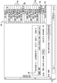
도 6은 시스템을 통해 용접 시스템의 목표 및 성능을 보고하기 위한 예시적인 웹 페이지 뷰(view)이다.
도 7은 이러한 목표를 설정하기 위한 인터페이스를 예시하는 또다른 예시적인 웹 페이지 뷰이다.
도 8은 목표 설정 인터페이스의 부가의 예시적인 웹 페이지 뷰이다.
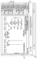
도 9는 특정 용접 또는 시스템의 파라미터를 추적(tracing)하기 위한 인터페이스의 예시적인 웹 페이지 뷰이다.
도 10은 분석 및 제시될 수 있는 이력(historical) 용접들을 열거한 예시적인 웹 페이지 뷰이다.
도 11은 시스템을 통해 이용 가능한 이력 트레이스들(historical traces)의 예시적인 웹 페이지 뷰이다.
도 12는 비교를 위해 시스템 및 시스템 그룹의 선택이 가능한 상태 인터페이스의 예시적인 웹 페이지 뷰이다.
도 13은 도 12의 인터페이스를 통해 선택되는 시스템 및 시스템 그룹의 비교의 예시적인 웹 페이지 뷰이다. These and other features, aspects, and advantages of the present invention will become better understood when the following detailed description is read with reference to the accompanying drawings, in which like characters represent like parts throughout.
BRIEF DESCRIPTION OF THE DRAWINGS Figure 1 is a drawing of an exemplary monitoring system for collecting information, storing information, analyzing information, and presenting analysis results in accordance with aspects of the present disclosure, where it applies to large manufacturing and fabrication entities.
2 is a diagram of a system application to a single or mobile welding system to which the present technique may be applied.
Figure 3 is a drawing of an exemplary cloud-based implementation of the system.
Figure 4 is a drawing of an exemplary welding system of the type that can be monitored and analyzed in accordance with the present technique.
Figure 5 is a drawing of specific functional components of a monitoring and analysis system.
Figure 6 is an exemplary web page view for reporting the objectives and performance of the welding system through the system.
Figure 7 is another exemplary web page view illustrating an interface for setting this goal.
Figure 8 is an additional exemplary web page view of a goal setting interface.
Figure 9 is an exemplary web page view of an interface for tracing parameters of a particular weld or system.
Figure 10 is an exemplary web page view listing historical welds that can be analyzed and presented.
Figure 11 is an exemplary web page view of historical traces available through the system.
Figure 12 is an exemplary web page view of a state interface that allows selection of systems and groups of systems for comparison.
13 is an exemplary web page view of a comparison of systems and groups of systems selected through the interface of FIG.
도 1에 일반적으로 예시된 바와 같이, 모니터링 시스템(10)은 하나 또는 복수의 금속 제작 시스템 및 지원 장비의 모니터링 및 분석을 가능하게 한다. 이러한 관점에서, 복수의 용접 시스템(12 및 14)은, 지원 장비(16)도 그러할 수 있듯이, 상호작용될 수 있다. 용접 시스템 및 지원 장비는, 전반적으로 참조 번호 18로 나타낸 바와 같이, 물리적으로 그리고/또는 분석적으로 그룹핑될 수 있다. 이러한 그룹핑은 강화된 데이터 수집, 데이터 분석, 비교 등을 가능하게 할 수 있다. 아래에 보다 상세하게 기재되는 바와 같이, 그룹핑이 물리적이지 않은 곳까지도(즉, 시스템들이 물리적으로 서로 가까이 위치되어 있지 않음), 본 기술의 사용을 통해 언제든지 매우 유연한 그룹핑이 형성될 수 있다. 예시된 실시예에서, 장비는 참조 번호 20으로 나타낸 바와 같이 구역(department) 또는 위치로 더 그룹핑될 수 있다. 참조 번호 22로 나타낸 바와 같이 다른 구역 및 위치가 마찬가지로 연관될 수 있다. 당해 기술 분야에서의 숙련자라면 알 수 있듯이, 정교한 제조 및 제작 개체에 있어서, 상이한 위치, 설비, 공장, 플랜트 등이 동일 국가의 다양한 부분에 또는 국제적으로 위치될 수 있다. 본 기술은 그의 위치에 관계없이 모든 이러한 시스템들로부터 시스템 데이터의 수집을 가능하게 한다. 더욱이, 이러한 구역, 위치 및 다른 장비 세트로의 그룹핑은 장비의 실제 위치에 관계없이 매우 유연하다.As generally illustrated in FIG. 1, the
일반적으로, 도 1에 나타낸 바와 같이, 시스템은 모니터링/분석 시스템(24)을 포함하며, 모니터링/분석 시스템(24)은 모니터링 용접 시스템 및 지원 장비와 통신하고, 원할 때에 이들로부터 정보를 모을 수 있다. 정보에 액세스하고 정보를 수집하기 위한 다수의 상이한 시나리오를 떠오를 수 있다. 예를 들어, 특정 용접 시스템 및 지원 장비는, 용접 파라미터 데이터의 수집을 가능하게 하는 센서, 제어 회로, 피드백 회로 등을 구비할 것이다. 이러한 시스템의 일부 세부사항이 아래에 기재된다. 예를 들어, 아크 온(arc on) 시간과 같은 시스템 파라미터가 분석되는 경우에, 용접 아크가 확립될 때 및 용접 아크가 유지되는 시간을 반영하는 데이터가 각각의 시스템에서 수집될 수 있다. 전류 및 전압이 일반적으로 감지될 것이고, 이들을 나타내는 데이터가 저장될 것이다. 그라인더, 라이트, 포지셔너, 픽스처 등과 같은 지원 장비에 대하여, 전류, 스위치 클로저 등과 같은 상이한 파라미터가 모니터링될 수 있다. Generally, as shown in FIG. 1, the system includes a monitoring /
언급한 바와 같이, 많은 시스템들은 이러한 데이터를 수집하고 시스템 자체 내에 데이터를 저장할 수 있을 것이다. 다른 시나리오에서, 수집되는 데이터를 적어도 어느 정도 중앙 집중화할 수 있는 로컬 네트워크, 컴퓨터 시스템, 서버, 공유 메모리 등이 제공될 것이다. 명확하게 하기 위하여 이러한 네트워크 및 지원 컴포넌트는 도 1에 예시되지 않는다. 그러면, 모니터링/분석 시스템(24)은 이 정보를 직접 시스템으로부터 또는 데이터를 자체적으로 수집하고 저장하는 임의의 지원 컴포넌트로부터 수집할 수 있다. 데이터는 통상적으로 시스템 명칭, 시스템 유형, 시간 및 날짜, 부품 및 용접 사양, 적용가능한 경우 오퍼레이터 및/또는 시프트 식별정보 등과 같은 식별 정보로 태그될 것이다. 많은 이러한 파라미터들이 정기적으로 모니터링되고 시스템에 유지될 수 있다. 모니터링/분석 시스템(24)은 자체적으로 이러한 정보를 저장할 수 있고, 또는 외부 메모리를 이용할 수도 있다.As mentioned, many systems will be able to collect this data and store the data within the system itself. In other scenarios, a local network, computer system, server, shared memory, etc., may be provided that can centralize the data to be collected at least to some extent. For clarity, these network and support components are not illustrated in FIG. The monitoring /
아래에 보다 충분히 기재되는 바와 같이, 시스템은 하나 이상의 오퍼레이터 인터페이스(26)를 통해 정보의 그룹핑, 정보의 분석, 및 정보의 프리젠테이션(presentation)을 가능하게 한다. 많은 경우에, 오퍼레이터 인터페이스는 종래의 컴퓨터 워크스테이션, 핸드헬드 디바이스, 태블릿 컴퓨터, 또는 임의의 기타 적합한 인터페이스를 포함할 수 있다. 다수의 상이한 디바이스 플랫폼들이 수용될 수 있으며, 유용한 인터페이스, 분석, 보고 등을 포함한 웹 페이지가 브라우저와 같은 범용 인터페이스로 제시될 것으로 현재 고려된다. 상이한 디바이스 플랫폼들은 상이한 데이터 전송 및 디스플레이 표준을 사용할 수 있지만, 시스템은 일반적으로 플랫폼에 관계없이 사용가능하며(platform-agnostic), 모니터링 및 분석된 데이터의 보고 및 요약이 요청되어 데스크톱 워크스테이션, 랩톱 컴퓨터, 태블릿 컴퓨터, 핸드헬드 디바이스 및 전화 등과 같은 임의의 다양한 디바이스 상에 제시될 수 있게 하는 것으로 고려된다. 시스템은, 예를 들어 사용자 이름, 패스워드 등을 프롬프트하는 것에 의한, 확인 및 인증 특징을 포함할 수 있다. As will be described more fully below, the system enables information grouping, information analysis, and presentation of information via one or
시스템은 광범위한 용접 시스템 유형, 시나리오, 응용 및 개수에 대해 설계될 수 있다. 도 1은 대형 제조 및 제작 설비 또는 개체에서 일어날 수 있는 시나리오를 예시하고 있지만, 시스템은 수많은 더 작은 응용 및 심지어는 개인 용접기에게도 동등하게 잘 적용될 수 있다. 도 2에 도시된 바와 같이, 예를 들어, 개별적으로 그리고 이동식 설정으로 동작하는 용접기까지도 수용될 수 있다. 도 2에 예시된 응용은 트럭 또는 작업 차량에 제공된 엔진 구동형 발전기/용접기(28)이다. 이들 시나리오에서, 데이터는 여러 메커니즘 중 하나에 의해 수집될 수 있는 것으로 고려된다. 용접기 자체는 그 자신의 통신 회로를 통해 무선으로 데이터를 전송할 수 있고, 또는 차량 내의 통신 회로, 스마트폰, 태블릿 또는 랩톱 컴퓨터 등과 같이 용접 시스템에 접속된 디바이스를 통해 데이터를 통신할 수 있다. 시스템은 또한, 지정된 위치에 도달할 때 데이터 수집 포인트에 테더링될 수 있다. 도 2의 예시에서, 플래시 드라이브와 같은 분리식 메모리 디바이스(30)가 제공될 수 있으며, 이는 시스템으로부터 정보를 수집하고 정보를 모니터링/분석 시스템(32)으로 이동시킬 수 있다. 이 유형의 더 작은 응용에서, 시스템은 특히 감소된 데이터 세트 및 분석에 대해 설계될 수 있으며, 이는 관련된 용접 오퍼레이터 및 개체에게 보다 유용할 것이다. 그러면, 시스템은 광범위한 이용 사례 중 어떠한 것에든 스케일링 및 적응될 수 있다는 것이 당해 기술 분야에서의 숙련자에게 명백해야 할 것이다.The system can be designed for a wide range of welding system types, scenarios, applications and numbers. While FIG. 1 illustrates scenarios that may occur in a large manufacturing and fabrication facility or entity, the system may equally well be applied to numerous smaller applications and even to personal welders. As shown in Fig. 2, for example, welders operating individually and in a mobile setting can also be accommodated. The application illustrated in Figure 2 is an engine driven generator /
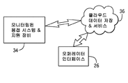
도 3은 예를 들어 클라우드 기반인 예시적인 구현을 예시한다. 이 구현은 현재 데이터 수집, 저장, 및 분석이, 예를 들어 가입 또는 선불 서비스 기반으로, 원격으로 수행되는 많은 시나리오에 대하여 고려된다. 여기에서, 모니터링되는 용접 시스템 및 지원 장비(34)는 하나 이상의 클라우드 데이터 저장 및 서비스 개체(36)와 직접 및 간접적으로 통신한다. 개체들은 임의의 원하는 형태를 취할 수 있고, 이러한 서비스에 있어서 상당한 향상이 일어나는 중이며 앞으로도 계속해서 그러할 것이다. 예를 들어, 제3자 프로바이더가, 시스템으로부터 정보를 수집하고 정보를 현장 외에 저장하고 아래에 기재된 분석 및 보고를 가능하게 하는 정보에 대한 처리를 수행하도록 제작 또는 제조 개체와 계약할 수 있을 것으로 고려된다. 오퍼레이터 인터페이스(26)는 상기 설명한 바와 유사할 수 있지만, 통상적으로 클라우드 기반 서비스에 대한 웹사이트로 어드레싱될 것이다("히트"). 그러면, 인증에 이어서, 원하는 모니터링, 분석 및 프리젠테이션을 가능하게 하는 웹 페이지가 제공될 수 있다. 따라서, 클라우드 기반의 서비스는, 통신 디바이스, 메모리 디바이스, 서버, 데이터 프로세싱 및 분석 하드웨어 및 소프트웨어 등과 같은 컴포넌트를 포함할 것이다. Figure 3 illustrates an exemplary implementation that is cloud based, for example. This implementation is contemplated for many scenarios where current data collection, storage, and analysis are performed remotely, e.g., on a subscription or prepaid service basis. Here, the monitored welding system and supporting
상기 언급한 바와 같이, 용접 시스템의 많은 상이한 유형 및 구성이 본 기술에 의해 수용될 수 있다. 용접 분야에서의 숙련자라면, 특정한 이러한 시스템이 산업계 전반에 걸쳐 표준이 되었다는 것을 용이하게 알 수 있을 것이다. 이들은 예를 들어, 몇몇을 언급하자면 일반적으로 GMAW(gas metal arc welding), GTAW(gas tungsten gas arc welding), SMAW(shielded metal arc welding), SAW(submerged arc welding), 레이저, 및 스터드 용접 시스템으로 지칭되는 시스템을 포함한다. 모든 이러한 시스템들은 금속을 적어도 부분적으로 용융 및 융합시키기 위해 워크피스 및 전극에의 에너지 인가에 의존한다. 시스템은 용가재(filler metal)와 함께 또는 용가재 없이 사용될 수 있지만, 산업계에서 일반적인 대부분의 시스템은 기계 또는 수동 공급형인 일부 형태의 용가재를 사용한다. 더욱이, 특정 시스템은 금속이 아닌 다른 재료와 함께 사용될 수 있고, 이들 시스템도 적절한 경우에 본 기술에 의해 서비스되도록 의도된다.As mentioned above, many different types and configurations of welding systems can be accommodated by the present technique. Those of skill in the welding arts will readily recognize that certain such systems have become a standard throughout the industry. These include, for example, gas metal arc welding (GMAW), gas tungsten arc arc welding (GTAW), shielded metal arc welding (SMAW), submerged arc welding (SAW), laser, and stud welding systems Quot; system " All such systems rely on energy to the workpiece and the electrodes to at least partially melt and fuse the metal. Systems can be used with or without filler metal, but most systems in the industry use some form of filler, either mechanical or manual feed. Moreover, certain systems may be used with materials other than metals, and these systems are also intended to be serviced by this technology where appropriate.
단지 예로써, 도 4는 예시적인 용접 시스템(12), 이 경우 MIG 용접 시스템을 예시한다. 시스템은, 예를 들어 발전기 또는 전력망으로부터 들어오는 전력을 수신하고 들어오는 전력을 용접 전력으로 변환하는 전원 공급 장치를 포함한다. 전력 변환 회로(38)는 이러한 변환을 가능하게 하며, 통상적으로 용접 프로세스 및 절차에 의해 정의되는 대로 교류(AC), 직류, 펄스형 또는 기타 파형을 제공하도록 제어되는 파워 전자 디바이스를 포함할 것이다. 전력 변환 회로는 통상적으로 제어 및 프로세싱 회로(40)에 의해 제어될 것이다. 이러한 회로는, 용접 프로세스 정의, 오퍼레이터 설정 파라미터 등을 저장하는 메모리(별도로 도시되지 않음)에 의해 지원될 것이다. 통상의 시스템에서, 이러한 파라미터는 오퍼레이터 인터페이스(42)를 통해 설정될 수 있다. 시스템은 참조 번호 44로 나타낸 바와 같이 일부 유형의 데이터 또는 네트워크 인터페이스를 포함할 것이다. 많은 이러한 시스템에서, 이 회로는 전원 공급 장치에 포함될 것이지만, 별도의 디바이스에 위치될 수 있다. 시스템은 용접 동작의 수행, 제어 및 실제 데이터 둘 다의 수집(예를 들어, 전압, 전류, 와이어 공급 속도 등의 피드백)을 가능하게 한다. 원하는 경우에, 특정한 이 데이터는 분리식 메모리(46)에 저장될 수 있다. 그러나, 많은 시스템에서, 정보는 제어 및 프로세싱 회로(40)를 지원하는 동일 메모리 디바이스에 저장될 것이다. By way of example only, FIG. 4 illustrates an
MIG 시스템의 경우에, 별도의 와이어 공급기(48)가 제공될 수 있다. 와이어 공급기의 컴포넌트들은 여기에서 점선으로 예시되어 있는데, 일부 시스템이 선택적으로 와이어 공급기를 사용할 수 있기 때문이다. 또다시, 예시된 시스템은 단지 예시적인 것으로만 의도되는 것이다. 이러한 와이어 공급기는, 통상적으로 이용되는 경우에, 용접 와이어 전극 와이어(50)의 스풀, 및 구동 제어 회로(54)의 제어 하에 와이어를 접촉 및 구동시키는 구동 메커니즘(52)을 포함한다. 구동 제어 회로는 종래의 방식으로 원하는 와이어 공급 속도를 제공하도록 설정될 수 있다. 통상의 MIG 시스템에서, 가스 밸브(56)는 실드(shield) 및 가스의 유동 제어를 가능하게 할 것이다. 와이어 공급기에 대한 설정은 오퍼레이터 인터페이스(58)를 통해 이루어질 수 있다. 용접 와이어, 가스, 및 전력은, 도면에서 참조 번호 60으로 나타낸 바와 같은 용접 케이블, 및 리턴 케이블(가끔은 그라운드 케이블로 지칭됨)(62)에 의해 제공된다. 리턴 케이블은 일반적으로 클램프를 통해 워크피스에 연결되며, 용접 케이블을 통해 파워, 와이어 및 가스가 용접 토치(64)에 공급된다.In the case of the MIG system, a
여기에서 또다시, 도 4의 시스템은 단지 예시적인 것임을 유의하여야 하며, 본 기술은 이들 유형의 컷팅, 가열, 및 용접 시스템 뿐만 아니라 다른 것들의 성능의 모니터링 및 분석을 가능하게 한다. 실제로, 동일 모니터링 분석 시스템은 상이한 유형, 메이커, 크기, 및 버전의 금속 제작 시스템으로부터의 데이터를 수집할 수 있다. 수집 및 분석된 데이터는, 동일하거나 상이한 시스템에 대한 상이한 프로세스 및 용접 절차와 관련될 수 있다. 더욱이, 상기에 설명한 바와 같이, 데이터는 금속 제작 시스템 내에서, 시스템 주변에서 또는 시스템과 함께 사용되는 지원 장비로부터 수집될 수 있다. Here again, it should be noted that the system of FIG. 4 is merely exemplary, and this technique enables monitoring and analysis of the performance of these types of cutting, heating, and welding systems as well as others. Indeed, the same monitoring and analysis system can collect data from different types, manufacturers, sizes, and versions of metal fabrication systems. The collected and analyzed data may be associated with different processes and welding procedures for the same or different systems. Moreover, as described above, the data can be collected within the metal fabrication system, around the system, or from the supporting equipment used with the system.
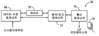
도 5는 통상적으로 모니터링/분석 시스템에서 발견될 수 있는 특정 기능 컴포넌트들을 예시한다. 도 5에 사용된 표기에서, 이들 컴포넌트들은 클라우드 기반의 서비스 개체에 위치될 것이지만, 유사한 컴포넌트가 시스템 구현 중의 임의의 구현에 포함될 수 있다. 컴포넌트는 예를 들어 시스템 및 개체로부터 데이터를 수신하는 데이터 수집 컴포넌트(68)를 포함할 수 있다. 데이터 수집 컴포넌트는, 시스템과의 데이터 교환을 프롬프트(prompt)함으로써 데이터를 "풀(pull)"할 수 있거나, 또는 프롬프트없이 데이터가 시스템에 의해 데이터 수집 컴포넌트에 제공되는 "푸시(push)" 기반으로 작업할 수 있다(예를 들어, 용접 시스템, 네트워크 디바이스, 또는 장비가 접속되어 있는 관리 시스템의 시작시에). 데이터 수집은 임의의 원하는 빈도로 또는 주기적이지 않은 시점에 일어날 수 있다. 예를 들어, 데이터는 용접 동작이 수행될 때에 비정기적으로 수집될 수 있거나, 또는 예를 들어 시프트 기반으로, 매일, 매주, 또는 단순히 용접 오퍼레이터 또는 설비 관리 팀에 의해 원하는 대로, 데이터가 주기적으로 제공될 수 있다. 시스템은 또한, 시스템으로부터 수집된 원시(raw) 데이터 및/또는 처리된 데이터를 저장하는 메모리(70)를 포함할 것이다. 분석/보고 컴포넌트(72)는, 원시 데이터의 프로세싱, 및 결과적인 분석을 시스템, 개체, 그룹, 용접 오퍼레이터 등과 연관시키는 것을 가능하게 한다. 분석 및 보고 컴포넌트 동작의 예는 아래에 보다 상세하게 제공된다. 마지막으로, 통신 컴포넌트(74)는 보고 및 인터페이스 페이지를 분석의 결과로 파퓰레이팅하는 것을 가능하게 한다. 광범위한 이러한 페이지가 도 5에서 참조 번호 76으로 나타낸 바와 같이 제공될 수 있으며, 이의 일부가 아래에 상세하게 기재된다. 따라서 통신 컴포넌트(74)는 다양한 서버, 모뎀, 인터넷 인터페이스, 웹 페이지 정의 등을 포함할 수 있다. Figure 5 illustrates certain functional components that may typically be found in a monitoring / analysis system. In the notation used in FIG. 5, these components will be located in a cloud-based service entity, but similar components may be included in any implementation of the system implementation. The component may include, for example, a
상기 언급한 바와 같이, 본 기술은 광범위한 데이터가 셋업, 구성, 저장, 분석, 추적, 모니터링, 비교 등을 위해 용접 시스템 및 지원 장비로부터 수집될 수 있게 한다. 현재 고려되는 실시예에서, 이 정보는 일련의 인터페이스 페이지들로 요약되며, 이는 범용 브라우저에 제공되어 범용 브라우저 상에서 볼 수 있는 웹 페이지로서 구성될 수 있다. 그러나, 실제로, 임의의 적합한 인터페이스가 사용될 수 있다. 하지만, 범용 브라우저 및 유사한 인터페이스의 사용으로 인해, 데이터가 상기 언급한 바와 같이 고정 워크스테이션, 기업 시스템 뿐만 아니라 이동식 및 휴대형 디바이스를 포함하는 임의의 광범위한 디바이스 플랫폼 및 상이한 유형의 디바이스에 지원될 수 있다. 도 6 내지 도 13은 다양한 사용자에 대하여 제공될 수 있는 예시적인 인터페이스 페이지를 예시한다. As noted above, this technology allows a wide range of data to be gathered from the welding system and supporting equipment for setup, configuration, storage, analysis, tracking, monitoring, comparison, and the like. In the presently contemplated embodiment, this information is summarized as a series of interface pages, which may be provided as a web page that is provided to a general purpose browser and viewable on a general purpose browser. However, in practice, any suitable interface may be used. However, due to the use of general purpose browsers and similar interfaces, data may be supported on any of a wide variety of device platforms and different types of devices, including mobile and portable devices as well as fixed workstations, enterprise systems, as mentioned above. Figures 6-13 illustrate exemplary interface pages that may be provided for various users.
먼저 도 6을 참조하면, 목표 보고 페이지(78)가 예시되어 있다. 이 페이지는, 하나 이상의 용접 시스템 및 지원 장비 명칭 뿐만 아니라 시스템에 대하여 설정된 목표에 기초한 성능 분석의 디스플레이를 가능하게 한다. 도 6에 예시된 페이지에서, 다수의 용접 시스템 및 지원 장비는 참조 번호 80으로 나타낸 바와 같이 식별된다. 이들은 참조 번호 82로 나타낸 바와 같이 그룹들로 연관될 수 있다. 실제로, 본 개시에서 설명되는 모든 분석에 내재된 데이터는 개별 시스템과 연관되어 있다. 그러면 인터페이스 툴에 의해 이들은 서로 자유롭게 연관될 수 있다. 예시된 예에서, 위치 또는 구역(84)이 위치 내에 지정된 여러 그룹들로 생성되었다. 그러면, 이들 그룹의 각각은 도면에 도시된 바와 같이 하나 이상의 용접 시스템 및 임의의 기타 장비를 포함할 수 있다. 본 실시예는 이들 시스템의 자유로운 연관을 가능하게 하며, 그리하여 개별 시스템, 시스템 그룹, 위치 등의 유용한 분석이 수행될 수 있다. 시스템 및 지원 장비는 단일 물리적 근접범위 내에 있을 수 있지만, 이는 반드시 그러한 것은 아니다. 그룹들은 예를 들어 시스템 유형, 작업 스케줄, 생산 및 제품 등에 기초하여 생성될 수 있다. 오퍼레이터가 개인 식별 정보를 제공하는 시스템에서, 이 정보는 시스템 정보에 추가하여 또는 시스템 정보 대신에 추적될 수 있다. Referring first to FIG. 6, a
예시된 실시예에서, 모니터링되는 시스템 및 장비의 현재 동작 상태를 전달하기 위한 상태 표시자(indicator)가 예시되어 있다. 참조 번호 86으로 지정된 바와 같은 이들 표시자는 예를 들어, 활성(ACTIVE) 시스템, 유휴(IDLE) 시스템, 접속해제(DISCONNECTED) 시스템, 오류(ERROR), 통지(NOTIFICATIONS) 등을 표시할 수 있다. 시스템 상태가 실시간으로 또는 거의 실시간 기반으로 모니터링될 수 있는 경우, 이러한 표시자는 장비의 현재 상태에 대해 관리 요원에게 유용한 피드백을 제공할 수 있다. 도 6에 예시된 특정 정보는 본 구현에서 목표(GOALS) 탭(88)을 선택(예를 들어, 클릭)함으로써 얻어진다. 제시되는 정보는, 참조 번호 90으로 나타낸 바와 같이 연속 사용 주간(WEEK)과 같은, 유용한 시간 슬롯 또는 지속기간에서 연관될 수 있다. 예를 들어, 매시간, 매일, 매주, 매달, 시프트 기반의 지정 등과 같은 임의의 적합한 기간이 이용될 수 있다. In the illustrated embodiment, a status indicator for communicating the current operating state of the monitored system and equipment is illustrated. These indicators, as designated by
페이지(78)는 또한, 선택된 시스템 또는 시스템들에 대하여 설정된 목표에 기초하여 다양한 성능 기준들 각각의 분석의 결과를 제시한다. 예시된 예에서, 용접 시스템은 좌측의 장비 트리에서 체크 마크에 의해 표시된 바와 같이 선택되었고, 여러 기준에 기초한 성능이 막대 그래프 형태로 제시되어 있다. 이 예에서, 아크 온(ARC ON) 시간, 퇴적(DEPOSITION), 아크 시작(ART START), 스패터(SPATTER), 및 그라인딩 시간(GRINDING TIME)과 같은 다수의 모니터링 기준이 표시된다. 목표는 아래에 설명되는 바와 같이 특정 시스템에 대하여 설정되었고, 이 목표에 비교한 시스템의 성능이 각각의 모니터링된 파라미터에 대하여 막대에 의해 표시된다. 특정한 파라미터는 관례상 긍정정일 수 있는 반면, 다른 것은 부정적일 수 있음을 유의하여야 한다. 즉, 예로써, 용접 아크가 확립 및 유지되는 작업 시간 부분을 나타내는 아크 온 시간에 대하여, 설정된 표준을 초과하는 목표 퍼센티지는 유리하거나 바람직할 수 있다. 스패터와 같은 다른 파라미터의 경우, 목표를 초과하는 것이 실제로 작업 품질에 해로울 수 있다. 아래에 설명되는 바와 같이, 본 구현은 분석 및 프리젠테이션이 이들을 관례상 긍정적인 것으로 간주하는지 아니면 관례상 부정적인 것으로 간주하는지의 지정을 가능하게 한다. 결과적인 프리젠테이션(84)은 미리 확립된 목표에 비교하여 실제 성능을 용이하게 시각화하는 것을 가능하게 한다. The
도 7은 예시적인 목표 편집(EDIT GOAL) 페이지(96)를 예시한다. 표준 또는 일반적으로 사용되는 목표, 또는 특정 목적을 위한 특정 목표의 설정을 가능하게 하는 특정 필드가 제공될 수 있다. 예를 들어, 목표의 명칭이 필드(98)에서 지정될 수 있다. 이 명칭에 관련된 다른 정보는 동일하거나 상이한 시스템을 분석하는 데 사용하기 위해 저장될 수 있다. 참조 번호 100으로 나타낸 바와 같이, 예시된 페이지는 아크 온 시간과 같은, 목표에 대한 표준을 설정하는 것을 가능하게 한다. 원하는 표준을 직접적으로 아니면 간접적으로 나타내는 데이터가 수집될 수 있는 한, 다른 표준 및 파라미터가 지정될 수 있다(즉, 비교 및 프리젠테이션을 위한 값의 확립이 가능함). 목표에 대한 관례는 참조 번호 102로 나타낸 바와 같이 설정될 수 있다. 즉, 상기 설명한 바와 같이, 원하거나 유리할 수 있는 특정 목표, 확립된 목표가 목표로 하는 최대 값을 정의하는 반면에, 다른 목표는 목표로 하는 최소 값을 확립할 수 있다. 그러면, 예를 들어 수치 퍼센티지 기반으로, 목적(예를 들어, 단위) 기반으로, 상대적 기반으로, 또는 임의의 다른 유용한 기반으로, 타겟(TARGET)(104)이 확립될 수 있다. 시프트(SHIFT) 필드(106)와 같은 부가의 필드가 제공될 수 있다. 또한, 일부 구현에서, 행한 것으로 알려진 예시적인 용접으로 목표 또는 표준 설정을 시작하고 수락가능한 특성을 소유하는 것이 유용할 수 있다. 그러면, 목표는 표준으로서 이것으로 또는 이 용접에 기초하여 설정된 하나 이상의 파라미터로 설정될 수 있다(예를 들어, +/-20%).FIG. 7 illustrates an example
도 8은 도 7에 예시된 바와 같은 페이지에 의해 설정된 확립된 목표를 취하고 이들을 특정 장비에 적용할 수 있는 목표 설정 페이지(108)를 예시한다. 도 8의 페이지(108)에서, "하부 용접기(BOTTOM WELDER)"로 지정된 용접 시스템이 좌측에 체크 마크에 의해 표시된 바와 같이 선택되었다. 시스템 식별정보가(110)가 페이지에 나타난다. 그러면, 목표 또는 표준의 메뉴가 참조 번호 112로 나타낸 바와 같이 디스플레이된다. 이 예에서, 선택은, 장비에 어떠한 목표도 두지 않기(NONE), 특정 위치(또는 다른 논리적 그룹핑)에 대하여 설정된 특정 목표를 이어받기(INHERIT GOALS FROM BUILDING 32 USING NONE), 미리 정의된 목표(예를 들어, 따라서 도 7에 도시된 바와 같은 페이지에 의해 확립된 목표)를 선택하기(SELECT A PREDEFINED GOAL), 및 장비에 대한 맞춤 목표를 확립하기(CUSTOM)를 포함한다. FIG. 8 illustrates a
본 기술은 또한, 추적(tracking) 또는 트레이스(trace) 뷰(view)에서 시스템의 특정 성능 파라미터를 저장 및 분석하는 것을 가능하게 한다. 이들 뷰는, 특정 용접, 특정한 기간에 걸친 성능, 특정 오퍼레이터에 의한 성능, 특정 작업 또는 부분에 대한 성능 등에 관련하여 매우 유익할 수 있다. 예시적인 용접 트레이스 페이지(114)가 도 9에 예시되어 있다. 이 페이지 상에 표시된 바와 같이, 페이지의 좌측에 나타낸 바와 같은 다양한 장비가 선택될 수 있으며, 참조 번호 116으로 나타낸 바와 같이 하나의 특정 시스템이 현재 선택되어 있다. 선택되면, 이 구현에서, 이 특정 시스템에 관련된 다양한 데이터가 참조 번호 118로 나타낸 바와 같이 디스플레이된다. 이 정보는 시스템으로부터, 또는 시스템에 대해 보관된 데이터로부터, 예를 들어 조직 내에서, 클라우드 자원 등 내에서, 인출될 수 있다. 참조 번호 120으로 나타낸 바와 같이 특정한 통계 데이터가 통합되어 디스플레이될 수 있다. The technique also makes it possible to store and analyze certain performance parameters of the system in a tracking or a trace view. These views can be very beneficial in terms of specific welding, performance over a specific period, performance by a particular operator, performance for a particular job or part, and the like. An exemplary
용접 트레이스 페이지는 또한, 특히 관심있을 수 있는 특정한 모니터 파라미터의 트레이스들의 그래픽 프리젠테이션을 포함한다. 용접 트레이스 섹션(122)은, 이 예에서, 수평 액세스(126)를 따라 시간의 함수로서 그래프가 그려진 여러 파라미터(124)를 도시한다. 이 특정 예에서, 파라미터는 와이어 공급 속도, 전류, 및 볼트를 포함한다. 이 예에 케이스가 예시되어 있는 용접은 대략 8초의 지속기간을 갖는다. 이 시간 동안, 모니터링된 파라미터가 변하며 이들 파라미터를 반영하는 데이터가 샘플링되고 저장되었다. 그러면 각각의 파라미터에 대한 개별 트레이스(128)가 생성되어 사용자에게 제시된다. 또한, 이 예에서 "마우스 오버(mouse over)" 또는 기타 입력에 의해, 시스템은 참조 번호 130으로 나타낸 바와 같이 특정 시점에서 하나 이상의 파라미터에 대한 특정 값을 디스플레이할 수 있다. The weld trace page also includes a graphical presentation of the traces of the particular monitor parameter that may be of particular interest. The
트레이스 페이지는, 본 개시에서 설명되는 임의의 페이지에서와 같이, 미리 또는 사용자에 의한 요구시, 파퓰레이팅될 수 있다. 이러한 경우에 따라, 임의의 수의 시스템 및 특정 용접에 대한 트레이스 페이지가 추후 분석 및 프리젠테이션을 위해 저장될 수 있다. 따라서 도 10에 예시된 바와 같은 이력(HISTORY) 페이지(132)가 컴파일될 수 있다. 예시된 이력 페이지에서, 선택된 시스템(116)(또는 선택된 시스템들의 조합)에 대해 수행된 용접 리스트가 참조 번호 134에 의해 나타낸 바와 같이 제시된다. 이들 용접은 시간, 시스템, 지속기간, 용접 파라미터 등에 의해 식별될 수 있다. 더욱이, 이러한 리스트는 특정 오퍼레이터, 특정 제품 및 제작품 등에 대하여 컴파일될 수 있다. 예시된 실시예에서, 참조 번호 136으로 나타낸 바와 같이 특정 용접이 사용자에 의해 선택되었다. The trace page may be populated, either in advance or as required by the user, as in any page described in this disclosure. In this case, any number of systems and trace pages for a particular weld may be stored for later analysis and presentation. Thus, a
도 11은 특정 용접(136)의 선택에 이어 디스플레이될 수 있는 이력 트레이스 페이지(138)를 예시한다. 이 관점에서, 시스템의 식별정보는 참조 번호 140으로 나타낸 바와 같이 시간 및 날짜와 함께 제공된다. 여기에서 또다시, 모니터링된 파라미터는 참조 번호 124로 나타낸 바와 같이 식별되고, 시간 축(126)이 제공되며 이를 따라 트레이스들(128)이 디스플레이된다. 당해 기술 분야의 숙련자라면 알 수 있듯이, 이러한 분석을 저장하고 컴파일할 수 있는 능력은 시스템 성능, 오퍼레이터 성능, 특정 부품에 대한 성능, 구역 및 설비의 성능 등을 평가하는데 있어서 상당히 유용할 수 있다. FIG. 11 illustrates a
또한, 본 기술은 다양한 범위 기반으로 장비들 간의 비교를 가능하게 한다. 실제로, 시스템들이 비교될 수 있고, 비교로부터의 결과인 프리젠테이션들이 이러한 비교를 위한 베이스를 형성할 수 있는 임의의 적합한 파라미터에 대해 제공될 수 있다. 예시적인 비교 선택 페이지(142)가 도 12에 예시되어 있다. 이 페이지에 도시된 바와 같이, 복수의 시스템들(80)은 또다시 설비 또는 위치(84)에 대한 그룹들(82)로 그룹핑된다. 상태 표시자(86)가 개별 시스템 또는 그룹에 대하여 제공될 수 있다. 도 12에 예시된 상태 페이지는 그 다음, 도 13에 예시된 바와 같이 비교를 위한 시스템을 선택하기 위한 베이스로서 작용할 수 있다. 여기에서, 동일한 시스템 및 그룹이 선택 및 비교에 이용 가능하다. 비교 페이지(144)는 이들 시스템을 디스플레이하고, 사용자가 마음대로 생성되는 개별 시스템, 그룹 또는 임의의 하부그룹을 클릭하거나 선택할 수 있게 한다. 즉, 시스템의 전체 그룹이 선택될 수 있는 반면, 사용자는 참조 번호 146으로 나타낸 바와 같이 개별 시스템 또는 개별 그룹을 선택할 수 있다. 비교 섹션(148)이 제공되며, 비교 섹션(148)에서 매시간(HOURLY), 매일(DAILY), 매주(WEEKLY), 매달(MONTHLY), 또는 임의의 다른 범위와 같은 비교를 위한 시간 베이스가 선택될 수 있다. 선택되면, 원하는 파라미터가 개별 시스템에 대하여 비교되는데, 시스템은 참조 번호 152로 나타낸 바와 같이 식별되고, 비교가 행해지며 이 경우에 참조 번호 154로 나타낸 바와 같이 그래프로 디스플레이된다. 예시된 예에서는, 예를 들어, 시스템 온(system on) 시간이 비교를 위한 베이스로서 선택되었다. 시스템의 각자의 온 시간을 나타내는 각각의 개별 시스템에 대한 데이터가 분석되고 수평 막대에 의해 퍼센티지 기반으로 제시되었다. 예를 들어, 선택된 파라미터에 기반하여 하나의 시스템이 다른 시스템을 능가하였음을 표시하는 것과 같이, 다른 비교가 시스템들 사이에 직접 행해질 수 있다. 특정 실시예에서 하나보다 많은 파라미터가 선택될 수 있고, 이들은 원시 값, 처리되거나 계산된 값에 기초할 수 있다. In addition, this technology enables comparison between devices based on a wide range. In practice, the systems can be compared and presentations resulting from the comparison can be provided for any suitable parameter that can form the basis for such comparison. An exemplary
본 발명의 특정 특징만 여기에 예시되고 기재되었지만, 당해 기술 분야에서의 숙련자에게 많은 수정 및 변경이 떠오를 것이다. 따라서, 첨부된 청구항은 모든 이러한 수정 및 변경을 본 발명의 진정한 사상 내에 속하는 것으로 포함하도록 의도됨을 이해하여야 한다. While only certain features of the invention have been illustrated and described herein, many modifications and changes will occur to those skilled in the art. It is, therefore, to be understood that the appended claims are intended to cover all such modifications and changes as fall within the true spirit of the invention.
Claims (20)
웹 기반의 시스템을 통해, 복수의 금속 제작 자원에 대해 수행되는 금속 제작 동작들의 파라미터를 나타내는 데이터에 액세스하는 단계;
적어도 하나의 컴퓨터 프로세서를 통해, 상기 금속 제작 자원의 성능을 비교하기 위해 상기 복수의 금속 제작 자원의 각각에 대하여 파라미터를 분석하는 단계;
상기 적어도 하나의 컴퓨터 프로세서를 통해, 상기 분석을 나타내는 그래픽 표시(indicia)로, 사용자가 볼 수 있는(user viewable) 보고 페이지를 파퓰레이팅(populating)하는 단계; 및
웹 기반의 시스템을 통해, 상기 사용자가 볼 수 있는 보고 페이지를 사용자에게 전송하는 단계
를 포함하는, 금속 제작 자원 성능 비교 방법. In a method for comparing the performance of a metal fabrication resource,
Accessing, via a web-based system, data representing parameters of metal fabrication operations performed on a plurality of metal fabrication resources;
Analyzing parameters for each of the plurality of metal fabrication resources to compare capabilities of the metal fabrication resources through at least one computer processor;
Populating a user viewable report page with graphical indicia indicative of the analysis via the at least one computer processor; And
Transmitting, through the web-based system, a report page viewable by the user to the user
And comparing the performance of the metal fabrication resource.
동작시에, 복수의 금속 제작 자원의 금속 제작 동작들의 파라미터를 나타내는 데이터에 액세스하는 웹 기반의 통신 컴포넌트;
동작시에, 상기 금속 제작 자원의 성능을 비교하기 위해 상기 파라미터를 분석하고, 상기 금속 제작 자원의 각각에 대한 분석을 나타내는 그래픽 표시로, 사용자가 볼 수 있는 보고 페이지를 파퓰레이팅하는 적어도 하나의 컴퓨터 프로세서; 및
동작시에, 상기 사용자가 볼 수 있는 보고 페이지를 사용자에게 전송하는 웹 기반의 전송 컴포넌트
를 포함하는, 금속 제작 자원 성능 비교 시스템. In a metal production resource performance comparison system,
A web based communication component that, in operation, accesses data representing parameters of metal fabrication operations of a plurality of metal fabrication resources;
At least one computer for analyzing said parameters to compare the performance of said metal fabrication resources in operation and graphically displaying an analysis of each of said metal fabrication resources, A processor; And
In operation, a web-based transport component that sends a report page viewable by the user to a user
And a metal production resource performance comparison system.
웹 기반의 시스템에 의해 컴파일되고 전달되며, 사용자 시청 디바이스로 전송되는 컴퓨터 실행 코드에 의해 정의된, 적어도 하나의 사용자가 볼 수 있는 보고 페이지를 포함하고,
상기 보고 페이지는, 복수의 금속 제작 자원, 관심있는 기간, 및 상기 관심있는 기간 동안 금속 제작 자원에 대해 수행된 금속 제작 동작들의 파라미터의 적어도 하나의 그래픽 표시 - 상기 그래픽 표시는 금속 제작 자원의 성능을 비교함 - 를 식별하는, 사용자가 볼 수 있는 표시를 포함하는 것인, 금속 제작 자원 성능 비교 인터페이스. In the metal fabrication resource performance comparison interface,
A report page that is compiled and delivered by a web based system and is viewable by at least one user defined by computer executable code that is transmitted to a user viewing device,
Wherein the reporting page comprises at least one graphical representation of a plurality of metal fabrication resources, a period of interest, and parameters of metal fabrication operations performed on the metal fabrication resources during the period of interest, Wherein the comparison includes an indication that the user can see, identifying the comparison.
Applications Claiming Priority (3)
| Application Number | Priority Date | Filing Date | Title |
|---|---|---|---|
| US13/838,541 | 2013-03-15 | ||
| US13/838,541 US9665093B2 (en) | 2013-03-15 | 2013-03-15 | Welding resource performance comparison system and method |
| PCT/US2014/017862 WO2014143532A1 (en) | 2013-03-15 | 2014-02-22 | Welding resource performance comparison system and method |
Publications (1)
| Publication Number | Publication Date |
|---|---|
| KR20150129655A true KR20150129655A (en) | 2015-11-20 |
Family
ID=50349826
Family Applications (1)
| Application Number | Title | Priority Date | Filing Date |
|---|---|---|---|
| KR1020157017864A KR20150129655A (en) | 2013-03-15 | 2014-02-22 | Welding resource performance comparison system and method |
Country Status (10)
| Country | Link |
|---|---|
| US (3) | US9665093B2 (en) |
| EP (1) | EP2972618A1 (en) |
| JP (1) | JP2016512171A (en) |
| KR (1) | KR20150129655A (en) |
| AU (2) | AU2014228545A1 (en) |
| BR (1) | BR112015015882A2 (en) |
| CA (1) | CA2892520C (en) |
| DE (1) | DE202014011418U1 (en) |
| MX (1) | MX350860B (en) |
| WO (1) | WO2014143532A1 (en) |
Families Citing this family (13)
| Publication number | Priority date | Publication date | Assignee | Title |
|---|---|---|---|---|
| US9862051B2 (en) | 2011-09-27 | 2018-01-09 | Illinois Tool Works Inc. | Welding system and method utilizing cloud computing and data storage |
| US9665093B2 (en) * | 2013-03-15 | 2017-05-30 | Illinois Tool Works Inc. | Welding resource performance comparison system and method |
| US9704140B2 (en) | 2013-07-03 | 2017-07-11 | Illinois Tool Works Inc. | Welding system parameter comparison system and method |
| US10558953B2 (en) | 2013-07-03 | 2020-02-11 | Illinois Tool Works Inc. | Welding system parameter comparison system and method |
| US11103948B2 (en) | 2014-08-18 | 2021-08-31 | Illinois Tool Works Inc. | Systems and methods for a personally allocated interface for use in a welding system |
| US10242317B2 (en) | 2014-11-25 | 2019-03-26 | Illinois Tool Works Inc. | System for estimating the amount and content of fumes |
| US11022952B2 (en) | 2015-01-02 | 2021-06-01 | Illinois Tool Works Inc. | System and method for enhancing manufacturing efficiency via operator activity detection |
| US11131978B2 (en) | 2015-12-28 | 2021-09-28 | Illinois Tool Works Inc. | Systems and methods for analyzing manufacturing parameters |
| JP6409831B2 (en) * | 2016-08-08 | 2018-10-24 | 住友電気工業株式会社 | Management device and management program |
| US10896289B2 (en) * | 2017-10-18 | 2021-01-19 | Bently Nevada, Llc | Event list management system |
| US11267065B2 (en) * | 2019-02-18 | 2022-03-08 | Lincoln Global, Inc. | Systems and methods providing pattern recognition and data analysis in welding and cutting |
| US11768483B2 (en) | 2019-05-22 | 2023-09-26 | Illinois Tool Works Inc. | Distributed weld monitoring system with job tracking |
| US11400537B2 (en) | 2019-09-12 | 2022-08-02 | Illinois Tool Works Inc. | System and methods for labeling weld monitoring time periods using machine learning techniques |
Family Cites Families (42)
| Publication number | Priority date | Publication date | Assignee | Title |
|---|---|---|---|---|
| US4825038A (en) | 1987-08-10 | 1989-04-25 | The United States Of America As Represented By The United States Department Of Energy | Method for controlling gas metal arc welding |
| JPH1147950A (en) | 1997-07-28 | 1999-02-23 | Miyachi Technos Corp | Remote welding control equipment |
| KR100256665B1 (en) | 1997-10-07 | 2000-05-15 | 이종묵 | Spot welding monitoring system |
| AT501741B1 (en) | 1999-08-16 | 2006-11-15 | Fronius Int Gmbh | WELDING DEVICE WITH COMMUNICATION INTERFACE AND METHOD FOR OPERATING THE WELDING DEVICE |
| US20150121309A1 (en) | 2000-02-17 | 2015-04-30 | George Reed | Selection interface systems, structures, devices and methods |
| AT412076B (en) | 2000-12-15 | 2004-09-27 | Fronius Schweissmasch Prod | METHOD FOR CONNECTING SEVERAL WELDING DEVICES AND WELDING DEVICE THEREFOR |
| US6624388B1 (en) * | 2001-01-25 | 2003-09-23 | The Lincoln Electric Company | System and method providing distributed welding architecture |
| US6486439B1 (en) | 2001-01-25 | 2002-11-26 | Lincoln Global, Inc. | System and method providing automated welding information exchange and replacement part order generation |
| US6552303B1 (en) | 2001-05-29 | 2003-04-22 | Lincoln Global, Inc. | System for enabling arc welders |
| US6636776B1 (en) | 2001-07-09 | 2003-10-21 | Lincoln Global, Inc. | System and method for managing welding procedures and welding resources |
| US6639182B2 (en) | 2001-09-19 | 2003-10-28 | Illinois Tool Works Inc. | Pendant control for a welding-type system |
| JP2003211378A (en) | 2002-01-18 | 2003-07-29 | Yaskawa Electric Corp | Work information processor |
| EP1519807A1 (en) | 2002-07-04 | 2005-04-06 | Fronius International GmbH | Method for operating a welding device, and one such welding device |
| US6744011B1 (en) | 2002-11-26 | 2004-06-01 | General Motors Corporation | Online monitoring system and method for a short-circuiting gas metal arc welding process |
| US6940039B2 (en) | 2003-12-22 | 2005-09-06 | Lincoln Global, Inc. | Quality control module for tandem arc welding |
| US7908302B1 (en) | 2004-09-17 | 2011-03-15 | Symantec Operating Corporation | In-place splitting and merging of files |
| US7643890B1 (en) | 2005-01-13 | 2010-01-05 | Lincoln Global, Inc. | Remote management of portable construction devices |
| AT502326B1 (en) * | 2005-09-09 | 2009-07-15 | Fronius Int Gmbh | REMOTE ACCESS UNIT AND COMMUNICATION METHOD FOR MANAGING WELDING DEVICES |
| CN100451171C (en) | 2005-09-27 | 2009-01-14 | 北京东方新材科技有限公司 | Surface treatment for improving metal welding performance and work pieces therefrom |
| US8190282B2 (en) | 2006-06-09 | 2012-05-29 | Hitachi, Ltd. | Work management apparatus, picking carriage, work performance collection system, rework measurement system, workability management system, rework measurement measuring method, work performance collection method, workability management method and workability management program |
| US20080078811A1 (en) | 2006-09-15 | 2008-04-03 | The Lincoln Electric Company | Weld data acquisition |
| US9104195B2 (en) | 2006-12-20 | 2015-08-11 | Lincoln Global, Inc. | Welding job sequencer |
| EP1958738B1 (en) | 2007-02-13 | 2013-08-14 | Abb Research Ltd. | Remote diagnostic system for robots |
| GB2454232B (en) | 2007-11-01 | 2012-04-25 | Validation Ct Tvc Ltd | Welding support system |
| US9442481B2 (en) | 2008-01-09 | 2016-09-13 | Illinois Tool Works Inc. | Automatic weld arc monitoring system |
| EP2248099B1 (en) | 2008-02-22 | 2019-04-10 | Murata Machinery, Ltd. | Vao productivity suite |
| US8847115B2 (en) | 2008-06-16 | 2014-09-30 | Illinois Tool Works Inc. | Configurable welding interface for automated welding applications |
| US20090327035A1 (en) | 2008-06-28 | 2009-12-31 | Microsoft Corporation | Media content service for renting jukeboxes and playlists adapted for personal media players |
| US8592722B2 (en) | 2008-11-03 | 2013-11-26 | Illinois Tool Works Inc. | Weld parameter interface |
| US8274013B2 (en) | 2009-03-09 | 2012-09-25 | Lincoln Global, Inc. | System for tracking and analyzing welding activity |
| US7970830B2 (en) | 2009-04-01 | 2011-06-28 | Honeywell International Inc. | Cloud computing for an industrial automation and manufacturing system |
| US20100299185A1 (en) | 2009-05-20 | 2010-11-25 | Caro Ricardo J | Diagnostic Tools and Methods Thereof |
| US9230449B2 (en) | 2009-07-08 | 2016-01-05 | Lincoln Global, Inc. | Welding training system |
| US8569646B2 (en) | 2009-11-13 | 2013-10-29 | Lincoln Global, Inc. | Systems, methods, and apparatuses for monitoring weld quality |
| US8706282B2 (en) | 2010-01-12 | 2014-04-22 | Ford Global Technologies, Llc | Weldability prediction and recommendation systems and methods |
| EP2585975B1 (en) | 2010-06-28 | 2018-03-21 | Precitec GmbH & Co. KG | A method for classifying a multitude of images recorded by a camera observing a processing area and laser material processing head using the same |
| KR101186668B1 (en) | 2010-08-18 | 2012-09-27 | 고종철 | Remote monitoring system for welding |
| US9015173B2 (en) * | 2011-02-01 | 2015-04-21 | Honda Motor Co., Ltd. | Spot weld data management and monitoring system |
| US9053221B2 (en) | 2011-03-04 | 2015-06-09 | International Business Machines Corporation | Promotion of performance parameters in distributed data processing environment |
| US9862051B2 (en) | 2011-09-27 | 2018-01-09 | Illinois Tool Works Inc. | Welding system and method utilizing cloud computing and data storage |
| CN102922089B (en) | 2012-08-13 | 2014-10-29 | 天津大学 | Welding process information acquisition and quality monitoring device and method based on Ethernet |
| US9665093B2 (en) * | 2013-03-15 | 2017-05-30 | Illinois Tool Works Inc. | Welding resource performance comparison system and method |
-
2013
- 2013-03-15 US US13/838,541 patent/US9665093B2/en active Active
-
2014
- 2014-02-22 AU AU2014228545A patent/AU2014228545A1/en not_active Abandoned
- 2014-02-22 EP EP14712373.1A patent/EP2972618A1/en not_active Ceased
- 2014-02-22 DE DE202014011418.8U patent/DE202014011418U1/en not_active Expired - Lifetime
- 2014-02-22 WO PCT/US2014/017862 patent/WO2014143532A1/en active Application Filing
- 2014-02-22 CA CA2892520A patent/CA2892520C/en active Active
- 2014-02-22 BR BR112015015882A patent/BR112015015882A2/en not_active IP Right Cessation
- 2014-02-22 JP JP2016500346A patent/JP2016512171A/en active Pending
- 2014-02-22 KR KR1020157017864A patent/KR20150129655A/en not_active IP Right Cessation
- 2014-02-22 MX MX2015006640A patent/MX350860B/en active IP Right Grant
-
2016
- 2016-09-22 AU AU2016231591A patent/AU2016231591A1/en not_active Abandoned
-
2017
- 2017-05-16 US US15/596,393 patent/US10282693B2/en active Active
-
2019
- 2019-05-07 US US16/405,487 patent/US10885489B2/en active Active
Also Published As
| Publication number | Publication date |
|---|---|
| CN105164596A (en) | 2015-12-16 |
| MX350860B (en) | 2017-09-19 |
| US10282693B2 (en) | 2019-05-07 |
| US10885489B2 (en) | 2021-01-05 |
| MX2015006640A (en) | 2015-11-16 |
| US20140278242A1 (en) | 2014-09-18 |
| DE202014011418U1 (en) | 2020-04-28 |
| BR112015015882A2 (en) | 2017-07-11 |
| JP2016512171A (en) | 2016-04-25 |
| AU2016231591A1 (en) | 2016-10-13 |
| AU2014228545A1 (en) | 2015-07-02 |
| US20190266543A1 (en) | 2019-08-29 |
| CA2892520C (en) | 2018-07-24 |
| US20170249578A1 (en) | 2017-08-31 |
| US9665093B2 (en) | 2017-05-30 |
| CA2892520A1 (en) | 2014-09-18 |
| WO2014143532A1 (en) | 2014-09-18 |
| EP2972618A1 (en) | 2016-01-20 |
Similar Documents
| Publication | Publication Date | Title |
|---|---|---|
| KR102295274B1 (en) | Welding resource performance goal system and method | |
| US10885489B2 (en) | Welding resource performance comparison system and method | |
| US9684303B2 (en) | Welding resource tracking and analysis system and method | |
| KR102245109B1 (en) | Welding system parameter comparison system and method | |
| KR102257260B1 (en) | Welding system data management system and method |
Legal Events
| Date | Code | Title | Description |
|---|---|---|---|
| A201 | Request for examination | ||
| AMND | Amendment | ||
| E902 | Notification of reason for refusal | ||
| AMND | Amendment | ||
| E601 | Decision to refuse application | ||
| X091 | Application refused [patent] | ||
| AMND | Amendment | ||
| X601 | Decision of rejection after re-examination |