JP2016512171A - Welding resource performance comparison system and method - Google Patents
Welding resource performance comparison system and method Download PDFInfo
- Publication number
- JP2016512171A JP2016512171A JP2016500346A JP2016500346A JP2016512171A JP 2016512171 A JP2016512171 A JP 2016512171A JP 2016500346 A JP2016500346 A JP 2016500346A JP 2016500346 A JP2016500346 A JP 2016500346A JP 2016512171 A JP2016512171 A JP 2016512171A
- Authority
- JP
- Japan
- Prior art keywords
- user
- metal fabrication
- resources
- metal
- viewable
- Prior art date
- Legal status (The legal status is an assumption and is not a legal conclusion. Google has not performed a legal analysis and makes no representation as to the accuracy of the status listed.)
- Pending
Links
- 238000000034 method Methods 0.000 title claims description 31
- 238000003466 welding Methods 0.000 title abstract description 62
- 238000004519 manufacturing process Methods 0.000 claims abstract description 61
- 229910052751 metal Inorganic materials 0.000 claims abstract description 54
- 239000002184 metal Substances 0.000 claims abstract description 54
- 238000004458 analytical method Methods 0.000 claims description 42
- 238000004891 communication Methods 0.000 claims description 9
- 238000013500 data storage Methods 0.000 claims description 3
- 230000005540 biological transmission Effects 0.000 claims description 2
- 230000008021 deposition Effects 0.000 claims description 2
- 230000000977 initiatory effect Effects 0.000 claims 1
- 230000007704 transition Effects 0.000 claims 1
- 238000012544 monitoring process Methods 0.000 description 17
- 238000013480 data collection Methods 0.000 description 8
- 238000010586 diagram Methods 0.000 description 5
- 230000008569 process Effects 0.000 description 5
- 238000012545 processing Methods 0.000 description 5
- 238000006243 chemical reaction Methods 0.000 description 4
- 238000007726 management method Methods 0.000 description 4
- 230000006870 function Effects 0.000 description 3
- 239000000463 material Substances 0.000 description 3
- 230000007246 mechanism Effects 0.000 description 3
- 230000002354 daily effect Effects 0.000 description 2
- 238000007405 data analysis Methods 0.000 description 2
- 239000000945 filler Substances 0.000 description 2
- 238000012986 modification Methods 0.000 description 2
- 230000004048 modification Effects 0.000 description 2
- 230000008439 repair process Effects 0.000 description 2
- 238000007778 shielded metal arc welding Methods 0.000 description 2
- 230000003442 weekly effect Effects 0.000 description 2
- 238000005520 cutting process Methods 0.000 description 1
- 230000001627 detrimental effect Effects 0.000 description 1
- 238000005516 engineering process Methods 0.000 description 1
- 230000003203 everyday effect Effects 0.000 description 1
- 238000010438 heat treatment Methods 0.000 description 1
- 150000002739 metals Chemical class 0.000 description 1
- 230000008520 organization Effects 0.000 description 1
- 230000000737 periodic effect Effects 0.000 description 1
- 238000012552 review Methods 0.000 description 1
- 238000003860 storage Methods 0.000 description 1
- 239000000126 substance Substances 0.000 description 1
- 238000012546 transfer Methods 0.000 description 1
- WFKWXMTUELFFGS-UHFFFAOYSA-N tungsten Chemical compound [W] WFKWXMTUELFFGS-UHFFFAOYSA-N 0.000 description 1
- 229910052721 tungsten Inorganic materials 0.000 description 1
- 239000010937 tungsten Substances 0.000 description 1
- 238000012795 verification Methods 0.000 description 1
- 238000012800 visualization Methods 0.000 description 1
Images


Classifications
-
- G—PHYSICS
- G06—COMPUTING; CALCULATING OR COUNTING
- G06Q—INFORMATION AND COMMUNICATION TECHNOLOGY [ICT] SPECIALLY ADAPTED FOR ADMINISTRATIVE, COMMERCIAL, FINANCIAL, MANAGERIAL OR SUPERVISORY PURPOSES; SYSTEMS OR METHODS SPECIALLY ADAPTED FOR ADMINISTRATIVE, COMMERCIAL, FINANCIAL, MANAGERIAL OR SUPERVISORY PURPOSES, NOT OTHERWISE PROVIDED FOR
- G06Q10/00—Administration; Management
- G06Q10/06—Resources, workflows, human or project management; Enterprise or organisation planning; Enterprise or organisation modelling
- G06Q10/063—Operations research, analysis or management
- G06Q10/0639—Performance analysis of employees; Performance analysis of enterprise or organisation operations
- G06Q10/06398—Performance of employee with respect to a job function
-
- B—PERFORMING OPERATIONS; TRANSPORTING
- B23—MACHINE TOOLS; METAL-WORKING NOT OTHERWISE PROVIDED FOR
- B23K—SOLDERING OR UNSOLDERING; WELDING; CLADDING OR PLATING BY SOLDERING OR WELDING; CUTTING BY APPLYING HEAT LOCALLY, e.g. FLAME CUTTING; WORKING BY LASER BEAM
- B23K26/00—Working by laser beam, e.g. welding, cutting or boring
- B23K26/02—Positioning or observing the workpiece, e.g. with respect to the point of impact; Aligning, aiming or focusing the laser beam
- B23K26/06—Shaping the laser beam, e.g. by masks or multi-focusing
-
- B—PERFORMING OPERATIONS; TRANSPORTING
- B23—MACHINE TOOLS; METAL-WORKING NOT OTHERWISE PROVIDED FOR
- B23K—SOLDERING OR UNSOLDERING; WELDING; CLADDING OR PLATING BY SOLDERING OR WELDING; CUTTING BY APPLYING HEAT LOCALLY, e.g. FLAME CUTTING; WORKING BY LASER BEAM
- B23K26/00—Working by laser beam, e.g. welding, cutting or boring
- B23K26/20—Bonding
- B23K26/21—Bonding by welding
-
- B—PERFORMING OPERATIONS; TRANSPORTING
- B23—MACHINE TOOLS; METAL-WORKING NOT OTHERWISE PROVIDED FOR
- B23K—SOLDERING OR UNSOLDERING; WELDING; CLADDING OR PLATING BY SOLDERING OR WELDING; CUTTING BY APPLYING HEAT LOCALLY, e.g. FLAME CUTTING; WORKING BY LASER BEAM
- B23K9/00—Arc welding or cutting
- B23K9/095—Monitoring or automatic control of welding parameters
- B23K9/0953—Monitoring or automatic control of welding parameters using computing means
-
- B—PERFORMING OPERATIONS; TRANSPORTING
- B23—MACHINE TOOLS; METAL-WORKING NOT OTHERWISE PROVIDED FOR
- B23K—SOLDERING OR UNSOLDERING; WELDING; CLADDING OR PLATING BY SOLDERING OR WELDING; CUTTING BY APPLYING HEAT LOCALLY, e.g. FLAME CUTTING; WORKING BY LASER BEAM
- B23K9/00—Arc welding or cutting
- B23K9/10—Other electric circuits therefor; Protective circuits; Remote controls
- B23K9/1006—Power supply
- B23K9/1043—Power supply characterised by the electric circuit
-
- B—PERFORMING OPERATIONS; TRANSPORTING
- B23—MACHINE TOOLS; METAL-WORKING NOT OTHERWISE PROVIDED FOR
- B23K—SOLDERING OR UNSOLDERING; WELDING; CLADDING OR PLATING BY SOLDERING OR WELDING; CUTTING BY APPLYING HEAT LOCALLY, e.g. FLAME CUTTING; WORKING BY LASER BEAM
- B23K9/00—Arc welding or cutting
- B23K9/16—Arc welding or cutting making use of shielding gas
- B23K9/173—Arc welding or cutting making use of shielding gas and of a consumable electrode
-
- G—PHYSICS
- G05—CONTROLLING; REGULATING
- G05B—CONTROL OR REGULATING SYSTEMS IN GENERAL; FUNCTIONAL ELEMENTS OF SUCH SYSTEMS; MONITORING OR TESTING ARRANGEMENTS FOR SUCH SYSTEMS OR ELEMENTS
- G05B23/00—Testing or monitoring of control systems or parts thereof
- G05B23/02—Electric testing or monitoring
- G05B23/0205—Electric testing or monitoring by means of a monitoring system capable of detecting and responding to faults
- G05B23/0208—Electric testing or monitoring by means of a monitoring system capable of detecting and responding to faults characterized by the configuration of the monitoring system
- G05B23/0216—Human interface functionality, e.g. monitoring system providing help to the user in the selection of tests or in its configuration
-
- Y—GENERAL TAGGING OF NEW TECHNOLOGICAL DEVELOPMENTS; GENERAL TAGGING OF CROSS-SECTIONAL TECHNOLOGIES SPANNING OVER SEVERAL SECTIONS OF THE IPC; TECHNICAL SUBJECTS COVERED BY FORMER USPC CROSS-REFERENCE ART COLLECTIONS [XRACs] AND DIGESTS
- Y04—INFORMATION OR COMMUNICATION TECHNOLOGIES HAVING AN IMPACT ON OTHER TECHNOLOGY AREAS
- Y04S—SYSTEMS INTEGRATING TECHNOLOGIES RELATED TO POWER NETWORK OPERATION, COMMUNICATION OR INFORMATION TECHNOLOGIES FOR IMPROVING THE ELECTRICAL POWER GENERATION, TRANSMISSION, DISTRIBUTION, MANAGEMENT OR USAGE, i.e. SMART GRIDS
- Y04S10/00—Systems supporting electrical power generation, transmission or distribution
- Y04S10/50—Systems or methods supporting the power network operation or management, involving a certain degree of interaction with the load-side end user applications
Abstract
ウェブベースのシステムを介して、溶接システム等の金属製作システム及び関連機器を解析することができ、溶接動作中にシステムからのパラメーターデータを収集することによってパフォーマンスを比較することができる。データは記憶され、ユーザーによって要求されると解析される。関心対象のシステム及びシステムグループの選択を可能にするユーザー閲覧可能ページを提供することができる。比較の基準として用いられるパラメーターも選択することができる。選択に基づいて、比較を示すページを生成し、ユーザーに送信することができる。Through a web-based system, metal fabrication systems such as welding systems and related equipment can be analyzed, and performance can be compared by collecting parameter data from the system during the welding operation. Data is stored and analyzed as requested by the user. A user-viewable page can be provided that allows the selection of systems and system groups of interest. Parameters used as a basis for comparison can also be selected. Based on the selection, a page showing the comparison can be generated and sent to the user.
Description
本発明は、包括的には、溶接システムと、溶接動作のための支援機器とに関する。特に、本発明は、溶接リソースのパフォーマンスの監視及び解析による比較の技法に関する。 The present invention relates generally to welding systems and assistive devices for welding operations. In particular, the invention relates to a technique for comparison by monitoring and analyzing the performance of welding resources.
様々な製造、修復及び他の用途のために、多岐にわたる溶接システムが補助機器及び支援機器とともに開発されている。例えば、溶接システムは、部品、構造体及び部分構造体、支持構造体、並びに多くの構成部品を組み立てるために産業全体にわたって普及している。これらのシステムは、手動、自動又は半自動とすることができる。現代の製作及び製造エンティティは、多数の溶接システムを用いることができ、これらの溶接システムは、ロケーション、タスク、ジョブ等によってグループ化することができる。時折、より小規模な作業が溶接システムを用いる場合があるが、それでもこれらは多くの場合に溶接システムの動作にとって重要である。幾つかのエンティティ及び個人の場合、溶接システムは固定とすることもできるし、移動式とし、カート、トラック及び修理車両に搭載すること等もできる。これらのシナリオの全てにおいて、パフォーマンス判断基準を設定し、パフォーマンスを監視し、パフォーマンスを解析し、可能であればパフォーマンスをオペレーター及び/又は管理チーム及び技術者に報告することがますます有用となっている。そのような解析によって、数ある用途の中でも、リソースの計画、価格及び利益性の決定、リソースのスケジューリング、企業全体の説明責任が可能になる。 A wide variety of welding systems have been developed with auxiliary and support equipment for various manufacturing, repair and other applications. For example, welding systems are prevalent throughout the industry to assemble parts, structures and substructures, support structures, and many components. These systems can be manual, automatic or semi-automatic. Modern fabrication and manufacturing entities can use a number of welding systems, which can be grouped by location, task, job, etc. Occasionally, smaller operations may use the welding system, but these are still often important to the operation of the welding system. For some entities and individuals, the welding system can be fixed, mobile, mounted on carts, trucks and repair vehicles, and so on. In all of these scenarios, it becomes increasingly useful to set performance criteria, monitor performance, analyze performance, and report performance to operators and / or management teams and technicians where possible. Yes. Such analysis enables resource planning, price and profitability determination, resource scheduling, and enterprise accountability, among other applications.
しかしながら、溶接システムパフォーマンスを収集、記憶、解析及び報告するように設計されたシステムは、容易にかつ有効に利用される域まで達していない。幾つかのエンティティでは、溶接、溶接品質、並びにシステム及び作業者のパフォーマンスの制限された追跡が利用可能である場合がある。しかしながら、これらは通常、大規模な解析、追跡又は比較を一切可能にしていない。そのようなツールにおける改善が必要である。より詳細には、データが1つ又は複数のロケーションにおいて1つ又は複数のシステムから収集され、解析が行われ、同じロケーション又は他のロケーションにおいてレポートが生成され提示されることを可能にする改善が有用であろう。他の改善には、パフォーマンスを遡及的に見直し、目標並びに複数のグループ及びエンティティにわたる同様のシステムと比較したパフォーマンスを見る機能が含まれ得る。 However, systems designed to collect, store, analyze and report welding system performance have not reached the point where they are easily and effectively utilized. For some entities, limited tracking of welds, weld quality, and system and worker performance may be available. However, they usually do not allow any large scale analysis, tracking or comparison. Improvements in such tools are needed. More specifically, improvements that allow data to be collected from one or more systems at one or more locations, analyzed, and reports generated and presented at the same or other locations. Will be useful. Other improvements may include the ability to review performance retroactively and see performance compared to similar systems across targets and groups and entities.
本開示は、そのような需要に応えるように設計されたシステム及び方法を示す。本開示の或る特定の態様によれば、金属製作リソースのパフォーマンス比較方法は、ウェブベースシステムを介して、複数の金属製作リソースにおいて実行される金属製作動作のパラメーターを表すデータにアクセスすることを含む。少なくとも1つのコンピュータープロセッサを介して、複数の金属製作リソースのそれぞれについてパラメーターを解析して金属製作リソースのパフォーマンスが比較され、ユーザー閲覧可能レポートページが、解析を表す図形表示を用いて作成される。次に、ウェブベースのシステムを介して、ユーザー閲覧可能レポートページがユーザーに送信される。 The present disclosure shows systems and methods designed to meet such demand. According to certain aspects of the present disclosure, a method for comparing metal fabrication resource performance includes accessing data representing parameters of metal fabrication operations performed on a plurality of metal fabrication resources via a web-based system. Including. Via at least one computer processor, parameters for each of the plurality of metal fabrication resources are analyzed to compare the performance of the metal fabrication resources, and a user viewable report page is created using a graphical display representing the analysis. A user viewable report page is then sent to the user via the web-based system.
金属製作リソースのパフォーマンス比較システムも開示される。このシステムは、動作時に、複数の金属製作リソースの金属製作動作のパラメーターを表すデータにアクセスするウェブベースの通信コンポーネントを備える。少なくとも1つのコンピュータープロセッサが、パラメーターを解析して金属製作リソースのパフォーマンスを比較し、ユーザー閲覧可能レポートページを、金属製作リソースのそれぞれの解析を表す図形表示を用いて作成する。ウェブベースの送信コンポーネントがユーザー閲覧可能レポートページをユーザーに移行する。 A performance comparison system for metal fabrication resources is also disclosed. The system includes a web-based communication component that, in operation, accesses data representing parameters of metal fabrication operations of a plurality of metal fabrication resources. At least one computer processor analyzes the parameters to compare the performance of the metal fabrication resources, and creates a user-viewable report page with a graphical representation representing each analysis of the metal fabrication resources. A web-based submission component migrates user-viewable report pages to users.
本発明のこれらの特徴、態様及び利点並びに他の特徴、態様及び利点は、同様の符号が図全体を通して同様の部品を表す添付の図面を参照しながら以下の詳細な記載を読めば、よりよく理解されることであろう。 These features, aspects and advantages of the present invention, as well as other features, aspects and advantages will be better understood when the following detailed description is read with reference to the accompanying drawings in which like numerals represent like parts throughout the drawings. It will be understood.
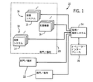
図1に包括的に示すように、監視システム10は、1つ又は複数の金属製作システム及び支援機器の監視及び解析を可能にする。この図において、複数の溶接システム12、14とインタラクトすることができ、支援機器16ともインタラクトすることができる。溶接システム及び支援機器は、包括的に参照符号18によって示されるように物理的に及び/又は解析的にグループ化することができる。そのようなグループ化によって、データ収集、データ解析、比較等を向上させることができる。以下でより詳細に説明するように、グループ化が物理的でない(すなわち、システムが物理的に互いの近くに位置していない)場合であっても、本技法を用いることにより、任意の時点において柔軟性の高いグループ化を形成することができる。図示される実施形態では、機器は、参照符号20によって示されるように、部門又はロケーションにおいて更にグループ化される。参照符号22によって示されるような他の部門及びロケーションも同様に関連付けすることができる。当業者であれば理解するように、最新の製作及び製造エンティティでは、異なるロケーション、施設、工場、設備等を同じ国の様々な地域に、又は国をまたがって配置することができる。本技法は、全てのそのようなシステムから、それらのシステムのロケーションにかかわらず、システムデータを収集することを可能にする。さらに、そのような部門、ロケーション及び他の機器組へのグループ化は、機器の実際のロケーションにかかわらず柔軟性が高い。
As comprehensively shown in FIG. 1, the
図1に示されているように、一般的に、システムは、監視溶接システム及び支援機器と通信し、所望に応じてこれらから情報を収集することができる監視/解析システム24を備える。情報にアクセスし、情報を収集するための複数の異なるシナリオを構想することができる。例えば、或る特定の溶接システム及び支援機器は、溶接パラメーターデータの収集を可能にするセンサー、制御回路部、フィードバック回路等を設けられる。そのようなシステムの幾つかの詳細が以下で説明される。例えば、アークオン時間等のシステムパラメーターが解析される場合、データは、溶接アークが確立されたとき、及び溶接アークが維持される時間を反映して各システムにおいて収集することができる。電流及び電圧が一般的に検知され、これらを表すデータが記憶される。研磨機、ライト、ポジショナー、固定具等の支援機器の場合、電流、スイッチ閉鎖等の異なるパラメーターを監視することができる。
As shown in FIG. 1, generally, the system comprises a monitoring /
上記のように、多くのシステムは、そのようなデータを収集し、システム自体の中に記憶することができる。他のシナリオでは、収集したデータを少なくとも或る程度まで集中化することができるローカルネットワーク、コンピューターシステム、サーバー、共有メモリ等が設けられる。明確にするために、そのようなネットワーク及びサポートコンポーネントは図1に示されていない。次に、監視/解析システム24は、この情報をシステムから直接、又はデータをそれ自体が収集及び記憶する任意のサポートコンポーネントから収集することができる。データは通常、システム名称、システムタイプ、日時、部品及び溶接の詳細、適用可能な場合は作業者及び/又はシフトの識別情報等の識別情報を用いてタグ付けされる。多くのそのようなパラメーターを規則的に監視し、システム内に保持することができる。監視/解析システム24は、それ自体がそのような情報を記憶することもできるし、外部メモリを利用することもできる。
As noted above, many systems can collect such data and store it within the system itself. In other scenarios, a local network, computer system, server, shared memory, etc. are provided that can centralize the collected data at least to some extent. For clarity, such network and support components are not shown in FIG. The monitoring /
以下でより詳細に説明されるように、システムは、1つ又は複数のオペレーターインターフェース26を介して情報のグループ化、情報の解析及び情報の提示を可能にする。多くの場合、オペレーターインターフェースは、従来のコンピューターワークステーション、ハンドヘルドデバイス、タブレットコンピューター又は任意の他の適切なインターフェースを備えることができる。複数の異なるデバイスプラットフォームを収容し得ることも現在検討されており、有用なインターフェース、解析、レポート等を含むウェブページがブラウザー等の汎用インターフェースにおいて提示されることになる。異なるデバイスプラットフォームは異なるデータ送信及び表示規格を用いる場合があるが、システムは概してプラットフォームにとらわれず、監視及び解析されたデータのレポート及びサマリーが、デスクトップワークステーション、ラップトップコンピューター、タブレットコンピューター、ハンドヘルドデバイス及び電話等の多種のデバイスのうちの任意のものにおいて要求され提示されることを可能にすることが検討されている。システムは、ユーザー名、パスワード等の入力を促すこと等による検証及び認証機能を含むことができる。 As will be described in more detail below, the system allows grouping of information, analysis of information, and presentation of information via one or more operator interfaces 26. In many cases, the operator interface may comprise a conventional computer workstation, handheld device, tablet computer or any other suitable interface. The ability to accommodate multiple different device platforms is currently being considered, and a web page containing useful interfaces, analysis, reports, etc. will be presented in a general purpose interface such as a browser. Different device platforms may use different data transmission and display standards, but the system is generally platform independent and reports and summaries of monitored and analyzed data are available for desktop workstations, laptop computers, tablet computers, handheld devices And enabling it to be requested and presented on any of a variety of devices such as telephones. The system can include verification and authentication functions, such as by prompting for user name, password, etc.
システムは多岐にわたる溶接システムタイプ、シナリオ、用途及び数で設計することができる。図1は、大規模な製作又は製造施設又はエンティティにおいて生じ得るシナリオを示しているが、システムは、はるかに小規模の用途、更には個々の溶接機にも等しく良好に適用することができる。図2に示すように、例えば、独立して移動設定で動作する溶接機であっても受け入れることができる。示される図2の用途は、トラック又は作業車両に設けられるエンジン駆動型発電機/溶接機28である。これらのシナリオにおいて、データは幾つかの機構のうちの1つによって収集することができることが検討されている。溶接機自体が独自の通信回路部を介して無線でデータを送信することを可能とすることもできるし、車両、スマートフォン、タブレット又はラップトップコンピューター等の中の通信回路等の、溶接システムに接続されたデバイスを介してデータを通信することもできる。また、システムは、特定のロケーションに到達したときにデータ収集ポイントにつなぐこともできる。図2の例示では、システムから情報を収集し、この情報を監視/解析システム32に移すことができる、フラッシュドライブ等のリムーバブルメモリデバイス30を設けることができる。このタイプのより小規模な用途では、システムは、低減されたデータセット、並びに関与する溶接作業者及びエンティティにより有用である解析のために特に設計することができる。この場合、当業者には、システムを多岐にわたるユースケースのうちの任意のものにスケーリングし、適応させることができることが明らかであるはずである。
The system can be designed with a wide variety of welding system types, scenarios, applications and numbers. Although FIG. 1 illustrates a scenario that may occur in a large scale manufacturing or manufacturing facility or entity, the system can be equally well applied to much smaller applications and even to individual welders. As shown in FIG. 2, for example, a welding machine that operates independently in a moving setting can be accepted. The application shown in FIG. 2 is an engine driven generator /
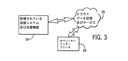
図3は、例えばクラウドベースの例示的な実施態様を示している。この実施態様は、データの収集、記憶及び解析が、加入ベース又は有料サービスベース等で遠隔で行われる多くのシナリオについて現在検討されている。ここで、監視される溶接システム及び支援機器34は、1つ又は複数のクラウドデータ記憶及びサービスエンティティ36と直接及び間接的に通信する。エンティティは任意の所望の形態を取ることができ、そのようなサービスにおける大きな改善が生じており、また今後何年間も生じ続けるであろう。例えば、第三者のプロバイダーが製造又は製作エンティティと接触し、システムから情報を収集し、情報をオフサイトで記憶し、以下で説明する解析及び報告を可能にする情報の処理を行うことができることが検討されている。オペレーターインターフェース26は、上記で論考したものと同様とすることができるが、通常、クラウドベースのサービスのためのウェブサイトに宛てられる(「ヒットする」)。認証に続いて、次に、所望の監視、解析及び提示を可能にするウェブページをサービス提供することができる。したがって、クラウドベースのサービスは、通信デバイス、メモリデバイス、サーバー、データ処理及び解析ハードウェア及びソフトウェア等のコンポーネントを含む。
FIG. 3 shows an exemplary implementation based on, for example, a cloud. This embodiment is currently under consideration for many scenarios where data collection, storage and analysis is done remotely, such as on a subscription basis or a paid service basis. Here, the monitored welding system and
上記のように、本技法によって、多くの異なるタイプ及び構成の溶接システムを受け入れることができる。溶接技術における当業者であれば、或る特定のそのようなシステムは、産業全体にわたる標準となっていることを容易に理解するであろう。これらは、例えば、幾つか例を挙げると、ガスメタルアーク溶接(GMAW)、ガスタングステンガスアーク溶接(GTAW)、シールド金属アーク溶接(SMAW)、サブマージアーク溶接(SAW)、レーザー及びスタッド溶接システムと一般的に呼ばれるシステムを含む。全てのそのようなシステムは、工作物及び電極にエネルギーを印加し、少なくとも部分的に金属を融解及び溶解することに依拠する。システムは溶加材の有無にかかわらず用いることができるが、産業において一般的なほとんどのシステムは、機械又は手動により供給される或る形態の溶加材を用いる。さらに、或る特定のシステムは、金属以外の材料とともに用いることができ、これらのシステムも、適宜本技法によってサービス提供されることが意図される。 As described above, the technique can accommodate many different types and configurations of welding systems. Those skilled in the art of welding technology will readily appreciate that certain such systems have become industry-wide standards. These include, for example, gas metal arc welding (GMAW), gas tungsten gas arc welding (GTAW), shielded metal arc welding (SMAW), submerged arc welding (SAW), laser and stud welding systems, to name a few. Includes a system called All such systems rely on applying energy to the workpiece and electrode to at least partially melt and melt the metal. Although the system can be used with or without filler material, most systems common in the industry use some form of filler material supplied by machine or manually. In addition, certain systems can be used with materials other than metals, and these systems are also intended to be serviced by the techniques as appropriate.
単なる例であるが、図4は、例示的な溶接システム12、この例ではMIG溶接システムを示している。このシステムは、発電機又は電力網等から到来する電力を受信し、この到来する電力を溶接電力に変換する電源を備える。電力変換回路部38はそのような変換を可能にし、通常、溶接プロセス及び手順によって規定されるような交流(AC)波形、直流波形、パルス波形又は他の波形を提供するように制御されるパワーエレクトロニクスデバイスを備える。電力変換回路部は通常、制御及び処理回路部40によって制御される。そのような回路部は、溶接プロセス定義、オペレーター設定パラメーター等を記憶するメモリ(別個には示されない)によってサポートされる。通常のシステムでは、そのようなパラメーターはオペレーターインターフェース42を介して設定することができる。これらのシステムは、参照符号44によって示されるような或るタイプのデータ又はネットワークインターフェースを備える。多くのそのようなシステムでは、この回路部は電源に含まれるが、別個のデバイス内に配置することもできる。このシステムは、溶接動作を実行し、制御データ及び実際のデータ(例えば、電圧、電流、ワイヤ送給速度等のフィードバック)の双方を収集することを可能にする。所望に応じて、このデータのうちの幾つかは、リムーバブルメモリ46内に記憶することができる。一方、多くのシステムにおいて、情報は、制御及び処理回路部40をサポートするのと同じメモリデバイス内に記憶される。
By way of example only, FIG. 4 shows an
MIGシステムの場合、別個のワイヤ送給装置48を設けることができる。ワイヤ送給装置の構成要素はここでは破線で示されている。なぜなら、幾つかのシステムは選択的にワイヤ送給装置を用いる場合があるためである。示されるシステムは、ここでもまた、単なる例示であることが意図される。そのようなワイヤ送給装置は通常、利用されるとき、溶接ワイヤ電極ワイヤのスプール50と、駆動制御回路部54に接触し、駆動制御回路部54の制御下でワイヤを駆動する駆動機構52とを備える。駆動制御回路部は、従来の方法で所望のワイヤ送給速度を提供するように設定することができる。通常のMIGシステムでは、ガス弁56は、シールド及びガスの流れの制御を可能にする。ワイヤ送給装置に対する設定は、オペレーターインターフェース58を介して行うことができる。溶接ワイヤ、ガス及び電力は、参照符号60に図式的に示されるような溶接ケーブルと、帰線ケーブル(アースケーブルと呼ばれる場合もある)62とによって提供される。帰線ケーブルは一般に、クランプを介して工作物に結合され、電力、ワイヤ及びガスが溶接ケーブルを介して溶接トーチ64に供給される。
In the case of a MIG system, a
ここでもまた、図4のシステムは単なる例示であり、本技法は、これらのタイプの切断、加熱及び溶接システム及び他のシステムのパフォーマンスの監視及び解析を可能にすることに留意されたい。実際、同じ監視/解析システムが、異なる型、造り、サイズ及びバージョンの金属製作システムからデータを収集することができる。収集及び解析されるデータは、同じシステム又は異なるシステムの様々なプロセス及び溶接手順に関係することができる。さらに、上記で論考されたように、データは、金属製作システムにおいて、金属製作システムの周囲で、又は金属製作システムとともに用いられる支援機器から収集することができる。 Again, it should be noted that the system of FIG. 4 is merely exemplary, and the present technique allows monitoring and analysis of the performance of these types of cutting, heating and welding systems and other systems. In fact, the same monitoring / analysis system can collect data from different types, builds, sizes and versions of metal fabrication systems. The data collected and analyzed can relate to various processes and welding procedures of the same system or different systems. Further, as discussed above, data can be collected from assistive equipment used in, around, or in conjunction with a metal fabrication system.
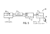
図5は、監視/解析システムにおいて通常見ることができる或る特定の機能コンポーネントを示している。図5において用いられる表記において、これらのコンポーネントはクラウドベースのサービスエンティティ内に配置されるが、システムの実施態様のうちの任意のものに同様のコンポーネントを含めることができる。これらのコンポーネントは、例えば、システム及びエンティティからデータを受信するデータ収集コンポーネント68を含むことができる。データ収集コンポーネントは、システムとのデータ交換を促すことによってデータを「引き出す(pull)」こともできるし、データ交換を促すことなく(例えば、機器が接続される溶接システム、ネットワークデバイス又は管理システムの始動時に)システムによってデータ収集コンポーネントにデータが提供される「プッシュ」ベースで機能することもできる。データ収集は、任意の所望の頻度で、又は周期的でない時点において行うことができる。例えば、データは、溶接動作が行われる際にその時々で収集することもできるし、シフトごと、日ごと、週ごと等、周期的に提供することもできるし、単に溶接作業者又は施設管理チームの要求に応じて提供することもできる。システムは、システムから収集した未処理データ及び/又は処理済みデータを記憶するメモリ70も備える。解析/報告コンポーネント72は、未処理データを処理すること、及び解析結果をシステム、エンティティ、グループ、溶接作業者等と関連付けることを可能にする。解析及び報告コンポーネントの動作の例は、以下でより詳細に与えられる。最後に、通信コンポーネント74は、レポート及びインターフェースページを解析結果により作成することを可能にする。多岐にわたるそのようなページを、図5において参照符号76によって示すように提供することができ、それらのうちの幾つかを以下で詳細に説明する。このため、通信コンポーネント74は、様々なサーバー、モデム、インターネットインターフェース、ウェブページ定義等を含むことができる。
FIG. 5 illustrates certain functional components that are normally visible in a monitoring / analysis system. In the notation used in FIG. 5, these components are located within the cloud-based service entity, but similar components can be included in any of the system implementations. These components can include, for example, a
上記のように、本技法は、設定、構成、記憶、解析、追跡、監視、比較等のために多岐にわたるデータを溶接システム及び支援機器から収集することを可能にする。現在検討されている実施形態では、この情報は、汎用ブラウザーに提供することができ、この汎用ブラウザー上で閲覧することができるウェブページとして構成することができる一連のインターフェースページに要約される。一方、実際は、任意の適切なインターフェースを用いることができる。一方、汎用ブラウザー及び同様のインターフェースの使用は、固定式のワークステーション、企業システムを含むが、上記で言及した移動式デバイス及びハンドヘルドデバイスも含む、任意の広範なデバイスプラットフォーム及び様々なタイプのデバイスにデータをサービス提供することを可能にする。図6〜図13は、広範な使用のために提供することができる例示的なインターフェースページを示している。 As described above, the present technique allows a wide variety of data to be collected from welding systems and support equipment for setup, configuration, storage, analysis, tracking, monitoring, comparison, and the like. In the presently contemplated embodiment, this information is summarized in a series of interface pages that can be provided to a general-purpose browser and configured as web pages that can be viewed on the general-purpose browser. On the other hand, in practice, any suitable interface can be used. On the other hand, the use of general purpose browsers and similar interfaces includes any of a wide variety of device platforms and various types of devices, including stationary workstations, enterprise systems, but also mobile and handheld devices mentioned above. Enables serving data. 6-13 illustrate exemplary interface pages that can be provided for a wide range of uses.
まず図6を参照すると、目標レポートページ78が示される。このページは、1つ又は複数の溶接システム及び支援機器の指定並びにシステムに対して設定された目標に基づくパフォーマンス解析の表示を可能にする。図6に示されるページでは、参照符号80によって示されているように、複数の溶接システム及び支援機器が識別される。これらは、参照符号82に示されるようにグループで関係付けることができる。実際には、本開示において論考される解析の全ての基礎をなすデータは個々のシステムと関連付けられる。これらは、互いに自由に関連付けることができ、その際インターフェースツールによって関連付けることができる。示される例では、ロケーション内で指定された幾つかのグループによりロケーション又は部門84が作成されている。このとき、これらのグループはそれぞれ、図に示す1つ又は複数の溶接システム及び任意の他の機器を含むことができる。本実施形態は、個々のシステム、システムのグループ、ロケーション等の有用な解析を行うことができるように、これらのシステムの自由な関連付けを可能にする。システム及び支援機器は、単一の物理的な近傍にあることができるが、必ずしもそうである必要はない。グループは、例えば、システムタイプ、作業工程、製造及び製品等に基づいて作成することができる。作業者が個人識別情報を与えるシステムでは、この情報を、システム情報に加えて、又はシステム情報の代わりに追跡することができる。
Referring first to FIG. 6, a
示される実施形態において、監視されているシステム及び機器の現在の動作ステータスを伝えるステータスインジケーターが示されている。参照符号86によって指定されているようなこれらのインジケーターは、例えば、アクティブ状態のシステム、アイドル状態のシステム、切断されたシステム、エラー、通知等を示すことができる。システムステータスをリアルタイムベースで又はほぼリアルタイムベースで監視することができる場合、そのようなインジケーターは、機器の現在のステータスに関し、管理人員に有用なフィードバックを提供することができる。本実施態様では、図6に示す特定の情報は、目標タブ88を選択する(例えば、クリックする)ことによって得られる。提示される情報は、参照符号90によって示されるように、連続使用週等の有用なタイムスロット又は持続時間に関連付けることができる。時間ごと、日ごと、週ごと、月ごと、シフトベースの指定等の任意の適切な期間を利用することができる。
In the illustrated embodiment, a status indicator is shown that conveys the current operational status of the system and equipment being monitored. These indicators, as designated by
ページ78は、選択された1つ又は複数のシステムに対して設定された目標に基づいて広範のパフォーマンス判断基準のそれぞれのパフォーマンス判断基準の解析結果も提示する。示される例では、或る溶接システムが、左側の機器ツリーにおけるチェックマークによって示されるように選択されており、幾つかの判断基準に基づくパフォーマンスがバーチャートの形態で提示されている。この例では、アークオン時間、堆積、アーク開始、スパッター及び研削時間等の複数の監視される判断基準が示されている。以下で論考するように、特定のシステムに対する目標が設定されており、この目標と比較したシステムのパフォーマンスが、監視されるパラメーターごとにバーによって示されている。これらのパラメーターによっては、取り決めにおいて肯定的であり得るものもあるし、否定的であり得るものもあることに留意されたい。すなわち、例として、溶接アークが確立され維持される作動時間の部分を表すアークオン時間の場合、設定された標準を超える目標のパーセンテージが有利であるか又は望ましい場合がある。スパッター等の他のパラメーターの場合、目標を超えることは実際、作業品質に対し有害である場合がある。以下で論考するように、本実施態様は、解析及び提示がこれらを取り決めに従って肯定的であるとみなし得るか又は否定的であるとみなし得るかの指定を可能にする。結果の提示94によって、予め確立した目標と比較して、実際のパフォーマンスを容易に視覚化することが可能になる。
図7は、例示的な目標編集ページ96を示している。標準的な若しくは一般的に用いられる目標、又は特定の目的のための特定の目標を設定することを可能にする或る特定のフィールドを提供することができる。例えば、フィールド98において目標名を指定することができる。この目標名に関する他の情報を、同じシステム又は異なるシステムを解析する際に用いるために記憶することができる。参照符号100によって示されるように、示されているページは、アークオン時間等の目標の標準を設定することを可能にする。所望の標準を直接又は間接的に示す(すなわち、比較及び提示のための値の確立を可能にする)データを収集することができる限り、他の標準及びパラメーターを指定することができる。目標のための取り決めを参照符号102に示すように設定することができる。すなわち、上記で論考したように、目標によっては、確立された目標が、ターゲットとなる最大値を定義することが望ましいか有利である場合もあるし、ターゲットとなる最小値を確立する場合もある。次に、数値パーセンテージベース、目的(例えば、単体)ベース、相対ベース、又は任意の他の有用な基準等でターゲット104を確立することができる。シフトフィールド106等の更なるフィールドを設けることができる。またさらに、幾つかの実施態様では、既に行われ、受容可能な特性を有することが知られている例示的な溶接を用いて目標又は標準の設定を開始することが有用な場合がある。次に、これを標準として用いて、又はこの溶接に基づいて設定された1つ又は複数のパラメーター(例えば、+/−20%)を用いて、目標を設定することができる。
FIG. 7 shows an exemplary
図8は、図7に示すページ等のページによって設定される確立された目標を取得し、それらの目標を特定の機器に適用することができる目標設定ページ108を示している。図8のページ108において、「下部溶接機」と指定される溶接システムが、左側のチェックマークによって示されるように選択されている。システム識別情報110がページ内に出現する。そして、目標又は標準のメニューが参照符号112によって示されるように表示される。この例では、選択は、機器に目標を課さないこと、特定のロケーション(又は他の論理グループ)について設定された或る特定の目標を受け継ぐこと、予め定義された目標(図7に示すページ等のページによって確立された目標等)を選択すること、及び機器に特化した目標を確立することを含む。
FIG. 8 shows a
本技法はまた、追跡又はトレースビューにおいて、システムの或る特定のパフォーマンスパラメーターを記憶及び解析することを可能にする。これらのビューは、特定の溶接、或る特定の期間にわたるパフォーマンス、特定の作業者によるパフォーマンス、特定のジョブ又は部品におけるパフォーマンス等に関して非常に多くの情報を与えることができる。例示的な溶接トレースページ114が図9に示されている。このページ上に示されているように、ページの左側に示すように広範の機器を選択することができ、1つの特定のシステムが参照符号116によって示されるように現在選択されている。この実施態様では、選択が行われると、この特定のシステムに関する広範のデータが、参照符号118によって示すように表示される。この情報は、システムから、又は組織内、クラウドリソース内等のシステムのアーカイブデータから引き出すことができる。参照符号120に示すように、或る特定の統計データを集約し表示することができる。
The technique also allows for storing and analyzing certain performance parameters of the system in a trace or trace view. These views can give a great deal of information regarding specific welds, performance over a certain period of time, performance by a specific operator, performance in a specific job or part, etc. An exemplary
溶接トレースページは、特定の関心対象であり得る或る特定の監視パラメーターのトレースのグラフ表現も含む。この例では、溶接トレースセクション122は、水平アクセス126に沿って時間の関数としてグラフ化される幾つかのパラメーター124を示している。この特定の例では、パラメーターは、ワイヤ送給速度、電流及び電圧を含む。この例において事例が示される溶接は、約8秒の持続時間を有した。この時間中、監視されるパラメーターが変化し、これらのパラメーターを反映するデータがサンプリングされ、記憶された。次に、パラメーターごとの個々のトレース128が生成され、ユーザーに提示される。さらに、この例では「マウスオーバー」又は他の入力によって、システムは、参照符号130によって示すように、特定の時点において1つ又は複数のパラメーターのための特定の値を表示することができる。
The weld trace page also includes a graphical representation of a trace of certain monitoring parameters that may be of particular interest. In this example,
本開示において論考されるページのうちの任意のもののように、トレースページは予め、又はユーザーからの要求時に作成することができる。このため、任意の数のシステムのトレースページ及び特定の溶接を後の解析及び提示のために記憶することができる。このため、図10に示すように履歴ページ132を編集することができる。示される履歴ページにおいて、選択されたシステム116(又は選択されたシステムの組み合わせ)に対し実行される溶接のリストは、参照符号134によって示されるように提示される。これらの溶接は、時間、システム、持続時間、溶接パラメーター等によって特定することができる。さらに、そのようなリストは、特定の作業者、特定の製品、製造品等について編集することができる。示される実施形態では、参照符号136によって示されるように特定の溶接がユーザーによって選択されている。
Like any of the pages discussed in this disclosure, the trace page can be created in advance or upon request from the user. Thus, any number of system trace pages and specific welds can be stored for later analysis and presentation. Therefore, the
図11は、特定の溶接136の選択に続いて表示することができる履歴トレースページ138を示している。この図において、参照符号140に示すように、システムの識別情報が日時と共に提供されている。ここでもまた、監視されるパラメーターは参照符号124によって示すように識別され、時間軸126が提供され、この時間軸に沿ってトレース128が表示されている。当業者であれば理解するように、そのような解析を記憶及び編集する機能は、システムパフォーマンス、作業者パフォーマンス、特定の部品に対するパフォーマンス、部門及び施設のパフォーマンス等を評価する際に非常に有用であり得る。
FIG. 11 shows a
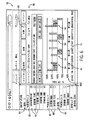
またさらに、本技法は、多岐にわたる基準で機器間の比較を可能にする。実際に、システムを比較することができ、比較結果の表現を、そのような比較の基礎をなすことができる任意の適切なパラメーターについて提供することができる。例示的な比較選択ページ142が図12に示されている。このページに示すように、ここでも複数のシステム80が、施設又はロケーション84に関してグループ82にグループ化されている。個々のシステム又はグループに対しステータスインジケーター86を提供することができる。このとき、図12に示すステータスページは、図13に示すように比較のためのシステムを選択する基礎としての役割を果たすことができる。ここでは、選択及び比較に同じシステム及びグループが利用可能である。比較ページ144はこれらのシステムを表示し、ユーザーが個々のシステム、グループ又は随意に作成される任意のサブグループをクリック又は選択することを可能にする。すなわち、システムのグループ全体を選択することができる一方、参照符号146によって示されるように、ユーザーは個々のシステム又は個々のグループを選択することができる。比較セクション148を設けることができ、この比較セクションでは、時間ごと、日ごと、週ごと、月ごと、又は任意の他の範囲等の比較のための時間基準を選択することができる。選択が行われると、次に、個々のシステムについて所望のパラメーターが比較される。ここで、システムは参照符号152に示されるように識別され、比較が行われ、この場合は参照符号154によって示されるようにグラフ表示される。示される例では、例えば、システムオン時間が比較のための基礎として選択された。システムのそれぞれのオン時間を反映する個々のシステムごとに、データが解析され、水平バーによってパーセンテージベースで提示されている。システム間で他の比較を直接行って、選択されたパラメーターを基礎として或るシステムが別のシステムより優れて機能したこと等を示すことができる。或る特定の実施形態では、2つ以上のパラメーターを選択することができ、これらは、未処理の値、処理済みの値又は計算された値に基づくことができる。
Still further, the present technique allows comparisons between instruments on a wide variety of criteria. Indeed, the systems can be compared and a representation of the comparison results can be provided for any suitable parameter that can form the basis for such comparison. An exemplary
本明細書において、本発明の或る特定の特徴だけが図示及び説明されてきたが、当業者には多くの変更及び変形が思い浮かぶであろう。それゆえ、添付の特許請求の範囲は、本発明の真の趣旨に入る全てのこのような変更及び変形を包含することを意図していることを理解されたい。 Although only certain specific features of the invention have been illustrated and described herein, many modifications and changes will occur to those skilled in the art. Therefore, it is to be understood that the appended claims are intended to cover all such modifications and variations as fall within the true spirit of this invention.
10 監視システム
12 溶接システム
14 溶接システム
16 支援機器
24 解析システム
26 オペレーターインターフェース
28 溶接機
30 リムーバブルメモリデバイス
32 解析システム
34 支援機器
36 サービスエンティティ
38 電力変換回路部
40 処理回路部
42 オペレーターインターフェース
46 リムーバブルメモリ
48 ワイヤ送給装置
50 スプール
52 駆動機構
54 駆動制御回路部
56 ガス弁
58 オペレーターインターフェース
62 帰線ケーブル(アースケーブルと呼ばれる場合もある)
64 溶接トーチ
68 データ収集コンポーネント
70 メモリ
72 報告コンポーネント
74 通信コンポーネント
78 目標レポートページ
80 システム
82 グループ
84 部門
86 ステータスインジケーター
88 目標タブ
94 提示
96 目標編集ページ
98 フィールド
104 ターゲット
106 シフトフィールド
108 目標設定ページ
110 システム識別情報
114 溶接トレースページ
116 システム
122 溶接トレースセクション
124 パラメーター
126 時間軸
128 トレース
132 履歴ページ
136 溶接
138 履歴トレースページ
142 比較選択ページ
144 比較ページ
148 比較セクション
DESCRIPTION OF
64
Claims (20)
ウェブベースシステムを介して、複数の金属製作リソースにおいて実行される金属製作動作のパラメーターを表すデータにアクセスすることと、
少なくとも1つのコンピュータープロセッサを介して、前記複数の金属製作リソースのそれぞれについて前記パラメーターを解析し、前記金属製作リソースのパフォーマンスを比較することと、
前記少なくとも1つのコンピュータープロセッサを介して、ユーザー閲覧可能レポートページを、前記解析を表す図形表示を用いて作成することと、
ウェブベースのシステムを介して、前記ユーザー閲覧可能レポートページをユーザーに送信することとを含む金属製作リソースのパフォーマンス比較方法。 A performance comparison method for metal production resources,
Accessing data representing parameters of metal fabrication operations performed on a plurality of metal fabrication resources via a web-based system;
Analyzing the parameters for each of the plurality of metal fabrication resources via at least one computer processor and comparing the performance of the metal fabrication resources;
Creating a user-viewable report page via the at least one computer processor using a graphical representation representing the analysis;
Sending the user-viewable report page to a user via a web-based system.
動作時に、複数の金属製作リソースの金属製作動作のパラメーターを表すデータにアクセスするウェブベースの通信コンポーネントと、
動作時に、前記パラメーターを解析して前記金属製作リソースのパフォーマンスを比較し、ユーザー閲覧可能レポートページを、前記金属製作リソースのそれぞれの前記解析を表す図形表示によって作成する、少なくとも1つのコンピュータープロセッサと、
動作時に、前記ユーザー閲覧可能レポートページをユーザーに移行する、ウェブベースの送信コンポーネントとを備える金属製作リソースのパフォーマンス比較システム。 A performance comparison system for metal production resources,
A web-based communication component that, in operation, accesses data representing parameters of metal fabrication operations of multiple metal fabrication resources;
At least one computer processor that, in operation, analyzes the parameters to compare the performance of the metal fabrication resource and creates a user-viewable report page with a graphical representation representing the analysis of each of the metal fabrication resources;
A metal fabrication resource performance comparison system comprising a web-based transmission component that, in operation, transitions the user-viewable report page to a user.
ウェブベースのシステムによって編集及び配信される少なくとも1つのユーザー閲覧可能レポートページであって、ユーザー閲覧デバイスに送信されるコンピューター実行コードによって定義され、該レポートページは、複数の金属製作リソースを特定するユーザー閲覧可能な表示と、関心対象の期間と、該関心対象の期間にわたって金属製作リソースにおいて行われる金属製作動作のパラメーターの少なくとも1つの図形表示とを含み、該図形表示は前記金属製作リソースのパフォーマンスを比較する、金属製作リソースのパフォーマンス比較インターフェース。 A performance comparison interface for metal production resources,
At least one user-viewable report page that is edited and distributed by a web-based system, defined by computer-executed code sent to a user-viewing device, the report page identifying a plurality of metal fabrication resources A viewable display, a period of interest, and at least one graphical display of parameters of a metal fabrication operation performed on the metal fabrication resource over the period of interest, wherein the graphical display is indicative of the performance of the metal fabrication resource. Compare metal production resource performance comparison interface.
Applications Claiming Priority (3)
| Application Number | Priority Date | Filing Date | Title |
|---|---|---|---|
| US13/838,541 US9665093B2 (en) | 2013-03-15 | 2013-03-15 | Welding resource performance comparison system and method |
| US13/838,541 | 2013-03-15 | ||
| PCT/US2014/017862 WO2014143532A1 (en) | 2013-03-15 | 2014-02-22 | Welding resource performance comparison system and method |
Publications (2)
| Publication Number | Publication Date |
|---|---|
| JP2016512171A true JP2016512171A (en) | 2016-04-25 |
| JP2016512171A5 JP2016512171A5 (en) | 2017-03-30 |
Family
ID=50349826
Family Applications (1)
| Application Number | Title | Priority Date | Filing Date |
|---|---|---|---|
| JP2016500346A Pending JP2016512171A (en) | 2013-03-15 | 2014-02-22 | Welding resource performance comparison system and method |
Country Status (10)
| Country | Link |
|---|---|
| US (3) | US9665093B2 (en) |
| EP (1) | EP2972618A1 (en) |
| JP (1) | JP2016512171A (en) |
| KR (1) | KR20150129655A (en) |
| AU (2) | AU2014228545A1 (en) |
| BR (1) | BR112015015882A2 (en) |
| CA (1) | CA2892520C (en) |
| DE (1) | DE202014011418U1 (en) |
| MX (1) | MX350860B (en) |
| WO (1) | WO2014143532A1 (en) |
Families Citing this family (13)
| Publication number | Priority date | Publication date | Assignee | Title |
|---|---|---|---|---|
| US9862051B2 (en) | 2011-09-27 | 2018-01-09 | Illinois Tool Works Inc. | Welding system and method utilizing cloud computing and data storage |
| US9665093B2 (en) * | 2013-03-15 | 2017-05-30 | Illinois Tool Works Inc. | Welding resource performance comparison system and method |
| US10558953B2 (en) | 2013-07-03 | 2020-02-11 | Illinois Tool Works Inc. | Welding system parameter comparison system and method |
| US9704140B2 (en) | 2013-07-03 | 2017-07-11 | Illinois Tool Works Inc. | Welding system parameter comparison system and method |
| US11103948B2 (en) | 2014-08-18 | 2021-08-31 | Illinois Tool Works Inc. | Systems and methods for a personally allocated interface for use in a welding system |
| US10242317B2 (en) | 2014-11-25 | 2019-03-26 | Illinois Tool Works Inc. | System for estimating the amount and content of fumes |
| US11022952B2 (en) | 2015-01-02 | 2021-06-01 | Illinois Tool Works Inc. | System and method for enhancing manufacturing efficiency via operator activity detection |
| US11131978B2 (en) | 2015-12-28 | 2021-09-28 | Illinois Tool Works Inc. | Systems and methods for analyzing manufacturing parameters |
| JP6409831B2 (en) * | 2016-08-08 | 2018-10-24 | 住友電気工業株式会社 | Management device and management program |
| US10896289B2 (en) * | 2017-10-18 | 2021-01-19 | Bently Nevada, Llc | Event list management system |
| US11267065B2 (en) * | 2019-02-18 | 2022-03-08 | Lincoln Global, Inc. | Systems and methods providing pattern recognition and data analysis in welding and cutting |
| US11768483B2 (en) | 2019-05-22 | 2023-09-26 | Illinois Tool Works Inc. | Distributed weld monitoring system with job tracking |
| US11400537B2 (en) | 2019-09-12 | 2022-08-02 | Illinois Tool Works Inc. | System and methods for labeling weld monitoring time periods using machine learning techniques |
Citations (2)
| Publication number | Priority date | Publication date | Assignee | Title |
|---|---|---|---|---|
| JPH1147950A (en) * | 1997-07-28 | 1999-02-23 | Miyachi Technos Corp | Remote welding control equipment |
| JP2004524611A (en) * | 2001-01-25 | 2004-08-12 | ザ リンカーン エレクトリック カンパニー | Systems and methods for providing a distributed welding architecture |
Family Cites Families (40)
| Publication number | Priority date | Publication date | Assignee | Title |
|---|---|---|---|---|
| US4825038A (en) | 1987-08-10 | 1989-04-25 | The United States Of America As Represented By The United States Department Of Energy | Method for controlling gas metal arc welding |
| KR100256665B1 (en) | 1997-10-07 | 2000-05-15 | 이종묵 | Spot welding monitoring system |
| AT501741B1 (en) | 1999-08-16 | 2006-11-15 | Fronius Int Gmbh | WELDING DEVICE WITH COMMUNICATION INTERFACE AND METHOD FOR OPERATING THE WELDING DEVICE |
| US20150121309A1 (en) | 2000-02-17 | 2015-04-30 | George Reed | Selection interface systems, structures, devices and methods |
| AT412076B (en) | 2000-12-15 | 2004-09-27 | Fronius Schweissmasch Prod | METHOD FOR CONNECTING SEVERAL WELDING DEVICES AND WELDING DEVICE THEREFOR |
| US6486439B1 (en) | 2001-01-25 | 2002-11-26 | Lincoln Global, Inc. | System and method providing automated welding information exchange and replacement part order generation |
| US6552303B1 (en) | 2001-05-29 | 2003-04-22 | Lincoln Global, Inc. | System for enabling arc welders |
| US6636776B1 (en) | 2001-07-09 | 2003-10-21 | Lincoln Global, Inc. | System and method for managing welding procedures and welding resources |
| US6639182B2 (en) | 2001-09-19 | 2003-10-28 | Illinois Tool Works Inc. | Pendant control for a welding-type system |
| JP2003211378A (en) | 2002-01-18 | 2003-07-29 | Yaskawa Electric Corp | Work information processor |
| WO2004004960A1 (en) | 2002-07-04 | 2004-01-15 | Fronius International Gmbh | Method for operating a welding device, and one such welding device |
| US6744011B1 (en) | 2002-11-26 | 2004-06-01 | General Motors Corporation | Online monitoring system and method for a short-circuiting gas metal arc welding process |
| US6940039B2 (en) | 2003-12-22 | 2005-09-06 | Lincoln Global, Inc. | Quality control module for tandem arc welding |
| US7908302B1 (en) | 2004-09-17 | 2011-03-15 | Symantec Operating Corporation | In-place splitting and merging of files |
| US7643890B1 (en) | 2005-01-13 | 2010-01-05 | Lincoln Global, Inc. | Remote management of portable construction devices |
| AT502326B1 (en) * | 2005-09-09 | 2009-07-15 | Fronius Int Gmbh | REMOTE ACCESS UNIT AND COMMUNICATION METHOD FOR MANAGING WELDING DEVICES |
| CN100451171C (en) | 2005-09-27 | 2009-01-14 | 北京东方新材科技有限公司 | Surface treatment for improving metal welding performance and work pieces therefrom |
| US8190282B2 (en) | 2006-06-09 | 2012-05-29 | Hitachi, Ltd. | Work management apparatus, picking carriage, work performance collection system, rework measurement system, workability management system, rework measurement measuring method, work performance collection method, workability management method and workability management program |
| US20080078811A1 (en) | 2006-09-15 | 2008-04-03 | The Lincoln Electric Company | Weld data acquisition |
| US9104195B2 (en) | 2006-12-20 | 2015-08-11 | Lincoln Global, Inc. | Welding job sequencer |
| EP1958738B1 (en) | 2007-02-13 | 2013-08-14 | Abb Research Ltd. | Remote diagnostic system for robots |
| GB2454232B (en) | 2007-11-01 | 2012-04-25 | Validation Ct Tvc Ltd | Welding support system |
| WO2009089337A1 (en) | 2008-01-09 | 2009-07-16 | Illinois Tool Works Inc. | Automatic weld arc monitoring system |
| JP5339096B2 (en) | 2008-02-22 | 2013-11-13 | 村田機械株式会社 | VAO Productivity Suite |
| US8847115B2 (en) | 2008-06-16 | 2014-09-30 | Illinois Tool Works Inc. | Configurable welding interface for automated welding applications |
| US20090327035A1 (en) | 2008-06-28 | 2009-12-31 | Microsoft Corporation | Media content service for renting jukeboxes and playlists adapted for personal media players |
| US8592722B2 (en) | 2008-11-03 | 2013-11-26 | Illinois Tool Works Inc. | Weld parameter interface |
| US8274013B2 (en) | 2009-03-09 | 2012-09-25 | Lincoln Global, Inc. | System for tracking and analyzing welding activity |
| US7970830B2 (en) | 2009-04-01 | 2011-06-28 | Honeywell International Inc. | Cloud computing for an industrial automation and manufacturing system |
| US20100299185A1 (en) | 2009-05-20 | 2010-11-25 | Caro Ricardo J | Diagnostic Tools and Methods Thereof |
| US8569646B2 (en) | 2009-11-13 | 2013-10-29 | Lincoln Global, Inc. | Systems, methods, and apparatuses for monitoring weld quality |
| US8706282B2 (en) | 2010-01-12 | 2014-04-22 | Ford Global Technologies, Llc | Weldability prediction and recommendation systems and methods |
| EP2585248B1 (en) | 2010-06-28 | 2017-10-18 | Precitec GmbH & Co. KG | Method for controlling a laser processing operation by means of a reinforcement learning agent and laser material processing head using the same |
| KR101186668B1 (en) | 2010-08-18 | 2012-09-27 | 고종철 | Remote monitoring system for welding |
| ES2767882T3 (en) | 2010-12-13 | 2020-06-18 | Lincoln Global Inc | Welding learning system |
| US9015173B2 (en) * | 2011-02-01 | 2015-04-21 | Honda Motor Co., Ltd. | Spot weld data management and monitoring system |
| US9053221B2 (en) | 2011-03-04 | 2015-06-09 | International Business Machines Corporation | Promotion of performance parameters in distributed data processing environment |
| US9862051B2 (en) | 2011-09-27 | 2018-01-09 | Illinois Tool Works Inc. | Welding system and method utilizing cloud computing and data storage |
| CN102922089B (en) | 2012-08-13 | 2014-10-29 | 天津大学 | Welding process information acquisition and quality monitoring device and method based on Ethernet |
| US9665093B2 (en) * | 2013-03-15 | 2017-05-30 | Illinois Tool Works Inc. | Welding resource performance comparison system and method |
-
2013
- 2013-03-15 US US13/838,541 patent/US9665093B2/en active Active
-
2014
- 2014-02-22 MX MX2015006640A patent/MX350860B/en active IP Right Grant
- 2014-02-22 AU AU2014228545A patent/AU2014228545A1/en not_active Abandoned
- 2014-02-22 WO PCT/US2014/017862 patent/WO2014143532A1/en active Application Filing
- 2014-02-22 EP EP14712373.1A patent/EP2972618A1/en not_active Ceased
- 2014-02-22 CA CA2892520A patent/CA2892520C/en active Active
- 2014-02-22 BR BR112015015882A patent/BR112015015882A2/en not_active IP Right Cessation
- 2014-02-22 JP JP2016500346A patent/JP2016512171A/en active Pending
- 2014-02-22 DE DE202014011418.8U patent/DE202014011418U1/en not_active Expired - Lifetime
- 2014-02-22 KR KR1020157017864A patent/KR20150129655A/en not_active IP Right Cessation
-
2016
- 2016-09-22 AU AU2016231591A patent/AU2016231591A1/en not_active Abandoned
-
2017
- 2017-05-16 US US15/596,393 patent/US10282693B2/en active Active
-
2019
- 2019-05-07 US US16/405,487 patent/US10885489B2/en active Active
Patent Citations (2)
| Publication number | Priority date | Publication date | Assignee | Title |
|---|---|---|---|---|
| JPH1147950A (en) * | 1997-07-28 | 1999-02-23 | Miyachi Technos Corp | Remote welding control equipment |
| JP2004524611A (en) * | 2001-01-25 | 2004-08-12 | ザ リンカーン エレクトリック カンパニー | Systems and methods for providing a distributed welding architecture |
Also Published As
| Publication number | Publication date |
|---|---|
| KR20150129655A (en) | 2015-11-20 |
| CA2892520C (en) | 2018-07-24 |
| CN105164596A (en) | 2015-12-16 |
| AU2016231591A1 (en) | 2016-10-13 |
| MX2015006640A (en) | 2015-11-16 |
| MX350860B (en) | 2017-09-19 |
| BR112015015882A2 (en) | 2017-07-11 |
| DE202014011418U1 (en) | 2020-04-28 |
| US20140278242A1 (en) | 2014-09-18 |
| US10885489B2 (en) | 2021-01-05 |
| AU2014228545A1 (en) | 2015-07-02 |
| US20190266543A1 (en) | 2019-08-29 |
| WO2014143532A1 (en) | 2014-09-18 |
| EP2972618A1 (en) | 2016-01-20 |
| US20170249578A1 (en) | 2017-08-31 |
| US9665093B2 (en) | 2017-05-30 |
| US10282693B2 (en) | 2019-05-07 |
| CA2892520A1 (en) | 2014-09-18 |
Similar Documents
| Publication | Publication Date | Title |
|---|---|---|
| US10885489B2 (en) | Welding resource performance comparison system and method | |
| US11288639B2 (en) | Welding system parameter comparison system and method | |
| KR102295274B1 (en) | Welding resource performance goal system and method | |
| JP2016516236A (en) | Welding resource tracking and analysis system and method | |
| JP2016525016A (en) | Welding system data management system and method |
Legal Events
| Date | Code | Title | Description |
|---|---|---|---|
| A521 | Request for written amendment filed |
Free format text: JAPANESE INTERMEDIATE CODE: A523 Effective date: 20170222 |
|
| A621 | Written request for application examination |
Free format text: JAPANESE INTERMEDIATE CODE: A621 Effective date: 20170222 |
|
| A977 | Report on retrieval |
Free format text: JAPANESE INTERMEDIATE CODE: A971007 Effective date: 20180125 |
|
| A131 | Notification of reasons for refusal |
Free format text: JAPANESE INTERMEDIATE CODE: A131 Effective date: 20180130 |
|
| A02 | Decision of refusal |
Free format text: JAPANESE INTERMEDIATE CODE: A02 Effective date: 20181113 |