KR20150125932A - Organic electroluminescence element - Google Patents
Organic electroluminescence element Download PDFInfo
- Publication number
- KR20150125932A KR20150125932A KR1020157022481A KR20157022481A KR20150125932A KR 20150125932 A KR20150125932 A KR 20150125932A KR 1020157022481 A KR1020157022481 A KR 1020157022481A KR 20157022481 A KR20157022481 A KR 20157022481A KR 20150125932 A KR20150125932 A KR 20150125932A
- Authority
- KR
- South Korea
- Prior art keywords
- group
- ring
- formula
- atom
- organic electroluminescent
- Prior art date
Links
Images


Classifications
-
- H—ELECTRICITY
- H10—SEMICONDUCTOR DEVICES; ELECTRIC SOLID-STATE DEVICES NOT OTHERWISE PROVIDED FOR
- H10K—ORGANIC ELECTRIC SOLID-STATE DEVICES
- H10K85/00—Organic materials used in the body or electrodes of devices covered by this subclass
- H10K85/10—Organic polymers or oligomers
- H10K85/111—Organic polymers or oligomers comprising aromatic, heteroaromatic, or aryl chains, e.g. polyaniline, polyphenylene or polyphenylene vinylene
- H10K85/115—Polyfluorene; Derivatives thereof
-
- H01L51/524—
-
- H—ELECTRICITY
- H10—SEMICONDUCTOR DEVICES; ELECTRIC SOLID-STATE DEVICES NOT OTHERWISE PROVIDED FOR
- H10K—ORGANIC ELECTRIC SOLID-STATE DEVICES
- H10K50/00—Organic light-emitting devices
- H10K50/80—Constructional details
- H10K50/84—Passivation; Containers; Encapsulations
- H10K50/842—Containers
- H10K50/8426—Peripheral sealing arrangements, e.g. adhesives, sealants
-
- H01L51/5237—
-
- H—ELECTRICITY
- H10—SEMICONDUCTOR DEVICES; ELECTRIC SOLID-STATE DEVICES NOT OTHERWISE PROVIDED FOR
- H10K—ORGANIC ELECTRIC SOLID-STATE DEVICES
- H10K50/00—Organic light-emitting devices
- H10K50/80—Constructional details
- H10K50/805—Electrodes
- H10K50/82—Cathodes
-
- H—ELECTRICITY
- H10—SEMICONDUCTOR DEVICES; ELECTRIC SOLID-STATE DEVICES NOT OTHERWISE PROVIDED FOR
- H10K—ORGANIC ELECTRIC SOLID-STATE DEVICES
- H10K50/00—Organic light-emitting devices
- H10K50/80—Constructional details
- H10K50/84—Passivation; Containers; Encapsulations
- H10K50/841—Self-supporting sealing arrangements
-
- H—ELECTRICITY
- H10—SEMICONDUCTOR DEVICES; ELECTRIC SOLID-STATE DEVICES NOT OTHERWISE PROVIDED FOR
- H10K—ORGANIC ELECTRIC SOLID-STATE DEVICES
- H10K77/00—Constructional details of devices covered by this subclass and not covered by groups H10K10/80, H10K30/80, H10K50/80 or H10K59/80
- H10K77/10—Substrates, e.g. flexible substrates
- H10K77/111—Flexible substrates
-
- H—ELECTRICITY
- H10—SEMICONDUCTOR DEVICES; ELECTRIC SOLID-STATE DEVICES NOT OTHERWISE PROVIDED FOR
- H10K—ORGANIC ELECTRIC SOLID-STATE DEVICES
- H10K85/00—Organic materials used in the body or electrodes of devices covered by this subclass
- H10K85/30—Coordination compounds
- H10K85/321—Metal complexes comprising a group IIIA element, e.g. Tris (8-hydroxyquinoline) gallium [Gaq3]
- H10K85/322—Metal complexes comprising a group IIIA element, e.g. Tris (8-hydroxyquinoline) gallium [Gaq3] comprising boron
-
- H—ELECTRICITY
- H01—ELECTRIC ELEMENTS
- H01L—SEMICONDUCTOR DEVICES NOT COVERED BY CLASS H10
- H01L2924/00—Indexing scheme for arrangements or methods for connecting or disconnecting semiconductor or solid-state bodies as covered by H01L24/00
- H01L2924/10—Details of semiconductor or other solid state devices to be connected
- H01L2924/11—Device type
- H01L2924/12—Passive devices, e.g. 2 terminal devices
- H01L2924/1204—Optical Diode
- H01L2924/12044—OLED
-
- H—ELECTRICITY
- H10—SEMICONDUCTOR DEVICES; ELECTRIC SOLID-STATE DEVICES NOT OTHERWISE PROVIDED FOR
- H10K—ORGANIC ELECTRIC SOLID-STATE DEVICES
- H10K2102/00—Constructional details relating to the organic devices covered by this subclass
-
- H—ELECTRICITY
- H10—SEMICONDUCTOR DEVICES; ELECTRIC SOLID-STATE DEVICES NOT OTHERWISE PROVIDED FOR
- H10K—ORGANIC ELECTRIC SOLID-STATE DEVICES
- H10K2102/00—Constructional details relating to the organic devices covered by this subclass
- H10K2102/301—Details of OLEDs
- H10K2102/311—Flexible OLED
-
- H—ELECTRICITY
- H10—SEMICONDUCTOR DEVICES; ELECTRIC SOLID-STATE DEVICES NOT OTHERWISE PROVIDED FOR
- H10K—ORGANIC ELECTRIC SOLID-STATE DEVICES
- H10K50/00—Organic light-emitting devices
- H10K50/10—OLEDs or polymer light-emitting diodes [PLED]
- H10K50/17—Carrier injection layers
-
- H—ELECTRICITY
- H10—SEMICONDUCTOR DEVICES; ELECTRIC SOLID-STATE DEVICES NOT OTHERWISE PROVIDED FOR
- H10K—ORGANIC ELECTRIC SOLID-STATE DEVICES
- H10K85/00—Organic materials used in the body or electrodes of devices covered by this subclass
- H10K85/10—Organic polymers or oligomers
-
- H—ELECTRICITY
- H10—SEMICONDUCTOR DEVICES; ELECTRIC SOLID-STATE DEVICES NOT OTHERWISE PROVIDED FOR
- H10K—ORGANIC ELECTRIC SOLID-STATE DEVICES
- H10K85/00—Organic materials used in the body or electrodes of devices covered by this subclass
- H10K85/10—Organic polymers or oligomers
- H10K85/141—Organic polymers or oligomers comprising aliphatic or olefinic chains, e.g. poly N-vinylcarbazol, PVC or PTFE
-
- H—ELECTRICITY
- H10—SEMICONDUCTOR DEVICES; ELECTRIC SOLID-STATE DEVICES NOT OTHERWISE PROVIDED FOR
- H10K—ORGANIC ELECTRIC SOLID-STATE DEVICES
- H10K85/00—Organic materials used in the body or electrodes of devices covered by this subclass
- H10K85/60—Organic compounds having low molecular weight
- H10K85/649—Aromatic compounds comprising a hetero atom
- H10K85/657—Polycyclic condensed heteroaromatic hydrocarbons
- H10K85/6572—Polycyclic condensed heteroaromatic hydrocarbons comprising only nitrogen in the heteroaromatic polycondensed ring system, e.g. phenanthroline or carbazole
-
- Y—GENERAL TAGGING OF NEW TECHNOLOGICAL DEVELOPMENTS; GENERAL TAGGING OF CROSS-SECTIONAL TECHNOLOGIES SPANNING OVER SEVERAL SECTIONS OF THE IPC; TECHNICAL SUBJECTS COVERED BY FORMER USPC CROSS-REFERENCE ART COLLECTIONS [XRACs] AND DIGESTS
- Y02—TECHNOLOGIES OR APPLICATIONS FOR MITIGATION OR ADAPTATION AGAINST CLIMATE CHANGE
- Y02E—REDUCTION OF GREENHOUSE GAS [GHG] EMISSIONS, RELATED TO ENERGY GENERATION, TRANSMISSION OR DISTRIBUTION
- Y02E10/00—Energy generation through renewable energy sources
- Y02E10/50—Photovoltaic [PV] energy
- Y02E10/549—Organic PV cells
Abstract
엄밀한 봉지 없이도 양호하게 구동하는 유기 전계 발광 소자를 제공하는 것을 목적으로 한다. 양극과, 기판 상에 형성된 음극 사이에 복수의 층이 적층된 구조를 갖는 유기 전계 발광 소자로서, 그 유기 전계 발광 소자는, 수증기 투과율이 10-6 ∼ 10-3 g/㎡·day 인 봉지가 된 것인 유기 전계 발광 소자이다.And an object of the present invention is to provide an organic electroluminescent device which can be driven well without strict sealing. An organic electroluminescent device having a structure in which a plurality of layers are laminated between an anode and a cathode formed on a substrate, wherein the organic electroluminescent device has a bag having a vapor transmissivity of 10 -6 to 10 -3 g / m 2 · day Organic electroluminescent device.
Description
본 발명은, 유기 전계 발광 소자에 관한 것이다. 보다 상세하게는, 전자 기기의 표시부 등의 표시 장치나 조명 장치 등으로서 이용 가능한 유기 전계 발광 소자에 관한 것이다.The present invention relates to an organic electroluminescent device. More particularly, the present invention relates to an organic electroluminescent device usable as a display device such as a display portion of an electronic device or a lighting device.
표시용 디바이스나 조명에 적용할 수 있는 새로운 발광 소자로서 유기 전계 발광 소자 (유기 EL 소자) 가 기대되고 있다.An organic electroluminescent device (organic EL device) is expected as a new light emitting device applicable to display devices and lighting.
유기 전계 발광 소자는, 양극과 음극 사이에 발광성 유기 화합물을 포함하여 형성되는 발광층을 포함하는 1 종 또는 복수종의 층을 끼운 구조를 갖고, 양극으로부터 주입된 홀과 음극으로부터 주입된 전자가 재결합할 때의 에너지를 이용하여 발광성 유기 화합물을 여기시켜, 발광을 얻는 것이다. 유기 전계 발광 소자는 전류 구동형의 소자이고, 흐르는 전류를 보다 효율적으로 활용하기 위해서, 소자 구조나, 소자를 구성하는 층의 재료에 대하여 다양하게 검토되고 있다.The organic electroluminescent device has a structure in which one or more kinds of layers including a light emitting layer formed by including a light emitting organic compound are sandwiched between an anode and a cathode, and holes injected from the anode and electrons injected from the cathode are recombined Energy is used to excite the luminescent organic compound to obtain luminescence. BACKGROUND ART An organic electroluminescent device is a current-driven type device. In order to utilize a flowing current more efficiently, various studies have been made on a device structure and a material of a layer constituting the device.
가장 기본적이고 많이 검토되고 있는 유기 전계 발광 소자의 구조는, 아다치 등에 의해 제안된 3 층 구조의 것으로 (비특허문헌 1 참조), 양극과 음극 사이에 정공 수송층, 발광층, 전자 수송층을 이 순서로 끼운 구조를 취하고 있다. 이 제안 이후, 유기 전계 발광 소자는 3 층 구조를 기본으로 하여, 보다 역할을 분담함으로써, 효율, 수명 등의 성능 향상을 목표로 하여 수많은 연구가 이루어지고 있다. 이 생각의 기본은, 주입되는 전자는 그 시점에서 (전극 중에 있어서) 높은 에너지를 가지고 있는 것이다.The structure of the organic electroluminescent device which is most basic and which has been extensively studied is a three-layer structure proposed by Adachi et al. (See Non-Patent Document 1), and a hole transport layer, a luminescent layer, and an electron transport layer are interposed between the anode and the cathode in this order Structure. After this proposal, the organic electroluminescent device has a three-layer structure as a base, and shares many of its roles, so that a lot of research has been conducted with the aim of improving performance such as efficiency and lifetime. The basis of this idea is that the injected electrons have a high energy (at the electrode) at that point.
그러므로, 유기 전계 발광 소자는 일반적으로 산소나 물에 의해 열화하기 쉬워, 이들의 침입을 방지하기 위해서 엄밀한 봉지가 불가결하였다. 열화의 원인으로는, 유기 화합물에 대한 전자 주입의 용이함으로부터, 음극으로서 사용할 수 있는 재료가 알칼리 금속이나 알칼리 금속 화합물 등, 일 함수가 작은 것에 한정되어 있는 것이나, 사용되는 유기 화합물 자체가 산소·물과 반응하기 쉬운 것을 들 수 있다. 엄밀한 봉지를 실시함으로써, 유기 전계 발광 소자는 다른 발광 소자와 비교하여 우위가 되었지만, 동시에 저가, 플렉시블과 같은 특장을 희생하게도 되었다.Therefore, the organic electroluminescent device is generally susceptible to deterioration by oxygen or water, and strict sealing is indispensable in order to prevent these intrusion. Examples of the cause of the deterioration include the fact that the material usable as the cathode is limited to those having a small work function such as an alkali metal or an alkali metal compound due to the ease of electron injection into the organic compound, And the like. By performing rigid sealing, the organic electroluminescent device became superior to other light emitting devices, but at the same time sacrificed features such as low cost and flexibility.
상기 서술한 바와 같이, 일반적으로 유기 전계 발광 소자는 엄밀한 봉지가 실시되고, 그에 따라 다른 발광 소자에 대한 우위성을 갖는 것이 된 한편, 저가, 플렉시블과 같은 특장을 희생해 왔다. 2013년, 급속한 플렉시블 디바이스의 진보, 그리고 관심의 확대에 수반하여, 현재, 플렉시블에 현실적으로 대응할 수 있는 유기 전계 발광 소자 기술이 급속히 요구되고 있다.As described above, in general, the organic electroluminescent device is strictly encapsulated and thus has superiority to other light emitting devices, while at the same time sacrificing features such as low cost and flexibility. With the rapid progress of flexible devices and the expansion of interest in 2013, an organic electroluminescent device technology capable of realistically responding flexibly is rapidly required.
본 발명은, 상기 현 상황을 감안하여 이루어진 것으로, 최대의 과제인 봉지에 관해서, 원리적인 관점에서 접근하여, 엄밀한 봉지 없이도 양호하게 구동하는 유기 전계 발광 소자를 제공하는 것을 목적으로 한다.An object of the present invention is to provide an organic electroluminescent device which is approached from the viewpoint of a principle regarding the encapsulation which is the greatest problem and which is driven well without strict sealing.
본 발명자는, 엄밀한 봉지 없이도 구동하는 유기 전계 발광 소자에 대하여 여러 가지 검토한 결과, 양극과, 기판 상에 형성된 음극 사이에 복수의 층이 적층된 역구조의 유기 전계 발광 소자에 주목하고, 역구조의 유기 전계 발광 소자가 구동하는 봉지의 조건에 대하여 검토한 결과, 종래의 엄밀한 봉지 (예를 들어, 유리) 인 수증기 투과율이 10-6 보다 봉지 성능이 높은 영역에 비하여 열등한 영역에서, 10-3 g/㎡·day 정도에 이를 때까지의 봉지 (이하에서는, 「수증기 투과율이 10-6 ∼ 10-3 g/㎡·day 인 봉지」 라고 적는다) 가 있으면, 소자로서 양호한 연속 구동 수명, 및, 보존 안정성이 얻어지는 것을 알아내고, 상기 과제를 훌륭하게 해결할 수 있는 것을 알아내고, 본 발명에 도달한 것이다.The inventors of the present invention have made various investigations on an organic electroluminescent device which is driven without strict sealing and as a result, attention is paid to an organic electroluminescent device having a reverse structure in which a plurality of layers are laminated between an anode and a cathode formed on a substrate, After a review with respect to the conditions of the bags to the organic electroluminescent device is driven, the conventional rigid bag in the inferior area compared to the high (e. g., glass) in water vapor permeability than the sealing performance in the regions 10-6, 10-3 (hereinafter referred to as " a bag having a water vapor permeability of 10 -6 to 10 -3 g / m 2 · day ") until reaching about 1 g / m 2 · day, The inventors have found out that the storage stability can be obtained, and that the above problems can be solved satisfactorily, and the present invention has been reached.
즉 본 발명은, 양극과, 기판 상에 형성된 음극 사이에 복수의 층이 적층된 구조를 갖는 유기 전계 발광 소자로서, 상기 유기 전계 발광 소자는, 수증기 투과율이 10-6 ∼ 10-3 g/㎡·day 인 봉지가 된 것인 유기 전계 발광 소자이다.That is, the present invention provides an organic electroluminescent device having a structure in which a plurality of layers are laminated between an anode and a cathode formed on a substrate, wherein the organic electroluminescent device has a vapor transmissivity of 10 -6 to 10 -3 g / Lt; RTI ID = 0.0 > day. ≪ / RTI >
이하에 본 발명을 상세히 서술한다.Hereinafter, the present invention will be described in detail.
또한, 이하에 있어서 기재하는 본 발명의 개개의 바람직한 형태를 2 개 이상 조합한 것도 또한, 본 발명의 바람직한 형태이다.It is also a preferable embodiment of the present invention that a combination of two or more of the respective preferred embodiments of the present invention described below.
본 발명의 유기 전계 발광 소자는, 수증기 투과율이 10-6 ∼ 10-3 g/㎡·day 인 봉지가 된 것이다.The organic electroluminescent device of the present invention is a sealed product having a water vapor permeability of 10 -6 to 10 -3 g / m 2 · day.
일반적으로 엄밀한 봉지가 불가결한 유기 전계 발광 소자의 경우, 수증기 투과율이 10-6 g/㎡·day 보다 낮은 수증기 투과율을 갖는 봉지가 필요하지만, 본 발명의 유기 전계 발광 소자는, 그 1000 배 정도의 수증기 투과율까지 허용하는 간이 봉지의 유기 전계 발광 소자이다.In general, in the case of an organic electroluminescent device in which strict sealing is indispensable, sealing with a water vapor transmission rate of less than 10 -6 g / m 2 · day is required. However, in the organic electroluminescent device of the present invention, It is a simple encapsulated organic electroluminescent device which permits water vapor permeability.
이와 같은 간이 봉지의 유기 전계 발광 소자의 최대의 장점은, 플렉시블화가 가능해지는 것, 저가로 제조할 수 있는 것이지만, 광 취출 효율을 높이는 필름 등의, 지금까지 그 봉지 성능으로부터 제한을 받고 있던 부재의 사용이 가능해지는 것도 큰 장점이다. 이로써, 저소비 전력, 장수명의 소자로 할 수 있다. 또한, 제품별 품질의 편차가 감소하고, 대면적화가 용이해지는 장점도 있다.The greatest merit of such a simple encapsulated organic electroluminescent device is that it can be made flexible and can be manufactured at a low cost. However, a film or the like for increasing the light extraction efficiency, It is also a great advantage to be able to use it. As a result, a device with low power consumption and long life can be obtained. In addition, there is also an advantage in that the variation in the quality of each product is reduced and the large area is facilitated.
본 발명의 유기 전계 발광 소자는, 양호한 발광 특성이 얻어지는 간이 봉지의 영역으로서, 수증기 투과율이 10-6 ∼ 10-3 g/㎡·day 인 봉지가 된 것이다. 양호한 발광 특성이란, 다크 스폿이 없는 것은 물론, 소자를 제작하여 500 시간 대기하에 둔 후의 소자의 기본 특성, 예를 들어, 전압-휘도 특성이 초기와 동등한 것을 의미하고, 보다 바람직하게는 소자를 제작하여 10000 시간 대기하에 둔 후의 소자의 전압-휘도 특성이 초기와 동등한 것을 의미한다. 수증기 투과율이 10-2 g/㎡·day 인 봉지가 되면, 본 발명에 있어서의 최적 조건하에서도 다크 스폿은 발생하지 않지만, 얼룩이 많이 발생하여, 휘도 저하가 현저해진다. 또한 수증기 투과율이 큰 숫자를 갖는 봉지가 되면, 연속적으로 발광 특성이 나빠져 가게 된다.The organic electroluminescent device of the present invention is a region of a simple encapsulation in which good luminescence characteristics can be obtained, and has a vapor permeability of 10 -6 to 10 -3 g / m 2 · day. Good light emission characteristics mean that basic characteristics, such as voltage-luminance characteristics, of the device after the device is manufactured and placed in the atmosphere for 500 hours, are equal to the initial value, and more preferably, And the voltage-luminance characteristic of the device after being left in the atmosphere for 10000 hours is equal to the initial value. When the bag has a water vapor transmission rate of 10 -2 g / m 2 · day, no dark spot is generated even under the optimum condition of the present invention, but a lot of unevenness occurs, and the luminance declines remarkably. Further, when the bag has a large number of water vapor transmittances, the light emission characteristics are deteriorated continuously.
유기 전계 발광 소자는, 제조 비용의 점에서는 엄밀한 봉지를 필요로 하지 않는 것이 바람직하고, 소자의 구동 수명의 점에서는 봉지가 보다 엄밀한 것이 바람직하지만, 이들 양방을 고려하면, 본 발명의 유기 전계 발광 소자는, 수증기 투과율이 10-6 ∼ 10-3 g/㎡·day 인 봉지가 되어 있는 것이 바람직하다. 보다 바람직하게는, 수증기 투과율이 10-5 ∼ 10-3 g/㎡·day 인 봉지가 되어 있는 것이다. 더욱 바람직하게는, 수증기 투과율이 10-5 ∼ 10-4 g/㎡·day 인 봉지가 되어 있는 것이다.It is preferable that the organic electroluminescent device does not require strict sealing in view of the manufacturing cost and it is preferable that the sealing is more strict in view of the driving lifetime of the device. Considering both of these, however, the organic electroluminescent device Is preferably a bag having a water vapor permeability of 10 -6 to 10 -3 g / m 2 · day. More preferably, the bag has a water vapor permeability of 10 -5 to 10 -3 g / m 2 · day. More preferably, the bag has a water vapor permeability of 10 -5 to 10 -4 g / m 2 · day.
유기 전계 발광 소자의 수증기 투과율은, 몇 가지 측정 장치가 고안되어 있고, 그 중 본 발명에서는 10-6 g/㎡·day 까지 측정할 필요가 있기 때문에 Ca 부식법에 의해 측정할 수 있다.Several measurement devices have been devised for the vapor transmissivity of the organic electroluminescent device, and in the present invention, it is necessary to measure the vapor transmissivity up to 10 -6 g / m 2 · day, so that the measurement can be made by the Ca corrosion method.
상기 수증기 투과율이 10-6 ∼ 10-3 g/㎡·day 인 봉지를 하는 방법은 특별히 제한되지 않고, 수증기 투과율이 10-6 ∼ 10-3 g/㎡·day 인 봉지 필름으로 유기 전계 발광 소자를 봉지하는 방법 등을 사용할 수 있다. 또한, 이와 같이 수증기 투과율을 10-6 ∼ 10-3 g/㎡·day 로 봉지하는 것 (수증기 투과율을 10-6 ∼ 10-3 g/㎡·day 로 봉지한 시스템) 및 이와 같은 수증기 투과율 10-6 ∼ 10-3 g/㎡·day 로 봉지하기 위해서 사용하는 부재도 또한, 본 발명의 하나이다. 이와 같은 수증기 투과율로 봉지하기 위한 부재로는, 봉지 필름이 바람직하다.The water vapor permeability is 10 -6 ~ 10 -3 g / ㎡ · How to the day of encapsulation is not particularly limited, the water vapor permeability of 10 -6 to 10 -3 g with an organic light emitting / ㎡ · day the sealant film element A method of encapsulating the material may be used. In addition, the water vapor transmission in this way 10 -6 ~ 10 -3 g / ㎡ · to a bag day (A bag system for the water vapor permeability by 10 -6 ~ 10 -3 g / ㎡ · day) , and this water vapor permeability: 10 -6 to 10 -3 g / m 2 · day is also one of the present invention. As the member for sealing with such a water vapor transmission rate, a sealing film is preferable.
봉지 필름으로 봉지된 유기 전계 발광 소자로 하는 경우, 봉지 필름 상에 봉지 필름과는 별로 기판을 설치하여, 그 기판 상에 음극을 형성하고, 음극 상에 각 층을 적층해도 되고, 봉지 필름을 기판으로서 이용하여, 봉지 필름 상에 직접 음극을 형성하고, 음극 상에 각 층을 적층해도 된다. 이들 어느 경우에 있어서도, 유기 전계 발광 소자는, 수증기 투과율이 10-6 ∼ 10-3 g/㎡·day 인 봉지 필름을 필수로 하는 박막 재료를 이용하여 형성되게 된다.In the case of an organic electroluminescent device sealed with a sealing film, a substrate may be provided on the sealing film different from the sealing film, a cathode may be formed on the substrate, each layer may be laminated on the cathode, , A negative electrode may be formed directly on the sealing film and each layer may be laminated on the negative electrode. In any of these cases, the organic electroluminescent device is formed using a thin film material that requires a sealing film having a water vapor transmission rate of 10 -6 to 10 -3 g / m 2 · day.
이와 같은, 본 발명의 유기 전계 발광 소자의 형성에 사용되는 박막 재료이고, 그 박막 재료는, 수증기 투과율이 10-6 ∼ 10-3 g/㎡·day 인 필름을 필수로 하는 유기 전계 발광 소자 형성용 박막 재료도 또한, 본 발명의 하나이다.The thin film material used for forming the organic electroluminescent device of the present invention is an organic electroluminescent device in which a film having a vapor transmissivity of 10 -6 to 10 -3 g / m 2 · day is essential Is also one of the present invention.
상기 유기 전계 발광 소자 형성용 박막 재료는, 수증기 투과율이 10-6 ∼ 10-3 g/㎡·day 인 필름만으로 이루어지는 것이어도 되고, 수증기 투과율이 10-6 ∼ 10-3 g/㎡·day 인 필름 상에, 1 개 또는 복수의 층이 적층된 것이어도 된다.The thin film material for forming an organic electroluminescent element may be composed of only a film having a water vapor transmission rate of 10 -6 to 10 -3 g / m 2 · day, or a film having a water vapor transmission rate of 10 -6 to 10 -3 g / m 2 · day One or a plurality of layers may be laminated on a film.
필름 상에, 1 개 또는 복수의 층이 적층된 것인 경우, 적층되는 층의 수나 종류는 특별히 제한되지 않지만, 바람직한 형태는, 필름과 필름 상에 형성된 기판으로 이루어지는 형태 ; 필름, 그리고, 필름 상에 순서대로 형성된 기판 및 음극으로 이루어지는 형태 ; 필름, 그리고, 필름 상에 순서대로 형성된 기판, 음극 및 전자 주입층으로 이루어지는 형태 ; 필름, 그리고, 필름 상에 순서대로 형성된 기판, 음극, 전자 주입층 및 버퍼층으로 이루어지는 형태 ; 필름, 그리고, 필름 상에 직접 형성된 음극으로 이루어지는 형태 ; 필름, 그리고, 필름 상에 직접 형성된 음극, 그 음극 상에 형성된 전자 주입층으로 이루어지는 형태 ; 필름, 그리고, 필름 상에 직접 형성된 음극, 그 음극 상에 형성된 전자 주입층, 그 전자 주입층 상에 형성된 버퍼층으로 이루어지는 형태 ; 를 들 수 있다.In the case where one or a plurality of layers are laminated on a film, the number and kinds of layers to be laminated are not particularly limited, but a preferred form is a form comprising a film and a substrate formed on the film; A film, and a form comprising a substrate and a cathode sequentially formed on a film; A film, and a substrate formed in this order on the film, a form comprising a cathode and an electron injection layer; A film, and a substrate formed in this order on the film, a cathode, an electron injection layer, and a buffer layer; Film, and a cathode formed directly on the film; A film, a form formed of a cathode directly formed on the film, and an electron injection layer formed on the cathode; A film, and a form formed of a cathode directly formed on the film, an electron injection layer formed on the cathode, and a buffer layer formed on the electron injection layer; .
기판, 음극, 전자 주입층, 버퍼층으로는, 후술하는 것이 바람직하다.The substrate, the cathode, the electron injection layer, and the buffer layer are preferably described later.
유기 전계 발광 소자를 구성하는 층에는, 발광층 외에, 전자 주입층, 전자 수송층, 정공 수송층, 정공 주입층 등이 있고, 이들 층이 적절히 선택되어 적층되어, 유기 전계 발광 소자가 구성된다.In the layer constituting the organic electroluminescent device, in addition to the light emitting layer, there are an electron injecting layer, an electron transporting layer, a hole transporting layer, and a hole injecting layer, and these layers are appropriately selected and laminated to constitute an organic electroluminescent device.
본 발명의 유기 전계 발광 소자는, 양극과, 기판 상에 형성된 음극 사이에 복수의 층이 적층된 구조를 갖는 것인 한, 적층되는 층의 구성은 특별히 제한되지 않지만, 음극, 전자 주입층, 필요에 따라 정공 저지층, 전자 수송층, 발광층, 필요에 따라 정공 수송층, 정공 주입층, 양극의 각 층이 이 순서로 인접하여 적층된 소자인 것이 바람직하다.The structure of the layer to be laminated is not particularly limited as long as the organic electroluminescent device of the present invention has a structure in which a plurality of layers are laminated between an anode and a cathode formed on a substrate, It is preferable that each layer of the hole blocking layer, the electron transporting layer, the light emitting layer, the hole transporting layer, the hole injecting layer, and the anode, if necessary, are stacked adjacently in this order.
본 발명의 유기 전계 발광 소자가 후술하는 버퍼층을 갖는 경우이고, 전자 수송층을 갖지 않는 경우, 또는, 버퍼층이 전자 수송층도 겸하는 경우에는 음극, 전자 주입층, 버퍼층, 정공 저지층, 발광층, 필요에 따라 정공 수송층, 정공 주입층, 양극의 각 층이 이 순서로 인접하여 적층된 소자인 것이 바람직하다.When the organic electroluminescent device of the present invention has a buffer layer to be described later and the electron transport layer is not provided, or when the buffer layer also serves as the electron transport layer, the cathode, the electron injection layer, the buffer layer, the hole blocking layer, It is preferable that each layer of the hole transport layer, the hole injection layer, and the anode are stacked adjacently in this order.
본 발명의 유기 전계 발광 소자가 후술하는 버퍼층을 갖고, 버퍼층과는 별도로 독립된 층으로서 전자 수송층을 갖는 경우에는, 본 발명의 유기 전계 발광 소자는, 음극, 전자 주입층, 버퍼층, 정공 저지층, 전자 수송층, 발광층, 필요에 따라 정공 수송층, 정공 주입층, 양극의 각 층이 이 순서로 인접하여 적층된 소자인 것이 바람직하다.In the case where the organic electroluminescent device of the present invention has a buffer layer to be described later and has an electron transporting layer as an independent layer separately from the buffer layer, the organic electroluminescent device of the present invention can be used as a cathode, an electron injection layer, a buffer layer, Transporting layer, a light-emitting layer, a hole-transporting layer, a hole-injecting layer, and an anode, if necessary, in this order.
또한, 이들 각 층은, 1 층으로 이루어지는 것이어도 되고, 2 층 이상으로 이루어지는 것이어도 된다.Each of these layers may be composed of one layer or two or more layers.
본 발명의 유기 전계 발광 소자에 있어서, 양극 및 음극으로는, 공지된 도전성 재료를 적절히 사용할 수 있지만, 광 취출을 위해서 적어도 어느 일방은 투명한 것이 바람직하다. 공지된 투명 도전성 재료의 예로는 ITO (주석 도프 산화인듐), ATO (안티몬 도프 산화인듐), IZO (인듐 도프 산화아연), AZO (알루미늄 도프 산화아연), FTO (불소 도프 산화인듐) 등을 들 수 있다. 불투명한 도전성 재료의 예로는, 칼슘, 마그네슘, 알루미늄, 주석, 인듐, 동, 은, 금, 백금이나 이들의 합금 등을 들 수 있다.In the organic electroluminescent device of the present invention, a well-known conductive material can be suitably used for the anode and the cathode, but at least one of them is preferably transparent for light extraction. Examples of the known transparent conductive material include ITO (tin doped indium oxide), ATO (antimony doped indium oxide), IZO (indium doped zinc oxide), AZO (aluminum doped zinc oxide), FTO (fluorine doped indium oxide) . Examples of the opaque conductive material include calcium, magnesium, aluminum, tin, indium, copper, silver, gold, platinum, and alloys thereof.
음극으로는, 이 중에서도, ITO, IZO, FTO 가 바람직하다.Among them, ITO, IZO and FTO are preferable as the cathode.
양극으로는, 이들 중에서도, Au, Ag, Al 이 바람직하다.Among these, Au, Ag, and Al are preferable as the anode.
상기와 같이, 일반적으로 양극에 사용되는 금속을 음극 및 양극에 사용할 수 있는 점에서, 상부 전극으로부터의 광의 취출을 상정하는 경우 (탑 에미션 구조의 경우) 에도 용이하게 실현할 수 있고, 상기 전극을 여러 종 선택하여 각각의 전극에 사용할 수 있다. 예를 들어, 하부 전극으로서 Al, 상부 전극에 ITO 등이다.As described above, since the metal used for the anode can be used for the cathode and the anode in general, it can be easily realized even in the case of taking out the light from the upper electrode (in the case of the top emission structure) Several species can be selected and used for each electrode. For example, Al as the lower electrode and ITO as the upper electrode.
상기 음극의 평균 두께는, 특별히 제한되지 않지만, 10 ∼ 500 ㎚ 인 것이 바람직하다. 보다 바람직하게는, 100 ∼ 200 ㎚ 이다. 음극의 평균 두께는, 촉침식 단차계, 분광 엘립소메트리에 의해 측정할 수 있다. 상기 양극의 평균 두께는, 특별히 한정되지 않지만, 10 ∼ 1000 ㎚ 인 것이 바람직하다. 보다 바람직하게는, 30 ∼ 150 ㎚ 이다. 또한, 불투과의 재료를 사용하는 경우에도, 예를 들어 평균 두께를 10 ∼ 30 ㎚ 정도로 함으로써, 탑 에미션형 및 투명형의 양극으로서 사용할 수 있다. 양극의 평균 두께는, 수정 진동자 막두께계에 의해 제막시에 측정할 수 있다.The average thickness of the negative electrode is not particularly limited, but is preferably 10 to 500 nm. More preferably, it is 100 to 200 nm. The average thickness of the cathode can be measured by a stylized step system, spectroscopic ellipsometry. The average thickness of the positive electrode is not particularly limited, but is preferably 10 to 1000 nm. More preferably, it is 30 to 150 nm. Even in the case of using an impermeable material, for example, by setting the average thickness to about 10 to 30 nm, it can be used as a top emission type and a transparent type anode. The average thickness of the positive electrode can be measured at the time of film formation by a quartz oscillator film thickness meter.
본 발명의 유기 전계 발광 소자는, 양극과 음극 사이에 금속 산화물층을 갖는 것이 바람직하다.The organic electroluminescent device of the present invention preferably has a metal oxide layer between the anode and the cathode.
양극과 음극 사이에 금속 산화물층을 갖는 것이면, 간이 봉지인 유기 전계 발광 소자가 보다 연속 구동 수명이나 보존 안정성이 우수한 것이 된다.If the metal oxide layer is provided between the anode and the cathode, the organic electroluminescent element as a simple bag has a better continuous driving life and storage stability.
보다 바람직하게는, 음극과 발광층 사이에 제 1 금속 산화물층을 갖고, 양극과 발광층 사이에 제 2 금속 산화물층을 갖는 것이다. 전술한 전자 주입층의 1 개는, 하기 제 1 금속 산화물층인 것이 바람직하다.More preferably, a first metal oxide layer is provided between the cathode and the light emitting layer, and a second metal oxide layer is provided between the anode and the light emitting layer. It is preferable that one of the above-described electron injection layers is a first metal oxide layer described below.
또한, 금속 산화물층의 중요성은, 제 1 금속 산화물층이 높고, 제 2 금속 산화물층은, 최저 비점유 분자 궤도가 극단적으로 깊은 유기 재료, 예를 들어, HATCN 으로도 치환할 수 있다.In addition, the importance of the metal oxide layer can be also replaced by an organic material having a high first metal oxide layer and a second metal oxide layer having an extremely low occupied molecular orbital, for example, HATCN.
제 1 금속 산화물층은, 단체의 금속 산화물막의 1 층으로 이루어지는 층, 혹은, 단체 또는 2 종류 이상의 금속 산화물을 적층 및/또는 혼합한 층인 반도체 혹은 절연체 적층 박막의 층이다. 금속 산화물을 구성하는 금속 원소로는, 마그네슘, 칼슘, 스트론튬, 바륨, 티탄, 지르코늄, 하프늄, 바나듐, 니오브, 탄탈, 크롬, 몰리브덴, 텅스텐, 망간, 인듐, 갈륨, 철, 코발트, 니켈, 동, 아연, 카드뮴, 알루미늄, 규소로 이루어지는 군에서 선택된다. 이들 중, 적층 또는 혼합 금속 산화물층을 구성하는 금속 원소의 적어도 1 개가, 마그네슘, 알루미늄, 칼슘, 지르코늄, 하프늄, 규소, 티탄, 아연으로 이루어지는 층인 것이 바람직하고, 그 중에서도 단체의 금속 산화물이면, 산화마그네슘, 산화알루미늄, 산화지르코늄, 산화하프늄, 산화규소, 산화티탄, 산화아연으로 이루어지는 군에서 선택되는 금속 산화물을 포함하는 것이 바람직하다.The first metal oxide layer is a layer of a single layer of a single metal oxide film or a layer of a semiconductor or insulator laminated thin film which is a layer formed by laminating and / or mixing two or more kinds of metal oxides. Examples of the metal element constituting the metal oxide include magnesium, calcium, strontium, barium, titanium, zirconium, hafnium, vanadium, niobium, tantalum, chromium, molybdenum, tungsten, manganese, indium, gallium, iron, cobalt, Zinc, cadmium, aluminum, and silicon. Of these, at least one of the metal elements constituting the laminated or mixed metal oxide layer is preferably a layer composed of magnesium, aluminum, calcium, zirconium, hafnium, silicon, titanium and zinc. And a metal oxide selected from the group consisting of magnesium, aluminum oxide, zirconium oxide, hafnium oxide, silicon oxide, titanium oxide, and zinc oxide.
상기 단체 또는 2 종류 이상의 금속 산화물을 적층 및/또는 혼합한 층의 예로는, 산화티탄/산화아연, 산화티탄/산화마그네슘, 산화티탄/산화지르코늄, 산화티탄/산화알루미늄, 산화티탄/산화하프늄, 산화티탄/산화규소, 산화아연/산화마그네슘, 산화아연/산화지르코늄, 산화아연/산화하프늄, 산화아연/산화규소, 산화칼슘/산화알루미늄 등의 금속 산화물의 조합을 적층 및/또는 혼합한 것이나, 산화티탄/산화아연/산화마그네슘, 산화티탄/산화아연/산화지르코늄, 산화티탄/산화아연/산화알루미늄, 산화티탄/산화아연/산화하프늄, 산화티탄/산화아연/산화규소, 산화인듐/산화갈륨/산화아연 등의 3 종의 금속 산화물의 조합을 적층 및/또는 혼합한 것 등을 들 수 있다. 이들 중에는, 특수한 조성으로서 양호한 특성을 나타내는 산화물 반도체인 IGZO 나 일렉트라이드인 12CaO7Al2O3 도 포함된다.Examples of the layer obtained by laminating and / or mixing two or more kinds of metal oxides include titanium oxide / zinc oxide, titanium oxide / magnesium oxide, titanium oxide / zirconium oxide, titanium oxide / aluminum oxide, titanium oxide / A combination of a metal oxide such as titanium oxide / silicon oxide, zinc oxide / magnesium oxide, zinc oxide / zirconium oxide, zinc oxide / hafnium oxide, zinc oxide / silicon oxide, calcium oxide / aluminum oxide, Titanium oxide / zinc oxide / magnesium oxide, titanium oxide / zinc oxide / zirconium oxide, titanium oxide / zinc oxide / aluminum oxide, titanium oxide / zinc oxide / hafnium oxide, titanium oxide / zinc oxide / silicon oxide, / Zinc oxide, and the like are laminated and / or mixed. Among these, it is also included in 12CaO7Al 2 O 3 as a special composition of IGZO oxide semiconductor showing good properties or Electra Id.
또한, 본 발명에 있어서는, 비저항이 10-4 Ω㎝ 보다 작은 것은 도전체, 비저항이 10-4 Ω㎝ 보다 큰 것은 반도체 또는 절연체로서 분류된다. 따라서, 투명 전극으로서 알려져 있는 ITO (주석 도프 산화인듐), ATO (안티몬 도프 산화인듐), IZO (인듐 도프 산화아연), AZO (알루미늄 도프 산화아연), FTO (불소 도프 산화인듐) 등의 박막은, 도전성이 높아 반도체 또는 절연체의 범주에 포함되지 않는 점에서 본 발명의 제 1 금속 산화물층을 구성하는 1 층에 해당하지 않는다.In the present invention, the specific resistance is smaller than 10 -4 is Ω㎝ conductors, the resistivity is greater than 10 -4 Ω㎝ is classified as a semiconductor or an insulator. Therefore, a thin film of ITO (tin doped indium oxide), ATO (antimony doped indium oxide), IZO (indium doped zinc oxide), AZO (aluminum doped zinc oxide), FTO (fluorine doped indium oxide) And does not correspond to one layer constituting the first metal oxide layer of the present invention in that it is high in conductivity and is not included in the category of semiconductor or insulator.
상기 제 2 금속 산화물층을 형성하는 금속 산화물로는, 특별히 제한되지 않지만, 산화바나듐 (V2O5), 산화몰리브덴 (MoO3), 산화텅스텐 (WO3), 산화루테늄 (RuO2) 등의 1 종 또는 2 종 이상을 사용할 수 있다. 이들 중에서도, 산화바나듐 또는 산화몰리브덴을 주성분으로 하는 것이 바람직하다. 제 2 금속 산화물층이 산화바나듐 또는 산화몰리브덴을 주성분으로 하는 것에 의해 구성되면, 제 2 금속 산화물층이 양극으로부터 정공을 주입하여 발광층 또는 정공 수송층으로 수송한다는 정공 주입층으로서의 기능이 보다 우수한 것이 된다. 또한, 산화바나듐 또는 산화몰리브덴은, 그 자체의 정공 수송성이 높기 때문에, 양극으로부터 발광층 또는 정공 수송층으로의 정공의 주입 효율이 저하하는 것을 바람직하게 방지할 수도 있다는 이점이 있다. 보다 바람직하게는, 산화바나듐 및/또는 산화몰리브덴으로 구성되는 것이다.A metal oxide to form the second metal oxide layer, particularly but not limited to, vanadium (V 2 O 5), molybdenum, such as (MoO 3), tungsten oxide (WO 3), ruthenium oxide (RuO 2) oxide One or more of them may be used. Among these, vanadium oxide or molybdenum oxide is preferably used as a main component. When the second metal oxide layer is constituted by vanadium oxide or molybdenum oxide as a main component, the second metal oxide layer has a better function as a hole injection layer for injecting holes from the anode into the light emitting layer or the hole transporting layer. Further, since vanadium oxide or molybdenum oxide has a high hole-transporting property, it has an advantage that the injection efficiency of holes from the anode to the light-emitting layer or the hole-transporting layer can be preferably prevented from being lowered. More preferably, it is composed of vanadium oxide and / or molybdenum oxide.
상기 제 1 금속 산화물층의 평균 두께는, 1 ㎚ 내지 수 ㎛ 정도까지 허용할 수 있지만, 저전압으로 구동할 수 있는 유기 전계 발광 소자로 하는 점에서, 1 ∼ 1000 ㎚ 인 것이 바람직하다. 보다 바람직하게는, 2 ∼ 100 ㎚ 이다.The average thickness of the first metal oxide layer can be from 1 nm to several micrometers, but it is preferably 1 to 1000 nm in view of an organic electroluminescent device that can be driven at a low voltage. More preferably, it is 2 to 100 nm.
상기 제 2 금속 산화물층의 평균 두께는, 특별히 한정되지 않지만, 1 ∼ 1000 ㎚ 인 것이 바람직하다. 보다 바람직하게는, 5 ∼ 50 ㎚ 이다.The average thickness of the second metal oxide layer is not particularly limited, but is preferably 1 to 1000 nm. More preferably, it is 5 to 50 nm.
제 1 금속 산화물층의 평균 두께는, 촉침식 단차계, 분광 엘립소메트리에 의해 측정할 수 있다.The average thickness of the first metal oxide layer can be measured by a touching step system, spectroscopic ellipsometry.
제 2 금속 산화물층의 평균 두께는, 수정 진동자 막두께계에 의해 제막시에 측정할 수 있다.The average thickness of the second metal oxide layer can be measured at the time of film formation by a quartz oscillator film thickness meter.
본 발명의 유기 전계 발광 소자는, 금속 산화물층과 발광층 사이에, 유기 화합물을 포함하는 재료에 의해 형성되는 버퍼층을 갖는 것이 바람직하다. 보다 바람직하게는, 유기 화합물을 포함하는 용액을 도포하여 형성되는 버퍼층을 갖는 것이다.The organic electroluminescent device of the present invention preferably has a buffer layer formed between a metal oxide layer and a light emitting layer by a material containing an organic compound. More preferably, the buffer layer is formed by applying a solution containing an organic compound.
역구조 유기 EL 에 있어서의 버퍼층의 역할은, (1) 전극으로부터 금속 산화물층에 의해 인상된 에너지 준위로부터 발광층 등의 유기 화합물층의 최저 비점유 분자 궤도의 에너지 준위까지 전자를 인상하는 것, (2) 활성의 금속 산화물층으로부터 주된 유기 EL 재료층을 보호하는 것 등을 들 수 있다. (1) 을 달성하는 수단으로서, 버퍼층을 환원제에 의해 도핑하는 것이나, 질소 원자 함유 치환기 등의 쌍극자를 갖는 부위를 포함하는 화합물에 의해 버퍼층을 형성하는 것을 생각할 수 있다. 환원제에 의해 도핑된 버퍼층을 갖는 것은 유기 전계 발광 소자의 바람직한 형태의 하나이지만, 본 발명의 유기 전계 발광 소자는, 간이의 봉지 소자이고, 그러한 봉지 환경하에서도 소자가 안정적으로 구동하기 위해서, 버퍼층에는 대기 안정성도 요구된다. 이 때문에, 환원제에 의해 도핑된 버퍼층을 사용하는 경우에는, 버퍼층을 박막화할 필요가 있다. 한편, 쌍극자를 갖는 부위를 포함하고, 캐리어 수송성을 갖는 화합물에 의해 버퍼층을 형성하는 경우에는, 박막화하는 것은 반드시 필요하지 않다.The role of the buffer layer in the inverse-structured organic EL is to raise electrons from the energy level pulled up by the metal oxide layer from the electrode to the energy level of the lowest unoccupied molecular orbital of the organic compound layer such as the light- ) Protecting the main organic EL material layer from the active metal oxide layer, and the like. (1), it is conceivable to form the buffer layer with a compound containing a site having a dipole such as a nitrogen atom-containing substituent or the like by doping the buffer layer with a reducing agent. The organic electroluminescent device of the present invention is a simple encapsulant, and in order to stably drive the device even under such encapsulant environment, the buffer layer is provided with a buffer layer doped with a reducing agent Atmospheric stability is also required. For this reason, when a buffer layer doped with a reducing agent is used, it is necessary to thin the buffer layer. On the other hand, in the case of forming a buffer layer by a compound having a carrier-transporting property including a site having a dipole, thinning is not necessarily required.
상기 (2) 에 대하여, 유기 전계 발광 소자의 금속 산화물층은, 후술하는 바와 같이 스프레이 열분해법, 졸 겔법, 스퍼터법 등의 방법으로 제막되고, 표면은 평활하지 않고 요철을 가진다. 이 금속 산화물층 상에, 진공 증착 등의 방법으로 발광층을 제막한 경우, 발광층의 원료가 되는 성분의 종류에 따라서는, 금속 산화물층의 표면의 요철이 결정 핵이 되어, 금속 산화물층에 접하는 발광층을 형성하는 재료의 결정화가 촉진된다. 이 때문에, 유기 전계 발광 소자를 완성시켰다고 해도, 큰 리크 전류가 흐르고, 발광면이 불균일화하여, 소자 성능이 저하하는 경향이 있다.With respect to the above (2), the metal oxide layer of the organic electroluminescence device is formed by a spray pyrolysis method, a sol-gel method, a sputtering method or the like as described later, and the surface is not smooth and has irregularities. When the light emitting layer is formed on the metal oxide layer by vacuum evaporation or the like, depending on the kind of the ingredient to be the raw material of the light emitting layer, the irregularities on the surface of the metal oxide layer become crystal nuclei, Is promoted. For this reason, even when the organic electroluminescent device is completed, a large leakage current flows, the light emitting surface becomes nonuniform, and the device performance tends to decrease.
그러나, 버퍼층을, 보다 바람직하게는, 용액을 도포하여 버퍼층을 형성하면, 표면이 평활한 층을 형성할 수 있기 때문에, 금속 산화물층과 발광층 사이에 도포에 의해 버퍼층을 형성하면, 발광층을 형성하는 재료의 결정화가 억제되고, 이에 의해, 금속 산화물층을 갖는 유기 전계 발광 소자가 발광층 등으로서 결정화가 일어나기 쉬운 재료를 사용한 경우에도, 리크 전류의 억제와 균일한 면 발광을 얻을 수 있게 된다.However, when a buffer layer is formed by applying a solution to form a buffer layer, a smooth surface layer can be formed. Therefore, when a buffer layer is formed between the metal oxide layer and the light emitting layer by coating, The crystallization of the material is suppressed. Thus, even when the organic electroluminescent element having the metal oxide layer is made of a material easily crystallized as the light emitting layer, the leakage current can be suppressed and the uniform surface light emission can be obtained.
상기 버퍼층은, 평균 두께가 5 ∼ 100 ㎚ 인 것이 바람직하다. 평균 두께가 이와 같은 범위임으로써, 발광층의 결정화를 억제하는 효과를 충분히 발휘할 수 있다. 버퍼층의 평균 두께가 5 ㎚ 보다 얇으면, 금속 산화물 표면에 존재하는 요철을 충분히 평활화할 수 없고, 리크 전류가 커져 버퍼층을 형성하는 것의 효과가 작아진다. 또한, 버퍼층의 평균 두께가 100 ㎚ 보다 두꺼우면, 구동 전압이 현저하게 상승하는 경향이 있다. 또한, 유기 화합물로서, 후술하는 본 발명에 있어서의 바람직한 구조의 화합물을 사용한 경우에는, 버퍼층은 전자 수송층으로서의 기능도 충분히 발휘할 수 있다. 상기 버퍼층의 평균 두께는, 보다 바람직하게는, 5 ∼ 60 ㎚ 이고, 더욱 바람직하게는, 10 ∼ 60 ㎚ 이다. 또한, 본 발명의 유기 전계 발광 소자의 연속 구동 수명의 점도 생각하면, 상기 버퍼층의 평균 두께는, 10 ∼ 30 ㎚ 인 것이 더욱 바람직하다.The buffer layer preferably has an average thickness of 5 to 100 nm. When the average thickness is in this range, the effect of suppressing the crystallization of the light emitting layer can be sufficiently exhibited. If the average thickness of the buffer layer is thinner than 5 nm, the unevenness existing on the surface of the metal oxide can not be sufficiently smoothed, and the leakage current becomes large, and the effect of forming the buffer layer becomes small. In addition, if the average thickness of the buffer layer is larger than 100 nm, the driving voltage tends to remarkably increase. In addition, when a compound having a preferable structure in the present invention is used as the organic compound described later, the buffer layer can sufficiently exhibit its function as an electron transporting layer. The average thickness of the buffer layer is more preferably 5 to 60 nm, and further preferably 10 to 60 nm. Further, considering the continuous driving lifetime of the organic electroluminescent device of the present invention, the average thickness of the buffer layer is more preferably 10 to 30 nm.
또한, 상기 서술한 바와 같이, 환원제에 의해 도핑된 버퍼층을 사용하는 경우에는, 버퍼층을 박막화하는 것이 소자의 대기 안정성의 관점에서 바람직하다. 이 경우, 버퍼층의 바람직한 평균 두께는, 버퍼층을 형성하는 유기 화합물을 포함하는 재료 중의 환원제의 양과도 관계하고, 그 재료가 유기 화합물에 대한 환원제의 함유량이 0.1 ∼ 15 질량% 인 경우, 버퍼층의 평균 두께가 5 ∼ 30 ㎚ 인 것이 바람직하다. 한편, 환원제의 도핑이 없는 경우, 혹은 극소량인 경우, 예를 들어, 그 재료가 유기 화합물에 대한 환원제의 함유량이 0 ∼ 0.1 질량% 인 경우에는, 막두께를 보다 두껍게 해도 대기 안정성이 양호하게 유지되는 경향이 있다. 예를 들어 그러한 경우에는, 버퍼층의 평균 두께가 5 ∼ 60 ㎚ 인 형태도 바람직하다. 소자 제작 상의 프로세스 안정성 및 소자 안정성으로부터는 후막인 것이 바람직하다.In addition, as described above, when a buffer layer doped with a reducing agent is used, it is preferable to make the buffer layer thin from the viewpoint of the atmospheric stability of the device. In this case, the preferable average thickness of the buffer layer is also related to the amount of the reducing agent in the material containing the organic compound forming the buffer layer, and when the material thereof is 0.1 to 15% by mass of the reducing agent relative to the organic compound, It is preferable that the thickness is 5 to 30 nm. On the other hand, in the case where the doping of the reducing agent is absent or in a very small amount, for example, when the content of the reducing agent for the organic compound is 0 to 0.1% by mass, the atmosphere stability is maintained . For example, in such a case, the buffer layer preferably has an average thickness of 5 to 60 nm. It is preferable that the film is a thick film from the viewpoints of process stability and device stability in device fabrication.
즉, (1) 유기 화합물을 포함하는 재료에 의해 형성되는 버퍼층을 갖고, 그 유기 화합물을 포함하는 재료는, 유기 화합물에 대한 환원제의 함유량이 0.1 ∼ 15 질량% 이고, 그 버퍼층의 평균 두께는, 5 ∼ 30 ㎚ 인 유기 전계 발광 소자나, (2) 유기 화합물을 포함하는 재료에 의해 형성되는 버퍼층을 갖고, 그 유기 화합물을 포함하는 재료는, 유기 화합물에 대한 환원제의 함유량이 0 ∼ 0.1 질량% 이고, 그 버퍼층의 평균 두께는, 5 ∼ 60 ㎚ 인 유기 전계 발광 소자도 또한, 본 발명의 바람직한 실시형태이다.(1) a buffer layer formed of a material containing an organic compound, wherein a content of the reducing agent relative to the organic compound is 0.1 to 15 mass%, and the average thickness of the buffer layer is (2) a buffer layer formed of a material containing an organic compound, wherein the content of the reducing agent relative to the organic compound is in the range of 0 to 0.1 mass% And the average thickness of the buffer layer is 5 to 60 nm is also a preferred embodiment of the present invention.
버퍼층의 평균 두께는 촉침식 단차계, 분광 엘립소메트리에 의해 측정할 수 있다.The average thickness of the buffer layer can be measured by a stylus step system, spectroscopic ellipsometry.
본 발명의 유기 전계 발광 소자에 있어서, 발광층을 형성하는 재료로는, 저분자 화합물이어도 되고 고분자 화합물이어도 되고, 이들을 혼합하여 사용해도 된다.In the organic electroluminescent device of the present invention, as a material for forming the light emitting layer, either a low molecular weight compound or a high molecular weight compound may be used.
또한, 본 발명에 있어서 저분자 재료란, 고분자 재료 (중합체) 가 아닌 재료를 의미하고, 분자량이 낮은 유기 화합물을 반드시 의미하는 것은 아니다.In the present invention, a low-molecular material means a material that is not a polymer material (polymer), and does not necessarily mean an organic compound having a low molecular weight.
상기 발광층을 형성하는 고분자 재료로는, 예를 들어, 트랜스형 폴리아세틸렌, 시스형 폴리아세틸렌, 폴리(디-페닐아세틸렌) (PDPA), 폴리(알킬, 페닐아세틸렌) (PAPA) 과 같은 폴리아세틸렌계 화합물 ; 폴리(파라-펜비닐렌) (PPV), 폴리(2,5-디알콕시-파라-페닐렌비닐렌) (RO-PPV), 시아노-치환-폴리(파라-펜비닐렌) (CN-PPV), 폴리(2-디메틸옥틸실릴-파라-페닐렌비닐렌) (DMOS-PPV), 폴리(2-메톡시, 5-(2'-에틸헥속시)-파라-페닐렌비닐렌) (MEH-PPV) 과 같은 폴리파라페닐렌비닐렌계 화합물 ; 폴리(3-알킬티오펜) (PAT), 폴리(옥시프로필렌)트리올 (POPT) 과 같은 폴리티오펜계 화합물 ; 폴리(9,9-디알킬플루오렌) (PDAF), 폴리(디옥틸플루오렌-알트-벤조티아디아졸) (F8BT), α,ω-비스[N,N'-디(메틸페닐)아미노페닐]-폴리[9,9-비스(2-에틸헥실)플루오렌-2,7-디일] (PF2/6am4), 폴리(9,9-디옥틸-2,7-디비닐렌플루오레닐-오르토-코(안트라센-9,10-디일) 과 같은 폴리플루오렌계 화합물 ; 폴리(파라-페닐렌) (PPP), 폴리(1,5-디알콕시-파라-페닐렌) (RO-PPP) 과 같은 폴리파라페닐렌계 화합물 ; 폴리(N-비닐카르바졸) (PVK) 과 같은 폴리카르바졸계 화합물 ; 폴리(메틸페닐실란) (PMPS), 폴리(나프틸페닐실란) (PNPS), 폴리(비페닐릴페닐실란) (PBPS) 과 같은 폴리실란계 화합물 ; 나아가 일본 특허출원 2010-230995호, 일본 특허출원 2011-6457호에 기재된 붕소 화합물계 고분자 재료 등을 들 수 있다.Examples of the polymer material forming the light emitting layer include polyacetylene-based materials such as trans-type polyacetylene, cis-type polyacetylene, poly (di-phenylacetylene) (PDPA), poly (alkylphenylacetylene) Compound; Poly (para-phenvylene) (PPV), poly (2,5-dialkoxy-para-phenylenevinylene) (RO-PPV), cyano- PPV), poly (2-dimethyloctylsilyl-para-phenylenevinylene) (DMOS-PPV), poly (2-methoxy, 5- MEH-PPV); Polythiophene-based compounds such as poly (3-alkylthiophene) (PAT) and poly (oxypropylene) triol (POPT); (PDAF), poly (dioctylfluorene-alt-benzothiadiazole) (F8BT), α, ω-bis [N, N'-di (methylphenyl) aminophenyl ] -Poly [9,9-bis (2-ethylhexyl) fluorene-2,7-diyl] (PF2 / 6am4), poly (9,9-dioctyl-2,7-divinylene fluorenyl- Poly (para-phenylene) (PPP), poly (1,5-dialkoxy-para-phenylene) (RO-PPP) (PMPS), poly (naphthylphenylsilane) (PNPS), poly (N-vinylcarbazole) (PVK) (PBPS), and boron compound-based polymer materials described in Japanese Patent Application No. 2010-230995 and Japanese Patent Application No. 2011-6457.
상기 발광층을 형성하는 저분자 재료로는, 후술하는 호스트로서 기능하는 금속 착물, 및, 인광 발광 재료 외에, 8-하이드록시퀴놀린 알루미늄 (Alq3), 트리스(4-메틸-8퀴놀리놀레이트) 알루미늄 (III) (Almq3), 8-하이드록시퀴놀린 아연 (Znq2), (1,10-페난트롤린)-트리스-(4,4,4-트리플루오로-1-(2-티에닐)-부탄-1,3-디오네이트)유로퓸 (III) (Eu(TTA)3(phen)), 2,3,7,8,12,13,17,18-옥타에틸-21H,23H-포르핀 플래티넘 (II) 과 같은 각종 금속 착물 ; 디스티릴벤젠 (DSB), 디아미노디스티릴벤젠 (DADSB) 과 같은 벤젠계 화합물, 나프탈렌, 나일 레드와 같은 나프탈렌계 화합물, 페난트렌과 같은 페난트렌계 화합물, 크리센, 6-니트로크리센과 같은 크리센계 화합물, 페릴렌, N,N'-비스(2,5-디-t-부틸페닐)-3,4,9,10-페릴렌-디-카르복시이미드 (BPPC) 와 같은 페릴렌계 화합물, 코로넨과 같은 코로넨계 화합물, 안트라센, 비스스티릴안트라센과 같은 안트라센계 화합물, 피렌과 같은 피렌계 화합물, 4-(디-시아노메틸렌)-2-메틸-6-(파라-디메틸아미노스티릴)-4H-피란 (DCM) 과 같은 피란계 화합물, 아크리딘과 같은 아크리딘계 화합물, 스틸벤과 같은 스틸벤계 화합물, 4,4'-비스[9-디카르바졸릴]-2,2'-비페닐 (CBP), 4,4'-비스(9-에틸-3-카르바조비닐렌)-1,1'-비페닐 (BCzVBi) 과 같은 카르바졸계 화합물, 2,5-디벤조옥사졸티오펜과 같은 티오펜계 화합물, 벤조옥사졸과 같은 벤조옥사졸계 화합물, 벤조이미다졸과 같은 벤조이미다졸계 화합물, 2,2'-(파라-페닐렌디비닐렌)-비스벤조티아졸과 같은 벤조티아졸계 화합물, 비스티릴(1,4-디페닐-1,3-부타디엔), 테트라페닐부타디엔과 같은 부타디엔계 화합물, 나프탈이미드와 같은 나프탈이미드계 화합물, 쿠마린과 같은 쿠마린계 화합물, 페리논과 같은 페리논계 화합물, 옥사디아졸과 같은 옥사디아졸계 화합물, 알다진계 화합물, 1,2,3,4,5-펜타페닐-1,3-시클로펜타디엔 (PPCP) 과 같은 시클로펜타디엔계 화합물, 퀴나크리돈, 퀴나크리돈 레드와 같은 퀴나크리돈계 화합물, 피롤로피리딘, 티아디아졸로피리딘과 같은 피리딘계 화합물, 2,2',7,7'-테트라페닐-9,9'-스피로비플루오렌과 같은 스피로 화합물, 프탈로시아닌 (H2Pc), 동프탈로시아닌과 같은 금속 또는 무금속의 프탈로시아닌계 화합물, 나아가 일본 공개특허공보 2009-155325호 및 일본 특허출원 2010-28273호에 기재된 붕소 화합물 재료 등을 들 수 있고, 이들의 1 종 또는 2 종 이상을 사용할 수 있다.Examples of the low-molecular material for forming the light-emitting layer include a metal complex which functions as a host to be described later, and a phosphorescent material such as 8-hydroxyquinoline aluminum (Alq 3 ), tris (4-methyl-8 quinolinolate) aluminum (III) (Almq 3), 8- hydroxyquinoline zinc (Znq 2), (1,10- phenanthroline) -tris- (4,4,4-trifluoro-1- (2-thienyl) -Butane-1,3-dionate) Europium (III) (Eu (TTA) 3 (phen)), 2,3,7,8,12,13,17,18-octaethyl- Various metal complexes such as platinum (II); Benzene-based compounds such as distyrylbenzene (DSB) and diaminodistyrylbenzene (DADSB), naphthalene-based compounds such as naphthalene and nile red, phenanthrene-based compounds such as phenanthrene, creases such as chrysene, A perylene compound such as perylene, N, N'-bis (2,5-di-t-butylphenyl) -3,4,9,10-perylene-di- carboxyimide (BPPC) (Di-cyanomethylene) -2-methyl-6- (para-dimethylaminostyryl) -2-methyl-6- Pyran compounds such as 4H-pyran (DCM), acridine compounds such as acridine, stilbene compounds such as stilbene, 4,4'-bis [9-dicarbazolyl] Carbazole-based compounds such as biphenyl (CBP), 4,4'-bis (9-ethyl-3-carbazovinylene) -1,1'-biphenyl (BCzVBi), 2,5- Tee with offen Benzoimidazole-based compounds such as benzoimidazole, benzothiazole-based compounds such as 2,2 '- (para-phenylenedivinylene) -bisbenzothiazole, benzothiazole-based compounds such as benzoimidazole, (1,4-diphenyl-1,3-butadiene), butadiene-based compounds such as tetraphenylbutadiene, naphthalimide-based compounds such as naphthalimide, coumarin-based compounds such as coumarin, Compounds, oxadiazole compounds such as oxadiazole, aldazine compounds, cyclopentadiene compounds such as 1,2,3,4,5-pentaphenyl-1,3-cyclopentadiene (PPCP), quinacridone compounds , Quinacridone-based compounds such as quinacridone red, pyridine-based compounds such as pyrrolopyridine and thiadiazolopyridine, 2,2 ', 7,7'-tetraphenyl-9,9'-spirobifluorene and the like A spiro compound, a phthalocyanine (H 2 Pc), a metal such as copper phthalocyanine Include a boron compound material described in Japanese Unexamined Patent Application Publication No. 2009-155325 and Japanese Patent Application No. 2010-28273, and the like, and one or more of these may be used.
본 발명의 유기 전계 발광 소자는, 발광층의 재료로서 상기 고분자 화합물이나 저분자 화합물도 사용할 수 있지만, 발광층에 호스트로서 기능하는 금속 착물을 1 종 포함하고, 거기에 게스트로서 저분자 화합물인 발광 재료가 분산된 것이 바람직하다. 이와 같은, 모두 저분자 화합물인 호스트-게스트를 조합한 발광층으로 함으로써, 유기 전계 발광 소자가 발광 효율이나 구동 수명 등의 발광 특성이 우수한 것이 된다. 그 이유는, 어떤 종의 금속 착물을 호스트 재료로 함으로써, 극단적으로 빠른 호스트-게스트 사이의 에너지 이동을 실현할 수 있고, 고에너지 환경하에 캐리어 (전자) 를 두는 시간을 보다 짧게 할 수 있기 때문이다. 그것을 위한, 호스트 재료에 요구되는 물성 요건은, 일중항 에너지 준위와 삼중항 에너지 준위의 에너지 갭을 최대한 제로에 가깝게 하는 것이다. 이로써, 빠른 에너지 이동을 실현할 수 있고, 보다 대기에 안정적이 된다. 구체적으로는 이하와 같다.In the organic electroluminescent device of the present invention, the above-mentioned polymer compound or a low-molecular compound can also be used as the material of the light-emitting layer, but it is also possible to use a single metal complex which functions as a host in the light- . By using such a light emitting layer in combination with a host-guest as a low-molecular compound, the organic electroluminescent device is excellent in light emission characteristics such as light emitting efficiency and driving lifetime. This is because, by using any kind of metal complex as a host material, it is possible to realize an energy transfer between extremely fast host-guest and to shorten the time to put a carrier (electron) under a high energy environment. For this purpose, the physical property required for the host material is to bring the energy gap of singlet energy level and triplet energy level as close to zero as possible. As a result, fast energy transfer can be realized and more stable in the atmosphere. Specifically, it is as follows.
발광층의 호스트는, 게스트와의 사이에서 에너지나 전자를 이동시켜 게스트를 여기 상태로 하는 역할을 갖고, 게스트와의 사이에서 에너지나 전자의 이동을 실시하는 호스트의 여기 에너지가 게스트의 여기 에너지보다 큰 것이 바람직하다. 발광층의 호스트로서 사용하는 금속 착물은, 전기 전도성을 갖고, 아모르퍼스 재료로서, 호스트로서 사용하는 발광 재료와의 사이에서 그와 같은 관계에 있는 것이면 사용할 수 있지만, 호스트로서 사용하는 금속 착물로는, 하기 식 (1) ; The host of the light-emitting layer has a role of moving energy or electrons between the host and the guest to make the guest into an excited state. When the excitation energy of the host that carries out energy or electron transfer with the guest is larger than the excitation energy of the guest . The metal complex used as the host of the light emitting layer can be used as long as it has electrical conductivity and is an amorphous material and has such a relationship with a light emitting material used as a host. (1);
[화학식 1][Chemical Formula 1]

(식 (1) 중, 점선의 원호는, 산소 원자와 질소 원자를 연결하는 골격 부분의 일부와 함께 고리 구조가 형성되어 있는 것을 나타내고, Z 와 질소 원자를 포함하여 형성되는 고리 구조는, 복소 고리 구조이다. X', X" 는, 동일 또는 상이하고, 수소 원자, 또는, 고리 구조의 치환기가 되는 1 가의 치환기를 나타내고, 점선의 원호 부분을 형성하는 고리 구조에 복수 개 결합하고 있어도 된다. X', X" 는, 결합하여 점선의 원호로 나타내는 2 개의 고리 구조의 일부와 함께 새로운 고리 구조를 형성해도 된다. 산소 원자와 질소 원자를 연결하는 골격 부분에 있어서의 점선은, 점선으로 연결되는 2 개의 원자가 단결합 또는 이중 결합으로 결합하고 있는 것을 나타낸다. M 은, 금속 원자를 나타낸다. Z 는, 탄소 원자 또는 질소 원자를 나타낸다. 질소 원자로부터 M 으로의 화살표는, 질소 원자가 M 원자에 배위하고 있는 것을 나타낸다. R0 은, 1 가의 치환기 또는 2 가의 연결기를 나타낸다. m 은 R0 의 수를 나타내고, 0 또는 1 의 수이다. n 은, 금속 원자 M 의 가수를 나타낸다. r 은, 1 또는 2 의 수이다.) 로 나타내는 금속 착물,(In the formula (1), the arc of the dotted line indicates that a ring structure is formed together with a part of the skeleton connecting the oxygen atom and the nitrogen atom, and the ring structure formed by including Z and the nitrogen atom is a heterocyclic ring X " and X "are the same or different and each represents a hydrogen atom or a monovalent substituent which is a substituent of a cyclic structure, and may be bonded to a ring structure forming an arcuate portion of a dotted line. ', And X''may combine to form a new ring structure together with a part of the two ring structures represented by the arc of the dotted line. The dotted line in the skeleton connecting the oxygen atom and the nitrogen atom is a M represents a metal atom, and Z represents a carbon atom or a nitrogen atom, and the nitrogen atom to M bond Table shows that they are coordinated to a nitrogen atom M atom. R 0 is, represents a monovalent substituent or a divalent connecting group. M represents the number of R 0, is a number of 0 or 1. N is a metal atom M And r is a number of 1 or 2,
하기 식 (2) ; (2);
[화학식 2](2)

(식 (2) 중, X', X" 는, 동일 또는 상이하고, 수소 원자, 또는, 퀴놀린 고리 구조의 치환기가 되는 1 가의 치환기를 나타내고, 퀴놀린 고리 구조에 복수 개 결합하고 있어도 된다. M 은, 금속 원자를 나타낸다. 질소 원자로부터 M 으로의 화살표는, 질소 원자가 M 원자에 배위하고 있는 것을 나타낸다. R0 은, 1 가의 치환기 또는 2 가의 연결기를 나타낸다. m 은 R0 의 수를 나타내고, 0 또는 1 의 수이다. n 은, 금속 원자 M 의 가수를 나타낸다. r 은, 1 또는 2 의 수이다.) 로 나타내는 금속 착물,(In the formula (2), X 'and X "are the same or different and each represents a hydrogen atom or a monovalent substituent which is a substituent of a quinoline ring structure, and may be bonded to a quinoline ring structure in plural. An atom from a nitrogen atom to M represents a nitrogen atom coordinated to the M atom, R 0 represents a monovalent substituent or a divalent linking group, m represents the number of R 0 , 0 Or a number of 1. n represents a valence of the metal atom M. r is a number of 1 or 2,
하기 식 (3) ;(3);
[화학식 3](3)

(식 (3) 중, 점선의 원호는, 산소 원자와 질소 원자를 연결하는 골격 부분의 일부와 함께 고리 구조가 형성되어 있는 것을 나타내고, Z 와 질소 원자를 포함하여 형성되는 고리 구조는, 복소 고리 구조이다. X', X" 는, 동일 또는 상이하고, 수소 원자, 또는, 고리 구조의 치환기가 되는 1 가의 치환기를 나타내고, 점선의 원호 부분을 형성하는 고리 구조에 복수 개 결합하고 있어도 된다. X', X" 는, 결합하여 점선의 원호로 나타내는 2 개의 고리 구조의 일부와 함께 새로운 고리 구조를 형성해도 된다. 산소 원자와 질소 원자를 연결하는 골격 부분에 있어서의 점선은, 점선으로 연결되는 2 개의 원자가 단결합 또는 이중 결합으로 결합하고 있는 것을 나타낸다. M 은, 금속 원자를 나타낸다. Z 는, 탄소 원자 또는 질소 원자를 나타낸다. 질소 원자로부터 M 으로의 화살표는, 질소 원자가 M 원자에 배위하고 있는 것을 나타낸다. n 은, 금속 원자 M 의 가수를 나타낸다. Xa 와 Xb 를 연결하는 실선의 원호는, Xa 와 Xb 가 적어도 1 개의 다른 원자를 개재하여 결합하고 있는 것을 나타내고, Xa 와 Xb 와 함께 고리 구조를 형성하고 있어도 된다. 또한 적어도 1 개의 다른 원자를 개재한 Xa 와 Xb 의 결합 중에 배위 결합을 포함하고 있어도 된다. Xa, Xb 는, 동일 또는 상이하고, 산소 원자, 질소 원자, 탄소 원자의 어느 것을 나타낸다. Xb 로부터 M 으로의 화살표는, Xb 가 M 원자에 배위하고 있는 것을 나타낸다. m' 는, 1 ∼ 3 의 수이다.) 으로 나타내는 금속 착물을 들 수 있고, 이들의 1 종 또는 2 종 이상을 사용할 수 있다.(In the formula (3), the arc of the dotted line indicates that a ring structure is formed together with a part of the skeleton connecting the oxygen atom and the nitrogen atom, and the ring structure formed by including Z and the nitrogen atom is a heterocyclic ring X " and X "are the same or different and each represents a hydrogen atom or a monovalent substituent which is a substituent of a cyclic structure, and may be bonded to a ring structure forming an arcuate portion of a dotted line. ', And X''may combine to form a new ring structure together with a part of the two ring structures represented by the arc of the dotted line. The dotted line in the skeleton connecting the oxygen atom and the nitrogen atom is a M represents a metal atom, and Z represents a carbon atom or a nitrogen atom, and the nitrogen atom to M bond Table shows that they are coordinated to a nitrogen atom M atom. N is indicates the valence of the metal atom M. X a and the arc of the solid line connecting the X b is, X a and X b is at least one other atom It indicates that the bond via, may form a ring structure together with X a and X b. in addition, it may contain a coordination bonds in the combination of at least one X a via the one other atom and X b. X a , X b is the same or different and represents any of an oxygen atom, a nitrogen atom and a carbon atom. An arrow from X b to M indicates that X b is coordinated to the M atom, m ' 3), and one or more of these may be used.
상기 식 (1) 에 있어서, r 이 1 인 경우, M 원자를 구조 중에 1 개 갖는 하기 식 (4-1) 로 나타내는 금속 착물이 되고, r 이 2 인 경우, M 원자를 구조 중에 2 개 갖는 하기 식 (4-2) 로 나타내는 금속 착물이 된다.In the above formula (1), when r is 1, the metal complex is represented by the following formula (4-1) having one M atom in its structure, and when r is 2, And becomes a metal complex represented by the following formula (4-2).
[화학식 4][Chemical Formula 4]

상기 식 (1), 식 (3) 에 있어서 점선의 원호로 나타내는 고리 구조로는, 1 개의 고리로 이루어지는 고리 구조여도 되고, 2 개 이상의 고리로 이루어지는 고리 구조여도 된다. 이와 같은 고리 구조로는, 탄소수 2 ∼ 20 의 방향 고리나 복소 고리를 들 수 있고, 벤젠 고리, 나프탈렌 고리, 안트라센 고리 등의 방향 고리 ; 디아졸 고리, 티아졸 고리, 이소티아졸 고리, 옥사졸 고리, 이소옥사졸 고리, 티아디아졸 고리, 옥사디아졸 고리, 트리아졸 고리, 이미다졸 고리, 이미다졸린 고리, 피리딘 고리, 피라진 고리, 피리다진 고리, 피리미딘 고리, 디아진 고리, 트리아진 고리, 벤조이미다졸 고리, 벤조티아졸 고리, 벤조옥사졸 고리, 벤조트리아졸 고리 등의 복소 고리를 들 수 있다.In the formulas (1) and (3), the ring structure represented by the dotted-line circular arc may be a ring structure composed of one ring or a ring structure composed of two or more rings. Examples of such a ring structure include an aromatic ring and a heterocyclic ring having 2 to 20 carbon atoms, and aromatic rings such as a benzene ring, a naphthalene ring, and an anthracene ring; A thiazole ring, an imidazole ring, an imidazoline ring, a pyridine ring, a pyrazine ring, a thiadiazole ring, an imidazole ring, an imidazole ring, an isothiazole ring, an oxazole ring, an isoxazole ring, a thiadiazole ring, , Heterocyclic rings such as pyridazine ring, pyrimidine ring, diazine ring, triazine ring, benzoimidazole ring, benzothiazole ring, benzoxazole ring and benzotriazole ring.
이들 중에서도, 벤젠 고리, 티아졸 고리, 이소티아졸 고리, 옥사졸 고리, 이소옥사졸 고리, 티아디아졸 고리, 옥사디아졸 고리, 트리아졸 고리, 이미다졸 고리, 이미다졸린 고리, 피리딘 고리, 피리다진 고리, 피리미딘 고리, 벤조이미다졸 고리, 벤조티아졸 고리, 벤조옥사졸 고리, 벤조트리아졸 고리가 바람직하다.Among them, preferred are benzene ring, thiazole ring, isothiazole ring, oxazole ring, isooxazole ring, thiadiazole ring, oxadiazole ring, triazole ring, imidazole ring, imidazoline ring, pyridine ring, A pyrimidine ring, a pyrimidine ring, a pyrimidine ring, a benzimidazole ring, a benzothiazole ring, a benzoxazole ring and a benzotriazole ring are preferable.
상기 식 (1) ∼ (3) 에 있어서 X', X" 로 나타내는 고리 구조가 갖는 치환기로는, 할로겐 원자, 탄소수 1 ∼ 20, 바람직하게는 탄소수 1 ∼ 10 의 알킬기, 탄소수 1 ∼ 20, 바람직하게는 탄소수 1 ∼ 10 의 아르알킬기, 탄소수 1 ∼ 20, 바람직하게는 탄소수 1 ∼ 10 의 알케닐기, 탄소수 1 ∼ 20, 바람직하게는 탄소수 1 ∼ 10 의 아릴기, 아릴아미노기, 시아노기, 아미노기, 아실기, 탄소수 1 ∼ 20, 바람직하게는 탄소수 1 ∼ 10 의 알콕시카르보닐기, 카르복실기, 탄소수 1 ∼ 20, 바람직하게는 탄소수 1 ∼ 10 의 알콕시기, 탄소수 1 ∼ 20, 바람직하게는 탄소수 1 ∼ 10 의 알킬아미노기, 탄소수 1 ∼ 20, 바람직하게는 탄소수 1 ∼ 10 의 디알킬아미노기, 탄소수 1 ∼ 20, 바람직하게는 탄소수 1 ∼ 10 의 아르알킬아미노기, 탄소수 1 ∼ 20, 바람직하게는 탄소수 1 ∼ 10 의 할로알킬기, 수산기, 아릴옥시기, 카르바졸기 등을 들 수 있다.Examples of the substituent in the ring structure represented by X 'and X "in the formulas (1) to (3) include a halogen atom, an alkyl group having 1 to 20 carbon atoms, preferably an alkyl group having 1 to 10 carbon atoms, An aralkyl group having 1 to 10 carbon atoms, an alkenyl group having 1 to 20 carbon atoms, preferably 1 to 10 carbon atoms, an aryl group having 1 to 20 carbon atoms, preferably 1 to 10 carbon atoms, an arylamino group, a cyano group, An alkoxycarbonyl group having 1 to 20 carbon atoms, preferably 1 to 10 carbon atoms, a carboxyl group, an alkoxy group having 1 to 20 carbon atoms, preferably 1 to 10 carbon atoms, an alkoxy group having 1 to 20 carbon atoms, preferably 1 to 10 carbon atoms An alkylamino group, a dialkylamino group having 1 to 20 carbon atoms, preferably 1 to 10 carbon atoms, an aralkylamino group having 1 to 20 carbon atoms, preferably 1 to 10 carbon atoms, an alkylamino group having 1 to 20 carbon atoms, preferably 1 to 10 carbon atoms Haloalkyl group, Group, and the like aryloxy group, a carbazole group.
또한, X', X" 로 나타내는 고리 구조가 갖는 치환기가 아릴기, 아릴아미노기인 경우, 아릴기, 아릴아미노기에 포함되는 방향 고리가 추가로 치환기를 가지고 있어도 되고, 그 경우의 치환기로는, 상기 X', X" 로 나타내는 치환기의 구체예와 동일한 것을 들 수 있다.When the substituent of the ring structure represented by X 'and X "is an aryl group or an arylamino group, the aromatic ring and the aromatic ring included in the arylamino group may further have a substituent. In this case, X ", and X ".
상기 식 (1), 식 (3) 으로 나타내는 점선의 원호로 나타내는 2 개의 고리 구조의 치환기가 결합하여 점선의 원호로 나타내는 2 개의 고리 구조의 일부와 함께 새로운 고리 구조를 형성하는 경우, 새롭게 형성되는 고리 구조로는, 5 원자 고리 구조나 6 원자 고리 구조를 들 수 있고, 점선의 원호로 나타내는 2 개의 고리 구조와 새로운 고리 구조를 합한 고리 구조로는, 예를 들어, 하기 (5-1), (5-2) 와 같은 구조를 들 수 있다.When the substituents of two ring structures represented by the arcs of the dotted line shown in the above-mentioned formulas (1) and (3) are bonded to form a new ring structure together with a part of the two ring structures represented by the dotted arc, Examples of the cyclic structure include a five-membered ring structure and a six-membered ring structure. As the ring structure combining two ring structures represented by a dotted-line circular arc and a new ring structure, for example, (5-2).
[화학식 5][Chemical Formula 5]

상기 식 (1) ∼ (3) 에 있어서, M 으로 나타내는 금속 원자로는, 주기표의 제 1 ∼ 3 족, 9 족, 10 족, 12 족 또는 13 족의 금속 원자가 바람직하고, 아연, 알루미늄, 갈륨, 백금, 로듐, 이리듐, 베릴륨, 마그네슘 중 어느 것이 바람직하다.In the above formulas (1) to (3), the metal atom represented by M is preferably a metal atom of
상기 식 (1), 식 (2) 에 있어서 R0 이 1 가의 치환기인 경우, 1 가의 치환기는, 하기 식 (6-1) ∼ (6-3) 의 어느 것이 바람직하다.In the above formulas (1) and (2), when R 0 is a monovalent substituent, the monovalent substituent is preferably any one of the following formulas (6-1) to (6-3).
[화학식 6][Chemical Formula 6]

(식 중, Ar1 ∼ Ar5 는, 치환기를 가지고 있어도 되는 방향 고리, 복소 고리, 혹은, 방향 고리 또는 복소 고리가 2 개 이상 직접 결합한 구조를 나타내고, Ar3 ∼ Ar5 는, 동일한 구조여도 되고 상이한 구조여도 된다. Q0 은, 규소 원자 또는 게르마늄 원자를 나타낸다.)(Wherein Ar 1 to Ar 5 represent a structure in which two or more aromatic rings, heterocyclic rings, aromatic rings, or heterocyclic rings which may have a substituent group are directly bonded, Ar 3 to Ar 5 may have the same structure And Q 0 represents a silicon atom or a germanium atom.)
Ar1 ∼ Ar5 의 방향 고리 또는 복소 고리의 구체예로는, 상기 식 (1) 에 있어서 점선의 원호로 나타내는 고리 구조의 방향 고리 또는 복소 고리의 구체예와 동일한 것을 들 수 있고, 방향 고리 또는 복소 고리가 2 개 이상 직접 결합한 구조로는, 이들 방향 고리 또는 복소 고리의 구체예로서 예시된 고리 구조가 2 개 이상 직접 결합한 구조를 들 수 있다. 또한 이 경우, 직접 결합하는 2 개 이상의 방향 고리나 복소 고리는 동일한 고리 구조여도 되고, 상이한 고리 구조여도 된다.Specific examples of the aromatic ring or heterocyclic ring of Ar 1 to Ar 5 include the same ones as those of the aromatic ring or heterocyclic ring of the ring structure represented by the arc of the dotted line in the above formula (1) As a structure in which two or more heterocyclic rings are directly bonded, there is a structure in which two or more ring structures exemplified as specific examples of these aromatic rings or heterocyclic rings are directly bonded. In this case, two or more aromatic rings or heterocyclic rings directly bonded may be the same ring structure or different ring structures.
방향 고리 또는 복소 고리의 치환기의 구체예로는, 상기 식 (1) 에 있어서 점선의 원호로 나타내는 고리 구조의 방향 고리 또는 복소 고리의 치환기의 구체예와 동일한 것을 들 수 있다.Specific examples of the substituent of the aromatic ring or heterocyclic ring may be the same as the specific examples of the aromatic ring or the heterocyclic substituent of the ring structure represented by the arc of the dotted line in the above formula (1).
또한,Also,
상기 식 (1), 식 (2) 에 있어서 R0 이 2 가의 연결기인 경우, R0 은 -O-, -CO- 의 어느 것이 바람직하다.In the above formulas (1) and (2), when R 0 is a divalent linking group, R 0 is preferably -O- or -CO-.
상기 식 (3) 에 있어서, Xa, Xb 와, Xa 와 Xb 를 연결하는 실선의 원호로 형성되는 구조는, 고리 구조를 1 개 또는 복수 포함하고 있어도 된다. 고리 구조는, Xa, Xb 를 포함하여 형성되어 있어도 되고, 그 경우의 고리 구조로는, 상기 식 (1), 식 (3) 에 있어서 점선의 원호로 나타내는 고리 구조와 동일한 것이나, 피라졸 고리를 들 수 있다. 바람직하게는, Xa, Xb 를 포함하여 피라졸 고리가 형성된 구조이다.In the formula (3), X a, the structure is formed in a circular arc of a solid line connecting the X and b, X a and X b are, or may, and a ring structure containing one or a plurality. The ring structure may be formed to include X a and X b . The ring structure in this case may be the same as the ring structure represented by the arc of the dotted line in the above formulas (1) and (3) The ring can be heard. Preferably, X a and X b are included to form a pyrazole ring.
상기 식 (3) 에 있어서, Xa 와 Xb 를 연결하는 실선의 원호는, 탄소 원자만으로 이루어지는 것이어도 되고, 다른 원자를 포함하고 있어도 된다. 다른 원자로는, 붕소 원자, 질소 원자, 황 원자 등을 들 수 있다.In the formula (3), the solid line arc connecting X a and X b may be composed of only carbon atoms or may contain other atoms. Other examples of the nuclear reactor include a boron atom, a nitrogen atom, and a sulfur atom.
또한 Xa 와 Xb 를 연결하는 실선의 원호는, Xa, Xb 를 포함하여 형성되는 고리 구조 이외의 고리 구조를 1 개 또는 2 개 이상 포함하고 있어도 되고, 그 경우의 고리 구조로는, 상기 식 (1), 식 (3) 에 있어서 점선의 원호로 나타내는 고리 구조와 동일한 것이나, 피라졸 고리를 들 수 있다.In addition, X a and the arc of the solid line connecting the X b is, and may contain a ring structure other than the ring structure formed including X a, X b 1 or 2 above, the ring structure of the case, In the above formulas (1) and (3), the same ring structure as the circular arc indicated by the dotted line, and the pyrazole ring may be mentioned.
상기 식 (3) 으로 나타내는 구조의 예로는, 하기 식 (7)의 구조 등을 들 수 있다.Examples of the structure represented by the formula (3) include a structure represented by the following formula (7).
[화학식 7](7)

(식 (7) 중, R1 ∼ R3 은, 동일 또는 상이하고, 수소 원자 또는 1 가의 치환기를 나타낸다. 질소 원자로부터 M 으로의 화살표 및 산소 원자로부터 M 으로의 화살표는, 질소 원자, 산소 원자가 M 원자에 배위하고 있는 것을 나타낸다. 점선의 원호, 산소 원자와 질소 원자를 연결하는 골격 부분에 있어서의 점선, X', X", M, Z, n, m' 는, 식 (3) 과 동일하다.)(In the formula (7), R 1 to R 3 are the same or different and represent a hydrogen atom or a monovalent substituent. Arrows from a nitrogen atom to M and arrows from an oxygen atom to M denote nitrogen atoms, oxygen atoms X ', X', M, Z, n and m 'in the skeleton connecting the oxygen atom and the nitrogen atom are the same as in the formula (3) Do.)
식 (7) 의 R1 ∼ R3 의 1 가의 치환기로는, 상기 식 (1) ∼ (3) 에 있어서 X', X" 로 나타내는 고리 구조가 갖는 치환기와 동일한 것을 들 수 있다.The monovalent substituents of R 1 to R 3 in the formula (7) include the same substituents as those of the ring structures represented by X 'and X "in the above formulas (1) to (3).
상기 식 (1) 로 나타내는 화합물의 구체예로는, 하기 식 (8-1) ∼ (8-40) 으로 나타내는 구조의 화합물 등을 들 수 있다.Specific examples of the compound represented by the formula (1) include compounds represented by the following formulas (8-1) to (8-40).
[화학식 8-1][Formula 8-1]

[화학식 8-2][Formula 8-2]

[화학식 8-3][Formula 8-3]

[화학식 8-4][Formula 8-4]

상기 식 (2) 로 나타내는 화합물의 구체예로는, 하기 식 (9-1) ∼ (9-3) 으로 나타내는 구조의 화합물 등을 들 수 있다.Specific examples of the compound represented by the formula (2) include compounds represented by the following formulas (9-1) to (9-3).
[화학식 9][Chemical Formula 9]

상기 식 (3) 으로 나타내는 화합물의 구체예로는, 하기 식 (10-1) ∼ (10-8) 로 나타내는 구조의 화합물 등을 들 수 있다.Specific examples of the compound represented by the formula (3) include compounds represented by the following formulas (10-1) to (10-8).
[화학식 10][Chemical formula 10]

본 발명에 있어서의 금속 착물로는, 상기 서술한 것의 1 종 또는 2 종 이상을 사용할 수 있지만, 이들 중에서도, 상기 식 (8-11) 로 나타내는 비스[2-(2-벤조티아졸릴)페놀라토]아연, 상기 식 (8-34) 로 나타내는 비스(10-하이드록시벤조[h]퀴놀리네이트)베릴륨 (Bebq2), 상기 식 (8-35) 로 나타내는 비스[2-(2-하이드록시페닐)-피리딘]베릴륨 (Bepp2) 이 바람직하다.As the metal complex in the present invention, one or more of the above-mentioned metal complexes can be used. Of these, bis [2- (2-benzothiazolyl) phenolato ] Bis (10-hydroxybenzo [h] quinolinate) beryllium (Bebq 2 ) represented by the above formula (8-34), bis [2- Phenyl) -pyridine] beryllium (Bepp 2 ) is preferred.
본 발명의 유기 전계 발광 소자의 발광층은, 인광 발광 재료를 포함하는 것이 바람직하다. 인광 발광 재료를 게스트로서 포함함으로써, 본 발명의 유기 전계 발광 소자가, 발광 효율 및 구동 수명이 보다 우수한 것이 된다.The light-emitting layer of the organic electroluminescent device of the present invention preferably includes a phosphorescent material. By including the phosphorescent material as a guest, the organic electroluminescent device of the present invention is more excellent in light emission efficiency and driving life.
인광 발광 재료로는, 하기 식 (11), (12) 의 어느 것으로 나타내는 화합물을 바람직하게 사용할 수 있다.As the phosphorescent material, compounds represented by any one of the following formulas (11) and (12) can be preferably used.
[화학식 11](11)

(식 (11) 중, 점선의 원호는, 산소 원자와 3 개의 탄소 원자로 구성된 골격 부분의 일부와 함께 고리 구조가 형성되어 있는 것을 나타내고, 질소 원자를 포함하여 형성되는 고리 구조는, 복소 고리 구조이다. X', X" 는, 동일 또는 상이하고, 수소 원자, 또는, 고리 구조의 치환기가 되는 1 가의 치환기를 나타내고, 점선의 원호 부분을 형성하는 고리 구조에 복수 개 결합하고 있어도 된다. X', X" 는, 결합하여 점선의 원호로 나타내는 2 개의 고리 구조의 일부와 함께 새로운 고리 구조를 형성해도 된다. 또한, n 이 2 이상인 경우에는, 복수의 X' 끼리 또는 X" 끼리가 결합하여 1 개의 치환기를 형성하고 있어도 된다. 질소 원자와 3 개의 탄소 원자로 구성된 골격 부분에 있어서의 점선은, 점선으로 연결되는 2 개의 원자가 단결합 또는 이중 결합으로 결합하고 있는 것을 나타낸다. M' 는, 금속 원자를 나타낸다. 질소 원자로부터 M' 로의 화살표는, 질소 원자가 M' 원자에 배위하고 있는 것을 나타낸다. n 은, 금속 원자 M' 의 가수를 나타낸다.)(In the formula (11), the arc of the dotted line indicates that a ring structure is formed together with a part of a skeleton portion composed of an oxygen atom and three carbon atoms, and the ring structure formed by including a nitrogen atom has a heterocyclic structure X 'and X "are the same or different and each represents a hydrogen atom or a monovalent substituent which is a substituent of a ring structure, and may be bonded to a ring structure forming an arcuate portion of a dotted line. X "may combine to form a new ring structure together with a part of two ring structures represented by a dotted arc. When n is 2 or more, a plurality of X 'or X" The dotted line in the skeleton portion constituted by the nitrogen atom and the three carbon atoms may be the same as in the case where two atoms connected by a dotted line are single bonds or double bonds And indicates that. M 'represents a metal atom. M from a nitrogen atom, an arrow is to the nitrogen atom represents a valence of M' indicates that they are coordinated to atoms. N is a metal atom M '.)
[화학식 12][Chemical Formula 12]

(식 (12) 중, 점선의 원호는, 산소 원자와 3 개의 탄소 원자로 구성된 골격 부분의 일부와 함께 고리 구조가 형성되어 있는 것을 나타내고, 질소 원자를 포함하여 형성되는 고리 구조는, 복소 고리 구조이다. X', X" 는, 동일 또는 상이하고, 수소 원자, 또는, 고리 구조의 치환기가 되는 1 가의 치환기를 나타내고, 점선의 원호 부분을 형성하는 고리 구조에 복수 개 결합하고 있어도 된다. X', X" 는, 결합하여 점선의 원호로 나타내는 2 개의 고리 구조의 일부와 함께 새로운 고리 구조를 형성해도 된다. 질소 원자와 3 개의 탄소 원자로 구성된 골격 부분에 있어서의 점선은, 점선으로 연결되는 2 개의 원자가 단결합 또는 이중 결합으로 결합하고 있는 것을 나타낸다. M' 는, 금속 원자를 나타낸다. 질소 원자로부터 M' 로의 화살표는, 질소 원자가 M' 원자에 배위하고 있는 것을 나타낸다. n 은, 금속 원자 M' 의 가수를 나타낸다. Xa 와 Xb 를 연결하는 실선의 원호는, Xa 와 Xb 가 적어도 1 개의 다른 원자를 개재하여 결합하고 있는 것을 나타내고, Xa 와 Xb 와 함께 고리 구조를 형성하고 있어도 된다. Xa, Xb 는, 동일 또는 상이하고, 산소 원자, 질소 원자, 탄소 원자의 어느 것을 나타낸다. Xb 로부터 M' 로의 화살표는, Xb 가 M' 원자에 배위하고 있는 것을 나타낸다. m' 는, 1 ∼ 3 의 수이다.)(In the formula (12), the arc of the dotted line indicates that a ring structure is formed together with a part of a skeleton portion composed of an oxygen atom and three carbon atoms, and the ring structure formed by including a nitrogen atom has a heterocyclic structure X 'and X "are the same or different and each represents a hydrogen atom or a monovalent substituent which is a substituent of a ring structure, and may be bonded to a ring structure forming an arcuate portion of a dotted line. X "may combine to form a new ring structure together with a part of the two ring structures represented by the arcs of the dotted line. The dotted line in the skeleton constituted by the nitrogen atom and the three carbon atoms is a straight- M 'represents a metal atom, and an arrow from a nitrogen atom to M' indicates that a nitrogen atom is coordinated to the M 'atom Indicates that. N is indicates the valence of the metal atom M '. X a and the arc of the solid line connecting the X b is, X a and X b represents that a is bonded together by the at least one other atom, X a and X b , X a and X b are the same or different and each represent an oxygen atom, a nitrogen atom, or a carbon atom. An arrow from X b to M 'indicates X b Is coordinated to the M 'atom, and m' is a number of 1 to 3.)
상기 식 (11) 및 식 (12) 에 있어서의 점선의 원호로 나타내는 고리 구조로는, 탄소수 2 ∼ 20 의 방향 고리나 복소 고리를 들 수 있고, 벤젠 고리, 나프탈렌 고리, 안트라센 고리 등의 방향족 탄화수소 고리 ; 피리딘 고리, 피리미딘 고리, 피라진 고리, 트리아진 고리, 벤조티아졸 고리, 벤조티올 고리, 벤조옥사졸 고리, 벤조옥솔 고리, 벤조이미다졸 고리, 퀴놀린 고리, 이소퀴놀린 고리, 퀴녹살린 고리, 및 페난트리딘 고리, 티오펜 고리, 푸란 고리, 벤조티오펜 고리, 벤조푸란 고리 등의 복소 고리를 들 수 있다.Examples of the ring structure represented by the dotted arc in the formulas (11) and (12) include an aromatic ring and a heterocyclic ring having 2 to 20 carbon atoms, and aromatic hydrocarbons such as a benzene ring, a naphthalene ring and an anthracene ring ring ; A pyrimidine ring, a pyrimidine ring, a pyrazine ring, a triazine ring, a benzothiazole ring, a benzothiol ring, a benzoxazole ring, a benzoxazole ring, a benzoimidazole ring, a quinoline ring, an isoquinoline ring, a quinoxaline ring, A thiophene ring, a furan ring, a benzothiophene ring, and a benzofuran ring.
상기 식 (11) 및 식 (12) 에 있어서 X', X" 로 나타내는 치환기로는, 상기 식 (1) 에 있어서 X', X" 로 나타내는 치환기와 동일한 것을 들 수 있다.Examples of the substituent represented by X 'and X "in the above formulas (11) and (12) include the same substituents as X' and X" in the above formula (1).
상기 식 (11) 및 식 (12) 에 있어서, 점선의 원호로 나타내는 2 개의 고리 구조가 갖는 치환기끼리가 결합하여 점선의 원호로 나타내는 2 개의 고리 구조의 일부와 함께 새로운 고리 구조를 형성하고 있는 경우, 점선의 원호로 나타내는 2 개의 고리 구조와 새로운 고리 구조를 합한 고리 구조로는, 예를 들어, 상기 (5-1), (5-2) 와 같은 구조를 들 수 있다.In the above formulas (11) and (12), when the substituents of the two ring structures represented by the arcs of the dotted line are bonded to each other to form a new ring structure together with a part of the two ring structures represented by the dotted arc (5-1) and (5-2) can be cited as the ring structure combining the two ring structures represented by the dotted line arcs and the new ring structure.
상기 식 (11) 및 식 (12) 에 있어서, M' 로 나타내는 금속 원자로는, 루테늄, 로듐, 팔라듐, 은, 레늄, 오스뮴, 이리듐, 백금 및 금을 들 수 있다.Examples of the metal atom represented by M 'in the formulas (11) and (12) include ruthenium, rhodium, palladium, silver, rhenium, osmium, iridium, platinum and gold.
상기 식 (12) 로 나타내는 구조로는, 하기 식 (13-1), (13-2) 의 구조 등을 들 수 있다.Examples of the structure represented by the formula (12) include the structures of the following formulas (13-1) and (13-2).
[화학식 13][Chemical Formula 13]

(식 (13-1), (13-2) 중, R1 ∼ R3 은, 동일 또는 상이하고, 수소 원자 또는 1 가의 치환기를 나타낸다. 식 (13-2) 에 있어서, R1 ∼ R3 이 1 가의 치환기인 경우, 고리 구조가 복수의 1 가의 치환기를 가지고 있어도 된다. 질소 원자로부터 M' 로의 화살표 및 산소 원자로부터 M' 로의 화살표는, 질소 원자, 산소 원자가 M' 원자에 배위하고 있는 것을 나타낸다. 점선의 원호, 질소 원자와 3 개의 탄소 원자로 구성된 골격 부분에 있어서의 점선, X', X", M', n, m' 는, 식 (12) 와 동일하다.)(13-1) and (13-2), R 1 to R 3 are the same or different and each represents a hydrogen atom or a monovalent substituent. In the formula (13-2), R 1 to R 3 The arrow from the nitrogen atom to M 'and the arrow from oxygen atom to M' indicate that the nitrogen atom and the oxygen atom are coordinated to the M 'atom X ', X', M ', n, and m' in the skeleton portion constituted by the atom of the dotted line, the nitrogen atom and the three carbon atoms are the same as in the formula (12).
R1 ∼ R3 의 1 가의 치환기로는, 상기 식 (1) ∼ (3) 에 있어서 X', X" 로 나타내는 고리 구조가 갖는 치환기와 동일한 것을 들 수 있다.Examples of the monovalent substituent of R 1 to R 3 include the same substituents as those of the ring structure represented by X 'and X "in the above formulas (1) to (3).
상기 식 (11) 이나 식 (12) 로 나타내는 화합물의 구체예로는, 하기 식 (14-1) ∼ (14-30) 으로 나타내는 화합물을 들 수 있다.Specific examples of the compound represented by the above formula (11) or (12) include compounds represented by the following formulas (14-1) to (14-30).
[화학식 14-1][Formula 14-1]

[화학식 14-2][Formula 14-2]

[화학식 14-3][Formula 14-3]

[화학식 14-4][Chemical Formula 14-4]

본 발명에 있어서의 인광 발광 재료로는, 상기 서술한 것의 1 종 또는 2 종 이상을 사용할 수 있지만, 이들 중에서도, 상기 식 (14-1) 로 나타내는 이리듐 트리스(2-페닐피리딘) (Ir(ppy)3), 상기 식 (14-19) 로 나타내는 이리듐 트리스(1-페닐이소퀴놀린) (Ir(piq)3), 상기 식 (14-27) 로 나타내는 이리듐 비스(2-메틸디벤조-[f,h]퀴녹살린)(아세틸아세토네이트) (Ir(MDQ)2(acac)), 상기 식 (14-28) 로 나타내는 이리듐 트리스[3-메틸-2-페닐피리딘] (Ir(mpy)3) 등이 바람직하다.Among them, iridium tris (2-phenylpyridine) (Ir (ppy (2-phenylpyridine)) represented by the formula (14-1) may be used as the phosphorescent material in the present invention. ) 3 ), iridium tris (1-phenylisoquinoline) (Ir (piq) 3 ) represented by the above formula (14-19), iridium bis (2-methyldibenzo [ , h] quinoxaline) (acetylacetonate) (Ir (MDQ) 2 (acac)), the formula (iridium tris [3-methyl-2-phenylpyridine] represented by the 14-28) (Ir (mpy) 3) .
상기 발광층에 있어서의 인광 발광 재료의 함유량은, 발광층을 형성하는 재료 100 질량% 에 대하여, 0.5 ∼ 20 질량% 인 것이 바람직하다. 이와 같은 함유량이면, 발광 특성을 보다 양호한 것으로 할 수 있다. 보다 바람직하게는, 0.5 ∼ 10 질량% 이고, 더욱 바람직하게는, 1 ∼ 6 질량% 이다.The content of the phosphorescent material in the light emitting layer is preferably 0.5 to 20% by mass with respect to 100% by mass of the material forming the light emitting layer. With such a content, the luminescence characteristics can be made better. More preferably, it is 0.5 to 10% by mass, and more preferably 1 to 6% by mass.
상기 발광층의 평균 두께는, 특별히 한정되지 않지만, 10 ∼ 150 ㎚ 인 것이 바람직하다. 보다 바람직하게는, 20 ∼ 100 ㎚ 이다.The average thickness of the light emitting layer is not particularly limited, but is preferably 10 to 150 nm. More preferably, it is 20 to 100 nm.
발광층의 평균 두께는, 저분자 화합물의 경우에는 수정 진동자 막두께계에 의해, 고분자 화합물의 경우에는 접촉식 단차계에 의해 측정할 수 있다.The average thickness of the light emitting layer can be measured by a quartz oscillator film thickness meter in the case of a low molecular compound, or by a contact step system in the case of a polymer compound.
상기 정공 수송층의 재료로는, 정공 수송층의 재료로서 통상적으로 사용할 수 있는 어느 화합물도 사용할 수 있고, 각종 p 형의 고분자 재료나, 각종 p 형의 저분자 재료를 단독 또는 조합하여 사용할 수 있다.As the material of the hole transporting layer, any compound which can be commonly used as a material of the hole transporting layer can be used, and various p-type polymer materials and various p-type low molecular materials can be used singly or in combination.
p 형의 고분자 재료 (유기 폴리머) 로는, 예를 들어, 폴리아릴아민, 플루오렌-아릴아민 공중합체, 플루오렌-비티오펜 공중합체, 폴리(N-비닐카르바졸), 폴리비닐피렌, 폴리비닐안트라센, 폴리티오펜, 폴리알킬티오펜, 폴리헥실티오펜, 폴리(p-페닐렌비닐렌), 폴리티닐렌비닐렌, 피렌포름알데하이드 수지, 에틸카르바졸포름알데하이드 수지 또는 그 유도체 등을 들 수 있다.Examples of the p-type polymer material (organic polymer) include polyarylamine, fluorene-arylamine copolymer, fluorene-bithiophene copolymer, poly (N-vinylcarbazole), polyvinylpyrene, polyvinyl There can be mentioned an anthracene, a polythiophene, a polyalkylthiophene, a polyhexylthiophene, a poly (p-phenylene vinylene), a polythynylene vinylene, a pyrene formaldehyde resin, an ethylcarbazole formaldehyde resin or a derivative thereof have.
또한 이들 화합물은, 다른 화합물과의 혼합물로서 사용할 수도 있다. 일례로서, 폴리티오펜을 함유하는 혼합물로는, 폴리(3,4-에틸렌디옥시티오펜/스티렌술폰산) (PEDOT/PSS) 등을 들 수 있다.These compounds may also be used as a mixture with other compounds. As an example, examples of the mixture containing polythiophene include poly (3,4-ethylenedioxythiophene / styrenesulfonic acid) (PEDOT / PSS).
상기 p 형의 저분자 재료로는, 1,1-비스(4-디-파라-트리아미노페닐)시클로헥산, 1,1'-비스(4-디-파라-톨릴아미노페닐)-4-페닐-시클로헥산과 같은 아릴시클로알칸계 화합물, 4,4',4"-트리메틸트리페닐아민, N,N,N',N'-테트라페닐-1,1'-비페닐-4,4'-디아민, N,N'-디페닐-N,N'-비스(3-메틸페닐)-1,1'-비페닐-4,4'-디아민 (TPD1), N,N'-디페닐-N,N'-비스(4-메톡시페닐)-1,1'-비페닐-4,4'-디아민 (TPD2), N,N,N',N'-테트라키스(4-메톡시페닐)-1,1'-비페닐-4,4'-디아민 (TPD3), N,N'-디(1-나프틸)-N,N'-디페닐-1,1'-비페닐-4,4'-디아민 (α-NPD), TPTE 와 같은 아릴아민계 화합물, N,N,N',N'-테트라페닐-파라-페닐렌디아민, N,N,N',N'-테트라(파라-톨릴)-파라-페닐렌디아민, N,N,N',N'-테트라(메타-톨릴)-메타-페닐렌디아민 (PDA) 과 같은 페닐렌디아민계 화합물, 카르바졸, N-이소프로필카르바졸, N-페닐카르바졸과 같은 카르바졸계 화합물, 스틸벤, 4-디-파라-톨릴아미노스틸벤과 같은 스틸벤계 화합물, OxZ 와 같은 옥사졸계 화합물, 트리페닐메탄, m-MTDATA 와 같은 트리페닐메탄계 화합물, 1-페닐-3-(파라-디메틸아미노페닐)피라졸린과 같은 피라졸린계 화합물, 벤진(시클로헥사디엔) 계 화합물, 트리아졸과 같은 트리아졸계 화합물, 이미다졸과 같은 이미다졸계 화합물, 1,3,4-옥사디아졸, 2,5-디(4-디메틸아미노페닐)-1,3,4-옥사디아졸과 같은 옥사디아졸계 화합물, 안트라센, 9-(4-디에틸아미노스티릴)안트라센과 같은 안트라센계 화합물, 플루오레논, 2,4,7-트리니트로-9-플루오레논, 2,7-비스(2-하이드록시-3-(2-클로로페닐카르바모일)-1-나프틸아조)플루오레논과 같은 플루오레논계 화합물, 폴리아닐린과 같은 아닐린계 화합물, 실란계 화합물, 1,4-디티오케토-3,6-디페닐-피롤로-(3,4-c)피롤로피롤과 같은 피롤계 화합물, 플루오렌과 같은 플루오렌계 화합물, 포르피린, 금속 테트라페닐포르피린과 같은 포르피린계 화합물, 퀴나크리돈과 같은 퀴나크리돈계 화합물, 프탈로시아닌, 동프탈로시아닌, 테트라(t-부틸)동프탈로시아닌, 철프탈로시아닌과 같은 금속 또는 무금속의 프탈로시아닌계 화합물, 동나프탈로시아닌, 바나딜나프탈로시아닌, 모노클로로갈륨나프탈로시아닌과 같은 금속 또는 무금속의 나프탈로시아닌계 화합물, N,N'-디(나프탈렌-1-일)-N,N'-디페닐-벤지딘, N,N,N',N'-테트라페닐벤지딘과 같은 벤지딘계 화합물 등을 들 수 있고, 이들의 1 종 또는 2 종 이상을 사용할 수 있다.Examples of the p-type low molecular weight material include 1,1-bis (4-di-para-trinaminophenyl) cyclohexane, 1,1'- Arylcycloalkane-based compounds such as cyclohexane, 4,4 ', 4 "-trimethyltriphenylamine, N, N, N', N'-tetraphenyl-1,1'-biphenyl- , N, N'-diphenyl-N, N'-bis (3-methylphenyl) -1,1'-biphenyl-4,4'- diamine (TPD1) (TPD2), N, N, N ', N'-tetrakis (4-methoxyphenyl) -1,1'-biphenyl-4,4'-diamine , 1'-biphenyl-4,4'-diamine (TPD3), N, N'-di (1-naphthyl) -N, N'- - diamine (? -NPD), arylamine compounds such as TPTE, N, N, N ', N'-tetraphenyl-para-phenylenediamine, N, N, N', N'- ) -Paraphenylene diamine, phenylenediamine compounds such as N, N, N ', N'-tetra (meta-tolyl) -metha-phenylenediamine (PDA), carbazole, N-isopropylcarbazole , N-phenylcarbazole Stilbene compounds such as stilbene and 4-di-para-tolylaminostilbene, oxazole compounds such as OxZ, triphenylmethane compounds such as triphenylmethane and m-MTDATA, 1-phenyl- (Para-dimethylaminophenyl) pyrazoline, triazine-based compounds such as benzene (cyclohexadiene) -based compounds, triazole, imidazole-based compounds such as imidazole, 1,3,4- Anthracene compounds such as anthracene, 9- (4-dimethylaminostyryl) anthracene, oxadiazole compounds such as 2,5-di (4-dimethylaminophenyl) -1,3,4-oxadiazole, (2-hydroxy-3- (2-chlorophenylcarbamoyl) -1-naphthylazo) fluorenone, such as 2,4,7-trinitro-9-fluorenone, 2,7- Aniline compounds such as polyaniline, silane compounds, 1,4-dithioceto-3,6-diphenyl-pyrrolo- (3,4-c) pyrrolopyrrole compounds, A fluorine-based compound such as fluorene, a porphyrin-based compound such as porphyrin, metal tetraphenylporphyrine, a quinacridone-based compound such as quinacridone, phthalocyanine, copper phthalocyanine, tetra (t- butyl) copper Metal or nonmetal phthalocyanine compounds such as phthalocyanine and iron phthalocyanine, metal or nonmetal naphthalocyanine compounds such as copper phthalocyanine, vanadyl phthalocyanine and monochlor gallium phthalocyanine, N, N'-di (naphthalene- Benzidine compounds such as N, N'-diphenyl-benzidine, N, N, N ', N'-tetraphenylbenzidine and the like can be used.
이들 중에서도, α-NPD, TPTE 와 같은 아릴아민계 화합물이 바람직하다.Of these, arylamine-based compounds such as? -NPD and TPTE are preferable.
본 발명의 유기 전계 발광 소자가 독립된 층으로서 정공 수송층을 갖는 경우, 정공 수송층의 평균 두께는, 특별히 한정되지 않지만, 10 ∼ 150 ㎚ 인 것이 바람직하다. 보다 바람직하게는, 40 ∼ 100 ㎚ 이다.When the organic electroluminescent device of the present invention has a hole transporting layer as an independent layer, the average thickness of the hole transporting layer is not particularly limited, but is preferably 10 to 150 nm. More preferably, it is 40 to 100 nm.
정공 수송층의 평균 두께는, 저분자 화합물의 경우에는 수정 진동자 막두께계에 의해, 고분자 화합물의 경우에는 접촉식 단차계에 의해 측정할 수 있다.The average thickness of the hole transporting layer can be measured by a quartz oscillator film thickness meter in the case of a low molecular compound, or by a contact type step system in the case of a high molecular compound.
상기 전자 수송층의 재료로는, 전자 수송층의 재료로서 통상적으로 사용할 수 있는 어느 화합물도 사용할 수 있고, 이들을 혼합하여 사용해도 된다.As the material of the electron transporting layer, any compound which can be commonly used as a material for the electron transporting layer may be used, or a mixture thereof may be used.
전자 수송층의 재료로서 사용할 수 있는 저분자 화합물의 예로는, 후술하는 식 (15) 로 나타내는 붕소 함유 화합물 외에, 트리스-1,3,5-(3'-(피리딘-3"-일)페닐)벤젠 (TmPyPhB) 과 같은 피리딘 유도체, (2-(3-(9-카르바졸릴)페닐)퀴놀린 (mCQ)) 과 같은 퀴놀린 유도체, 2-페닐-4,6-비스(3,5-디피리딜페닐)피리미딘 (BPyPPM) 과 같은 피리미딘 유도체, 피라진 유도체, 바소페난트롤린 (BPhen) 과 같은 페난트롤린 유도체, 2,4-비스(4-비페닐)-6-(4'-(2-피리디닐)-4-비페닐)-[1,3,5]트리아진 (MPT) 과 같은 트리아진 유도체, 3-페닐-4-(1'-나프틸)-5-페닐-1,2,4-트리아졸 (TAZ) 과 같은 트리아졸 유도체, 옥사졸 유도체, 2-(4-비페닐릴)-5-(4-tert-부틸페닐-1,3,4-옥사디아졸) (PBD) 과 같은 옥사디아졸 유도체, 2,2',2"-(1,3,5-벤트리일)-트리스(1-페닐-1-H-벤즈이미다졸) (TPBI) 과 같은 이미다졸 유도체, 나프탈렌, 페릴렌 등의 방향 고리 테트라카르복실산 무수물, 비스[2-(2-하이드록시페닐)벤조티아졸라토]아연 (Zn(BTZ)2), 트리스(8-하이드록시퀴놀리나토)알루미늄 (Alq3) 등으로 대표되는 각종 금속 착물, 2,5-비스(6'-(2',2"-비피리딜))-1,1-디메틸-3,4-디페닐실롤 (PyPySPyPy) 등의 실롤 유도체로 대표되는 유기 실란 유도체 등을 들 수 있고, 이들의 1 종 또는 2 종 이상을 사용할 수 있다.Examples of the low-molecular compound that can be used as the material of the electron transport layer include boron-containing compounds represented by the following formula (15), tris-1,3,5- (3 ' (TmPyPhB), quinoline derivatives such as (2- (3- (9- carbazolyl) phenyl) quinoline (mCQ)), 2-phenyl-4,6-bis (4-biphenyl) -6- (4 ' - (2 (phenyl) 3-phenyl-4- (1'-naphthyl) -5-phenyl-1,2,4,5,6-tetrahydronaphthalene (MPT) , 4-triazole (TAZ), oxazole derivatives, 2- (4-biphenylyl) -5- (4-tert- butylphenyl-1,3,4-oxadiazole) Imidazole derivatives such as 2,2 ', 2 "- (1,3,5-benzyl) -tris (1-phenyl-1-H-benzimidazole) (TPBI) Naphthalene, (2-hydroxyphenyl) benzothiazolato] zinc (Zn (BTZ) 2 ), tris (8-hydroxyquinolinato) aluminum (Alq3), tetracarboxylic acid anhydride , And silanol derivatives such as 2,5-bis (6 '- (2', 2 "-bipyridyl)) -1,1-dimethyl-3,4-diphenylsilole (PyPySPyPy) , And the like. One or more of these may be used.
이들 중에서도, Alq3 과 같은 금속 착물, TmPyPhB 와 같은 피리딘 유도체가 바람직하다.Among these, metal complexes such as Alq 3 and pyridine derivatives such as TmPyPhB are preferable.
본 발명의 유기 전계 발광 소자가 독립된 층으로서 전자 수송층을 갖는 경우, 전자 수송층의 평균 두께는, 특별히 한정되지 않지만, 10 ∼ 150 ㎚ 인 것이 바람직하다. 보다 바람직하게는, 40 ∼ 100 ㎚ 이다.When the organic electroluminescent device of the present invention has an electron transporting layer as an independent layer, the average thickness of the electron transporting layer is not particularly limited, but is preferably 10 to 150 nm. More preferably, it is 40 to 100 nm.
전자 수송층의 평균 두께는, 저분자 화합물의 경우에는 수정 진동자 막두께계에 의해, 고분자 화합물의 경우에는 접촉식 단차계에 의해 측정할 수 있다.The average thickness of the electron transporting layer can be measured by a quartz oscillator film thickness meter in the case of a low molecular compound, or by a contact type step system in the case of a polymer compound.
본 발명의 유기 전계 발광 소자에 있어서, 금속 산화물층, 음극, 양극, 발광층, 정공 수송층, 전자 수송층을 형성하는 방법은 특별히 제한되지 않고, 기상 제막법인 플라즈마 CVD, 열 CVD, 레이저 CVD 등의 화학 증착법 (CVD), 진공 증착, 스퍼터링, 이온 플레이팅 등의 건식 도금법, 용사법, 그리고 액상 제막법인 전해 도금, 침지 도금, 무전해 도금 등의 습식 도금법, 졸·겔법, MOD 법, 스프레이 열분해법, 미립자 분산액을 사용한 닥터 블레이드법, 스핀 코트법, 잉크젯법, 스크린 프린팅법 등의 인쇄 기술 등을 사용할 수 있고, 재료에 따른 적절한 방법을 선택하여 사용할 수 있다.The method for forming the metal oxide layer, the cathode, the anode, the light emitting layer, the hole transporting layer, and the electron transporting layer in the organic electroluminescent device of the present invention is not particularly limited and may be a chemical vapor deposition method such as plasma CVD, thermal CVD, A dry plating method such as chemical vapor deposition (CVD), vacuum deposition, sputtering and ion plating, a spraying method, a wet plating method such as a liquid deposition method such as electrolytic plating, immersion plating and electroless plating, a sol-gel method, a MOD method, a spray pyrolysis method, A printing method such as a doctor blade method, a spin coating method, an ink jet method, and a screen printing method using a printing method, and the like, and an appropriate method depending on the material can be selected and used.
이들 방법은 각 층의 재료의 특성에 따라 선택하는 것이 바람직하고, 층별로 제작 방법이 상이해도 된다. 제 2 금속 산화물층은, 이들 중에서도, 기상 제막법을 이용하여 형성하는 것이 보다 바람직하다. 기상 제막법에 의하면, 유기 화합물층의 표면을 파괴하지 않고 청정하고 또한 양극과 양호한 접촉으로 형성할 수 있고, 그 결과, 상기 서술한 바와 같은 제 2 금속 산화물층을 갖는 것에 의한 효과가 보다 현저한 것이 된다.These methods are preferably selected depending on the characteristics of the material of each layer, and the manufacturing method may be different for each layer. Among these, the second metal oxide layer is more preferably formed by the vapor deposition method. According to the vapor deposition method, the surface of the organic compound layer can be cleaned without destroying, and can be formed in good contact with the anode, and as a result, the effect of having the above-described second metal oxide layer becomes more remarkable .
본 발명의 유기 전계 발광 소자에 있어서, 상기 서술한 버퍼층은, 유기 화합물을 포함하는 용액을 도포함으로써 형성되는 층인 것이 바람직하다. 도포에 의해 소정 두께의 버퍼층을 형성함으로써 버퍼층 상에 제막하는 층을 형성하는 재료의 결정화를 효과적으로 억제하는 것이 가능해진다.In the organic electroluminescent device of the present invention, it is preferable that the above-mentioned buffer layer is a layer formed by applying a solution containing an organic compound. It is possible to effectively suppress the crystallization of the material for forming the layer to be formed on the buffer layer by forming a buffer layer of a predetermined thickness by coating.
상기 유기 화합물을 포함하는 용액을 도포하는 방법은 특별히 제한되지 않고, 스핀 코트법, 캐스팅법, 마이크로 그라비아 코트법, 그라비아 코트법, 와이어 바 코트법, 바 코트법, 슬릿 코트법, 롤 코트법, 딥 코트법, 스프레이 코트법, 스크린 인쇄법, 플렉소 인쇄법, 오프셋 인쇄법, 잉크젯 인쇄법 등의 각종 도포 방법을 사용할 수 있다. 이 중, 막두께를 보다 제어하기 쉽다는 점에서 스핀 코트법이나 슬릿 코트법이 바람직하다.The method of applying the solution containing the organic compound is not particularly limited and may be carried out by a known method such as a spin coating method, a casting method, a micro gravure coating method, a gravure coating method, a wire bar coating method, a bar coating method, a slit coating method, A dip coating method, a spray coating method, a screen printing method, a flexo printing method, an offset printing method, and an inkjet printing method. Of these, the spin coat method and the slit coat method are preferable in that the film thickness can be more easily controlled.
버퍼층을 도포 제막함으로써, 금속 산화물층 표면에 존재하는 요철이 평활화되기 때문에, 다음으로 버퍼층 상에 제막하는 층을 형성하는 재료의 결정화가 억제된다.By coating the buffer layer, the unevenness existing on the surface of the metal oxide layer is smoothed, so that the crystallization of the material forming the layer to be formed on the buffer layer is suppressed next.
상기 유기 화합물을 포함하는 용액을 조제하기 위해서 사용하는 용매로는, 예를 들어, 질산, 황산, 암모니아, 과산화수소, 물, 이황화탄소, 사염화탄소, 에틸렌카보네이트 등의 무기 용매나, 메틸에틸케톤 (MEK), 아세톤, 디에틸케톤, 메틸이소부틸케톤 (MIBK), 메틸이소프로필케톤 (MIPK), 시클로헥사논 등의 케톤계 용매, 메탄올, 에탄올, 이소프로판올, 에틸렌글리콜, 디에틸렌글리콜 (DEG), 글리세린 등의 알코올계 용매, 디에틸에테르, 디이소프로필에테르, 1,2-디메톡시에탄 (DME), 1,4-디옥산, 테트라하이드로푸란 (THF), 테트라하이드로피란 (THP), 아니솔, 디에틸렌글리콜디메틸에테르 (디글라임), 디에틸렌글리콜에틸에테르 (카르비톨) 등의 에테르계 용매, 메틸셀로솔브, 에틸셀로솔브, 페닐셀로솔브 등의 셀로솔브계 용매, 헥산, 펜탄, 헵탄, 시클로헥산 등의 지방족 탄화수소계 용매, 톨루엔, 자일렌, 벤젠 등의 방향족 탄화수소계 용매, 피리딘, 피라진, 푸란, 피롤, 티오펜, 메틸피롤리돈 등의 방향족 복소 고리 화합물계 용매, N,N-디메틸포름아미드 (DMF), N,N-디메틸아세트아미드 (DMA) 등의 아미드계 용매, 클로로벤젠, 디클로로메탄, 클로로포름, 디클로로메탄, 1,2-디클로로에탄 등의 할로겐 화합물계 용매, 아세트산에틸, 아세트산메틸, 포름산에틸 등의 에스테르계 용매, 디메틸술폭사이드 (DMSO), 술포란 등의 황 화합물계 용매, 아세토니트릴, 프로피오니트릴, 아크릴로니트릴 등의 니트릴계 용매, 포름산, 아세트산, 트리클로로아세트산, 트리플루오로아세트산 등의 유기산계 용매와 같은 각종 유기 용매, 또는, 이들을 포함하는 혼합 용매 등을 들 수 있다.Examples of the solvent used for preparing the solution containing the organic compound include inorganic solvents such as nitric acid, sulfuric acid, ammonia, hydrogen peroxide, water, carbon disulfide, carbon tetrachloride and ethylene carbonate, methyl ethyl ketone (MEK) , Ketone solvents such as acetone, diethyl ketone, methyl isobutyl ketone (MIBK), methyl isopropyl ketone (MIPK) and cyclohexanone, ketones such as methanol, ethanol, isopropanol, ethylene glycol, diethylene glycol (DME), 1,4-dioxane, tetrahydrofuran (THF), tetrahydropyran (THP), anisole, diethyl ether, diisopropyl ether, Ether solvents such as ethylene glycol dimethyl ether (diglyme) and diethylene glycol ethyl ether (carbitol), cellosolve solvents such as methyl cellosolve, ethyl cellosolve and phenyl cellosolve, hexane, pentane, , Cyclohexane and the like Aromatic hydrocarbon-based solvents such as pyridine, pyrazine, furan, pyrrole, thiophene and methylpyrrolidone; aromatic heterocyclic compounds such as N, N-dimethylformamide ( DMF and N, N-dimethylacetamide (DMA); halogen-based solvents such as chlorobenzene, dichloromethane, chloroform, dichloromethane and 1,2-dichloroethane; solvents such as ethyl acetate, Ester solvents such as ethyl acetate, dimethyl sulfoxide (DMSO), sulfur compounds such as sulfolane, nitrile solvents such as acetonitrile, propionitrile and acrylonitrile, formic acid, acetic acid, trichloroacetic acid, And organic acid-based solvents such as acetic acid, and mixed solvents containing them.
이들 중에서도, THF, 톨루엔, 클로로포름, 1,2-디클로로에탄이 바람직하다.Among these, THF, toluene, chloroform, and 1,2-dichloroethane are preferable.
상기 유기 화합물을 포함하는 용액은, 용매 중의 유기 화합물의 농도가 0.05 ∼ 10 질량% 인 것이 바람직하다. 이와 같은 농도이면, 도포했을 때의 도포 불균일이나 요철의 발생을 억제할 수 있다. 용매 중의 유기 화합물의 농도는 보다 바람직하게는, 0.1 ∼ 5 질량% 이고, 더욱 바람직하게는 0.1 ∼ 3 질량% 이다.The solution containing the organic compound preferably has a concentration of the organic compound in the solvent of 0.05 to 10% by mass. With such a concentration, it is possible to suppress uneven application and unevenness in coating. The concentration of the organic compound in the solvent is more preferably 0.1 to 5% by mass, and more preferably 0.1 to 3% by mass.
본 발명의 유기 전계 발광 소자는, 기판이 있는 측과는 반대측에 광을 취출하는 탑 에미션형의 것이어도 되고, 기판이 있는 측에 광을 취출하는 보텀 에미션형의 것이어도 된다.The organic electroluminescent device of the present invention may be a top-emission type that extracts light at a side opposite to a side where a substrate is present, or a bottom-emission type that extracts light at a side where a substrate is present.
본 발명의 유기 전계 발광 소자에 사용되는 기판의 재료로는, 폴리에틸렌테레프탈레이트, 폴리에틸렌나프탈레이트, 폴리프로필렌, 시클로올레핀폴리머, 폴리아미드, 폴리에테르설폰, 폴리메틸메타크릴레이트, 폴리카보네이트, 폴리알릴레이트, 고리형 올레핀과 같은 수지 재료나, 석영 유리, 소다 유리와 같은 유리 재료 등을 들 수 있고, 이들의 1 종 또는 2 종 이상을 사용할 수 있다. 플렉시블화의 관점에서는, 상기 수지 재료를 사용하는 것이 바람직하다.As the material of the substrate used in the organic electroluminescence device of the present invention, it is possible to use a material such as polyethylene terephthalate, polyethylene naphthalate, polypropylene, cycloolefin polymer, polyamide, polyethersulfone, polymethyl methacrylate, polycarbonate, , And cyclic olefin, and glass materials such as quartz glass and soda glass. One or more of these materials can be used. From the viewpoint of flexibility, it is preferable to use the resin material.
또한, 탑 에미션형의 경우에는, 상기 기판 재료에 더하여, 불투명 기판도 사용할 수 있고, 예를 들어, 알루미나와 같은 세라믹스 재료로 구성된 기판, 스테인리스강과 같은 금속 기판의 표면에 산화막 (절연막) 을 형성한 것 등, 추가로 그것들을 1 종 또는 2 종 이상 조합한 것도 사용할 수 있다. 또한, 플렉시블화의 관점에서는, 이들이 박막인 것이 바람직하다.In addition, in the case of the top emission type, an opaque substrate may be used in addition to the substrate material. For example, a substrate made of a ceramics material such as alumina, an oxide film (insulating film) formed on the surface of a metal substrate such as stainless steel Or a combination of two or more of them may be used. From the viewpoint of flexibility, it is preferable that these are thin films.
상기 기판의 평균 두께는, 0.1 ∼ 30 ㎜ 인 것이 바람직하다. 보다 바람직하게는, 0.1 ∼ 10 ㎜ 이다.The average thickness of the substrate is preferably 0.1 to 30 mm. More preferably, it is 0.1 to 10 mm.
기판의 평균 두께는 디지털 멀티 미터, 노기스에 의해 측정할 수 있다.The average thickness of the substrate can be measured by a digital multimeter, Nogeth.
본 발명의 유기 전계 발광 소자에 있어서, 버퍼층을 형성하는 유기 화합물은, 도포에 의해 유기 화합물의 층의 형성이 가능한 것이면 특별히 제한되지 않지만, 유기 화합물의 예로는, 트랜스형 폴리아세틸렌, 시스형 폴리아세틸렌, 폴리(디-페닐아세틸렌) (PDPA), 폴리(알킬, 페닐아세틸렌) (PAPA) 과 같은 폴리아세틸렌계 화합물 ; 폴리(파라-펜비닐렌) (PPV), 폴리(2,5-디알콕시-파라-페닐렌비닐렌) (RO-PPV), 시아노-치환-폴리(파라-펜비닐렌) (CN-PPV), 폴리(2-디메틸옥틸실릴-파라-페닐렌비닐렌) (DMOS-PPV), 폴리(2-메톡시, 5-(2'-에틸헥속시)-파라-페닐렌비닐렌) (MEH-PPV) 과 같은 폴리파라페닐렌비닐렌계 화합물 ; 폴리(3-알킬티오펜) (PAT), 폴리(옥시프로필렌)트리올 (POPT) 과 같은 폴리티오펜계 화합물 ; 폴리(9,9-디옥틸플루오렌과 같은 폴리(9,9-디알킬플루오렌) (PDAF), 폴리(디옥틸플루오렌-알트-벤조티아디아졸) (F8BT), α,ω-비스[N,N'-디(메틸페닐)아미노페닐]-폴리[9,9-비스(2-에틸헥실)플루오렌-2,7-디일] (PF2/6am4), 폴리(9,9-디옥틸-2,7-디비닐렌플루오레닐-오르토-코(안트라센-9,10-디일) 과 같은 폴리플루오렌계 화합물 ; 폴리(파라-페닐렌) (PPP), 폴리(1,5-디알콕시-파라-페닐렌) (RO-PPP) 과 같은 폴리파라페닐렌계 화합물 ; 폴리(N-비닐카르바졸) (PVK) 과 같은 폴리카르바졸계 화합물 ; 폴리(메틸페닐실란) (PMPS), 폴리(나프틸페닐실란) (PNPS), 폴리(비페닐릴페닐실란) (PBPS) 과 같은 폴리실란계 화합물이나, 하기의 식 (15), 하기의 식 (21), 하기의 식 (26) 으로 나타내는 붕소 함유 화합물, 폴리아민류 또는 트리아진 고리 함유 화합물 등을 들 수 있다. 이들은 1 종을 사용해도 되고, 2 종 이상을 사용해도 된다.In the organic electroluminescent device of the present invention, the organic compound forming the buffer layer is not particularly limited as long as it can form a layer of an organic compound by application. Examples of the organic compound include trans-type polyacetylene, , Poly (di-phenylacetylene) (PDPA), poly (alkyl, phenylacetylene) (PAPA); Poly (para-phenvylene) (PPV), poly (2,5-dialkoxy-para-phenylenevinylene) (RO-PPV), cyano- PPV), poly (2-dimethyloctylsilyl-para-phenylenevinylene) (DMOS-PPV), poly (2-methoxy, 5- MEH-PPV); Polythiophene-based compounds such as poly (3-alkylthiophene) (PAT) and poly (oxypropylene) triol (POPT); (9,9-dialkylfluorene) (PDAF) such as poly (9,9-dioctylfluorene), poly (dioctylfluorene-alt-benzothiadiazole) (F8BT),?,? Poly [9,9-bis (2-ethylhexyl) fluorene-2,7-diyl] (PF2 / 6am4), poly (9,9-dioctyl Poly (para-phenylene) (PPP), poly (1,5-di (naphthalene-9,10-diyl) Polycaprolactone compounds such as poly (N-vinylcarbazole) (PVK), poly (methylphenylsilane) (PMPS), poly Based compound represented by the following formula (15), the following formula (21), and the following formula (26), for example, a polysilane compound such as naphthylphenylsilane (PNPS) Boron-containing compounds, polyamine-containing compounds, and triazine ring-containing compounds. And it may be used or two or more kinds.
본 발명의 유기 전계 발광 소자에 있어서, 버퍼층을 형성하는 유기 화합물은, 붕소 원자를 갖는 유기 화합물인 것이 바람직하다. 보다 바람직하게는, 붕소 원자를 갖는 유기 화합물이 하기 식 (15) 또는 하기 식 (21) 또는 하기 식 (26) 으로 나타내는 구조의 화합물이다.In the organic electroluminescent device of the present invention, the organic compound forming the buffer layer is preferably an organic compound having a boron atom. More preferably, the organic compound having a boron atom is a compound represented by the following formula (15) or (21) or (26).
본 발명의 유기 전계 발광 소자에 있어서, 제 1 금속 산화물층으로부터 효율이 양호한 전자 주입을 실현하기 위해서, 버퍼층을 형성하는 유기 화합물로는, 발광층에 포함되는 발광성 화합물의 LUMO 준위보다 깊은 LUMO 준위를 가지는 화합물을 선택하는 것이 바람직하다.In the organic electroluminescent device of the present invention, in order to realize electron injection with high efficiency from the first metal oxide layer, the organic compound forming the buffer layer is preferably a compound having a LUMO level deeper than the LUMO level of the luminescent compound contained in the luminescent layer It is preferable to select a compound.
또한 발광층에서 생성된 엑시톤의 에너지가 버퍼층의 화합물로 이동하여 발광하는 것을 피하기 위해서, 발광층에 포함되는 발광성 화합물의 HOMO-LUMO 에너지 갭보다 넓은 HOMO-LUMO 에너지 갭을 가지는 화합물을 선택하는 것이 보다 바람직하다.It is more preferable to select a compound having a HOMO-LUMO energy gap wider than the HOMO-LUMO energy gap of the luminescent compound contained in the luminescent layer in order to prevent the exciton energy generated in the luminescent layer from migrating to the compound in the buffer layer to emit light .
하기 식 (15) 및 (21) 및 (26) 으로 나타내는 붕소 함유 화합물은, (i) 열적으로 안정적인 화합물이고, (ii) HOMO, LUMO 의 에너지 준위가 낮고, (iii) 양호한 도포막을 제작하는 것이 가능한 등의 다양한 특성을 갖는 것으로서, 본 발명의 유기 전계 발광 소자의 재료로서 바람직하게 사용할 수 있는 것이다.The boron-containing compounds represented by the following formulas (15) and (21) and (26) are preferably (i) thermally stable compounds, (ii) low energy levels of HOMO and LUMO, and (iii) And can be preferably used as a material of the organic electroluminescent device of the present invention.
즉, 본 발명의 유기 전계 발광 소자에 있어서, 버퍼층을 형성하는 붕소 원자를 갖는 유기 화합물은, 하기 식 (15) ; That is, in the organic electroluminescent device of the present invention, the organic compound having a boron atom forming the buffer layer is represented by the following formula (15);
[화학식 15][Chemical Formula 15]

(식 (15) 중, 점선의 원호는, 실선으로 나타내는 골격 부분과 함께 고리 구조가 형성되어 있는 것을 나타낸다. 실선으로 나타내는 골격 부분에 있어서의 점선 부분은, 점선으로 연결되는 1 쌍의 원자가 이중 결합으로 연결되어 있어도 되는 것을 나타낸다. 질소 원자로부터 붕소 원자로의 화살표는, 질소 원자가 붕소 원자에 배위하고 있는 것을 나타낸다. Q1 및 Q2 는, 동일 또는 상이하고, 실선으로 나타내는 골격 부분에 있어서의 연결기이고, 적어도 일부가 점선의 원호 부분과 함께 고리 구조를 형성하고 있고, 치환기를 가지고 있어도 된다. X1, X2, X3 및 X4 는, 동일 또는 상이하고, 수소 원자, 또는, 고리 구조의 치환기가 되는 1 가의 치환기를 나타내고, 점선의 원호 부분을 형성하는 고리 구조에 복수 개 결합하고 있어도 된다. n1 은 2 ∼ 10 의 정수를 나타낸다. Y1 은 직접 결합 또는 n1 가의 연결기이고, n1 개 존재하는 Y1 이외의 구조 부분과 각각 독립적으로, 점선의 원호 부분을 형성하는 고리 구조, Q1, Q2, X1, X2, X3, X4 에 있어서의 어느 1 지점에서 결합하고 있는 것을 나타낸다.) 로 나타내는 붕소 함유 화합물인 것이 바람직하다.(In the formula (15), the circular arc of the dotted line indicates that a cyclic structure is formed together with the skeletal part shown by the solid line. The dotted line part in the skeleton part shown by the solid line indicates that a pair of valence double bonds Q 1 and Q 2 are the same or different and are a linking group in a skeleton portion shown by a solid line, and Q 1 and Q 2 are the same or different and are a linking group in a skeleton portion shown by a solid line X 1 , X 2 , X 3 and X 4 are the same or different and each represents a hydrogen atom or a substituent having a cyclic structure, , And a plurality of rings may be bonded to the ring structure forming the arc portion of the dotted line, and n 1 is an integer of 2 to 10 It represents. Y 1 is a bond or n is 1 valent linking group, the structure portion and each independently of the other Y 1 present one n 1, ring structure to form the circular portion of a dotted line, Q 1, Q 2, X 1, X 2 , X 3 , and X 4 ), it is preferable that the compound is a boron-containing compound.
상기 식 (15) 에 있어서, 점선의 원호는, 실선으로 나타내는 골격 부분, 즉 붕소 원자와 Q1 과 질소 원자를 연결하는 골격 부분의 일부 또는 붕소 원자와 Q2 를 연결하는 골격 부분의 일부와 함께 고리 구조가 형성되어 있는 것을 나타내고 있다. 이것은, 상기 식 (15) 로 나타내는 화합물이 구조 중에 적어도 4 개 고리 구조를 갖고, 상기 식 (15) 에 있어서, 붕소 원자와 Q1 과 질소 원자를 연결하는 골격 부분 및 붕소 원자와 Q2 를 연결하는 골격 부분이, 그 고리 구조의 일부로서 포함되어 있는 것을 나타내고 있다. 또한, X1 이 결합하는 고리 구조는, 그 고리 구조 골격이 탄소 원자 이외의 원자를 포함하지 않고, 탄소 원자로 이루어지는 것이다.In the formula (15), the arc of the dotted line is a part of a skeleton portion represented by a solid line, that is, a part of the skeleton part connecting the boron atom and Q 1 and the nitrogen atom or a part of the skeleton part connecting the boron atom and Q 2 And a ring structure is formed. This is, the compound represented by the formula (15) has at least four ring structure in its structure, in the above formula (15), connected to the boron atom and Q 1 and skeletal portion connecting the nitrogen and boron atoms and Q 2 Is included as a part of the ring structure. The ring structure to which X < 1 > is bonded is a ring structure skeleton that does not contain atoms other than carbon atoms but is composed of carbon atoms.
상기 식 (15) 에 있어서, 실선으로 나타내는 골격 부분, 즉 붕소 원자와 Q1 과 질소 원자를 연결하는 골격 부분 및 붕소 원자와 Q2 를 연결하는 골격 부분에 있어서의 점선 부분은, 각각의 골격 부분에 있어서 점선으로 연결되는 1 쌍의 원자가 이중 결합으로 연결되어 있어도 되는 것을 나타낸다.In the formula (15), a skeleton portion connecting a boron atom with Q 1 and a nitrogen atom, and a skeleton portion connecting a boron atom with Q 2 in a skeleton portion shown by a solid line, , A pair of atoms connected by a dotted line may be connected by a double bond.
상기 식 (15) 에 있어서, 질소 원자로부터 붕소 원자로의 화살표는, 질소 원자가 붕소 원자에 배위하고 있는 것을 나타낸다. 여기서, 배위하고 있다는 것은, 질소 원자가 붕소 원자에 대하여 배위자와 동일하게 작용하여 화학적으로 영향을 미치고 있는 것을 의미하고, 배위 결합 (공유 결합) 이 되어 있어도 되고, 배위 결합을 형성하고 있지 않아도 된다. 바람직하게는, 배위 결합이 되어 있는 것이다.In the formula (15), the arrow from the nitrogen atom to the boron atom indicates that the nitrogen atom is coordinated to the boron atom. Here, the term "coordination" means that the nitrogen atom acts chemically on the boron atom in the same manner as the ligand, and it may be a coordination bond (covalent bond) or not forming a coordination bond. Preferably, coordination bonds are formed.
상기 식 (15) 에 있어서, Q1 및 Q2 는, 동일 또는 상이하고, 실선으로 나타내는 골격 부분에 있어서의 연결기이고, 적어도 일부가 점선의 원호 부분과 함께 고리 구조를 형성하고 있는 것으로서, 치환기를 가지고 있어도 된다. 이것은, Q1 및 Q2 가 각각, 그 고리 구조의 일부로서 삽입되어 있는 것을 나타내고 있다.In the formula (15), Q 1 and Q 2 are the same or different and are a linking group at a skeleton portion indicated by a solid line, and at least a part thereof forms a cyclic structure together with an arcuate portion of a dotted line. You can have it. This indicates that Q 1 and Q 2 are respectively inserted as part of the ring structure.
상기 식 (15) 에 있어서, X1, X2, X3 및 X4 는, 동일 또는 상이하고, 수소 원자, 또는, 고리 구조의 치환기가 되는 1 가의 치환기를 나타내고, 점선의 원호 부분을 형성하는 고리 구조에 복수 개 결합하고 있어도 된다. 즉, X1, X2, X3 및 X4 가 수소 원자인 경우에는, 상기 식 (15) 로 나타내는 화합물의 구조 중, X1, X2, X3 및 X4 를 갖는 4 개의 고리 구조는 치환기를 가지고 있지 않은 것을 나타내고, X1, X2, X3 및 X4 의 어느 것 또는 모두가, 1 가의 치환기인 경우에는, 그 4 개의 고리 구조의 어느 것 또는 모두가 치환기를 갖는 것이 된다. 그 경우에는, 1 개의 고리 구조가 갖는 치환기의 수는 1 개여도 되고, 2 개 이상이어도 된다.In the formula (15), X 1 , X 2 , X 3 and X 4 are the same or different and each represents a hydrogen atom or a monovalent substituent which is a substituent of a cyclic structure, Plural rings may be connected to the ring structure. That is, when X 1 , X 2 , X 3 and X 4 are hydrogen atoms, four ring structures having X 1 , X 2 , X 3 and X 4 in the structure of the compound represented by the formula (15) And when any or all of X 1 , X 2 , X 3 and X 4 is a monovalent substituent, any or all of the four ring structures have a substituent. In this case, the number of substituents in one ring structure may be one or two or more.
또한, 본 명세서 중에 있어서 치환기란, 탄소를 포함하는 유기기와, 할로겐 원자, 하이드록시기 등의 탄소를 포함하지 않는 기를 포함한 기를 의미하고 있다.In the present specification, the substituent means a group including an organic group containing carbon and a group containing no carbon such as a halogen atom or a hydroxyl group.
상기 식 (15) 에 있어서, n1 은 2 ∼ 10 의 정수를 나타내고, Y1 은, 직접 결합 또는 n1 가의 연결기이다. 즉, 상기 식 (15) 로 나타내는 화합물에 있어서는, Y1 이, 직접 결합이고, 2 개 존재하는 Y1 이외의 구조 부분끼리가 각각 독립적으로, 점선의 원호 부분을 형성하는 고리 구조, Q1, Q2, X1, X2, X3, X4 에 있어서의 어느 1 지점에서 결합하고 있거나, 또는, Y1 이 n1 가의 연결기이고, 상기 식 (15) 에 있어서의 Y1 이외의 구조 부분이 복수 존재하고, 그것들이 연결기인 Y1 을 개재하여 결합하게 된다.In the formula (15), n 1 represents an integer of 2 to 10, and Y 1 represents a direct bond or an n 1 -valent linking group. That is, in the compound represented by the above formula (15), Y 1 is a direct bond and the ring structure in which two structural moieties other than Y 1 existing independently form an arcuate portion of a dotted line, Q 1 , structure portion other than Y 1 in either bonded at any one point, or, wherein Y 1 is n 1 valent linking group, in the formula (15) in the Q 2, X 1, X 2, X 3, X 4 And they are combined via Y 1 , which is a connecting unit.
상기 식 (15) 에 있어서, Y1 이, 직접 결합인 경우, 상기 식 (15) 는, 2 개 존재하는 Y1 이외의 구조 부분의 일방의, 점선의 원호 부분을 형성하는 고리 구조, Q1, Q2, X1, X2, X3, X4 에 있어서의 어느 1 지점과, 다른 일방의, 점선의 원호 부분을 형성하는 고리 구조, Q1, Q2, X1, X2, X3, X4 에 있어서의 어느 1 지점이 직접 결합하고 있는 것을 나타낸다. 당해 결합 위치는 특별히 제한되지 않지만, Y1 이외의 구조 부분의 일방의 X1 이 결합하고 있는 고리 또는 X2 가 결합하고 있는 고리와, 다른 일방의 X1 이 결합하고 있는 고리 또는 X2 가 결합하고 있는 고리가 직접 결합하고 있는 것이 바람직하다. 보다 바람직하게는, Y1 이외의 구조 부분의 일방의 X2 가 결합하고 있는 고리와, 다른 일방의 X2 가 결합하고 있는 고리가 직접 결합하고 있는 것이다.In the formula (15), when Y 1 is a direct bond, the formula (15) is a ring structure forming an arcuate portion of one of the two structural moieties other than Y 1 present, Q 1 , Q 2, X 1, X 2, X 3, X 4 of any one point and, in the other one, ring structure to form the circular portion of a dotted line, Q 1, Q 2, X 1, X 2, X in 3 , and X 4 are directly coupled to each other. Art bonding position is not particularly limited, the coupling and the ring, or X 2 is bonded to the coupling and rings, or X 2 is bonded with the ring and, X 1 of the other one in which X 1 of one of the structural parts other than Y 1 It is preferable that the ring to which the ring is bonded directly. More preferably, a ring to which one X 2 of the structural part other than Y 1 is bonded is directly bonded to a ring to which the other X 2 is bonded.
이 경우, 2 개 존재하는 Y1 이외의 구조 부분의 구조는, 동일해도 되고, 상이해도 된다.In this case, the structures of the two structural portions other than Y 1 may be the same or different.
상기 식 (15) 에 있어서, Y1 이, n1 가의 연결기이고, 상기 식 (15) 에 있어서의 Y1 이외의 구조 부분이 복수 존재하고, 그것들이 연결기인 Y1 을 개재하여 결합하고 있는 경우, 이와 같이 복수 존재하는 상기 식 (15) 에 있어서의 Y1 이외의 구조 부분이 연결기인 Y1 을 개재하여 결합하는 구조는, Y1 이외의 구조 부분이 직접 결합하고 있는 구조보다, 더욱 산화에 강해지고 제막성도 향상되는 점에서, 보다 바람직하다.In the formula (15), when Y 1 is a linking group of n 1 , and there are a plurality of structural moieties other than Y 1 in the formula (15) and they are bonded via Y 1 as a linking group , A structure in which a plurality of structural moieties other than Y 1 in the formula (15) existing in such a manner as described above are bonded to each other via a linking group Y 1 is more preferable to a structure in which a structure moiety other than Y 1 is directly bonded It is more preferable that it is strengthened and film formability is improved.
또한, Y1 이, n1 가의 연결기인 경우, Y1 은, n1 개 존재하는 Y1 이외의 구조 부분과 각각 독립적으로, 점선의 원호 부분을 형성하는 고리 구조, Q1, Q2, X1, X2, X3, X4 에 있어서의 어느 1 지점에서 결합하고 있는 것이지만, 이것은, Y1 이외의 구조 부분이, 점선의 원호 부분을 형성하는 고리 구조, Q1, Q2, X1, X2, X3, X4 에 있어서의 어느 1 지점에서 Y1 과 결합하고 있으면 되고, Y1 이외의 구조 부분의 Y1 과의 결합 부위는, n1 개 존재하는 Y1 이외의 구조 부분 각각에 독립적이고, 모두 동일 부위여도 되고, 일부가 동일 부위여도 되고, 모두 상이한 부위여도 된다는 것을 의미하고 있다. 당해 결합 위치는 특별히 제한되지 않지만, n1 개 존재하는 Y1 이외의 구조 부분 모두가, X1 이 결합하고 있는 고리 또는 X2 가 결합하고 있는 고리로 Y1 과 결합하고 있는 것이 바람직하다. 보다 바람직하게는, n1 개 존재하는 Y1 이외의 구조 부분 모두가, X2 가 결합하고 있는 고리로 Y1 과 결합하고 있는 것이다.In addition, Y, if 1, n 1 valent connecting group, Y 1 is a structure portion and each independently of the other Y 1 present one n 1, ring structure to form the circular portion of a dotted line, Q 1, Q 2, X 1, X 2, X 3, but is bonded at any one point in the X 4, this is, a structure of a portion other than Y 1, ring structure to form the circular portion of a dotted line, Q 1, Q 2, X 1 , X 2, X 3, X 4, if the binding and Y 1 in which the first point is, structural parts other than the Y 1 to the binding site with Y 1 of the structural parts other than Y 1, the present one n 1 of the They may be independent of each other, all of the same region, some of the regions may be the same region, or all of the regions may be different regions. The bonding position is not particularly limited, but it is preferable that all structural moieties other than Y 1 in which n 1 are bonded are bonded to Y 1 through a ring to which X 1 is bonded or a ring to which X 2 is bonded. More preferably, all of the structural moieties other than Y 1 in which n 1 are present are bonded to Y 1 through a ring to which X 2 is bonded.
또한, n1 개 존재하는 Y1 이외의 구조 부분의 구조는, 모두 동일해도 되고, 일부가 동일해도 되고, 모두 상이해도 된다.The structures of structural portions other than Y 1 in which n 1 are present may all be the same, some of them may be the same, or all of them may be different.
상기 식 (15) 에 있어서의 Y1 이 n1 가의 연결기인 경우, 그 연결기로는, 예를 들어, 치환기를 가지고 있어도 되는 사슬형, 분기 사슬형 또는 고리형의 탄화수소기, 치환기를 가지고 있어도 되는 헤테로 원소를 포함하는 기, 치환기를 가지고 있어도 되는 아릴기, 치환기를 가지고 있어도 되는 복소 고리기를 들 수 있다. 이들 중에서도, 치환기를 가지고 있어도 되는 아릴기, 치환기를 가지고 있어도 되는 복소 고리기와 같은 방향 고리를 갖는 기인 것이 바람직하다. 즉, 상기 식 (15) 에 있어서의 Y1 은, 방향 고리를 갖는 기인 것도 또한, 본 발명의 바람직한 실시형태의 하나이다.When Y 1 in the formula (15) is an n 1 -valent linking group, the linking group may be, for example, a chain type, branched-chain or cyclic hydrocarbon group which may have a substituent, An aryl group which may have a substituent, and a heterocyclic group which may have a substituent. Among them, those having an aromatic ring such as an aryl group which may have a substituent or a heterocyclic group which may have a substituent are preferable. That is, it is also one of the preferred embodiments of the present invention that Y 1 in the formula (15) is a group having an aromatic ring.
또한, Y1 은, 상기 서술한 연결기가 복수 조합된 구조를 갖는 연결기여도 된다.Y 1 may be a linking group having a structure in which a plurality of the above-described linking groups are combined.
상기 사슬형, 분기 사슬형 또는 고리형의 탄화수소기로는, 하기 식 (16-1) ∼ (16-8) 의 어느 것으로 나타내는 기인 것이 바람직하다. 이들 중에서도, 하기 식 (16-1), (16-7) 이 보다 바람직하다.The chain, branched chain or cyclic hydrocarbon group is preferably a group represented by any one of the following formulas (16-1) to (16-8). Of these, the following formulas (16-1) and (16-7) are more preferable.
상기 헤테로 원소를 포함하는 기로는, 하기 식 (16-9) ∼ (16-13) 의 어느 것으로 나타내는 기인 것이 바람직하다. 이들 중에서도, 하기 식 (16-12), (16-13) 이 보다 바람직하다.The group containing the hetero element is preferably a group represented by any of the following formulas (16-9) to (16-13). Of these, the following formulas (16-12) and (16-13) are more preferable.
상기 아릴기로는, 하기 식 (16-14) ∼ (16-20) 의 어느 것으로 나타내는 기인 것이 바람직하다. 이들 중에서도, 하기 식 (16-14), (16-20) 이 보다 바람직하다.The aryl group is preferably a group represented by any one of the following formulas (16-14) to (16-20). Among them, the following formulas (16-14) and (16-20) are more preferable.
상기 복소 고리기로는, 하기 식 (16-21) ∼ (16-27) 의 어느 것으로 나타내는 기인 것이 바람직하다. 이들 중에서도, 하기 식 (16-23), (16-24) 가 보다 바람직하다.The heterocyclic group is preferably a group represented by any of the following formulas (16-21) to (16-27). Of these, the following formulas (16-23) and (16-24) are more preferable.
[화학식 16][Chemical Formula 16]

상기 사슬형, 분기 사슬형 또는 고리형의 탄화수소기, 헤테로 원소를 포함하는 기, 아릴기, 복소 고리기가 갖는 치환기로는, 불소 원자, 염소 원자, 브롬 원자, 요오드 원자의 할로겐 원자 ; 플루오로메틸기, 디플루오로메틸기, 트리플루오로메틸기 등의 할로알킬기 ; 메틸기, 에틸기, 프로필기, 이소프로필기, 부틸기, 이소부틸기, tert-부틸기 등의 탄소수 1 ∼ 20 의 직사슬형 또는 분기 사슬형 알킬기 ; 시클로펜틸기, 시클로헥실기, 시클로헵틸기 등의 탄소수 5 ∼ 7 의 고리형 알킬기 ; 메톡시기, 에톡시기, 프로폭시기, 이소프로폭시기, 부톡시기, 이소부톡시기, tert-부톡시기, 펜틸옥시기, 헥실옥시기, 헵틸옥시기, 옥틸옥시기 등의 탄소수 1 ∼ 20 의 직사슬형 또는 분기 사슬형 알콕시기 ; 니트로기 ; 시아노기 ; 메틸아미노기, 에틸아미노기, 디메틸아미노기, 디에틸아미노기 등의 탄소수 1 ∼ 10 의 알킬기를 갖는 디알킬아미노기 ; 디페닐아미노기, 카르바졸릴기 등의 디아릴아미노기 ; 아세틸기, 프로피오닐기, 부티릴기 등의 아실기 ; 비닐기, 1-프로페닐기, 알릴기, 스티릴기 등의 탄소수 2 ∼ 30 의 알케닐기 ; 에티닐기, 1-프로피닐기, 프로파르길기 등의 탄소수 2 ∼ 30 의 알키닐기 ; 할로겐 원자나 알킬기, 알콕시기, 알케닐기, 알키닐기 등으로 치환되어 있어도 되는 아릴기 ; 할로겐 원자나 알킬기, 알콕시기, 알케닐기, 알키닐기로 치환되어 있어도 되는 복소 고리기 ; N,N-디메틸카르바모일기, N,N-디에틸카르바모일기 등의 N,N-디알킬카르바모일기 ; 디옥사보롤라닐기, 스타닐기, 실릴기, 에스테르기, 포르밀기, 티오에테르기, 에폭시기, 이소시아네이트기 등을 들 수 있다. 또한, 이들 기는, 할로겐 원자나 헤테로 원소, 알킬기, 방향 고리 등으로 치환되어 있어도 된다.Examples of the substituent possessed by the above-mentioned chain-like, branched-chain or cyclic hydrocarbon group, heteroatom-containing group, aryl group or heterocyclic group include a halogen atom of fluorine atom, chlorine atom, bromine atom and iodine atom; Haloalkyl groups such as a fluoromethyl group, a difluoromethyl group, and a trifluoromethyl group; A linear or branched alkyl group having 1 to 20 carbon atoms such as a methyl group, an ethyl group, a propyl group, an isopropyl group, a butyl group, an isobutyl group and a tert-butyl group; A cyclic alkyl group having 5 to 7 carbon atoms such as a cyclopentyl group, a cyclohexyl group and a cycloheptyl group; A straight chain having 1 to 20 carbon atoms such as methoxy, ethoxy, propoxy, isopropoxy, butoxy, isobutoxy, pentyloxy, hexyloxy, Chain or branched chain alkoxy group; A nitro group; Cyano; A dialkylamino group having an alkyl group having 1 to 10 carbon atoms such as a methylamino group, an ethylamino group, a dimethylamino group and a diethylamino group; A diarylamino group such as a diphenylamino group or a carbazolyl group; An acyl group such as an acetyl group, a propionyl group, and a butyryl group; An alkenyl group having 2 to 30 carbon atoms such as a vinyl group, a 1-propenyl group, an allyl group and a styryl group; An alkynyl group having 2 to 30 carbon atoms such as an ethynyl group, a 1-propynyl group, and a propargyl group; An aryl group which may be substituted with a halogen atom, an alkyl group, an alkoxy group, an alkenyl group or an alkynyl group; A heterocyclic group which may be substituted with a halogen atom, an alkyl group, an alkoxy group, an alkenyl group or an alkynyl group; N, N-dialkylcarbamoyl groups such as N, N-dimethylcarbamoyl group and N, N-diethylcarbamoyl group; A silyl group, an ester group, a formyl group, a thioether group, an epoxy group, and an isocyanate group. These groups may be substituted with a halogen atom, a hetero element, an alkyl group, an aromatic ring, or the like.
이들 중에서도, Y1 에 있어서의 사슬형, 분기 사슬형 또는 고리형의 탄화수소기, 헤테로 원소를 포함하는 기, 아릴기, 복소 고리기가 갖는 치환기로는, 할로겐 원자, 탄소수 1 ∼ 20 의 직사슬형 또는 분기 사슬형 알킬기, 탄소수 1 ∼ 20 의 직사슬형 또는 분기 사슬형 알콕시기, 아릴기, 복소 고리기, 디아릴아미노기가 바람직하다. 보다 바람직하게는, 알킬기, 아릴기, 알콕시기, 디아릴아미노기이다.Among them, examples of the substituent of the chain type, branched chain type or cyclic hydrocarbon group, heteroatom-containing group, aryl group and heterocyclic group in Y 1 include a halogen atom, a linear chain type having 1 to 20 carbon atoms Or a branched alkyl group, a linear or branched alkoxy group having 1 to 20 carbon atoms, an aryl group, a heterocyclic group, and a diarylamino group. More preferably an alkyl group, an aryl group, an alkoxy group, or a diarylamino group.
상기 Y1 에 있어서의 사슬형, 분기 사슬형 또는 고리형의 탄화수소기, 헤테로 원소를 포함하는 기, 아릴기, 복소 고리기가 치환기를 갖는 경우, 치환기가 결합하는 위치나 수는 특별히 제한되지 않는다.When the above-mentioned chain, branched chain or cyclic hydrocarbon group, heteroatom-containing group, aryl group or heterocyclic group in Y 1 has a substituent, there is no particular limitation on the position or number of the substituent bonded thereto.
상기 식 (15) 에 있어서의 n1 은, 2 ∼ 10 의 정수를 나타내지만, 바람직하게는, 2 ∼ 6 의 정수이다. 보다 바람직하게는, 2 ∼ 5 의 정수이고, 더욱 바람직하게는, 2 ∼ 4 의 정수이고, 특히 바람직하게는, 용매에 대한 용해성의 관점에서, 2 또는 3 이다. 가장 바람직하게는 2 이다. 즉, 상기 식 (15) 로 나타내는 붕소 함유 화합물은, 2 량체인 것이 가장 바람직하다.N 1 in the formula (15) represents an integer of 2 to 10, but is preferably an integer of 2 to 6. More preferably an integer of 2 to 5, still more preferably an integer of 2 to 4, and particularly preferably 2 or 3 from the viewpoint of solubility in a solvent. Most preferably 2. That is, the boron-containing compound represented by the formula (15) is most preferably a dimer.
상기 식 (15) 에 있어서의 Q1 및 Q2 로는, 하기 식 (17-1) ∼ (17-8) ; Q 1 and Q 2 in the formula (15) include the following formulas (17-1) to (17-8);
[화학식 17][Chemical Formula 17]

로 나타내는 구조를 들 수 있다. 또한, 상기 식 (17-2) 는, 탄소 원자에 수소 원자가 2 개 결합하고, 추가로 3 개의 원자가 결합하는 구조인데, 당해 수소 원자 이외의, 탄소 원자에 결합하는 3 개의 원자는, 모두 수소 원자 이외의 원자이다. 상기 식 (17-1) ∼ (17-8) 중에서도, (17-1), (17-7), (17-8) 중 어느 것이 바람직하다. 보다 바람직하게는, (17-1) 이다. 즉, Q1 및 Q2 가, 동일 또는 상이하고, 탄소수 1 의 연결기를 나타내는 것도 또한, 본 발명의 바람직한 실시형태의 하나이다.. The above formula (17-2) is a structure in which two hydrogen atoms are bonded to a carbon atom and further three atoms are bonded. Three atoms bonded to carbon atoms other than the hydrogen atom are all hydrogen atoms Other atoms. Among the formulas (17-1) to (17-8), any one of (17-1), (17-7) and (17-8) is preferable. More preferably, (17-1). That is, it is also one of the preferred embodiments of the present invention that Q 1 and Q 2 are the same or different and represent a linking group having 1 carbon atom.
상기 식 (15) 에 있어서, 점선의 원호와, 실선으로 나타내는 골격 부분의 일부에 의해 형성되는 고리 구조는, X1 이 결합하는 고리 구조의 골격이 탄소 원자로 이루어지는 한, 고리형 구조이면 특별히 제한되지 않는다.In the formula (15), the ring structure formed by the arc of the dotted line and a part of the skeleton portion represented by the solid line is not particularly limited as long as the skeleton of the ring structure to which X 1 is bonded is a carbon atom Do not.
상기 식 (15) 에 있어서, Y1 이 직접 결합이고, n1 이 2 인 경우, X1 이 결합하고 있는 고리로는, 예를 들어, 벤젠 고리, 나프탈렌 고리, 안트라센 고리, 테트라센 고리, 펜타센 고리, 트리페닐렌 고리, 피렌 고리, 플루오렌 고리, 인덴 고리, 티오펜 고리, 푸란 고리, 피롤 고리, 벤조티오펜 고리, 벤조푸란 고리, 인돌 고리, 디벤조티오펜 고리, 디벤조푸란 고리, 카르바졸 고리, 티아졸 고리, 벤조티아졸 고리, 옥사졸 고리, 벤조옥사졸 고리, 이미다졸 고리, 피라졸 고리, 벤조이미다졸 고리, 피리딘 고리, 피리미딘 고리, 피라진 고리, 피리다진 고리, 퀴놀린 고리, 이소퀴놀린 고리, 퀴녹살린 고리, 벤조티아디아졸 고리를 들 수 있고, 이들은 각각, 하기 식 (18-1) ∼ (18-33) 으로 나타낸다.When Y 1 is a direct bond and n 1 is 2 in the formula (15), examples of the ring to which X 1 is bonded include a benzene ring, a naphthalene ring, an anthracene ring, a tetracene ring, A benzene ring, a benzene ring, an indole ring, a dibenzothiophene ring, a dibenzofuran ring, a benzene ring, a benzene ring, a benzene ring, a benzene ring, A carbazole ring, a thiazole ring, a benzothiazole ring, an oxazole ring, a benzoxazole ring, an imidazole ring, a pyrazole ring, a benzimidazole ring, a pyridine ring, a pyrimidine ring, a pyrazine ring, A quinoline ring, an isoquinoline ring, a quinoxaline ring and a benzothiadiazole ring, which are represented by the following formulas (18-1) to (18-33), respectively.
이들 중에서도, 고리 구조 골격이 탄소 원자만으로 이루어지는 것이 바람직하고, 벤젠 고리, 나프탈렌 고리, 안트라센 고리, 테트라센 고리, 펜타센 고리, 트리페닐렌 고리, 피렌 고리, 플루오렌 고리, 인덴 고리가 바람직하다. 보다 바람직하게는, 벤젠 고리, 나프탈렌 고리, 플루오렌 고리이고, 더욱 바람직하게는, 벤젠 고리이다.Among them, it is preferable that the ring structure skeleton is composed only of carbon atoms, and benzene ring, naphthalene ring, anthracene ring, tetracene ring, pentacene ring, triphenylene ring, pyrene ring, fluorene ring and indene ring are preferable. More preferably, it is a benzene ring, a naphthalene ring or a fluorene ring, and more preferably a benzene ring.
[화학식 18][Chemical Formula 18]

상기 식 (15) 에 있어서, Y1 이 직접 결합이고, n1 이 2 인 경우, X2 가 결합하고 있는 고리로는, 예를 들어, 이미다졸 고리, 벤조이미다졸 고리, 피리딘 고리, 피리다진 고리, 피라진 고리, 피리미딘 고리, 퀴놀린 고리, 이소퀴놀린 고리, 페난트리딘 고리, 퀴녹살린 고리, 벤조티아디아졸 고리, 티아졸 고리, 벤조티아졸 고리, 옥사졸 고리, 벤조옥사졸 고리, 옥사디아졸 고리, 티아디아졸 고리를 들 수 있다. 이들은 각각, 하기 식 (19-1) ∼ (19-17) 로 나타낸다. 또한, 하기 식 (19-1) ∼ (19-17) 중의 * 표시는, X1 이 결합하고 있는 고리를 구성하고, 또한, 상기 식 (15) 에 있어서의 붕소 원자와 Q1 과 질소 원자를 연결하는 골격 부분을 구성하는 탄소 원자가, * 표시가 부여된 탄소 원자의 어느 1 개와 결합하는 것을 나타내고 있다. 또한, * 표시가 부여된 탄소 원자를 제외한 위치에서 다른 고리 구조와 축환되어 있어도 된다. 이들 중에서도, 피리딘 고리, 피리미딘 고리, 퀴놀린 고리, 페난트리딘 고리가 바람직하다. 보다 바람직하게는, 피리딘 고리, 피리미딘 고리, 퀴놀린 고리이다. 더욱 바람직하게는, 피리딘 고리이다.In the formula (15), when Y 1 is a direct bond and n 1 is 2, examples of the ring to which X 2 is bonded include an imidazole ring, a benzimidazole ring, a pyridine ring, A benzothiazole ring, a benzothiazole ring, an oxazole ring, a benzoxazole ring, an oxazole ring, a benzoxazole ring, a benzothiazole ring, an oxazole ring, an oxazole ring, A thiazole ring, and a thiadiazole ring. These are represented by the following equations (19-1) to (19-17), respectively. The symbols * in the formulas (19-1) to (19-17) below represent a ring in which X 1 is bonded, and a boron atom, Q 1 and a nitrogen atom in the formula (15) Indicates that the carbon atom constituting the connecting skeleton portion is bonded to any one of the carbon atoms marked with *. In addition, it may be coordinated with another ring structure at a position other than the carbon atom to which the symbol * is attached. Among them, a pyridine ring, a pyrimidine ring, a quinoline ring, and a phenanthridine ring are preferable. More preferably, it is a pyridine ring, a pyrimidine ring, or a quinoline ring. More preferably, it is a pyridine ring.
[화학식 19][Chemical Formula 19]

또한, 상기 식 (15) 에 있어서, Y1 이 직접 결합이고, n1 이 2 인 경우, X3 이 결합하고 있는 고리 및 X4 가 결합하고 있는 고리로는, 상기 식 (18-1) ∼ (18-33) 으로 나타내는 고리를 들 수 있다. 이들 중에서도, 벤젠 고리, 나프탈렌 고리, 벤조티오펜 고리가 바람직하다. 보다 바람직하게는, 벤젠 고리이다.In the formula (15), when Y 1 is a direct bond and n 1 is 2, the ring to which X 3 is bonded and the ring to which X 4 is bonded may be the same as those of formulas (18-1) to (18-33). Among them, a benzene ring, a naphthalene ring and a benzothiophene ring are preferable. More preferably, it is a benzene ring.
상기 식 (15) 에 있어서, X1, X2, X3 및 X4 는, 동일 또는 상이하고, 수소 원자, 또는, 고리 구조의 치환기가 되는 1 가의 치환기를 나타낸다. 그 1 가의 치환기로는 특별히 제한되지 않지만, X1, X2, X3 및 X4 로는, 예를 들어, 수소 원자, 치환기를 가지고 있어도 되는 아릴기, 복소 고리기, 알킬기, 알케닐기, 알키닐기, 알콕시기, 아릴옥시기, 아릴알콕시기, 실릴기, 하이드록시기, 아미노기, 할로겐 원자, 카르복실기, 티올기, 에폭시기, 아실기, 치환기를 가지고 있어도 되는 올리고아릴기, 1 가의 올리고 복소 고리기, 알킬티오기, 아릴티오기, 아릴알킬기, 아릴알콕시기, 아릴알킬티오기, 아조기, 스타닐기, 포스피노기, 실릴옥시기, 치환기를 가지고 있어도 되는 아릴옥시카르보닐기, 치환기를 가지고 있어도 되는 알콕시카르보닐기, 치환기를 가지고 있어도 되는 카르바모일기, 치환기를 가지고 있어도 되는 아릴카르보닐기, 치환기를 가지고 있어도 되는 알킬카르보닐기, 치환기를 가지고 있어도 되는 아릴술포닐기, 치환기를 가지고 있어도 되는 알킬술포닐기, 치환기를 가지고 있어도 되는 아릴술피닐기, 치환기를 가지고 있어도 되는 알킬술피닐기, 포르밀기, 시아노기, 니트로기, 아릴술포닐옥시기, 알킬술포닐옥시기 ; 메탄술포네이트기, 에탄술포네이트기, 트리플루오로메탄술포네이트기 등의 알킬술포네이트기 ; 벤젠술포네이트기, p-톨루엔술포네이트기 등의 아릴술포네이트기 ; 벤질술포네이트기 등의 아릴알킬술포네이트기, 보릴기, 술포늄메틸기, 포스포늄메틸기, 포스포네이트메틸기, 아릴술포네이트기, 알데하이드기, 아세토니트릴기 등을 들 수 있다.In the formula (15), X 1 , X 2 , X 3 and X 4 are the same or different and each represents a hydrogen atom or a monovalent substituent which is a substituent of a cyclic structure. The monovalent substituent is not particularly limited and examples of X 1 , X 2 , X 3 and X 4 include a hydrogen atom, an aryl group which may have a substituent, a heterocyclic group, an alkyl group, an alkenyl group, an alkynyl group A halogen atom, a carboxyl group, a thiol group, an epoxy group, an acyl group, an oligoaryl group which may have a substituent, a monovalent oligo heterocyclic group, an aryloxy group which may have a substituent, an aryloxy group, An alkylthio group, an arylthio group, an arylalkyl group, an arylalkoxy group, an arylalkylthio group, an azo group, a stannyl group, a phosphino group, a silyloxy group, an aryloxycarbonyl group which may have a substituent, an alkoxycarbonyl group which may have a substituent, A carbamoyl group which may have a substituent, an arylcarbonyl group which may have a substituent, an alkylcarbonyl group which may have a substituent, a substituent An alkylsulfonyl group which may have a substituent, an arylsulfonyl group which may have a substituent, an alkylsulfinyl group which may have a substituent, a formyl group, a cyano group, a nitro group, an arylsulfonyloxy group, an alkylsulfonyloxy group Time ; An alkylsulfonate group such as a methanesulfonate group, an ethanesulfonate group, and a trifluoromethanesulfonate group; Arylsulfonate groups such as benzenesulfonate group and p-toluenesulfonate group; An arylsulfonate group such as a benzylsulfonate group, a boryl group, a sulfonium methyl group, a phosphonium methyl group, a phosphonate methyl group, an arylsulfonate group, an aldehyde group and an acetonitrile group.
상기 X1, X2, X3 및 X4 에 있어서의 치환기로는, 불소 원자, 염소 원자, 브롬 원자, 요오드 원자의 할로겐 원자 ; 염화메틸기, 브롬화메틸기, 요오드화메틸기, 플루오로메틸기, 디플루오로메틸기, 트리플루오로메틸기 등의 할로알킬기 ; 메틸기, 에틸기, 프로필기, 이소프로필기, 부틸기, 이소부틸기, sec-부틸기, tert-부틸기 등의 탄소수 1 ∼ 20 의 직사슬형 또는 분기 사슬형 알킬기 ; 시클로펜틸기, 시클로헥실기, 시클로헵틸기 등의 탄소수 5 ∼ 7 의 고리형 알킬기 ; 메톡시기, 에톡시기, 프로폭시기, 이소프로폭시기, 부톡시기, 이소부톡시기, tert-부톡시기, 펜틸옥시기, 헥실옥시기, 헵틸옥시기, 옥틸옥시기 등의 탄소수 1 ∼ 20 의 직사슬형 또는 분기 사슬형 알콕시기 ; 하이드록시기 ; 티올기 ; 니트로기 ; 시아노기 ; 아미노기 ; 아조기 ; 메틸아미노기, 에틸아미노기, 디메틸아미노기, 디에틸아미노기 등의 탄소수 1 ∼ 40 의 알킬기를 갖는 모노 또는 디알킬아미노기 ; 디페닐아미노기, 카르바졸릴기 등의 아미노기 ; 아세틸기, 프로피오닐기, 부티릴기 등의 아실기 ; 비닐기, 1-프로페닐기, 알릴기, 부테닐기, 스티릴기 등의 탄소수 2 ∼ 20 의 알케닐기 ; 에티닐기, 1-프로피닐기, 프로파르길기, 페닐아세티닐 등의 탄소수 2 ∼ 20 의 알키닐기 ; 비닐옥시기, 알릴옥시기 등의 알케닐옥시기 ; 에티닐옥시기, 페닐아세틸옥시기 등의 알키닐옥시기 ; 페녹시기, 나프톡시기, 비페닐옥시기, 피레닐옥시기 등의 아릴옥시기 ; 트리플루오로메틸기, 트리플루오로메톡시기, 펜타플루오로에톡시기, 퍼플루오로페닐기 등의 퍼플루오로기 및 추가로 장사슬의 퍼플루오로기 ; 디페닐보릴기, 디메시틸보릴기, 비스(퍼플루오로페닐)보릴기 등의 보릴기 ; 아세틸기, 벤조일기 등의 카르보닐기 ; 아세톡시기, 벤조일옥시기 등의 카르보닐옥시기 ; 메톡시카르보닐기, 에톡시카르보닐기, 페녹시카르보닐기 등의 알콕시카르보닐기 ; 메틸술피닐기, 페닐술피닐기 등의 술피닐기 ; 알킬술포닐옥시기 ; 아릴술포닐옥시기 ; 포스피노기 ; 트리메틸실릴기, 트리이소프로필실릴기, 디메틸-tert-부틸실릴기, 트리메톡시실릴기, 트리페닐실릴기 등의 실릴기 ; 실릴옥시기 ; 스타닐기 ; 할로겐 원자나 알킬기, 알콕시기 등으로 치환되어 있어도 되는 페닐기, 2,6-자일릴기, 메시틸기, 듀릴기, 비페닐기, 터페닐기, 나프틸기, 안트릴기, 피레닐기, 톨루일기, 아니실기, 플루오로페닐기, 디페닐아미노페닐기, 디메틸아미노페닐기, 디에틸아미노페닐기, 페난트레닐기 등의 아릴기 ; 티에닐기, 푸릴기, 실라시클로펜타디에닐기, 옥사졸릴기, 옥사디아졸릴기, 티아졸릴기, 티아디아졸릴기, 아크리디닐기, 퀴놀릴기, 퀴녹살로일기, 페난트롤릴기, 벤조티에닐기, 벤조티아졸릴기, 인돌릴기, 카르바졸릴기, 피리딜기, 피롤릴기, 벤조옥사졸릴기, 피리미딜기, 이미다졸릴기 등의 헤테로 고리기 ; 카르복실기 ; 카르복실산에스테르 ; 에폭시기 ; 이소시아노기 ; 시아네이트기 ; 이소시아네이트기 ; 티오시아네이트기 ; 이소티오시아네이트기 ; 카르바모일기 ; N,N-디메틸카르바모일기, N,N-디에틸카르바모일기 등의 N,N-디알킬카르바모일기 ; 포르밀기 ; 니트로소기 ; 포르밀옥시기 ; 등을 들 수 있다. 또한, 이들 기는, 할로겐 원자나 알킬기, 아릴기 등으로 치환되어 있어도 되고, 또한, 이들 기가 서로 임의의 장소에서 결합하여 고리를 형성하고 있어도 된다.Examples of the substituent on X 1 , X 2 , X 3 and X 4 include halogen atoms of fluorine, chlorine, bromine and iodine; Haloalkyl groups such as a methyl chloride group, a methyl bromide group, a methyl iodide group, a fluoromethyl group, a difluoromethyl group, and a trifluoromethyl group; A linear or branched alkyl group having 1 to 20 carbon atoms such as methyl, ethyl, propyl, isopropyl, butyl, isobutyl, sec-butyl or tert-butyl; A cyclic alkyl group having 5 to 7 carbon atoms such as a cyclopentyl group, a cyclohexyl group and a cycloheptyl group; A straight chain having 1 to 20 carbon atoms such as methoxy, ethoxy, propoxy, isopropoxy, butoxy, isobutoxy, pentyloxy, hexyloxy, Chain or branched chain alkoxy group; A hydroxyl group; Thiol group; A nitro group; Cyano; An amino group; Azo group; Mono or dialkylamino group having an alkyl group having 1 to 40 carbon atoms such as methylamino group, ethylamino group, dimethylamino group and diethylamino group; An amino group such as a diphenylamino group or a carbazolyl group; An acyl group such as an acetyl group, a propionyl group, and a butyryl group; An alkenyl group having 2 to 20 carbon atoms such as a vinyl group, a 1-propenyl group, an allyl group, a butenyl group and a styryl group; An alkynyl group having 2 to 20 carbon atoms such as an ethynyl group, a 1-propynyl group, a propargyl group, and a phenylacetinyl group; Alkenyloxy groups such as vinyloxy group and allyloxy group; An alkynyloxy group such as an ethynyloxy group and a phenylacetyloxy group; An aryloxy group such as a phenoxy group, a naphthoxy group, a biphenyoxy group, and a pyrenyloxy group; A perfluoro group such as a trifluoromethyl group, a trifluoromethoxy group, a pentafluoroethoxy group, a perfluorophenyl group and the like, and further a long-chain perfluoro group; A boryl group such as a diphenylboryl group, a dimethy lthylboryl group, and a bis (perfluorophenyl) boryl group; A carbonyl group such as an acetyl group or a benzoyl group; A carbonyloxy group such as an acetoxy group or a benzoyloxy group; Alkoxycarbonyl groups such as methoxycarbonyl group, ethoxycarbonyl group and phenoxycarbonyl group; A sulfinyl group such as a methylsulfinyl group and a phenylsulfinyl group; An alkylsulfonyloxy group; An arylsulfonyloxy group; Phosphino group; Silyl groups such as trimethylsilyl group, triisopropylsilyl group, dimethyl-tert-butylsilyl group, trimethoxysilyl group and triphenylsilyl group; A silyloxy group; A stannyl group; A phenyl group which may be substituted with a halogen atom, an alkyl group or an alkoxy group, a 2,6-xylyl group, a mesityl group, a duyl group, a biphenyl group, a terphenyl group, a naphthyl group, an anthryl group, a pyrenyl group, Aryl groups such as a fluorophenyl group, a diphenylaminophenyl group, a dimethylaminophenyl group, a diethylaminophenyl group, and a phenanthrenyl group; An oxazolyl group, an oxadiazolyl group, a thiazolyl group, a thiadiazolyl group, an acridinyl group, a quinolyl group, a quinoxalyl group, a phenanthrolyl group, a benzothienyl group, a thienyl group, a thienyl group, a furyl group, a silacyclopentadienyl group, A heterocyclic group such as a benzothiazolyl group, an indolyl group, a carbazolyl group, a pyridyl group, a pyrrolyl group, a benzoxazolyl group, a pyrimidyl group, and an imidazolyl group; A carboxyl group; Carboxylic acid esters; An epoxy group; An isocyano group; A cyanate group; Isocyanate group; Thiocyanate groups; An isothiocyanate group; Carbamoyl group; N, N-dialkylcarbamoyl groups such as N, N-dimethylcarbamoyl group and N, N-diethylcarbamoyl group; Formyl group; Nitroso; Formyloxy group; And the like. These groups may be substituted with a halogen atom, an alkyl group, an aryl group or the like, and these groups may combine with each other at arbitrary positions to form a ring.
이들 중에서도, X1, X2, X3 및 X4 로는, 수소 원자 ; 할로겐 원자, 카르복실기, 하이드록시기, 티올기, 에폭시기, 아미노기, 아조기, 아실기, 알릴기, 니트로기, 알콕시카르보닐기, 포르밀기, 시아노기, 실릴기, 스타닐기, 보릴기, 포스피노기, 실릴옥시기, 아릴술포닐옥시기, 알킬술포닐옥시기 등의 반응성기 ; 탄소수 1 ∼ 20 의 직사슬형 혹은 분기 사슬형 알킬기 ; 탄소수 1 ∼ 8 의 직사슬형 혹은 분기 사슬형 알킬기, 탄소수 1 ∼ 8 의 직사슬형 혹은 분기 사슬형 알콕시기, 아릴기, 탄소수 2 ∼ 8 의 알케닐기, 탄소수 2 ∼ 8 의 알키닐기 또는 그 반응성기로 치환된, 탄소수 1 ∼ 20 의 직사슬형 혹은 분기 사슬형 알킬기 ; 탄소수 1 ∼ 20 의 직사슬형 혹은 분기 사슬형 알콕시기 ; 탄소수 1 ∼ 8 의 직사슬형 혹은 분기 사슬형 알킬기, 탄소수 1 ∼ 8 의 직사슬형 혹은 분기 사슬형 알콕시기, 아릴기, 탄소수 2 ∼ 8 의 알케닐기, 탄소수 2 ∼ 8 의 알키닐기 또는 그 반응성기로 치환된, 탄소수 1 ∼ 20 의 직사슬형 혹은 분기 사슬형 알콕시기 ; 아릴기 ; 탄소수 1 ∼ 8 의 직사슬형 혹은 분기 사슬형 알킬기, 탄소수 1 ∼ 8 의 직사슬형 혹은 분기 사슬형 알콕시기, 아릴기, 탄소수 2 ∼ 8 의 알케닐기, 탄소수 2 ∼ 8 의 알키닐기 또는 그 반응성기로 치환된, 아릴기 ; 올리고아릴기 ; 탄소수 1 ∼ 8 의 직사슬형 혹은 분기 사슬형 알킬기, 탄소수 1 ∼ 8 의 직사슬형 혹은 분기 사슬형 알콕시기, 아릴기, 탄소수 2 ∼ 8 의 알케닐기, 탄소수 2 ∼ 8 의 알키닐기 또는 그 반응성기로 치환된, 올리고아릴기 ; 1 가의 복소 고리기 ; 탄소수 1 ∼ 8 의 직사슬형 혹은 분기 사슬형 알킬기, 탄소수 1 ∼ 8 의 직사슬형 혹은 분기 사슬형 알콕시기, 아릴기, 탄소수 2 ∼ 8 의 알케닐기, 탄소수 2 ∼ 8 의 알키닐기 또는 그 반응성기로 치환된, 1 가의 복소 고리기 ; 1 가의 올리고 복소 고리기 ; 탄소수 1 ∼ 8 의 직사슬형 혹은 분기 사슬형 알킬기, 탄소수 1 ∼ 8 의 직사슬형 혹은 분기 사슬형 알콕시기, 아릴기, 탄소수 2 ∼ 8 의 알케닐기, 탄소수 2 ∼ 8 의 알키닐기 또는 그 반응성기로 치환된, 1 가의 올리고 복소 고리기 ; 알킬티오기 ; 아릴옥시기 ; 아릴티오기 ; 아릴알킬기 ; 아릴알콕시기 ; 아릴알킬티오기 ; 알케닐기 ; 탄소수 1 ∼ 8 의 직사슬형 혹은 분기 사슬형 알킬기, 탄소수 1 ∼ 8 의 직사슬형 혹은 분기 사슬형 알콕시기, 아릴기, 탄소수 2 ∼ 8 의 알케닐기, 탄소수 2 ∼ 8 의 알키닐기 또는 그 반응성기로 치환된, 알케닐기 ; 알키닐기 ; 탄소수 1 ∼ 8 의 직사슬형 혹은 분기 사슬형 알킬기, 탄소수 1 ∼ 8 의 직사슬형 혹은 분기 사슬형 알콕시기, 아릴기, 탄소수 2 ∼ 8 의 알케닐기, 탄소수 2 ∼ 8 의 알키닐기 또는 그 반응성기로 치환된, 알키닐기가 바람직하다.Among them, as X 1 , X 2 , X 3 and X 4 , a hydrogen atom; A halogen atom, a carboxyl group, a hydroxyl group, a thiol group, an epoxy group, an amino group, an azo group, an acyl group, an allyl group, a nitro group, an alkoxycarbonyl group, a formyl group, a cyano group, a silyl group, a stannyl group, A reactive group such as an oxy group, an arylsulfonyloxy group and an alkylsulfonyloxy group; A linear or branched alkyl group having 1 to 20 carbon atoms; A linear or branched alkyl group having 1 to 8 carbon atoms, a linear or branched alkoxy group having 1 to 8 carbon atoms, an aryl group, an alkenyl group having 2 to 8 carbon atoms, an alkynyl group having 2 to 8 carbon atoms, A linear or branched alkyl group having 1 to 20 carbon atoms substituted with a group; A straight chain or branched chain alkoxy group having 1 to 20 carbon atoms; A linear or branched alkyl group having 1 to 8 carbon atoms, a linear or branched alkoxy group having 1 to 8 carbon atoms, an aryl group, an alkenyl group having 2 to 8 carbon atoms, an alkynyl group having 2 to 8 carbon atoms, A straight chain or branched chain alkoxy group having 1 to 20 carbon atoms substituted with a group; An aryl group; A linear or branched alkyl group having 1 to 8 carbon atoms, a linear or branched alkoxy group having 1 to 8 carbon atoms, an aryl group, an alkenyl group having 2 to 8 carbon atoms, an alkynyl group having 2 to 8 carbon atoms, An aryl group substituted by a group; An oligoaryl group; A linear or branched alkyl group having 1 to 8 carbon atoms, a linear or branched alkoxy group having 1 to 8 carbon atoms, an aryl group, an alkenyl group having 2 to 8 carbon atoms, an alkynyl group having 2 to 8 carbon atoms, An oligoaryl group substituted by a group; A monovalent heterocyclic group; A linear or branched alkyl group having 1 to 8 carbon atoms, a linear or branched alkoxy group having 1 to 8 carbon atoms, an aryl group, an alkenyl group having 2 to 8 carbon atoms, an alkynyl group having 2 to 8 carbon atoms, A monovalent heterocyclic group substituted with a group; A monovalent oligo heterocyclic group; A linear or branched alkyl group having 1 to 8 carbon atoms, a linear or branched alkoxy group having 1 to 8 carbon atoms, an aryl group, an alkenyl group having 2 to 8 carbon atoms, an alkynyl group having 2 to 8 carbon atoms, A monovalent oligo heterocyclic group substituted with a group; An alkylthio group; An aryloxy group; Arylthio group; Arylalkyl groups; Arylalkoxy groups; An arylalkylthio group; An alkenyl group; A linear or branched alkyl group having 1 to 8 carbon atoms, a linear or branched alkoxy group having 1 to 8 carbon atoms, an aryl group, an alkenyl group having 2 to 8 carbon atoms, an alkynyl group having 2 to 8 carbon atoms, An alkenyl group substituted with a group; An alkynyl group; A linear or branched alkyl group having 1 to 8 carbon atoms, a linear or branched alkoxy group having 1 to 8 carbon atoms, an aryl group, an alkenyl group having 2 to 8 carbon atoms, an alkynyl group having 2 to 8 carbon atoms, An alkynyl group substituted with a group is preferable.
보다 바람직하게는, 수소 원자, 브롬 원자, 요오드 원자, 아미노기, 보릴기, 알키닐기, 알케닐기, 포르밀기, 실릴기, 스타닐기, 포스피노기, 그 반응성기로 치환된 아릴기, 그 반응성기로 치환된 올리고아릴기, 1 가의 복소 고리기 또는 그 반응성기로 치환된 1 가의 복소 고리기, 그 반응성기로 치환된 1 가의 올리고 복소 고리기, 알케닐기 또는 그 반응성기로 치환된 알케닐기, 알키닐기 또는 그 반응성기로 치환된 알키닐기이다. 그 중에서도, X1 및 X2 로서 더욱 바람직하게는, 수소 원자, 알킬기, 아릴기, 함질소 복소 방향족기, 알케닐기, 알콕시기, 아릴옥시기, 실릴기 등의 환원에 강한 관능기이다. 특히 바람직하게는, 수소 원자, 아릴기, 함질소 복소 방향족기이다. 또한, X3 및 X4 로서 더욱 바람직하게는, 수소 원자, 카르바졸릴기, 트리페닐아미노기, 티에닐기, 푸라닐기, 알킬기, 아릴기, 인돌릴기 등의 산화에 강한 관능기이다. 특히 바람직하게는, 수소 원자, 카르바졸릴기, 트리페닐아미노기, 티에닐기이다. 이와 같이, X1 및 X2 로서 환원에 강한 관능기를 갖고, X3 및 X4 로서 산화에 강한 관능기를 갖는 것으로 하면, 붕소 함유 화합물 전체적으로 더욱 환원에도 강하고 산화에도 강한 화합물이 되는 것으로 생각된다.More preferably, it is substituted with a hydrogen atom, a bromine atom, an iodine atom, an amino group, a boryl group, an alkynyl group, an alkenyl group, a formyl group, a silyl group, a stannyl group, a phosphino group, A monovalent heterocyclic group substituted with a monovalent heterocyclic group or a reactive group thereof, a monovalent heterocyclic group substituted with a reactive group thereof, a monovalent oligo heterocyclic group substituted with a reactive group thereof, an alkenyl group or an alkenyl group substituted with the reactive group, an alkynyl group, Substituted alkynyl group. Among them, X 1 and X 2 are more preferably a functional group strongly resistant to reduction of a hydrogen atom, an alkyl group, an aryl group, a nitrogen-containing heteroaromatic group, an alkenyl group, an alkoxy group, an aryloxy group or a silyl group. Particularly preferably a hydrogen atom, an aryl group or a nitrogen-containing heteroaromatic group. X 3 and X 4 are more preferably functional groups resistant to oxidation such as a hydrogen atom, a carbazolyl group, a triphenylamino group, a thienyl group, a furanyl group, an alkyl group, an aryl group or an indolyl group. Particularly preferably, it is a hydrogen atom, a carbazolyl group, a triphenylamino group or a thienyl group. Thus, when X 1 and X 2 each have a functional group resistant to reduction and X 3 and X 4 each have a functional group resistant to oxidation, it is considered that the boron-containing compound as a whole becomes a compound that is more resistant to reduction and also resistant to oxidation.
또한, 상기 식 (15) 에 있어서, X1, X2, X3 및 X4 가 1 가의 치환기인 경우, 고리 구조에 대한 X1, X2, X3 및 X4 의 결합 위치나 결합하는 수는, 특별히 제한되지 않는다.In the formula (15), when X 1 , X 2 , X 3 and X 4 are monovalent substituents, the bonding position of X 1 , X 2 , X 3 and X 4 to the ring structure, Is not particularly limited.
상기 식 (15) 에 있어서, Y1 이 n1 가의 연결기이고, n1 이 2 ∼ 10 인 경우, X1 이 결합하고 있는 고리로는, 상기 식 (15) 에 있어서, Y1 이 직접 결합이고, n1 이 2 인 경우에 X1 이 결합하고 있는 고리와 동일하다. 그들 고리 중에서도, 벤젠 고리, 나프탈렌 고리, 벤조티오펜 고리가 바람직하다. 보다 바람직하게는, 벤젠 고리이다.In the formula (15), Y 1 is a divalent linking group n 1, n 1 this case of 2-10, a ring and X 1 are combined, in the above formula (15), Y 1 is a direct bond and , and when n 1 is 2, the ring is the same as the ring to which X 1 is bonded. Of these rings, benzene rings, naphthalene rings and benzothiophene rings are preferred. More preferably, it is a benzene ring.
상기 식 (15) 에 있어서, Y1 이 n1 가의 연결기이고, n1 이 2 ∼ 10 인 경우, X2 가 결합하고 있는 고리, X3 이 결합하고 있는 고리, 및, X4 가 결합하고 있는 고리로는, 각각, 상기 식 (15) 에 있어서 Y1 이 직접 결합이고, n1 이 2 인 경우에 X2 가 결합하고 있는 고리, X3 이 결합하고 있는 고리, 및 X4 가 결합하고 있는 고리로서 예시된 고리와 동일하고, 바람직한 구조도 동일하다.In the formula (15), Y 1 is a divalent linking group n 1, n 1 is 2 to 10 if, X 2 is bonded ring, which X 3 is bonded and the ring, and, X 4 is bonded with The ring may be a ring in which X 2 is bonded, a ring in which X 3 is bonded, and a ring in which X 4 is bonded, when Y 1 is a direct bond and n 1 is 2 in the formula (15) The same as the ring exemplified as the ring, and the preferred structure is also the same.
즉, 상기 식 (15) 에 있어서의 Y1 이 직접 결합이고, n1 이 2 인 경우, 및, Y1 이 n1 가의 연결기이고, n1 이 2 ∼ 10 인 경우의 어느 경우에 있어서도, 상기 식 (15) 로 나타내는 붕소 함유 화합물이, 하기 식 (20) ; That is, if the expression and Y 1 is a direct bond in (15), n 1 is 2, and, wherein Y 1 is n 1 valent linking group, also in any case in the case where n 1 is 2 to 10, wherein The boron-containing compound represented by the formula (15) is a compound represented by the following formula (20);
[화학식 20][Chemical Formula 20]

(식 (20) 중, 질소 원자로부터 붕소 원자로의 화살표, X1, X2, X3, X4, n1 및 Y1 은 식 (15) 와 동일하다.) 으로 나타내는 붕소 함유 화합물인 것도 또한, 본 발명의 바람직한 실시형태의 하나이다.(In the formula (20), the arrows from the nitrogen atom to the boron atom, X 1 , X 2 , X 3 , X 4 , n 1 and Y 1 are the same as in the formula (15) , Which is one of the preferred embodiments of the present invention.
상기 식 (15) 로 나타내는 붕소 함유 화합물은, Suzuki 커플링 반응 등의 통상적으로 사용되는 다양한 반응을 사용함으로써 합성할 수 있다. 또한, 저널·오브·더·아메리칸·케미컬·소사이어티 (Journal of the American Chemical Society), 2009년, 제131권, 제40호, 14549 - 14559 페이지에 기재된 수법에 의해서도 합성 가능하다.The boron-containing compound represented by the formula (15) can be synthesized by using various commonly used reactions such as the Suzuki coupling reaction. Also, it can be synthesized by the method described in Journal of the American Chemical Society, 2009, Vol. 131, No. 40, No. 14549-14559.
상기 식 (15) 로 나타내는 붕소 함유 화합물의 합성 스킴의 일례를 들면 하기 반응식과 같이 나타낸다. 하기 반응식 (I) 은, 상기 식 (15) 로 나타내는 붕소 함유 화합물로서, Y1 이 직접 결합이고, n1 이 2 인 것의 합성 스킴의 일례를 나타내고, 하기 반응식 (II) 는, 상기 식 (15) 로 나타내는 붕소 함유 화합물로서, Y1 이 n1 가의 연결기이고, n1 이 2 ∼ 10 인 것의 합성 스킴의 일례를 나타내고 있다. 단, 상기 식 (15) 로 나타내는 붕소 함유 화합물의 제조 방법은, 이것에 제한되지 않는다.An example of the synthesis scheme of the boron-containing compound represented by the formula (15) is shown as the following reaction formula. The following reaction formula (I) represents an example of a synthesis scheme of a boron-containing compound represented by the above-mentioned formula (15) wherein Y 1 is a direct bond and n 1 is 2, and the following reaction formula (II) ) Shows an example of a synthesis scheme in which Y 1 is a linking group of an n 1 valence and n 1 is 2 to 10. However, the production method of the boron-containing compound represented by the above-mentioned formula (15) is not limited thereto.
또한, 하기 스킴에 있어서, 원료가 되는 (a) 의 화합물은, 예를 들어, 저널·오브·오가닉·케미스트리 (Journal of Organic Chemistry), 2010년, 제75권, 제24호, 8709 - 8712 페이지에 기재된 수법에 의해 합성 가능하다. 또한, 원료가 되는 (b) 의 화합물은, (a) 의 화합물에 대하여 하기 반응식 (III) 으로 나타내는 붕소화 반응에 의해 합성할 수 있다.Further, in the following scheme, the compound (a) to be a raw material can be obtained by, for example, the method described in Journal of Organic Chemistry, 2010, Vol. 75, No. 24, pp. 8709-8712 . ≪ / RTI > The compound (b) to be a raw material can be synthesized by a boronation reaction represented by the following reaction formula (III) with respect to the compound (a).
[화학식 21][Chemical Formula 21]

[화학식 22][Chemical Formula 22]

[화학식 23](23)
또한, 본 발명의 유기 전계 발광 소자의 버퍼층을 형성하는 유기 화합물로는, 하기 식 (21) 로 나타내는 붕소 함유 화합물도 바람직하다. 이 붕소 함유 화합물도 또한, 본 발명의 하나이다.The organic compound forming the buffer layer of the organic electroluminescent device of the present invention is also preferably a boron-containing compound represented by the following formula (21). This boron-containing compound is also one of the present invention.
[화학식 24]≪ EMI ID =

(식 중, 점선의 원호는, 실선으로 나타내는 골격 부분과 함께 고리 구조가 형성되어 있는 것을 나타낸다. 실선으로 나타내는 골격 부분에 있어서의 점선 부분은, 점선으로 연결되는 1 쌍의 원자가 이중 결합으로 연결되어 있어도 되는 것을 나타낸다. 질소 원자로부터 붕소 원자로의 화살표는, 질소 원자가 붕소 원자에 배위하고 있는 것을 나타낸다. Q3 및 Q4 는, 동일 또는 상이하고, 실선으로 나타내는 골격 부분에 있어서의 연결기이고, 적어도 일부가 점선의 원호 부분과 함께 고리 구조를 형성하고 있고, 치환기를 가지고 있어도 된다. X5, X6 은, 동일 또는 상이하고, 수소 원자, 또는, 고리 구조의 치환기가 되는 1 가의 치환기를 나타낸다. X7, X8 은, 동일 또는 상이하고, 고리 구조의 치환기가 되는 전자 수송성의 1 가의 치환기를 나타낸다. X5, X6, X7 및 X8 은, 각각 점선의 원호 부분을 형성하는 고리 구조에 복수 개 결합하고 있어도 된다.)(In the formula, the arc of the dotted line indicates that a ring structure is formed together with the skeletal part shown by the solid line.) In the dotted line part shown by the solid line, a pair of atoms connected by a dotted line is connected by a double bond Q 3 and Q 4 are the same or different and are a linking group at a skeleton portion indicated by a solid line, and at least a part of the linking group X 5 and X 6 are the same or different and each represents a hydrogen atom or a monovalent substituent which is a substituent of a cyclic structure, X represents a monovalent substituent, 7 and X 8 are the same or different and represent an electron-transporting monovalent substituent which is a substituent of a cyclic structure, X 5 , X 6 , X 7 and X 8 may be connected to a ring structure forming an arc portion of a dotted line, respectively.)
상기 식 (21) 에 있어서, 점선의 원호는, 실선으로 나타내는 골격 부분, 즉 붕소 원자와 Q3 을 연결하는 골격 부분의 일부 또는, 붕소 원자와 Q4 와 질소 원자를 연결하는 골격 부분의 일부와 함께 고리 구조가 형성되어 있는 것을 나타내고 있다. 이것은, 식 (21) 로 나타내는 화합물이 구조 중에 적어도 4 개 고리 구조를 갖고, 식 (21) 에 있어서, 붕소 원자와 Q3 을 연결하는 골격 부분 및 붕소 원자와 Q4 와 질소 원자를 연결하는 골격 부분이, 그 고리 구조의 일부로서 포함되어 있는 것을 나타내고 있다.In the formula (21), the arc of the dotted line is a part of a skeleton part shown by a solid line, that is, a part of a skeleton part connecting a boron atom and Q 3 or a part of a skeleton part connecting a boron atom and Q 4 and a nitrogen atom And a ring structure is formed together. This is because the compound represented by the formula (21) has at least four ring structures in the structure, and in the formula (21), the skeleton connecting the boron atom and Q 3 and the skeleton connecting the boron atom and Q 4 and the nitrogen atom Portion is included as part of the ring structure.
상기 식 (21) 에 있어서, 실선으로 나타내는 골격 부분, 즉 붕소 원자와 Q3 을 연결하는 골격 부분, 및, 붕소 원자와 Q4 와 질소 원자를 연결하는 골격 부분에 있어서의 점선 부분은, 각각의 골격 부분에 있어서 점선으로 연결되는 1 쌍의 원자가 이중 결합으로 연결되어 있어도 되는 것을 나타낸다.In the formula (21), the skeleton portion connecting the boron atom and Q 3 , and the skeleton portion connecting the boron atom and Q 4 and the nitrogen atom, shown by the solid line, A pair of atoms connected by a dotted line in the skeleton part may be connected by a double bond.
상기 식 (21) 에 있어서, 질소 원자로부터 붕소 원자로의 화살표는, 질소 원자가 붕소 원자에 배위하고 있는 것을 나타낸다. 여기서, 배위하고 있다는 것은, 질소 원자가 붕소 원자에 대하여 배위자와 동일하게 작용하여 화학적으로 영향을 미치고 있는 것을 의미한다.In the formula (21), the arrow from the nitrogen atom to the boron atom indicates that the nitrogen atom is coordinated to the boron atom. Here, the term "coordination" means that the nitrogen atom acts on the boron atom in the same manner as the ligand, thereby chemically affecting the boron atom.
상기 식 (21) 에 있어서, Q3 및 Q4 는, 동일 또는 상이하고, 실선으로 나타내는 골격 부분에 있어서의 연결기이고, 적어도 일부가 점선의 원호 부분과 함께 고리 구조를 형성하고 있는 것으로서, 치환기를 가지고 있어도 된다. 이것은, Q3 및 Q4 가 각각, 그 고리 구조의 일부로서 삽입되어 있는 것을 나타내고 있다.In the formula (21), Q 3 and Q 4 are the same or different and are a linking group in a skeleton portion shown by a solid line, and at least a part thereof forms a ring structure together with a circular arc portion of a dotted line. You can have it. This indicates that Q 3 and Q 4 are respectively inserted as part of the ring structure.
상기 식 (21) 에 있어서의 Q3 및 Q4 로는, 상기 식 (17-1) ∼ (17-8) 로 나타내는 구조를 들 수 있다. 또한, 일반식 (17-2) 는, 탄소 원자에 수소 원자가 2 개 결합하고, 추가로 3 개의 원자가 결합하는 구조인데, 당해 수소 원자 이외의, 탄소 원자에 결합하는 3 개의 원자는, 모두 수소 원자 이외의 원자이다. 상기 일반식 (17-1) ∼ (17-8) 중에서도, (17-1), (17-7), (17-8) 중 어느 것이 바람직하다. 보다 바람직하게는, (17-1) 이다. 즉, Q3 및 Q4 가, 동일 또는 상이하고, 탄소수 1 의 연결기를 나타내는 것도 또한, 본 발명의 바람직한 실시형태의 하나이다.Examples of Q 3 and Q 4 in the above formula (21) include the structures represented by the above formulas (17-1) to (17-8). In addition, the general formula (17-2) is a structure in which two hydrogen atoms are bonded to a carbon atom and further three atoms are bonded, and all three atoms bonded to carbon atoms other than the hydrogen atom are hydrogen atoms Other atoms. Among the general formulas (17-1) to (17-8), any one of (17-1), (17-7) and (17-8) is preferable. More preferably, (17-1). That is, it is also one of the preferred embodiments of the present invention that Q 3 and Q 4 are the same or different and represent a linking group having 1 carbon atom.
상기 식 (21) 에 있어서, X5 ∼ X7 이 결합하고 있는 고리로는, 상기 식 (15) 에 있어서, Y1 이 직접 결합이고, n1 이 2 인 경우, X1 이 결합하고 있는 고리의 구체예와 동일한 고리를 들 수 있다. 그들 중에서도, 벤젠 고리, 나프탈렌 고리, 벤조티오펜 고리가 바람직하다. 보다 바람직하게는, 벤젠 고리이다.In the formula (21), the ring to which X 5 to X 7 are bonded is a ring in which X 1 is bonded when Y 1 is a direct bond and n 1 is 2 in the formula (15) May be the same as the specific examples of R < 2 > Among them, a benzene ring, a naphthalene ring and a benzothiophene ring are preferable. More preferably, it is a benzene ring.
상기 식 (21) 에 있어서, X8 이 결합하고 있는 고리로는, 상기 식 (15) 에 있어서, Y1 이 직접 결합이고, n1 이 2 인 경우, X2 가 결합하고 있는 고리의 구체예와 동일한 고리를 들 수 있고, 그 중에서의 바람직한 고리 구조도 동일하다. 또한, 상기 식 (19-1) ∼ (19-17) 중의 * 표시는, X7 이 결합하고 있는 고리를 구성하고, 또한, 식 (1) 에 있어서의 붕소 원자와 Q4 와 질소 원자를 연결하는 골격 부분을 구성하는 탄소 원자가, * 표시가 부여된 탄소 원자의 어느 1 개와 결합하는 것을 나타내고 있다. 또한, * 표시가 부여된 탄소 원자를 제외한 위치에서 다른 고리 구조와 축환되어 있어도 된다.In the formula (21), when X 1 is a direct bond and Y 1 is a direct bond and n 1 is 2 in the formula (15), the ring to which X 8 is bonded is a specific example of a ring in which X 2 is bonded And the preferable ring structure among them is the same. The symbols * in the formulas (19-1) to (19-17) represent a ring in which X 7 is bonded, and a boron atom in the formula (1) is bonded to Q 4 and a nitrogen atom And the carbon atom constituting the skeleton portion is bonded to any one of the carbon atoms marked with *. In addition, it may be coordinated with another ring structure at a position other than the carbon atom to which the symbol * is attached.
즉, 상기 식 (21) 로 나타내는 붕소 함유 화합물이, 하기 식 (22) ; That is, when the boron-containing compound represented by the formula (21) is a compound represented by the following formula (22);
[화학식 25](25)

(식 중, 질소 원자로부터 붕소 원자로의 화살표, X5, X6, X7 및 X8 은 식 (21) 과 동일하다.) 로 나타내는 붕소 함유 화합물인 것도 또한, 본 발명의 바람직한 실시형태의 하나이다. 본 발명의 붕소 함유 화합물은 상기 식 (22) 로 나타내는 구조를 가짐으로써, 붕소 원자에 배위하고 있는 질소 원자를 제외하고, X5, X6, X7, X8 이 결합하고 있는 고리가 탄소 원자만으로 구성되게 되기 때문에, S 등의 헤테로 원자를 고리 내에 포함하는 화합물의 경우에 비하여, 궤도의 확대가 작아지고, 일반론으로서 HOMO-LUMO 의 에너지 갭이 넓게 유지된다는 특징을 갖게 된다. 이와 같은 특징으로부터, 예를 들어, 유기 EL 소자의 인광 호스트 재료로서 보다 바람직하게 사용할 수 있다.(In the formulas, the arrows from the nitrogen atom to the boron atom, X 5 , X 6 , X 7 and X 8 are the same as in the formula (21)) is also one of the preferred embodiments of the present invention . The boron-containing compound of the present invention has the structure represented by the above formula (22), whereby the ring to which X 5 , X 6 , X 7 , and X 8 are bonded is a carbon atom The expansion of the orbit is reduced and the energy gap of the HOMO-LUMO is kept wide as a general theory, as compared with the case of a compound containing a hetero atom such as S in the ring. From such a characteristic, for example, it can be more preferably used as a phosphorescent host material of an organic EL device.
상기 식 (21) 에 있어서, X5, X6 은, 동일 또는 상이하고, 수소 원자, 또는, 고리 구조의 치환기가 되는 1 가의 치환기를 나타낸다. 그 1 가의 치환기로는 특별히 제한되지 않지만, 상기 식 (15) 에 있어서의 X1, X2, X3 및 X4 의 1 가의 치환기의 구체예와 동일한 것을 들 수 있고, 보다 바람직한 치환기에 올리고아릴기, 1 가의 복소 고리기, 1 가의 올리고 복소 고리기도 포함되는 것 이외에는, 바람직한 치환기도 동일하다.In the formula (21), X 5 and X 6 are the same or different and each represents a hydrogen atom or a monovalent substituent which is a substituent of a cyclic structure. The monovalent substituent is not particularly limited but may be the same as the specific examples of the monovalent substituents of X 1 , X 2 , X 3 and X 4 in the formula (15) Group, a monovalent heterocyclic group, and a monovalent oligo-heterocyclic ring, the preferable substituents are also the same.
또한, 상기 식 (21) 에 있어서, X5, X6, X7 및 X8 이 1 가의 치환기인 경우, 고리 구조에 대한 X5, X6, X7 및 X8 의 결합 위치나 결합하는 수는, 특별히 제한되지 않는다.In the formula (21), when X 5 , X 6 , X 7 and X 8 are monovalent substituents, the bonding position of X 5 , X 6 , X 7 and X 8 to the ring structure, Is not particularly limited.
상기 식 (21) 에 있어서, X7, X8 은, 동일 또는 상이하고, 고리 구조의 치환기가 되는 전자 수송성의 1 가의 치환기를 나타낸다. X7, X8 로서 전자 수송성의 치환기를 가짐으로써, 상기 식 (21) 로 나타내는 붕소 함유 화합물은, 전자 수송성이 우수한 재료가 된다.In the above formula (21), X 7 and X 8 are the same or different and represent an electron-transporting monovalent substituent which is a substituent of a cyclic structure. X 7 , and X 8 , the boron-containing compound represented by the formula (21) is a material having excellent electron transportability.
그 전자 수송성의 1 가의 치환기로는, 예를 들어, 이미다졸 고리, 티아졸 고리, 옥사졸 고리, 옥사디아졸 고리, 트리아졸 고리, 피라졸 고리, 피리딘 고리, 피라진 고리, 트리아진 고리, 벤조이미다졸 고리, 벤조티아졸 고리, 퀴놀린 고리, 이소퀴놀린 고리, 퀴녹살린 고리, 벤조티아디아졸 고리 등의 고리 내에 탄소-질소 이중 결합 (C=N) 을 갖는 질소 원자 함유 복소 고리 유래 1 가의 기 ; 1 개 이상의 전자 구인성 치환기를 갖는 벤젠 고리, 나프탈렌 고리, 플루오렌 고리, 티오펜 고리, 벤조티오펜 고리, 카르바졸 고리 등의 고리 내에 탄소-질소 이중 결합을 가지지 않는 방향족 탄화수소 고리 또는 방향족 복소 고리 유래의 1 가의 기 ; 디벤조티오펜디옥사이드 고리, 디벤조포스폴옥사이드 고리, 실롤 고리 등을 들 수 있다.Examples of the monovalent substituent of the electron transporting property include an imidazole ring, a thiazole ring, an oxazole ring, an oxadiazole ring, a triazole ring, a pyrazole ring, a pyridine ring, a pyrazine ring, A nitrogen atom-containing heterocyclic-derived monovalent group having a carbon-nitrogen double bond (C = N) in a ring such as an imidazole ring, a benzothiazole ring, a quinoline ring, an isoquinoline ring, a quinoxaline ring or a benzothiadiazole ring ; An aromatic hydrocarbon ring or aromatic heterocyclic ring having no carbon-nitrogen double bond in a ring such as benzene ring, naphthalene ring, fluorene ring, thiophene ring, benzothiophene ring, carbazole ring, etc. having one or more electron- Derived monovalent group; Dibenzothiophenoxide ring, dibenzothiophenoxide ring, dibenzo phosphoxide ring, and silol ring.
상기 전자 구인성 치환기로는, -CN, -COR, -COOR, -CHO, -CF3, -SO2Ph, -PO(Ph)2 등을 들 수 있다. 여기서, R 은, 수소 원자 또는 1 가의 탄화수소기를 나타낸다.To the electron withdrawing substituent, there may be mentioned -CN, -COR, -COOR, -CHO, -CF 3, -SO 2 Ph, -PO (Ph) 2 and the like. Here, R represents a hydrogen atom or a monovalent hydrocarbon group.
이들 중에서도, 전자 수송성의 1 가의 치환기는, 고리 내에 탄소-질소 이중 결합 (C=N) 을 갖는 질소 원자 함유 복소 고리 유래의 기인 것이 바람직하다. 전자 수송성의 1 가의 치환기는, 고리 내에 탄소-질소 이중 결합을 갖는 복소 방향 고리 화합물 유래의 1 가의 기의 어느 것이 보다 바람직하다.Among them, the electron-transporting monovalent substituent is preferably a nitrogen-containing heterocyclic group having a carbon-nitrogen double bond (C = N) in the ring. The electron-transporting monovalent substituent is more preferably a monovalent group derived from a heterocyclic ring compound having a carbon-nitrogen double bond in the ring.
상기 X5, X6, X7 및 X8 에 있어서의 치환기로는, 상기 식 (15) 의 X1, X2, X3 및 X4 에 있어서의 치환기와 동일하다.The substituents in X 5 , X 6 , X 7 and X 8 are the same as the substituents in X 1 , X 2 , X 3 and X 4 in the formula (15).
상기 식 (21) 로 나타내는 붕소 함유 화합물은, 하기 식 (23) 과 같은 합성 방법에 의해 합성하는 것이 바람직하다. 또한, 하기 식 중, Z1 은, 브롬 원자 또는 요오드 원자를 나타내고, Z2 는 염소 원자, 브롬 원자 또는 요오드 원자를 나타낸다.The boron-containing compound represented by the formula (21) is preferably synthesized by a synthesis method as shown in the following formula (23). In the formula, Z 1 represents a bromine atom or an iodine atom, and Z 2 represents a chlorine atom, a bromine atom or an iodine atom.
[화학식 26](26)

이와 같은 합성 방법에 의해, 상기 식 (21) 로 나타내는 붕소 함유 화합물을 제조함으로써, 이 붕소 함유 화합물을 저가로 제조할 수 있다. 이 합성 방법의 제 2 공정은, 지금까지는 없는 새로운 반응이다. 이와 같은 반응을 사용한 상기 식 (21) 로 나타내는 붕소 함유 화합물의 제조 방법, 즉, 하기 식 (21) ; By such a synthesis method, the boron-containing compound represented by the formula (21) can be produced at low cost by producing the boron-containing compound. The second step of this synthesis method is a new reaction that has never been seen before. A method of producing the boron-containing compound represented by the formula (21) using the above reaction, that is, the following formula (21);
[화학식 27](27)

(식 중, 점선의 원호는, 실선으로 나타내는 골격 부분과 함께 고리 구조가 형성되어 있는 것을 나타낸다. 실선으로 나타내는 골격 부분에 있어서의 점선 부분은, 점선으로 연결되는 1 쌍의 원자가 이중 결합으로 연결되어 있어도 되는 것을 나타낸다. 질소 원자로부터 붕소 원자로의 화살표는, 질소 원자가 붕소 원자에 배위하고 있는 것을 나타낸다. Q3 및 Q4 는, 동일 또는 상이하고, 실선으로 나타내는 골격 부분에 있어서의 연결기이고, 적어도 일부가 점선의 원호 부분과 함께 고리 구조를 형성하고 있고, 치환기를 가지고 있어도 된다. X5, X6 은, 동일 또는 상이하고, 수소 원자, 또는, 고리 구조의 치환기가 되는 1 가의 치환기를 나타낸다. X7, X8 은, 동일 또는 상이하고, 고리 구조의 치환기가 되는 전자 수송성의 1 가의 치환기를 나타낸다. X5, X6, X7 및 X8 은, 각각 점선의 원호 부분을 형성하는 고리 구조에 복수 개 결합하고 있어도 된다.) 로 나타내는 붕소 함유 화합물을 제조하는 방법으로서, 그 제조 방법은, 하기 식 (24) ; (In the formula, the arc of the dotted line indicates that a ring structure is formed together with the skeletal part shown by the solid line.) In the dotted line part shown by the solid line, a pair of atoms connected by a dotted line is connected by a double bond Q 3 and Q 4 are the same or different and are a linking group at a skeleton portion indicated by a solid line, and at least a part of the linking group X 5 and X 6 are the same or different and each represents a hydrogen atom or a monovalent substituent which is a substituent of a cyclic structure, X represents a monovalent substituent, 7 and X 8 are the same or different and represent an electron-transporting monovalent substituent which is a substituent of a cyclic structure, X 5 , X 6 , X 7 and X 8 may be bonded to a ring structure forming a circular arc portion of a dotted line, respectively). The production method of the boron-containing compound is represented by the following formula (24);
[화학식 28](28)

(식 중, 점선의 원호, 실선으로 나타내는 골격 부분에 있어서의 점선 부분, 질소 원자로부터 붕소 원자로의 화살표, Q4, X7, 및, X8 은, 식 (21) 과 동일하다. Z1 은, 브롬 원자 또는 요오드 원자를 나타낸다.) 로 나타내는 화합물 (I) 과, 하기 식 (25) ; (In the formula, the circle of the broken line, the dotted line portion of the skeleton portion shown by a solid line, of the boron atoms from the nitrogen atom arrow, Q 4, X 7, and, X 8 are the same as the equation (21). Z 1 is , A bromine atom or an iodine atom), a compound (I) represented by the following formula (25);
[화학식 29][Chemical Formula 29]

(식 중, 점선의 원호는 각각, 2 개의 MgZ 를 연결하는 골격 부분과 함께 고리 구조가 형성되어 있는 것을 나타낸다. 골격 부분의 2 개의 탄소 원자 사이의 점선 부분, 및, 탄소 원자와 Q3 사이의 점선 부분은, 점선으로 연결되는 1 쌍의 원자가 이중 결합으로 연결되어 있어도 되는 것을 나타낸다. Q3, X5, X6 은, 식 (21) 과 동일하다. Z2 는 염소 원자, 브롬 원자 또는 요오드 원자를 나타낸다.) 로 나타내는 화합물 (II) 를 반응시키는 공정을 포함하는 것을 특징으로 하는 붕소 함유 화합물의 제조 방법도 또한, 본 발명의 하나이다.(In the formula, the arc of the dotted line indicates that a ring structure is formed together with a skeleton portion connecting two MgZ's.) The dotted line portion between two carbon atoms in the skeleton portion and the dotted line portion between the carbon atom and Q 3 dotted line is a valence double bond of the pair is connected by a dotted line indicates that that may be connected. Q 3, X 5, X 6 are the same as the equation (21). Z 2 is chlorine, bromine or iodine (II) represented by the following general formula (II): wherein
상기 식 (23) 으로 나타내는 합성 방법의 제 1 공정에 사용하는 용매는 특별히 제한되지 않지만 헥산, 헵탄, 벤젠, 톨루엔, 디에틸에테르, 디이소프로필에테르, 디부틸에테르, 시클로펜틸메틸에테르 등을 들 수 있고, 이들의 1 종 또는 2 종 이상을 사용할 수 있다.The solvent used in the first step of the synthesis method represented by the formula (23) is not particularly limited, but hexane, heptane, benzene, toluene, diethyl ether, diisopropyl ether, dibutyl ether, cyclopentyl methyl ether, And one or more of these can be used.
또한, 상기 식 (23) 으로 나타내는 합성 방법의 제 1 공정은, 일본 공개특허공보 2011-184430호의 기재를 참조하여 실시할 수 있다.The first step of the synthesis method represented by the formula (23) can be carried out by referring to the description of Japanese Laid-Open Patent Publication No. 2011-184430.
제 2 공정의 반응을 실시하는 온도는, 0 ℃ ∼ 40 ℃ 가 바람직하고, 상압, 감압, 가압의 어느 조건으로 반응을 실시해도 된다.The temperature at which the reaction in the second step is carried out is preferably 0 ° C to 40 ° C, and the reaction may be carried out under any of normal pressure, reduced pressure, and pressurized conditions.
또한, 제 2 공정의 반응을 실시하는 시간은, 3 ∼ 48 시간이 바람직하다.The time for carrying out the reaction in the second step is preferably 3 to 48 hours.
상기 식 (23) 으로 나타내는 합성 방법에서는, 상기 제 2 공정 후에 추가로, X5 ∼ X8 의 어느 1 개 이상의 치환기를 다른 치환기로 교환하는 1 개 또는 복수의 공정을 실시해도 된다. 예를 들어, X5 ∼ X8 중 어느 것이 할로겐 원자인 경우에는, Still 크로스 커플링 반응이나 스즈키-미야우라 크로스 커플링 반응, 소노가시라 크로스 커플링 반응, Heck 크로스 커플링 반응, 히야마 커플링 반응, 네기시 커플링 반응 등을 사용함으로써, 할로겐 원자를 치환기 X 로 교환할 수 있다.In the synthesis method represented by the formula (23), after the second step, one or more steps of exchanging any one or more of the substituents X 5 to X 8 with another substituent may be performed. For example, when any of X 5 to X 8 is a halogen atom, a Still cross coupling reaction, a Suzuki-Miyaura cross coupling reaction, a Sonogashira cross coupling reaction, a Heck cross coupling reaction, a Hiyama coupling reaction , Negishi coupling reaction, etc., the halogen atom can be exchanged with the substituent X.
또한, 상기 커플링 반응의 반응 조건으로는, 각 커플링 반응이 통상적으로 실시되는 반응 조건을 적절히 채용할 수 있다.As the reaction conditions of the coupling reaction, reaction conditions in which each coupling reaction is usually carried out can be suitably employed.
또한, 본 발명의 유기 전계 발광 소자의 버퍼층을 형성하는 재료로는, 하기 식 (26) ; As a material for forming the buffer layer of the organic electroluminescence device of the present invention, the following formula (26): ????????
[화학식 30](30)

(식 중, 점선의 원호는, 실선으로 나타내는 골격 부분과 함께 고리 구조가 형성되어 있는 것을 나타낸다. 실선으로 나타내는 골격 부분에 있어서의 점선 부분은, 점선으로 연결되는 1 쌍의 원자가 이중 결합으로 연결되어 있어도 되는 것을 나타낸다. 질소 원자로부터 붕소 원자로의 화살표는, 질소 원자가 붕소 원자에 배위하고 있는 것을 나타낸다. Q5 및 Q6 은, 동일 또는 상이하고, 실선으로 나타내는 골격 부분에 있어서의 연결기이고, 적어도 일부가 점선의 원호 부분과 함께 고리 구조를 형성하고 있고, 치환기를 가지고 있어도 된다. X9, X10, X11 및 X12 는, 동일 또는 상이하고, 수소 원자, 고리 구조의 치환기가 되는 1 가의 치환기, 또는, 직접 결합을 나타내고, 점선의 원호 부분을 형성하는 고리 구조에 복수 개 결합하고 있어도 된다. A1 은, 동일 또는 상이하고, 2 가의 기를 나타낸다. n2 를 부여한 괄호 내의 구조 단위는, X9, X10, X11 및 X12 의 어느 2 개로 이웃하는 구조 단위와 결합하고 있다. n2, n3 은, 각각 독립적으로, 동일 또는 상이하고, 1 이상의 수를 나타낸다.) 로 나타내는 반복 단위의 구조를 갖는 중합체도 바람직하다. 이 붕소 함유 중합체도 또한, 본 발명의 하나이다.(In the formula, the arc of the dotted line indicates that a ring structure is formed together with the skeletal part shown by the solid line.) In the dotted line part shown by the solid line, a pair of atoms connected by a dotted line is connected by a double bond Q 5 and Q 6 are the same or different and are a linking group at a skeleton portion indicated by a solid line, and at least a part of the linking group is a linking group X 9 , X 10 , X 11 and X 12 are the same or different and each represents a hydrogen atom, a monovalent substituent group which is a substituent of the cyclic structure, a cyclic structure of the cyclic structure, , or, directly represent a bond, or may, and a plurality of bonding to the ring structure to form the circular arc portion of the broken line. a 1 is the same Are different and each represents a divalent. N is the structural unit in parentheses given to 2, and combined with X 9, X 10, X 11, and which two structural units neighborhood of X 12. N 2, n 3 are, Are the same or different and independently represent a number of 1 or more). This boron-containing polymer is also one of the present invention.
상기 식 (26) 에 있어서의 Q5, Q6 은 각각, 상기 식 (21) 에 있어서의 Q3, Q4 와 동일하고, 바람직한 형태도 동일하다. 즉, Q5 및 Q6 은, 동일 또는 상이하고, 탄소수 1 의 연결기를 나타내는 것이 바람직하다.Q 5 and Q 6 in the formula (26) are the same as Q 3 and Q 4 in the formula (21), respectively, and their preferable forms are also the same. That is, Q 5 and Q 6 are preferably the same or different and represent a linking group having 1 carbon atom.
상기 식 (26) 에 있어서, 점선의 원호, 실선으로 나타내는 골격 부분에 있어서의 점선 부분, 질소 원자로부터 붕소 원자로의 화살표는, 상기 식 (21) 과 동일한 의미이고, 점선의 원호의 바람직한 구조도 상기 식 (21) 과 동일하다. 즉, 본 발명의 붕소 함유 중합체 (26) 은, 하기 식 (27) ; In the formula (26), an arc of a dotted line, a dotted line portion of a skeleton portion indicated by a solid line, and an arrow of a nitrogen atom to a boron atom have the same meanings as in the formula (21) Equation (21) is the same. That is, the boron-containing polymer (26) of the present invention has the following formula (27);
[화학식 31](31)

(식 중, 질소 원자로부터 붕소 원자로의 화살표, X9, X10, X11, X12, A1, n2 및 n3 은, 식 (26) 과 동일하다. n2 를 부여한 괄호 내의 구조 단위의 이웃하는 구조 단위와의 결합도 식 (26) 과 동일하다.) 로 나타내는 반복 단위의 구조를 갖는 것이 바람직하다.(Wherein the boron atoms from the nitrogen atom arrow, X 9, X 10, X 11, X 12, A 1, n 2 and n 3 is the formula (the same as 26). N structural units in parentheses to give the 2 Is the same as that of the formula (26)) is preferable.
상기 식 (26) 에 있어서, n2 는, n2 를 부여한 괄호 내의 구조 단위의 수를 나타내고, 1 이상의 수를 나타낸다. n3 은, n3 을 부여한 괄호 내의 구조 단위의 수를 나타내고, 1 이상의 수를 나타낸다. n2, n3 은, 각각 독립적으로, 동일 또는 상이하고, 1 이상의 수를 나타내지만, 이것은, 이하와 같은 의미이다.In the above formula (26), n 2 represents the number of structural units in parentheses to which n 2 is assigned and represents one or more. n 3 represents the number of the structural units in parentheses to which n 3 is assigned and represents one or more. n 2 and n 3 are each independently the same or different and represent a number of 1 or more, and this has the following meaning.
n2, n3 은, 각각 독립적인 수이다. 이 때문에, n2, n3 은 동일한 수여도 되고 상이한 수여도 된다.n 2 , and n 3 are independent numbers. For this reason, n 2 and n 3 may be given the same or different.
상기 식 (26) 으로 나타내는 붕소 함유 중합체는, 상기 식 (26) 으로 나타내는 구조를 1 개 갖는 것이어도 되고, 복수 갖는 것이어도 된다. 붕소 함유 중합체가 상기 식 (26) 으로 나타내는 구조를 복수 갖는 것인 경우, 어느 구조에 있어서의 n2, n3 과, 이웃하는 구조에 있어서의 n2, n3 은, 동일해도 되고 상이해도 된다.The boron-containing polymer represented by the formula (26) may have one structure represented by the formula (26), or may have a plurality of structures. The boron-containing polymer if it has a plurality of structures represented by the above formula (26), n 2 of the n 2, n 3 and the structure adjacent in any structure, n 3 are, and may be the same or different .
따라서, 상기 식 (26) 으로 나타내는 붕소 함유 중합체에는, 교호 공중합체 (상기 식 (26) 으로 나타내는 구조를 2 개 이상 갖고, 모든 식 (26) 으로 나타내는 구조에 있어서, n2 가 동일한 수이고, n3 도 동일한 수이다), 블록 공중합체 (상기 식 (26) 으로 나타내는 구조를 1 개 갖고, n2, n3 의 적어도 1 개가 2 이상), 랜덤 공중합체 (상기 식 (26) 으로 나타내는 구조를 2 개 이상 갖고, 그 복수의 식 (26) 으로 나타내는 구조 중에 적어도 1 개, n2, n3 의 어느 것 또는 양방이 다른 구조에 있어서의 n2, n3 과 상이한 것이 있다) 의 어느 구조의 것도 포함된다.Accordingly, the boron-containing polymer represented by the above formula (26) is preferably a copolymer having two or more of the structures represented by the above formula (26) and having the same number of n 2 in the structure represented by the formula (26) and n 3 are the same numbers), a block copolymer (having one structure represented by the formula (26) and at least one of n 2 and n 3 being 2 or more), a random copolymer (structure any structure of at least 1 in the structure represented by the two have more than one, the plurality of the equation (26) one, n 2, any or both of the n 2, n may be 3 different) in the other structure of the n 3 .
상기 식 (26) 으로 나타내는 붕소 함유 중합체는, 이들 중에서도, 교호 공중합체인 것이 바람직하다.Among these, the boron-containing polymer represented by the formula (26) is preferably an alternating copolymer.
상기 식 (26) 에 있어서, X9, X10, X11 및 X12 는, 동일 또는 상이하고, 수소 원자, 고리 구조의 치환기가 되는 1 가의 치환기, 또는, 직접 결합을 나타낸다. 상기 식 (26) 에서는, X9, X10, X11 및 X12 의 어느 2 개가, 중합체의 주사슬의 일부로서 결합을 형성하게 된다. X9 ∼ X12 중, 중합체의 주사슬의 일부로서 결합을 형성하는 것은, 직접 결합이 된다. X9, X10, X11 및 X12 중, 중합에 관여하지 않는 것은, 수소 원자 또는 1 가의 치환기가 된다.In the formula (26), X 9 , X 10 , X 11 and X 12 are the same or different and each represents a hydrogen atom, a monovalent substituent which is a substituent of the cyclic structure, or a direct bond. In the formula (26), any two of X 9 , X 10 , X 11 and X 12 form a bond as a part of the main chain of the polymer. Among X 9 to X 12 , those forming a bond as a part of the main chain of the polymer become a direct bond. X 9 , X 10 , X 11, and X 12 that are not involved in polymerization are hydrogen atoms or monovalent substituents.
X9, X10, X11 및 X12 중, 중합에 관여하지 않는 1 가의 기의 구체예 및 바람직한 것은, 상기 서술한 식 (21) 로 나타내는 붕소 함유 화합물의 X5, X6 의 구체예 및 바람직한 것과 동일하다.Specific examples of the monovalent group which is not involved in polymerization among the groups represented by X 9 , X 10 , X 11 and X 12 and preferable examples include X 5 and X 6 specific examples of the boron-containing compound represented by the above-mentioned formula (21) The same as preferred.
상기 식 (26) 으로 나타내는 붕소 함유 중합체에 있어서, X9, X10, X11 및 X12 중, 직접 결합은, X9, X10, X11 및 X12 의 어느 것이어도 되지만, X9 와 X10, 또는, X11 과 X12 가 직접 결합인 것이 바람직하다. 이 경우, 상기 식 (26) 으로 나타내는 붕소 함유 중합체는, 하기 식 (28-1), 식 (28-2) 로 나타내는 반복 단위의 구조를 갖는 중합체가 된다.In the boron-containing polymer represented by the above formula (26), X 9, of X 10, X 11 and X 12, direct bonding, X 9, X 10, X 11 and but may be any of X 12, and X 9 X 10 , or X 11 and X 12 are preferably a direct bond. In this case, the boron-containing polymer represented by the formula (26) is a polymer having a repeating unit structure represented by the following formulas (28-1) and (28-2).
[화학식 32](32)

(식 중, 점선의 원호, 실선으로 나타내는 골격 부분에 있어서의 점선 부분, 질소 원자로부터 붕소 원자로의 화살표, Q5, Q6, A1, n2 및 n3 은, 식 (26) 과 동일하다. 식 (28-1) 중, X9, X10 은, 직접 결합을 나타내고, X11, X12 는, 수소 원자 또는 1 가의 치환기를 나타낸다. 식 (28-2) 중, X11, X12 는, 직접 결합을 나타내고, X9, X10 은, 수소 원자 또는 1 가의 치환기를 나타낸다.)(In the formulas, an arc of a dotted line, a dotted line portion of a skeleton portion indicated by a solid line, arrows from a nitrogen atom to a boron atom, Q 5 , Q 6 , A 1 , n 2 and n 3 are the same as in the formula of the equation (28-1) of the, X 9, X 10 is a direct bond represents, X 11, X 12 represents a hydrogen atom or a monovalent substituent. in the formula (28-2), X 11, X 12 Represents a direct bond, and X 9 and X 10 represent a hydrogen atom or a monovalent substituent.
상기 식 (26) 으로 나타내는 붕소 함유 중합체는, 하기 식 (29) ; The boron-containing polymer represented by the formula (26) is preferably a boron-containing polymer represented by the following formula (29);
[화학식 33](33)

(식 중, 점선의 원호, 실선으로 나타내는 골격 부분에 있어서의 점선 부분, 질소 원자로부터 붕소 원자로의 화살표, Q5 및 Q6 은, 식 (26) 과 동일하다. X9', X10', X11' 및 X12' 는, 동일 또는 상이하고, 수소 원자 또는 고리 구조의 치환기가 되는 1 가의 치환기를 나타내고, X9', X10', X11' 및 X12' 중 적어도 2 개는, 하기 식 (30) 의 X13, X14 와 반응하는 반응성기이다.) 으로 나타내는 반응성기를 갖는 붕소 함유 화합물 (26') 와, 하기 식 (30)(In the formula, the circle of the broken line, the dotted line portion of the skeleton portion shown by a solid line, of the boron atoms from the nitrogen atom arrow, Q 5 and Q 6 are the same as the equation (26). X 9 ', X 10', X 11 ' and X 12' are the same or different and each represents a hydrogen atom or a monovalent substituent which is a substituent of a cyclic structure, and at least two of X 9 ' , X 10' , X 11 ' and X 12' the following formula (30) of the X 13, X 14 and the reaction is that the reactive group.) boron-containing compound (26 ') and the following formula (30 having a reactive group represented by)
X13-A1-X14 (30)X 13 -A 1 -X 14 (30)
(식 중, A1 은, 식 (26) 과 동일하다. X13, X14 는, 반응성기를 나타낸다.) 으로 나타내는 화합물을 반응시킴으로써 제조하는 것이 바람직하다.(Wherein A 1 is the same as in the formula (26), and X 13 and X 14 represent a reactive group).
이와 같은 붕소 함유 화합물 (26') 와 식 (30) 으로 나타내는 화합물을 반응시키면, 중축합 반응에 의해 붕소 함유 중합체 (26) 이 합성되게 된다.When such a boron-containing compound (26 ') is reacted with a compound represented by the formula (30), the boron-containing polymer (26) is synthesized by a polycondensation reaction.
X9' ∼ X12' 중, 식 (30) 의 X13, X14 와 반응하는 반응성기 이외의 1 가의 치환기는, 상기 식 (26) 에 있어서의 X9 ∼ X12 의 1 가의 치환기와 동일하다.Among the X 9 ' to X 12' , the monovalent substituent other than the reactive group which reacts with X 13 and X 14 in the formula (30) is the same as the monovalent substituent of X 9 to X 12 in the formula (26) Do.
중축합할 수 있는 반응성기의 조합으로는, 이하의 어느 것이 바람직하고, 붕소 함유 화합물 (26') 와 식 (30) 으로 나타내는 화합물이, 이들 어느 것의 중축합할 수 있는 반응성기의 조합에 의해 중축합 반응을 실시하는 것이 바람직하다.As the combination of the reactive groups capable of polycondensation, any of the following is preferable, and the combination of the boron-containing compound (26 ') and the compound represented by the formula (30) It is preferable to carry out the reaction.
보릴기와 할로겐 원자, 스타닐기와 할로겐 원자, 알데하이드기와 포스포늄메틸기, 비닐기와 할로겐 원자, 알데하이드기와 포스포네이트메틸기, 할로겐 원자와 할로겐화마그네슘, 할로겐 원자와 할로겐 원자, 할로겐 원자와 실릴기, 할로겐 원자와 수소 원자.A boron group, a halogen atom, a stannyl group and a halogen atom, an aldehyde group and a phosphonium methyl group, a vinyl group and a halogen atom, an aldehyde group and a phosphonate methyl group, a halogen atom and a halogenated magnesium, a halogen atom and a halogen atom, Hydrogen atom.
상기 식 (26) 에 있어서의 A1 로는, 2 가의 기이면, 특별히 제한되지 않지만, 알케닐기, 아릴렌기, 2 가의 방향족 복소 고리기 중 어느 것이 바람직하다.In the formula (26), A 1 is not particularly limited as long as it is a divalent group, and any of an alkenyl group, an arylene group and a divalent aromatic heterocyclic group is preferable.
상기 아릴렌기란, 방향족 탄화수소로부터, 수소 원자 2 개를 제거한 원자단이고, 고리를 구성하는 탄소수는 통상적으로 6 ∼ 60 정도이고, 바람직하게는 6 ∼ 20 이다. 그 방향족 탄화수소로는, 축합 고리를 가지는 것, 독립적인 벤젠 고리 또는 축합 고리 2 개 이상이 직접 또는 비닐렌 등의 기를 개재하여 결합한 것도 포함된다.The arylene group is an atomic group obtained by removing two hydrogen atoms from an aromatic hydrocarbon, and the number of carbon atoms constituting the ring is usually about 6 to 60, preferably 6 to 20. The aromatic hydrocarbons include those having a condensed ring, independent benzene rings, or two or more of the condensed rings bonded directly or via a group such as vinylene.
상기 아릴렌기로는, 예를 들어, 하기 식 (31-1) ∼ (31-23) 으로 나타내는 기 등을 들 수 있다. 이들 중에서도 페닐렌기, 비페닐렌기, 플루오렌-디일기, 스틸벤-디일기가 바람직하다.Examples of the arylene group include groups represented by the following formulas (31-1) to (31-23). Of these, phenylene group, biphenylene group, fluorene-diyl group and stilbene-diyl group are preferable.
또한, 식 (31-1) ∼ (31-23) 에 있어서, R 은, 동일 혹은 상이하고, 수소 원자, 할로겐 원자, 알킬기, 알킬옥시기, 알킬티오기, 알킬아미노기, 아릴기, 아릴옥시기, 아릴티오기, 아릴알킬기, 아릴알킬옥시기, 아릴알킬티오기, 아실기, 아실옥시기, 아미드기, 이미드기, 이민 잔기, 아미노기, 치환 아미노기, 치환 실릴기, 치환 실릴옥시기, 치환 실릴티오기, 치환 실릴아미노기, 1 가의 복소 고리기, 헤테로아릴옥시기, 헤테로아릴티오기, 아릴알케닐기, 아릴에티닐기, 카르복실기, 알킬옥시카르보닐기, 아릴옥시카르보닐기, 아릴알킬옥시카르보닐기, 헤테로아릴옥시카르보닐기 또는 시아노기를 나타낸다. 식 (31-1) 중에 있어서 x-y 로 나타낸 선과 같이, 고리 구조에 교차하여 부여된 선은, 고리 구조가 피결합 부분에 있어서의 원자와 직접 결합하고 있는 것을 의미한다. 즉, 식 (31-1) 에 있어서는, x-y 로 나타내는 선이 부여된 고리를 구성하는 탄소 원자의 어느 것과 직접 결합하는 것을 의미하고, 그 고리 구조에 있어서의 결합 위치는 한정되지 않는다. 식 (31-10) 중에 있어서 z- 로 나타낸 선과 같이, 고리 구조의 정점에 부여된 선은, 그 위치에 있어서 고리 구조가 피결합 부분에 있어서의 원자와 직접 결합하고 있는 것을 의미한다. 또한, 고리 구조에 교차하여 부여된 R 이 부여된 선은, R 이, 그 고리 구조에 대하여 1 개 결합하고 있어도 되고, 복수 결합하고 있어도 되는 것을 의미하고, 그 결합 위치도 한정되지 않는다.In the formulas (31-1) to (31-23), R is the same or different and represents a hydrogen atom, a halogen atom, an alkyl group, an alkyloxy group, an alkylthio group, an alkylamino group, , An arylthio group, an arylalkyl group, an arylalkyloxy group, an arylalkylthio group, an acyl group, an acyloxy group, an amide group, an imide group, an imine residue, an amino group, a substituted amino group, a substituted silyl group, An aryloxycarbonyl group, an arylalkyloxycarbonyl group, a heteroaryloxy group, an aryloxycarbonyl group, an aryloxycarbonyl group, an aryloxycarbonyl group, a heteroaryloxycarbonyl group, an aryloxycarbonyl group, a heteroaryloxycarbonyl group, A carbonyl group or a cyano group. In the formula (31-1), a line crossed to the ring structure, such as a line indicated by x-y, means that the ring structure is directly bonded to the atom in the to-be-bonded portion. That is, in the formula (31-1), the line represented by x-y means directly bonding to any carbon atom constituting the ring provided, and the bonding position in the ring structure is not limited. As indicated by the line z- in the formula (31-10), the line attached to the apex of the ring structure means that the ring structure is directly bonded to the atom in the bonded portion at that position. The line to which R is imparted to the ring structure in an intersecting manner means that R may be bonded to one ring of the ring structure or a plurality of rings may be bonded to the ring structure.
또한, 식 (31-1) ∼ (31-10) 및 (31-15) ∼ (31-20) 에 있어서, 탄소 원자는, 질소 원자로 치환되어 있어도 되고, 수소 원자는 불소 원자로 치환되어 있어도 된다.In the formulas (31-1) to (31-10) and (31-15) to (31-20), the carbon atom may be substituted with a nitrogen atom, and the hydrogen atom may be substituted with a fluorine atom.
[화학식 34-1](34-1)

[화학식 34-2][34-2]

상기 2 가의 방향족 복소 고리기란, 방향족 복소 고리 화합물로부터 수소 원자 2 개를 제거한 나머지의 원자단을 말하고, 고리를 구성하는 탄소수는 통상적으로 3 ∼ 60 정도이다. 그 방향족 복소 고리 화합물로는, 고리형 구조를 가지는 방향족 유기 화합물 중, 고리를 구성하는 원소가 탄소 원자뿐만 아니라, 산소, 황, 질소, 인, 붕소, 비소 등의 헤테로 원자를 고리 내에 포함하는 것도 포함된다.The bivalent aromatic heterocyclic ring group refers to the remaining atomic group obtained by removing two hydrogen atoms from an aromatic heterocyclic compound, and the number of carbon atoms constituting the ring is usually about 3-60. As the aromatic heterocyclic compound, there may be mentioned not only carbon atoms but also heteroatoms such as oxygen, sulfur, nitrogen, phosphorus, boron and arsenic in the ring, among the aromatic organic compounds having a cyclic structure, .
상기 2 가의 복소 고리기로는, 예를 들어, 하기 식 (32-1) ∼ (32-38) 로 나타내는 복소 고리기 등을 들 수 있다. Examples of the divalent heterocyclic group include heterocyclic groups represented by the following formulas (32-1) to (32-38).
또한, 식 (32-1) ∼ (32-38) 에 있어서, R 은, 상기 아릴렌기가 갖는 R 과 동일하다. Y 는, O, S, SO, SO2, Se, 또는, Te 를 나타낸다. 고리 구조에 교차하여 부여된 선, 고리 구조의 정점에 부여된 선, 고리 구조에 교차하여 부여된 R 이 부여된 선에 대해서는, 식 (31-1) ∼ (31-23) 과 동일하다.In the formulas (32-1) to (32-38), R is the same as R of the arylene group. Y represents O, S, SO, SO 2 , Se, or Te. The lines given to intersect the ring structure, the lines given to the apexes of the ring structure, and the lines to which R given to the ring structure is imparted are the same as in Expressions (31-1) to (31-23).
또한, 식 (32-1) ∼ (32-38) 에 있어서, 탄소 원자는, 질소 원자로 치환되어 있어도 되고, 수소 원자는 불소 원자로 치환되어 있어도 된다.In the formulas (32-1) to (32-38), the carbon atom may be substituted with a nitrogen atom, and the hydrogen atom may be substituted with a fluorine atom.
[화학식 35-1][Formula 35-1]

[화학식 35-2][Formula 35-2]

상기 식 (26) 으로 나타내는 붕소 함유 중합체의 도포에 의한 제막성을 향상시키는 점에서는, A1 로는 상기 서술한 것 중에서도, (31-1), (31-9), (32-1), (32-9), (32-16), (32-17) 이 바람직하다. 보다 바람직하게는, (31-1), (31-9) 이다.(31-1), (31-9), (32-1), (32-1), and (32-1), among the above-mentioned ones, as A 1 in terms of improving the film formability by application of the boron- 32-9), (32-16), (32-17) are preferable. More preferably, (31-1) and (31-9).
상기 식 (26) 으로 나타내는 붕소 함유 중합체는, 중량 평균 분자량이 5,000 ∼ 1,000,000 인 것이 바람직하다.The boron-containing polymer represented by the formula (26) preferably has a weight average molecular weight of 5,000 to 1,000,000.
중량 평균 분자량이 이와 같은 범위이면, 양호하게 박막화할 수 있다. 보다 바람직하게는, 10,000 ∼ 500,000 이고, 더욱 바람직하게는 30,000 ∼ 200,000 이다.When the weight average molecular weight is in this range, the film can be preferably formed into a thin film. More preferably from 10,000 to 500,000, and still more preferably from 30,000 to 200,000.
상기 중량 평균 분자량은, 폴리스티렌 환산에 의한 겔 퍼미에이션 크로마토그래피 (GPC 장치, 전개 용매 ; 클로로포름) 에 의해 이하의 장치, 및, 측정 조건으로 측정할 수 있다.The weight average molecular weight can be measured by gel permeation chromatography (GPC apparatus, developing solvent; chloroform) based on polystyrene conversion by the following apparatus and measuring conditions.
고속 GPC 장치 : HLC-8220GPC (토소사 제조) 를 이용하여 측정하였다.Speed GPC apparatus: HLC-8220GPC (manufactured by Tosoh Corporation).
전개 용매 클로로포름Developing solvent chloroform
칼럼 TSK-gel GMHXL × 2 개Column TSK-gel GMHXL × 2
용리액 유량 1 ㎖/min
칼럼 온도 40 ℃Column temperature 40 ° C
상기 식 (26) 으로 나타내는 붕소 함유 중합체는, 예를 들어, 상기 서술한 붕소 함유 화합물 (26') 와 식 (30) 으로 나타내는 화합물을 포함하는 단량체 성분을 반응시킴으로써 제조할 수 있다.The boron-containing polymer represented by the formula (26) can be produced, for example, by reacting the above-described boron-containing compound (26 ') with a monomer component containing a compound represented by the formula (30).
그 단량체 성분은, 붕소 함유 화합물 (26') 와 식 (30) 으로 나타내는 화합물을 포함하는 한, 그 밖의 단량체를 포함하고 있어도 되지만, 단량체 성분 전체 100 몰% 에 대하여, 붕소 함유 화합물 (26') 와 식 (30) 으로 나타내는 화합물의 합계가 90 몰% 이상인 것이 바람직하다. 보다 바람직하게는, 95 몰% 이상이고, 가장 바람직하게는, 100 몰%, 즉, 단량체 성분이 붕소 함유 화합물 (26') 와 식 (30) 으로 나타내는 화합물만을 포함하는 것이다.The monomer component may contain other monomers as long as it contains the boron-containing compound (26 ') and the compound represented by the formula (30), but the boron-containing compound (26' And the compound represented by the formula (30) is 90 mol% or more. More preferably, it is 95 mol% or more, and most preferably 100 mol%, that is, the monomer component contains only the compound represented by the boron-containing compound (26 ') and the formula (30).
상기 그 밖의 단량체로는, 붕소 함유 화합물 (26') 또는 식 (30) 으로 나타내는 화합물과 반응할 수 있는 반응성기를 갖는 화합물을 들 수 있다. 또한, 상기 단량체 성분은, 붕소 함유 화합물 (26'), 식 (30) 으로 나타내는 화합물 모두, 1 종 포함하고 있어도 되고, 2 종 이상 포함하고 있어도 된다.Examples of the other monomers include compounds having a reactive group capable of reacting with the boron-containing compound (26 ') or the compound represented by the formula (30). In addition, the monomer component may contain one kind of all of the boron-containing compound (26 ') and the compound represented by the formula (30), or two or more kinds thereof.
상기 식 (26) 으로 나타내는 붕소 함유 중합체의 원료가 되는 단량체 성분에 있어서의 붕소 함유 화합물 (26') 와 식 (30) 으로 나타내는 화합물의 몰비는, 100/0 ∼ 10/90 인 것이 바람직하다. 보다 바람직하게는, 70/30 ∼ 30/70 이고, 가장 바람직하게는, 50/50 이다.The molar ratio of the boron-containing compound (26 ') to the compound represented by the formula (30) in the monomer component to be a raw material of the boron-containing polymer represented by the formula (26) is preferably 100/0 to 10/90. More preferably 70/30 to 30/70, and most preferably 50/50.
또한, 중합 반응시에는, 단량체 성분의 고형분 농도는, 0.01 질량% ∼ 용해되는 최대 농도의 범위에서 적절히 설정할 수 있지만, 지나치게 희박하면 반응의 효율이 나쁘고, 지나치게 진하면 반응의 제어가 어려워질 우려가 있는 점에서, 바람직하게는, 0.05 ∼ 10 질량% 이다.In the polymerization reaction, the solid content concentration of the monomer component can be appropriately set in the range of 0.01 mass% to the maximum concentration to be dissolved. When the amount is too small, the efficiency of the reaction is poor. When the amount is too large, , Preferably 0.05 to 10% by mass.
상기 식 (26) 으로 나타내는 붕소 함유 중합체의 제조 방법은 특별히 제한되지 않지만, 예를 들어, 일본 공개특허공보 2011-184430호에 기재된 제조 방법에 의해 제조할 수 있다.The method for producing the boron-containing polymer represented by the formula (26) is not particularly limited, but can be produced by, for example, the production method described in Japanese Patent Laid-Open Publication No. 2011-184430.
이상 정리하면, 상기 식 (15) 로 나타내는 붕소 함유 화합물, 식 (21) 로 나타내는 붕소 함유 화합물은, 도포에 의한 균일한 제막이 가능하고, 낮은 HOMO, LUMO 준위를 갖고, 식 (21) 로 나타내는 붕소 함유 화합물에 관해서는 전자 수송성을 겸비하고, 상기 식 (26) 으로 나타내는 붕소 함유 중합체에 관해서는, 낮은 HOMO, LUMO 준위를 갖고, 보다 높은 도포 제막성을 겸비하기 때문에, 본 발명의 유기 전계 발광 소자의 재료로서 바람직하게 사용할 수 있는 것이다.In other words, the boron-containing compound represented by the formula (15) and the boron-containing compound represented by the formula (21) can form a uniform film by coating and have low HOMO and LUMO levels, With respect to the boron-containing compound, the boron-containing polymer having the electron transporting property and having the low HOMO and LUMO levels and having the higher coating film-forming property also has the organic electroluminescence It can be preferably used as a material of a device.
상기 서술한 유기 화합물 외에, 본 발명의 유기 전계 발광 소자의 버퍼층을 형성하는 유기 화합물로서 폴리아민류 또는 트리아진 고리 함유 화합물을 사용함으로써 높은 전자 주입성이 얻어진다.By using a polyamine or a triazine ring-containing compound as the organic compound forming the buffer layer of the organic electroluminescence device of the present invention in addition to the above-described organic compound, a high electron injecting property can be obtained.
폴리아민류로는, 도포에 의해 층을 형성할 수 있는 것이 바람직하고, 저분자 화합물이어도 되고 고분자 화합물이어도 된다. 저분자 화합물로는, 디에틸렌트리아민과 같은 폴리알킬렌폴리아민이 바람직하게 이용되고, 고분자 화합물에서는, 폴리알킬렌이민 구조를 갖는 중합체가 바람직하게 사용된다. 특히 폴리에틸렌이민이 바람직하다.The polyamines are preferably those capable of forming a layer by coating, and may be a low molecular compound or a polymer compound. As the low molecular weight compound, a polyalkylene polyamine such as diethylene triamine is preferably used, and in the high molecular compound, a polymer having a polyalkyleneimine structure is preferably used. Particularly preferred is polyethyleneimine.
또한, 여기서 저분자 화합물이란, 고분자 화합물 (중합체) 이 아닌 화합물을 의미하고, 분자량이 낮은 화합물을 반드시 의미하는 것은 아니다.Here, the low molecular compound means a compound which is not a polymer compound (polymer), and does not necessarily mean a compound having a low molecular weight.
상기 폴리알킬렌이민 구조를 갖는 중합체의 폴리알킬렌이민 구조는, 탄소수 2 ∼ 4 의 알킬렌이민에 의해 형성된 구조인 것이 바람직하다. 보다 바람직하게는, 탄소수 2 또는 3 의 알킬렌이민에 의해 형성된 구조이다.The polyalkyleneimine structure of the polymer having the polyalkyleneimine structure is preferably a structure formed by an alkyleneimine having 2 to 4 carbon atoms. More preferably, it is a structure formed by an alkyleneimine having 2 or 3 carbon atoms.
상기 폴리알킬렌이민 구조를 갖는 중합체는, 주사슬 골격에 폴리알킬렌이민 구조를 갖는 것이면 되고, 주사슬 골격에 폴리알킬렌이민 구조 이외의 구조를 갖는 공중합체여도 된다.The polymer having the polyalkyleneimine structure may be a polymer having a polyalkyleneimine structure in the main chain skeleton or a copolymer having a structure other than the polyalkyleneimine structure in the main chain skeleton.
상기 폴리알킬렌이민 구조를 주사슬 골격에 갖는 중합체가 폴리알킬렌이민 구조 이외의 구조를 갖는 경우, 폴리알킬렌이민 구조 이외의 구조의 원료가 되는 단량체로는, 예를 들어, 에틸렌, 프로필렌, 부텐, 아세틸렌, 아크릴산, 스티렌, 또는, 비닐카르바졸 등을 들 수 있고, 이들의 1 종 또는 2 종 이상을 사용할 수 있다. 또한, 이들 단량체의 탄소 원자에 결합한 수소 원자가 다른 유기기로 치환된 구조의 것도 바람직하게 사용할 수 있다. 수소 원자와 치환하는 다른 유기기로는, 예를 들어, 산소 원자, 질소 원자, 황 원자로 이루어지는 군에서 선택되는 적어도 1 종의 원자를 포함하고 있어도 되는 탄소수 1 ∼ 10 의 탄화수소기 등을 들 수 있다.When the polymer having the polyalkyleneimine structure in the main chain skeleton has a structure other than the polyalkyleneimine structure, examples of the monomer to be a raw material for the structure other than the polyalkyleneimine structure include ethylene, Butene, acetylene, acrylic acid, styrene, or vinylcarbazole. One or more of these may be used. Further, those having a structure in which hydrogen atoms bonded to carbon atoms of these monomers are substituted with other organic groups can also be preferably used. Examples of the other organic group substituting with the hydrogen atom include hydrocarbon groups of 1 to 10 carbon atoms which may contain at least one atom selected from the group consisting of oxygen atom, nitrogen atom and sulfur atom.
상기 폴리알킬렌이민 구조를 갖는 중합체는, 중합체의 주사슬 골격을 형성하는 단량체 성분 100 질량% 중, 폴리알킬렌이민 구조를 형성하는 단량체가 50 질량% 이상인 것이 바람직하다. 보다 바람직하게는, 66 질량% 이상이고, 더욱 바람직하게는, 80 질량% 이상이다. 가장 바람직하게는, 폴리알킬렌이민 구조를 형성하는 단량체가 100 질량% 인 것, 즉, 폴리알킬렌이민 구조를 갖는 중합체가 폴리알킬렌이민의 호모폴리머인 것이다.It is preferable that the polymer having the polyalkyleneimine structure has 50% by mass or more of the monomer forming the polyalkyleneimine structure in 100% by mass of the monomer component forming the main chain skeleton of the polymer. More preferably, it is 66 mass% or more, and more preferably 80 mass% or more. Most preferably, the polymer having a polyalkyleneimine structure is 100% by mass, that is, the polymer having a polyalkyleneimine structure is a homopolymer of a polyalkyleneimine.
상기 폴리알킬렌이민 구조를 주사슬 골격에 갖는 중합체는, 중량 평균 분자량이 100000 이하인 것이 바람직하다. 이와 같은 중량 평균 분자량의 것을 이용하여, 중합체가 분해되는 온도에서의 가열 처리를 실시하여 층을 형성함으로써, 유기 전계 발광 소자를 보다 구동 안정성이 우수한 것으로 할 수 있다. 보다 바람직하게는, 10000 이하이고, 더욱 바람직하게는, 100 ∼ 1000 이다.The polymer having the polyalkyleneimine structure in the main chain skeleton preferably has a weight average molecular weight of 100000 or less. The organic electroluminescent device can be made more excellent in driving stability by performing the heat treatment at the temperature at which the polymer is decomposed by using the one having the weight average molecular weight as described above. More preferably, it is 10000 or less, and more preferably 100 to 1000.
중량 평균 분자량은, 이하의 조건으로 GPC (겔 퍼미에이션 크로마토그래피) 측정에 의해 구할 수 있다.The weight average molecular weight can be determined by GPC (Gel Permeation Chromatography) measurement under the following conditions.
측정 기기 : Waters Alliance (2695) (상품명, Waters 사 제조)Measuring instrument: Waters Alliance (2695) (trade name, manufactured by Waters)
분자량 칼럼 : TSKguard column α, TSKgel α-3000, TSKgel α-4000, TSKgel α-5000 (모두 토소사 제조) 을 직렬로 접속하여 사용Molecular weight column: TSKguard column α, TSKgel α-3000, TSKgel α-4000, and TSKgel α-5000 (all manufactured by Toso Co., Ltd.)
용리액 : 100 mM 붕산 수용액 14304 g 에 50 mM 수산화나트륨 수용액 96 g 과 아세토니트릴 3600 g 을 혼합한 용액Eluent: A solution prepared by mixing 14304 g of a 100 mM boric acid aqueous solution with 96 g of a 50 mM aqueous solution of sodium hydroxide and 3600 g of acetonitrile
검량선용 표준 물질 : 폴리에틸렌글리콜 (토소사 제조)Standard material for calibration curve: polyethylene glycol (manufactured by Tosoh Corporation)
측정 방법 : 측정 대상물을 고형분이 약 0.2 질량% 가 되도록 용리액에 용해시키고, 필터로 여과한 것을 측정 샘플로 하여 분자량을 측정한다.Measuring method: The object to be measured is dissolved in the eluent so that the solid content is about 0.2 mass%, and filtered with a filter, and the molecular weight is measured as a measurement sample.
상기 트리아진 고리 함유 화합물로는, 멜라민이나 벤조구아나민/아세토구아나민 등의 구아나민류 외에, 메틸올화된 멜라민이나 구아나민류, 멜라민/구아나민 수지 등의 멜라민/구아나민 골격을 갖는 화합물의 1 종 또는 2 종 이상을 사용할 수 있지만, 이들 중에서도, 멜라민이 바람직하다.Examples of the triazine ring-containing compound include compounds having a melamine / guanamine skeleton such as melamine, guanamine, and melamine / guanamine resin in addition to guanamine such as melamine or benzoguanamine / acetoguanamine One or more of them may be used, and among them, melamine is preferable.
본 발명의 유기 전계 발광 소자의 버퍼층을 형성하는 유기 화합물로는 또한, 하기 식 (33) ∼ (41) 로 나타내는 구조의 반복 단위를 갖는 중합체나, 식 (42) 의 트리에틸아민, 식 (43) 의 에틸렌디아민도 바람직하게 사용할 수 있다.The organic compound forming the buffer layer of the organic electroluminescent device of the present invention may also be a polymer having a repeating unit represented by the following formulas (33) to (41), a triethylamine of the formula (42) ) Ethylenediamine can also be preferably used.
[화학식 36-1][Formula 36-1]

[화학식 36-2][Formula 36-2]
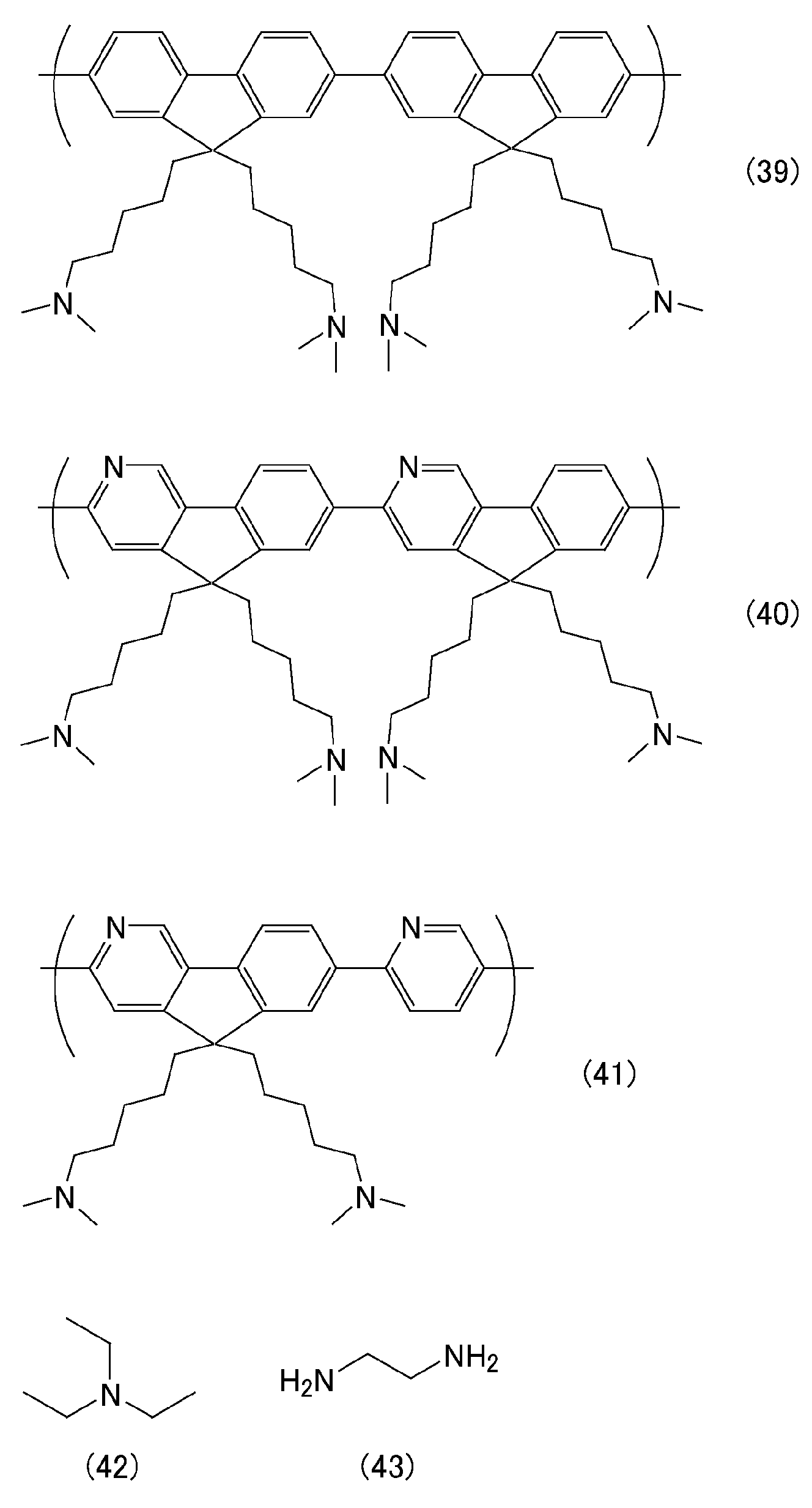
상기 버퍼층은, 환원제를 포함하는 것이어도 된다. 환원제는 n-도펀트로서 작용하기 때문에, 버퍼층이 환원제를 포함함으로써 음극으로부터 발광층으로의 전자의 공급이 충분히 실시되기 때문에, 발광의 효율이 향상된다.The buffer layer may contain a reducing agent. Since the reducing agent acts as an n-dopant, the buffer layer contains a reducing agent, so that the electrons are sufficiently supplied from the cathode to the light emitting layer, so that the efficiency of light emission is improved.
상기 버퍼층이 포함하는 환원제는, 전자 공여성의 화합물이면 특별히 제한되지 않지만, 1,3-디메틸-2,3-디하이드로-1H-벤조[d]이미다졸, 1,3-디메틸-2-페닐-2,3-디하이드로-1H-벤조[d]이미다졸, (4-(1,3-디메틸-2,3-디하이드로-1H-벤조이미다졸-2-일)페닐)디메틸아민 (N-DMBI), 1,3,5-트리메틸-2-페닐-2,3-디하이드로-1H-벤조[d]이미다졸 등의 2,3-디하이드로벤조[d]이미다졸 화합물 ; 3-메틸-2-페닐-2,3-디하이드로벤조[d]티아졸 등의 2,3-디하이드로벤조[d]티아졸 화합물 ; 3-메틸-2-페닐-2,3-디하이드로벤조[d]옥사졸 등의 2,3-디하이드로벤조[d]옥사졸 화합물 ; 류코 크리스탈 바이올렛 (= 트리스(4-디메틸아미노페닐)메탄), 류코 말라카이트 그린 (= 비스(4-디메틸아미노페닐)페닐메탄), 트리페닐메탄 등의 트리페닐메탄 화합물 ; 2,6-디메틸-1,4-디하이드로피리딘-3,5-디카르복실산디에틸 (한츠 에스테르) 등의 디하이드로피리딘 화합물 등의 1 종 또는 2 종 이상을 사용할 수 있다. 이 중에서도, 2,3-디하이드로벤조[d]이미다졸 화합물이나, 디하이드로피리딘 화합물이 바람직하다. 보다 바람직하게는, (4-(1,3-디메틸-2,3-디하이드로-1H-벤조이미다졸-2-일)페닐)디메틸아민 (N-DMBI), 또는 2,6-디메틸-1,4-디하이드로피리딘-3,5-디카르복실산디에틸 (한츠 에스테르) 이다.The reducing agent contained in the buffer layer is not particularly limited as long as it is a compound of an electron donating compound, but 1,3-dimethyl-2,3-dihydro-1H-benzo [d] imidazole, Benzo [d] imidazole, (4- (1,3-dimethyl-2,3-dihydro-1H-benzoimidazol- 2,3-dihydrobenzo [d] imidazole compounds such as 1,3,5-trimethyl-2-phenyl-2,3-dihydro-1H-benzo [d] imidazole; 2,3-dihydrobenzo [d] thiazole compounds such as 3-methyl-2-phenyl-2,3-dihydrobenzo [d] thiazole; 2,3-dihydrobenzo [d] oxazole compounds such as 3-methyl-2-phenyl-2,3-dihydrobenzo [d] oxazole; Triphenylmethane compounds such as leuco crystal violet (= tris (4-dimethylaminophenyl) methane), leuco malachite green (= bis (4-dimethylaminophenyl) phenylmethane), and triphenylmethane; Dihydropyridine compounds such as 2,6-dimethyl-1,4-dihydropyridine-3,5-dicarboxylic acid diethyl (Hans ester), and the like. Among them, 2,3-dihydrobenzo [d] imidazole compounds and dihydropyridine compounds are preferable. (N-DMBI), or 2,6-dimethyl-1, 3-dihydro-1H-benzoimidazol- , 4-dihydropyridine-3,5-dicarboxylic acid diethyl (hans ester).
상기 버퍼층이 포함하는 환원제의 양은, 버퍼층을 형성하는 유기 화합물 100 질량% 에 대하여, 0.1 ∼ 15 질량% 인 것이 바람직하다. 환원제를 이와 같은 비율로 포함하면, 유기 전계 발광 소자의 발광 효율을 충분히 높은 것으로 할 수 있다. 보다 바람직하게는, 버퍼층을 형성하는 유기 화합물 100 질량% 에 대하여, 0.5 ∼ 10 질량% 이고, 더욱 바람직하게는, 0.5 ∼ 5 질량% 이다.The amount of the reducing agent contained in the buffer layer is preferably 0.1 to 15 mass% with respect to 100 mass% of the organic compound forming the buffer layer. When the reducing agent is contained at such a ratio, the luminous efficiency of the organic electroluminescent device can be made sufficiently high. More preferably, it is 0.5 to 10% by mass, and more preferably 0.5 to 5% by mass, based on 100% by mass of the organic compound forming the buffer layer.
본 발명의 전계 발광 소자는, 양극과 음극 사이에 전압 (통상적으로는 15 볼트 이하) 을 인가함으로써 발광시킬 수 있다. 통상적으로는 직류 전압을 인가하지만, 교류 성분이 포함되어 있어도 된다.The electroluminescent element of the present invention can emit light by applying a voltage (typically 15 volts or less) between the anode and the cathode. Normally, a direct current voltage is applied, but an alternating current component may be included.
본 발명의 유기 전계 발광 소자는, 엄밀한 봉지가 실시된 종래의 유기 전계 발광 소자에 비하여 간이의 봉지이면서, 양호한 연속 구동 수명, 및, 보존 안정성을 갖는 것이다. 또한, 유기 화합물층의 재료를 적절히 선택함으로써 발광색을 변화시킬수 있고, 컬러 필터 등을 병용하여 원하는 발광색을 얻을 수도 있다. 이 때문에, 표시 장치나 조명 장치의 재료로서 바람직하게 사용할 수 있는 것이다.INDUSTRIAL APPLICABILITY The organic electroluminescent device of the present invention has simple sealing, good continuous driving life, and storage stability as compared with the conventional organic electroluminescent device in which strict sealing is performed. Further, the luminescent color can be changed by appropriately selecting the material of the organic compound layer, and a desired luminescent color can be obtained by using a color filter or the like in combination. Therefore, it can be preferably used as a material for a display device or a lighting device.
이와 같은, 본 발명의 유기 전계 발광 소자를 이용하여 형성되는 표시 장치도 또한, 본 발명의 하나이다. 또한 본 발명의 유기 전계 발광 소자를 이용하여 형성되는 조명 장치도 또한, 본 발명의 하나이다.Such a display device formed using the organic electroluminescent device of the present invention is also one of the present invention. Further, a lighting device formed using the organic electroluminescent device of the present invention is also one of the present invention.
본 발명의 유기 전계 발광 소자는, 상기 서술한 구성으로 이루어지고, 종래의 유기 전계 발광 소자와 같은 엄밀한 봉지를 필요로 하지 않고 양호한 연속 구동 수명, 및, 보존 안정성을 갖는 것이다. 또한, 발광층의 재료나 소자의 층 구성을 상기 서술한 바람직한 구성으로 함으로써, 더욱 발광 특성 등이 우수한 것으로 할 수 있는 점에서, 표시 장치나 조명 장치의 재료 등에 바람직하게 사용할 수 있다.The organic electroluminescent device of the present invention has the above-described structure and does not require strict sealing like the conventional organic electroluminescent device, and has a good continuous driving life and storage stability. In addition, the material of the light-emitting layer and the layer structure of the device have the above-described preferable constitution, so that the light-emitting layer can be further advantageously used for a display device or a material of a lighting device.
도 1 은 본 발명의 봉지 구조를 포함하는 유기 전계 발광 소자의 구조의 일례를 나타낸 개략도이다.
도 2 는 합성예 5 로 제조한 붕소 함유 중합체 C 의 1H-NMR 의 측정 결과를 나타낸 도면이다.
도 3 은 실시예 1 로 제작한 유기 전계 발광 소자 1 의 6 V 하에서의 1 일 후, 12 일 후, 80 일 후, 336 일 후의 EL 발광 사진 (삽입도는 5 V 의 EL 발광 사진) 을 나타낸 도면이다.
도 4 는 실시예 2 로 제작한 유기 전계 발광 소자 3 의 4 V 하에서의 1 일 후, 14 일 후, 93 일 후의 EL 발광 사진 (삽입도는 3 V 혹은 3.3 V 의 EL 발광 사진) 을 나타낸 도면이다.
도 5 는 비교예 1 로 제작한 유기 전계 발광 소자 4 의 4 V 하에서의 1 일 후, 14 일 후, 93 일 후의 EL 발광 사진 (삽입도는 3 V 의 EL 발광 사진) 을 나타낸 도면이다.
도 6 은 실시예 3 으로 제작한 유기 전계 발광 소자 4 의 6 V 하에서의 2 일 후, 12 일 후, 80 일 후의 EL 발광 사진을 나타낸 도면이다.
도 7 은 실시예 4 로 제작한 유기 전계 발광 소자 5 의 6 V 하에서의 1 일 후, 12 일 후, 80 일 후, 336 일 후, 384 일 후의 EL 발광 사진을 나타낸 도면이다.
도 8 은 실시예 6 으로 제작한 유기 전계 발광 소자 7 의 6 V 하에서의 1 일 후, 17 일 후의 EL 발광 사진을 나타낸 도면이다.
도 9 는 비교예 2 로 제작한 유기 전계 발광 소자 8 의 6 V 하에서의 7 일 후의 EL 발광 사진을 나타낸 도면이다.
도 10 은 실시예 4 로 제작한 유기 전계 발광 소자 5 의, 봉지 직후 A (초기), 봉지 직후 B (초기), 398 일 후의 전압-휘도 특성을 나타낸 도면이다.1 is a schematic view showing an example of the structure of an organic electroluminescent device including the encapsulation structure of the present invention.
Fig. 2 is a diagram showing the results of 1 H-NMR measurement of the boron-containing polymer C prepared in Synthesis Example 5. Fig.
FIG. 3 is a photograph showing EL light emission (EL light emission of 5 V in the inset) after 1 day, 12 days, 80 days, and 336 days under 6 V of the
4 is a diagram showing the EL light emission (EL light emission at 3 V or 3.3 V insertion) after 1 day, 14 days, and 93 days after the organic electroluminescent device 3 manufactured in Example 2 at 4 V .
Fig. 5 is a diagram showing EL light emission (EL light emission of 3 V in the inset) after 1 day, 14 days, and 93 days at 4 V of the
6 is a graph showing EL light emission at 2 days, 12 days, and 80 days after the
FIG. 7 is a graph showing EL light emission at 1 day, 12 days, 80 days, 336 days, and 384 days after 6 V of the
8 is a view showing EL light emission images of the
Fig. 9 is a graph showing EL light emission of the
10 is a graph showing the voltage-luminance characteristics of the
이하에 실시예를 들어 본 발명을 더욱 상세하게 설명하지만, 본 발명은 이들 실시예에만 한정되는 것은 아니다. 또한, 특별히 언급이 없는 한, 「부」 는 「중량부」 를, 「%」 는 「질량%」 를 의미하는 것으로 한다.Hereinafter, the present invention will be described in more detail with reference to examples, but the present invention is not limited to these examples. Unless otherwise stated, " part " means " part by weight " and "% " means "% by mass ".
합성예 1 (붕소 함유 화합물 A 의 합성)Synthesis Example 1 (Synthesis of boron-containing compound A)
100 ㎖ 2 구 가지형 플라스크에, 2-(디벤조보롤릴페닐)-5-브로모피리딘 (2.6 g, 6.5 m㏖), 2,7-비스(4,4,5,5-테트라메틸-1,3,2-디옥사보롤라닐)-9,9'-스피로플루오렌 (1.5 g, 2.7 m㏖), Pd(PtBu3)2 (170 ㎎, 0.32 m㏖) 를 넣었다. 플라스크 내를 질소 분위기하로 하고, THF (65 ㎖) 를 첨가하여, 교반하였다.(2.6 g, 6.5 mmol), 2,7-bis (4,4,5,5-tetramethyl-benzoimidazol-2-yl) 1,3,2- dioxa beam roller was placed carbonyl) -9,9'- spiro-fluorene (1.5 g, 2.7 m㏖), Pd (P t Bu 3) 2 (170 ㎎, 0.32 m㏖). The inside of the flask was put under a nitrogen atmosphere, THF (65 ml) was added, and the mixture was stirred.
여기에, 2 M 인산삼칼륨 수용액 (11 ㎖, 22 m㏖) 을 첨가하고, 70 ℃ 에서 환류시키면서 가열 교반하였다. 12 시간 후, 실온까지 냉각시키고, 반응 용액을 분액 깔때기로 옮겨 물을 첨가하고, 아세트산에틸로 추출하였다. 유기층을 3 N 염산, 물, 포화 식염수로 세정한 후, 황산마그네슘으로 건조시켰다. 여과한 여과액을 농축하고, 얻어진 고체를 메탄올로 세정하여, 2,7-비스(3-디벤조보롤릴-4-피리딜페닐)-9,9'-스피로플루오렌 (붕소 함유 화합물 A) 을 수율 47 % 로 얻었다 (1.2 g, 1.3 m㏖).To this, a 2M aqueous solution of tripotassium phosphate (11 ml, 22 mmol) was added, and the mixture was heated and stirred while being refluxed at 70 占 폚. After 12 hours, the reaction solution was cooled to room temperature, the reaction solution was transferred to a separatory funnel, water was added, and the mixture was extracted with ethyl acetate. The organic layer was washed with 3 N hydrochloric acid, water and saturated brine, and dried over magnesium sulfate. The filtrate was concentrated, and the obtained solid was washed with methanol to obtain 2,7-bis (3-dibenzoborolyl-4-pyridylphenyl) -9,9'-spirofluorene (boron-containing compound A) Was obtained in a yield of 47% (1.2 g, 1.3 mmol).
그 물성치는 이하와 같았다.The properties were as follows.

또한, 합성예 1 의 반응은, 하기 반응식 (44) 와 같이 나타낸다.The reaction of Synthesis Example 1 is shown in the following reaction formula (44).
[화학식 37](37)

합성예 2 (붕소 화합물 1 의 합성)Synthesis Example 2 (Synthesis of boron compound 1)
아르곤 분위기하, 5-브로모-2-(4-브로모페닐)피리딘 (94 ㎎, 0.30 m㏖) 을 포함하는 디클로로메탄 용액 (0.3 ㎖) 에, 에틸디이소프로필아민 (39 ㎎, 0.30 m㏖) 을 첨가한 후, 0 ℃ 에서 삼브롬화붕소 (1.0 M 디클로로메탄 용액, 0.9 ㎖, 0.9 m㏖) 를 첨가하고, 실온에서 9 시간 교반하였다. 반응 용액을 0 ℃ 까지 냉각시킨 후, 포화 탄산칼륨 수용액을 첨가하고, 클로로포름으로 추출하였다. 유기층을 포화 식염수로 세정하고, 황산마그네슘으로 건조시키고 여과하였다. 여과액을 로터리 이배퍼레이터로 농축한 후, 생성된 백색 고체를 여과 채취하고, 헥산으로 세정함으로써, 붕소 화합물 1 (40 ㎎, 0.082 m㏖) 을 수율 28 % 로 얻었다. 이 반응은, 하기 식 (45) 의 반응이다.To a dichloromethane solution (0.3 mL) containing 5-bromo-2- (4-bromophenyl) pyridine (94 mg, 0.30 mmol) under argon atmosphere was added ethyldiisopropylamine (39 mg, 0.30 m Mol), boron tribromide (1.0 M dichloromethane solution, 0.9 ml, 0.9 mmol) was added at 0 ° C, and the mixture was stirred at room temperature for 9 hours. The reaction solution was cooled to 0 deg. C, and a saturated aqueous potassium carbonate solution was added thereto, followed by extraction with chloroform. The organic layer was washed with saturated brine, dried over magnesium sulfate and filtered. The filtrate was concentrated with a rotary evaporator, and the resulting white solid was collected by filtration and washed with hexane to obtain a boron compound 1 (40 mg, 0.082 mmol) in a yield of 28%. This reaction is the reaction of the following formula (45).
그 물성치는 이하와 같았다.The properties were as follows.

[화학식 38](38)

합성예 3 (붕소 화합물 2 의 합성)Synthesis Example 3 (Synthesis of boron compound 2)
50 ㎖ 2 구 플라스크에 마그네슘 (561 ㎎, 23.1 m㏖) 을 넣고 반응 용기 내를 질소 분위기하로 한 후, 시클로펜틸메틸에테르 (10 ㎖) 를 넣고, 요오드를 약간 투입하고, 착색이 없어질 때까지 교반하였다. 여기에 2,2'-디브로모비페닐 (3.0 g, 9.6 m㏖) 의 시클로펜틸메틸에테르 용액 (9 ㎖) 을 적하하고, 실온에서 12 시간, 50 ℃ 에서 1 시간 교반하여 Grignard 시약을 조제하였다.Magnesium (561 mg, 23.1 mmol) was added to a 50 mL two-necked flask, and the inside of the reaction vessel was put under a nitrogen atmosphere. Cyclopentyl methyl ether (10 mL) was added thereto, and iodine was slightly added. Lt; / RTI > Cyclopentyl methyl ether solution (9 ml) of 2,2'-dibromobiphenyl (3.0 g, 9.6 mmol) was added dropwise and stirred at room temperature for 12 hours and at 50 ° C for 1 hour to prepare a Grignard reagent .
다른 200 ㎖ 3 구 플라스크에 붕소 화합물 1 (3.71 g, 7.7 m㏖) 을 넣고 질소 분위기하로 한 후, 톨루엔 (77 ㎖) 을 넣었다. 이것을 -78 ℃ 에서 교반하면서 상기 Grignard 시약을 캐뉼러로 한 번에 첨가하였다. 10 분 교반 후, 실온까지 승온하고 추가로 12 시간 교반하였다. 이 반응 용액에 물을 첨가하고, 톨루엔으로 추출하였다. 유기층을 포화 식염수로 세정하고, 황산마그네슘으로 건조시키고 여과하였다. 여과액을 농축시켜 잔류물을 칼럼 크로마토그래피로 정제함으로써 붕소 화합물 2 를 3.0 g (수율 82 %) 얻었다. 이 반응은, 하기 식 (46) 의 반응이다.Boron compound 1 (3.71 g, 7.7 mmol) was added to another 200 mL three-necked flask, and the mixture was put under a nitrogen atmosphere, followed by the addition of toluene (77 mL). The Grignard reagent was cannulated in one portion with stirring at -78 < 0 > C. After stirring for 10 minutes, the mixture was warmed to room temperature and further stirred for 12 hours. Water was added to this reaction solution and extracted with toluene. The organic layer was washed with saturated brine, dried over magnesium sulfate and filtered. The filtrate was concentrated, and the residue was purified by column chromatography to obtain 3.0 g (yield 82%) of boron compound 2. This reaction is the reaction of the following formula (46).
그 물성치는 이하와 같았다.The properties were as follows.

[화학식 39][Chemical Formula 39]

합성예 4 (붕소 함유 화합물 B 의 합성)Synthesis Example 4 (Synthesis of boron-containing compound B)
100 ㎖ 2 구 플라스크에 붕소 화합물 2 (2.0 g, 4.2 m㏖), Pd(PPh3)4 (240 ㎎, 0.21 m㏖) 를 넣고, 반응 용기 내를 질소 분위기하로 하였다. 여기에 톨루엔 (21 ㎖), 트리부틸(2-피리딜)주석 (3.7 g, 10.1 m㏖) 을 넣고, 120 ℃ 에서 하룻밤 교반하였다. 반응 종료 후, 농축하고, 잔류물을 칼럼 크로마토그래피로 정제함으로써 본 발명의 붕소 함유 화합물 B 를 800 ㎎ 얻었다 (수율 40 %). 이 반응은, 하기 식 (47) 의 반응이다.100 ㎖ 2 into a boron compound 2 (2.0 g, 4.2 m㏖) , Pd (PPh 3) 4 (240 ㎎, 0.21 m㏖) in necked flask, a reaction vessel was Haro nitrogen atmosphere. Toluene (21 ml) and tributyl (2-pyridyl) tin (3.7 g, 10.1 mmol) were added thereto and stirred overnight at 120 ° C. After completion of the reaction, the reaction mixture was concentrated, and the residue was purified by column chromatography to obtain 800 mg of the boron-containing compound B of the present invention (yield: 40%). This reaction is the reaction of the following formula (47).
그 물성치는 이하와 같았다.The properties were as follows.


[화학식 40](40)

합성예 5 (붕소 함유 화합물 C (붕소 함유 중합체) 의 합성)Synthesis Example 5 (Synthesis of boron-containing compound C (boron-containing polymer)
쉬링크 플라스크에 붕소 화합물 2 (474 ㎎, 1.00 m㏖), 9,9-디옥틸플루오렌-2,7-보론산-비스(프로판디올)에스테르 (568 ㎎, 1.02 m㏖) 를 넣고, 반응 용기 내를 질소 분위기하로 한 후, THF (6 ㎖) 를 넣어 용해시켰다. 여기에 35 wt% 수산화테트라에틸암모늄 (1.68 ㎖, 3.99 m㏖), 물 (2.2 ㎖), Aliquat (등록상표) (40 ㎎, 0.10 m㏖) 의 톨루엔 용액 (6 ㎖) 을 첨가하였다. 90 ℃ 로 가열하고, Pd(PPh3)4 (23 ㎎, 0.020 m㏖) 를 넣고, 90 ℃ 에서 12 시간 교반하였다. 브로모벤젠 (204 ㎎, 1.30 m㏖) 을 첨가하여 5 시간 교반 후, 페닐보론산 (572 ㎎, 4.69 m㏖) 을 첨가하여 하룻밤 교반하였다. 실온까지 냉각 후, 반응 용액을 톨루엔으로 희석하여 유기층을 물로 세정하고, 황산마그네슘으로 건조시켰다. 여과하여 농축 후 잔류물을 클로로포름에 용해시켜, 실리카 겔 쇼트 칼럼에 통과시켰다. 이 용액을 농축하고, 메탄올에 투입하여 얻어지는 황색 침전물을 여과 채취하여, 붕소 함유 화합물 C (붕소 함유 중합체) 를 386 ㎎ 얻었다. 이 반응은, 하기 식 (48) 의 반응이다. 붕소 함유 화합물 C 의 1H-NMR 측정 결과를 도 2 에 나타낸다.Boron compound 2 (474 mg, 1.00 mmol) and 9,9-dioctylfluorene-2,7-boronic acid-bis (propanediol) ester (568 mg, 1.02 mmol) The inside of the vessel was put under a nitrogen atmosphere, and THF (6 ml) was added to dissolve it. To this was added a toluene solution (6 mL) of 35 wt% tetraethylammonium hydroxide (1.68 mL, 3.99 mmol), water (2.2 mL) and Aliquat (40 mg, 0.10 mmol). And heated to 90 ℃, Pd (PPh 3) into a 4 (23 ㎎, 0.020 m㏖) , and the mixture was stirred for 12 hours at 90 ℃. Bromobenzene (204 mg, 1.30 mmol) was added and stirred for 5 hours, then phenylboronic acid (572 mg, 4.69 mmol) was added and the mixture was stirred overnight. After cooling to room temperature, the reaction solution was diluted with toluene, and the organic layer was washed with water and dried with magnesium sulfate. After filtration and concentration, the residue was dissolved in chloroform and passed through a silica gel short column. This solution was concentrated and charged in methanol. The resulting yellow precipitate was filtered to obtain 386 mg of a boron-containing compound C (boron-containing polymer). This reaction is the reaction of the following formula (48). The results of 1 H-NMR measurement of the boron-containing compound C are shown in Fig.
얻어진 붕소 함유 중합체는, Mn = 14,304, Mw = 36,646, PDI = 2.56 이었다.The obtained boron-containing polymer had Mn = 14,304, Mw = 36,646 and PDI = 2.56.
[화학식 41](41)

(실시예 1)(Example 1)
[1] 시판되고 있는 평균 두께 0.7 ㎜ 의 ITO 전극층이 형성된 투명 유리 기판을 준비하였다. 이 때, 기판의 ITO 전극 (음극) 은 폭 2 ㎜ 로 패터닝되어 있는 것을 사용하였다. 이 기판을 아세톤 중, 이소프로판올 중에서 각각 10 분간 초음파 세정 후, 이소프로판올 중에서 5 분간 자비하였다. 이 기판을 이소프로판올 중으로부터 취출하고, 질소 블로우에 의해 건조시켜, UV 오존 세정을 20 분 실시하였다.[1] A transparent glass substrate on which a commercially available ITO electrode layer having an average thickness of 0.7 mm was formed was prepared. At this time, the ITO electrode (cathode) of the substrate was patterned with a width of 2 mm. This substrate was ultrasonically cleaned in acetone and isopropanol for 10 minutes, respectively, and then was boiled for 5 minutes in isopropanol. The substrate was taken out from isopropanol, dried by nitrogen blow, and subjected to UV ozone cleaning for 20 minutes.
[2] 이 기판을, 아연 금속 타겟을 가지는 미러 트론 스퍼터 장치의 기판 홀더에 고정시켰다. 약 1 × 10⁻⁴ ㎩ 까지 감압한 후, 아르곤과 산소를 도입한 상태로 스퍼터하여, 막두께 약 2 ㎚ 의 산화아연층을 제조하였다. 이 때에 메탈 마스크를 병용하여, 전극 취출을 위하여 ITO 전극의 일부는 산화아연이 제막되지 않도록 하였다.[2] This substrate was fixed to a substrate holder of a mirrortron sputtering apparatus having a zinc metal target. After the pressure was reduced to about 1 x 10 < -4 > Pa, sputtering was performed with argon and oxygen introduced to prepare a zinc oxide layer having a thickness of about 2 nm. At this time, a metal mask was used in combination so that zinc oxide was not formed on a part of the ITO electrode for electrode extraction.
[3] 버퍼층으로서 붕소 함유 화합물 A 의 1 중량%, (4-(1,3-디메틸-2,3-디하이드로-1H-벤조이미다졸-2-일)페닐)디메틸아민 (N-DMBI) 의 0.01 중량% 1,2-디클로로에탄 혼합 용액을 제작하였다. 공정 [2] 로 제작한 산화아연 박막이 형성된 기판을 스핀 코터에 세트하였다. 이 기판 상에 붕소 함유 화합물 A, N-DMBI 혼합 용액을 적하하고, 매분 2000 회전으로 30 초간 회전시켜, 붕소 함유 유기 화합물을 포함하는 버퍼층을 형성하였다. 또한, 이것을 질소 분위기하 100 ℃ 로 세트한 핫 플레이트로 1 시간 어닐 처리를 실시하였다. 버퍼층의 평균 두께는 30 ㎚ 였다.(3-dimethyl-2,3-dihydro-1H-benzoimidazol-2-yl) phenyl) dimethylamine (N-DMBI) as a buffer layer, To prepare a mixed solution of 0.01% by weight of 1,2-dichloroethane. The substrate on which the zinc oxide thin film prepared in the process [2] was formed was set in a spin coater. A boron-containing compound A and an N-DMBI mixed solution were dropped onto the substrate and rotated at 2000 rpm for 30 seconds to form a buffer layer containing a boron-containing organic compound. Further, this was annealed for 1 hour on a hot plate set at 100 캜 under a nitrogen atmosphere. The average thickness of the buffer layer was 30 nm.
[4] 붕소 함유 화합물의 층까지 형성한 기판을 진공 증착 장치의 기판 홀더에 고정시켰다. 비스[2-(2'-하이드록시페닐)피리딘]베릴륨 (Bepp2), 트리스[3-메틸-2-페닐피리딘]이리듐 (III) (Ir(mpy)3), N,N'-디(1-나프틸)-N,N'-디페닐-1,1'-비페닐-4,4'-디아민 (α-NPD) 을 각각 알루미나 도가니에 넣어 증착원으로 세트하였다. 진공 증착 장치 내를 약 1 × 10⁻⁵ ㎩ 까지 감압하고, Bepp2 를 호스트, (Ir(mpy)3) 를 도펀트로서 35 ㎚ 공증착하여, 발광층을 제막하였다. 이 때, 도프 농도는 (Ir(mpy)3) 가 발광층 전체에 대하여 6 % 가 되도록 하였다. 다음으로, α-NPD 를 60 ㎚ 증착하고, 정공 수송층을 제막하였다. 다음으로, 한 번 질소 퍼지한 후, 삼산화몰리브덴, 금을 알루미나 도가니에 넣어 증착원으로 세트하였다. 진공 증착 장치 내를 약 1 × 10⁻⁵ ㎩ 까지 감압하고, 삼산화몰리브덴 (제 2 금속 산화물층) 을 막두께 10 ㎚ 가 되도록 증착하였다. 다음으로, 금 (양극) 을 막두께 50 ㎚ 가 되도록 증착하여, 유기 전계 발광 소자 3 을 제작하였다. 제 2 전극을 증착할 때, 스테인리스제의 증착 마스크를 이용하여 증착면이 폭 2 ㎜ 의 띠상이 되도록 하였다. 즉, 제작한 유기 전계 발광 소자의 발광 면적은, 4 ㎟ 로 하였다.[4] The substrate formed up to the layer of the boron-containing compound was fixed to the substrate holder of the vacuum vapor deposition apparatus. Bis [2- (2'-hydroxy-phenyl) pyridine] beryllium (Bepp 2), tris [3-methyl-2-phenyl pyridine] iridium (III) (Ir (mpy) 3), N, N'- di ( (1-naphthyl) -N, N'-diphenyl-1,1'-biphenyl-4,4'-diamine (? -NPD) were respectively placed in an alumina crucible and set as an evaporation source. The inside of the vacuum evaporation apparatus was reduced to about 1 x 10 < -5 > Pa, Bepp 2 was host and Ir (mpy) 3 was co-deposited with 35 nm as a dopant to form a light emitting layer. At this time, the doping concentration was set such that (Ir (mpy) 3 ) was 6% with respect to the entire luminescent layer. Next, α-NPD was deposited to 60 nm, and a hole transport layer was formed. Next, after nitrogen purge once, molybdenum trioxide and gold were placed in an alumina crucible and set as an evaporation source. The inside of the vacuum evaporation apparatus was reduced to about 1 x 10 < -5 > Pa and molybdenum trioxide (second metal oxide layer) was deposited to a film thickness of 10 nm. Next, gold (anode) was vapor-deposited so as to have a film thickness of 50 nm, thereby fabricating the organic electroluminescent device 3. When depositing the second electrode, a deposition mask made of stainless steel was used to make the deposition surface have a width of 2 mm. That is, the light emitting area of the fabricated organic electroluminescent device was 4 mm 2.
[5] [4] 까지로 제작한 소자의 주위 (소자 형성 에어리어보다 크고 기판보다 작은 부위) 에 UV 경화 수지를 도포하고, 그 위에 동사이즈의 유리 프레임을 설치, 추가로 그 위에 UV 경화 수지를 도포하고, 마지막으로 오이케 공업사 제조 봉지 필름 (수분 투과율 3 × 10⁻⁴ g/㎡·day) 을 부착하여, UV 에 의해 경화시켰다. 이로써 유기 전계 발광 소자 1 을 제작하였다.[5] [4] A UV curable resin was applied to the periphery of the device (larger than the element formation area and smaller than the substrate), a glass frame of the same size was placed thereon, and a UV curable resin Finally, a sealing film (moisture permeability: 3 × 10 -4 g / m 2 · day) manufactured by Oike Kogyo Co., Ltd. was attached and cured by UV. Thus, the
(실시예 2)(Example 2)
공정 [3] 을 하기 공정 [3-2] 로 한 것 이외에는 실시예 1 과 동일하게 하여, 유기 전계 발광 소자 2 를 제작하였다. 또한, 버퍼층의 평균 두께는, 6 ㎚ 였다.Organic electroluminescent element 2 was fabricated in the same manner as in Example 1 except that the step [3] was changed to the following step [3-2]. The average thickness of the buffer layer was 6 nm.
[3-2] 다음으로 버퍼층으로서 닛폰 촉매사 제조 폴리에틸렌이민 (등록상표 : 에포민) 을 에탄올에 의해 0.5 중량% 로 희석한 것을 2000 rpm 30 초의 조건으로 스핀 코트한다. 여기서 사용한 에포민은 분자량 70000 의 P1000 이다.[3-2] Next, as a buffer layer, polyethyleneimine (registered trademark: epomin) manufactured by Nippon Catalysts Co., Ltd., diluted with ethanol to 0.5 wt%, is spin-coated under the condition of 2000 rpm for 30 seconds. The epomin used here is P1000 with a molecular weight of 70000.
(비교예 1)(Comparative Example 1)
실시예 2 의 공정 [5] 에 있어서, 오이케 공업사 제조 봉지 필름 (수분 투과율 3 × 10⁻⁴ g/㎡·day) 대신에, 유리를 봉지 기재로서 사용한 것 이외에는 실시예 2 와 동일하게 하여, 유기 전계 발광 소자 3 을 제작하였다.The same procedure as in Example 2 was carried out except that glass was used as a sealing material in place of the sealing film (moisture permeability: 3 × 10 -4 g / m 2 · day) manufactured by Oike Kogyo Co., Ltd. in the step [5] Thereby preparing an organic electroluminescent device 3.
(실시예 3)(Example 3)
실시예 1 의 공정 [3] 에 있어서, 버퍼층의 평균 두께를 60 ㎚ 로 한 것 이외에는 실시예 1 과 동일하게 하여 유기 전계 발광 소자 4 를 제작하였다.An
(실시예 4)(Example 4)
실시예 1 의 공정 [3] 에 있어서, 버퍼층의 평균 두께를 10 ㎚ 로 한 것 이외에는 실시예 1 과 동일하게 하여 유기 전계 발광 소자 5 를 제작하였다.An
(실시예 5)(Example 5)
공정 [3] 을 하기 공정 [3-3] 으로 한 것 이외에는 실시예 1 과 동일하게 하여, 유기 전계 발광 소자 6 을 제작하였다. 또한, 버퍼층의 평균 두께는, 10 ㎚ 였다.An
[3-3] 다음으로 버퍼층으로서 붕소 함유 화합물 A 를, 환원제를 넣지 않고, 1,2-디클로로에탄에 의해 0.25 중량% 로 희석한 것을 2000 rpm 30 초의 조건으로 스핀 코트한다.[3-3] Next, the boron-containing compound A as a buffer layer was diluted with 1,2-dichloroethane to 0.25 wt% without adding a reducing agent, and spin-coated at 2000 rpm for 30 seconds.
(실시예 6)(Example 6)
실시예 5 내의 공정 [5] 에 있어서, 오이케 공업사 제조 봉지 필름 (수분 투과율 3 × 10⁻⁴ g/㎡·day) 대신에, 오이케 공업사 제조 필름 (수분 투과율 3 × 10⁻³ g/㎡·day) 을 봉지 기재로서 사용한 것 이외에는 실시예 5 와 동일하게 하여, 유기 전계 발광 소자 7 을 제작하였다.In Example 5 the process [5] in, Oike Industries Co. sealant film (moisture permeability 3 × 10 -4 g / ㎡ · day) instead, Oike Ind prepared film (moisture permeability 3 × 10 -3 g / ㎡ The
(비교예 2)(Comparative Example 2)
공정 [3] 을 하기 공정 [3-4] 로 하고, 공정 [5] 에 있어서, 오이케 공업사 제조 봉지 필름 (수분 투과율 3 × 10⁻⁴ g/㎡·day) 대신에, 오이케 공업사 제조 필름 (수분 투과율 5 × 10⁻² g/㎡·day) 을 봉지 기재로서 사용한 것 이외에는 실시예 1 과 동일하게 하여, 유기 전계 발광 소자 8 을 제작하였다. 또한, 버퍼층의 평균 두께는, 30 ㎚ 였다.[Step 3] is carried out in the following step [3-4]. In step [5], a sealing film (moisture permeability: 3 x 10 -4 g / m 2 · day) manufactured by Oike Kogyo Co., (Moisture permeability: 5 x 10 < -2 & gt ; g / m < 2 > day) was used as the encapsulating substrate. The average thickness of the buffer layer was 30 nm.
[3-4] 다음으로 버퍼층으로서 붕소 함유 화합물 B 를, 환원제를 넣지 않고, 테트라하이드로푸란에 의해 1 중량% 로 희석한 것을 2000 rpm 30 초의 조건으로 스핀 코트한다.[3-4] Next, the boron-containing compound B as a buffer layer is diluted to 1 wt% with tetrahydrofuran, without adding a reducing agent, and spin-coated at 2000 rpm for 30 seconds.
(실시예 7)(Example 7)
비교예 2 내의 공정 [5] 에 있어서, 오이케 공업사 제조 봉지 필름 (수분 투과율 5 × 10⁻² g/㎡·day) 대신에, 오이케 공업사 제조 필름 (수분 투과율 3 × 10⁻⁴ g/㎡·day) 을 봉지 기재로서 사용한 것 이외에는 비교예 2 와 동일하게 하여, 유기 전계 발광 소자 9 를 제작하였다.(Moisture permeability: 3 x 10 < -4 > g / m < 2 >) was used in place of the sealing film (moisture permeability: 5 x 10⁻² g / m2day) manufactured by Oike Kogyo Co., The
(실시예 8)(Example 8)
비교예 2 내의 공정 [5] 에 있어서, 오이케 공업사 제조 봉지 필름 (수분 투과율 5 × 10⁻² g/㎡·day) 대신에, 오이케 공업사 제조 필름 (수분 투과율 3 × 10⁻³ g/㎡·day) 을 봉지 기재로서 사용한 것 이외에는 비교예 2 와 동일하게 하여, 유기 전계 발광 소자 10 을 제작하였다.(Moisture permeability: 3 x 10 < -3 > g / m2) was used in place of the sealing film (moisture permeability: 5 x 10⁻² g / m2day) manufactured by Oike Kogyo Co., The
(비교예 3)(Comparative Example 3)
실시예 5 의 공정 [3-3] 에 있어서, 버퍼층의 평균 두께를 30 ㎚ 로 하고, 공정 [5] 에 있어서, 오이케 공업사 제조 봉지 필름 (수분 투과율 3 × 10⁻⁴ g/㎡·day) 대신에, 오이케 공업사 제조 필름 (수분 투과율 2 × 10⁻¹ g/㎡·day) 을 봉지 기재로서 사용한 것 이외에는 실시예 5 와 동일하게 하여, 유기 전계 발광 소자 11 을 제작하였다.(Moisture permeability: 3 × 10 -4 g / m 2 · day) manufactured by Oike Kogyo Co., Ltd. in the step [5], the average thickness of the buffer layer was 30 nm in the step [3-3] An organic electroluminescent device 11 was produced in the same manner as in Example 5 except that a film (moisture permeability: 2 x 10 -1 g / m 2 · day) manufactured by Oike Kogyo Co., Ltd. was used as the encapsulating substrate.
(실시예 9)(Example 9)
실시예 1 의 공정 [3] 을 하기 공정 [3-5] 로 한 것 이외에는 실시예 1 과 동일하게 하여, 유기 전계 발광 소자 12 를 제작하였다. 또한, 버퍼층의 평균 두께는, 30 ㎚ 였다.An organic electroluminescent element 12 was produced in the same manner as in Example 1 except that the step [3] of Example 1 was changed to the following step [3-5]. The average thickness of the buffer layer was 30 nm.
[3-5] 다음으로 버퍼층으로서 붕소 함유 화합물 C 를, 환원제를 넣지 않고, 1,2-디클로로에탄에 의해 1 중량% 로 희석한 것을 2000 rpm 30 초의 조건으로 스핀 코트한다.[3-5] Next, boron-containing compound C as a buffer layer is diluted to 1 wt% with 1,2-dichloroethane without adding a reducing agent, and spin-coated at 2000 rpm for 30 seconds.
(실시예 10)(Example 10)
실시예 1 의 공정 [1] 을 하기 공정 [1-2] 로 한 것 이외에는 실시예 1 과 동일하게 하여, 유기 전계 발광 소자 13 을 제작하였다.An organic electroluminescent element 13 was prepared in the same manner as in Example 1 except that the step [1] of Example 1 was changed to the following step [1-2].
[1-2] 시판되고 있는 ITO 전극층이 형성된 폴리에틸렌나프탈레이트 필름 기판 (수증기 투과율 10-4 g/㎡·day 이 되는 배리어 가공이 실시되어 있다) 을 준비하였다. 이 때, 기판의 ITO 전극 (음극) 은 폭 2 ㎜ 로 패터닝되어 있는 것을 사용하였다. 이 기판을 보호 필름을 박리하고, 이소프로판올 중에서 10 분간 초음파 세정 후, 이 기판을 이소프로판올 중으로부터 취출하고, 질소 블로우에 의해 건조시켜, UV 오존 세정을 20 분 실시하였다.[1-2] A polyethylene naphthalate film substrate on which a commercially available ITO electrode layer was formed (having a vapor permeability of 10 -4 g / m 2 · day was subjected to barrier processing) was prepared. At this time, the ITO electrode (cathode) of the substrate was patterned with a width of 2 mm. The substrate was peeled off from the protective film and ultrasonically cleaned in isopropanol for 10 minutes. The substrate was taken out from isopropanol, dried by nitrogen blow, and UV ozone cleaned for 20 minutes.
(유기 전계 발광 소자의 발광 관찰)(Observation of luminescence of organic electroluminescent device)
키슬리사 제조의 「2400 형 소스 미터」 에 의해, 소자에 대한 전압 인가를 실시하였다. 소자는, 각각 나타낸 기간, 대기하에 방치한 후, EL 발광의 모습을 촬영하였다. 유기 전계 발광 소자 1 ∼ 5, 7, 8 의 결과를 각각 도 3 ∼ 9 에 나타낸다.A voltage was applied to the device by a " 2400-type source meter " manufactured by Keithley Instruments. The device was left under the atmosphere for each of the periods shown, and then the state of EL light emission was photographed. The results of
(유기 전계 발광 소자의 발광 특성 측정)(Measurement of Light Emission Characteristics of Organic Electroluminescent Device)
실시예 4 로 제작한 유기 전계 발광 소자 5 에 대하여, 봉지 직후 (초기) 의 상이한 발광 에어리어 2 지점 A, B, 및, 398 일 후의 발광에 대하여, 키슬리사 제조의 「2400 형 소스 미터」 에 의해, 소자에 대한 전압 인가와 전류 측정을 실시하였다. 또한 코니카 미놀타사 제조의 「LS-100」 에 의해, 발광 휘도를 측정하였다.With respect to the
유기 전계 발광 소자를, 아르곤 분위기하 직류 전압을 인가했을 때의 전압-휘도 특성을 도 10 에 나타낸다.Fig. 10 shows voltage-luminance characteristics of the organic electroluminescent device when a direct current voltage is applied in an argon atmosphere.
실시예 1, 3, 4 로부터, 버퍼층으로서 환원제를 도프한 붕소 화합물 A 를 사용한 경우, 수분 투과율 3 × 10⁻⁴ g/㎡·day 의 봉지막에서는, 12 일 후까지 큰 다크 스폿은 보이지 않고, 특히, 버퍼층의 평균 두께가 30 ㎚, 10 ㎚ 인 실시예 1, 4 에서는, 각각 336 일 후, 384 일 후까지 큰 다크 스폿은 보이지 않는다. 또한, 실시예 4 에서는, 초기와 398 일 후의 전압-휘도 특성이 동등한 것도 확인되었다.From Examples 1, 3, and 4, when a boron compound A doped with a reducing agent was used as a buffer layer, a large dark spot was not observed until after 12 days in a sealing film having a water permeability of 3 x 10 -4 g / In particular, in Examples 1 and 4 in which the average thickness of the buffer layer is 30 nm and 10 nm, large dark spots are not observed after 336 days and 384 days, respectively. It was also confirmed in Example 4 that the voltage-luminance characteristics at the beginning and after 398 days were equivalent.
또한, 버퍼층으로서 환원제가 없는 붕소 화합물 A 를 이용하여, 수분 투과율 3 × 10⁻³ g/㎡·day 의 봉지막으로 봉지한 실시예 6 에서도, 초기에 오염으로 인한 다크 스폿은 있지만, 17 일 후에도 성장하는 모습은 없다. 또한, 실시예 6 과 동일한 환원제가 없는 붕소 화합물 A 를 이용하여, 실시예 6 보다 수분 투과율이 낮은, 실시예 1 과 동일한 봉지막으로 봉지한 실시예 5 에서도, 양호한 결과가 얻어지는 것이 확인되었다.In Example 6 in which a boron compound A free of a reducing agent was used as a buffer layer and sealed with a sealing film having a moisture permeability of 3 x 10⁻³ g / m2 占 day, dark spots due to contamination were observed initially, but after 17 days There is no growth. It was also confirmed that good results were obtained even in Example 5 in which the same boron compound A as in Example 6 was used and in which the moisture permeability was lower than that in Example 6 and the same sealing film as in Example 1 was sealed with the sealing film.
이에 반하여, 수분 투과율 5 × 10⁻² g/㎡·day 의 봉지막으로 봉지한 비교예 2 에서는, 7 일 후에 비발광부는 아니지만 암부가 관측되어 있어, 분명하게 휘도의 저하와 발광 불균일이 관측되었다. 또한, 비교예 2 보다 더욱 수분 투과율이 큰 봉지막을 사용한 비교예 3 에서는, 마찬가지로 7 일 후에 더욱 현저한 암부가 확인되었다.On the other hand, in Comparative Example 2 in which the substrate was sealed with a sealing film having a water permeability of 5 × 10 -2 g / m 2 · day, the dark portion was observed after 7 days, which was not a non-light emitting portion, . Further, in Comparative Example 3 using a sealing film having a higher water permeability than that of Comparative Example 2, a more remarkable dark portion was confirmed after 7 days as well.
비교예 2 로 나타낸 소자 구성에 있어서, 수증기 투과율을 향상시킨 봉지 필름을 사용한 경우 (실시예 7 및 실시예 8) 에 있어서는 양호한 결과를 얻었으며, 실시예 4 와 동일한 장기의 보존 안정성 (다크 스폿이 확인되지 않는 점, 그 촬영시의 전압이 변함이 없는 점으로부터 전압-휘도 특성에 큰 변화가 없다고 추측되는 것) 을 확인하였다.Good results were obtained in the case of using a sealing film having improved water vapor permeability (Example 7 and Example 8) in the device configuration shown in Comparative Example 2, and the storage stability of the same organs as in Example 4 It is presumed that there is not a large change in the voltage-luminance characteristic from the point that the voltage at the time of photographing is not changed.
동일하게, 실시예 9 에 있어서, 버퍼 재료를 붕소 화합물 C 와 같은 폴리머로 한 경우에 있어서도, 장기의 보존 안정성이 확인되었다.Likewise, in Example 9, storage stability of organ was confirmed even when the buffer material was a polymer such as boron compound C.
또한 추가로, 실시예 10 에 나타내는 바와 같이, 기판을 유리로부터 배리어 성능을 가진 필름 기판으로 변경해도, 그 장기 보존 안정성은 유지되는 것이 확인되었다.Further, as shown in Example 10, it was confirmed that even if the substrate was changed from glass to a film substrate having barrier performance, its long-term storage stability was maintained.
이상으로부터, 100 ㏅/㎡ 정도의 실용 범위의 고휘도에 있어서는, 수분 투과율 10-3 g/㎡·day 정도의 봉지 성능으로 손색 없는 것이 분명해졌다. 또한, 버퍼층으로서 폴리에틸렌이민을 사용한 경우의 비교를 실시예 2 및 비교예 1 에서 실시하였다. 유리 봉지의 결과로 아무런 손색 없는 발광이 100 일 정도까지 관측되고 있는 것을 알 수 있다. 본 비교에 의해, 본 소자 형태를 가지면, 수분 투과율 10-3 g/㎡·day 정도의 봉지 성능으로 유리 봉지의 것과 동일한 정도의 소자 특성을 장기간 관측할 수 있는 것을 나타낼 수 있었다.From the above, it has become clear that the sealing performance at a water permeability of about 10 -3 g / m 2 · day is excellent at a high luminance of a practical range of about 100 ㏅ / ㎡. Further, the comparison in the case of using polyethyleneimine as the buffer layer was carried out in Example 2 and Comparative Example 1. As a result of the glass encapsulation, it can be seen that no remarkable emission is observed up to about 100 days. According to this comparison, it was possible to observe for a long time the device characteristics of the same degree as that of the glass encapsulation with the encapsulation performance of about 10 -3 g / m 2 · day with the present device form.
1 : 기판
2 : 음극
3 : 제 1 금속 산화물층
4 : 버퍼층
5 : 유기 화합물층
6 : 제 2 금속 산화물층
7 : 양극
8 : UV 경화 수지
9 : 유리 프레임
10 : 봉지 기재1: substrate
2: cathode
3: a first metal oxide layer
4: buffer layer
5: Organic compound layer
6: a second metal oxide layer
7: anode
8: UV curing resin
9: Glass frame
10: bag material
Claims (7)
그 유기 전계 발광 소자는, 수증기 투과율이 10-6 ∼ 10-3 g/㎡·day 인 봉지가 된 것
인 것을 특징으로 하는 유기 전계 발광 소자.An organic electroluminescent device having a structure in which a plurality of layers are laminated between an anode and a cathode formed on a substrate,
The organic electroluminescent device is a sealed product having a vapor transmissivity of 10 -6 to 10 -3 g / m 2 · day
Wherein the organic electroluminescent element is an organic electroluminescent element.
상기 유기 전계 발광 소자는, 양극과 음극 사이에 금속 산화물층을 갖는 것을 특징으로 하는 유기 전계 발광 소자.The method according to claim 1,
Wherein the organic electroluminescent device has a metal oxide layer between the anode and the cathode.
상기 유기 전계 발광 소자는, 유기 화합물을 포함하는 재료에 의해 형성되는 버퍼층을 갖고,
그 유기 화합물을 포함하는 재료는, 유기 화합물에 대한 환원제의 함유량이 0.1 ∼ 15 질량% 이고,
그 버퍼층의 평균 두께는, 5 ∼ 30 ㎚ 인 것을 특징으로 하는 유기 전계 발광 소자.3. The method according to claim 1 or 2,
The organic electroluminescent device has a buffer layer formed of a material containing an organic compound,
The material containing the organic compound preferably has a reducing agent content of 0.1 to 15% by mass relative to the organic compound,
And the average thickness of the buffer layer is 5 to 30 nm.
상기 유기 전계 발광 소자는, 유기 화합물을 포함하는 재료에 의해 형성되는 버퍼층을 갖고,
그 유기 화합물을 포함하는 재료는, 유기 화합물에 대한 환원제의 함유량이 0 ∼ 0.1 질량% 이고,
그 버퍼층의 평균 두께는, 5 ∼ 60 ㎚ 인 것을 특징으로 하는 유기 전계 발광 소자.3. The method according to claim 1 or 2,
The organic electroluminescent device has a buffer layer formed of a material containing an organic compound,
The material containing the organic compound preferably has a reducing agent content of 0 to 0.1% by mass relative to the organic compound,
Wherein an average thickness of the buffer layer is 5 to 60 nm.
그 박막 재료는, 수증기 투과율이 10-6 ∼ 10-3 g/㎡·day 인 필름을 필수로 하는 것을 특징으로 하는 유기 전계 발광 소자 형성용 박막 재료.A thin film material used for forming the organic electroluminescent device according to any one of claims 1 to 4,
Wherein the thin film material comprises a film having a vapor transmissivity of 10 -6 to 10 -3 g / m 2 · day as essential.
Applications Claiming Priority (3)
| Application Number | Priority Date | Filing Date | Title |
|---|---|---|---|
| JPJP-P-2013-039902 | 2013-02-28 | ||
| JP2013039902 | 2013-02-28 | ||
| PCT/JP2014/055101 WO2014133141A1 (en) | 2013-02-28 | 2014-02-28 | Organic electroluminescence element |
Publications (2)
| Publication Number | Publication Date |
|---|---|
| KR20150125932A true KR20150125932A (en) | 2015-11-10 |
| KR102113369B1 KR102113369B1 (en) | 2020-05-20 |
Family
ID=51428399
Family Applications (1)
| Application Number | Title | Priority Date | Filing Date |
|---|---|---|---|
| KR1020157022481A KR102113369B1 (en) | 2013-02-28 | 2014-02-28 | Organic electroluminescence element |
Country Status (6)
| Country | Link |
|---|---|
| US (1) | US20160005994A1 (en) |
| JP (3) | JP6364402B2 (en) |
| KR (1) | KR102113369B1 (en) |
| CN (1) | CN105103325B (en) |
| TW (1) | TWI642215B (en) |
| WO (1) | WO2014133141A1 (en) |
Families Citing this family (15)
| Publication number | Priority date | Publication date | Assignee | Title |
|---|---|---|---|---|
| US20070216292A1 (en) * | 2004-12-06 | 2007-09-20 | Satoshi Seo | Composite Material Including organic Compound And Inorganic Compound Light-Emitting Element And Light-Emitting Device Using The Composite Compound, And Manufacturing Method Of The Light-Emitting Element |
| JP6319979B2 (en) * | 2013-09-27 | 2018-05-09 | 株式会社日本触媒 | Boron-containing compound and boron-containing polymer |
| JP6578122B2 (en) * | 2015-04-10 | 2019-09-18 | 日本放送協会 | Organic electroluminescence device |
| TWI607594B (en) * | 2015-05-28 | 2017-12-01 | Photocurable coating layer structure | |
| GB2545499A (en) * | 2015-12-18 | 2017-06-21 | Cambridge Display Tech Ltd | Dopant, charge transfer salt and organic electronic device |
| GB2544768A (en) * | 2015-11-25 | 2017-05-31 | Cambridge Display Tech Ltd | Charge transfer salt, electronic device and method of forming the same |
| KR20210118477A (en) * | 2015-12-23 | 2021-09-30 | 아반타마 아게 | Display device |
| TWI615611B (en) * | 2016-12-20 | 2018-02-21 | Gas detector | |
| WO2019059178A1 (en) * | 2017-09-19 | 2019-03-28 | 株式会社日本触媒 | Organic electroluminescent element |
| JP6928534B2 (en) * | 2017-10-18 | 2021-09-01 | 株式会社日本触媒 | Materials for organic electroluminescent devices and organic electroluminescent devices |
| JP6596109B2 (en) * | 2018-01-10 | 2019-10-23 | 株式会社日本触媒 | Boron-containing compound and boron-containing polymer |
| JP7102299B2 (en) * | 2018-09-06 | 2022-07-19 | 日本放送協会 | Organic electroluminescence elements, display devices, and lighting devices |
| JP7197337B2 (en) * | 2018-11-20 | 2022-12-27 | 日本放送協会 | organic electroluminescent device |
| CN112010903B (en) * | 2019-05-29 | 2023-07-18 | 香港科技大学 | Organic long afterglow luminous composition |
| JP7465119B2 (en) | 2020-03-10 | 2024-04-10 | 日本放送協会 | Organic electroluminescence device, display device, and lighting device |
Citations (3)
| Publication number | Priority date | Publication date | Assignee | Title |
|---|---|---|---|---|
| JP2007053286A (en) * | 2005-08-19 | 2007-03-01 | Seiko Epson Corp | Light-emitting element, display device and electronic equipment |
| WO2010026869A1 (en) * | 2008-09-02 | 2010-03-11 | コニカミノルタホールディングス株式会社 | Composite film, gas-barrier film and method for production thereof, and organic electroluminescence element |
| KR20110087214A (en) * | 2010-01-25 | 2011-08-02 | 후지필름 가부시키가이샤 | Organic electroluminescence element |
Family Cites Families (36)
| Publication number | Priority date | Publication date | Assignee | Title |
|---|---|---|---|---|
| JPH0997676A (en) * | 1995-10-02 | 1997-04-08 | Toyo Ink Mfg Co Ltd | Organic electroluminescent element |
| US6660409B1 (en) * | 1999-09-16 | 2003-12-09 | Panasonic Communications Co., Ltd | Electronic device and process for producing the same |
| CN1264387C (en) * | 2000-03-22 | 2006-07-12 | 出光兴产株式会社 | Apparatus for manufacturing organic EL display device and method for manufacturing organic EL display device using the same |
| JP3882523B2 (en) * | 2000-04-10 | 2007-02-21 | セイコーエプソン株式会社 | Organic electroluminescence device |
| JP4951829B2 (en) * | 2000-09-25 | 2012-06-13 | コニカミノルタホールディングス株式会社 | Organic electroluminescence element and display device |
| US8188643B2 (en) * | 2003-12-26 | 2012-05-29 | Panasonic Corporation | Display apparatus |
| JP2006155978A (en) * | 2004-11-26 | 2006-06-15 | Seiko Epson Corp | Method of manufacturing organic el device and electronic apparatus |
| JP2006269351A (en) * | 2005-03-25 | 2006-10-05 | Aitesu:Kk | Top emission multiphoton organic el display panel |
| JP2006302637A (en) * | 2005-04-20 | 2006-11-02 | Konica Minolta Holdings Inc | Organic electroluminescent element, display device, and lighting device |
| JP4699098B2 (en) * | 2005-06-09 | 2011-06-08 | ローム株式会社 | ORGANIC EL ELEMENT AND ORGANIC EL DISPLAY DEVICE USING THE SAME |
| TWI429327B (en) * | 2005-06-30 | 2014-03-01 | Semiconductor Energy Lab | Semiconductor device, display device, and electronic appliance |
| JP4900895B2 (en) * | 2005-07-25 | 2012-03-21 | 富士フイルム株式会社 | Organic electroluminescence device |
| KR101234227B1 (en) * | 2006-01-27 | 2013-02-18 | 삼성디스플레이 주식회사 | An organic electroluminescent device |
| JP2007220647A (en) * | 2006-02-14 | 2007-08-30 | Samsung Sdi Co Ltd | Organic electroluminescent display device and its manufacturing method |
| JP2007250435A (en) * | 2006-03-17 | 2007-09-27 | Canon Inc | Light-emitting element |
| US20090167164A1 (en) * | 2006-04-21 | 2009-07-02 | Konica Minolta Holdings, Inc. | Gas barrier film, resin base for organic electroluminescent device, organic electroluminescent device using the same, and method for producing gas barrier film |
| JP2007305734A (en) * | 2006-05-10 | 2007-11-22 | Showa Denko Kk | Indicating element and its manufacturing method |
| JP4898560B2 (en) * | 2006-06-23 | 2012-03-14 | キヤノン株式会社 | Organic light emitting device |
| EP2229706B1 (en) * | 2008-01-11 | 2014-12-24 | Infinite Power Solutions, Inc. | Thin film encapsulation for thin film batteries and other devices |
| JP5141325B2 (en) * | 2008-03-21 | 2013-02-13 | 凸版印刷株式会社 | Manufacturing method of organic EL display panel |
| JPWO2010024149A1 (en) * | 2008-08-27 | 2012-01-26 | コニカミノルタホールディングス株式会社 | Composite film, gas barrier film, method for producing the same, and organic electroluminescence device |
| JPWO2010026852A1 (en) * | 2008-09-02 | 2012-02-02 | コニカミノルタホールディングス株式会社 | Resin film, method for producing the same, and organic electroluminescence device |
| JP5028366B2 (en) * | 2008-09-11 | 2012-09-19 | 株式会社ジャパンディスプレイイースト | Organic light emitting device |
| JP5038274B2 (en) * | 2008-09-25 | 2012-10-03 | 住友化学株式会社 | Organic electroluminescence device and method for producing the same |
| KR101069520B1 (en) * | 2008-10-01 | 2011-09-30 | 주식회사 엘지화학 | Organic light emitting device and method for fabricating the same |
| CN102804922A (en) * | 2009-06-11 | 2012-11-28 | 松下电器产业株式会社 | Organic electroluminescent element and method for manufacturing same |
| JP2011100938A (en) * | 2009-11-09 | 2011-05-19 | Nippon Shokubai Co Ltd | Organic light emitting element, display device using the same, and electronic apparatus |
| JP5573127B2 (en) * | 2009-11-27 | 2014-08-20 | セイコーエプソン株式会社 | LIGHT EMITTING ELEMENT, DISPLAY DEVICE, AND ELECTRONIC DEVICE |
| JP5853954B2 (en) * | 2010-08-25 | 2016-02-09 | コニカミノルタ株式会社 | Method for producing gas barrier film |
| JP5533585B2 (en) * | 2010-11-18 | 2014-06-25 | コニカミノルタ株式会社 | Gas barrier film manufacturing method, gas barrier film, and electronic device |
| JP2012111141A (en) * | 2010-11-25 | 2012-06-14 | Oike Ind Co Ltd | Transparent conductive film, and liquid crystal display element, organic el element and organic thin film solar cell using the same |
| JP5889659B2 (en) * | 2011-02-10 | 2016-03-22 | 株式会社半導体エネルギー研究所 | LIGHT EMITTING ELEMENT, LIGHT EMITTING DEVICE, AND LIGHTING DEVICE |
| US8764504B2 (en) * | 2011-02-25 | 2014-07-01 | Semiconductor Energy Laboratory Co., Ltd. | Lighting device and method for manufacturing the same |
| US9553268B2 (en) * | 2012-02-13 | 2017-01-24 | Massachusetts Institute Of Technology | Cathode buffer materials and related devices and methods |
| US8963421B2 (en) * | 2012-09-14 | 2015-02-24 | National Chiao Tung University | Electroluminescent device including moisture barrier layer |
| SE537207C2 (en) * | 2012-10-26 | 2015-03-03 | Lunalec Ab | Process for producing light-emitting electrochemical cell |
-
2014
- 2014-02-28 CN CN201480010576.4A patent/CN105103325B/en active Active
- 2014-02-28 US US14/768,646 patent/US20160005994A1/en not_active Abandoned
- 2014-02-28 WO PCT/JP2014/055101 patent/WO2014133141A1/en active Application Filing
- 2014-02-28 JP JP2015503053A patent/JP6364402B2/en active Active
- 2014-02-28 KR KR1020157022481A patent/KR102113369B1/en active IP Right Grant
- 2014-03-03 TW TW103106988A patent/TWI642215B/en active
-
2017
- 2017-03-31 JP JP2017070492A patent/JP6619380B2/en active Active
-
2019
- 2019-09-18 JP JP2019169142A patent/JP6952087B2/en active Active
Patent Citations (3)
| Publication number | Priority date | Publication date | Assignee | Title |
|---|---|---|---|---|
| JP2007053286A (en) * | 2005-08-19 | 2007-03-01 | Seiko Epson Corp | Light-emitting element, display device and electronic equipment |
| WO2010026869A1 (en) * | 2008-09-02 | 2010-03-11 | コニカミノルタホールディングス株式会社 | Composite film, gas-barrier film and method for production thereof, and organic electroluminescence element |
| KR20110087214A (en) * | 2010-01-25 | 2011-08-02 | 후지필름 가부시키가이샤 | Organic electroluminescence element |
Non-Patent Citations (1)
| Title |
|---|
| 「재패니즈 저널 오브 어플라이드 피직스 (Japanese Journal of Applied Physics)」, 1988년, 제27권 L269 |
Also Published As
| Publication number | Publication date |
|---|---|
| US20160005994A1 (en) | 2016-01-07 |
| JP6952087B2 (en) | 2021-10-20 |
| JP6364402B2 (en) | 2018-07-25 |
| TW201445790A (en) | 2014-12-01 |
| JP2017143072A (en) | 2017-08-17 |
| TWI642215B (en) | 2018-11-21 |
| CN105103325A (en) | 2015-11-25 |
| KR102113369B1 (en) | 2020-05-20 |
| JPWO2014133141A1 (en) | 2017-02-02 |
| WO2014133141A1 (en) | 2014-09-04 |
| JP2019220717A (en) | 2019-12-26 |
| CN105103325B (en) | 2019-04-05 |
| JP6619380B2 (en) | 2019-12-11 |
Similar Documents
| Publication | Publication Date | Title |
|---|---|---|
| JP6952087B2 (en) | Organic electroluminescent device | |
| JP6900425B2 (en) | Organic thin film and organic thin film manufacturing method, organic electroluminescence element, display device, lighting device, organic thin film solar cell, thin film transistor, coating composition | |
| WO2013157451A1 (en) | Organic electroluminescent element and method for manufacturing same | |
| JP6226671B2 (en) | Organic electroluminescence device | |
| JP5993667B2 (en) | Organic electroluminescence device | |
| KR102171425B1 (en) | Organic electroluminescent element and method for manufacturing same | |
| TW202116776A (en) | Organic thin film and method for producing organic thin film, organic electroluminescent element, display device, lighting device, organic thin film solar cell, photoelectric conversion element, thin film transistor, coating composition and material for organic electroluminescent elements | |
| JP2021042138A (en) | Condensed ring compound, organic electroluminescent element, display device, and illumination device | |
| WO2022250044A1 (en) | Iridium complex compound, composition containing iridium complex compound, organic electroluminescent element and method for producing same | |
| JP2016054027A (en) | Organic electroluminescent element | |
| KR20190114793A (en) | Organic electroluminescence device | |
| JP7125324B2 (en) | Organic electroluminescence device, display device, and lighting device | |
| TW202116732A (en) | Organic thin film, method for producing organic thin film, organic electroluminescent element, display device, lighting device, organic thin film solar cell, thin film transistor, photoelectric conversion element, coating composition and material for organic electroluminescent elements | |
| JP2016174100A (en) | Organic electroluminescent element | |
| JP7232016B2 (en) | Organic thin film, method for producing organic thin film, organic electroluminescence device, display device, lighting device, organic thin film solar cell, thin film transistor, coating composition | |
| JP6604713B2 (en) | Organic electroluminescence device | |
| JP7461154B2 (en) | Boron-containing polymers, organic electroluminescent devices, display devices, and lighting devices | |
| JP6997678B2 (en) | Materials for organic electroluminescent devices and organic electroluminescent devices | |
| JP2014049696A (en) | Organic electroluminescent element | |
| JP6578122B2 (en) | Organic electroluminescence device | |
| JP2023505978A (en) | Fluorene-based compound, organic light-emitting device using the same, and method for producing the same | |
| JP2019179871A (en) | Organic electroluminescent element |
Legal Events
| Date | Code | Title | Description |
|---|---|---|---|
| A201 | Request for examination | ||
| E902 | Notification of reason for refusal | ||
| E701 | Decision to grant or registration of patent right | ||
| GRNT | Written decision to grant |