KR20150125610A - Gate valve - Google Patents
Gate valve Download PDFInfo
- Publication number
- KR20150125610A KR20150125610A KR1020150061306A KR20150061306A KR20150125610A KR 20150125610 A KR20150125610 A KR 20150125610A KR 1020150061306 A KR1020150061306 A KR 1020150061306A KR 20150061306 A KR20150061306 A KR 20150061306A KR 20150125610 A KR20150125610 A KR 20150125610A
- Authority
- KR
- South Korea
- Prior art keywords
- valve
- balance
- passage
- chamber
- box
- Prior art date
Links
Images


Classifications
-
- F—MECHANICAL ENGINEERING; LIGHTING; HEATING; WEAPONS; BLASTING
- F16—ENGINEERING ELEMENTS AND UNITS; GENERAL MEASURES FOR PRODUCING AND MAINTAINING EFFECTIVE FUNCTIONING OF MACHINES OR INSTALLATIONS; THERMAL INSULATION IN GENERAL
- F16K—VALVES; TAPS; COCKS; ACTUATING-FLOATS; DEVICES FOR VENTING OR AERATING
- F16K3/00—Gate valves or sliding valves, i.e. cut-off apparatus with closing members having a sliding movement along the seat for opening and closing
- F16K3/30—Details
- F16K3/314—Forms or constructions of slides; Attachment of the slide to the spindle
-
- F—MECHANICAL ENGINEERING; LIGHTING; HEATING; WEAPONS; BLASTING
- F16—ENGINEERING ELEMENTS AND UNITS; GENERAL MEASURES FOR PRODUCING AND MAINTAINING EFFECTIVE FUNCTIONING OF MACHINES OR INSTALLATIONS; THERMAL INSULATION IN GENERAL
- F16K—VALVES; TAPS; COCKS; ACTUATING-FLOATS; DEVICES FOR VENTING OR AERATING
- F16K3/00—Gate valves or sliding valves, i.e. cut-off apparatus with closing members having a sliding movement along the seat for opening and closing
- F16K3/02—Gate valves or sliding valves, i.e. cut-off apparatus with closing members having a sliding movement along the seat for opening and closing with flat sealing faces; Packings therefor
- F16K3/0218—Gate valves or sliding valves, i.e. cut-off apparatus with closing members having a sliding movement along the seat for opening and closing with flat sealing faces; Packings therefor with only one sealing face
-
- F—MECHANICAL ENGINEERING; LIGHTING; HEATING; WEAPONS; BLASTING
- F16—ENGINEERING ELEMENTS AND UNITS; GENERAL MEASURES FOR PRODUCING AND MAINTAINING EFFECTIVE FUNCTIONING OF MACHINES OR INSTALLATIONS; THERMAL INSULATION IN GENERAL
- F16K—VALVES; TAPS; COCKS; ACTUATING-FLOATS; DEVICES FOR VENTING OR AERATING
- F16K3/00—Gate valves or sliding valves, i.e. cut-off apparatus with closing members having a sliding movement along the seat for opening and closing
- F16K3/02—Gate valves or sliding valves, i.e. cut-off apparatus with closing members having a sliding movement along the seat for opening and closing with flat sealing faces; Packings therefor
- F16K3/16—Gate valves or sliding valves, i.e. cut-off apparatus with closing members having a sliding movement along the seat for opening and closing with flat sealing faces; Packings therefor with special arrangements for separating the sealing faces or for pressing them together
- F16K3/18—Gate valves or sliding valves, i.e. cut-off apparatus with closing members having a sliding movement along the seat for opening and closing with flat sealing faces; Packings therefor with special arrangements for separating the sealing faces or for pressing them together by movement of the closure members
-
- F—MECHANICAL ENGINEERING; LIGHTING; HEATING; WEAPONS; BLASTING
- F16—ENGINEERING ELEMENTS AND UNITS; GENERAL MEASURES FOR PRODUCING AND MAINTAINING EFFECTIVE FUNCTIONING OF MACHINES OR INSTALLATIONS; THERMAL INSULATION IN GENERAL
- F16K—VALVES; TAPS; COCKS; ACTUATING-FLOATS; DEVICES FOR VENTING OR AERATING
- F16K27/00—Construction of housing; Use of materials therefor
- F16K27/04—Construction of housing; Use of materials therefor of sliding valves
- F16K27/044—Construction of housing; Use of materials therefor of sliding valves slide valves with flat obturating members
-
- F—MECHANICAL ENGINEERING; LIGHTING; HEATING; WEAPONS; BLASTING
- F16—ENGINEERING ELEMENTS AND UNITS; GENERAL MEASURES FOR PRODUCING AND MAINTAINING EFFECTIVE FUNCTIONING OF MACHINES OR INSTALLATIONS; THERMAL INSULATION IN GENERAL
- F16K—VALVES; TAPS; COCKS; ACTUATING-FLOATS; DEVICES FOR VENTING OR AERATING
- F16K3/00—Gate valves or sliding valves, i.e. cut-off apparatus with closing members having a sliding movement along the seat for opening and closing
- F16K3/02—Gate valves or sliding valves, i.e. cut-off apparatus with closing members having a sliding movement along the seat for opening and closing with flat sealing faces; Packings therefor
- F16K3/0281—Guillotine or blade-type valves, e.g. no passage through the valve member
-
- F—MECHANICAL ENGINEERING; LIGHTING; HEATING; WEAPONS; BLASTING
- F16—ENGINEERING ELEMENTS AND UNITS; GENERAL MEASURES FOR PRODUCING AND MAINTAINING EFFECTIVE FUNCTIONING OF MACHINES OR INSTALLATIONS; THERMAL INSULATION IN GENERAL
- F16K—VALVES; TAPS; COCKS; ACTUATING-FLOATS; DEVICES FOR VENTING OR AERATING
- F16K3/00—Gate valves or sliding valves, i.e. cut-off apparatus with closing members having a sliding movement along the seat for opening and closing
- F16K3/02—Gate valves or sliding valves, i.e. cut-off apparatus with closing members having a sliding movement along the seat for opening and closing with flat sealing faces; Packings therefor
- F16K3/16—Gate valves or sliding valves, i.e. cut-off apparatus with closing members having a sliding movement along the seat for opening and closing with flat sealing faces; Packings therefor with special arrangements for separating the sealing faces or for pressing them together
- F16K3/18—Gate valves or sliding valves, i.e. cut-off apparatus with closing members having a sliding movement along the seat for opening and closing with flat sealing faces; Packings therefor with special arrangements for separating the sealing faces or for pressing them together by movement of the closure members
- F16K3/184—Gate valves or sliding valves, i.e. cut-off apparatus with closing members having a sliding movement along the seat for opening and closing with flat sealing faces; Packings therefor with special arrangements for separating the sealing faces or for pressing them together by movement of the closure members by means of cams
-
- F—MECHANICAL ENGINEERING; LIGHTING; HEATING; WEAPONS; BLASTING
- F16—ENGINEERING ELEMENTS AND UNITS; GENERAL MEASURES FOR PRODUCING AND MAINTAINING EFFECTIVE FUNCTIONING OF MACHINES OR INSTALLATIONS; THERMAL INSULATION IN GENERAL
- F16K—VALVES; TAPS; COCKS; ACTUATING-FLOATS; DEVICES FOR VENTING OR AERATING
- F16K51/00—Other details not peculiar to particular types of valves or cut-off apparatus
- F16K51/02—Other details not peculiar to particular types of valves or cut-off apparatus specially adapted for high-vacuum installations
-
- H—ELECTRICITY
- H01—ELECTRIC ELEMENTS
- H01L—SEMICONDUCTOR DEVICES NOT COVERED BY CLASS H10
- H01L21/00—Processes or apparatus adapted for the manufacture or treatment of semiconductor or solid state devices or of parts thereof
- H01L21/67—Apparatus specially adapted for handling semiconductor or electric solid state devices during manufacture or treatment thereof; Apparatus specially adapted for handling wafers during manufacture or treatment of semiconductor or electric solid state devices or components ; Apparatus not specifically provided for elsewhere
- H01L21/67005—Apparatus not specifically provided for elsewhere
- H01L21/67011—Apparatus for manufacture or treatment
- H01L21/67126—Apparatus for sealing, encapsulating, glassing, decapsulating or the like
Abstract
Description
본 발명은 게이트 밸브에 관한 것으로, 반도체 처리 장치 내에서 진공 챔버 내에 장착되고, 전술한 진공 챔버와 통하는 개구부의 개폐를 제공하는 게이트 밸브에 관한 것이다.
The present invention relates to a gate valve, and relates to a gate valve mounted in a vacuum chamber in a semiconductor processing apparatus and providing opening and closing of an opening communicating with the above-mentioned vacuum chamber.
종래부터 반도체 웨이퍼나 액정 기판(substrate) 등과 같은 것을 위한 처리 장치에 있어서, 반도체 웨이퍼나 액정 기판 등의 출입이 통로를 통하여 다양한 처리 챔버의 내, 외로 이루어진다. 상기 각각의 통로에 있어서, 게이트 밸브들이 상기 통로를 개폐 수행하기 위하여 이용되어 왔다.Conventionally, in a processing apparatus such as a semiconductor wafer or a liquid crystal substrate, a semiconductor wafer or a liquid crystal substrate enters and exits through various passages in and out of various processing chambers. In each passage, gate valves have been used to open and close the passage.
예를 들면, 일본공개특허 특개평11-351419호 공보에 개시된 바와 같이, 이러한 게이트 밸브는 밸브 디스크가 밸브 박스 내에서 밸브 시트에 대하여 대면하는 위치에 도달하도록 제공되며, 밸브 로드의 직선 운동에 의하여, 실린더의 구동 작용 하에 변위되는 것이다. 그 후, 상기 밸브 디스크가 수평적으로 이동함에 의하여 씰 부재가 밸브 시트에 대항하여 압력을 가하며, 상기 밸브 박스에 형성된 통로는 닫힌다.For example, as disclosed in Japanese Laid-Open Patent Publication No. 11-351419, such a gate valve is provided so that the valve disk reaches a position facing the valve seat in the valve box, and by the linear motion of the valve rod , And is displaced under the driving force of the cylinder. Thereafter, as the valve disc horizontally moves, the seal member presses against the valve seat, and the passage formed in the valve box is closed.
전술한 게이트 밸브에 있어서, 예를 들면, 상기 밸브 시트에 상기 밸브 디스크가 안착된 밸브 닫힘 상태에 있어서, 상기 밸브 박스의 타단부측과 연결된 다른 처리 챔버는, 진공 하에서 유지되는 반면, 상기 밸브 박스의 일단부측과 연결된 하나의 처리 챔버는, 대기압 상태로 유지되는 경우가 알려져 있다. 이러한 경우에, 상기 하나의 처리 챔버와 상기 다른 처리 챔버가 상기 밸브 디스크에 의하여 분리되어 있기 때문에, 상기 다른 처리 챔버와 상기 밸브 박스의 내부는 연통하고 상기 밸브 박스의 외부와 상기 밸브 박스의 내부 사이에서 일어나는 압력차로부터 기인하는 진공압을 유지하는 반면, 상기 밸브 박스의 벽들은 내측으로 눌려지고 변형되는 경향이 있다.In the above-described gate valve, for example, in the valve closed state in which the valve disk is seated on the valve seat, another processing chamber connected to the other end side of the valve box is kept under vacuum, It is known that one processing chamber connected to one end side of the processing chamber is maintained at atmospheric pressure. In this case, since the one processing chamber and the other processing chamber are separated by the valve disk, the inside of the valve box and the other processing chamber communicate with each other, and between the outside of the valve box and the inside of the valve box While the walls of the valve box tend to be pushed inward and deformed.
특히, 상기 밸브 디스크의 안착용으로 제공된 상기 밸브 시트상에 상기 벽 부분이 변형을 겪는다면, 상기 밸브 디스크 상에 있어서 상기 씰 부재의 씰링 능력은 저하될 것이다. 이러한 이유로, 압력차에 기인하는 상기 밸브 박스의 변형을 억제하기 위하여, 미리 특정 두께를 가진 상기 밸브 박스의 상기 벽들을 형성하는 것을 고려할 수 있을 것이다. 그러나, 이러한 경우에 있어서, 상기 밸브 박스의 무게가 증대되고, 상기 게이트 밸브 전체 중량 또한 전체로서 불리하게 증대된다.
In particular, if the wall portion undergoes deformation on the valve seat provided by the inner wear of the valve disc, the sealing ability of the seal member on the valve disc will be degraded. For this reason, it may be considered to form the walls of the valve box with a certain thickness in advance in order to suppress the deformation of the valve box due to the pressure difference. However, in such a case, the weight of the valve box is increased, and the total weight of the gate valve is also adversely increased as a whole.
본 발명의 일반적인 목적은 밸브 박스의 변형을 방지할 수 있음은 물론 하중의 증가 또한 피할 수 있으며, 게이트 밸브가 닫혔을 때 확실하고 안정적으로 씰링을 수행할 수 있는 게이트 밸브를 제공하기 위한 것이다.
A general object of the present invention is to provide a gate valve capable of preventing deformation of a valve box and of avoiding an increase in load and capable of performing a reliable and stable sealing when the gate valve is closed.
본 발명은 밸브 박스와, 상기 밸브 박스에 형성된 밸브 시트에 대하여 안착되도록 구성되는 밸브 디스크와, 상기 밸브 디스크를 상기 밸브 시트로부터 근접 및 이격되게 이동하면서 직선 운동하도록 구성되며 상기 밸브 디스크와 연결되는 밸브 로드와, 축선 방향을 따라 상기 밸브 로드를 선형적으로 변위하며 상기 밸브 박스가 연결되는 하우징의 내부에 배치되는 구동 유닛을 구비한 게이트 밸브에 의하여 특징지어진다.The present invention relates to a valve assembly comprising a valve box, a valve disc configured to be seated against a valve seat formed in the valve box, a valve configured to move linearly while moving the valve disc proximate to and away from the valve seat, And a gate valve having a rod and a drive unit disposed linearly in the axial direction of the valve rod and disposed within a housing to which the valve box is connected.
상기 게이트 밸브 내에서, 상기 밸브 박스는,Within the gate valve,
상기 밸브 디스크가 수용되는 수용 룸;A receiving chamber in which the valve disc is received;
상기 밸브 디스크가 안착되는 밸브 시트를 포함하며 상기 수용 룸의 일부를 구성하는 벽 부;A wall portion including a valve seat on which the valve disc is seated and constituting a part of the accommodation chamber;
상기 밸브 박스에 접하는 처리 챔버와 상기 수용 룸 사이의 연통을 제공하고 상기 벽 부에 형성되는 통로;A passage formed in the wall portion to provide communication between the processing chamber contacting the valve box and the accommodation room;
상기 처리 챔버에 대하여 대면함에 있어서 상기 벽 부에 형성되는 밸런스 룸; 및A balance chamber formed in the wall portion to face the processing chamber; And
상기 밸런스 룸과 상기 수용 룸 사이의 연통을 제공하고, 상기 밸런스 룸의 내부에서 상기 통로와 연통되는 외측에 배치되는 연통 포트를 포함한다.And a communicating port disposed outside the balance chamber for communicating between the balance chamber and the accommodating room and communicating with the passage within the balance chamber.
본 발명에 따르면, 상기 게이트 밸브를 구성하는 밸브 박스에 있어서, 상기 밸브 디스크가 수용되는 상기 수용 룸과, 상기 밸브 디스크가 안착되는 밸브 시트를 가지는 상기 벽 부와, 상기 벽 부에 형성되고 상기 밸브 박스와 접하는 처리 챔버와 상기 수용 룸 사이의 연통을 제공하는 상기 통로와, 상기 처리 챔버에 대하여 대면하도록 형성되는 상기 밸런스 룸과, 상기 밸런스 룸과 상기 수용 룸 사이의 연통을 제공하고, 상기 밸런스 룸 내부에서 상기 통로와 연통하는 외측에 배치되는 상기 연통 포트와 같은 몇가지 부재들이 제공된다.
According to the present invention, there is provided a valve box constituting the gate valve, the valve box comprising: the housing chamber in which the valve disc is housed; the wall portion having a valve seat on which the valve disc is seated; Said passage providing communication between said processing chamber and said receiving chamber in contact with said box, said balance chamber being formed to face said processing chamber, and communication between said balance chamber and said receiving room, There are provided several members such as the communicating port which is arranged on the outer side in communication with the passage.
따라서, 예를 들면, 밸브 시트에 상기 밸브 디스크가 안착되는 밸브 닫힘 상태에서는, 압력차가 상기 수용 룸에 접하는 상기 처리 챔버와 상기 수용 룸 사이에서 발생되더라도, 상기 수용 룸과 상기 밸런스 룸의 압력은 같아지거나 상기 연통 포트를 통하여 같은 압력으로 설정됨으로써, 상기 수용 룸과 상기 처리 챔버 사이에서 제공되는 상기 벽 부에 대하여 도입되는 압력차에 기인하는 부하들이 회피된다. 그 결과, 상기 밸브 박스의 하중을 증가시키는 일이 없이, 압력차에 기인하는 상기 밸브 박스의 상기 벽 부의 변형이 확실하게 방지된다. 또한, 상기 벽 부에 제공되는 상기 밸브 시트의 변형을 방지함에 의하여, 상기 게이트 밸브가 닫혔을 때 상기 밸브 디스크의 씰링이 상기 밸브 시트에 대하여 확실하고 안정적으로 수행될 수 있다.Therefore, for example, even in a valve closed state in which the valve disc is seated on the valve seat, even if a pressure difference is generated between the processing chamber and the accommodation room in contact with the accommodation room, the pressure in the accommodation room and the balance room are equal Or the pressure is set to the same pressure through the communication port, loads caused by a pressure difference introduced to the wall portion provided between the receiving chamber and the processing chamber are avoided. As a result, the deformation of the wall portion of the valve box due to the pressure difference is reliably prevented without increasing the load of the valve box. Further, by preventing deformation of the valve seat provided on the wall portion, the sealing of the valve disc can be reliably and stably performed on the valve seat when the gate valve is closed.
본 발명의 상기한 및 다른 목적, 특징과 장점들은 도시된 예에 의하여 나타내어지는 본 발명의 적절한 실시예에 있어서, 첨부된 도면들과 함께 다음의 상세한 설명으로부터 더욱 자명하게 될 것이다.
These and other objects, features and advantages of the present invention will become more apparent from the following detailed description, taken in conjunction with the accompanying drawings, in which:
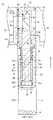
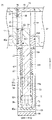
도 1은 본 발명의 일 실시예에 따른 게이트 밸브의 단면을 부분적으로 나타낸 정면도;
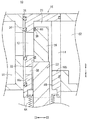
도 2는 도 1의 II-II 선을 따라 취해진 단면도;
도 3은 도 2의 밸브 디스크 부근을 나타내는 확대 단면도;
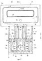
도 4는 도 1의 IV-IV 선을 따라 취해진 단면도;
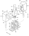
도 5는 도 1의 상기 게이트 밸브에서 구동 절환 유닛의 분해 사시도;
도 6은 도 1의 상기 게이트 밸브에서 밸브 디스크가 이동되는 밸브 열림 상태를 도시하고, 단면을 부분적으로 나타낸 정면도;
도 7은 도 6의 VII-VII 선을 따라 취해진 단면도; 및
도 8은 상기 밸브 시트를 향하여 대면하는 상기 밸브 디스크에 있는 위치에 대하여 도 7에 도시된 상기 게이트 밸브의 상기 밸브 열림 상태로부터 상기 밸브 디스크가 이동되는 상태를 나타낸 단면도.1 is a front view partially showing a cross section of a gate valve according to an embodiment of the present invention;
FIG. 2 is a sectional view taken along line II-II in FIG. 1; FIG.
FIG. 3 is an enlarged sectional view showing the vicinity of the valve disk of FIG. 2; FIG.
FIG. 4 is a sectional view taken along the line IV-IV in FIG. 1; FIG.
5 is an exploded perspective view of the drive switching unit in the gate valve of Fig. 1;
Fig. 6 is a front view partially showing a valve opening state in which the valve disc is moved in the gate valve of Fig. 1; Fig.
7 is a cross-sectional view taken along line VII-VII of FIG. 6; And
8 is a cross-sectional view showing a state in which the valve disc is moved from the valve-opened state of the gate valve shown in Fig. 7 to a position on the valve disc facing the valve seat;
도 1 및 도 2와 같이, 게이트 밸브(10)는 도시되지 않은 워크피스(예를 들면, 반도체 웨이퍼)가 삽입되고 분리되는 것을 허용하도록 제1, 2 통로(12, 14, 도 2 참조)가 형성된 밸브 박스(16)와, 상기 밸브 박스(16)의 하부에 연결되는 하우징(18)과, 구동 유닛으로 기능하며 상기 하우징(18)의 내부에 배치되는 실린더부(20)와, 상기 실린더부(20)의 구동 작용하에서 축 방향(화살표 A, B 방향)을 따라 변위됨은 물론, 상기 축 방향에 대하여 실질적으로 수직하게 움직이는 밸브 로드(22)와, 상기 밸브 박스(16)의 제1 통로(12)를 닫을 수 있고 상기 밸브 로드(22)의 일단부와 연결되는 밸브 디스크(24)와, 상기 밸브 로드(22)의 축에 대하여 직교 방향으로 이동하는 상기 실린더부(20)의 직선 변위를 절환하는 구동 절환 유닛(26)을 포함한다.1 and 2, the
도 2 및 도 3과 같이, 상기 밸브 박스(16)는, 예를 들면, 중공의 박스와 같은 형상으로 형성되며, 상기 밸브 디스크(24)가 이동 가능하도록 그 내부가 제공되는 수용 룸(28)을 포함한다. 상기 수용 룸(28)을 향하여 대면하는 상기 밸브 박스(16)의 일측 벽(16a, 벽 부) 및 타측 벽(16b)상에서, 상기 제1, 2 통로(12, 14)가 단면에서 보아 사각 형상으로 각각 개방되도록 형성된다.2 and 3, the
상기 밸브 박스(16)에서, 상기 일측 벽(16a)의 내부 벽면 상에서, 밸브 시트(20)가 상기 제1 통로(12)를 향하여 대면하도록 형성된다. 상기 밸브 시트(30)는 상기 밸브 디스크(24)가 접할 수 있도록 배치된다. 상기 밸브 박스(16)에 있어서 상기 일측 벽(16a)과 상기 타측 벽(16b)은 상기 수용 룸(28)을 사이에 두고 실질적으로 평행하게 형성된다(도 2 참조).In the
또한, 상기 밸브 박스(16)에 있어서, 처리 챔버(S1)는, 다른 처리 챔버(S2)가 타측 벽(16b)의 측면과 연결되고 상기 제2 통로(14)를 통하여 연통되는 동안, 상기 일측 벽(16a)의 측면과 연결되고 상기 제1 통로(12)를 통하여 연통된다.In the
또한, 도 1 내지 도 3과 같이, 밸런스 룸(32)은 상기 처리 챔버(S1)를 향하여 대면하는 외측 벽면 상에 소정 깊이로 함몰되며, 상기 밸브 박스(16)의 상기 일측 벽(16a) 상에 형성된다. 상기 밸런스 룸(32)은 상기 일측 벽(16a)의 외측 가장자리에 대하여 소정 폭을 가지고 내측을 형성되고, 상기 제1 통로(12)는 상기 밸런스 룸(32)의 중심부에 있어서 개방된다. 더욱 구체적으로는, 상기 밸런스 룸(32)은 상기 밸런스 룸(32)의 중심부에 있어서 상기 제1 통로(12)를 가지는 링 형상으로 형성된다.1 to 3, the
또한, 상기 밸런스 룸(32)은 상기 제1 통로(12)의 외측면을 덮도록 배치되는 제1 씰 부재(34, 씰 부재)를 포함하며, 제2 씰 부재(36)는 상기 밸런스 룸(32)의 외측 가장자리에 배치된다. 상기 제1, 2 씰 부재(34, 36)는, 예를 들면, 고무 등과 같은 탄성 재질로 이루어진 실질적으로 사각 링 형상으로 형성되고, 상기 밸런스 룸(32)의 상기 벽 부에 형성되는 각각의 링 형상 홈에 장착된다. 상기 제1, 2 씰 부재(34, 36)가 상기 링 형상 홈에 각각 장착된 상태에 있어서, 상기 제1, 2 씰 부재(34, 36)는 상기 처리 챔버(S1)의 측면을 향하여 상기 외측 벽면으로부터 소정 높이로 돌출되도록 배치된다(도 3 참조).The
바꿔 말하면, 상기 밸런스 룸(32)은 상기 제2 씰 부재(36)가 상기 제1 씰 부재(34)의 외측을 둘러싸도록 상기 제1 씰 부재(34)가 그 내부에 배치되는 링 형상으로 형성된다.In other words, the
본 발명은 상기 제2 씰 부재(36)가 상기 제1 씰 부재(34)의 외측 둘레에 배치되는 경우에 국한되지 않으며 상기 밸런스 룸(32)은 상기 제1 씰 부재(34)와 상기 제2 씰 부재(36) 사이에 형성된다. 예를 들면, 상기 밸런스 룸(32)은 후술할 밸런스 포트(38)를 에워싸도록 상기 제1 씰 부재(34)로부터 하측으로 배치될 수도 있다.The present invention is not limited to the case where the
또한, 상기 밸런스 포트(38, 연통 포트)는 상기 제1 씰 부재(34)와 상기 제2 씰 부재(36) 사이의 위치에서 상기 밸런스 룸(32) 내에 형성된다. 상기 밸런스 포트(38)는, 예를 들면, 단면에서 보아 실질적으로 원형이며, 상기 수용 룸(28)에 대하여 상기 밸런스 룸(32)으로부터 직선으로 관통된다. 더욱 구체적으로는, 상기 밸런스 포트(38)는 그것으로부터 소정 거리 이격되는 동안 상기 제1 통로(12)와 실질적으로 평행하게 형성되며, 상기 제1 통로(12)보다 단면적이 작게 형성된다.The
도 1 및 도 2와 같이, 상기 하우징(18)은 상기 밸브 박스(16)의 하단부와 연결되는 베이스 프레임(40)과, 상기 베이스 프레임(40)의 양단부에 대하여 각각 연결되고 그 사이에 상기 실린더부(20)를 지지하는 한 쌍의 측면 프레임(42a, 42b)과, 상기 측면 프레임(42a, 42b)의 하단부 각각과 결합되거나 상호 연결되는 커버 프레임(44)으로 이루어진다.1 and 2, the
상기 베이스 프레임(40)은 상기 밸브 박스(16)의 하부를 덮도록 배치된다. 상기 밸브 박스(16)의 상기 수용 룸(28)과 상기 하우징(18)의 내부는 상기 베이스 프레임(40)의 중앙에 실질적으로 형성된 로드 홀(46)을 통하여 상호 연통한다. 후술할 밸브 로드(22)는 상기 로드 홀(46)을 통하여 변위 가능하게 삽입된다.The
상기 측면 프레임(42a, 42b)은 상기 베이스 프레임(40)에 대하여 실질적으로 직교되게 형성된다. 상기 베이스 프레임(40)은 상기 측면 프레임(42a, 42b)의 상단부와 연결되고, 상기 실린더부(20)를 구성하는 실린더 튜브(50)들은, 실질적으로 평행 상태에서 상기 측면 프레임(42a, 42b) 양자에 각각 고정된다.The
도 1과 같이, 상기 실린더부(20)는 상기 베이스 프레임(40)의 길이 방향을 따라 양단부에 배치되는 한 쌍의 유체압 실린더(48a, 48b)로 구성된다. 상기 각 유체압 실린더(48a, 48b)는, 각각, 상기 중공의 원통 형상인 실린더 튜브(50)와, 상기 실린더 튜브(50)의 내부에서 축 방향(화살표 A, B 방향)을 따라 변위하기 위하여 배치되는 피스톤(52)과, 상기 피스톤(52)과 연결되는 피스톤 로드(54)를 포함한다.1, the
상기 실린더 튜브(50)들의 일단부는, 타단부가 로드 커버(56)에 의하여 상기 피스톤 로드(54)가 삽입될 수 있도록 닫히는 반면, 상기 베이스 프레임(40)에 대하여 연결됨으로써 닫혀진다. 따라서, 상기 실린더 튜브(50)의 내부에 대하여 도시하지 않은 포트로부터 공급되는 압력 유체에 의하여, 상기 피스톤(52)은 축 방향(화살표 A, B 방향)으로 눌려짐으로써, 상기 피스톤 로드(54)를 변위시킨다.One end of the
또한, 도 2, 도 4 및 도 5와 같이, 상기 게이트 밸브(10)의 중앙측에 상기 실린더 튜브(50) 각각의 측면에 있어서, 한 쌍의 가이드 롤러(58a, 58b)가 회전 가능하게 배치된다. 상기 가이드 롤러(58a, 58b)와 함께, 함몰된 홈(60)들이 상기 가이드 롤러(58a, 58b)로부터 소정 거리만큼 이격되고 실질적으로 평행하게 형성된다.As shown in Figs. 2, 4 and 5, a pair of
상기 가이드 롤러(58a, 58b)는 상기 실린더 튜브(50)의 축 방향(화살표 A, B 방향)을 따라 소정 거리 이격되며, 일직선상에 배치된다.The
한편, 도 2 및 도 5와 같이, 수평홈부(62)가 상기 함몰된 홈(60)의 각각의 상단에 형성된다. 상기 수평홈부(62)는 상기 함몰된 홈(60)이 연장되는 방향에 대하여 실질적으로 직교되는 방향에 있어서, 상기 밸브 박스(16)의 상기 밸브 시트(30)측을 향하여 연장된다. 상기 구동 절환 유닛(26)을 구성하는 스토퍼 롤러(84)는, 상기 함몰된 홈(60)에 삽입된다.On the other hand, as shown in Figs. 2 and 5, the
상기 피스톤 로드(54)의 상단부는, 상기 피스톤 로드(54)의 하단부가 상기 실린더 튜브(50)로부터 외측으로 돌출되고 후술할 요크(68, yoke)에 대하여 각각 연결되는 반면, 상기 피스톤(52)의 중앙부와 연결된다.The lower end of the
상기 밸브 로드(22)는 상기 하우징(18)의 중심에 실질적으로 배치되며, 상기 베이스 프레임(40)의 상기 로드 홀(46)을 통하여 삽입된다. 실질적으로 그 축 방향에 따른 상기 밸브 로드(22)의 중심부는 벨로우즈(64)에 의하여 커버된다. 상기 벨로우즈(64)는, 상기 밸브 로드(22)가 축 방향(화살표 A, B 방향)으로 변위되도록, 주름관 형상인 원통형 몸체로 이루어지며, 상기 벨로우즈(64)는 상기 밸브 로드(22)의 일부가 항상 커버되도록, 상기 밸브 로드(22)를 커버하는 동안 신장 및 수축한다. 또한, 상기 밸브 로드(22)의 상단은 상기 밸브 박스(16)의 내부에 삽입되고 상기 밸브 디스크(24)와 연결된다.The
상기 밸브 디스크(24)는 상기 밸브 박스(16)에서 상기 제1 통로(12)의 개방부에 대응되는 단면이 사각 형상을 가진 플레이트로 구성된다. 상기 밸브 로드(22)는 상기 밸브 디스크(24)의 중심부와 실질적으로 연결되며, 씰링 링(66, 도 2 및 도 3 참조)은 상기 밸브 시트(30)를 향하여 대면하는 상기 밸브 디스크(24)의 측면에서 링 형상 홈을 통하여 장착된다. 그리고, 상기 밸브 디스크(24)가 상기 밸브 시트(30)에 안착된 밸브 닫힘 상태에 있어서, 상기 씰링 링(66)은 상기 제1 통로(12)의 연통 상태를 차단함으로써 상기 밸브 시트(30)에 대하여 접한다.The
도 1 내지 도 5와 같이 상기 구동 절환 유닛(26)은 상기 피스톤 로드(54)의 타단부에 고정되는 상기 요크(68)와, 상기 요크(68)와 일체로 변위되는 변위 블록(70)을 포함한다.1 to 5, the
상기 요크(68)는, 예를 들면, 상기 피스톤 로드(54)의 축들에 대하여 직교되게 배치되는 베이스부(72)와, 상기 베이스부(72)에 대하여 직교되게 세워지는 방법으로 세워진 두 개의 캠 프레임(74)으로 이루어진다. 상기 한 쌍의 유체압 실린더(48a, 48b)의 상기 피스톤 로드(54)는 각각 상기 베이스부(72)의 반대 단부와 연결된다. 따라서, 상기 요크(68)는, 상기 피스톤 로드(54)가 상기 실린더 튜브(50)에 대한 압력 유체의 공급 하에 상기 피스톤(52)과 함께 변위될 때 일체적으로 변위된다.The
도 4 및 도 5와 같이, 상기 캠 프레임(74) 각각은 길이 방향으로 연장된 가이드 홈(76)과, 상기 가이드 홈(76)과 실질적으로 평행하게 형성된 한 쌍의 캠 홈(78a, 78b)을 포함하며, 상기 길이 방향을 따라 소정 거리만큼 상호 이격된다. 상기 캠 홈(78a, 78b)은 상기 캠 홈(78a, 78b)의 상단부가 상기 밸브 시트(30)로부터 이격하는 방향으로 지향하도록 경사지게 형성된다.4 and 5, each of the cam frames 74 includes a
상기 밸브 로드(22)는 상기 변위 블록(70)의 중앙부에 대하여 실질적으로 일체로 삽입되고 연결된다. 스프링(80)은, 예를 들면, 상기 요크(68)와 상기 변위 블록(70)의 하단 사이에 배치되는 코일 스프링으로 구성된다. 상기 스프링(80)의 탄성력은, 상기 요크(68)와 상기 변위 블록(70)이 상호 이격되도록 하는 방향(화살표 A, B 방향)으로 상기 요크(68)와 상기 변위 블록(70)을 밀어 붙인다. The
또한, 두 쌍의 캠 롤러(82a, 82b)는 상기 변위 블록(70)의 대향 측면으로부터 외측으로 돌출되는 동안 회전 가능하게 배치되고 지지된다. 그리고, 상기 캠 롤러(82a, 82b)는 각각 상기 요크(68)의 상기 캠 홈(78a, 78b)에 삽입된다. 이와 함께, 상기 베이스부(72)로부터 더 이격되는 상기 캠 롤러(82a)와 동축적으로 배치되는 상기 스토퍼 롤러(84)는, 상기 실린더 튜브(50)의 상기 함몰된 홈(60)에 상기 캠 홈(78a)을 통하여 삽입된다. 상기 스토퍼 롤러(84)는 상기 캠 롤러(82a)보다 작은 직경으로 형성된다.In addition, the pair of
또한, 상기 변위 블록(70)이 상기 실린더부(20)의 구동에 의하여 상기 요크(68)와 함께 상승되면, 상기 요크(68)는 상기 가이드 홈(76)에 삽입되는 상기 실린더 튜브(50)의 상기 가이드 롤러(58a, 58b)에 의하여 이루어진 가이드 동작 하에 수직 방향(화살표 B 방향)으로 이동된다. 그리고, 상기 스토퍼 롤러(84)는 상기 함몰된 홈(60)의 상단에서 상기 수평 홈부(62)로 이동함으로써, 상기 스토퍼 롤러(84)는 수평적으로 움직인다. 그 결과, 상기 변위 블록(70)의 통작을 통하여, 상기 밸브 로드(22) 및 상기 밸브 디스크(24)는 상기 밸브 시트(30)의 측면을 향하여 수평적으로 움직인다(도 2 및 도 3에서 화살표 C1 방향).When the
본 발명의 실시 형태에 따른 상기 게이트 밸브(10)는 기본적으로 위에서 서술한 바와 같이 구성된다. 다음으로, 상기 게이트 밸브(10)의 동작 및 장점들이 설명될 것이다. 다음의 설명에서, 도 6에 도시된 상태와 같이, 상기 실린더부(20)를 구성하는 두(한 쌍의) 피스톤(52)이 하측(화살표 A 방향)으로 이동되고, 도 6 및 도 7과 같이, 상기 밸브 디스크(24)가 상기 밸브 박스(16)의 내부에서 하측으로 변위됨으로써, 상기 제1 통로(12)와 상기 제2 통로(14) 사이의 연통이 가능하게 하는 것(밸브 열림 상태)이, 초기 상태로서 설명될 것이다.The
우선, 상기 초기 상태에 있어서, 도시되지 않은 압력 유체 공급원으로부터 일측 포트에 대한 압력 유체의 공급에 의하여, 상기 피스톤(52)은 상기 실린더 튜브(50)의 내부로 공급되는 상기 압력 유체에 의하여 상측(화살표 B 방향)으로 눌려지고 변위된다.First, in the initial state, by the supply of the pressure fluid from the pressure fluid supply source (not shown) to the one port, the
상기 피스톤(52)의 변위에 동반하여, 상기 요크(68)와 상기 변위 블록(70)은 일체적으로 상승하고, 상기 밸브 로드(22) 및 상기 밸브 디스크(24) 또한 이에 따라 상승한다. 이때, 상기 가이드 홈(76)은 상기 실린더부(20)의 상기 가이드 롤러(58a, 58b)와 결합되어 있기 때문에, 상기 요크(68)는 상측 방향으로 직교되게 안내되고, 상기 한 쌍의 캠 롤러(82a, 82b)는 상기 캠 홈(78a, 78b)의 상단부와 맞닿아 접한 상태로 유지되는 동안 각각 이동한다.In conjunction with the displacement of the
그리고, 상기 변위 블록(70)의 상기 스토퍼 롤러(84)는 상기 함몰된 홈(60)의 상단에 대하여 이동하고, 그 최종 위치에 도착함으로써, 더 이상의 상승은 규제되고, 도 8과 같이, 상기 밸브 디스크(24)는 상기 제1 통로(12)와 상기 밸브 박스(16) 내부의 상기 밸브 시트(30)에 대하여 대면하도록 위치된다. 이 경우, 상기 스프링(80)의 탄성력은 상기 요크(68)로부터 누르는 힘보다 크기 때문에, 상기 스프링(80)은 상기 요크(68)에 의하여 압축되지 않으며, 상기 요크(68) 및 상기 변위 블록(70)은 상호 상대적으로 변위하는 일이 없이 일제히 변위된다.8, the
이때, 상기 밸브 디스크(24)는 상기 밸브 시트(30)에 안착되지 않았으므로, 밸브 닫힘 상태는 아직 일어나지 않았으며, 상기 밸브 박스(16)의 상기 제1 통로(12)와 상기 제2 통로(14) 약간의 틈을 통하여 연통 상태를 유지한다.At this time, since the
상기 밸브 디스크(24)가 상기 밸브 시트(30)에 대하여 대면하도록 위치된 도 8의 상태로부터, 상기 압력 유체는 상기 실린더 튜브(50)로 더욱 계속 유입된다. 따라서, 상기 피스톤(52)의 추가적인 상승에 따라, 상기 요크(68)는 상기 피스톤 로드(54)에 의하여 상측(화살표 B 방향)으로 당겨진다. 이때, 상기 변위 블록(70)의 상기 스토퍼 롤러(84)는 움직임이 없이 상기 함몰된 홈(60)의 상단부에 의하여 맞물려 있으므로, 상기 스프링(80)이 눌려지는 동안 오로지 상기 요크(68)만이 상측으로 변위된다. 바꿔 말하면, 상기 요크(68)는 상기 변위 블록(70)에 대하여 상대적으로 변위된다.From the state of FIG. 8 in which the
그리고, 상기 요크(68)의 상승에 동반하여, 상기 스토퍼 롤러(84)는 상기 함몰된 홈(60)의 상기 수평 홈부(62)로 이동함으로써, 상기 변위 블록(70)은 상기 밸브 시트(30)측으로 접근하도록, 축선과 직교하는 방향(화살표 C1 방향), 즉, 수평적으로 이동하고, 상기 변위 블록(70)에 지지된 상기 밸브 로드(22)와, 밸브 디스크(24)가 일체적으로 수평 방향으로 이동한다. 따라서, 도 2 및 도 3과 같이, 상기 밸브 디스크(24)가 상기 밸브 시트(30)에 상기 씰 링(66)을 밀어 누르면서 안착되고, 상기 밸브 박스(16)의 상기 제1 통로(12)가 닫히는 밸브 닫힘 상태가 야기된다.The
따라서, 상기 제1 통로(12)가 닫히는 상기 일측 처리 챔버(S1)에 있어서, 처리 단계는 반도체 웨이퍼 등과 같은 워크피스에 실시될 수 있다.Therefore, in the one-side processing chamber S1 in which the
다음으로, 밸브 열림 상태의 경우에서, 상기 밸브 디스크(24)가 상기 밸브 시트(30)로부터 이격됨에 있어서, 그리고 상기 제1 통로(12) 및 상기 제2 통로(14)가 다시 상기 수용 룸(28)을 통하여 연통되게 놓여지고, 도시되지 않은 절환 수단의 절환 동작 하에서, 압력 유체는 상기 실린더부(20)의 상기 실린더 튜브(50)의 내부에 대하여 다른 포트로부터 공급된다. 이에 따라, 상기 피스톤(52)은 하강하며, 상기 피스톤 로드(54)는 상기 피스톤(52)과, 상기 피스톤(52)과 일체적으로 하강되는 상기 요크(68)와 연결된다. 따라서, 상기 스프링(80)이 신장되는 상태가 야기되며, 상기 스토퍼 롤러(84)는 상기 수평 홈부(62)로부터 이격되게 움직이며, 상기 캠 롤러(82a, 82b)는 상기 캠 홈(78a, 68b)의 상단부에 대하여 각각 접한다. 이러한 동작들과 동반하여, 상기 밸브 디스크(24)는 상기 밸브 시트(30)로부터 이격하는 방향(화살표 C2 방향)으로 상기 밸브 로드(22)와 함께 수평적으로 이동하며, 상기 밸브 시트(30)로부터 상기 밸브 디스크(24)를 분리함으로써, 상기 제1 통로(12)의 차단된 상태는 해제된다.Next, in the case of the valve open state, the
그리고, 상기 실린더 튜브(50)로 상기 압력 유체가 더 도입되고 상기 피스톤(52)이 하강함으로써, 상기 변위 블록(70), 상기 밸브 로드(22), 및 상기 밸브 디스크(24)는 상기 피스톤 로드(54)와 함께 하강되며, 상기 초기 상태, 이른바, 상기 밸브 열림 상태는 상기 밸브 박스(15) 내의 상기 제1 통로(12)를 향하여 대면하는 위치로부터 멀어지게 하강하고 이동하는 상기 밸브 디스크(24)에 의하여 복귀된다(도 6 및 도 7 참조).The
따라서, 상기 밸브 박스(16) 내에서 상기 제1 통로(12)와 상기 제2 통로(14)가 상호 연통하는 상태가 야기되고, 도시되지 않은 반도체 웨이퍼 등과 같은 상기 워크피스는 상기 제1 통로(12)를 통하여 이동될 수 있다. 따라서, 예를 들면, 상기 제1 처리 챔버(S1) 내에서 행해지는 처리 단계에서 워크피스는, 상기 제1 통로(12)로부터 상기 수용 룸(28)과 상기 제2 통로(14)를 통하여 이동되고, 상기 워크피스 상에 다른 처리 단계가 실시될 수 있는 상기 처리 챔버(S2)로 이동된다.This causes the
또한, 상기 워크피스가 전술한 상기 다른 처리 챔버(S2)로 이동된 밸브 닫힘 상태에 있어서, 그리고 밸브 디스크(24)가 다시 상기 밸브 시트(30)에 안착되며, 상기 밸브 박스(16)의 후면측과 연결된 상기 다른 처리 챔버(S2)가 진공압을 유지하는 반면, 상기 일측의 처리 챔버(S1)가 대기압을 유지하는 상황이 일어날 수 있다. 이러한 상태에서, 상기 밸브 박스(16)의 상기 수용 룸(28)은 상기 제2 통로(14)를 통하여 상기 제2 처리 챔버(S2)와 연통하고 있으므로, 상기 수용 룸(28)의 내부는 또한 같은 진공압을 유지하며, 상기 하나의 처리 챔버(S1)와 상기 수용 룸(28) 사이의 상기 밸브 디스크(24)에 걸쳐 압력차가 발생한다.In the valve closed state in which the workpiece is moved to the above-mentioned another processing chamber S2 and the
본 발명에 의하여, 상기 수용 룸(28)과 상기 밸런스 룸(32)의 내부가 상기 밸런스 포트(38)를 통하여 연통되게 놓여있기 때문에, 상기 밸런스 룸(32) 내부의 상기 진공압은 상기 수용 룸(28)과 같이 만들어질 수 있거나, 혹은 달리 말해, 상기 밸런스 룸(32)과 상기 수용 룸(28) 내의 각각의 압력은 같아질 수 있다. 그러므로, 상기 밸브 박스(16) 내에서, 상기 외부 벽면과 상기 일측 벽(16a)의 내부 벽면에 걸리는 상기 압력은, 상기 밸브 박스(16)의 상기 일측 벽(16a)에 맞닿아 접하는 상기 하나의 처리 챔버(S1)가 대기압을 유지하는 반면, 상기 밸브 박스(16)의 상기 수용 룸(28)이 진공압 하에 놓여있더라도, 같아지며, 압력차에 의하여 야기되는 부하들은 상기 일측 벽(16a)의 내, 외측에 걸리지 않게 된다.According to the present invention, since the inside of the
그 결과, 상기 밸브 박스(16)에 있어서 일측 벽(16a)의 변형이 방지될 수 있다. 이와 함께, 상기 밸브 디스크(24)가 상기 밸브 시트(30) 상에 안착되는 밸브 닫힘 상태에 있더라도, 상기 일측 벽(16a)에 형성된 상기 밸브 시트(20)의 변형이 회피되며, 상기 밸브 디스크(24)와 상기 밸브 시트(30) 사이에 일어나는 이와 같은 변형으로 인하여 틈도 생기지 않으므로, 상기 제1 통로(12)와의 연통 상태는 상기 밸브 디스크(24)에 의하여 확실하고 안정적으로 차단될 수 있다.As a result, deformation of one
전술한 수단에 있어서, 본 발명의 실시 형태에 따르면, 상기 하나의 처리 챔버(S1)를 향하여 대면하는 상기 밸브 박스(16)의 상기 일측 벽(16a)에 소정 깊이로 함몰된 상기 밸런스 룸(32)과, 상기 밸런스 룸(32)과 상기 수용 룸(28) 사이로 연통하는 상기 밸런스 포트(38)가 제공된다. 또한, 이러한 구조에 있어서, 상기 밸런스 룸(32) 내의 상기 제1 통로(12)의 외측은 상기 제1 씰 부재(34)에 의하여 둘러싸이게 되며, 상기 밸런스 룸(32)의 외측 가장자리는 상기 제2 씰 부재(36)에 의하여 둘러싸이게 된다.According to the above-described means, according to the embodiment of the present invention, the one
따라서, 상기 밸브 디스크(24)가 상기 밸브 시트(30)에 안착된 밸브 닫힘 상태에 있어서, 상기 수용 룸(28)과 상기 하나의 처리 챔버(S1) 사이에서 압력차가 발생되더라도, 상기 밸런스 포트(38)를 통하여 상기 수용 룸(28)과 상기 밸런스 룸(32) 사이의 연통이 가능함으로써, 상기 밸브 박스(16)의 상기 일측 벽(16a)의 내, 외측에 걸리는 상기 압력은 같은 압력으로 설정되거나 같아지게 된다.Even if a pressure difference is generated between the
그 결과, 상기 밸브 박스(16)의 하중을 증대시키는 일이 없이, 압력 차에 기인하는 상기 밸브 박스(16)에 있어서 상기 일측 벽(16a)의 변형이 확실하게 방지될 수 있다. 또한, 상기 일측 벽(16a)에 형성된 상기 밸브 시트(30)의 변형이 일어나지 않으므로, 평판 형상으로 형성된 상기 밸브 디스크(24)는, 상기 밸브 시트(30) 상에 확실하고 안정적으로 안착될 수 있으며, 상기 밸브 디스크(24)의 씰링이 확보될 수 있다.As a result, the deformation of the one
또한, 상기 밸런스 룸(32) 내에서, 상기 제1 통로(12)와의 연통은 상기 제1 씰 부재(34)에 의하여 차단되므로, 상기 밸런스 룸(32)을 상기 제1 통로(12)와의 연통 외부에 유지시킴으로써, 상기 밸런스 룸(32)을 통한 상기 일측의 처리 챔버(S1)와 상기 수용 룸(28) 사이의 연통과, 상기 일측의 처리 챔버(S1)와 상기 수용 룸(28) 사이의 압력이 같아지는 것들이, 방지된다.Since the communication with the
본 발명에 따른 상기 게이트 밸브는 위에서 서술된 실시 형태에 한정되지 않으며, 다양한 변형 또는 추가적인 구조들이 본 발명의 청구 범위에서 설정된 본 발명의 기술 범위로부터 벗어나는 일이 없이 채용될 수 있다.
The gate valve according to the present invention is not limited to the embodiment described above, and various modifications or additional structures may be employed without departing from the scope of the present invention set forth in the claims of the present invention.
Claims (4)
상기 밸브 박스(16)는,
상기 밸브 디스크(24)가 수용되는 수용 룸(28);
상기 밸브 디스크(24)가 안착되는 밸브 시트(30)를 포함하며 상기 수용 룸(28)의 일부를 구성하는 벽 부(16a);
상기 밸브 박스(16)에 접하는 처리 챔버(S1)와 상기 수용 룸(28) 사이의 연통을 제공하고 상기 벽 부(16a)에 형성되는 통로(12);
상기 처리 챔버(S1)에 대하여 대면함에 있어서 상기 벽 부(16a)에 형성되는 밸런스 룸(32); 및
상기 밸런스 룸(32)과 상기 수용 룸(28) 사이의 연통을 제공하고, 상기 밸런스 룸(32)의 내부에서 상기 통로(12)와 연통되는 외측에 배치되는 연통 포트(38)를 포함하는 게이트 밸브.
A valve disc (24) configured to be seated against a valve seat (30) formed in the valve box (16) and a valve disc (24) configured to be seated against the valve seat A valve rod 22 connected to the valve disc 24 and linearly displacing the valve rod 22 along an axial direction of the valve rod 22, (10) having a drive unit (20) disposed inside a cylinder (18)
The valve box (16)
A receiving chamber (28) in which the valve disc (24) is received;
A wall portion (16a) including a valve seat (30) on which the valve disc (24) is seated and constituting a part of the receiving chamber (28);
A passage (12) formed in the wall portion (16a) to provide communication between the processing chamber (S1) in contact with the valve box (16) and the receiving chamber (28);
A balance chamber (32) formed on the wall portion (16a) facing the processing chamber (S1); And
And a communication port (38) providing communication between the balance chamber (32) and the receptacle room (28) and disposed outside the balance chamber (32) valve.
상기 통로(12)는 상기 밸런스 룸(32)의 중심부에서 개방되고, 씰 부재(34)는 상기 통로(12)와 상기 밸런스 룸(32) 사이에 배치되며, 상기 통로(12) 및 상기 밸런스 룸(32)은 상기 씰 부재(34)에 의하여 분리되는 게이트 밸브.
The method according to claim 1,
The passage 12 is open at the center of the balance chamber 32 and the seal member 34 is disposed between the passage 12 and the balance chamber 32, (32) is separated by the seal member (34).
상기 통로(12) 및 상기 연통 포트(38)는 실질적으로 평행하게 형성되는 게이트 밸브.
The method according to claim 1,
Wherein the passage (12) and the communication port (38) are formed substantially parallel.
상기 연통 포트(38)는 상기 통로(12)보다 작은 단면적으로 형성되는 게이트 밸브.
The method of claim 3,
Wherein the communication port (38) is formed to have a smaller cross sectional area than the passage (12).
Applications Claiming Priority (2)
| Application Number | Priority Date | Filing Date | Title |
|---|---|---|---|
| JP2014093750A JP6160923B2 (en) | 2014-04-30 | 2014-04-30 | Gate valve |
| JPJP-P-2014-093750 | 2014-04-30 |
Related Child Applications (1)
| Application Number | Title | Priority Date | Filing Date |
|---|---|---|---|
| KR1020170069469A Division KR101814045B1 (en) | 2014-04-30 | 2017-06-05 | Gate valve |
Publications (1)
| Publication Number | Publication Date |
|---|---|
| KR20150125610A true KR20150125610A (en) | 2015-11-09 |
Family
ID=54326134
Family Applications (2)
| Application Number | Title | Priority Date | Filing Date |
|---|---|---|---|
| KR1020150061306A KR20150125610A (en) | 2014-04-30 | 2015-04-30 | Gate valve |
| KR1020170069469A KR101814045B1 (en) | 2014-04-30 | 2017-06-05 | Gate valve |
Family Applications After (1)
| Application Number | Title | Priority Date | Filing Date |
|---|---|---|---|
| KR1020170069469A KR101814045B1 (en) | 2014-04-30 | 2017-06-05 | Gate valve |
Country Status (7)
| Country | Link |
|---|---|
| US (1) | US9599233B2 (en) |
| JP (1) | JP6160923B2 (en) |
| KR (2) | KR20150125610A (en) |
| CN (1) | CN105020423B (en) |
| CH (1) | CH709581B8 (en) |
| DE (1) | DE102015105899B4 (en) |
| TW (1) | TWI580880B (en) |
Families Citing this family (14)
| Publication number | Priority date | Publication date | Assignee | Title |
|---|---|---|---|---|
| CN107110402B (en) * | 2014-12-19 | 2019-10-25 | Vat控股公司 | Closed door is carried out for the room opening in the locular wall to vacuum chamber |
| JP6356645B2 (en) * | 2015-09-04 | 2018-07-11 | 株式会社鷺宮製作所 | Throttle device and refrigeration cycle |
| JP6774302B2 (en) * | 2016-10-28 | 2020-10-21 | 株式会社キッツエスシーティー | Vacuum gate valve |
| KR102145830B1 (en) * | 2017-10-13 | 2020-08-19 | 주식회사 라온티엠디 | A valve complex |
| CN107940096B (en) * | 2018-01-12 | 2023-11-21 | 眉山中车制动科技股份有限公司 | Bidirectional mechanism |
| CN110242758B (en) * | 2018-03-09 | 2021-02-26 | (株)Np控股 | Sealing member replacement type gate valve system, sealing plate, and cartridge for sealing plate |
| WO2019239673A1 (en) * | 2018-06-12 | 2019-12-19 | 株式会社アルバック | Gate valve device |
| DE102019001115A1 (en) * | 2019-02-15 | 2020-08-20 | Vat Holding Ag | Gate valve with link guide |
| JP6745953B1 (en) * | 2019-07-23 | 2020-08-26 | 株式会社アルバック | Partition valve |
| DE102019123563A1 (en) * | 2019-09-03 | 2021-03-04 | Vat Holding Ag | Vacuum valve for loading and / or unloading a vacuum chamber |
| CN110993550B (en) * | 2019-12-25 | 2022-12-09 | 北京北方华创微电子装备有限公司 | Semiconductor heat treatment equipment |
| JP2021134893A (en) * | 2020-02-28 | 2021-09-13 | Smc株式会社 | Gate valve |
| KR20220120613A (en) * | 2020-06-10 | 2022-08-30 | 엘지전자 주식회사 | Gate valve module and hermetic chamber |
| JP2022144982A (en) * | 2021-03-19 | 2022-10-03 | Smc株式会社 | Gate valve with shaking prevention mechanism |
Family Cites Families (11)
| Publication number | Priority date | Publication date | Assignee | Title |
|---|---|---|---|---|
| US2660397A (en) | 1951-08-27 | 1953-11-24 | Alexander S Volpin | Quick sealing automatic sealing gate valve |
| US2971527A (en) | 1955-08-29 | 1961-02-14 | Mcevoy Co | Automatic plastic sealed valves |
| JPH05196150A (en) * | 1991-09-30 | 1993-08-06 | Tokyo Electron Yamanashi Kk | Gate valve |
| JPH05272662A (en) * | 1992-03-25 | 1993-10-19 | Fujitsu Ltd | Gate valve |
| JPH11351419A (en) | 1998-06-08 | 1999-12-24 | Irie Koken Kk | Non-slide gate valve |
| US6095741A (en) * | 1999-03-29 | 2000-08-01 | Lam Research Corporation | Dual sided slot valve and method for implementing the same |
| JP2001330172A (en) * | 2000-05-22 | 2001-11-30 | Nec Kansai Ltd | Gate valve |
| US6602346B1 (en) | 2000-08-22 | 2003-08-05 | Novellus Systems, Inc. | Gas-purged vacuum valve |
| JP5005512B2 (en) * | 2007-11-07 | 2012-08-22 | 東京エレクトロン株式会社 | A gate valve device, a vacuum processing device, and a method for opening a valve body in the gate valve device. |
| JP5545152B2 (en) * | 2010-09-22 | 2014-07-09 | Smc株式会社 | Gate valve |
| JP5806827B2 (en) * | 2011-03-18 | 2015-11-10 | 東京エレクトロン株式会社 | Gate valve apparatus, substrate processing apparatus and substrate processing method thereof |
-
2014
- 2014-04-30 JP JP2014093750A patent/JP6160923B2/en active Active
-
2015
- 2015-04-06 US US14/679,227 patent/US9599233B2/en not_active Expired - Fee Related
- 2015-04-16 TW TW104112183A patent/TWI580880B/en active
- 2015-04-17 DE DE102015105899.5A patent/DE102015105899B4/en active Active
- 2015-04-23 CH CH00555/15A patent/CH709581B8/en unknown
- 2015-04-29 CN CN201510215805.2A patent/CN105020423B/en active Active
- 2015-04-30 KR KR1020150061306A patent/KR20150125610A/en active Application Filing
-
2017
- 2017-06-05 KR KR1020170069469A patent/KR101814045B1/en active IP Right Grant
Also Published As
| Publication number | Publication date |
|---|---|
| DE102015105899A1 (en) | 2015-11-05 |
| JP6160923B2 (en) | 2017-07-12 |
| DE102015105899B4 (en) | 2022-05-12 |
| JP2015209955A (en) | 2015-11-24 |
| CH709581B1 (en) | 2019-04-30 |
| CN105020423A (en) | 2015-11-04 |
| US9599233B2 (en) | 2017-03-21 |
| KR101814045B1 (en) | 2018-01-02 |
| CN105020423B (en) | 2018-10-26 |
| TW201604457A (en) | 2016-02-01 |
| KR20170067170A (en) | 2017-06-15 |
| CH709581A2 (en) | 2015-10-30 |
| US20150316155A1 (en) | 2015-11-05 |
| TWI580880B (en) | 2017-05-01 |
| CH709581B8 (en) | 2019-08-15 |
Similar Documents
| Publication | Publication Date | Title |
|---|---|---|
| KR101814045B1 (en) | Gate valve | |
| US6299133B2 (en) | Gate valve | |
| KR101814542B1 (en) | Gate valve | |
| US8800956B2 (en) | Non-sliding gate valve | |
| US9404589B2 (en) | Non-sliding gate valve | |
| TWI391591B (en) | Gate valve | |
| CA2914931C (en) | Actuator bushings having integral seals | |
| KR101520364B1 (en) | Picker | |
| US9010236B2 (en) | Linear actuator | |
| KR101236013B1 (en) | Apparatus for opening and closing of vacuum chamber | |
| EP4063701B1 (en) | Shake-prevention-mechanism-including gate valve | |
| KR20220032082A (en) | An actuator and a hydraulic pump device provided with the actuator | |
| KR20130079916A (en) | Vacuum isolation apparatus | |
| KR101380178B1 (en) | Vacuum isolation apparatus for a high-degree vacuum situation | |
| KR20140107785A (en) | Ball type vacuum gate valve | |
| KR20180114934A (en) | Switch valve | |
| KR101833178B1 (en) | Vacuum Valve for OLED using grooves and projections | |
| KR101716371B1 (en) | Vacuum table |
Legal Events
| Date | Code | Title | Description |
|---|---|---|---|
| A201 | Request for examination | ||
| E902 | Notification of reason for refusal | ||
| AMND | Amendment | ||
| E601 | Decision to refuse application | ||
| AMND | Amendment | ||
| A107 | Divisional application of patent |