KR20150097758A - Truncated leaflet for prosthetic heart valves - Google Patents
Truncated leaflet for prosthetic heart valves Download PDFInfo
- Publication number
- KR20150097758A KR20150097758A KR1020157019572A KR20157019572A KR20150097758A KR 20150097758 A KR20150097758 A KR 20150097758A KR 1020157019572 A KR1020157019572 A KR 1020157019572A KR 20157019572 A KR20157019572 A KR 20157019572A KR 20150097758 A KR20150097758 A KR 20150097758A
- Authority
- KR
- South Korea
- Prior art keywords
- frame
- base
- prosthetic valve
- film
- window
- Prior art date
Links
Images


Classifications
-
- A—HUMAN NECESSITIES
- A61—MEDICAL OR VETERINARY SCIENCE; HYGIENE
- A61F—FILTERS IMPLANTABLE INTO BLOOD VESSELS; PROSTHESES; DEVICES PROVIDING PATENCY TO, OR PREVENTING COLLAPSING OF, TUBULAR STRUCTURES OF THE BODY, e.g. STENTS; ORTHOPAEDIC, NURSING OR CONTRACEPTIVE DEVICES; FOMENTATION; TREATMENT OR PROTECTION OF EYES OR EARS; BANDAGES, DRESSINGS OR ABSORBENT PADS; FIRST-AID KITS
- A61F2/00—Filters implantable into blood vessels; Prostheses, i.e. artificial substitutes or replacements for parts of the body; Appliances for connecting them with the body; Devices providing patency to, or preventing collapsing of, tubular structures of the body, e.g. stents
- A61F2/02—Prostheses implantable into the body
- A61F2/24—Heart valves ; Vascular valves, e.g. venous valves; Heart implants, e.g. passive devices for improving the function of the native valve or the heart muscle; Transmyocardial revascularisation [TMR] devices; Valves implantable in the body
- A61F2/2409—Support rings therefor, e.g. for connecting valves to tissue
-
- A—HUMAN NECESSITIES
- A61—MEDICAL OR VETERINARY SCIENCE; HYGIENE
- A61F—FILTERS IMPLANTABLE INTO BLOOD VESSELS; PROSTHESES; DEVICES PROVIDING PATENCY TO, OR PREVENTING COLLAPSING OF, TUBULAR STRUCTURES OF THE BODY, e.g. STENTS; ORTHOPAEDIC, NURSING OR CONTRACEPTIVE DEVICES; FOMENTATION; TREATMENT OR PROTECTION OF EYES OR EARS; BANDAGES, DRESSINGS OR ABSORBENT PADS; FIRST-AID KITS
- A61F2/00—Filters implantable into blood vessels; Prostheses, i.e. artificial substitutes or replacements for parts of the body; Appliances for connecting them with the body; Devices providing patency to, or preventing collapsing of, tubular structures of the body, e.g. stents
- A61F2/02—Prostheses implantable into the body
- A61F2/24—Heart valves ; Vascular valves, e.g. venous valves; Heart implants, e.g. passive devices for improving the function of the native valve or the heart muscle; Transmyocardial revascularisation [TMR] devices; Valves implantable in the body
- A61F2/2412—Heart valves ; Vascular valves, e.g. venous valves; Heart implants, e.g. passive devices for improving the function of the native valve or the heart muscle; Transmyocardial revascularisation [TMR] devices; Valves implantable in the body with soft flexible valve members, e.g. tissue valves shaped like natural valves
- A61F2/2415—Manufacturing methods
-
- A—HUMAN NECESSITIES
- A61—MEDICAL OR VETERINARY SCIENCE; HYGIENE
- A61F—FILTERS IMPLANTABLE INTO BLOOD VESSELS; PROSTHESES; DEVICES PROVIDING PATENCY TO, OR PREVENTING COLLAPSING OF, TUBULAR STRUCTURES OF THE BODY, e.g. STENTS; ORTHOPAEDIC, NURSING OR CONTRACEPTIVE DEVICES; FOMENTATION; TREATMENT OR PROTECTION OF EYES OR EARS; BANDAGES, DRESSINGS OR ABSORBENT PADS; FIRST-AID KITS
- A61F2/00—Filters implantable into blood vessels; Prostheses, i.e. artificial substitutes or replacements for parts of the body; Appliances for connecting them with the body; Devices providing patency to, or preventing collapsing of, tubular structures of the body, e.g. stents
- A61F2/02—Prostheses implantable into the body
- A61F2/24—Heart valves ; Vascular valves, e.g. venous valves; Heart implants, e.g. passive devices for improving the function of the native valve or the heart muscle; Transmyocardial revascularisation [TMR] devices; Valves implantable in the body
- A61F2/2412—Heart valves ; Vascular valves, e.g. venous valves; Heart implants, e.g. passive devices for improving the function of the native valve or the heart muscle; Transmyocardial revascularisation [TMR] devices; Valves implantable in the body with soft flexible valve members, e.g. tissue valves shaped like natural valves
- A61F2/2418—Scaffolds therefor, e.g. support stents
-
- A—HUMAN NECESSITIES
- A61—MEDICAL OR VETERINARY SCIENCE; HYGIENE
- A61F—FILTERS IMPLANTABLE INTO BLOOD VESSELS; PROSTHESES; DEVICES PROVIDING PATENCY TO, OR PREVENTING COLLAPSING OF, TUBULAR STRUCTURES OF THE BODY, e.g. STENTS; ORTHOPAEDIC, NURSING OR CONTRACEPTIVE DEVICES; FOMENTATION; TREATMENT OR PROTECTION OF EYES OR EARS; BANDAGES, DRESSINGS OR ABSORBENT PADS; FIRST-AID KITS
- A61F2230/00—Geometry of prostheses classified in groups A61F2/00 - A61F2/26 or A61F2/82 or A61F9/00 or A61F11/00 or subgroups thereof
- A61F2230/0002—Two-dimensional shapes, e.g. cross-sections
- A61F2230/0017—Angular shapes
- A61F2230/0023—Angular shapes triangular
-
- A—HUMAN NECESSITIES
- A61—MEDICAL OR VETERINARY SCIENCE; HYGIENE
- A61F—FILTERS IMPLANTABLE INTO BLOOD VESSELS; PROSTHESES; DEVICES PROVIDING PATENCY TO, OR PREVENTING COLLAPSING OF, TUBULAR STRUCTURES OF THE BODY, e.g. STENTS; ORTHOPAEDIC, NURSING OR CONTRACEPTIVE DEVICES; FOMENTATION; TREATMENT OR PROTECTION OF EYES OR EARS; BANDAGES, DRESSINGS OR ABSORBENT PADS; FIRST-AID KITS
- A61F2230/00—Geometry of prostheses classified in groups A61F2/00 - A61F2/26 or A61F2/82 or A61F9/00 or A61F11/00 or subgroups thereof
- A61F2230/0002—Two-dimensional shapes, e.g. cross-sections
- A61F2230/0017—Angular shapes
- A61F2230/0026—Angular shapes trapezoidal
-
- A—HUMAN NECESSITIES
- A61—MEDICAL OR VETERINARY SCIENCE; HYGIENE
- A61F—FILTERS IMPLANTABLE INTO BLOOD VESSELS; PROSTHESES; DEVICES PROVIDING PATENCY TO, OR PREVENTING COLLAPSING OF, TUBULAR STRUCTURES OF THE BODY, e.g. STENTS; ORTHOPAEDIC, NURSING OR CONTRACEPTIVE DEVICES; FOMENTATION; TREATMENT OR PROTECTION OF EYES OR EARS; BANDAGES, DRESSINGS OR ABSORBENT PADS; FIRST-AID KITS
- A61F2240/00—Manufacturing or designing of prostheses classified in groups A61F2/00 - A61F2/26 or A61F2/82 or A61F9/00 or A61F11/00 or subgroups thereof
- A61F2240/001—Designing or manufacturing processes
Landscapes
- Health & Medical Sciences (AREA)
- Engineering & Computer Science (AREA)
- Cardiology (AREA)
- Biomedical Technology (AREA)
- Heart & Thoracic Surgery (AREA)
- Transplantation (AREA)
- Oral & Maxillofacial Surgery (AREA)
- Vascular Medicine (AREA)
- Life Sciences & Earth Sciences (AREA)
- Animal Behavior & Ethology (AREA)
- General Health & Medical Sciences (AREA)
- Public Health (AREA)
- Veterinary Medicine (AREA)
- Manufacturing & Machinery (AREA)
- Prostheses (AREA)
Abstract
기재한 실시형태는 길이가 긴 판막이 필요 없이 굽힘 특성을 개선하는 특정 형상의 첨판을 가진 인공 판막에 관한 것이다. 일 실시형태에 따라, 인공 판막은 첨판 프레임, 첨판 프레임에 결합한 다수의 첨판을 포함하며, 여기서 각 첨판은 자유 에지와 베이스를 갖는다. 각 첨판의 베이스는 절단되고, 여기서 첨판은 단면상 첨판 프레임 상의 알파 평면에서 선을 나타낸다.The described embodiments relate to a prosthetic valve having a specific shape of a prism that improves bending properties without the need for a long valve. According to one embodiment, the prosthetic valve comprises a platelet frame, a plurality of platelets joined to a platelet frame, wherein each platelet has a free edge and a base. The base of each cantilever is cut, wherein the cantilever represents a line in the alpha plane on the cantilever frame in cross section.
Description
본 개시 내용은 일반적으로 인공 판막에 관한 것이며, 더 구체적으로는 합성 유연 첨판형 인공 판막 디바이스(device), 시스템, 및 방법에 관한 것이다.The present disclosure relates generally to artificial valve membranes, and more particularly to synthetic flexible artificial valve device, systems, and methods.
천연(native) 판막의 기능과 성능을 모방하려는 생체 인공 판막을 개발하였다. 유연 첨판은 소 심막과 같은 생물 조직으로부터 제조된다. 일부 판막 설계에서, 첨판을 지지하고, 이식될 때 치수 안정성을 제공하는 비교적 강성의 프레임에 생물 조직을 꿰맨다. 생체 인공 판막이 우수한 혈류역학적 및 생물역학적 성능을 단기적으로 제공할 수 있지만, 이들은 다른 실패 모드 중에서 석회화 및 첨단 인열(cusp tear) 경향이 있어서, 재수술과 재배치를 필요로 한다.We have developed a bioartificial valve to mimic the function and performance of a native valve. The soft tip is made from biological tissue such as the bovine pericardium. In some valve designs, a biopsy is applied to a relatively rigid frame that supports the tip and provides dimensional stability when implanted. Although biofilm valves can provide excellent hemodynamic and biomechanical performance in the short term, they tend to calcify and cusp tear among other failure modes, requiring reoperation and relocation.
생물 조직의 대체물로서 합성 물질, 예컨대 특히 폴리우레탄을 사용하여 더 내구성의 유연 첨판 인공 판막(여기서 합성 첨판 판막(SLV, synthetic leaflet valve)으로서 지칭됨)을 제공하려는 연구가 이루어졌다. 그러나 합성 첨판 판막은 특히 내구성 합성 물질의 차선의 설계와 부족으로 인해 조기에 고장 나기 때문에 유효 심장 판막 대체 선택이 되지 못했다.Studies have been made to provide a more durable flexible tipped artificial valve (referred to herein as a synthetic leaflet valve (SLV)) using a synthetic material such as polyurethane, as a replacement for biological tissue. However, synthetic sagittal valves have not been an effective heart valve replacement choice, especially because of early failure due to lack of design and lack of durability composite lanes.
첨판은 유체 압력의 영향 하에 동작한다. 작동에서, 첨판은 상류 유체 압력이 하류 유체압력을 초과할 때 열리고, 하류 유체 압력이 상류 유체 압력을 초과할 때 닫힌다. 첨판의 자유 에지(free edge)는 판막을 닫는 하류 유체 압력의 영향 하에 접합하여 판막을 통해 하류 혈액이 역류하는 것을 방지한다.The tip operates under the influence of fluid pressure. In operation, the plunger opens when the upstream fluid pressure exceeds the downstream fluid pressure and closes when the downstream fluid pressure exceeds the upstream fluid pressure. The free edge of the plateau joins under the influence of downstream fluid pressure closing the valve to prevent backflow of blood downstream through the valve.
합성 인공 심장 판막 첨판의 바람직한 형태가 여러 차례 기재되었지만, 각양각색이다. 다양한 3차원 형상은 구형 또는 원통형 교차(intersection)에서 구체들과 "알파라볼라"(alpharabola)가 있는 원뿔대 교차에 이른다.Although the preferred form of synthetic artificial heart valve leaflets has been described several times, it is variously colored. The various three-dimensional shapes lead to truncated intersections with spheres and "alpharabola" at spherical or cylindrical intersections.
기재한 실시형태는 판막 교체, 예컨대 심장병 판막 교체를 위한 장치, 시스템 및 방법에 관한 것이다. 더 구체적으로는, 기재한 실시형태는 첨판의 베이스(base)에서 절단 세그먼트(truncated segment)는 프레임과 교차에 또는 이에 인접하게 존재하는 유연 첨판 판막 디바이스에 관한 것이다.The described embodiments relate to devices, systems and methods for valve replacement, e.g., cardiac valve replacement. More specifically, the described embodiments relate to a flexible sliver valve device in which a truncated segment at the base of the crown is present at or adjacent to the frame.
일 실시형태에 따라, 인공 판막은 첨판 프레임, 첨판 프레임에 결합한 다수의 첨판을 포함하며, 여기서 각 첨판은 자유 에지와 베이스를 갖는다. 각 첨판의 베이스는 절단되고, 첨판은 단면상 첨판 프레임 상의 알파 평면(alpha plane)에서 선을 나타낸다.According to one embodiment, the prosthetic valve comprises a platelet frame, a plurality of platelets joined to a platelet frame, wherein each platelet has a free edge and a base. The base of each blade is cut, and the blade shows a line in the alpha plane on the blade frame in cross section.
일 실시형태에 따라, 인공 판막은 필름이 부착된 일반적인 관 형상을 갖는 프레임을 포함한다. 프레임은 다수의 첨판 윈도(window)를 한정한다. 필름은 첨판 윈도 각각으로부터 연장되는 하나 이상의 첨판을 한정한다. 각 첨판은 2개의 첨판 측면, 평면 중앙 구역, 첨판 베이스 및 첨판 베이스 맞은편의 자유 에지를 포함한다. 2개의 첨판 측면은 첨판 베이스로부터 분기한다.According to one embodiment, the prosthetic valve comprises a frame having a generally tubular shape to which the film is attached. The frame defines a number of lead windows. The film defines at least one tab extending from each of the tab windows. Each cantilever includes two cantilevers, a plane central zone, a cantilever base, and a free edge opposite the cantilever base. The two prismatic sides branch off from the pointed base.
첨부 도면은 본 개시 내용의 추가 이해를 제공하기 위해 포함되며, 본 명세서에 일체화되고, 본 명세서의 일부를 구성하며, 본원에서 기재한 실시형태를 예시하고, 명세서와 함께 본 개시 내용에서 논의한 원리를 설명하는 역할을 한다.
도 1a는 대동맥 판막의 스케치이며;
도 1b는 첨판 심장 판막과 관련된 각도를 보여주는 도 1a의 대동맥 판막의 단면이고;
도 2a는 일 실시형태에 따라 인공 판막의 측면도이며;
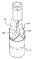
도 2b는 도 2a의 판막의 실시형태에 대한 투시도이고;
도 2c는 개방 구성의 인공 판막의 실시형태에 대한 축방향도이며;
도 2d는 폐쇄 구성의 도 2a의 인공 판막의 실시형태에 대한 축방향도이고;
도 3은 평편한 배향으로 펼친 첨판 프레임의 실시형태에 대한 도면이며;
도 4a는 생체 구조 내 경카테터 전달 시스템의 실시형태에 대한 측면도이고;
도 4b는 생체 구조 내 외과용 판막의 실시형태에 대한 측면도이며;
도 5는 일 실시형태에 따라, 어셈블리 맨드릴(assembly mandrel) 위 첨판 프레임의 측면도이며;
도 6a는 일 실시형태에 따라, 절삭 맨드릴 위 첨판 프레임의 측면도이고;
도 6b는 도 6a의 어셈블리 맨드릴 위 첨판 프레임의 투시도이다.BRIEF DESCRIPTION OF THE DRAWINGS The accompanying drawings are included to provide a further understanding of the subject matter, and are incorporated in and constitute a part of this specification, illustrate the embodiments described herein, and together with the description, It serves to explain.
1A is a sketch of aortic valve;
FIG. 1B is a cross-section of the aortic valve of FIG. 1A showing an angle associated with a spinal heart valve; FIG.
2A is a side view of a prosthetic valve according to one embodiment;
Figure 2b is a perspective view of an embodiment of the valve of Figure 2a;
Figure 2C is an axial view of an embodiment of an open valve prosthesis;
Figure 2D is an axial view of an embodiment of the prosthetic valve of Figure 2A in a closed configuration;
Figure 3 is a view of an embodiment of a prism frame laid out in a flat orientation;
4A is a side view of an embodiment of an in-vivo catheter delivery system;
Figure 4b is a side view of an embodiment of an in-vivo surgical valve;
Figure 5 is a side view of an assembly mandrel overhead frame, according to one embodiment;
6A is a side view of a cutting mandrel overboard frame, in accordance with one embodiment;
6B is a perspective view of the assembly mandrel top plate frame of FIG. 6A.
당업자는 본 개시 내용의 다양한 양태가 의도된 기능을 수행하도록 구성된 여러 가지의 방법 및 장치에 의해 실현될 수 있다는 것을 쉽게 확인할 것이다. 다르게 언급하자면, 다른 방법과 장치가 의도된 기능을 수행하도록 본원에서 일체화될 수 있다. 또한 본원에서 언급된 첨부 도면은 반드시 일정한 비율로 그려지지는 않지만, 본 개시 내용의 다양한 양태를 예시하기 위해 과장될 수 있다는 사실에 주의해야 하며, 이에 관해, 도면은 제한으로서 해석되지는 않는다.Those skilled in the art will readily appreciate that the various aspects of the present disclosure may be realized by various methods and apparatuses configured to perform the intended function. In other instances, other methods and apparatus may be incorporated herein to perform the intended function. It should also be noted that the accompanying drawings referred to herein are not necessarily drawn to scale, but may be exaggerated to illustrate various aspects of the disclosure, and the drawings are not to be construed as limitations thereof.
본원에서 실시형태가 다양한 원리 및 확신과 관련하여 기재될 수 있지만, 기재한 실시형태는 이론에 의해 제약되지는 않는다. 예를 들어, 실시형태가 본원에서 인공 판막, 더 구체적으로는 심장병의 인공 판막에 관해 기재된다. 그러나 본 개시 내용의 범위 내에서 실시형태는 임의의 판막 또는 유사 구조의 메커니즘 및/또는 기능에 적용될 수 있다. 또한, 본 개시 내용의 범위 내에서 실시형태는 비심장병 응용 분야에 적용될 수 있다.Although the embodiments herein may be described in connection with various principles and assurances, the described embodiments are not limited by theory. For example, embodiments are described herein with regard to artificial valves, more specifically artificial valves of heart disease. However, within the scope of the present disclosure, embodiments may be applied to any valve or similar mechanism mechanism and / or function. Also, within the scope of this disclosure, embodiments can be applied to non-cardiac applications.
인공 판막의 문맥에서, 본원에서 사용되는 바와 같이, 용어 첨판은 일방향 판막의 구성 요소이며, 여기서 첨판은 압력 차의 영향 하에 개폐 위치 사이에 이동하도록 조작가능하다. 개방 위치에서, 첨판은 혈액이 판막을 통해 흐르게 한다. 폐쇄 위치에서, 첨판은 실질적으로 판막을 통해 역류하는 것을 차단한다. 다중 첨판을 포함하는 실시형태에서, 각 첨판은 하나 이상의 인접 첨판과 공동으로 혈액의 역류를 차단한다. 혈액에서 압력 차는 예를 들어 심장의 심실 또는 심방의 수축에 의해 야기되며, 이러한 압력 차는 전형적으로 폐쇄될 때 첨판의 한 측면에 유체 압력 축적을 초래한다. 판막의 유입 측에서 압력이 판막의 유출 측에서 압력을 넘어서 상승할 때, 첨판이 열리고, 혈액은 이들 통해 흐른다. 혈액이 판막을 통해 인접 챔버 또는 혈관으로 흐를 때, 유입 측에서 압력은 유출 측에서 압력과 같아진다. 판막의 유출 측에서 압력이 판막의 유입 측에서 혈액 압력을 넘어서 상승할 때, 첨판은 폐쇄 위치로 복귀하여, 일반적으로 판막을 통한 혈액의 역류를 방지한다.In the context of a prosthetic valve, as used herein, the term plunger is a component of a one-way valve, wherein the plunger is operable to move between open and closed positions under the influence of a pressure differential. In the open position, the tip allows blood to flow through the valve. In the closed position, the pivot block substantially prevents backflow through the valve. In embodiments involving multiple plumes, each pledget blocks reflux of blood in association with one or more proximal plumes. Pressure differentials in the blood are caused, for example, by contraction of the ventricles or atria of the heart, which typically results in fluid pressure buildup on one side of the cusp when closed. When the pressure at the inlet side of the valve rises above the outlet at the outlet side of the valve, the valve opens and the blood flows through them. When blood flows into the adjacent chamber or vein through the valve, the pressure at the inflow side equals the pressure at the outflow side. When the pressure at the outflow side of the valve rises above the blood pressure at the inflow side of the valve, the tip returns to its closed position and generally prevents backflow of blood through the valve.
본원에서 사용되는 바와 같이, 용어 막(membrane)은 예컨대 발포 불소중합체, 그러나 이에 한정되지 않는 단일 조성물을 포함하는 물질의 시트를 의미한다.As used herein, the term membrane refers to a sheet of material including, for example, a foamed fluoropolymer, but not limited to a single composition.
본원에서 사용되는 바와 같이, 용어 복합 재료는 예컨대 발포 불소중합체, 그러나 이에 한정되지 않는 막, 및 예컨대 플루오로엘라스토머, 그러나 이에 한정되지 않는 엘라스토머의 조합을 의미한다. 엘라스토머는 막의 다공성 구조 내에 흡수되거나, 막의 한 면 또는 양면에 코팅되거나, 막에 코팅과 막 내 흡수의 조합일 수 있다.As used herein, the term composite refers to a combination of, for example, a foamed fluoropolymer, but not limited thereto, and an elastomer such as, but not limited to, a fluoroelastomer. The elastomer may be absorbed within the porous structure of the membrane, coated on one or both sides of the membrane, or a combination of coating and membrane absorption.
본원에서 사용되는 바와 같이, 용어 적층체는 막, 복합 재료, 또는 다른 물질, 예컨대 엘라스토머, 및 이들의 조합의 다수 층을 의미한다.As used herein, the term laminate refers to multiple layers of membranes, composites, or other materials such as elastomers, and combinations thereof.
본원에서 사용되는 바와 같이, 용어 필름은 총칭으로 막, 복합 재료, 또는 적층체 중 1 이상을 의미한다.As used herein, the term film generally refers to one or more of a film, a composite material, or a laminate.
본원에서 사용되는 바와 같이, 용어 생체적합성 물질은 총칭으로 필름 또는 예컨대 소 심막, 그러나 이에 한정되지 않는 생물 물질을 의미한다.As used herein, the term biocompatible material generally refers to a film or a biomaterial such as, but not limited to, a bovine pericardium.
용어 첨판 윈도는 첨판이 연장되는 프레임이 한정하는 공간으로서 정의된다. 첨판은 프레임 요소로부터 연장될 수 있거나, 프레임 요소에 인접하고, 이로부터 이격될 수 있다.The term platoon window is defined as the space defined by the extension of the frame. The spikes may extend from the frame elements, or may be adjacent to and spaced from the frame elements.
용어 천연 판막 오리피스 및 조직 오리피스는 인공 판막이 위치할 수 있는 해부 구조를 의미한다. 이러한 해부 구조는 심장병 판막이 수술로 제거될 수 있었거나 제거될 수 없었던 위치를 포함하나, 이에 한정되지 않는다. 인공 판막을 수용할 수 있는 다른 해부 구조는 당연히 정맥, 동맥, 도관 및 션트(shunt)를 포함하나, 이에 한정되지 않는다. 본원에서 천연 판막을 인공 판막으로 교체하는 것을 참조하지만, 당연히 판막 오리피스 또는 이식 부위는 또한 특정 목적상 판막을 수용할 수 있는 합성 또는 생물 도관의 위치를 의미할 수 있으며, 따라서 본원에서 제공되는 실시형태의 범위는 판막 교체에 한정되지 않는다.The term natural valve orifice and tissue orifice refers to the anatomy where the prosthetic valve can be located. Such anatomical structures include, but are not limited to, locations where heart valves could or could not be surgically removed. Other anatomical structures capable of receiving a prosthetic valve include, but are not limited to, veins, arteries, conduits, and shunts. Although reference is made herein to replacing a natural valve with a prosthetic valve, it should be understood that the valve orifice or implantation site may, of course, also refer to the location of a synthetic or biological conduit which is capable of receiving a valve for a particular purpose, Is not limited to valve film replacement.
본원에서 사용되는 바와 같이, "결합"은 직접으로 또는 간접으로든지, 및 영구적으로 또는 일시적으로든지. 결합, 연결, 부착, 접착, 첩부, 또는 접합을 의미한다.As used herein, "bond" means either directly or indirectly, and either permanently or temporarily. Joining, connecting, attaching, gluing, attaching, or bonding.
본원에서 사용되는 바와 같이, 절단되거나 절단은 본체의 크기를 줄이는 평면에 의해 3차원 본체의 절단을 의미한다. 도 2d에 관해, 절단 구역은 첨판 베이스(143)의 부착 라인(145), 즉 부착 선을 한정하도록 알파 평면을 교차하는 절단 평면에 의해 절단될 수 있는 첨판의 영역이다.As used herein, cutting or cutting means cutting of a three-dimensional body by a plane that reduces the size of the body. 2d, the cutting area is the area of the cusp that can be cut by the
본원에서 실시형태는 예컨대 심장병 판막 교체, 그러나 이에 한정되지 않는, 외과 및 경카테터 배치에 적합한 인공 판막을 위한 다양한 장치, 시스템, 및 방법을 포함한다. 판막은 일방향 판막으로서 조작가능하며, 여기서 판막은 첨판이 열려 흐르게 하며, 판막 오리피스를 폐색하도록 닫히고, 유체 압력 차에 따라 플로를 막는 판막 오리피스를 한정한다.Embodiments herein include various devices, systems, and methods for prosthetic valves suitable for surgical and light catheter placement, including but not limited to cardiac valve replacement. The valve can be manipulated as a one-way valve, in which the valve opens to allow the valve to open, closes the valve orifice, and defines a valve orifice that closes the flow according to fluid pressure differential.
첨판 심장 판막의 길이는 첨판이 둘러싸인 프레임에 관해 이루는 각도에 의해 결정된다. 더 긴 첨판은 프레임에 관해 더 완만한 각도를 갖는다. 더 짧은 첨판은 프레임에 관해 더 가파른 각도를 갖는다. 더 긴 첨판은 더 짧은 첨판보다 더 양호한 성능을 유도한다. 그러나 대부분의 응용 분야에 대해 짧은 판막만이 수용자 위치에 적합할 수 있다. 따라서 판막 설계자는 딜레마를 보여준다. 본 실시형태에서, 짧은 첨판으로서 양호한 성능을 제공하는 첨판 설계가 제공되며, 따라서 짧은 심장 판막을 가능하게 한다.The length of the epicardial valve is determined by the angle that the spinal column makes about the enclosed frame. The longer plate has a gentler angle with respect to the frame. The shorter tip has a steeper angle about the frame. Longer tip leads to better performance than shorter tip. For most applications, however, only short valves may be suitable for receiver location. Therefore, the valve designer shows the dilemma. In this embodiment, a blade design is provided that provides good performance as a short tip, thus enabling a short heart valve.
판막valve
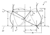
도 1a는 대동맥 판막(5)의 스케치이다. 첨판(1)은 첨판 베이스(3)에서 대동맥 기부(2)에 결합하고 있다. 도 1b는 대동맥 판막(5)의 첨판(1)과 관련된 각도를 보여주는 도 1a의 대동맥 판막(5)의 단면이다. 도 1b는 첨판(1)과 부착 점(7)에서 첨판 베이스(3)를 통해 연장되는 제1 수평선(L1), 및 접합부(commissure)의 접합부 톱(4)을 통해 연장되는 제2 수평선(L2) 사이의 관계를 도시한다. 도 1b에서, 대동맥 판막(5)은 판막 축(X)이 수직인 위치에서 배향되며, 유입 에지(6)는 하방으로 향해 있고, 첨판(1)은 폐쇄 위치에 있다. 부착 각도 알파(α)는 도 1에 도시한 바와 같이, 부착 점(7)에서 첨판(1)의 첨판 베이스(3)의 중심으로부터 연장되는 탄젠트 선(Lt) 및 부착 점(7)에서 첨판 베이스(3)를 통해 연장되는 제1 수평선(L1) 사이의 각도로서 정의된다.1A is a sketch of
첨판(1)이 부착 점(7)에서 첨판(1)의 첨판 베이스(3)의 중심을 통해 축 단면에서 오목형, 직선형, 또는 볼록형을 나타낼 수 있다고 이해된다. 본원에서 제시하고, 이에 한정되지 않는 실시형태의 상세한 설명에 대한 명확성과 단순화를 위해, 첨판(1)의 기하 구조는 부착 점(7)에서 첨판(1)의 첨판 베이스(3)의 중심을 통해 축 단면에서 직선으로서 α를 한정하는 탄젠트 선(Lt)을 갖는 것으로서 기재되어 있다.It is to be understood that the
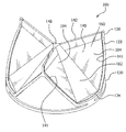
도 2a는 일 실시형태에 따라, 인공 판막(100)의 측면도이다. 도 2b는 도 2a의 인공 판막(100)의 투시도이다. 도 2c와 2d는 각각 개방 및 폐쇄 구성의 도 2a의 인공 판막(100)의 축방향도이다. 도 3은 도 2a의 인공 판막(100)의 첨판 프레임(130)의 측면도이며, 여기서 첨판 프레임(130)은 길이로 잘라내고 열려 있어서 일반적으로 관형 인공 판막(100)의 요소를 더 양호하게 보여준다. 도 2a 및 2b에서, 첨판(140)은 이들이 절삭 맨드릴(712)에 의해 수용될 때처럼 약간 열려서 도시되어 있다. 완전히 폐쇄된 인공 판막(100)은 삼중점(148)을 포함하여, 하류 혈액이 판막을 통해 역류하는 것을 방지하도록 판막을 폐쇄하게 하는 하류 유체 압력의 영향 하에 접합하도록 합치는 첨판들(140)의 첨판 자유 에지들(142)을 가질 것이라고 이해된다.2A is a side view of the
본원에서 제공되는 실시형태는 짧은 판막을 갖는 작은 알파 각도와 더 양호한 첨판 굽힘 거동을 위해 더 긴 첨판을 얻는 더 큰 알파 각도 사이의 긴장에 대해 원하는 해결책을 제공한다. 본원에서 제공되는 실시형태는 첨판 베이스(3)가 절단되는 첨판을 제공함으로써 판막 길이를 감소시키면서 더 큰 알파 각도를 제공하며, 비교적 평편한 첨판 베이스(143)를 제공한다.The embodiments provided herein provide a desired solution to the tension between a small alpha angle with a short valve plate and a larger alpha angle resulting in a longer tip plate for better tip plate bending behavior. Embodiments provided herein provide a relatively flat tipped
본원에서 실시형태에 따라, 소정의 판막 구조의 부착 각도 알파(α)는 첨판 높이가 감소할 때 보존된다. 이는 첨판의 베이스를 도 1a에 도시한 바와 같이 일반적으로 포물선 첨판 형상에 관해 부착 점(7)이 아니라, 도 2a와 2d에 도시한 바와 같이 첨판(140)의 첨판 베이스(143)에서 판막 축(X)에 수직인 판막 단면 평면에서 수평선에 평행한 부착 선(145)으로서 다시 한정함으로써 달성된다.According to embodiments herein, the attachment angle alpha (alpha) of a given valve structure is preserved when the tip height decreases. This is because the base of the tip plate is not attached to the
본원에서 제공되는 실시형태를 가시화하는 수단으로서, 도 1b에 관해, 제1 수평선(L1)은 이것이 접합부 톱(4) 쪽으로 판막 축(X)을 따라 수직으로 이동할 때 첨판 베이스(3)를 통해 연장된다. 알파 평면(AP)으로서 언급된, 제1 수평선(L1)을 포함하고, 판막 축(X)에 수직인 평면은 부착 선(145)을 따라 도 2a의 첨판(140)을 교차한다. 첨판 베이스(3)는 알파 평면(AP)에 의해 절단되며, 여기서 첨판 베이스(3)의 부착 점(7)은 도 1a에 도시한 부착 점(7)에서 첨판(1)의 첨판 베이스(3)와 비교할 때, 도 2a, 2b 및 2d에 도시한 바와 같이 첨판 베이스(143)의 부착선(145), 즉 점이 아니라 부착선이 된다.1b, the first horizontal line L1 extends through the
도 2b에 관해, 첨판들(140)의 정점(147)을 연결하는 정점 선(La)이 표시되어 있다. 정점 선(La)은 첨판(140)을 첨판 프레임(130)에 인접한 제1 영역(149a), 및 첨판 자유 에지에 인접한 제2 영역(149b)으로 분할한다. 제1 영역(149a)은 절단된 구역을 한정한다. 절단된 구역은 첨판 베이스(143)에 인접한 첨판(140)의 하부 섹션에 위치한다. 절단 구역은 첨판 베이스(143)의 부착선(145), 즉 부착의 선을 한정하도록 알파 평면(AP)에 의해 절단될 수 있는 영역이다.Referring to FIG. 2B, a vertex line La connecting the
프레임frame
도 2a-2d에 관해, 첨판 프레임(130)은 일 실시형태에 따라, 개구(122)의 일반적인 개방 패턴을 한정하는 일반적으로 관형 부재이다. 경카테터 실시형태에 따라, 첨판 프레임(130)은 상이한 직경 사이에서 (120)을 압축 및 확장하도록 조작가능하다. 첨판 프레임(130)은 프레임 제1 단부(121a)와 이 프레임 제1 단부(121a) 맞은편의 프레임 제2 단부(121b)를 포함한다. 도 2a에 도시한 바와 같이, 첨판 프레임(130)은 첨판 프레임 외부 표면(126a)과 첨판 프레임 외부 표면(126a) 맞은편의 첨판 프레임 내부 표면(126b)을 포함한다. 첨판 프레임(130)은 첨판 자유 에지(142)에 결합하는 접합부 기둥(commissue post)(136)을 한정한다.2a-2d, the
첨판 프레임(130)은 스텐트와 같이 본 기술에서 알려진 구조를 포함할 수 있다. 스텐트는 생체 구조로 경피 경카테터 전달에 적합한 직경이 작을 수 있는 관형 부재이며, 생체 구조로 전개될 때 더 큰 직경으로 확장될 수 있다. 다양한 설계와 물질 특성을 가진 스텐트가 본 기술에서 잘 알려져 있다.The
첨판 프레임(130)은 피처를 얼마든지, 반복가능하게 또는 아니면, 예컨대 기하 형상 및/또는 직선 또는 곡류의 일련의 동양혈관(sinusoid)을 한정할 수 있다. 기하 형상은 실질적으로 균일한 원주 압축과 확장을 용이하게 하는 임의 형상을 포함할 수 있다. 첨판 프레임(130)은 컷 튜브(cut tube), 또는 특정 목적에 적합한 임의의 다른 요소를 포함할 수 있다. 첨판 프레임(130)은 식각되거나, 잘라내거나, 레이저로 잘라내거나, 튜브 또는 물질의 시트로 찍어낼 수 있으며, 그 후 시트는 실질적으로 원통 구조로 형성될 수 있다. 대안으로, 세장 재료, 예컨대 와이어, 구부릴 수 있는 스트립, 또는 이들의 일련의 재료를 구부리거나 꼰 다음, 실질적으로 원통 구조로 형성할 수 있으며, 여기서 원통 벽은 일반적으로 균일한 원주 방식으로 더 작은 직경으로 압축가능하고, 더 큰 직경으로 확장가능한 열린 골격을 포함한다.The
첨판 프레임(130)은 임의의 금속 또는 중합체 생체적합성 물질을 포함할 수 있다. 예를 들어, 첨판 프레임(130)은 예컨대 니티놀, 코발트 니켈 합금, 스테인리스강, 또는 폴리프로필렌, 아세틸 단독 중합체, 아세틸 공중합체, ePTFE, 다른 합금 또는 중합체, 또는 본원에서 기재한 바와 같이 작용하는 적합한 물리적 및 기계적 특성을 가진 임의의 다른 생체적합성 물질, 그러나 이들에 한정되지 않는, 물질을 포함할 수 있다.The
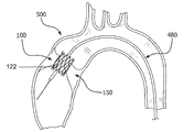
실시형태에 따라, 첨판 프레임(130)은 인공 판막(100)의 경카테터 전개를 나타내는 도 4a에 도시한 바와 같이, 이식 부위와 포지티브(positive) 맞물림을 제공하여 인공 판막(100)을 부위에 단단히 고정하도록 구성될 수 있다. 일 실시형태에 따라, 첨판 프레임(130)은 위치를 유지하는 조직 오리피스(150)에 대해 충분한 병렬(apposition)을 유지하도록 약간의 탄성 수축력이 있는 충분히 강성인 프레임을 포함할 수 있다. 또 다른 실시형태에 따라, 첨판 프레임(130)은 조직 오리피스(150)보다 더 큰 직경으로 확장하도록 구성될 수 있어서, 인공 판막(100)이 조직 오리피스(150)로 확장될 때, 이것은 내부에 견고하게 자리를 잡을 수 있다. 또 다른 실시형태에 따라, 첨판 프레임(130)은 이식 부위, 예컨대 조직 오리피스(150)를 맞물려 인공 판막(100)을 이식 부위에 단단히 고정하도록 구성되는 1 이상의 앵커(anchor)(도시 안 됨)를 포함할 수 있다.According to an embodiment, the
인공 판막(100)을 이식 부위에 결합하기 위한 다른 요소 또는 수단이 당연히 예상된다. 일예로서, 그러나 이에 한정되지 않으며, 다른 수단, 예컨대 기계적 및 접착제 수단이 인공 판막(100)을 합성 또는 생물 도관에 결합하는데 사용될 수 있다.Other elements or means for coupling the
후에 설명되는 바와 같이, 외과용 인공 판막(100) 실시형태는 외과용 인공 판막(100)이 고정 직경으로 될 수 있으며, 압축 및 재확장되도록 조작가능할 필요가 없으므로 지그재그 구조일 수 있거나 아닐 수 있다.As will be described later, the surgical
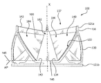
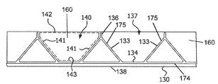
도 3은 첨판 프레임(130)의 측면도이며, 여기서 첨판 프레임(130)은 길이로 잘라내고, 열려 있어서 도 2b의 인공 판막(100)의 첨판 프레임(130)의 요소를 더 양호하게 도시한다. 첨판 프레임(130)은 베이스 요소(138)와 베이스 요소(138)에 의해 상호연결되는 다수의 이격된 이등변 삼각형 요소(174)를 포함한다. 각 첨판 윈도(137)는 한 삼각형 요소(174)의 측면(175)인 첨판 윈도 사이드(133) 및 인접 삼각형 요소(174)의 측면(175)인 또 다른 첨판 윈도 사이드(133)에 의해 한정되며, 각 첨판 윈도 베이스(134)는 베이스 요소(138)에 의해 한정되고, 각 첨판 윈도(137)는 이등변 사각형을 한정한다. 인공 판막(100)의 실시형태에 따라, 각 첨판(140)은 2개의 첨판 측면(141), 첨판 베이스(143) 및 첨판 베이스(143) 맞은편의 첨판 자유 에지(142)를 가진 이등변 사각형 형상을 실질적으로 가지며, 여기서 2개의 첨판 측면(141)은 도 3에 점선으로 도시한 바와 같이, 첨판 베이스(143)로부터 분기하고, 첨판 베이스(143)는 실질적으로 평편하다. 첨판 프레임(130)은 추가로 첨판 자유 에지(142)가 연장되는 접합부 기둥(136)을 한정한다.Figure 3 is a side view of the
일 실시형태에 따라, 첨판 프레임(130)은 프레임 제1 단부와 이 프레임 제1 단부 맞은편의 프레임 제2 단부를 포함하며, 첨판 윈도는, 프레임의 관 형상에 2차원 이등변 사각형을 감쌈으로써(wrapping), 적어도 부분적으로, 결정된 형상을 가지며, 이등변 사각형은 베이스와 이 베이스로부터 분기하는 2개의 측면이 있고, 여기서 인접 이등변 사각형으로부터 한 측면이 프레임 제2 단부에서 만난다.According to one embodiment, the
경카테터 인공 판막(100) 실시형태에서, 첨판 프레임(130)은 경피 경카테터 고정 및 전달을 수용하는 비교적 작은 직경을 얻도록 탄성적으로, 소성적으로, 또는 둘 다로 압축가능하다.In the case of the catheter
일 실시형태에 따라, 첨판 프레임(130)은 하중 하에 휘고, 하중이 제거될 때 처음 형상으로 복원되도록 조작가능한 형상 기억 물질을 포함하며, 따라서 첨판 프레임(130)이 압축 형상에서 소정 형상으로 자기 확장하게 한다. 일 실시형태에 따라 첨판 프레임(130)은 발룬에 의해 확장되도록 소성적으로 변형가능하다. 또 다른 실시형태에서, 첨판 프레임(130)은 자기 확장하도록 탄성적으로 변형가능하다.According to one embodiment, the
필름film
필름(160)은 실시형태에 따라, 생물학적으로 적합하며, 첨판에 프레임까지 결합하도록 구성되는 임의의 시트류 재료이다. 용어 "필름"이 특정 목적에 적합한 1 이상의 생체적합성 물질에 대해 총칭으로 사용된다고 이해된다. 첨판(140)은 또한 필름(160)으로 이루어진다.The
일 실시형태에 따라, 생체적합성 물질은 생물 원이 아니고, 생체적합성 중합체와 같이, 특정 목적을 위해 충분히 유연하고, 강한 필름(160)이다. 일 실시형태에서, 필름(160)은 복합체로서 언급된, 엘라스토머와 배합되는 생체적합성 중합체를 포함한다.According to one embodiment, the biocompatible material is not a biogenic source, and is a
다양한 형태의 필름(160)에 대한 세부 내용은 하기에 설명된다. 일 실시형태에서, 필름(160)은 적어도 부분적으로 첨판 프레임(130)을 덮는 일반적으로 관형 재료로부터 형성될 수 있다. 필름(160)은 막, 복합 재료, 또는 적층체 중 1 이상을 포함할 수 있다. 다양한 형태의 필름(160)에 대한 세부 내용은 하기에 설명된다.Details of the various types of
첨판Crown
각 첨판 윈도(137)에 필름(160)과 같은 생체적합성 물질이 제공되며, 이는 도 2a 및 3에 도시한 바와 같이, 첨판 윈도 사이드(133)의 일부에 결합하고, 필름(160)은 첨판(140)을 한정한다. 각 첨판(140)은 일 실시형태에 따라, 첨판 자유 에지(142)와 첨판 베이스(143)를 한정한다. 하기에 기재되는 바와 같이, 첨판 베이스(143) 구조에 대한 다수 실시형태가 제공될 수 있다고 예상된다. 일 실시형태에 따라, 필름(160)은 첨판 윈도 사이드(133)의 부분에 그리고 첨판 윈도 베이스(134)에 결합하고, 여기서 첨판(140)은 첨판 윈도 사이드(133)의 부분과 첨판 윈도 베이스(134)에 의해 한정된다. 또 다른 실시형태에 따라, 필름(160)은 첨판 윈도 사이드의 부분에 결합한다.Each
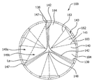
첨판(140)이 완전 개방 위치에 있을 때, 인공 판막(100)은 도 2c에 도시한 바와 같이 실질적으로 원형 판막 오리피스(102)를 나타낸다. 첨판(140)이 개방 위치에 있을 때 판막 오리피스(102)를 통해 유체 흐름이 허용된다.When the
첨판(140)이 개폐 위치 사이에서 순환할 때, 첨판(140)은 일반적으로 첨판이 결합하는 첨판 윈도 사이드(133)의 부분 및 첨판 베이스(143) 주위에 구부러진다. 인공 판막(100)이 폐쇄될 때, 도 2d에 도시한 바와 같이, 일반적으로 각 첨판 자유 에지(142)의 약 반이 인접 첨판(140)의 첨판 자유 에지(142)의 인접한 반에 접해 있다. 도 2d의 실시형태 중 3개의 첨판(140)은 삼중점(148)에서 만난다. 판막 오리피스(102)는 첨판(140)이 유체 흐름을 중단하는 폐쇄 위치에 있을 때 폐색된다.When the
도 2d에 관해, 일 실시형태에 따라, 각 첨판(140)은 중앙 영역(182)과 이 중앙 영역(182)의 양측에 있는 2개의 측면 영역(184)을 포함한다. 중앙 영역(182)은 2개의 중앙 영역 측면(183), 첨판 베이스(143) 및 첨판 자유 에지(142)에 의해 한정된 실질적인 삼각형 형상에 의해 한정된다. 2개의 중앙 영역 측면(183)은 첨판 베이스(143)로부터 첨판 자유 에지(142)로 모인다.2d, each
일 실시형태에 따라, 중앙 영역(182)은 인공 판막(100)이 폐쇄 위치에 때 실질적으로 평면이다.According to one embodiment, the
첨판(140)은 예를 들어 심장의 심실 또는 심방의 수축에 의해 야기된 혈액의 압력 차에서 동작하도록 구성될 수 있으며, 이러한 압력 차는 전형적으로 폐쇄될 때 인공 판막(100)의 한 측면에 유체 압력 축적을 초래한다. 인공 판막(100)의 유입 측 위 압력이 인공 판막(100)의 유출 측 위 압력보다 상승할 때, 첨판(140)이 열리고, 혈액은 이를 통해 흐른다. 혈액이 인공 판막(100)을 통해 인접 챔버 또는 혈관으로 흐를 때, 압력은 같아진다. 인공 판막(100)의 유출 측 위 압력이 인공 판막(100)의 유입 측 위 혈액 압력보다 상승할 때, 첨판(140)은 폐쇄 위치로 복귀하여 일반적으로 인공 판막(100)의 유입 측을 통한 혈액의 역류를 방지한다.The
첨판 프레임(130)은 실시형태에 따라, 특정 목적에 적합한, 다수의 첨판 윈도(137), 및 따라서 첨판들(140)을 포함할 수 있다고 이해된다. 1, 2, 3개 이상의 첨판 윈도(137) 및 상응하는 첨판(140)을 포함하는 첨판 프레임(130)이 예상된다.It is understood that the
경카테터 배치에 적합한 인공 판막(100)의 실시형태에 따라, 인공 판막(100)은 더 작은 직경을 가진 축소 구성으로 압축될 수 있고, 확장 구성으로 확장될 수 있어서, 인공 판막(100)이 축소 구성으로 카테터를 통해 전달될 수 있으며, 도 4a에 도시한 바와 같이 조직 오리피스(150) 내에 전개 시 확장될 수 있다. 첨판 프레임(130)은 축소 구성으로부터 확장 구성으로 이행될 때 원주 균일성을 회복하도록 조작가능할 수 있다.According to an embodiment of the
인공 판막(100)은 특정 목적에 적합한 전달 카테터 상에 고정될 수 있다. 접축소 구성에서의 인공 판막(100)의 직경은 부분적으로 프레임의 두께 및 첨판 두께에 의해 측정된다.The
첨판Crown 필름 film
첨판(140)을 구성하는 생체적합성 물질은 임의의 생물 조직 또는 충분히 적합하고, 유연한, 합성, 생체적합성 물질, 예컨대 생체적합성 중합체를 포함할 수 있다. 일 실시형태에서, 첨판(140)은 복합체로서 지칭되는, 엘라스토머와 배합되는 생체적합성 중합체를 포함한다. 일 실시형태에 따른 물질은 피브릴(fibril)의 매트릭스 내에 다수의 공간을 포함하는 발포 불소중합체 막, 및 엘라스토머 물질을 포함하는 복합 재료를 포함한다. 당연히 본 개시 내용의 범위 내에 속하면서 다수 형태의 불소중합체 막과 다수 형태의 엘라스토머 물질이 배합되어 적층체를 형성할 수 있다. 또한 본 개시 내용의 범위 내에 속하면서 엘라스토머 물질은 당연히 다수 엘라스토머, 다수 형태의 비엘라스토머 성분, 예컨대 무기 충전제, 치료제, 방사선 불투과 표지자, 등을 포함할 수 있다.The biocompatible material that constitutes the
일 실시형태에 따라, 복합 재료는 예를 들어 바시노(Bacino)의 미국특허 제7,306,729호에 일반적으로 기재되어 있는 바와 같이, 다공성 ePTFE 막으로부터 제조된 발포 불소중합체 물질을 포함한다.According to one embodiment, the composite material comprises a foamed fluoropolymer material made from a porous ePTFE membrane, for example, as generally described in U.S. Patent No. 7,306,729 to Bacino.
기재한 발포 불소중합체 물질을 형성하는데 사용되는 발포성 불소중합체는 PTFE 단독 중합체를 포함할 수 있다. 대체 실시형태에서, PTFE, 발포성 개질 PTFE 및/또는 PTFE의 발포 공중합체의 블렌드가 사용될 수 있다. 적합한 불소중합체 물질의 비제한적인 일예는 예를 들어 브란카(Branca)의 미국특허 제5,708,044호, 베일리(Baillie)의 미국특허 제6,541,589호, 사볼(Sabol) 외 그의 공동발명자의 미국특허 제7,531,611호, 포드(Ford)의 미국특허 출원 제11/906,877호, 쉬(Xu) 외 그의 공동발명자의 미국특허 출원 제12/410,050호에 기재되어 있다.The expandable fluoropolymer used to form the described foamed fluoropolymer material may comprise a PTFE homopolymer. In alternative embodiments, a blend of expanded copolymers of PTFE, expandable modified PTFE and / or PTFE may be used. Non-limiting examples of suitable fluoropolymer materials are described, for example, in U.S. Patent No. 5,708,044 to Branca, U.S. Patent No. 6,541,589 to Baillie, U.S. Patent No. 7,531,611 to Sabol et al. , U.S. Patent Application No. 11 / 906,877 to Ford, and U.S. Patent Application No. 12 / 410,050 to Xu et al.
발포 불소중합체 막은 원하는 첨판 성능을 달성하기 위해 임의의 적합한 미세구조를 포함할 수 있다. 일 실시형태에 따라, 발포 불소중합체는 예컨대 고어(Gore)의 미국특허 제3,953,566호에 기재된, 피브릴에 의해 상호연결되는 노드(node)의 미세구조를 포함한다. 피브릴은 다수의 방향으로 노드로부터 방사상으로 연장되며, 막은 일반적으로 균질 구조를 갖는다. 이러한 미세구조를 가진 막은 전형적으로 2 미만, 및 가능하게는 1.5 미만의 2 직교 방향에서 매트릭스 인장 강도 비를 나타낼 수 있다.The foamed fluoropolymer film may comprise any suitable microstructure to achieve the desired foil performance. According to one embodiment, the foamed fluoropolymer includes the microstructure of a node interconnected by a fibril, such as described in US Pat. No. 3,953,566 to Gore. The fibrils extend radially from the nodes in a number of directions, and the films generally have a homogeneous structure. Films with such microstructures can exhibit a matrix tensile strength ratio in two orthogonal directions, typically less than 2, and possibly less than 1.5.
또 다른 실시형태에서, 발포 불소중합체 막은 바시노의 미국특허 제7,306,729호가 일반적으로 교시하는 바와 같이, 실질적으로 피브릴만의 미세구조를 갖는다. 실질적으로 피브릴만을 가진 발포 불소중합체 막은 높은 표면적, 예컨대 20 ㎡/g 초과, 또는 25 ㎡/g 초과의 표면적을 가질 수 있으며, 일부 실시형태에서 1.5 x 10⁵ MPa2 이상의 2 직교 방향에서 매트릭스 인장 강도의 곱, 및/또는 4 미만, 및 가능하게는 1.5 미만의 2 직교 방향에서 매트릭스 인장 강도 비를 가진 고 균형(highly balanced) 강도 재료를 제공할 수 있다.In yet another embodiment, the foamed fluoropolymer film has a substantially fibril microstructure, as taught generally by Bassino, U.S. Patent No. 7,306,729. A foamed fluoropolymer film having substantially only fibrils may have a surface area as high as the surface area, such as greater than 20
발포 불소중합체 막은 원하는 첨판 성능을 달성하기 위해 임의의 적합한 두께와 질량을 갖도록 맞춰질 수 있다. 일예로서, 그러나 이에 한정되지 않게, 첨판(140)은 두께가 약 0.1 ㎛인 발포 불소중합체 막을 포함한다. 발포 불소중합체 막은 약 1.15 g/㎡의 면적당 질량을 가질 수 있다. 본 발명의 일 실시형태에 따른 막은 매트릭스 인장 강도가 종 방향에서 약 411 MPa 및 횡 방향에서 315 MPa일 수 있다.The foamed fluoropolymer film can be tailored to have any suitable thickness and mass to achieve the desired foil performance. By way of example, but not of limitation, the
추가 물질이 첨판의 원하는 특성을 향상시키기 위해 세공으로 또는 막의 물질 내에 또는 막의 층 사이에 혼입될 수 있다. 본원에서 기재한 복합 재료는 원하는 첨판 성능을 달성하기 위해 임의의 적합한 두께와 질량을 갖도록 맞춰질 수 있다. 실시형태에 따른 복합 재료는 불소중합체 막을 포함할 수 있으며, 두께가 약 1.9 ㎛이고, 면적당 질량이 약 4.1 g/㎡일 수 있다.Additional materials may be incorporated into the pores or within the material of the membrane or between layers of the membrane to enhance the desired properties of the membrane. The composite materials described herein can be tailored to have any suitable thickness and mass to achieve the desired foil performance. The composite material according to an embodiment may comprise a fluoropolymer film and may have a thickness of about 1.9 占 퐉 and a mass per area of about 4.1 g / m2.
엘라스토머와 배합되어 복합 재료를 형성하는 발포 불소중합체 막은 다양한 방식으로 고 사이클의 유연한 이식 응용 분야, 예컨대 심장 판막 첨판에 사용하는데 필요한 성능 속성들이 있는 본 개시 내용의 요소를 제공한다. 예를 들어, 엘라스토머의 첨가로 ePTFE만의 재료에 의해 관찰되는 경화를 제거하거나 줄임으로써 첨판의 피로 성능을 개선할 수 있다. 추가로, 이것은 물질이 성능 손상을 초래할 수 있는 영구 변형, 예컨대 구김 또는 주름을 겪을 가능성을 줄일 수 있다. 일 실시형태에서, 엘라스토머는 발포 불소중합체 막의 다공 구조 내 실질적으로 모든 세공 부피 또는 공간을 차지한다. 또 다른 실시형태에서 엘라스토머는 하나 이상의 불소중합체 층의 실질적으로 모든 세공 내에 존재한다. 엘라스토머를 세공 부피에 채우거나 실질적으로 모든 세공 내에 존재하게 하는 것은 외부 물질이 바람직하지 않게 복합체로 혼입될 수 있는 공간을 줄인다. 이러한 외부 물질의 일예는 혈액과 접촉으로부터 막에 들어올 수 있는 칼슘이다. 예를 들어, 심장 판막 첨판에서 사용되는 바와 같이, 칼슘이 복합 재료에 혼입되게 되면, 개폐 순환 중에 기계적 손상이 일어날 수 있으며, 따라서 첨판에 구멍의 형성과 혈행 동태에서 악화를 유발할 수 있다.Foamed fluoropolymer membranes blended with elastomers to form composites provide elements of the present disclosure with the performance attributes necessary for use in high cycle flexible implant applications, such as heart valve plates, in a variety of ways. For example, the addition of an elastomer can improve the fatigue performance of the plate by eliminating or reducing the hardening observed by the ePTFE-only material. In addition, this may reduce the likelihood that the material undergoes permanent deformation, such as creasing or wrinkling, which may result in performance impairment. In one embodiment, the elastomer occupies substantially all of the pore volume or space within the porous structure of the foamed fluoropolymer film. In yet another embodiment, the elastomer is present in substantially all of the pores of the at least one fluoropolymer layer. Filling the elastomer in the pore volume or allowing it to be present in virtually all of the pores reduces the space in which the foreign material may be undesirably incorporated into the composite. An example of such an external material is calcium that can enter the membrane from contact with blood. For example, as used in cardiac valve cusps, calcium incorporation into the composite can cause mechanical damage during open-and-close circulation, which can lead to hole formation and deterioration in blood circulation in the epilator.
일 실시형태에서, ePTFE와 배합되는 엘라스토머는 예컨대 창(Chang) 외 그의 공동발명자의 미국특허 제7,462,675호에 기재되어 있는, 테트라플루오로에틸렌(TFE)과 퍼플루오로메틸 비닐 에테르(PMVE)의 열가소성 공중합체이다. 상기에 논의한 바와 같이, 엘라스토머가 발포 불소중합체 막 내에 실질적으로 모든 공간 또는 세공을 차지하여 복합 재료를 형성하도록 발포 불소중합체 막과 배합된다. 엘라스토머에 의한 발포 불소중합체 막의 세공에 대한 이러한 충전은 다양한 방법으로 수행될 수 있다. 일 실시형태에서, 발포 불소중합체 막의 세공을 충전하는 방법은 발포 불소중합체 막의 세공으로 부분적으로 또는 완전히 유입되는데 적당한 점도와 표면 장력을 가진 용액을 생성하는데 적합한 용매에 엘라스토머를 용해시키는 단계 및 용매를 증발시켜, 충전제를 남기는 단계를 포함한다.In one embodiment, the elastomer blended with ePTFE is a thermoplastic elastomer (e.g., a thermoplastic elastomer) of tetrafluoroethylene (TFE) and perfluoromethyl vinyl ether (PMVE), as described in Chang et al., U.S. Patent No. 7,462,675 Lt; / RTI > As discussed above, the elastomer is combined with the foamed fluoropolymer film to occupy substantially all of the voids or pores in the foamed fluoropolymer film to form a composite material. This filling of the pores of the foamed fluoropolymer film by an elastomer can be carried out in various ways. In one embodiment, the method of filling the pores of the foamed fluoropolymer film comprises the steps of dissolving the elastomer in a solvent suitable for producing a solution having a suitable viscosity and surface tension to partially or completely flow into the pores of the foamed fluoropolymer film, And leaving a filler.
일 실시형태에서, 복합 재료는 3 층: ePTFE의 2 외부 층 및 사이에 배치된 플루오로엘라스토머의 내부 층을 포함한다. 추가의 플루오로엘라스토머가 적합할 수 있으며, 이들은 창 외 그의 공동발명자의 미국특허 출원 공개 제2004/0024448호에 기재되어 있다.In one embodiment, the composite material comprises three layers: two outer layers of ePTFE and an inner layer of a fluoroelastomer disposed therebetween. Additional fluoroelastomers may be suitable and are described in U.S. Patent Application Publication No. 2004/0024448 to Chang et al.
또 다른 실시형태에서, 발포 불소중합체 막의 세공을 충전하는 방법은 분산액을 통해 충전제를 전달하여 발포 불소중합체 막의 세공을 부분적으로 또는 완전히 충전하는 단계를 포함한다.In another embodiment, the method of filling the pores of the foamed fluoropolymer film includes transferring the filler through the dispersion to partially or completely fill the pores of the foamed fluoropolymer film.
또 다른 실시형태에서, 발포 불소중합체 막의 세공을 충전하는 방법은 엘라스토머를 발포 불소중합체 막의 세공에 유입하게 하는 열 및/또는 압력의 조건 하에 다공성 발포 불소중합체 막을 엘라스토머의 시트와 접촉시키는 단계를 포함한다.In yet another embodiment, a method of filling pores of a foamed fluoropolymer membrane includes contacting the porous foamed fluoropolymer membrane with a sheet of elastomer under conditions of heat and / or pressure to cause the elastomer to enter the pores of the foamed fluoropolymer membrane .
또 다른 실시형태에서, 발포 불소중합체 막의 세공을 충전하는 방법은 처음에 세공을 엘라스토머의 프리폴리머(prepolymer)로 충전한 다음 적어도 부분적으로 엘라스토머를 경화시킴으로써 발포 불소중합체 막의 세공 내에 존재하는 엘라스토머를 중합시키는 단계를 포함한다.In another embodiment, a method for filling pores of a foamed fluoropolymer film includes first polymerizing the elastomer present in the pores of the foamed fluoropolymer film by first filling the pores with a prepolymer of the elastomer, and then at least partially curing the elastomer .
엘라스토머의 최소 중량%에 도달한 후, 불소중합체 물질 또는 ePTFE로부터 구성된 첨판은 엘라스토머의 퍼센트를 증가시켜 상당히 증가한 사이클 수명(cylce life)을 얻음으로써 일반적으로 더 양호하게 수행된다. 일 실시형태에서, ePTFE와 배합되는 엘라스토머는 예컨대 창 외 그의 공동발명자의 미국특허 제7,462,675호, 및 당업자에게 공지될 다른 문헌에 기재되어 있는, 테트라플루오로에틸렌과 퍼플루오로메틸 비닐 에테르의 열가소성 공중합체이다. 첨판(140)에 사용하는데 적합할 수 있는 다른 생체적합성 중합체는 우레탄, 실리콘(오르가노폴리실록산), 실리콘 우레탄의 공중합체, 스티렌/이소부틸렌 공중합체, 폴리이소부틸렌, 폴리에틸렌-co-폴리(비닐 아세테이트), 폴리에스테르 공중합체, 나일론 공중합체, 불소화 탄화수소 중합체 및 공중합체 또는 이전의 것들 중 각각의 혼합물의 군을 포함하나, 이들에 한정되지 않는다.After reaching the minimum weight percent of the elastomer, the platelets constructed from the fluoropolymer material or ePTFE are generally better performed by increasing the percentage of elastomer to obtain a significantly increased cycle life. In one embodiment, the elastomer blended with ePTFE is a thermoplastic elastomer of tetrafluoroethylene and perfluoromethyl vinyl ether, as described, for example, in U.S. Patent No. 7,462,675 to Chang et al., And other documents known to those skilled in the art. It is united. Other biocompatible polymers that may be suitable for use in
다른 고려 사항Other Considerations
일 실시형태에 따라, 인공 판막(100)은 예컨대 대동맥 판막 교체 과정에 의해 겪게 될 수 있는, 이식할 때 좌심실에서 다발 갈래(bundle branch)를 피복하지 않음으로써 심장 전도 시스템에 의한 방해를 방지하도록 구성될 수 있다. 예를 들어, 인공 판막(100)은 약 25 mm 미만 또는 약 18 mm 미만의 길이를 포함할 수 있다. 인공 판막(100)은 또한 1 미만의 종횡비를 포함할 수 있으며, 여기서 종횡비는 확장된, 기능 직경(functional diameter)에 대한 인공 판막(100)의 길이 사이의 관계를 나타낸다. 그러나 인공 판막(100)은 임의의 길이로 및 더 일반적으로는, 임의의 바람직한 치수로 구성될 수 있다.According to one embodiment, the
경카테터 실시형태에서, 축소 상태에서, 인공 판막(100)은 확대된 프로파일의 약 35% 미만인 축소 프로파일을 가질 수 있다. 예를 들어, 26 mm의 확장 직경을 포함하는 인공 판막(100)은 약 8 mm 미만, 또는 약 6 mm 미만의 축소 직경을 가질 수 있다. 직경에서 퍼센트 차는 인공 판막(100)의 치수와 재료 및 그의 다양한 응용 분야에 의존하며, 따라서 실제의 퍼센트 차는 본 개시 내용에 의해 한정되지 않는다.In the curative catheter embodiment, in the collapsed state, the
인공 판막(100)은 추가로 생물 활성제를 포함할 수 있다. 일단 인공 판막(100)이 이식되면 약제의 방출 제어를 위해 생물 활성제를 필름(160)의 일부 또는 전체에 코팅할 수 있다. 생물 활성제는 혈관확장제, 항응고제, 항혈소판제, 헤파린과 같으나, 이에 한정되지 않는 항혈전제를 포함할 수 있으나, 이들에 한정되지 않는다. 다른 생물 활성제는 또한 예를 들어 빈카 알칼로이드(즉 빈블라스틴, 빈크리스틴, 및 비노렐빈), 패클리탁셀, 에피디포도필로톡신(즉 에토포시드, 테니포시드)와 같은 천연 산물을 포함하는 항증식제/항유사분열제, 항생제(닥티노마이신(악티노마이신 D), 다우노루비신, 독소루비신 및 이다루비신), 안트라사이클린, 미토크산트론, 블레오마이신, 플리카마이신(미트라마이신) 및 미토마이신, 효소(L-아스파라긴을 전신으로 대사시키고, 세포로서 이들 자신의 아스파라긴을 합성하는 능력을 가지지 못한 세포를 제거하는 L-아스파라기나제); 항혈소판제 예컨대 G(GP) IIb/IIIa 억제제 및 비트로넥틴 수용체 길항제; 항증식/항유사분열 알킬화제 예컨대 질소 머스타드(메클로르에타민, 사이클로포스파미드 및 유사체, 멜팔란, 클로람부실), 에틸렌이민 및 메틸멜라민(헥사메틸멜라민 및 티오테파), 알킬 술포네이트-부술판, 니트로소우레아(카르무스틴(BCNU) 및 유사체, 스트렙토조신), 트라제네스-다카르바지닌(DTIC); 항증식/항유사분열 대사 길항 물질 예컨대 엽산 유사체(메토트렉세이트), 피리미딘 유사체(플루오로우라실, 플록수리딘, 및 시타라빈), 퓨린 유사체 및 관련 억제제(머캅토퓨린, 티오구아닌, 펜토스타틴 및 2-클로로데옥시아데노신{클라드리빈}); 백금 배위 착물(시스플라틴, 카르보플라틴), 프로카르바진, 하이드록시우레아, 미토탄, 아미노글루테트이미드; 호르몬(즉 에스트로겐); 항응고제(헤파린, 합성 헤파린 염 및 트롬빈의 다른 억제제); 섬유소 용해제(예컨대 조직 플라즈미노겐 활성제, 스트렙토키나제 및 우로키나제), 아스피린, 디피리다몰, 티클로피딘, 클로피도그렐, 아브식시맙; 항이동제(antimigratory); 항분비제(브레벨딘); 항염증제: 예컨대 부신피질 스테로이드(코트리솔, 코르티손, 플루드로코르티손,프레드니손,프레드니솔론, 6α-메틸프레드니솔론, 트리암시놀론, 베타메타손, 및 덱사메타손), 비스테로이드제(살리실산 유도체 즉 아스피린; 파라-아미노페놀 유도체 즉 아세토미노펜; 인돌 및 인덴 아세트산(인도메타신 술린닥, 및 에토달락), 헤테로아릴 아세트산(톨메틴, 디클로페낙, 및 케토롤락), 아릴프로피온산(이부프로펜 및 유도체), 안트라닐산(메페남산, 및 메클로페남산), 에놀산(피록시캄, 테녹시캄, 페닐부타존, 및 옥시펜타트라존), 나부메톤, 금 화합물(아우라노핀, 아우로티오글루코스, 금 티오말산나트륨); 면역억제제: (사이클로스포린, 타크롤리무스(FK-506), 시롤리무스(라파마이신), 아자티오프린, 미코페놀레이트 모페틸); 혈관형성제: 혈관 내피 성장 인자(VEGF), 섬유아세포 성장 인자(FGF); 안지오텐신(angiotensin) 수용체 차단제; 일산화질소 도너; 안티센스 올리고뉴클레오티드 및 이의 조합; 세포 주기 저해제, mTOR 저해제, 및 성장 인자 수용체 시그널 전달 저해제; 레티노이드; 사이클린/CDK 저해제; HMG 조효소 환원효소 저해제(스타틴); 및 프로테아제 저해제와 같은 약제를 포함할 수 있으나, 이들에 한정되지 않는다.The
경카테터Catheter 전달 시스템 Delivery system
일 실시형태에서, 도 4a에 관해, 판막 전달 시스템(500)은 이전에 기재한 바와 같이 축소 구성과 확장 구성을 가진 인공 판막(100)과 카테터를 통해 인공 판막(100)을 전개하도록 구성되는, 세장의 유연한 카테터(480), 예컨대 발룬 카테터를 포함한다. 카테터(480)는 인공 판막(100)을 확장하고/하거나 필요하다면, 인공 판막(100)을 가볍게 만져서 적절한 자리를 확보하는 발룬을 포함할 수 있다. 인공 판막(100)은 혈관계를 통한 전달을 위해 카테터(480)의 원위 섹션에 고정될 수 있다. 카테터(480) 위에 축소 구성으로 판막을 잡기 위해, 판막 전달 시스템은 추가로 경카테터 인공 판막(100) 위에 꼭 맞는 제거가능한 시스(도시 안 됨)를 포함할 수 있다.In one embodiment, with respect to FIG. 4A, the
전달 방법은 근위단과 원위단을 가진 세장의 유연한 카테터의 원위단에 판막을 그의 축소 구성으로 방사상으로 압축하는 단계; 판막을 경대퇴 경로 또는 경심첨부 경로를 통해 조직 오리피스, 예컨대 천연 대동맥 판막 오리피스에 전달하는 단계, 및 판막을 조직 오리피스로 확장하는 단계를 포함할 수 있다. 판막은 발룬을 팽창시켜 확장될 수 있다.The delivery method comprises radially compressing the valve in its reduced configuration at the distal end of a flexible elongated catheter having a proximal end and a distal end; Transferring the valve to a tissue orifice, such as a natural aortic valve orifice, through a transfemoral or atherosclerotic pathway, and extending the valve to a tissue orifice. The valve can be expanded by expanding the balun.
전달 방법은 판막을 그의 축소 구성으로 근위단과 원위단을 가진 세장의 유연한 카테터 중 원위 섹션에 방사상으로 압축하는 단계를 포함할 수 있다. 구속구(restraint)는 판막의 오리피스와 카테터의 내강을 통과할 수 있는 테더(tether)에 연결될 수 있는데, 판막의 접합부 기둥(136) 주위에 맞춰진다. 그 후 판막은 전달 경로를 통해 천연 판막 오리피스, 예컨대 천연 대동맥 판막 오리피스에 전달되고, 천연 오리피스로 확장된다. 전달 경로는 경대퇴 경로 또는 경심첨부 경로를 포함할 수 있다. 판막은 발룬을 팽창시켜 확장될 수 있다.The delivery method may include radially compressing the valve into a distal section of a flexible elongate catheter having a proximal end and a distal end in a reduced configuration thereof. The restraint can be connected to a tether, which can pass through the orifice of the valve and the lumen of the catheter, and is fitted around the
수술 실시형태Operation mode
인공 판막(100)의 실시형태는 당연히 경카테터 기술을 사용하기보다는 수술로 이식될 수 있다. 수술로 이식된 인공 판막(100)의 실시형태는 일 실시형태에 따라, 도 4a에 도시한 바와 같이, 첨판 프레임 외부 표면(126a)에 인접한 바느질 커프(170)의 추가와 함께, 상기에 기재한 것들과 실질적으로 동일할 수 있다. 본 기술에서 잘 알려져 있는 바느질 커프(170)는 인공 판막(100)을 이식 부위, 예컨대 조직 오리피스(150)에 결합하기 위한 봉합을 수용하는 구조를 제공하도록 조작가능하다. 바느질 커프(170)는 예컨대 이중 벨루어 폴리에스테르, 그러나 이에 한정되지 않는 임의의 적합한 물질을 포함할 수 있다. 바느질 커프(170)는 첨판 프레임(130) 주위에 원주로 또는 첨판 프레임(130)으로부터 판막 주위로 위치할 수 있다.Embodiments of the
제조 방법Manufacturing method
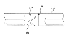
본원에서 기재한 실시형태는 또한 본원에서 기재한 인공 판막(100) 실시형태의 제조 방법에 관련되어 있다. 다양한 실시형태를 제조하기 위해, 원통 맨드릴(710)이 사용될 수 있다. 도 5에 관해, 맨드릴(710)은 첨판 프레임(130)을 위에 수용하도록 조작가능한 구조 형태를 포함한다.The embodiments described herein also relate to a method of making the
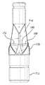
본원에서 기재한 실시형태는 또한 본원에서 기재한 인공 판막(100) 실시형태의 제조 방법에 관련된다. 다양한 실시형태를 제조하기 위해, 원통 맨드릴(710)이 사용될 수 있다. 도 5에 관해, 맨드릴(710)은 첨판 프레임(130)을 위에 수용하도록 조작가능한 구조 형태를 포함한다. 인공 판막(100)의 제조 방법에 대한 실시형태는 필름(160)의 제1 층, 예를 들어 본원에서 기재한 복합체를 맨드릴(710) 주위에 관 형태로 감싸는 단계; 도 5에 도시한 바와 같이, 첨판 프레임(130)을 필름(160)의 제1 층 위에 배치하는 단계; 필름(160)의 제2 층을 첨판 프레임(130) 위에 형성하는 단계; 어셈블리를 열로 고정하는 단계; 도 6a와 6b에 도시한 바와 같이 어셈블리를 절삭 맨드릴(712) 위에 수용하는 단계; 첨판 윈도(137) 내에서 첨판 윈도 톱을 가로질러 필름(160)을 잘라내어 도 2a 및 2b의 인공 판막(100)을 얻는 단계를 포함한다. 도 2a 및 2b에서, 첨판(140)은 이들이 절삭 맨드릴(712)에 의해 수용될 때처럼 약간 열려서 도시되어 있다. 완전히 폐쇄된 인공 판막(100)은 삼중점(148)을 포함하여, 하류 혈액이 판막을 통해 역류하는 것을 방지하도록 판막을 폐쇄하게 하는 하류 유체 압력의 영향 하에 접합하도록 합치는 첨판들(140)의 첨판 자유 에지들(142)을 가질 것이라고 이해된다.The embodiments described herein also relate to a method of making the
실시예Example
일예의 실시형태에서, 발포 불소중합체 막과 엘라스토머 물질을 가진 복합 재료로부터 형성되고, 반강성, 접힐 수 없는 금속 프레임에 접합한 중합체 첨판을 갖고, 추가로 스트레인 릴리프(strain relief)를 가진 심장 판막을 하기 공정에 따라 구성하였다:In one exemplary embodiment, a heart valve having a polymeric tip formed from a composite material having a foamed fluoropolymer film and an elastomeric material and joined to a semi-rigid, non-collapsible metal frame, further comprising a heart valve having a strain relief Was constructed according to the following procedure:
외부 직경이 26.0 mm이고, 벽 두께가 0.6 mm인 단단하게 강화된 일정 길이의 MP35N 코발트 크롬 튜브로부터 판막 프레임을 레이저 기계 가공하였다. 프레임을 전기 연마하여 각 표면으로부터 0.0126 mm의 물질 제거하였고, 에지를 둥글게 남겼다. 프레임을 조면 처리 단계에 노출시켜 프레임에 대한 첨판의 접착성을 향상시켰다. 아세톤의 초음파 조에서 대략 5분간 함침에 의해 프레임을 세정하였다. 그 후 당업자에게 통상 알려진 설비(예, 플라즈마 펜(Plasma Pen), 피브이에이 테플라 어메리카사(PVA TePLa America, Inc, 캘리포니아 코로나)) 및 방법을 사용하여 전체 금속 프레임 표면에 플라즈마 처리하였다. 이러한 처리는 또한 불소화 에틸렌 프로필렌(FEP) 접착제의 습윤화를 향상시키는 역할을 하였다.The valve frame was laser machined from a tightly reinforced constant length MP35N cobalt chrome tube having an outer diameter of 26.0 mm and a wall thickness of 0.6 mm. The frame was electro-polished to remove 0.0126 mm of material from each surface, leaving the edges rounded. When the frame is roughened, it is exposed to the processing step to improve the adhesion of the plate to the frame. The frame was cleaned by impregnation in an ultrasonic bath of acetone for approximately 5 minutes. The entire metal frame surface was then plasma treated using equipment known to those skilled in the art (e.g., Plasma Pen, PVA Tepla America, Inc., Corona, Calif.) And method. This treatment also served to improve the wetting of the fluorinated ethylene propylene (FEP) adhesive.
그 후 FEP 분말(다이킨 어메리카, 뉴욕주 오렌지버그)을 프레임에 도포하였다. 더 구체적으로는, FEP 분말을 교반하여 밀폐 블렌딩 장치, 예컨대 표준 주방형 블렌더에서 비산 "구름"을 형성하였고, 이와 동시에 프레임을 구름에 현탁시킨다. 분말 층이 프레임의 전체 표면에 부착될 때까지 프레임을 FEP 분말 구름에 노출시켰다. 그 후 프레임을 320℃에 설정된 강제 공기 오븐에 대략 3분간 둠으로써 이를 열처리하였다. 이로써 전체 프레임 위에 얇은 코팅으로서 분말이 용융하여 부착되게 하였다. 프레임을 오븐에서 꺼내 방치하여 대략 실온으로 냉각시켰다.FEP powder (Daikin America, New York, Orangeburg) was then applied to the frame. More specifically, the FEP powder is stirred to form a scattering "cloud" in a closed blending apparatus, such as a standard kitchen blender, while at the same time suspending the frame in the cloud. The frame was exposed to the FEP powder cloud until the powder layer adhered to the entire surface of the frame. The frame was then heat treated by placing it in a forced air oven set at 320 DEG C for approximately 3 minutes. This allowed the powder to melt and adhere as a thin coating over the entire frame. The frame was removed from the oven and allowed to cool to approximately room temperature.
중합체 스트레인 릴리프를 하기 방식으로 프레임에 부착하였다. 얇은(122 ㎛) 벽이 있는 소결된 15 mm 직경 ePTFE 튜브를 경사진 맨드릴 위에 방사상으로 신장함으로써 24.5 mm 통기식 금속 맨드릴 위에 배치하였다. 연속 FEP 코팅이 있는 실질적으로 비다공성 ePTFE 막 2 층을 맨드릴 쪽 FEP 측면이 있는 맨드릴에 원주로 감쌌다. 감싼 맨드릴을 320℃로 설정한 대류 오븐에 놓고, 20분간 가열하고, 실온으로 공랭시켰다. ePTFE와 실질적으로 비다공성 ePTFE 막을 결합하여 내부 이형 라이너로서 역할을 하였고, 외과용 메스 블레이드를 사용하여 천공하여 통기구와 맨드릴 사이의 압력을 전달하였다. 이러한 전체 이형 라이너를 이후 단계에서 제거한다.The polymeric strain relief was attached to the frame in the following manner. A sintered 15 mm diameter ePTFE tube with a thin (122 mu m) wall was placed on a 24.5 mm ventilated metal mandrel by radial extension on a sloped mandrel. Two layers of substantially non-porous ePTFE membrane with continuous FEP coating were wrapped circumferentially in a mandrel with a mandrel side FEP side. The wrapped mandrel was placed in a convection oven set at 320 DEG C, heated for 20 minutes, and air-cooled to room temperature. The combination of ePTFE and a substantially non-porous ePTFE membrane served as an internal release liner and perforated using a surgical scalpel to deliver pressure between the vent and the mandrel. This entire release liner is removed at a later stage.
5 cm 길이의 두꺼운(990 μ) 벽이 있는 부분적으로 소결된 22 mm 내부 직경 ePTFE 튜브(밀도 = 0.3 g/㎤)를 이형 라이너가 있는 24.5 mm 통기식 금속 맨드릴에 배치하였다. 경사진 맨드릴에 튜브를 연신시킴으로써 ePTFE 튜브 내경을 확대시켜 더 큰 맨드릴 직경을 수용하였다.A partially sintered 22 mm inner diameter ePTFE tube (density = 0.3 g / cm3) with a 5 cm thick (990 mu) wall was placed in a 24.5 mm vented metal mandrel with a release liner. By extending the tube into the inclined mandrel, the bore diameter of the ePTFE tube was enlarged to accommodate a larger mandrel diameter.
용융 압출과 연신을 사용하여 1형 FEP(ASTM D3368)의 얇은(4 ㎛) 필름을 구성하였다. FEP 1 층을 5 cm 길이의 ePTFE 튜브에 감쌌다.A thin (4 탆) film of 1 type FEP (ASTM D3368) was constructed using melt extrusion and stretching. One layer of FEP was wrapped in a 5 cm long ePTFE tube.
FEP 분말 코팅된 프레임을 일반적으로 ePTFE 튜브와 FEP 필름의 5 cm 폭(span)의 중간에 통기식 금속 맨드릴 상에 배치하였다.The FEP powder coated frame was placed on a ventilated metal mandrel, generally between the ePTFE tube and a 5 cm span of the FEP film.
FEP 1 층을 프레임과 5 cm 길이의 ePTFE 튜브 위에 감쌌다.One layer of FEP was wrapped over a frame and a 5 cm long ePTFE tube.
제2의 5 cm 길이의 990 ㎛ 두께/22 mm 내경 ePTFE 튜브를 그의 반경을 경사진 맨드릴 위에서 연신시킴으로써 24.5 mm 통기식 금속 맨드릴 상에 층을 이룬 어셈블리에 배치하여 더 큰 구조물 직경을 수용하였다.A second 5 cm long 990 um thick / 22 mm inner diameter ePTFE tube was placed in a layered assembly on a 24.5 mm vented metal mandrel by stretching it over its radius mandrel mandrel to accommodate a larger structure diameter.
실질적으로 비다공성인 ePTFE 막을 구조물보다 더 큰 직경에서 원통으로 구성하여, 희생 튜브로서 언급된 어셈블리 위에 놓았다. 맨드릴에 대해 희생 튜브의 양쪽 단부를 밀봉하는데 소결된 ePTFE 섬유(예 Gore® Rastex® 바느질 실, 부품 번호 S024T2, 델라웨어주 뉴와크)를 사용하였다.A substantially non-porous ePTFE membrane was constructed of a cylinder with a larger diameter than the structure and placed on the assembly referred to as the sacrificial tube. Sintered ePTFE fibers (eg, Gore® Rastex® sewing thread, part number S024T2, Newark, DE) were used to seal both ends of the sacrificial tube against the mandrel.
상기에 기재한 희생 튜브 외부에 100 psi의 공기압을 가할 수 있는 대류 오븐(390℃의 온도 설정점)에서 맨드릴 내부에 진공을 유지하면서 맨드릴을 포함하여, 어셈블리를 가열하였다. 맨드릴 온도가 대략 360℃에 도달하도록(맨드릴 내경과 직접 접촉하는 열전대에 의해 측정됨) 어셈블리를 40분간 가열하였다. 어셈블리를 오븐으로부터 빼내서 아직 100 psi 압력 및 진공 하에 대략 실온으로 냉각시켰다.The assembly was heated, including the mandrel, while maintaining a vacuum inside the mandrel at a convection oven (temperature set point of 390 DEG C) capable of applying an air pressure of 100 psi outside the sacrificial tube described above. The assembly was heated for 40 minutes so that the mandrel temperature reached approximately 360 ° C (as measured by a thermocouple in direct contact with the mandrel inner diameter). The assembly was removed from the oven and still cooled to approximately room temperature under 100 psi pressure and vacuum.
그 후 Rastex® 섬유와 희생 튜브를 제거하였다. 대략 30 psi의 압력을 맨드릴의 내경에 가해 어셈블리를 빼내는데 도움을 주었다. 라이너를 뒤집고, 이것을 축 방향으로 떨어져 당김으로써 내부 이형 라이너를 어셈블리의 내경에서 떨어져서 벗겨냈다.Rastex® fibers and sacrificial tubes were then removed. A pressure of about 30 psi was applied to the mandrel bore to help pull the assembly out. By turning the liner up and pulling it apart in the axial direction, the inner release liner was stripped away from the inner diameter of the assembly.
과량의 중합체 물질을 외과용 메스로 잘라내고, 첨판 윈도와 프레임의 하부로부터 제거하여 대략 0.5 내지 1.0 mm의 물질 돌출부(overhang)를 남겼다.Excess polymer material was cut into surgical scalpels and removed from the bottom of the tip window and frame to leave a material overhang of approximately 0.5 to 1.0 mm.
그 후 첨판 재료를 제조하였다. 미국특허 제7,306,729호에 기재된 일반 내용에 따라 ePTFE의 막을 제조하였다. ePTFE 막은 면적당 질량이 0.452 g/㎡, 두께가 약 508 nm, 매트릭스 인장 강도가 종 방향에서 705 MPa 및 횡 방향에서 385 MPa이었다. 이 막에 플루오로엘라스토머를 흡수시켰다. 공중합체는 실질적으로 약 65 내지 70 중량%의 퍼플루오로메틸 비닐 에테르 및 보충적으로 약 35 내지 30 중량%의 테트라플루오로에틸렌으로 이루어진다.Thereafter, a leaf material was prepared. Membranes of ePTFE were prepared according to the general contents described in U.S. Patent No. 7,306,729. The ePTFE membrane had a mass per unit area of 0.452 g /
플루오로엘라스토머를 Novec HFE7500(3M, 미네소타 세인트 파울)에 2.5% 농도로 용해시켰다. 메이어 바를 사용하여 용액을 ePTFE 막에 코팅하였고(폴리프로필렌 이형 필름에 의해 지지되면서), 145℃로 설정된 대류 오븐에서 30초간 건조시켰다. 2 단계의 코팅 후에, 최종 ePTFE/플루오로엘라스토머 또는 복합체는 1.75 g/㎡의 면적당 질량, 29.3 중량%의 불소중합체, 약 8.6 KPa의 돔(dome) 파열 강도, 및 0.81 ㎛의 두께를 가졌다.The fluoroelastomer was dissolved in Novec HFE7500 (3M, St. Paul, Minn.) At a concentration of 2.5%. The solution was coated on the ePTFE membrane (supported by a polypropylene release film) using a Meyer bar and dried in a convection oven set at 145 캜 for 30 seconds. After the two-step coating, the final ePTFE / fluoroelastomer or composite had a mass per area of 1.75 g /
그 후 스트레인 릴리프를 한정하는 중합체 물질로 캡슐화된 프레임을 첨판 재료에 원통 또는 관 형상으로 다음 방식으로 부착하였다. 이형 라이너를 24.5 mm 통기식 맨드릴에 배치하였고, 외과용 메스 블레이드를 사용하여 천공하여 맨드릴 내 통기구 사이의 압력을 전달하였다.The frame encapsulated with a polymeric material defining the strain relief was then attached to the ply material in cylindrical or tubular form in the following manner. The release liner was placed in a 24.5 mm ventilated mandrel and punctured using a surgical scalpel to deliver pressure between the vents in the mandrel.
맨드릴의 100 cm 폭의 중간에 일반적으로 통기식 금속 맨드릴을 덮는 이형 라이너 상에 중합체 스트레인 릴리프가 있는 프레임을 배치하였다.A frame with polymeric strain relief was placed on a release liner that typically covered a ventilated metal mandrel in the middle of a 100 cm wide mandrel.
62 층의 첨판 재료를 프레임과 100 cm 길이의 맨드릴 위에 감쌌다. 통기구에 인접한 맨드릴로부터 외과용 메스로서 과량의 첨판 재료를 잘라 냈다.62 layers of plywood material were wrapped on a frame and a 100 cm long mandrel. The excess ply material was cut out as a surgical scalpel from the mandrel adjacent to the vent.
희생 튜브를 어셈블리 위에 놓고, 맨드릴에 대해 희생 튜브의 양 단부를 밀봉하는데 Rastex® 섬유를 사용하였다.A sacrificial tube was placed over the assembly and Rastex® fibers were used to seal both ends of the sacrificial tube relative to the mandrel.
상기에 기재한 희생 튜브 외부에 100 psi의 공기압을 가할 수 있는 대류 오븐(390℃의 온도 설정점)에서 맨드릴 내부에 진공을 유지하면서 맨드릴을 포함하여, 어셈블리를 가열하였다. 맨드릴 온도가 대략 285℃에 도달하도록(맨드릴 내경과 직접 접촉하는 열전대에 의해 측정됨) 어셈블리를 23분간 가열하였다. 어셈블리를 오븐으로부터 빼내서 아직 100 psi 압력 및 진공 하에 대략 실온으로 냉각시켰다.The assembly was heated, including the mandrel, while maintaining a vacuum inside the mandrel at a convection oven (temperature set point of 390 DEG C) capable of applying an air pressure of 100 psi outside the sacrificial tube described above. The assembly was heated for 23 minutes so that the mandrel temperature reached approximately 285 DEG C (as measured by a thermocouple in direct contact with the mandrel inner diameter). The assembly was removed from the oven and still cooled to approximately room temperature under 100 psi pressure and vacuum.
그 후 Rastex® 섬유 및 희생 튜브를 제거하였다. 대략 30 psi의 압력을 맨드릴 내부에 가해 어셈블리를 빼내는데 도움을 주었다. 라이너를 뒤집고, 이것을 축 방향으로 떨어져 당김으로써 내부 이형 라이너를 어셈블리의 내경에서 떨어져서 벗겨냈다.The Rastex® fiber and sacrificial tube were then removed. A pressure of about 30 psi was applied inside the mandrel to help remove the assembly. By turning the liner up and pulling it apart in the axial direction, the inner release liner was stripped away from the inner diameter of the assembly.
그 후 원통 형상의 프레임과 첨판 어셈블리를 다음 방식으로 최종 폐쇄된 첨판 기하 구조로 성형하였다. 어셈블리를 첨판의 폐쇄 기하 구조를 한정하는 공극이 있는 24.5 mm 통기식 맨드릴 상에 배치하였다.The cylindrical frame and the pivot assembly were then formed into a final closed pillar geometry in the following manner. The assembly was placed on a 24.5 mm vented mandrel with pores defining the closed geometry of the tip.
맨드릴 내 원주 그루브에 대해 첨판 튜브의 양 단부를 밀봉하는데 Rastex® 섬유를 사용하였다.Rastex® fibers were used to seal both ends of the shank tube for circumferential grooves in the mandrel.
상기에 기재한 희생 튜브 외부에 100 psi의 공기압을 가할 수 있는 대류 오븐(390℃의 온도 설정점)에서 맨드릴 내부에 진공을 유지하면서 맨드릴을 포함하여, 어셈블리를 가열하였다. 맨드릴 온도가 대략 285℃에 도달하도록(맨드릴 내경과 직접 접촉하는 열전대에 의해 측정됨) 어셈블리를 23분간 가열하였다. 어셈블리를 오븐으로부터 빼내서 아직 100 psi 압력 및 진공 하에 대략 실온으로 냉각시켰다. 그 후 Rastex® 섬유를 제거하고, 대략 10 psi의 압력을 맨드릴의 내경에 가해 어셈블리를 빼내는데 도움을 주었다.The assembly was heated, including the mandrel, while maintaining a vacuum inside the mandrel at a convection oven (temperature set point of 390 DEG C) capable of applying an air pressure of 100 psi outside the sacrificial tube described above. The assembly was heated for 23 minutes so that the mandrel temperature reached approximately 285 DEG C (as measured by a thermocouple in direct contact with the mandrel inner diameter). The assembly was removed from the oven and still cooled to approximately room temperature under 100 psi pressure and vacuum. The Rastex® fiber was then removed and a pressure of approximately 10 psi was applied to the mandrel bore to help remove the assembly.
일반적으로 도 6a와 6b에 도시한 절삭 맨드릴(712)의 공극 몰드(714)에 도시한 자유 에지 선을 따라 과량의 첨판 재료를 잘라 냈다.Excess ply material is typically cut along the free edge lines shown in the
최종 첨판은 두께가 50.3 ㎛인 28.22 중량%의 불소중합체로 이루어졌다. 각 첨판은 복합체가 62 층이었고, 두께/층수의 비가 0.81 ㎛이었다.The final tip was composed of 28.22 wt% fluoropolymer with a thickness of 50.3 탆. Each plate had a composite of 62 layers and a ratio of thickness / number of layers of 0.81 탆.
얻어진 인공 판막(100)은 도 2a-2d에 도시한 바와 같이, 다수의 세공을 갖는 1개 초과의 불소중합체 층과 1개 초과의 불소중합체 층의 실질적으로 모든 세공 내에 존재하는 엘라스토머가 있는 복합 재료로부터 형성되는 첨판(140)을 포함한다. 각 첨판(104)은 도 2d에 도시한, 혈액이 판막 어셈블리를 통해 흐르는 것이 실질적으로 방지되는 폐쇄 위치 및 도 2c에 도시한, 혈액이 판막 어셈블리를 통해 흐르게 하는 개방 위치 사이에서 이동가능하다. 따라서 인공 판막(100)의 첨판(104)은 일반적으로 인간 환자의 혈류 방향을 조절하는 개폐 위치 사이에 순환한다.The resultant
유체역학적 성능을 가속 마모 시험 전에 측정하였다. 성능 값은 EOA = 2.4 ㎠ 및 역류 분획 = 11.94%이었다.The hydrodynamic performance was measured before the accelerated wear test. The performance values were EOA = 2.4 ㎠ and backflow fraction = 11.94%.
판막 첨판의 성능은 판막 전체에 걸쳐 전형적인 해부학적 압력과 플로를 측정하는 실시간 맥박 복제기(pulse duplicator)에서 특성화하였다. 플로 성능은 하기 공정을 특징으로 하였다:The performance of the valve plate was characterized in a real-time pulse duplicator measuring typical anatomical pressure and flow throughout the valve. Flow performance was characterized by the following process:
판막 어셈블리를 실리콘 환상형 고리(지지 구조체)에 넣어(potted) 판막 어셈블리가 실시간 맥박 복제기에서 후속으로 평가되게 하였다. 맥박 복제기 제조사(비비트로 라보라토리즈사(ViVitro Laboratories, Inc., 캐나다 빅토리아 비씨))의 제안에 따라 포팅(potting) 공정을 수행하였다.The valve assembly was potted into a silicone annular ring (support structure) allowing the valve assembly to be subsequently evaluated in a real time pulse replicator. A potting process was performed according to the proposal from a pulse reporter manufacturer (ViVitro Laboratories, Inc. Victoria BC, Canada).
그 후 포팅된 판막 어셈블리를 실시간 좌측 심장 플로 맥박 복제기 시스템에 넣었다. 플로 맥박 복제기 시스템은 브이에스아이 비비트로 시스템즈사(VSI Vivitro Systems Inc., 캐나다 빅토리아 비씨)가 공급한 하기 구성 요소를 포함하였다: 슈퍼 펌프(Super Pump, Servo Power Amplifier Part Number SPA 3891); 슈퍼 펌프 헤드(Super Pump Head, Part Number SPH 5891 B, 38.320 ㎠ 실린더 면적; 판막 스테이션(station)/고정장치; 파형 발생기(TriPack 부품번호 TP 2001); 센서 인터페이스(Sensor Interface, 부품번호 VB 2004); 센서 증폭기 부품(부품번호 AM 9991); 및 직사각형파 전자기 플로 미터(Carolina Medical Electronics Inc., 미국 노스캐롤라이나주 이스트 벤드).The ported valve assembly was then inserted into a real-time left-sided cardiac flow pulse replicator system. The flow pulse replicator system included the following components supplied by VSI Vivitro Systems Inc., Victoria BC, Canada: Super Pump (Servo Power Amplifier Part Number SPA 3891); Super Pump Head, Part Number SPH 5891 B, 38.320 ㎠ Cylinder Area, Valve Station / Fixture, Waveform Generator (TriPack part number TP 2001), Sensor interface (part number VB 2004); Sensor amplifier parts (part number AM 9991); and rectangular wave electromagnetic flowmeters (Carolina Medical Electronics Inc., East Bend, NC).
일반적으로, 플로 맥박 복제기 시스템은 정용량형 피스톤 펌프를 사용하여 시험 중인 판막을 통한 원하는 유체 플로를 생성한다.Generally, a flow pulsator system uses a constant capacity piston pump to produce the desired fluid flow through the valve under test.
심장 플로 맥박 복제기 시스템은 원하는 플로(5 L/min), 평균 압력(15 mmHg), 및 모의 맥박수(70 bpm)를 나타내도록 조정되었다. 그 후 시험 중인 판막을 약 5 내지 20분간 순환시켰다.The cardiac flow pulsator system was adjusted to exhibit the desired flow (5 L / min), mean pressure (15 mmHg), and simulated heart rate (70 bpm). The valve under test was then circulated for about 5 to 20 minutes.
우심실 압력, 폐 압력, 유량, 및 펌프 피스톤 위치를 포함하여, 시험기간 중 압력과 플로 데이터를 측정하고, 수집하였다. 판막을 특성화하는데 사용된 변수는 유효 오리피스 면적과 역류 분획이다. 유효 오리피스 면적(EOA, effective orifice area)은 다음과 같이 계산될 수 있다: EOA(㎠) = Qrms/(51.6*(ΔP)1/2), 여기서 Qrms는 평균 제곱근 심장 수축/심장 확장 유량(㎤/s)이고, ΔP는 평균 심장 수축/심장 확장 압력 강하(mmHg)이다.Pressure and flow data were measured and collected during the study period, including right ventricular pressure, lung pressure, flow rate, and pump piston position. The variables used to characterize the valve are the effective orifice area and the countercurrent flow fraction. The effective orifice area (EOA) can be calculated as follows: EOA (cm 2) = Q rms /(51.6*(P) 1/2 ), where Qrms is the mean square root contraction /
판막의 유체역학적 성능의 또 다른 측정치는 역류 분획이며, 이는 박출량으로 나눈 판막을 통해 역류한 유체 또는 혈액의 양이다.Another measure of the hydrodynamic performance of a valve is the reflux fraction, which is the amount of fluid or blood that has flowed back through the valve divided by the output.
본원에서 사용되는 바와 같이, 단위 ㎡/g로 표시되는 단위 질량당 표면적은 Coulter SA3100 가스 흡착 분석기(베크만 콜터사(Beckman Coulter Inc.) 미국 캘리포니아 풀러톤) 상에서 브루나우어 엠멧 텔러(Brunauer-Emmett-Teller(BET)) 방법을 사용하여 측정되었다. 측정을 수행하기 위해, 발포 불소중합체 막의 중앙에서 샘플을 잘라서 작은 샘플 튜브에 넣었다. 샘플의 질량은 대략 0.1 내지 0.2 g이었다. 튜브를 베크만 콜터사제 Coulter SA-Prep 표면적 가스방출기(모델 SA-Prep, P/n 5102014)에 넣고, 약 110℃에서 약 2 시간 동안 헬륨으로 퍼지하였다. 그 후 샘플 튜브를 SA-Prep 가스방출기로부터 빼내 칭량하였다. 그 후 샘플 튜브를 SA3100 가스 흡착 분석기에 넣고, 자유 공간을 계산하는데 헬륨을 사용하고, 흡착질 가스로서 질소를 사용하여 기구 설명서에 따라 BET 표면적 분석을 수행하였다.As used herein, the surface area per unit mass expressed in units < RTI ID = 0.0 > m2 / g < / RTI > is measured using a Coulter SA3100 gas adsorption analyzer (Beckman Coulter Inc., Fullerton, Teller (BET)) method. To perform the measurement, a sample was cut from the center of the foamed fluoropolymer membrane and placed in a small sample tube. The mass of the sample was approximately 0.1 to 0.2 g. The tube was placed in a Beckman Coulter Coulter SA-Prep surface gas emitter (model SA-Prep, P / n 5102014) and purged with helium at about 110 ° C for about 2 hours. The sample tube was then removed from the SA-Prep gas emitter and weighed. The sample tube was then placed in an SA3100 gas adsorption analyzer, BET surface area analysis was performed according to instrumental instructions using helium to calculate free space and nitrogen as adsorbent gas.
포러스 머티어리얼즈사(Porous Materials, Inc.)(미국 뉴욕 이타카)제 모세관 플로 포로미터(porometer), 모델 CFP 1500AEXL을 사용하여 ASTM F31 6-03의 일반적 내용에 따라 포점과 평균 플로 세공 크기(flow pore size)를 측정하였다. 샘플 막을 샘플 챔버에 넣고, 표면장력이 약 20.1 다인/cm인 SilWick 실리콘 유체(포러스 머티어리얼즈사로부터 입수가능)로 습윤화하였다. 샘플 챔버의 하부 클램프에 약 2.54 cm 직경의 구멍이 있었다. 이소프로필 알코올을 시험 유체로서 사용하였다. 캅윈(Capwin) 소프트웨어 버전 7.73.012를 사용하여 하기 표에 규정된 바와 같이 하기 변수를 설정하였다. 본원에서 사용되는 바와 같이, 평균 플로 세공 크기와 세공 크기는 상호교환하여 사용된다.Using a capillary porometer, model CFP 1500AEXL from Porous Materials, Inc. (Ithaca, New York, USA), the porosity and average flow size (flow) according to the general contents of ASTM F31 6-03 pore size) were measured. The sample membrane was placed in a sample chamber and wetted with a SilWick silicone fluid (available from Porous Material's Co.) having a surface tension of about 20.1 dynes / cm. The lower clamp of the sample chamber had a hole of about 2.54 cm diameter. Isopropyl alcohol was used as the test fluid. Capwin software version 7.73.012 was used to set the following variables as specified in the table below. As used herein, the average flow pore size and pore size are used interchangeably.
변수 설정값variable Setting value
맥스플로(Maxflow)(㎤/m) 200000Maxflow (cm < 3 > / m) 200000
버블플로(Bublflow)(㎤/m) 100Bublflow (cm3 / m) 100
F/PT(올드 버블타임, old bubltime) 50F / PT (old bubble time, old bubltime) 50
민비프레스(Minbpress)(PSI) 0Minbpress (PSI) 0
제로타임(Zerotime)(초) 1Zero time (seconds) One
V2incr(cts) 10V2incr (cts) 10
프레그인크(Preginc)(cts) 1Preginc (cts) One
펄스 지연(초) 2Pulse delay (seconds) 2
맥스프리(Maxpre)(PSI) 500Maxpre (PSI) 500
펄스 폭(초) 0.2Pulse width (seconds) 0.2
미넥타임(Mineqtime)(초) 30Mineqtime (seconds) 30
프레슬루(Presslew)(cts) 10Presslew (cts) 10
플로슬루(Flowslew)(cts) 50Flowslew (cts) 50
이키터(Eqiter)
3
아베이터(Aveiter) 20Aveiter 20
맥스피디프(Maxpdif)(PSI) 0.1Maxpdif (PSI) 0.1
맥스에프디프(Maxfdif)(PSI) 50Maxfdif (PSI) 50
사르트피(Sartp)(PSI) 1Sartp (PSI) One
사르트에프(Sartf)(㎤/m) 500Sartf (cm < 3 > / m) 500
Kaefer FZ1000/30 두께 스냅 게이지(snap gauge)(케이퍼 메슈렌파브릭사(Kaefer Messuhrenfabrik GmbH, 독일 빌링겐 슈벤닝겐)의 2개 플레이트 사이에 막을 넣음으로써 막 두께를 측정하였다. 3회 측정치의 평균을 기록하였다.The film thickness was measured by placing a membrane between two plates of a Kaefer FZ1000 / 30 thickness gauge (Kaefer Messuhrenfabrik GmbH, Billingen Schwenningen, Germany). The average of the three measurements .
당업자에게 알려진 여러 방법, 예컨대 표면 및/또는 단면 외관, 또는 다른 분석에 의해 세공 내에 엘라스토머의 존재를 확인할 수 있다. 이들 분석을 첨판으로부터 엘라스토머의 제거 전 및 후에 실시할 수 있다.The presence of the elastomer in the pores can be confirmed by various methods known to those skilled in the art, such as surface and / or cross-sectional appearance, or other analysis. These analyzes can be carried out before and after the removal of the elastomer from the blade.
막 샘플을 다이 절단하여 약 2.54 cm x 약 15.24 cm의 직사각형 섹션을 형성하고, 중량(메틀러 톨레도(Mettler-Toledo) 분석 저울 모델 AG204 사용) 및 두께(케이퍼 Fz1000/30 스냅 게이지 사용)를 측정하였다. 이들 데이터를 사용하여, 다음 식으로 밀도를 산출하였다: ρ=m/w*l*t, 여기서 ρ=밀도(g/㎤), m=질량(g), w=폭(cm), l=길이(cm), 및 t=두께(cm). 3회 측정치의 평균을 기록하였다.Membrane samples were die cut to form a rectangular section of approximately 2.54 cm x approximately 15.24 cm, and weighed (using a Mettler-Toledo analytical balance model AG204) and thickness (using a capillary Fz 1000/30 snap gauge) Respectively. Using these data, the density was calculated by the following equation: ρ = m / w * 1 * t where ρ = density (g / cm 3), m = mass (g), w = Length (cm), and t = thickness (cm). The average of three measurements was recorded.
평면(flat-faced) 그립과 0.445 kN 로드 셀(load cell)이 장착된 INSTRON 122 인장 시험기를 사용하여 인장 파괴 하중을 측정하였다. 게이지 길이는 약 5.08 cm이었고, 크로스헤드(cross-head) 속도는 약 50.8 cm/min이었다. 샘플 치수는 약 2.54 cm x 약 15.24 cm이었다. 종 방향 측정을 위해, 더 긴 치수의 샘플을 최고 강도 방향으로 배향하였다. 직각 MTS 측정을 위해, 더 큰 치수의 샘플을 최고 강도 방향에 수직으로 배향하였다. 메틀러 톨레도 스케일 모델 AG204를 사용하여 각 샘플을 칭량한 다음, 케이퍼 FZ1000/30 스냅 게이지를 사용하여 두께를 측정하였다. 그 후 샘플을 개별적으로 인장 시험기에서 시험하였다. 각 샘플 중 3개의 상이한 섹션을 측정하였다. 3개의 최대 하중(즉, 피크력) 측정치의 평균을 기록하였다. 다음 등식을 사용하여 종 방향 및 횡 방향 매트릭스 인장 강도(MTS, matrix tensile strength)를 산출하였다: MTS = (최대 하중/단면적)*(PTFE의 벌크 밀도)/(다공성 막의 밀도), 여기서 PTFE의 벌크 밀도는 약 2.2 g/㎤인 것으로 취했다. ASTM D790에 제시된 일반 과정을 따름으로써 굽힘 강성을 측정하였다. 큰 시편을 이용할 수 없다면, 시편을 축소해야 한다. 시험 조건은 다음과 같았다. 서로 약 5.08 mm 수평으로 배치한 예리한(sharp) 기둥을 사용하는 3점 굽힘 시험 장치에서 첨판 시편을 측정하였다. 약 80 mg의 무게가 나가는 약 1.34 mm 직경의 스틸 바를 y(아래쪽) 방향에 편향을 야기하는데 사용하였고, 시편을 x 방향에서 제약하지 않았다. 스틸 바를 막 시편의 중앙 점에 천천히 위치시켰다. 약 5분간 대기한 후, y 편향을 측정하였다. 상기와 같이 지지된 탄성 빔의 편향을 d = F*L3/48*El로 표시할 수 있으며, 여기서 F(뉴톤으로)는 빔 길이(L(미터))의 중앙에 가한 하중이고, 따라서 L = 서스펜딩 기둥 사이의 1/2 거리이며, El 은 굽힙 강성(Nm)이다. 이러한 관계식으로부터 El의 값을 산출할 수 있다. 직사각형 단면에 대해: I = t3*w/12, 여기서 I = 단면 관성 모멘트, t = 시편 두께(미터), w = 시편 폭(미터). 이러한 관계식에 의해, 굽힘 편향의 측정 범위에 걸쳐 평균 탄성률을 산출할 수 있다.Tensile failure loads were measured using an
해당 기술 분야의 당업자면, 다양한 변형예와 변경예가 본 실시형태에서 실시형태의 기술적 상 또는 범위를 벗어나는 일 없이 이루어질 수 있다는 점을 명백히 이해할 수 있을 것이다. 따라서 본 실시형태들은 이들의 청구범위와 이의 균등물의 범위 내에 있다면 본 발명의 변형예 및 변경예를 포괄하는 것으로 의도된다.
Those skilled in the art will appreciate that various modifications and changes may be made without departing from the spirit or scope of the embodiments in this embodiment. It is therefore intended that the present embodiments cover modifications and variations of this invention provided they fall within the scope of the appended claims and their equivalents.
Claims (28)
첨판 프레임(leaflet frame); 및
첨판 프레임에 결합된 다수의 첨판을 포함하며, 각 첨판은 첨판 자유 에지와 첨판 베이스를 포함하고, 각 첨판의 첨판 베이스는 절단되고(truncated), 여기서 첨판은 단면상 첨판 프레임 상의 알파 평면(alpha plane)에서 선을 나타내는 것인 인공 판막.As a prosthetic valve,
Leaflet frame; And
Wherein each blade comprises a blade free edge and a blade base, and the blade base of each blade is truncated, wherein the blade comprises an alpha plane on the blade frame in cross section, Of the prosthetic valve.
첨판 프레임에 결합되고 첨판 윈도 각각으로부터 연장되는 하나 이상의 첨판을 한정하는 필름을 포함하며, 각 첨판은 2개의 첨판 측면(leaflet side), 첨판 베이스(leaflet base) 및 첨판 베이스 맞은편의 첨판 자유 에지(leaflet free edge)를 가진 이등변 사각형 형상을 실질적으로 가지며, 2개의 첨판 측면은 첨판 베이스로부터 분기하며, 첨판 베이스는 실질적으로 평편하고, 첨판 베이스는 윈도 베이스에 결합되며, 2개의 첨판 측면 각각은 2개의 첨판 윈도 사이드 중 하나에 결합되는 것인 인공 판막.A sill frame according to claim 1, wherein the sill frame has a generally tubular shape and defines a plurality of sill windows, each of the sill windows having two leaflet window side, leaflet window base, A leaflet window top; And
A film coupled to the leaf frame and defining one or more leaflets extending from each leaflet window, each leaflet having two leaflet sides, a leaflet base, and a leaflet- free edge, the two prismatic sides diverging from the prismatic base, the prismatic base being substantially flat, the prismatic base being coupled to the window base, each of the two prismatic sides having two prismatic sides, A prosthetic valve that is coupled to one of the windowsides.
일반적인 관 형상을 갖는 첨판 프레임을 제공하는 단계로서, 첨판 프레임은 다수의 첨판 윈도를 한정하며, 첨판 윈도 각각은 2개의 첨판 윈도 사이드, 첨판 윈도 베이스, 및 첨판 윈도 톱을 포함하는 것인 단계;
필름을 제공하는 단계;
필름의 1개 초과 층을 첨판 윈도 각각으로부터 연장되는 하나 이상의 첨판을 한정하는 필름의 추가 층과 접촉시키면서 첨판 프레임 주위에 필름을 감싸는(wrapping) 단계로서, 각 첨판은 2개의 첨판 측면, 첨판 베이스 및 첨판 베이스 맞은편의 자유 에지를 가진 이등변 사각형 형상을 실질적으로 가지며, 2개의 첨판 측면은 첨판 베이스로부터 분기하고, 첨판 베이스는 실질적으로 평편하고, 첨판 베이스는 원도 베이스에 결합되며, 2개의 첨판 측면 각각은 일반적인 환상 지지체 구조를 제공하는 2개의 첨판 윈도 사이드 중 하나에 결합되는 것인 단계; 및
필름의 층들을 자체에 그리고 첨판 프레임에 접착시키는 단계를 포함하는 인공 심장 판막의 형성 방법.As a method for forming an artificial heart valve,
Providing a squeegee frame having a general tubular shape, wherein the squeegee frame defines a plurality of squeegee windows, each of the squeegee windows comprising two squeegee windowsides, a tipped window base, and a tipped window top;
Providing a film;
Wrapping the film around the plate frame while contacting more than one layer of film with an additional layer of film defining at least one plate extending from each of the plate windows, each plate having two plate sides, Wherein the two prismatic sides branch off from the prismatic base, the prismatic base is substantially flat, the prismatic base is coupled to the prismatic base, and the two prismatic sides Is coupled to one of two tipped windowsides providing a generally annular support structure; And
0.0 > of: < / RTI > adhering the layers of film to itself and to the platelet frame.
Applications Claiming Priority (5)
| Application Number | Priority Date | Filing Date | Title |
|---|---|---|---|
| US201261739721P | 2012-12-19 | 2012-12-19 | |
| US61/739,721 | 2012-12-19 | ||
| US13/843,196 | 2013-03-15 | ||
| US13/843,196 US9144492B2 (en) | 2012-12-19 | 2013-03-15 | Truncated leaflet for prosthetic heart valves, preformed valve |
| PCT/US2013/075274 WO2014099722A1 (en) | 2012-12-19 | 2013-12-16 | Truncated leaflet for prosthetic heart valves |
Publications (1)
| Publication Number | Publication Date |
|---|---|
| KR20150097758A true KR20150097758A (en) | 2015-08-26 |
Family
ID=54541252
Family Applications (1)
| Application Number | Title | Priority Date | Filing Date |
|---|---|---|---|
| KR1020157019572A KR20150097758A (en) | 2012-12-19 | 2013-12-16 | Truncated leaflet for prosthetic heart valves |
Country Status (10)
| Country | Link |
|---|---|
| US (4) | US9144492B2 (en) |
| EP (3) | EP2934388B1 (en) |
| JP (2) | JP6639911B2 (en) |
| KR (1) | KR20150097758A (en) |
| CN (1) | CN105050541B (en) |
| AU (3) | AU2013363172C1 (en) |
| CA (2) | CA2893098C (en) |
| ES (3) | ES2647777T3 (en) |
| HK (2) | HK1215150A1 (en) |
| WO (1) | WO2014099722A1 (en) |
Families Citing this family (68)
| Publication number | Priority date | Publication date | Assignee | Title |
|---|---|---|---|---|
| ES2645920T3 (en) * | 2008-06-06 | 2017-12-11 | Edwards Lifesciences Corporation | Low profile transcatheter heart valve |
| US8579964B2 (en) | 2010-05-05 | 2013-11-12 | Neovasc Inc. | Transcatheter mitral valve prosthesis |
| US9554900B2 (en) * | 2011-04-01 | 2017-01-31 | W. L. Gore & Associates, Inc. | Durable high strength polymer composites suitable for implant and articles produced therefrom |
| US8961599B2 (en) | 2011-04-01 | 2015-02-24 | W. L. Gore & Associates, Inc. | Durable high strength polymer composite suitable for implant and articles produced therefrom |
| US8945212B2 (en) | 2011-04-01 | 2015-02-03 | W. L. Gore & Associates, Inc. | Durable multi-layer high strength polymer composite suitable for implant and articles produced therefrom |
| US9801712B2 (en) | 2011-04-01 | 2017-10-31 | W. L. Gore & Associates, Inc. | Coherent single layer high strength synthetic polymer composites for prosthetic valves |
| US20140163673A1 (en) * | 2011-04-01 | 2014-06-12 | W. L. Gore & Associates, Inc. | Prosthetic heart valve leaflet adapted for external imaging |
| US9744033B2 (en) | 2011-04-01 | 2017-08-29 | W.L. Gore & Associates, Inc. | Elastomeric leaflet for prosthetic heart valves |
| US20130197631A1 (en) | 2011-04-01 | 2013-08-01 | W. L. Gore & Associates, Inc. | Durable multi-layer high strength polymer composite suitable for implant and articles produced therefrom |
| US9554897B2 (en) | 2011-04-28 | 2017-01-31 | Neovasc Tiara Inc. | Methods and apparatus for engaging a valve prosthesis with tissue |
| US9308087B2 (en) | 2011-04-28 | 2016-04-12 | Neovasc Tiara Inc. | Sequentially deployed transcatheter mitral valve prosthesis |
| US9554806B2 (en) | 2011-09-16 | 2017-01-31 | W. L. Gore & Associates, Inc. | Occlusive devices |
| US9345573B2 (en) | 2012-05-30 | 2016-05-24 | Neovasc Tiara Inc. | Methods and apparatus for loading a prosthesis onto a delivery system |
| US9283072B2 (en) | 2012-07-25 | 2016-03-15 | W. L. Gore & Associates, Inc. | Everting transcatheter valve and methods |
| US10376360B2 (en) | 2012-07-27 | 2019-08-13 | W. L. Gore & Associates, Inc. | Multi-frame prosthetic valve apparatus and methods |
| US9101469B2 (en) | 2012-12-19 | 2015-08-11 | W. L. Gore & Associates, Inc. | Prosthetic heart valve with leaflet shelving |
| US10966820B2 (en) | 2012-12-19 | 2021-04-06 | W. L. Gore & Associates, Inc. | Geometric control of bending character in prosthetic heart valve leaflets |
| US9144492B2 (en) * | 2012-12-19 | 2015-09-29 | W. L. Gore & Associates, Inc. | Truncated leaflet for prosthetic heart valves, preformed valve |
| US9737398B2 (en) | 2012-12-19 | 2017-08-22 | W. L. Gore & Associates, Inc. | Prosthetic valves, frames and leaflets and methods thereof |
| US10039638B2 (en) | 2012-12-19 | 2018-08-07 | W. L. Gore & Associates, Inc. | Geometric prosthetic heart valves |
| US10321986B2 (en) | 2012-12-19 | 2019-06-18 | W. L. Gore & Associates, Inc. | Multi-frame prosthetic heart valve |
| US9968443B2 (en) | 2012-12-19 | 2018-05-15 | W. L. Gore & Associates, Inc. | Vertical coaptation zone in a planar portion of prosthetic heart valve leaflet |
| US9572665B2 (en) | 2013-04-04 | 2017-02-21 | Neovasc Tiara Inc. | Methods and apparatus for delivering a prosthetic valve to a beating heart |
| US11911258B2 (en) | 2013-06-26 | 2024-02-27 | W. L. Gore & Associates, Inc. | Space filling devices |
| AU2015305868B2 (en) | 2014-08-18 | 2018-09-20 | Edwards Lifesciences Corporation | Frame with integral sewing cuff for prosthetic valves |
| US9827094B2 (en) | 2014-09-15 | 2017-11-28 | W. L. Gore & Associates, Inc. | Prosthetic heart valve with retention elements |
| EP3977945A1 (en) | 2015-05-14 | 2022-04-06 | W. L. Gore & Associates, Inc. | Devices for occlusion of an atrial appendage |
| US10433952B2 (en) | 2016-01-29 | 2019-10-08 | Neovasc Tiara Inc. | Prosthetic valve for avoiding obstruction of outflow |
| WO2018026904A1 (en) | 2016-08-03 | 2018-02-08 | Spence Paul A | Devices, systems and methods to improve placement and prevent heart block with percutaneous aortic valve replacement |
| EP3541462A4 (en) | 2016-11-21 | 2020-06-17 | Neovasc Tiara Inc. | Methods and systems for rapid retraction of a transcatheter heart valve delivery system |
| CN107334517B (en) * | 2016-12-30 | 2020-12-15 | 江苏风和医疗器材股份有限公司 | Seal cover and puncture outfit with same |
| US10856984B2 (en) | 2017-08-25 | 2020-12-08 | Neovasc Tiara Inc. | Sequentially deployed transcatheter mitral valve prosthesis |
| CA3071133C (en) | 2017-09-12 | 2023-02-28 | W.L. Gore & Associates, Inc. | Leaflet frame attachment for prosthetic valves |
| JP6875601B2 (en) | 2017-09-27 | 2021-05-26 | ダブリュ.エル.ゴア アンド アソシエイツ,インコーポレイティドW.L. Gore & Associates, Incorporated | Artificial valve with mechanically coupled leaflet |
| JP7068444B2 (en) | 2017-09-27 | 2022-05-16 | ダブリュ.エル.ゴア アンド アソシエイツ,インコーポレイティド | Artificial valves with expandable frames, as well as related systems and methods |
| WO2019074607A1 (en) | 2017-10-13 | 2019-04-18 | W. L. Gore & Associates, Inc. | Telescoping prosthetic valve and delivery system |
| US11173023B2 (en) | 2017-10-16 | 2021-11-16 | W. L. Gore & Associates, Inc. | Medical devices and anchors therefor |
| AU2018362079B2 (en) | 2017-10-31 | 2021-09-16 | Edwards Lifesciences Corporation | Medical valve and leaflet promoting tissue ingrowth |
| US11154397B2 (en) | 2017-10-31 | 2021-10-26 | W. L. Gore & Associates, Inc. | Jacket for surgical heart valve |
| EP3703615B1 (en) | 2017-10-31 | 2024-05-15 | W. L. Gore & Associates, Inc. | Transcatheter deployment systems and associated methods |
| JP7227240B2 (en) | 2017-10-31 | 2023-02-21 | ダブリュ.エル.ゴア アンド アソシエイツ,インコーポレイティド | artificial heart valve |
| JP7480944B2 (en) * | 2017-12-11 | 2024-05-10 | カリフォルニア インスティテュート オブ テクノロジー | Systems, devices and methods for manufacturing intravascularly implantable prosthetic valves |
| WO2019195860A2 (en) | 2018-04-04 | 2019-10-10 | Vdyne, Llc | Devices and methods for anchoring transcatheter heart valve |
| US11344413B2 (en) | 2018-09-20 | 2022-05-31 | Vdyne, Inc. | Transcatheter deliverable prosthetic heart valves and methods of delivery |
| US10321995B1 (en) | 2018-09-20 | 2019-06-18 | Vdyne, Llc | Orthogonally delivered transcatheter heart valve replacement |
| US10595994B1 (en) | 2018-09-20 | 2020-03-24 | Vdyne, Llc | Side-delivered transcatheter heart valve replacement |
| US11278437B2 (en) | 2018-12-08 | 2022-03-22 | Vdyne, Inc. | Compression capable annular frames for side delivery of transcatheter heart valve replacement |
| US11071627B2 (en) | 2018-10-18 | 2021-07-27 | Vdyne, Inc. | Orthogonally delivered transcatheter heart valve frame for valve in valve prosthesis |
| US11109969B2 (en) | 2018-10-22 | 2021-09-07 | Vdyne, Inc. | Guidewire delivery of transcatheter heart valve |
| USD926322S1 (en) | 2018-11-07 | 2021-07-27 | W. L. Gore & Associates, Inc. | Heart valve cover |
| AU2019374743B2 (en) | 2018-11-08 | 2022-03-03 | Neovasc Tiara Inc. | Ventricular deployment of a transcatheter mitral valve prosthesis |
| US11253359B2 (en) | 2018-12-20 | 2022-02-22 | Vdyne, Inc. | Proximal tab for side-delivered transcatheter heart valves and methods of delivery |
| US11273032B2 (en) | 2019-01-26 | 2022-03-15 | Vdyne, Inc. | Collapsible inner flow control component for side-deliverable transcatheter heart valve prosthesis |
| US11185409B2 (en) | 2019-01-26 | 2021-11-30 | Vdyne, Inc. | Collapsible inner flow control component for side-delivered transcatheter heart valve prosthesis |
| US11497601B2 (en) | 2019-03-01 | 2022-11-15 | W. L. Gore & Associates, Inc. | Telescoping prosthetic valve with retention element |
| EP4364706A3 (en) | 2019-03-05 | 2024-08-07 | Vdyne, Inc. | Tricuspid regurgitation control devices for orthogonal transcatheter heart valve prosthesis |
| EP3934591A4 (en) | 2019-03-08 | 2022-11-23 | Neovasc Tiara Inc. | Retrievable prosthesis delivery system |
| US11076956B2 (en) | 2019-03-14 | 2021-08-03 | Vdyne, Inc. | Proximal, distal, and anterior anchoring tabs for side-delivered transcatheter mitral valve prosthesis |
| US11173027B2 (en) | 2019-03-14 | 2021-11-16 | Vdyne, Inc. | Side-deliverable transcatheter prosthetic valves and methods for delivering and anchoring the same |
| JP7438236B2 (en) | 2019-04-01 | 2024-02-26 | ニオバスク ティアラ インコーポレイテッド | Controllably deployable prosthetic valve |
| CA3136334A1 (en) | 2019-04-10 | 2020-10-15 | Neovasc Tiara Inc. | Prosthetic valve with natural blood flow |
| CN114072106A (en) | 2019-05-04 | 2022-02-18 | 维迪内股份有限公司 | Cinching device and method for deploying a laterally delivered prosthetic heart valve in a native annulus |
| CN114025813B (en) | 2019-05-20 | 2024-05-14 | 内奥瓦斯克迪亚拉公司 | Introducer with hemostatic mechanism |
| CN114144144A (en) | 2019-06-20 | 2022-03-04 | 内奥瓦斯克迪亚拉公司 | Low-profile prosthetic mitral valve |
| EP4017442A4 (en) | 2019-08-20 | 2023-07-26 | Vdyne, Inc. | Delivery and retrieval devices and methods for side-deliverable transcatheter prosthetic valves |
| CA3152632A1 (en) | 2019-08-26 | 2021-03-04 | Vdyne, Inc. | Side-deliverable transcatheter prosthetic valves and methods for delivering and anchoring the same |
| JP7227579B2 (en) * | 2019-10-29 | 2023-02-22 | 学校法人早稲田大学 | Instrument for artificial valve leaflet, and method for manufacturing artificial valve leaflet and valve-equipped artificial blood vessel |
| US11234813B2 (en) | 2020-01-17 | 2022-02-01 | Vdyne, Inc. | Ventricular stability elements for side-deliverable prosthetic heart valves and methods of delivery |
Family Cites Families (498)
| Publication number | Priority date | Publication date | Assignee | Title |
|---|---|---|---|---|
| US654799A (en) | 1900-03-08 | 1900-07-31 | Morris H Levett | Display device. |
| CA962021A (en) | 1970-05-21 | 1975-02-04 | Robert W. Gore | Porous products and process therefor |
| US3739402A (en) * | 1970-10-15 | 1973-06-19 | Cutter Lab | Bicuspid fascia lata valve |
| US4340091A (en) | 1975-05-07 | 1982-07-20 | Albany International Corp. | Elastomeric sheet materials for heart valve and other prosthetic implants |
| US4178639A (en) | 1978-04-06 | 1979-12-18 | Carbomedics, Inc. | Two-leaflet heart valve |
| DE2947743C2 (en) | 1978-11-30 | 1983-12-08 | Sumitomo Electric Industries, Ltd., Osaka | Uniform, porous tubular structure made of polytetrafluoroethylene |
| US4265694A (en) | 1978-12-14 | 1981-05-05 | The United States Of America As Represented By The Department Of Health, Education And Welfare | Method of making unitized three leaflet heart valve |
| US4222126A (en) | 1978-12-14 | 1980-09-16 | The United States Of America As Represented By The Secretary Of The Department Of Health, Education & Welfare | Unitized three leaflet heart valve |
| US4477930A (en) | 1982-09-28 | 1984-10-23 | Mitral Medical International, Inc. | Natural tissue heat valve and method of making same |
| CA1232407A (en) | 1983-06-23 | 1988-02-09 | David K. Walker | Bubble heart valve |
| US4556996A (en) | 1983-08-04 | 1985-12-10 | Robert S. Wallace | Heart valve |
| US4626255A (en) | 1983-09-23 | 1986-12-02 | Christian Weinhold | Heart valve bioprothesis |
| FR2591100B1 (en) | 1985-12-09 | 1990-08-17 | Clinique Residence Parc | TRICUSPID VALVULAR PROSTHESIS. |
| US5071609A (en) | 1986-11-26 | 1991-12-10 | Baxter International Inc. | Process of manufacturing porous multi-expanded fluoropolymers |
| US4816339A (en) | 1987-04-28 | 1989-03-28 | Baxter International Inc. | Multi-layered poly(tetrafluoroethylene)/elastomer materials useful for in vivo implantation |
| US4851000A (en) | 1987-07-31 | 1989-07-25 | Pacific Biomedical Holdings, Ltd. | Bioprosthetic valve stent |
| DE3879613T2 (en) | 1987-10-19 | 1993-10-07 | Gore & Ass | Quick reset PTFE and process for its manufacture. |
| US5026513A (en) | 1987-10-19 | 1991-06-25 | W. L. Gore & Associates, Inc. | Process for making rapidly recoverable PTFE |
| US4877661A (en) | 1987-10-19 | 1989-10-31 | W. L. Gore & Associates, Inc. | Rapidly recoverable PTFE and process therefore |
| FR2642960B1 (en) | 1989-02-15 | 1994-02-25 | Dassault Breguet Aviation | PROSTHETIC HEART VALVE |
| US4955899A (en) | 1989-05-26 | 1990-09-11 | Impra, Inc. | Longitudinally compliant vascular graft |
| GB9012716D0 (en) | 1990-06-07 | 1990-08-01 | Frater Robert W M | Mitral heart valve replacements |
| US5064435A (en) | 1990-06-28 | 1991-11-12 | Schneider (Usa) Inc. | Self-expanding prosthesis having stable axial length |
| US5163955A (en) | 1991-01-24 | 1992-11-17 | Autogenics | Rapid assembly, concentric mating stent, tissue heart valve with enhanced clamping and tissue alignment |
| US5673102A (en) | 1991-02-22 | 1997-09-30 | Canon Kabushiki Kaisha | Image farming and microdevice manufacturing method and exposure apparatus in which a light source includes four quadrants of predetermined intensity |
| US5489297A (en) | 1992-01-27 | 1996-02-06 | Duran; Carlos M. G. | Bioprosthetic heart valve with absorbable stent |
| US5258023A (en) | 1992-02-12 | 1993-11-02 | Reger Medical Development, Inc. | Prosthetic heart valve |
| US5405378A (en) | 1992-05-20 | 1995-04-11 | Strecker; Ernst P. | Device with a prosthesis implantable in the body of a patient |
| US5342305A (en) | 1992-08-13 | 1994-08-30 | Cordis Corporation | Variable distention angioplasty balloon assembly |
| US5628782A (en) | 1992-12-11 | 1997-05-13 | W. L. Gore & Associates, Inc. | Method of making a prosthetic vascular graft |
| EP0633053B1 (en) | 1993-01-25 | 1997-07-30 | Daikin Industries, Limited | Process for preparing a porous polytetrafluoroethylene film |
| WO1995005131A1 (en) | 1993-08-18 | 1995-02-23 | W.L. Gore & Associates, Inc. | A tubular intraluminal graft |
| US6027779A (en) | 1993-08-18 | 2000-02-22 | W. L. Gore & Associates, Inc. | Thin-wall polytetrafluoroethylene tube |
| WO1995009586A1 (en) | 1993-10-01 | 1995-04-13 | Emory University | Self-expanding intraluminal composite prosthesis |
| IT1269443B (en) | 1994-01-19 | 1997-04-01 | Stefano Nazari | VASCULAR PROSTHESIS FOR THE REPLACEMENT OR INTERNAL COATING OF MEDIUM AND LARGE DIAMETER BLOOD VESSELS AND DEVICE FOR ITS APPLICATION WITHOUT INTERRUPTION OF BLOOD FLOW |
| US5549663A (en) | 1994-03-09 | 1996-08-27 | Cordis Corporation | Endoprosthesis having graft member and exposed welded end junctions, method and procedure |
| EP0758953B1 (en) | 1994-05-06 | 2004-03-03 | IMPRA, INC., a subsidiary of C.R. BARD, INC. | Assembly for treating a body vessel |
| US6013854A (en) | 1994-06-17 | 2000-01-11 | Terumo Kabushiki Kaisha | Indwelling stent and the method for manufacturing the same |
| US5554185A (en) | 1994-07-18 | 1996-09-10 | Block; Peter C. | Inflatable prosthetic cardiovascular valve for percutaneous transluminal implantation of same |
| JP3298890B2 (en) | 1994-09-02 | 2002-07-08 | ダブリュ.エル.ゴア アンド アソシエイツ,インコーポレイティド | Porous polytetrafluoroethylene mixture |
| WO1996007370A1 (en) | 1994-09-02 | 1996-03-14 | W.L. Gore & Associates, Inc. | An asymmetrical porous ptfe form and method of making |
| US5562729A (en) | 1994-11-01 | 1996-10-08 | Biocontrol Technology, Inc. | Heart valve |
| CA2301351C (en) | 1994-11-28 | 2002-01-22 | Advanced Cardiovascular Systems, Inc. | Method and apparatus for direct laser cutting of metal stents |
| US6896696B2 (en) | 1998-11-20 | 2005-05-24 | Scimed Life Systems, Inc. | Flexible and expandable stent |
| US5476589A (en) | 1995-03-10 | 1995-12-19 | W. L. Gore & Associates, Inc. | Porpous PTFE film and a manufacturing method therefor |
| US6451047B2 (en) | 1995-03-10 | 2002-09-17 | Impra, Inc. | Encapsulated intraluminal stent-graft and methods of making same |
| US5534007A (en) | 1995-05-18 | 1996-07-09 | Scimed Life Systems, Inc. | Stent deployment catheter with collapsible sheath |
| US5766201A (en) | 1995-06-07 | 1998-06-16 | Boston Scientific Corporation | Expandable catheter |
| US5814405A (en) | 1995-08-04 | 1998-09-29 | W. L. Gore & Associates, Inc. | Strong, air permeable membranes of polytetrafluoroethylene |
| US5752934A (en) | 1995-09-18 | 1998-05-19 | W. L. Gore & Associates, Inc. | Balloon catheter device |
| US20060271091A1 (en) | 1995-09-18 | 2006-11-30 | Campbell Carey V | Balloon catheter device |
| US5868704A (en) | 1995-09-18 | 1999-02-09 | W. L. Gore & Associates, Inc. | Balloon catheter device |
| US5824037A (en) | 1995-10-03 | 1998-10-20 | Medtronic, Inc. | Modular intraluminal prostheses construction and methods |
| US6193745B1 (en) | 1995-10-03 | 2001-02-27 | Medtronic, Inc. | Modular intraluminal prosteheses construction and methods |
| US6328763B1 (en) | 1995-10-06 | 2001-12-11 | Cardiomend, Llc | Optimized geometry of a tissue pattern for semilunar heart valve reconstruction |
| US5716399A (en) | 1995-10-06 | 1998-02-10 | Cardiomend Llc | Methods of heart valve repair |
| DE69634697T2 (en) | 1995-10-25 | 2006-05-04 | Octoplus B.V. | CATIONIC POLYACRYLATES AND POLY (ALKYL) ACRYLATES OR THE ACCORDING ACRYLAMIDES FOR USE IN SYNTHETIC TRANSFECTION SYSTEMS |
| US5788626A (en) | 1995-11-21 | 1998-08-04 | Schneider (Usa) Inc | Method of making a stent-graft covered with expanded polytetrafluoroethylene |
| US6042605A (en) | 1995-12-14 | 2000-03-28 | Gore Enterprose Holdings, Inc. | Kink resistant stent-graft |
| US5843158A (en) | 1996-01-05 | 1998-12-01 | Medtronic, Inc. | Limited expansion endoluminal prostheses and methods for their use |
| US5747128A (en) | 1996-01-29 | 1998-05-05 | W. L. Gore & Associates, Inc. | Radially supported polytetrafluoroethylene vascular graft |
| JPH09241412A (en) | 1996-03-07 | 1997-09-16 | Sumitomo Electric Ind Ltd | Drawn polytetrafluoroethylene tube and its production |
| GB2312485B (en) | 1996-04-24 | 1999-10-20 | Endre Bodnar | Bioprosthetic conduits |
| US5628791A (en) | 1996-05-09 | 1997-05-13 | Medical Carbon Research Institute, Llc | Prosthetic trileaflet heart valve |
| DE19625202A1 (en) | 1996-06-24 | 1998-01-02 | Adiam Medizintechnik Gmbh & Co | Prosthetic mitral heart valve |
| US5843161A (en) | 1996-06-26 | 1998-12-01 | Cordis Corporation | Endoprosthesis assembly for percutaneous deployment and method of deploying same |
| US5769884A (en) | 1996-06-27 | 1998-06-23 | Cordis Corporation | Controlled porosity endovascular implant |
| US5749852A (en) | 1996-07-23 | 1998-05-12 | Medtronic, Inc. | Sheath system for autoperfusion dilatation catheter balloon |
| US6174329B1 (en) | 1996-08-22 | 2001-01-16 | Advanced Cardiovascular Systems, Inc. | Protective coating for a stent with intermediate radiopaque coating |
| US5944654A (en) | 1996-11-14 | 1999-08-31 | Vista Medical Technologies, Inc. | Endoscope with replaceable irrigation tube |
| US6261320B1 (en) | 1996-11-21 | 2001-07-17 | Radiance Medical Systems, Inc. | Radioactive vascular liner |
| US6010529A (en) | 1996-12-03 | 2000-01-04 | Atrium Medical Corporation | Expandable shielded vessel support |
| NL1004827C2 (en) | 1996-12-18 | 1998-06-19 | Surgical Innovations Vof | Device for regulating blood circulation. |
| EP0850607A1 (en) | 1996-12-31 | 1998-07-01 | Cordis Corporation | Valve prosthesis for implantation in body channels |
| US5925061A (en) | 1997-01-13 | 1999-07-20 | Gore Enterprise Holdings, Inc. | Low profile vascular stent |
| US5957974A (en) | 1997-01-23 | 1999-09-28 | Schneider (Usa) Inc | Stent graft with braided polymeric sleeve |
| GB9701479D0 (en) | 1997-01-24 | 1997-03-12 | Aortech Europ Ltd | Heart valve |
| DE69831935T2 (en) | 1997-01-24 | 2006-07-27 | Paragon Intellectual Properties, LLC, Charleston | BISTABLE SPRING CONSTRUCTION FOR A STENT |
| US5853419A (en) | 1997-03-17 | 1998-12-29 | Surface Genesis, Inc. | Stent |
| US5928281A (en) | 1997-03-27 | 1999-07-27 | Baxter International Inc. | Tissue heart valves |
| US6395024B1 (en) | 1997-05-20 | 2002-05-28 | Triflo Medical, Inc. | Mechanical heart valve |
| CA2424551A1 (en) | 1997-05-27 | 1998-11-27 | Schneider (Usa) Inc. | Stent and stent-graft for treating branched vessels |
| US6203536B1 (en) | 1997-06-17 | 2001-03-20 | Medtronic, Inc. | Medical device for delivering a therapeutic substance and method therefor |
| US6500174B1 (en) | 1997-07-08 | 2002-12-31 | Atrionix, Inc. | Circumferential ablation device assembly and methods of use and manufacture providing an ablative circumferential band along an expandable member |
| US5919226A (en) | 1997-07-22 | 1999-07-06 | Medtronic, Inc. | Mechanical heart valve prosthesis |
| US6042606A (en) | 1997-09-29 | 2000-03-28 | Cook Incorporated | Radially expandable non-axially contracting surgical stent |
| US6161399A (en) | 1997-10-24 | 2000-12-19 | Iowa-India Investments Company Limited | Process for manufacturing a wire reinforced monolayer fabric stent |
| US5931865A (en) | 1997-11-24 | 1999-08-03 | Gore Enterprise Holdings, Inc. | Multiple-layered leak resistant tube |
| US6626939B1 (en) | 1997-12-18 | 2003-09-30 | Boston Scientific Scimed, Inc. | Stent-graft with bioabsorbable structural support |
| US6190406B1 (en) | 1998-01-09 | 2001-02-20 | Nitinal Development Corporation | Intravascular stent having tapered struts |
| US6488701B1 (en) | 1998-03-31 | 2002-12-03 | Medtronic Ave, Inc. | Stent-graft assembly with thin-walled graft component and method of manufacture |
| US6042588A (en) | 1998-03-03 | 2000-03-28 | Scimed Life Systems, Inc | Stent delivery system |
| US5935162A (en) | 1998-03-16 | 1999-08-10 | Medtronic, Inc. | Wire-tubular hybrid stent |
| US5935163A (en) | 1998-03-31 | 1999-08-10 | Shelhigh, Inc. | Natural tissue heart valve prosthesis |
| JP4222655B2 (en) | 1998-04-06 | 2009-02-12 | ジャパンゴアテックス株式会社 | Medical tube |
| US6117169A (en) | 1998-06-24 | 2000-09-12 | Sulzer Carbomedics Inc. | Living hinge attachment of leaflet to a valve body |
| JP2002518131A (en) | 1998-06-24 | 2002-06-25 | サルザー カーボメディクス インコーポレイテッド | A heart valve leaflet coupling structure that changes to affect the location and magnitude of the maximum load pressure on the leaflet |
| US6217609B1 (en) | 1998-06-30 | 2001-04-17 | Schneider (Usa) Inc | Implantable endoprosthesis with patterned terminated ends and methods for making same |
| US6755856B2 (en) | 1998-09-05 | 2004-06-29 | Abbott Laboratories Vascular Enterprises Limited | Methods and apparatus for stenting comprising enhanced embolic protection, coupled with improved protection against restenosis and thrombus formation |
| US7815763B2 (en) | 2001-09-28 | 2010-10-19 | Abbott Laboratories Vascular Enterprises Limited | Porous membranes for medical implants and methods of manufacture |
| NO984143L (en) | 1998-09-09 | 2000-03-10 | Norsk Hydro As | New process for producing surface modifying substances |
| US6334873B1 (en) | 1998-09-28 | 2002-01-01 | Autogenics | Heart valve having tissue retention with anchors and an outer sheath |
| US6540780B1 (en) | 1998-11-23 | 2003-04-01 | Medtronic, Inc. | Porous synthetic vascular grafts with oriented ingrowth channels |
| US6336937B1 (en) | 1998-12-09 | 2002-01-08 | Gore Enterprise Holdings, Inc. | Multi-stage expandable stent-graft |
| US6350277B1 (en) | 1999-01-15 | 2002-02-26 | Scimed Life Systems, Inc. | Stents with temporary retaining bands |
| US7049380B1 (en) * | 1999-01-19 | 2006-05-23 | Gore Enterprise Holdings, Inc. | Thermoplastic copolymer of tetrafluoroethylene and perfluoromethyl vinyl ether and medical devices employing the copolymer |
| ATE326197T1 (en) | 1999-01-22 | 2006-06-15 | Gore Enterprise Holdings Inc | COVERED ENDOPROSTHESIS |
| US6673102B1 (en) | 1999-01-22 | 2004-01-06 | Gore Enterprises Holdings, Inc. | Covered endoprosthesis and delivery system |
| US6558418B2 (en) | 1999-01-26 | 2003-05-06 | Edwards Lifesciences Corporation | Flexible heart valve |
| US6736845B2 (en) | 1999-01-26 | 2004-05-18 | Edwards Lifesciences Corporation | Holder for flexible heart valve |
| AU3289999A (en) | 1999-02-10 | 2000-08-29 | Gore Enterprise Holdings, Inc. | Multiple-layered leak-resistant tube |
| US6245012B1 (en) | 1999-03-19 | 2001-06-12 | Nmt Medical, Inc. | Free standing filter |
| US6283995B1 (en) | 1999-04-15 | 2001-09-04 | Sulzer Carbomedics Inc. | Heart valve leaflet with scalloped free margin |
| US6666885B2 (en) | 1999-04-16 | 2003-12-23 | Carbomedics Inc. | Heart valve leaflet |
| US6283994B1 (en) | 1999-04-16 | 2001-09-04 | Sulzer Carbomedics Inc. | Heart valve leaflet |
| GB2352205A (en) | 1999-06-28 | 2001-01-24 | Nestle Sa | Chilled roller for moulding a food product |
| US20020055773A1 (en) | 1999-07-12 | 2002-05-09 | Louis A. Campbell | Polymer heart valve with insert molded fabric sewing cuff |
| US6174331B1 (en) | 1999-07-19 | 2001-01-16 | Sulzer Carbomedics Inc. | Heart valve leaflet with reinforced free margin |
| US6890350B1 (en) | 1999-07-28 | 2005-05-10 | Scimed Life Systems, Inc. | Combination self-expandable, balloon-expandable endoluminal device |
| EP1253873A2 (en) | 1999-10-16 | 2002-11-06 | Sumit Roy | Low-profile, non-stented prosthesis for transluminal implantation |
| US6673107B1 (en) | 1999-12-06 | 2004-01-06 | Advanced Cardiovascular Systems, Inc. | Bifurcated stent and method of making |
| US20030097175A1 (en) | 1999-12-08 | 2003-05-22 | O'connor Bernard | Heart valve prosthesis and method of manufacture |
| GB9928905D0 (en) | 1999-12-08 | 2000-02-02 | Aortech Europ Ltd | Prosthesis |
| GB0114345D0 (en) | 2001-06-13 | 2001-08-08 | Aortech Europ Ltd | Heart valve prosthesis and method of manufacture |
| EP1255510B3 (en) † | 2000-01-31 | 2009-03-04 | Cook Biotech, Inc. | Stent valves |
| US6740962B1 (en) | 2000-02-24 | 2004-05-25 | Micron Technology, Inc. | Tape stiffener, semiconductor device component assemblies including same, and stereolithographic methods for fabricating same |
| US6756094B1 (en) | 2000-02-28 | 2004-06-29 | Scimed Life Systems, Inc. | Balloon structure with PTFE component |
| US6379382B1 (en) | 2000-03-13 | 2002-04-30 | Jun Yang | Stent having cover with drug delivery capability |
| US6436132B1 (en) | 2000-03-30 | 2002-08-20 | Advanced Cardiovascular Systems, Inc. | Composite intraluminal prostheses |
| US6454799B1 (en) | 2000-04-06 | 2002-09-24 | Edwards Lifesciences Corporation | Minimally-invasive heart valves and methods of use |
| US6352552B1 (en) | 2000-05-02 | 2002-03-05 | Scion Cardio-Vascular, Inc. | Stent |
| US6610088B1 (en) | 2000-05-03 | 2003-08-26 | Shlomo Gabbay | Biologically covered heart valve prosthesis |
| US7419678B2 (en) | 2000-05-12 | 2008-09-02 | Cordis Corporation | Coated medical devices for the prevention and treatment of vascular disease |
| US8252044B1 (en) | 2000-11-17 | 2012-08-28 | Advanced Bio Prosthestic Surfaces, Ltd. | Device for in vivo delivery of bioactive agents and method of manufacture thereof |
| US8366769B2 (en) | 2000-06-01 | 2013-02-05 | Edwards Lifesciences Corporation | Low-profile, pivotable heart valve sewing ring |
| WO2002007795A2 (en) | 2000-07-24 | 2002-01-31 | Jeffrey Grayzel | Stiffened balloon catheter for dilatation and stenting |
| WO2002019951A1 (en) | 2000-09-07 | 2002-03-14 | Viacor, Inc. | Fixation band for affixing a prosthetic heart valve to tissue |
| US8784482B2 (en) | 2000-09-20 | 2014-07-22 | Mvrx, Inc. | Method of reshaping a heart valve annulus using an intravascular device |
| EP1318775B1 (en) | 2000-09-21 | 2006-11-29 | St. Jude Medical, Inc. | Valved prostheses with reinforced polymer leaflets |
| US6461382B1 (en) | 2000-09-22 | 2002-10-08 | Edwards Lifesciences Corporation | Flexible heart valve having moveable commissures |
| US6482228B1 (en) | 2000-11-14 | 2002-11-19 | Troy R. Norred | Percutaneous aortic valve replacement |
| US6974476B2 (en) | 2003-05-05 | 2005-12-13 | Rex Medical, L.P. | Percutaneous aortic valve |
| US6953332B1 (en) | 2000-11-28 | 2005-10-11 | St. Jude Medical, Inc. | Mandrel for use in forming valved prostheses having polymer leaflets by dip coating |
| US8690910B2 (en) | 2000-12-07 | 2014-04-08 | Integrated Vascular Systems, Inc. | Closure device and methods for making and using them |
| GB2369981B (en) | 2000-12-13 | 2004-05-26 | Alexander James Sandall | Horticultural chamber |
| DE10061936A1 (en) | 2000-12-13 | 2002-07-04 | Valentin Kramer | Object from ePTFE and method of manufacturing the same |
| US6454798B1 (en) | 2000-12-21 | 2002-09-24 | Sulzer Carbomedics Inc. | Polymer heart valve with helical coaption surface |
| US7083642B2 (en) | 2000-12-22 | 2006-08-01 | Avantec Vascular Corporation | Delivery of therapeutic capable agents |
| US6916338B2 (en) | 2001-03-16 | 2005-07-12 | Mayo Foundation For Medical Education And Research | Synthetic leaflets for heart valve repair or replacement |
| US6761733B2 (en) | 2001-04-11 | 2004-07-13 | Trivascular, Inc. | Delivery system and method for bifurcated endovascular graft |
| US6936067B2 (en) | 2001-05-17 | 2005-08-30 | St. Jude Medical Inc. | Prosthetic heart valve with slit stent |
| US6716239B2 (en) | 2001-07-03 | 2004-04-06 | Scimed Life Systems, Inc. | ePTFE graft with axial elongation properties |
| AU2002320610A1 (en) | 2001-07-16 | 2003-03-03 | Altertek/Bio Inc | Tissue engineered heart valve |
| US20030055494A1 (en) | 2001-07-27 | 2003-03-20 | Deon Bezuidenhout | Adventitial fabric reinforced porous prosthetic graft |
| US7288105B2 (en) | 2001-08-01 | 2007-10-30 | Ev3 Endovascular, Inc. | Tissue opening occluder |
| US6562069B2 (en) | 2001-09-19 | 2003-05-13 | St. Jude Medical, Inc. | Polymer leaflet designs for medical devices |
| US6827737B2 (en) | 2001-09-25 | 2004-12-07 | Scimed Life Systems, Inc. | EPTFE covering for endovascular prostheses and method of manufacture |
| ATE471124T1 (en) | 2001-10-04 | 2010-07-15 | Neovasc Medical Ltd | FLOW-REDUCING IMPLANT |
| US6893460B2 (en) | 2001-10-11 | 2005-05-17 | Percutaneous Valve Technologies Inc. | Implantable prosthetic valve |
| US6541589B1 (en) | 2001-10-15 | 2003-04-01 | Gore Enterprise Holdings, Inc. | Tetrafluoroethylene copolymer |
| US6726715B2 (en) | 2001-10-23 | 2004-04-27 | Childrens Medical Center Corporation | Fiber-reinforced heart valve prosthesis |
| US6755857B2 (en) | 2001-12-12 | 2004-06-29 | Sulzer Carbomedics Inc. | Polymer heart valve with perforated stent and sewing cuff |
| US7033390B2 (en) | 2002-01-02 | 2006-04-25 | Medtronic, Inc. | Prosthetic heart valve system |
| US6946173B2 (en) | 2002-03-21 | 2005-09-20 | Advanced Cardiovascular Systems, Inc. | Catheter balloon formed of ePTFE and a diene polymer |
| US7163556B2 (en) | 2002-03-21 | 2007-01-16 | Providence Health System - Oregon | Bioprosthesis and method for suturelessly making same |
| WO2003082076A2 (en) | 2002-03-25 | 2003-10-09 | Nmt Medical, Inc. | Patent foramen ovale (pfo) closure clips |
| AU2003223749A1 (en) | 2002-04-25 | 2003-11-10 | The Board Of Trustees Of The Leland Stanford Junior University | Expandable guide sheath and apparatus and methods using such sheaths |
| WO2003092554A1 (en) | 2002-05-03 | 2003-11-13 | The General Hospital Corporation | Involuted endovascular valve and method of construction |
| US7270675B2 (en) | 2002-05-10 | 2007-09-18 | Cordis Corporation | Method of forming a tubular membrane on a structural frame |
| US20030229394A1 (en) | 2002-06-06 | 2003-12-11 | Ogle Matthew F. | Processed tissue for medical device formation |
| US7789908B2 (en) | 2002-06-25 | 2010-09-07 | Boston Scientific Scimed, Inc. | Elastomerically impregnated ePTFE to enhance stretch and recovery properties for vascular grafts and coverings |
| US20040024448A1 (en) | 2002-08-05 | 2004-02-05 | Chang James W. | Thermoplastic fluoropolymer-coated medical devices |
| US20040026245A1 (en) | 2002-08-09 | 2004-02-12 | Vivek Agarwal | High temperature oleophobic materials |
| CN1678366B (en) | 2002-08-23 | 2010-06-09 | 国立循环器病中心总长所代表的日本国 | Stent and process for producing the same |
| US7273492B2 (en) | 2002-08-27 | 2007-09-25 | Advanced Cardiovascular Systems Inc. | Stent for treating vulnerable plaque |
| US6878162B2 (en) | 2002-08-30 | 2005-04-12 | Edwards Lifesciences Ag | Helical stent having improved flexibility and expandability |
| US7879085B2 (en) | 2002-09-06 | 2011-02-01 | Boston Scientific Scimed, Inc. | ePTFE crimped graft |
| US7137184B2 (en) | 2002-09-20 | 2006-11-21 | Edwards Lifesciences Corporation | Continuous heart valve support frame and method of manufacture |
| US7001425B2 (en) | 2002-11-15 | 2006-02-21 | Scimed Life Systems, Inc. | Braided stent method for its manufacture |
| US7105018B1 (en) | 2002-12-30 | 2006-09-12 | Advanced Cardiovascular Systems, Inc. | Drug-eluting stent cover and method of use |
| US9125733B2 (en) | 2003-01-14 | 2015-09-08 | The Cleveland Clinic Foundation | Branched vessel endoluminal device |
| EP1598396B1 (en) | 2003-02-19 | 2010-05-12 | DuPont-Mitsui Fluorochemicals Company, Ltd. | Fluororesin composite compositions |
| US20070207816A1 (en) | 2003-02-24 | 2007-09-06 | Polaris Wireless, Inc. | Location Estimation of Wireless Terminals Based on Combinations of Signal-Strength Measurements and Geometry-of-Arrival Measurements |
| US7658759B2 (en) | 2003-04-24 | 2010-02-09 | Cook Incorporated | Intralumenally implantable frames |
| EP1626681B1 (en) | 2003-05-19 | 2009-07-01 | Cook Incorporated | Implantable medical device with constrained expansion |
| US7011646B2 (en) | 2003-06-24 | 2006-03-14 | Advanced Cardiovascular Systems, Inc. | Balloon catheter having a balloon with a thickened wall portion |
| WO2005011534A1 (en) | 2003-07-31 | 2005-02-10 | Cook Incorporated | Prosthetic valve devices and methods of making such devices |
| US7967829B2 (en) | 2003-10-09 | 2011-06-28 | Boston Scientific Scimed, Inc. | Medical device delivery system |
| FR2863160B1 (en) | 2003-12-09 | 2006-03-03 | Perouse Laboratoires | DEVICE FOR TREATING A BLOOD VESSEL AND METHOD FOR PREPARING THE SAME |
| US8128681B2 (en) | 2003-12-19 | 2012-03-06 | Boston Scientific Scimed, Inc. | Venous valve apparatus, system, and method |
| US7763011B2 (en) | 2003-12-22 | 2010-07-27 | Boston Scientific Scimed, Inc. | Variable density braid stent |
| US7261732B2 (en) | 2003-12-22 | 2007-08-28 | Henri Justino | Stent mounted valve |
| EP2526898B1 (en) | 2003-12-23 | 2013-04-17 | Sadra Medical, Inc. | Repositionable heart valve |
| US7780725B2 (en) | 2004-06-16 | 2010-08-24 | Sadra Medical, Inc. | Everting heart valve |
| US9005273B2 (en) | 2003-12-23 | 2015-04-14 | Sadra Medical, Inc. | Assessing the location and performance of replacement heart valves |
| US20050137686A1 (en) | 2003-12-23 | 2005-06-23 | Sadra Medical, A Delaware Corporation | Externally expandable heart valve anchor and method |
| US7871435B2 (en) | 2004-01-23 | 2011-01-18 | Edwards Lifesciences Corporation | Anatomically approximate prosthetic mitral heart valve |
| US7862610B2 (en) | 2004-01-23 | 2011-01-04 | James Quintessenza | Bicuspid vascular valve and methods for making and implanting same |
| US7247167B2 (en) | 2004-02-19 | 2007-07-24 | Shlomo Gabbay | Low profile heart valve prosthesis |
| WO2005084595A1 (en) | 2004-02-27 | 2005-09-15 | Cardiacmd, Inc. | Prosthetic heart valve delivery systems and methods |
| EP1725186B1 (en) | 2004-03-02 | 2016-05-25 | Boston Scientific Scimed, Inc. | Medical devices including metallic films and methods for making same |
| EP2856949B2 (en) | 2004-04-08 | 2019-09-11 | Aga Medical Corporation | Flanged occlusion devices |
| US20060122693A1 (en) | 2004-05-10 | 2006-06-08 | Youssef Biadillah | Stent valve and method of manufacturing same |
| US7794490B2 (en) | 2004-06-22 | 2010-09-14 | Boston Scientific Scimed, Inc. | Implantable medical devices with antimicrobial and biodegradable matrices |
| US7276078B2 (en) | 2004-06-30 | 2007-10-02 | Edwards Lifesciences Pvt | Paravalvular leak detection, sealing, and prevention |
| WO2006014592A1 (en) | 2004-07-07 | 2006-02-09 | Cook Incorporated | Graft, stent graft and method for manufacture |
| US20060008497A1 (en) | 2004-07-09 | 2006-01-12 | Shlomo Gabbay | Implantable apparatus having improved biocompatibility and process of making the same |
| US8308789B2 (en) | 2004-07-16 | 2012-11-13 | W. L. Gore & Associates, Inc. | Deployment system for intraluminal devices |
| WO2006026617A2 (en) | 2004-08-30 | 2006-03-09 | Iken Tissue Therapeutics, Inc. | Compositions and methods of promoting hair growth |
| FR2874812B1 (en) | 2004-09-07 | 2007-06-15 | Perouse Soc Par Actions Simpli | INTERCHANGEABLE PROTHETIC VALVE |
| US8029563B2 (en) | 2004-11-29 | 2011-10-04 | Gore Enterprise Holdings, Inc. | Implantable devices with reduced needle puncture site leakage |
| US8262720B2 (en) | 2004-12-02 | 2012-09-11 | Nitinol Development Corporation | Prosthesis comprising dual tapered stent |
| US7758640B2 (en) | 2004-12-16 | 2010-07-20 | Valvexchange Inc. | Cardiovascular valve assembly |
| US20060135985A1 (en) | 2004-12-21 | 2006-06-22 | Cox Daniel L | Vulnerable plaque modification methods and apparatuses |
| US20060161241A1 (en) | 2005-01-14 | 2006-07-20 | Denise Barbut | Methods and devices for treating aortic atheroma |
| US20060190070A1 (en) | 2005-02-23 | 2006-08-24 | Dieck Martin S | Rail stent and methods of use |
| US8303647B2 (en) | 2005-03-03 | 2012-11-06 | Cook Medical Technologies Llc | Medical valve leaflet structures with peripheral region receptive to tissue ingrowth |
| US8062359B2 (en) | 2005-04-06 | 2011-11-22 | Edwards Lifesciences Corporation | Highly flexible heart valve connecting band |
| US7513909B2 (en) | 2005-04-08 | 2009-04-07 | Arbor Surgical Technologies, Inc. | Two-piece prosthetic valves with snap-in connection and methods for use |
| US7914569B2 (en) | 2005-05-13 | 2011-03-29 | Medtronics Corevalve Llc | Heart valve prosthesis and methods of manufacture and use |
| EP1887980B1 (en) | 2005-05-17 | 2012-09-05 | Cook Medical Technologies LLC | Frameless valve prosthesis and system for its deployment |
| AU2006251888B2 (en) | 2005-05-20 | 2009-12-10 | The Cleveland Clinic Foundation | Apparatus and methods for repairing the function of a diseased valve and method for making same |
| EP3292838A1 (en) | 2005-05-24 | 2018-03-14 | Edwards Lifesciences Corporation | Rapid deployment prosthetic heart valve |
| CN101991478B (en) | 2005-05-27 | 2013-04-24 | 心叶科技公司 | Stentless support structure |
| US20060276883A1 (en) | 2005-06-01 | 2006-12-07 | Cook Incorporated | Tapered and distally stented elephant trunk stent graft |
| US7238200B2 (en) | 2005-06-03 | 2007-07-03 | Arbor Surgical Technologies, Inc. | Apparatus and methods for making leaflets and valve prostheses including such leaflets |
| US8267993B2 (en) | 2005-06-09 | 2012-09-18 | Coroneo, Inc. | Expandable annuloplasty ring and associated ring holder |
| FR2887139B1 (en) | 2005-06-15 | 2008-04-25 | Perouse Soc Par Actions Simpli | DEVICE FOR TREATING A BLOOD VESSEL. |
| US7531611B2 (en) | 2005-07-05 | 2009-05-12 | Gore Enterprise Holdings, Inc. | Copolymers of tetrafluoroethylene |
| US7306729B2 (en) | 2005-07-18 | 2007-12-11 | Gore Enterprise Holdings, Inc. | Porous PTFE materials and articles produced therefrom |
| WO2007016251A2 (en) | 2005-07-28 | 2007-02-08 | Cook Incorporated | Implantable thromboresistant valve |
| JP2009504345A (en) | 2005-08-17 | 2009-02-05 | シー・アール・バード・インコーポレーテッド | Variable speed stent delivery system |
| US8956400B2 (en) | 2005-10-14 | 2015-02-17 | Flexible Stenting Solutions, Inc. | Helical stent |
| US7563277B2 (en) | 2005-10-24 | 2009-07-21 | Cook Incorporated | Removable covering for implantable frame projections |
| EP1948088A2 (en) | 2005-11-18 | 2008-07-30 | Innovia LLC | Trileaflet heart valve |
| US20070142907A1 (en) | 2005-12-16 | 2007-06-21 | Micardia Corporation | Adjustable prosthetic valve implant |
| ATE472985T1 (en) | 2005-12-22 | 2010-07-15 | Symetis Sa | STENT VALVE AS VALVE REPLACEMENT AND RELEVANT PROCEDURES AND OPERATIONAL SYSTEMS |
| US20070213813A1 (en) | 2005-12-22 | 2007-09-13 | Symetis Sa | Stent-valves for valve replacement and associated methods and systems for surgery |
| US7947074B2 (en) | 2005-12-23 | 2011-05-24 | Attila Meretei | Implantable prosthetic valve |
| EP1965730A4 (en) | 2005-12-30 | 2009-06-17 | Bard Inc C R | Stent with bio-resorbable connector and methods |
| US9681948B2 (en) | 2006-01-23 | 2017-06-20 | V-Wave Ltd. | Heart anchor device |
| FR2896405B1 (en) | 2006-01-24 | 2008-04-18 | Perouse Soc Par Actions Simpli | DEVICE FOR TREATING A BLOOD CIRCULATION CONDUIT AND METHOD OF PREPARING THE SAME |
| EP1825824B1 (en) | 2006-02-24 | 2009-11-04 | National University of Ireland, Galway | Minimally invasive intravascular treatment device |
| US9622850B2 (en) | 2006-02-28 | 2017-04-18 | C.R. Bard, Inc. | Flexible stretch stent-graft |
| US7648527B2 (en) | 2006-03-01 | 2010-01-19 | Cook Incorporated | Methods of reducing retrograde flow |
| US8025693B2 (en) | 2006-03-01 | 2011-09-27 | Boston Scientific Scimed, Inc. | Stent-graft having flexible geometries and methods of producing the same |
| US8585753B2 (en) | 2006-03-04 | 2013-11-19 | John James Scanlon | Fibrillated biodegradable prosthesis |
| CN101045022B (en) | 2006-03-30 | 2010-08-25 | 温宁 | Self-expanding stent axial wire-drawing tensioning mechanism |
| US8425584B2 (en) | 2006-04-21 | 2013-04-23 | W. L. Gore & Associates, Inc. | Expandable covered stent with wide range of wrinkle-free deployed diameters |
| US8721704B2 (en) | 2006-04-21 | 2014-05-13 | W. L. Gore & Associates, Inc. | Expandable stent with wrinkle-free elastomeric cover |
| US20070254012A1 (en) | 2006-04-28 | 2007-11-01 | Ludwig Florian N | Controlled degradation and drug release in stents |
| US9114194B2 (en) | 2006-05-12 | 2015-08-25 | W. L. Gore & Associates, Inc. | Immobilized biologically active entities having high biological activity following mechanical manipulation |
| US20080026190A1 (en) | 2006-07-28 | 2008-01-31 | General Electric Company | Durable membranes and methods for improving membrane durability |
| US7785290B2 (en) | 2006-08-07 | 2010-08-31 | Gore Enterprise Holdings, Inc. | Non-shortening high angle wrapped balloons |
| US20080140173A1 (en) | 2006-08-07 | 2008-06-12 | Sherif Eskaros | Non-shortening wrapped balloon |
| US8882826B2 (en) | 2006-08-22 | 2014-11-11 | Abbott Cardiovascular Systems Inc. | Intravascular stent |
| WO2008028964A2 (en) | 2006-09-07 | 2008-03-13 | Angiomed Gmbh & Co. Medizintechnik Kg | Helical implant having different ends |
| US8348995B2 (en) | 2006-09-19 | 2013-01-08 | Medtronic Ventor Technologies, Ltd. | Axial-force fixation member for valve |
| US8834564B2 (en) | 2006-09-19 | 2014-09-16 | Medtronic, Inc. | Sinus-engaging valve fixation member |
| AU2007299659B2 (en) | 2006-09-21 | 2011-09-29 | Mico Innovations, Llc | A specially configured and surface modified medical device with certain design features that utilize the intrinsic properties of tungsten, zirconium, tantalum and/or niobium |
| US20080097401A1 (en) | 2006-09-22 | 2008-04-24 | Trapp Benjamin M | Cerebral vasculature device |
| AU2007305383A1 (en) | 2006-09-28 | 2008-04-10 | Cook Incorporated | Thoracic aortic aneurysm repair apparatus and method |
| US20080097582A1 (en) | 2006-10-18 | 2008-04-24 | Conor Medsystems, Inc. | Stent with flexible hinges |
| US8545545B2 (en) | 2006-10-18 | 2013-10-01 | Innovational Holdings Llc | Stent with flexible hinges |
| CN101172059B (en) | 2006-10-31 | 2010-12-08 | 温宁 | Bracket valve with internal layer ligule structure and method for knitting bracket |
| US9622888B2 (en) | 2006-11-16 | 2017-04-18 | W. L. Gore & Associates, Inc. | Stent having flexibly connected adjacent stent elements |
| WO2008066923A1 (en) | 2006-11-30 | 2008-06-05 | William Cook Europe Aps | Implant release mechanism |
| US8133270B2 (en) | 2007-01-08 | 2012-03-13 | California Institute Of Technology | In-situ formation of a valve |
| US7731783B2 (en) | 2007-01-24 | 2010-06-08 | Pratt & Whitney Rocketdyne, Inc. | Continuous pressure letdown system |
| WO2008097592A2 (en) | 2007-02-05 | 2008-08-14 | Boston Scientific Limited | Synthetic composite structures |
| WO2008097589A1 (en) | 2007-02-05 | 2008-08-14 | Boston Scientific Limited | Percutaneous valve, system, and method |
| US9415567B2 (en) | 2007-02-05 | 2016-08-16 | Boston Scientific Scimed, Inc. | Synthetic composite structures |
| WO2008098252A2 (en) | 2007-02-09 | 2008-08-14 | Taheri Laduca Llc | Vascular implants and methods of fabricating the same |
| US7871436B2 (en) | 2007-02-16 | 2011-01-18 | Medtronic, Inc. | Replacement prosthetic heart valves and methods of implantation |
| US20080208327A1 (en) | 2007-02-27 | 2008-08-28 | Rowe Stanton J | Method and apparatus for replacing a prosthetic valve |
| US7914807B2 (en) | 2007-03-05 | 2011-03-29 | Boston Scientific Scimed, Inc. | Medical devices having improved performance |
| US8092523B2 (en) | 2007-03-12 | 2012-01-10 | St. Jude Medical, Inc. | Prosthetic heart valves with flexible leaflets |
| US8409274B2 (en) | 2007-04-26 | 2013-04-02 | St. Jude Medical, Inc. | Techniques for attaching flexible leaflets of prosthetic heart valves to supporting structures |
| FR2915678B1 (en) | 2007-05-02 | 2010-04-16 | Lapeyre Ind Llc | MECHANICAL PROTHETIC CARDIAC VALVE |
| CN100502811C (en) | 2007-05-29 | 2009-06-24 | 中国人民解放军第二军医大学 | Lung arterial support with valve |
| WO2008150529A1 (en) * | 2007-06-04 | 2008-12-11 | St. Jude Medical, Inc. | Prosthetic heart valves |
| US8057531B2 (en) | 2007-06-29 | 2011-11-15 | Abbott Cardiovascular Systems Inc. | Stent having circumferentially deformable struts |
| US7815677B2 (en) | 2007-07-09 | 2010-10-19 | Leman Cardiovascular Sa | Reinforcement device for a biological valve and reinforced biological valve |
| CN101091675B (en) | 2007-07-19 | 2010-06-16 | 中国人民解放军第二军医大学 | Atrioventricular valve bracket of artificial valve of dual discal straps |
| US20100094405A1 (en) | 2008-10-10 | 2010-04-15 | Orbusneich Medical, Inc. | Bioabsorbable Polymeric Medical Device |
| US7988723B2 (en) | 2007-08-02 | 2011-08-02 | Flexible Stenting Solutions, Inc. | Flexible stent |
| US8728154B2 (en) | 2007-08-24 | 2014-05-20 | St. Jude Medical, Inc. | Prosthetic aortic heart valves |
| EP2190385B8 (en) | 2007-09-26 | 2017-06-07 | St. Jude Medical, LLC | Collapsible prosthetic heart valves |
| US8454686B2 (en) | 2007-09-28 | 2013-06-04 | St. Jude Medical, Inc. | Two-stage collapsible/expandable prosthetic heart valves and anchoring systems |
| US8784481B2 (en) | 2007-09-28 | 2014-07-22 | St. Jude Medical, Inc. | Collapsible/expandable prosthetic heart valves with native calcified leaflet retention features |
| US7803186B1 (en) | 2007-09-28 | 2010-09-28 | St. Jude Medical, Inc. | Prosthetic heart valves with flexible leaflets and leaflet edge clamping |
| US8637144B2 (en) | 2007-10-04 | 2014-01-28 | W. L. Gore & Associates, Inc. | Expandable TFE copolymers, method of making, and porous, expended articles thereof |
| US20090138079A1 (en) | 2007-10-10 | 2009-05-28 | Vector Technologies Ltd. | Prosthetic heart valve for transfemoral delivery |
| US8679519B2 (en) | 2007-10-23 | 2014-03-25 | Abbott Cardiovascular Systems Inc. | Coating designs for the tailored release of dual drugs from polymeric coatings |
| HUE048270T4 (en) | 2007-12-14 | 2022-02-28 | Edwards Lifesciences Corp | Prosthetic valve |
| US8317857B2 (en) | 2008-01-10 | 2012-11-27 | Telesis Research, Llc | Biodegradable self-expanding prosthesis |
| US8926688B2 (en) | 2008-01-11 | 2015-01-06 | W. L. Gore & Assoc. Inc. | Stent having adjacent elements connected by flexible webs |
| EP2254513B1 (en) | 2008-01-24 | 2015-10-28 | Medtronic, Inc. | Stents for prosthetic heart valves |
| EP3789069B1 (en) | 2008-02-05 | 2024-04-03 | Silk Road Medical, Inc. | Systems for establishing retrograde carotid arterial blood flow |
| US8398704B2 (en) | 2008-02-26 | 2013-03-19 | Jenavalve Technology, Inc. | Stent for the positioning and anchoring of a valvular prosthesis in an implantation site in the heart of a patient |
| EP3915525A1 (en) | 2008-02-28 | 2021-12-01 | Medtronic, Inc. | Prosthetic heart valve systems |
| US9241792B2 (en) | 2008-02-29 | 2016-01-26 | Edwards Lifesciences Corporation | Two-step heart valve implantation |
| DE102008012113A1 (en) | 2008-03-02 | 2009-09-03 | Transcatheter Technologies Gmbh | Implant e.g. heart-valve-carrying stent, for e.g. arresting blood vessel, has fiber by which section of implant is reducible according to increasing of implant at extended diameter by unfolding or expansion of diameter with expansion unit |
| US8313525B2 (en) | 2008-03-18 | 2012-11-20 | Medtronic Ventor Technologies, Ltd. | Valve suturing and implantation procedures |
| EP2106820A1 (en) | 2008-03-31 | 2009-10-07 | Torsten Heilmann | Expansible biocompatible coats comprising a biologically active substance |
| US20090287305A1 (en) | 2008-05-19 | 2009-11-19 | Amalaha Leonard D | Wholly implantable non-natural heart for humans |
| CA2835521C (en) | 2008-06-04 | 2016-04-19 | Gore Enterprise Holdings, Inc. | Controlled deployable medical device and method of making the same |
| ES2645920T3 (en) | 2008-06-06 | 2017-12-11 | Edwards Lifesciences Corporation | Low profile transcatheter heart valve |
| US20110160836A1 (en) | 2008-06-20 | 2011-06-30 | Vysera Biomedical Limited | Valve device |
| US20100121461A1 (en) | 2008-06-20 | 2010-05-13 | Vysera Biomedical Limited | Valve |
| JP5123433B2 (en) | 2008-07-17 | 2013-01-23 | エヌヴェーテー アーゲー | Prosthetic heart valve system |
| ES2389274T3 (en) | 2008-07-17 | 2012-10-24 | W.L. Gore & Associates Gmbh | Polymer coating containing a complex of an ionic fluoropolyether and a counterionic agent |
| WO2010011878A2 (en) | 2008-07-24 | 2010-01-28 | Cook Incorporated | Valve device with biased leaflets |
| US20100070015A1 (en) | 2008-09-10 | 2010-03-18 | Ev3 Inc. | Stents and catheters having improved stent deployment |
| WO2010037141A1 (en) | 2008-09-29 | 2010-04-01 | Cardiaq Valve Technologies, Inc. | Heart valve |
| WO2010040009A1 (en) | 2008-10-01 | 2010-04-08 | Cardiaq Valve Technologies, Inc. | Delivery system for vascular implant |
| US9149376B2 (en) | 2008-10-06 | 2015-10-06 | Cordis Corporation | Reconstrainable stent delivery system |
| WO2010048177A2 (en) | 2008-10-20 | 2010-04-29 | IMDS, Inc. | Systems and methods for aneurysm treatment and vessel occlusion |
| US8556960B2 (en) | 2008-11-06 | 2013-10-15 | Cook Medical Technologies Llc | Frameless vascular valve |
| EP3613383B1 (en) | 2008-11-21 | 2023-08-30 | Percutaneous Cardiovascular Solutions Pty Limited | Heart valve prosthesis |
| US8591573B2 (en) | 2008-12-08 | 2013-11-26 | Hector Daniel Barone | Prosthetic valve for intraluminal implantation |
| US7968190B2 (en) | 2008-12-19 | 2011-06-28 | Gore Enterprise Holdings, Inc. | PTFE fabric articles and method of making same |
| US8764813B2 (en) | 2008-12-23 | 2014-07-01 | Cook Medical Technologies Llc | Gradually self-expanding stent |
| EP2400923B1 (en) | 2009-02-25 | 2017-01-04 | JenaValve Technology, Inc. | Stent for the positioning and anchoring of a valvular prosthesis in an implantation site in the heart of a patient |
| AU2010209672A1 (en) | 2009-02-25 | 2011-09-01 | Jenavalve Technology Inc. | Stent for the positioning and anchoring of a valvular prosthesis in an implantation site in the heart of a patient |
| US20100217382A1 (en) | 2009-02-25 | 2010-08-26 | Edwards Lifesciences | Mitral valve replacement with atrial anchoring |
| US9139669B2 (en) | 2009-03-24 | 2015-09-22 | W. L. Gore & Associates, Inc. | Expandable functional TFE copolymer fine powder, the expandable functional products obtained therefrom and reaction of the expanded products |
| US8888836B2 (en) | 2009-04-07 | 2014-11-18 | Medtronic Vascular, Inc. | Implantable temporary flow restrictor device |
| GB0906065D0 (en) | 2009-04-07 | 2009-05-20 | Angiomed Ag | Delivery system for a prosthesis |
| EP2419050B2 (en) | 2009-04-15 | 2023-10-18 | Edwards Lifesciences CardiAQ LLC | Vascular implant and delivery system |
| CA2759441A1 (en) | 2009-04-24 | 2010-10-28 | Flexible Stenting Solutions, Inc. | Flexible devices |
| CN106137479B (en) | 2009-05-14 | 2017-12-05 | 奥巴斯尼茨医学公司 | Self-expandable stent with polygon transition region |
| CA3009244C (en) | 2009-06-23 | 2020-04-28 | Endospan Ltd. | Vascular prostheses for treating aneurysms |
| AU2010263224B2 (en) | 2009-06-26 | 2014-02-06 | Cook Medical Technologies Llc | Linear clamps for anastomosis |
| DE102009037739A1 (en) | 2009-06-29 | 2010-12-30 | Be Innovative Gmbh | Percutaneously implantable valve stent, device for its application and method for producing the valve stent |
| US9327060B2 (en) | 2009-07-09 | 2016-05-03 | CARDINAL HEALTH SWITZERLAND 515 GmbH | Rapamycin reservoir eluting stent |
| US8936634B2 (en) | 2009-07-15 | 2015-01-20 | W. L. Gore & Associates, Inc. | Self constraining radially expandable medical devices |
| US8435282B2 (en) | 2009-07-15 | 2013-05-07 | W. L. Gore & Associates, Inc. | Tube with reverse necking properties |
| US20110054515A1 (en) | 2009-08-25 | 2011-03-03 | John Bridgeman | Device and method for occluding the left atrial appendage |
| JP5744028B2 (en) | 2009-08-27 | 2015-07-01 | メドトロニック,インコーポレイテッド | Transcatheter valve delivery system and method |
| CN102905646B (en) | 2009-08-28 | 2016-01-20 | 美敦力3F医疗有限公司 | Surgical delivery device and using method |
| US8591932B2 (en) | 2009-09-17 | 2013-11-26 | W. L. Gore & Associates, Inc. | Heparin entities and methods of use |
| US9730790B2 (en) | 2009-09-29 | 2017-08-15 | Edwards Lifesciences Cardiaq Llc | Replacement valve and method |
| US20110087318A1 (en) | 2009-10-09 | 2011-04-14 | Daugherty John R | Bifurcated highly conformable medical device branch access |
| CN102725012B (en) | 2009-10-29 | 2016-01-06 | W.L.戈尔及同仁股份有限公司 | The syringe plug of coating intumescent PTFE |
| US8545525B2 (en) | 2009-11-03 | 2013-10-01 | Cook Medical Technologies Llc | Planar clamps for anastomosis |
| GR1007028B (en) | 2009-11-11 | 2010-10-22 | Ευσταθιος-Ανδρεας Αγαθος | SUPPORT OF BIO-ADDITIONAL VALVES WITH DIAGNOSTIC HEART SHAPE |
| US20130190861A1 (en) | 2012-01-23 | 2013-07-25 | Tendyne Holdings, Inc. | Prosthetic Valve for Replacing Mitral Valve |
| US9504562B2 (en) | 2010-01-12 | 2016-11-29 | Valve Medical Ltd. | Self-assembling modular percutaneous valve and methods of folding, assembly and delivery |
| WO2011098565A1 (en) | 2010-02-12 | 2011-08-18 | Aesculap Ag | Medical device made of eptfe partially coated with an antimicrobial material |
| US9226826B2 (en) | 2010-02-24 | 2016-01-05 | Medtronic, Inc. | Transcatheter valve structure and methods for valve delivery |
| US9522062B2 (en) | 2010-02-24 | 2016-12-20 | Medtronic Ventor Technologies, Ltd. | Mitral prosthesis and methods for implantation |
| CA2800232C (en) | 2010-03-01 | 2015-08-11 | Colibri Heart Valve Llc | Percutaneously deliverable heart valve and methods associated therewith |
| US8795354B2 (en) | 2010-03-05 | 2014-08-05 | Edwards Lifesciences Corporation | Low-profile heart valve and delivery system |
| US9833314B2 (en) | 2010-04-16 | 2017-12-05 | Abiomed, Inc. | Percutaneous valve deployment |
| RU2434604C1 (en) | 2010-04-30 | 2011-11-27 | Лео Антонович Бокерия | Aortal tricusp prosthesis of heart valve |
| US8579964B2 (en) | 2010-05-05 | 2013-11-12 | Neovasc Inc. | Transcatheter mitral valve prosthesis |
| EP3795119A1 (en) | 2010-05-10 | 2021-03-24 | Edwards Lifesciences Corporation | Prosthetic heart valve with collapsible frame and cantilevered commissure portions |
| JP2013526388A (en) | 2010-05-25 | 2013-06-24 | イエナバルブ テクノロジー インク | Artificial heart valve, and transcatheter delivery prosthesis comprising an artificial heart valve and a stent |
| FI126855B (en) | 2010-07-08 | 2017-06-30 | Aalto-Korkeakoulusäätiö | Process and apparatus for producing organic solvents and alcohols with microbes |
| CN101926699A (en) | 2010-07-13 | 2010-12-29 | 北京迈迪顶峰医疗科技有限公司 | Atrial septal pore-forming scaffold and conveyor thereof |
| US20130297002A1 (en) | 2010-07-20 | 2013-11-07 | Kyoto Medical Planning Co., Ltd. | Stent apparatus |
| WO2012015825A2 (en) | 2010-07-27 | 2012-02-02 | Incept, Llc | Methods and apparatus for treating neurovascular venous outflow obstruction |
| CN201744060U (en) | 2010-08-17 | 2011-02-16 | 天健医疗科技(苏州)有限公司 | Step-type artery balloon expansion conduit |
| US8808848B2 (en) | 2010-09-10 | 2014-08-19 | W. L. Gore & Associates, Inc. | Porous article |
| JP2013543397A (en) | 2010-09-23 | 2013-12-05 | コリブリ ハート バルブ エルエルシー | Percutaneously deliverable heart or vascular valve with a frame having a tissue membrane located in the anti-lumen |
| US8845720B2 (en) | 2010-09-27 | 2014-09-30 | Edwards Lifesciences Corporation | Prosthetic heart valve frame with flexible commissures |
| US8568475B2 (en) | 2010-10-05 | 2013-10-29 | Edwards Lifesciences Corporation | Spiraled commissure attachment for prosthetic valve |
| PT3590472T (en) | 2010-10-05 | 2021-04-14 | Edwards Lifesciences Corp | Prosthetic heart valve |
| US20120116496A1 (en) | 2010-11-05 | 2012-05-10 | Chuter Timothy A | Stent structures for use with valve replacements |
| US20120116498A1 (en) | 2010-11-05 | 2012-05-10 | Chuter Timothy A | Aortic valve prostheses |
| US9468547B2 (en) | 2010-11-11 | 2016-10-18 | W. L. Gore & Associates, Inc. | Deployment of endoluminal devices |
| US9737400B2 (en) | 2010-12-14 | 2017-08-22 | Colibri Heart Valve Llc | Percutaneously deliverable heart valve including folded membrane cusps with integral leaflets |
| DE102010061371A1 (en) | 2010-12-20 | 2012-06-21 | Transcatheter Technologies Gmbh | Individual shaft fiber device and kit for folding or deploying a medical implant and method |
| US9198787B2 (en) | 2010-12-31 | 2015-12-01 | Cook Medical Technologies Llc | Conformable prosthesis delivery system and method for deployment thereof |
| JP2014515621A (en) | 2011-01-13 | 2014-07-03 | イノビア,リミティド ライアビリティー カンパニー | Intraluminal drug applicator and method for treating lesioned blood vessels in the body |
| US9839540B2 (en) | 2011-01-14 | 2017-12-12 | W. L. Gore & Associates, Inc. | Stent |
| US10166128B2 (en) | 2011-01-14 | 2019-01-01 | W. L. Gore & Associates. Inc. | Lattice |
| WO2012099979A1 (en) | 2011-01-18 | 2012-07-26 | Loma Vista Medical, Inc. | Inflatable medical devices |
| GB2488530A (en) | 2011-02-18 | 2012-09-05 | David J Wheatley | Heart valve |
| US9155619B2 (en) | 2011-02-25 | 2015-10-13 | Edwards Lifesciences Corporation | Prosthetic heart valve delivery apparatus |
| RU2625756C2 (en) | 2011-03-11 | 2017-07-18 | В.Л. Гор Энд Ассошиейтс, Инк. | Advanced immobilized biological objects |
| US9744033B2 (en) | 2011-04-01 | 2017-08-29 | W.L. Gore & Associates, Inc. | Elastomeric leaflet for prosthetic heart valves |
| US9801712B2 (en) | 2011-04-01 | 2017-10-31 | W. L. Gore & Associates, Inc. | Coherent single layer high strength synthetic polymer composites for prosthetic valves |
| US8961599B2 (en) | 2011-04-01 | 2015-02-24 | W. L. Gore & Associates, Inc. | Durable high strength polymer composite suitable for implant and articles produced therefrom |
| US9554900B2 (en) | 2011-04-01 | 2017-01-31 | W. L. Gore & Associates, Inc. | Durable high strength polymer composites suitable for implant and articles produced therefrom |
| US20140163671A1 (en) | 2011-04-01 | 2014-06-12 | W. L. Gore & Associates, Inc. | Leaflet and valve apparatus |
| US8945212B2 (en) | 2011-04-01 | 2015-02-03 | W. L. Gore & Associates, Inc. | Durable multi-layer high strength polymer composite suitable for implant and articles produced therefrom |
| US20140163673A1 (en) | 2011-04-01 | 2014-06-12 | W. L. Gore & Associates, Inc. | Prosthetic heart valve leaflet adapted for external imaging |
| EP2522308B1 (en) | 2011-05-10 | 2015-02-25 | Biotronik AG | Mechanical transcatheter heart valve prosthesis |
| WO2012158944A1 (en) | 2011-05-18 | 2012-11-22 | Vatrix Medical, Inc. | Coated balloons for blood vessel stabilization |
| US8945209B2 (en) | 2011-05-20 | 2015-02-03 | Edwards Lifesciences Corporation | Encapsulated heart valve |
| US10117765B2 (en) | 2011-06-14 | 2018-11-06 | W.L. Gore Associates, Inc | Apposition fiber for use in endoluminal deployment of expandable implants |
| EP3964176A1 (en) | 2011-06-21 | 2022-03-09 | Twelve, Inc. | Prosthetic heart valve devices |
| US10016579B2 (en) | 2011-06-23 | 2018-07-10 | W.L. Gore & Associates, Inc. | Controllable inflation profile balloon cover apparatus |
| US8795357B2 (en) | 2011-07-15 | 2014-08-05 | Edwards Lifesciences Corporation | Perivalvular sealing for transcatheter heart valve |
| US20130023984A1 (en) | 2011-07-20 | 2013-01-24 | Edwards Lifesciences Corporation | Commissure modification of prosthetic heart valve frame for improved leaflet attachment |
| US20140324164A1 (en) | 2011-08-05 | 2014-10-30 | Mitraltech Ltd. | Techniques for percutaneous mitral valve replacement and sealing |
| US8852272B2 (en) | 2011-08-05 | 2014-10-07 | Mitraltech Ltd. | Techniques for percutaneous mitral valve replacement and sealing |
| WO2013044173A1 (en) | 2011-09-23 | 2013-03-28 | Zeus Industrial Products, Inc. | Composite prosthetic shunt device |
| US9730726B2 (en) | 2011-10-07 | 2017-08-15 | W. L. Gore & Associates, Inc. | Balloon assemblies having controllably variable topographies |
| US10016271B2 (en) | 2011-10-19 | 2018-07-10 | Twelve, Inc. | Prosthetic heart valve devices, prosthetic mitral valves and associated systems and methods |
| US9039757B2 (en) | 2011-10-19 | 2015-05-26 | Twelve, Inc. | Prosthetic heart valve devices, prosthetic mitral valves and associated systems and methods |
| EP3272312B1 (en) | 2011-11-16 | 2019-05-22 | Bolton Medical, Inc. | Device for aortic branched vessel repair |
| EP4049625A1 (en) | 2011-12-09 | 2022-08-31 | Edwards Lifesciences Corporation | Prosthetic heart valve having improved commissure supports |
| AU2012358255B2 (en) | 2011-12-23 | 2017-02-16 | Abiomed, Inc. | Heart valve prosthesis with open stent |
| US9510935B2 (en) | 2012-01-16 | 2016-12-06 | W. L. Gore & Associates, Inc. | Articles including expanded polytetrafluoroethylene membranes with serpentine fibrils and having a discontinuous fluoropolymer layer thereon |
| US20130183515A1 (en) | 2012-01-16 | 2013-07-18 | Charles F. White | Articles including expanded polytetrafluoroethylene membranes with serpentine fibrils |
| JP5997294B2 (en) | 2012-01-16 | 2016-09-28 | ダブリュ.エル.ゴア アンド アソシエイツ,インコーポレイティドW.L. Gore & Associates, Incorporated | Article comprising a stretched polytetrafluoroethylene membrane having serpentine fibrils and having a discontinuous fluoropolymer layer thereon |
| CN104540473B (en) | 2012-02-01 | 2017-06-23 | Hlt 公司 | Turnover tissue valve prosthesis and method |
| US9375308B2 (en) | 2012-03-13 | 2016-06-28 | W. L. Gore & Associates, Inc. | External steerable fiber for use in endoluminal deployment of expandable devices |
| CN102764169B (en) | 2012-04-19 | 2015-07-29 | 杭州启明医疗器械有限公司 | Cardiac valve prosthesis and valve bracket thereof |
| CN102652694B (en) | 2012-05-24 | 2014-06-25 | 上海欣吉特生物科技有限公司 | Prosthetic heart valve |
| US9554902B2 (en) | 2012-06-28 | 2017-01-31 | St. Jude Medical, Cardiology Division, Inc. | Leaflet in configuration for function in various shapes and sizes |
| US9283072B2 (en) | 2012-07-25 | 2016-03-15 | W. L. Gore & Associates, Inc. | Everting transcatheter valve and methods |
| US10376360B2 (en) | 2012-07-27 | 2019-08-13 | W. L. Gore & Associates, Inc. | Multi-frame prosthetic valve apparatus and methods |
| EP2712633B1 (en) | 2012-10-02 | 2015-04-29 | Biotronik AG | Bioprosthetic components for an implant, in particular partly crosslinked biological heart valves |
| US20140106951A1 (en) | 2012-10-15 | 2014-04-17 | W. L. Gore & Associates, Inc. | Methods and systems for securing a sleeve for endoluminal devices |
| US9931193B2 (en) | 2012-11-13 | 2018-04-03 | W. L. Gore & Associates, Inc. | Elastic stent graft |
| US10327901B2 (en) | 2012-11-20 | 2019-06-25 | Innovheart S.R.L. | Device for the deployment of a system of guide wires within a cardiac chamber for implanting a prosthetic heart valve |
| US9872851B2 (en) | 2012-12-12 | 2018-01-23 | The Charlotte-Mecklenburg Hospital Authority | Methods of treating portal hypertension |
| US9398952B2 (en) * | 2012-12-19 | 2016-07-26 | W. L. Gore & Associates, Inc. | Planar zone in prosthetic heart valve leaflet |
| US9968443B2 (en) | 2012-12-19 | 2018-05-15 | W. L. Gore & Associates, Inc. | Vertical coaptation zone in a planar portion of prosthetic heart valve leaflet |
| US9144492B2 (en) | 2012-12-19 | 2015-09-29 | W. L. Gore & Associates, Inc. | Truncated leaflet for prosthetic heart valves, preformed valve |
| US10039638B2 (en) | 2012-12-19 | 2018-08-07 | W. L. Gore & Associates, Inc. | Geometric prosthetic heart valves |
| US10966820B2 (en) | 2012-12-19 | 2021-04-06 | W. L. Gore & Associates, Inc. | Geometric control of bending character in prosthetic heart valve leaflets |
| US9498361B2 (en) | 2012-12-19 | 2016-11-22 | Cook Medical Technologies Llc | Repositionable diameter constraints |
| US10279084B2 (en) | 2012-12-19 | 2019-05-07 | W. L. Gore & Associates, Inc. | Medical balloon devices and methods |
| US10321986B2 (en) | 2012-12-19 | 2019-06-18 | W. L. Gore & Associates, Inc. | Multi-frame prosthetic heart valve |
| US9101469B2 (en) * | 2012-12-19 | 2015-08-11 | W. L. Gore & Associates, Inc. | Prosthetic heart valve with leaflet shelving |
| US9737398B2 (en) | 2012-12-19 | 2017-08-22 | W. L. Gore & Associates, Inc. | Prosthetic valves, frames and leaflets and methods thereof |
| US10654200B2 (en) | 2013-03-07 | 2020-05-19 | S.M. Scienzia Machinale S.R.L. | Apparatus and method for producing a biocompatible three-dimensional object |
| CN105007955B (en) | 2013-03-13 | 2018-06-22 | W.L.戈尔及同仁股份有限公司 | Suitable for the durable high-strength polymer composite material and its product of implantation material |
| JP2016509932A (en) | 2013-03-15 | 2016-04-04 | バルブ メディカル リミテッド | System and method for sealing a percutaneous valve |
| CN109199639B (en) | 2013-03-15 | 2021-07-16 | 托尔福公司 | Prosthetic heart valve devices, prosthetic mitral valves, and associated systems and methods |
| US10905539B2 (en) | 2013-03-15 | 2021-02-02 | W. L. Gore & Associates, Inc. | Self-expanding, balloon expandable stent-grafts |
| US9232994B2 (en) | 2013-03-15 | 2016-01-12 | Medtronic Vascular Galway Limited | Stented prosthetic heart valve and methods for making |
| US20140296969A1 (en) | 2013-04-02 | 2014-10-02 | Tendyne Holdlings, Inc. | Anterior Leaflet Clip Device for Prosthetic Mitral Valve |
| GB2513194A (en) | 2013-04-19 | 2014-10-22 | Strait Access Tech Holdings Pty Ltd | A valve |
| JP6561044B2 (en) | 2013-05-03 | 2019-08-14 | メドトロニック,インコーポレイテッド | Valve transfer tool |
| WO2014189977A1 (en) | 2013-05-20 | 2014-11-27 | Edwards Lifesciences Corporation | Prosthetic heart valve delivery apparatus |
| EP2999411B1 (en) | 2013-05-23 | 2020-10-07 | Cardiosonic Ltd. | Devices for renal denervation and assessment thereof |
| CA2914856C (en) | 2013-06-25 | 2021-03-09 | Chad Perrin | Thrombus management and structural compliance features for prosthetic heart valves |
| US10524904B2 (en) | 2013-07-11 | 2020-01-07 | Medtronic, Inc. | Valve positioning device |
| US9561103B2 (en) | 2013-07-17 | 2017-02-07 | Cephea Valve Technologies, Inc. | System and method for cardiac valve repair and replacement |
| CA2919960A1 (en) | 2013-07-31 | 2015-02-05 | Transcatheter Technologies Gmbh | Set comprising a catheter and a valve supporting implant |
| JP6563394B2 (en) | 2013-08-30 | 2019-08-21 | イェーナヴァルヴ テクノロジー インコーポレイテッド | Radially foldable frame for an artificial valve and method for manufacturing the frame |
| WO2015042135A1 (en) | 2013-09-20 | 2015-03-26 | Edwards Lifesciences Corporation | Heart valves with increased effective orifice area |
| EP3051933B1 (en) | 2013-09-24 | 2018-08-29 | Fuji Machine Mfg. Co., Ltd. | Mounting apparatus |
| US10226333B2 (en) | 2013-10-15 | 2019-03-12 | Cedars-Sinai Medical Center | Anatomically-orientated and self-positioning transcatheter mitral valve |
| US9622863B2 (en) | 2013-11-22 | 2017-04-18 | Edwards Lifesciences Corporation | Aortic insufficiency repair device and method |
| US10842918B2 (en) | 2013-12-05 | 2020-11-24 | W.L. Gore & Associates, Inc. | Length extensible implantable device and methods for making such devices |
| US9504565B2 (en) | 2013-12-06 | 2016-11-29 | W. L. Gore & Associates, Inc. | Asymmetric opening and closing prosthetic valve leaflet |
| EP3139865A4 (en) | 2014-05-07 | 2018-03-28 | Baylor College of Medicine | Artificial, flexible valves and methods of fabricating and serially expanding the same |
| EP3142608B1 (en) | 2014-05-16 | 2024-05-15 | TruLeaf Medical Ltd. | Replacement heart valve |
| CA2914094C (en) | 2014-06-20 | 2021-01-05 | Edwards Lifesciences Corporation | Surgical heart valves identifiable post-implant |
| EP3169249B1 (en) | 2014-07-15 | 2018-11-28 | Koninklijke Philips N.V. | Devices for intrahepatic shunts |
| AU2015305868B2 (en) | 2014-08-18 | 2018-09-20 | Edwards Lifesciences Corporation | Frame with integral sewing cuff for prosthetic valves |
| US9827094B2 (en) | 2014-09-15 | 2017-11-28 | W. L. Gore & Associates, Inc. | Prosthetic heart valve with retention elements |
| US10507101B2 (en) | 2014-10-13 | 2019-12-17 | W. L. Gore & Associates, Inc. | Valved conduit |
| EP3028668A1 (en) | 2014-12-05 | 2016-06-08 | Nvt Ag | Prosthetic heart valve system and delivery system therefor |
| US9855141B2 (en) | 2014-12-18 | 2018-01-02 | W. L. Gore & Associates, Inc. | Prosthetic valves with mechanically coupled leaflets |
| EP3232989B1 (en) | 2014-12-18 | 2020-05-06 | W. L. Gore & Associates, Inc. | Prosthetic valves with mechanically coupled leaflets |
| US20160235525A1 (en) | 2015-02-12 | 2016-08-18 | Medtronic, Inc. | Integrated valve assembly and method of delivering and deploying an integrated valve assembly |
| US10064718B2 (en) | 2015-04-16 | 2018-09-04 | Edwards Lifesciences Corporation | Low-profile prosthetic heart valve for replacing a mitral valve |
| US10441416B2 (en) | 2015-04-21 | 2019-10-15 | Edwards Lifesciences Corporation | Percutaneous mitral valve replacement device |
| US10779936B2 (en) | 2015-05-18 | 2020-09-22 | Mayo Foundation For Medical Education And Research | Percutaneously-deployable prosthetic tricuspid valve |
| US10575951B2 (en) | 2015-08-26 | 2020-03-03 | Edwards Lifesciences Cardiaq Llc | Delivery device and methods of use for transapical delivery of replacement mitral valve |
| JP6470150B2 (en) | 2015-09-03 | 2019-02-13 | 日本ライフライン株式会社 | Stents and medical devices |
| US9789294B2 (en) | 2015-10-07 | 2017-10-17 | Edwards Lifesciences Corporation | Expandable cardiac shunt |
| US10456243B2 (en) | 2015-10-09 | 2019-10-29 | Medtronic Vascular, Inc. | Heart valves prostheses and methods for percutaneous heart valve replacement |
| US10004617B2 (en) | 2015-10-20 | 2018-06-26 | Cook Medical Technologies Llc | Woven stent device and manufacturing method |
| US10470876B2 (en) | 2015-11-10 | 2019-11-12 | Edwards Lifesciences Corporation | Transcatheter heart valve for replacing natural mitral valve |
| US10583007B2 (en) | 2015-12-02 | 2020-03-10 | Edwards Lifesciences Corporation | Suture deployment of prosthetic heart valve |
| JP2018535754A (en) | 2015-12-03 | 2018-12-06 | テンダイン ホールディングス,インコーポレイテッド | Frame features for artificial mitral valves |
| US9931204B2 (en) | 2015-12-10 | 2018-04-03 | Medtronic, Inc. | Transcatheter heart valve replacement systems, heart valve prostheses, and methods for percutaneous heart valve replacement |
| WO2017106156A1 (en) | 2015-12-14 | 2017-06-22 | Medtronic Vascular Inc. | Devices and methods for transcatheter valve loading and implantation |
| WO2017117109A1 (en) | 2015-12-28 | 2017-07-06 | Tendyne Holdings, Inc. | Atrial pocket closures for prosthetic heart valves |
| WO2017184153A1 (en) | 2016-04-21 | 2017-10-26 | W. L. Gore & Associates, Inc. | Diametrically adjustable endoprostheses and associated systems and methods |
| US10758350B2 (en) | 2016-06-06 | 2020-09-01 | Medtronic Vascular, Inc. | Transcatheter prosthetic heart valve delivery system with protective feature |
| US10350062B2 (en) | 2016-07-21 | 2019-07-16 | Edwards Lifesciences Corporation | Replacement heart valve prosthesis |
| CN110621260B (en) | 2017-01-23 | 2022-11-25 | 科菲瓣膜技术有限公司 | Replacement mitral valve |
| CA3071133C (en) | 2017-09-12 | 2023-02-28 | W.L. Gore & Associates, Inc. | Leaflet frame attachment for prosthetic valves |
| JP7068444B2 (en) | 2017-09-27 | 2022-05-16 | ダブリュ.エル.ゴア アンド アソシエイツ,インコーポレイティド | Artificial valves with expandable frames, as well as related systems and methods |
| JP6875601B2 (en) | 2017-09-27 | 2021-05-26 | ダブリュ.エル.ゴア アンド アソシエイツ,インコーポレイティドW.L. Gore & Associates, Incorporated | Artificial valve with mechanically coupled leaflet |
| EP3694444A1 (en) | 2017-10-09 | 2020-08-19 | W. L. Gore & Associates, Inc. | Matched stent cover |
| WO2019074607A1 (en) | 2017-10-13 | 2019-04-18 | W. L. Gore & Associates, Inc. | Telescoping prosthetic valve and delivery system |
| JP7227240B2 (en) | 2017-10-31 | 2023-02-21 | ダブリュ.エル.ゴア アンド アソシエイツ,インコーポレイティド | artificial heart valve |
| US11154397B2 (en) | 2017-10-31 | 2021-10-26 | W. L. Gore & Associates, Inc. | Jacket for surgical heart valve |
| AU2018362079B2 (en) | 2017-10-31 | 2021-09-16 | Edwards Lifesciences Corporation | Medical valve and leaflet promoting tissue ingrowth |
| EP3703615B1 (en) | 2017-10-31 | 2024-05-15 | W. L. Gore & Associates, Inc. | Transcatheter deployment systems and associated methods |
| CN108578016B (en) | 2018-04-26 | 2020-09-08 | 赛诺医疗科学技术股份有限公司 | Trans-apex implantable mitral valve device |
| EP3810038B1 (en) | 2018-06-20 | 2024-04-24 | W. L. Gore & Associates, Inc. | Support structure for an implantable device with enhanced compressive stiffness region(s) |
| USD926322S1 (en) | 2018-11-07 | 2021-07-27 | W. L. Gore & Associates, Inc. | Heart valve cover |
| US20200179663A1 (en) | 2018-12-11 | 2020-06-11 | W. L. Gore & Associates, Inc. | Medical devices for shunts, occluders, fenestrations and related systems and methods |
| US11497601B2 (en) | 2019-03-01 | 2022-11-15 | W. L. Gore & Associates, Inc. | Telescoping prosthetic valve with retention element |
| WO2020210794A1 (en) | 2019-04-12 | 2020-10-15 | W. L. Gore & Associates, Inc. | Valve with multi-part frame and associated resilient bridging features |
| EP4007545A1 (en) | 2019-08-01 | 2022-06-08 | W. L. Gore & Associates, Inc. | Transcatheter prosthetic valve with multi-part frame subcomponent transverse deformation resistance |
-
2013
- 2013-03-15 US US13/843,196 patent/US9144492B2/en active Active
- 2013-12-16 WO PCT/US2013/075274 patent/WO2014099722A1/en active Application Filing
- 2013-12-16 CA CA2893098A patent/CA2893098C/en active Active
- 2013-12-16 ES ES13815646.8T patent/ES2647777T3/en active Active
- 2013-12-16 EP EP13815646.8A patent/EP2934388B1/en active Active
- 2013-12-16 CA CA2990642A patent/CA2990642C/en active Active
- 2013-12-16 ES ES18205790T patent/ES2920073T3/en active Active
- 2013-12-16 EP EP17187595.8A patent/EP3266416B2/en active Active
- 2013-12-16 EP EP18205790.1A patent/EP3479797B1/en active Active
- 2013-12-16 ES ES17187595T patent/ES2715786T3/en active Active
- 2013-12-16 AU AU2013363172A patent/AU2013363172C1/en active Active
- 2013-12-16 KR KR1020157019572A patent/KR20150097758A/en not_active Application Discontinuation
- 2013-12-16 CN CN201380065949.3A patent/CN105050541B/en active Active
- 2013-12-16 JP JP2015549523A patent/JP6639911B2/en active Active
-
2015
- 2015-08-28 US US14/839,334 patent/US10463478B2/en active Active
-
2016
- 2016-03-18 HK HK16103178.0A patent/HK1215150A1/en not_active IP Right Cessation
-
2017
- 2017-09-28 AU AU2017235949A patent/AU2017235949B2/en active Active
-
2018
- 2018-06-08 HK HK18107485.7A patent/HK1248092B/en unknown
-
2019
- 2019-06-13 US US16/440,340 patent/US11896481B2/en active Active
- 2019-09-13 AU AU2019229440A patent/AU2019229440B2/en active Active
- 2019-12-20 JP JP2019230319A patent/JP7063875B2/en active Active
-
2024
- 2024-01-04 US US18/404,195 patent/US20240180692A1/en active Pending
Also Published As
Similar Documents
| Publication | Publication Date | Title |
|---|---|---|
| US11896481B2 (en) | Truncated leaflet for prosthetic heart valves | |
| JP6770120B2 (en) | Planar area in the artificial heart valve leaflet | |
| KR102242927B1 (en) | Vertical coaptation zone in a planar portion of prosthetic heart valve leaflet | |
| KR20150097756A (en) | Geometric control of bending character in prosthetic heart valve leaflets | |
| KR20150097757A (en) | Geometric prosthetic heart valves | |
| KR20150097755A (en) | Prosthetic valves, frames and leaflets and methods thereof |
Legal Events
| Date | Code | Title | Description |
|---|---|---|---|
| E902 | Notification of reason for refusal | ||
| E601 | Decision to refuse application |