KR20150080513A - System and method for monitoring weight of material in reservoir - Google Patents
System and method for monitoring weight of material in reservoir Download PDFInfo
- Publication number
- KR20150080513A KR20150080513A KR1020157012724A KR20157012724A KR20150080513A KR 20150080513 A KR20150080513 A KR 20150080513A KR 1020157012724 A KR1020157012724 A KR 1020157012724A KR 20157012724 A KR20157012724 A KR 20157012724A KR 20150080513 A KR20150080513 A KR 20150080513A
- Authority
- KR
- South Korea
- Prior art keywords
- reservoir
- tube
- dispensing
- membrane
- holder
- Prior art date
Links
Images


Classifications
-
- G—PHYSICS
- G01—MEASURING; TESTING
- G01G—WEIGHING
- G01G17/00—Apparatus for or methods of weighing material of special form or property
- G01G17/04—Apparatus for or methods of weighing material of special form or property for weighing fluids, e.g. gases, pastes
-
- G—PHYSICS
- G01—MEASURING; TESTING
- G01G—WEIGHING
- G01G17/00—Apparatus for or methods of weighing material of special form or property
- G01G17/04—Apparatus for or methods of weighing material of special form or property for weighing fluids, e.g. gases, pastes
- G01G17/06—Apparatus for or methods of weighing material of special form or property for weighing fluids, e.g. gases, pastes having means for controlling the supply or discharge
-
- B—PERFORMING OPERATIONS; TRANSPORTING
- B41—PRINTING; LINING MACHINES; TYPEWRITERS; STAMPS
- B41J—TYPEWRITERS; SELECTIVE PRINTING MECHANISMS, i.e. MECHANISMS PRINTING OTHERWISE THAN FROM A FORME; CORRECTION OF TYPOGRAPHICAL ERRORS
- B41J2/00—Typewriters or selective printing mechanisms characterised by the printing or marking process for which they are designed
- B41J2/005—Typewriters or selective printing mechanisms characterised by the printing or marking process for which they are designed characterised by bringing liquid or particles selectively into contact with a printing material
- B41J2/01—Ink jet
- B41J2/17—Ink jet characterised by ink handling
- B41J2/175—Ink supply systems ; Circuit parts therefor
- B41J2/17503—Ink cartridges
- B41J2/1752—Mounting within the printer
- B41J2/17523—Ink connection
-
- B—PERFORMING OPERATIONS; TRANSPORTING
- B41—PRINTING; LINING MACHINES; TYPEWRITERS; STAMPS
- B41J—TYPEWRITERS; SELECTIVE PRINTING MECHANISMS, i.e. MECHANISMS PRINTING OTHERWISE THAN FROM A FORME; CORRECTION OF TYPOGRAPHICAL ERRORS
- B41J2/00—Typewriters or selective printing mechanisms characterised by the printing or marking process for which they are designed
- B41J2/005—Typewriters or selective printing mechanisms characterised by the printing or marking process for which they are designed characterised by bringing liquid or particles selectively into contact with a printing material
- B41J2/01—Ink jet
- B41J2/17—Ink jet characterised by ink handling
- B41J2/175—Ink supply systems ; Circuit parts therefor
- B41J2/17503—Ink cartridges
- B41J2/17543—Cartridge presence detection or type identification
- B41J2/17546—Cartridge presence detection or type identification electronically
-
- B—PERFORMING OPERATIONS; TRANSPORTING
- B41—PRINTING; LINING MACHINES; TYPEWRITERS; STAMPS
- B41J—TYPEWRITERS; SELECTIVE PRINTING MECHANISMS, i.e. MECHANISMS PRINTING OTHERWISE THAN FROM A FORME; CORRECTION OF TYPOGRAPHICAL ERRORS
- B41J2/00—Typewriters or selective printing mechanisms characterised by the printing or marking process for which they are designed
- B41J2/005—Typewriters or selective printing mechanisms characterised by the printing or marking process for which they are designed characterised by bringing liquid or particles selectively into contact with a printing material
- B41J2/01—Ink jet
- B41J2/17—Ink jet characterised by ink handling
- B41J2/175—Ink supply systems ; Circuit parts therefor
- B41J2/17503—Ink cartridges
- B41J2/17553—Outer structure
-
- B—PERFORMING OPERATIONS; TRANSPORTING
- B41—PRINTING; LINING MACHINES; TYPEWRITERS; STAMPS
- B41J—TYPEWRITERS; SELECTIVE PRINTING MECHANISMS, i.e. MECHANISMS PRINTING OTHERWISE THAN FROM A FORME; CORRECTION OF TYPOGRAPHICAL ERRORS
- B41J2/00—Typewriters or selective printing mechanisms characterised by the printing or marking process for which they are designed
- B41J2/005—Typewriters or selective printing mechanisms characterised by the printing or marking process for which they are designed characterised by bringing liquid or particles selectively into contact with a printing material
- B41J2/01—Ink jet
- B41J2/17—Ink jet characterised by ink handling
- B41J2/175—Ink supply systems ; Circuit parts therefor
- B41J2/17566—Ink level or ink residue control
-
- B—PERFORMING OPERATIONS; TRANSPORTING
- B67—OPENING, CLOSING OR CLEANING BOTTLES, JARS OR SIMILAR CONTAINERS; LIQUID HANDLING
- B67D—DISPENSING, DELIVERING OR TRANSFERRING LIQUIDS, NOT OTHERWISE PROVIDED FOR
- B67D7/00—Apparatus or devices for transferring liquids from bulk storage containers or reservoirs into vehicles or into portable containers, e.g. for retail sale purposes
- B67D7/06—Details or accessories
- B67D7/08—Arrangements of devices for controlling, indicating, metering or registering quantity or price of liquid transferred
-
- G—PHYSICS
- G01—MEASURING; TESTING
- G01G—WEIGHING
- G01G11/00—Apparatus for weighing a continuous stream of material during flow; Conveyor belt weighers
- G01G11/08—Apparatus for weighing a continuous stream of material during flow; Conveyor belt weighers having means for controlling the rate of feed or discharge
- G01G11/086—Apparatus for weighing a continuous stream of material during flow; Conveyor belt weighers having means for controlling the rate of feed or discharge of the loss-in-weight feeding type
-
- Y—GENERAL TAGGING OF NEW TECHNOLOGICAL DEVELOPMENTS; GENERAL TAGGING OF CROSS-SECTIONAL TECHNOLOGIES SPANNING OVER SEVERAL SECTIONS OF THE IPC; TECHNICAL SUBJECTS COVERED BY FORMER USPC CROSS-REFERENCE ART COLLECTIONS [XRACs] AND DIGESTS
- Y10—TECHNICAL SUBJECTS COVERED BY FORMER USPC
- Y10T—TECHNICAL SUBJECTS COVERED BY FORMER US CLASSIFICATION
- Y10T29/00—Metal working
- Y10T29/49—Method of mechanical manufacture
- Y10T29/49002—Electrical device making
Abstract
분배 중에 그리고 측정 장치의 캘리브레이션이 신뢰성 있게 수행될 수 없을 때, 저장조로부터 재료의 소비를 높은 정밀도로 정확하게 측정하기 위해, 본 발명은 분배될 재료의 양을 측정하기 위한 장치 및 방법을 제안한다. 분배 장치는 재료의 적어도 일부를 분배하기 위한 분배 유닛; 분배될 재료를 수납하는 저장조; 저장조와 분배 유닛 사이의 커넥터; 저장조 아래의 저울로서, 저울은 저울로부터 전자 신호를 처리하기 위한 그리고 신호를 중량 측정치로 변환하기 위한 프로세서로의 접속을 위한 것인 저울; 및 저장조 내에 삽입된 튜브로서, 튜브는 저장조 내로 그리고 저장조로부터 재료를 운반하고, 튜브는, i. 커넥터를 둘러싸는 가요성 멤브레인을 통하는 것, ii. 커넥터와 분배 유닛 사이의 가요성 튜브 섹션에 의한 것, 그리고 iii. 저장조에 대해 슬라이딩하는 저장조 캡을 통하는 것 중 하나에 의해 저장조 내에 삽입되는 것인 튜브를 갖는다.In order to accurately measure the consumption of material from the reservoir with high precision during dispensing and when the calibration of the measuring device can not be reliably performed, the present invention proposes an apparatus and method for measuring the amount of material to be dispensed. The dispensing device includes a dispensing unit for dispensing at least a portion of the material; A reservoir for containing the material to be dispensed; A connector between the reservoir and the dispensing unit; A balance under the reservoir, the balance being for connection to a processor for processing the electronic signal from the balance and for converting the signal to a weight measurement; And a tube inserted into the reservoir, the tube carrying material into and from the reservoir, the tube comprising: i. Through a flexible membrane surrounding the connector, ii. By a flexible tube section between the connector and the dispensing unit, and iii. Which is inserted into the reservoir by means of one of the reservoir caps sliding against the reservoir.
Description
본 발명은 저장조와 분배 시스템의 다른 구성 요소들 사이에 재료를 운반하고 전기 신호를 전송하는 접속 튜브 및 도관에 의해 저장조에 인가된 외력에 기인하는 섭동(perturbation)을 완화함으로써 작동 중에 저장조로부터의 재료 소비율을 높은 정밀도로 중량 센서를 사용하여 모니터링하기 위한 방법을 제공한다.The present invention relates to a method and a device for removing material from a reservoir during operation by mitigating perturbations due to external forces applied to the reservoir by conduits and conduits for conveying material and transferring electrical signals between the reservoir and other components of the distribution system, A method for monitoring a consumption rate with a high precision weight sensor is provided.
저장조 내의 재료(액체, 고체 또는 기체)의 높이, 중량, 레벨 또는 체적을 측정하기 위한 기포 센서, 압력 센서, 차압 센서, 레이더 센서, 초음파 센서, 레이저 간섭계 센서, 선형 포토 센서, 용량성 및 도전성 프로브, 플런저, 플로터(floater) 및 저울(scale)과 같은 다수의 유형의 센서가 공지되어 있다. 이들 센서들 중 다수는, 요구된 정확도의 센서들이 요구된 용례에서 너무 고가이고, 너무 복잡하거나 또는 너무 사용하기에 취약할 수도 있기 때문에, 고도의 정밀도가 요구될 때 저장조로부터 분배되고 있는 재료의 소비율을 모니터링하기 위해 산업 용례에서 용이하게 사용될 수 없다.A pressure sensor, a differential pressure sensor, a radar sensor, an ultrasonic sensor, a laser interferometer sensor, a linear photosensor, a capacitive and conductive probe for measuring the height, weight, level or volume of a material (liquid, solid or gas) , Plungers, floaters, and scales are known in the art. Many of these sensors are used in a variety of applications where the required accuracy of the sensors is too high in the required application, too complex, or too fragile to use, Lt; RTI ID = 0.0 > industrial applications. ≪ / RTI >
예를 들어, 저장조 내에 수납된 1 kg의 재료의 소비를 ±1 그램의 정밀도로 모니터링하는 것이 요구될 수도 있다. 소비가 재료의 레벨을 측정함으로써 모니터링되면, 레벨의 변경은 저장조 형상에 의존할 것이고, 좁은 단면을 갖는 매우 높은 저장조를 제조함으로써 최대화될 수 있다. 그러나, 이러한 것은 공장 내의 설비에 대한 공간 제약에 기인하여 항상 가능한 것은 아니다. 다수의 경우에, 저장조는 소형의 콤팩트한 형상을 갖고, 재료의 양의 1 그램 변화는 통상적으로 저장조 내의 재료의 레벨의 0.05 mm 이하의 변화에 대응한다. 이러한 레벨의 작은 변화를 측정하는 것은, 매우 정교하고 고가인 레벨계(level meter)를 필요로 할 수도 있다. 부가적으로, 재료의 높이 또는 레벨을 측정하는 것은 또한 다수의 다른 문제점에 취약성이 있는데, 액체의 표면이 편평하지 않을 수도 있고, 저장조가 경사져 있는 경우에는 (평면을 결정하기 위해) 적어도 3개의 지점이 측정되어야 한다. 더욱이, 액체가 화학 약품을 함유하면, 감지 장치의 손상 또는 부식을 회피하기 위해 화학물과 접촉하는 것으로부터 센서를 보호할 필요가 있을 수도 있다.For example, it may be required to monitor the consumption of 1 kg of material contained in the reservoir to an accuracy of +/- 1 gram. If consumption is monitored by measuring the level of the material, the level change will depend on the reservoir geometry and can be maximized by manufacturing a very high reservoir with a narrow cross section. However, this is not always possible due to space constraints on plant facilities. In many cases, the reservoir has a compact, compact shape, and a one gram change in the amount of material typically corresponds to a variation of less than 0.05 mm of the level of material in the reservoir. Measuring small changes at these levels may require a very sophisticated and expensive level meter. Additionally, measuring the height or level of the material is also vulnerable to a number of other problems, the surface of the liquid may not be flat, and when the reservoir is tilted, at least three points (to determine the plane) Should be measured. Moreover, if the liquid contains a chemical, it may be necessary to protect the sensor from contact with the chemical to avoid damage or corrosion of the sensing device.
저장조 내의 재료의 양을 측정하기 위해 공지되어 있는 다른 유형의 센서는 스트레인계(strain meter) 또는 저울이다. 이 해결책은 저장조 외부에 센서를 배치하고, 따라서 내용물로부터 보호되는 장점을 갖는다. 부가적으로, 측정은 이어서 저장조의 형상 및 배향 또는 내부에 수납된 재료의 화학적 상태와 무관하다. 이 유형의 저울의 일례는 휘트스톤 브리지(Wheatstone bridge) 원리에 기초하는 Vishay Tedea-Huntleigh, Single Point Aluminum, Model 1022와 같은 로드셀(load cell)이다. 이 로드셀은 고도의 정밀도로 스트레인의 변화를 측정할 수 있는 저가의 센서이다. 이 센서가 중량으로 로딩될 때, 센서 내에 수직 변형이 존재한다. 변형의 크기에 따라 로드의 중량이 측정된다. 이 로드셀을 사용하여, 예를 들어, 저장조가 분배 장치의 나머지로부터 격리되어 있을 때, 이전의 예에서의 것과 같은 저장조의 중량이 ±0.01 그램의 정밀도로 측정될 수 있다.Another type of sensor known to measure the amount of material in a reservoir is a strain meter or balance. This solution places the sensor outside the reservoir and thus has the advantage of being protected from the contents. Additionally, the measurement is then independent of the shape and orientation of the reservoir or the chemical state of the material contained therein. An example of this type of scale is a load cell such as Vishay Tedea-Huntleigh, Single Point Aluminum, Model 1022, based on the Wheatstone bridge principle. This load cell is a low cost sensor that can measure the strain change with high accuracy. When this sensor is loaded by weight, there is a vertical deformation in the sensor. The weight of the rod is measured according to the size of the deformation. Using this load cell, for example, when the reservoir is isolated from the rest of the dispensing apparatus, the weight of the reservoir, as in the previous example, can be measured with an accuracy of +/- 0.01 grams.
재료가 저장조로부터 분배되는 동안 저장조의 내용물의 중량을 결정하기 위한 로드셀의 사용은 미국 특허 제7,770,448호에 설명되어 있다. 상기 특허에 설명된 해결책은 화학적 유형 또는 상태에 무관하게 캐니스터(canister) 내에 저장된 화학물의 사용을 측정하는 문제점을 해결하지만, 분배 장치 내로의 삽입에 앞서 캐니스터가 충전될 때 존재하지 않을 수도 있는 커넥터로부터 캐니스터 상에 작용하는 힘의 차이를 고려하기 위해 조작자가 캐니스터의 자체 중량(empty weight)을 공제하는 것을 가능하게 하기 위한 용기 중량 공제 기능(taring function)이 요구되는 단점을 갖는다.The use of a load cell to determine the weight of the contents of the reservoir while the material is dispensed from the reservoir is described in U.S. Patent No. 7,770,448. The solution described in this patent solves the problem of measuring the use of chemicals stored in the canister, regardless of chemical type or condition, but it can also be used to remove the chemical agent from the connector, which may not be present when the canister is charged prior to insertion into the dispensing apparatus. A taring function is required to enable the operator to subtract the empty weight of the canister in order to take into account the difference in force acting on the canister.
커넥터의 위치가 작동 중에 변경되거나, 또는 작동이 중단되고 저장조가 이동되거나 분리되고 재접속되면, 커넥터에 의해 저장조에 인가된 힘은 변경될 수도 있고, 연속적인 측정의 불연속성이 나타날 것이다. 이 불연속성은, 측정되어야 하는 재료 소비의 최소 변경보다 높은 수준(또는 그 이상)일 수 있는 측정된 재료량의 급격한 변화로서 해석될 수도 있다. 커넥터의 위치가 저장조 상에 더 많은 힘을 인가하도록 변경되면, 이는 재료가 저장조에 갑자기 추가된 것처럼 보일 것이다. 더 적은 힘이 저장조에 인가되도록 커넥터의 위치가 변경되어 있으면, 이는 재료가 저장조로부터 갑자기 제거된 것과 같을 것이다. 후자의 경우에, 소비를 모니터링하는 조작자는 누설이 있다고 잘못 생각할 수도 있다.If the position of the connector is changed during operation, or if the operation is interrupted and the reservoir is moved or disconnected and reconnected, the force applied to the reservoir by the connector may change and continuous measurement discontinuities will appear. This discontinuity may be interpreted as a sudden change in the measured amount of material, which may be at a higher level (or more) than the minimum change in material consumption to be measured. If the position of the connector is changed to apply more force on the reservoir, it will appear to have been suddenly added to the reservoir. If the position of the connector is changed so that less force is applied to the reservoir, it will be as if the material was suddenly removed from the reservoir. In the latter case, the operator monitoring consumption may mistakenly think there is a leak.
이 이유로, 미국 특허 제7,770,448호에 설명되어 있는 발명은 수동 용기 중량 공제 기능을 포함하고 있지만, 수동 용기 중량 공제 기능은 조작자 개입을 필요로 하고, 따라서 조작자가 인지하지 못할 때 커넥터 위치의 변경이 발생하면 문제점을 해결할 수 없다. 더욱이, 재-용기 중량 공제를 위한 이러한 개입은 지루하고, 분배를 정지하는 것을 필요로 하는데, 이는 제조 효율의 감소를 초래한다. 조작자가 주의 깊지 않으면, 조작 효율은 더 감소될 것이다.For this reason, while the invention described in U.S. Patent No. 7,770,448 includes a manual container weight subtraction function, the manual container weight subtraction function requires operator intervention and, therefore, a change in connector position occurs when the operator is unaware I can not solve the problem. Moreover, this intervention for re-vessel weight subtraction is tedious and requires the disruption of distribution, which results in a reduction in manufacturing efficiency. If the operator is not careful, the operating efficiency will be further reduced.
몇몇 경우에는, 소비되는 재료의 가치가 매우 높다. 모니터링은 저장조가 분배 장치 내에 삽입되기 전에, 장치가 작동 중인 동안, 그리고 장치가 정지되고 저장조가 제거될 때, 재료가 적절하게 고려되거나 분배 중에 누설되지 않는 것을 보장하기 위해 요구될 수도 있다. 이 경우에, 분배 설비로부터 제거될 때 얼마나 많은 재료가 저장조 내에 남아 있는지를 인지하는 것이 중요하다.In some cases, the value of the consumed material is very high. Monitoring may be required to ensure that the material is not properly considered or leaked during dispensing, before the reservoir is inserted into the dispensing device, while the device is in operation, and when the device is stopped and the reservoir is removed. In this case, it is important to know how much material remains in the reservoir when removed from the dispensing facility.
현존하는 해결책은 분배 중에, 그리고 측정 장치의 캘리브레이션이 신뢰성 있게 수행될 수 없을 때, 저장조로부터 재료의 소비를 정확하게 고도의 정확도로 측정하기 위한 방법을 제공하지 않는다.Existing solutions do not provide a way to accurately and accurately measure the consumption of material from the reservoir during dispensing and when the calibration of the measuring device can not be reliably performed.
이들 이유로, 분배 작업 중에 또는 유지 보수 절차를 수행하는 동안 용기 중량 공제를 위한 수동 조작 개입을 필요로 하지 않으면서 정확한 측정을 가능하게 하는 해결책을 발견하는 것이 필요하다.For these reasons, it is necessary to find a solution that allows accurate measurement without requiring manual intervention for vessel weight deductions during dispensing operations or during maintenance procedures.
분배 작업이 완료될 때까지 커넥터에 의해 저장조에 인가된 외력이 크기 또는 방향 면에서 변하지 않는 한, 분배 유닛이 작동 중인 동안 저장조의 중량의 정확한 측정이 가능할 것이다. 커넥터가 가요성 재료로 구성될 때, 이들 커넥터가 이동되면 또는 이들의 위치가 배관(tubing)의 길이의 탄성도의 한계 내에서 변화하면, 재료는 외력에 반응하여 변형될 것이고, 배관에 의해 저장조 상에 인가된 힘의 변화는 무시할만할 것이다.An accurate measurement of the weight of the reservoir will be possible while the dispensing unit is in operation, as long as the external force applied to the reservoir by the connector remains unchanged in magnitude or direction until the dispensing operation is completed. When the connectors are constructed of a flexible material, when these connectors are moved or their positions change within the limits of the elasticity of the length of the tubing, the material will be deformed in response to external forces, The change in applied force on the surface will be negligible.
그러나, 배관은 저장조로부터 시스템의 다른 구성 요소들로 분배되는 재료를 수송하기 위한 도관으로서 작용하기 때문에, 배관은 종종, 재료의 유동을 정지시키고 분배 유닛을 폐색할 수 있는 꼬임(kink)을 방지하기 위해 강성 또는 반강성이다. 저장조를 제거하거나 기계에 유지 보수를 수행하는 데 있어서 융통성을 허용하기 위해, 또는 비용상의 이유로, 배관은 빈번하게 반강성이고 따라서 용이하게 변위될 수 있지만, 단지 부분적으로만 위치의 변화에 응답하여 변형하는 것이 가능하다. 이 경우에, 튜브가 저장조 상에 가변력을 인가하는 것을 방지하기 위해, 힘은 제거되거나 일정하게 제공되어야 한다.However, since the piping serves as a conduit for transporting the material dispensed from the reservoir to the other components of the system, the piping often prevents flow of material and prevents kinks that can occlude the distribution unit For rigidity or semi-rigidity. To allow for flexibility in removing the reservoir or performing maintenance on the machine, or for reasons of cost, the piping is frequently semi-rigid and thus can be easily displaced, but only in part, It is possible to do. In this case, the force must be removed or constantly provided to prevent the tube from applying a variable force on the reservoir.
로드셀과 같은 적절한 정밀도의 저울을 사용하면, 저장조 내의 재료의 양은 이하에 설명되는 실시예들 중 하나에서 구현될 때 외부 섭동으로부터의 영향 없이 높은 정밀도로 측정될 수 있다.Using an appropriately accurate scale, such as a load cell, the amount of material in the reservoir can be measured with high accuracy without affecting external perturbations when implemented in one of the embodiments described below.
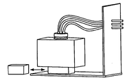
예시적인 실시예에서, 스트레인계 또는 로드셀과 같은 저울이 분배될 재료를 수납하는 저장조 아래에 배치된다. 재료는 잉크 또는 용제일 수도 있고, 저장조는 프린터 내에 수납될 수도 있다. 로드셀은, 로드셀로부터의 전자 신호를 필터링하고 처리하는 프로세서에 접속되어, 분배 중에 중량을 기록하기 위해 분배 응용 제어 로직에 송신되는 중량 측정치로 상기 신호를 변환한다. 분배 장치(예를 들어, 프린터) 내의 저장조 내외로 분배되는 재료를 운반하는 튜브는, 이하에 설명되는 3가지 방법 중 하나에 의해 저장조 내에 삽입되는데, 이 방법들 각각은 접속 튜브에 의해 저장조에 인가된 외력이 변동하는 문제점을 해결한다. 이 방식으로, 기록된 중량은 소프트웨어 애플리케이션 또는 분배 제어 유닛 제어기에 의해 로그되고(logged), 선택적으로 스크린 상에서 조작자에 표시될 수도 있다.In an exemplary embodiment, a balance, such as a strain gauge or load cell, is disposed under the reservoir to contain the material to be dispensed. The material may be ink or solvent, and the storage tank may be housed in the printer. The load cell is connected to a processor that filters and processes the electronic signal from the load cell and converts the signal to a weight measurement sent to the distributed application control logic to record the weight during distribution. The tubes carrying the material dispensed into and out of the reservoir in a dispensing device (e.g., a printer) are inserted into the reservoir by one of three methods described below, each of which is applied Thereby solving the problem that the external force is varied. In this manner, the recorded weight may be logged by the software application or the distribution control unit controller and optionally displayed on the screen to the operator.
도 1 내지 도 20은 커넥터를 둘러싸는 가요성 멤브레인을 도시한 것이다.
도 21 내지 도 26은 커넥터와 분배 유닛 사이의 가요성 튜브 섹션을 도시한 것이다.
도 27 내지 도 29은 슬라이딩 캡을 도시한 것이다.Figures 1 to 20 illustrate a flexible membrane surrounding a connector.
Figures 21-26 illustrate a flexible tube section between the connector and the dispensing unit.
Figures 27 to 29 show the sliding cap.
저장조와 분배 유닛 사이에서 커넥터에 의해 저장조 상에 인가된 힘의 변동으로 인한 문제점을 해결하기 위해, 이하의 3가지 해결책이 설명된다.In order to solve the problem caused by the variation of the force applied on the reservoir by the connector between the reservoir and the dispensing unit, the following three solutions are described.
1. 커넥터를 둘러싸는 가요성 멤브레인(도 1 내지 도 20)1. Flexible membranes surrounding the connector (Figures 1 - 20)
2. 커넥터와 분배 유닛 사이의 가요성 튜브 섹션(도 21 내지 도 26)2. Flexible tube section between the connector and the dispensing unit (Figs. 21-26)
3. 슬라이딩 캡(도 27 내지 도 29)3. Sliding cap (Figs. 27-29)
1. 커넥터를 둘러싸는 가요성 멤브레인(본 항목에서 모든 도면 부호는 도 1 내지 도 20을 참조함) 1. Flexible membrane surrounding the connector (all reference numerals in this section refer to Figs. 1 to 20)
재료 저장조 상의 외력은 저장조의 개방 마우스부(open mouth) 내로 직접 커넥터[튜브, 케이블, 니들(needle) 등]를 배치함으로써 제거될 수도 있지만, 재료가 증발 또는 승화를 겪게 되면 또는 본 명세서에 또한 용기라 칭하는 저장조가 다른 이유로 폐쇄 상태로 유지되어야 하면, 또는 재료가 위험성이 있거나 변질되게 되면, 이러한 해결책은 실행 가능하지 않다. 이 경우에, 저장조의 개구는, 낮은 탄성을 가질 수도 있는 적합한 재료[예를 들어, 테플론 FEP, PFA 및 TFE; 폴리프로필렌(PP), 폴리프로필렌 코폴리머(PPCO)]로 제조된 밀봉부(seal), 멤브레인, 필름 또는 포일로 폐쇄될 수도 있고, 이 개구 내로 튜브들이 압박되어 튜브들이 저장조 내에 삽입되고 재료의 분배 또는 재충전을 허용한다.The external force on the material reservoir may be removed by placing the connector (tube, cable, needle, etc.) directly into the open mouth of the reservoir, but when the material undergoes evaporation or sublimation, This solution is not feasible if the reservoir referred to as " reservoir " should remain closed for other reasons, or if the material becomes hazardous or deteriorated. In this case, the opening of the reservoir may be made of a suitable material (e.g. Teflon FEP, PFA and TFE; A membrane, a film or a foil, the tubes being pressed into the openings, the tubes being inserted into the reservoir and the distribution of the material (s) being < RTI ID = 0.0 & Or recharging.
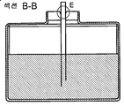
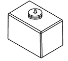
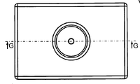
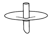
밀봉부를 사용하는 것은 분배 중에 무단 개봉 방지(tamper-evidence)를 제공하고 저장조가 분배 유닛 내에 배치되기 전에 창고 보관 가능하게 하는 부가의 장점을 갖는다. 재료를 제거하거나 저장조 내에 삽입하려는 시도는 밀봉부를 파괴할 가능성이 높을 것이고, 이는 멤브레인 내에 분명한 자취(구멍)를 남기게 될 것이다. 도 1은 밀봉된 개구(3)를 갖고 분배될 재료(2)를 수납하는 저장조(1)를 도시하고 있다.The use of a seal has the added advantage of providing tamper-evidence during dispensing and enabling the storage to be warehoused before being placed in the dispensing unit. Attempts to remove material or insert into the reservoir will likely destroy the seal, leaving a clear trace (hole) in the membrane. Figure 1 shows a
튜브는 도 6에 도시되어 있는 바와 같이 멤브레인 내로 이들 튜브를 가압함으로써 저장조 내에 삽입된다. 단지 하나의 튜브만이 예시의 목적으로 도시되어 있지만, 실제로는 상이한 유형의 재료가 추가되거나 제거되어야 하면 다수의 튜브가 멤브레인을 통해 삽입될 수도 있다. 하나의 튜브는 저장조로부터 재료를 분배하기 위해 사용될 수도 있고, 반면에 다른 튜브는 미사용 재료를 저장조 내로 복귀시키기 위해 사용될 수도 있다. 몇몇 용례에서, 특정 점도를 유지하기 위해 재료에 용제를 추가할 필요가 있을 수도 있고, 이 경우에 부가의 튜브가 요구될 수도 있다. 데이터 또는 전기 신호와 같은 다른 신호를, 센서 및 분배 장치의 제어 유닛으로 그리고 센서 및 분배 장치의 제어 유닛로부터 전달하기 위해 저장조 내에 배치된 센서에 접속된 케이블 또는 도관과 같은 다른 유형의 커넥터가 멤브레인을 통해 저장조 내에 또한 삽입될 수도 있다.The tubes are inserted into the reservoir by pressing these tubes into the membrane as shown in Fig. Although only one tube is shown for illustrative purposes, in practice, multiple tubes may be inserted through the membrane if different types of material have to be added or removed. One tube may be used to dispense the material from the reservoir while the other tube may be used to return the unused material into the reservoir. In some applications, it may be necessary to add a solvent to the material to maintain a certain viscosity, in which case additional tubes may be required. Other types of connectors, such as cables or conduits, connected to the sensors disposed in the reservoir for delivering other signals, such as data or electrical signals, to the control unit of the sensor and the dispensing device and from the control unit of the sensor and the dispensing device, May also be inserted into the reservoir through the opening.
멤브레인(3)은 접착, 또는 열이나 초음파 밀봉과 같은 밀봉 방법에 의해 저장조의 마우스부에 고정된다. 도 3은 개구의 측면들을 가로질러 밀봉부(3)를 갖고 저장조에 부착된 멤브레인(2)의 에지의 확대도를 도시하고 있다. 선택된 밀봉 방법은, 튜브들이 개구의 측면들의 밀봉부를 당겨 제거하지 않으면서 삽입될 수 있도록 멤브레인이 튜브에 의해 천공될 때 인가되는 힘을 견디기에 충분히 강한 밀봉부를 생성할 것이다. 기밀한 밀봉부는 또한, 용기가 상하 전복되어도 밀봉부가 파괴하지 않는 것을 보장한다. 분배되는 재료가 부식성이면, 멤브레인은, 내부의 재료와 접촉하게 됨으로써 약화되거나 손상되는 것을 회피하기 위해 저장조 내에 수납된 재료의 부식 효과에 저항성이 있는 재료로 제조될 수도 있다. 예를 들어, 다수의 산업용 용제는, 밀봉 멤브레인으로서 통상적으로 사용된 몇몇 유형의 재료에 손상을 입히는 것으로 알려져 있다.The
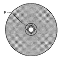
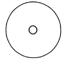
튜브의 단부는 도 9 및 도 10에 도시되어 있는 바와 같이 관통을 위한 특정 형상을 갖도록 설계될 수도 있고 또는 예를 들어 삽입을 보조하기 위해, 날카로운 금속 첨단(metal point) 또는 유사한 형상을 갖는 특정 캡을 구비할 수도 있다. 튜브가 저장조 내에 삽입될 때, 멤브레인은 부분적으로 인열되어 튜브가 용기 내에 재료를 진입시키게 한다. 개구는 도 8에 도시되어 있는 다이아몬드 형상과 같은 특정 패턴을 가질 수도 있는데, 여기서 원형 튜브가 다이아몬드의 측면들의 중심에 접촉하고 있다. 본 예에서, 밀봉부는 완벽하지는 않고, 소량의 공기가 도 11에 도시되어 있는 바와 같이, 코너의 간격을 통해 저장조 내외로 통과할 수도 있다. The end of the tube may be designed to have a specific shape for penetration as shown in Figs. 9 and 10, or may be designed to have a specific metal cap or similar shape with a sharp metal tip or similar shape . When the tube is inserted into the reservoir, the membrane is partially torn to allow the tube to enter the material in the container. The opening may have a specific pattern, such as the diamond shape shown in Figure 8, wherein the circular tube is in contact with the center of the sides of the diamond. In this example, the seal is not perfect, and a small amount of air may pass into and out of the reservoir through the interval of the corners, as shown in Fig.
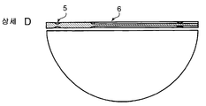
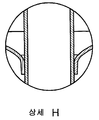
일 실시예에서, 멤브레인의 재료는, 튜브가 삽입되어야 하는 위치를 지시하는 표시부를 포함하도록 설계된다. 표시부 주위의 멤브레인의 영역은, 튜브들이 도 2에 도시되어 있는 바와 같이 멤브레인 내로 가압될 때 전체 멤브레인이 인열되지 않도록 인열의 위치를 제어하기 위해 주위 재료보다 얇을 수도 있다. 일 실시예에서, 표시된 영역은 멤브레인의 제조 중에 예비 성형되는 원형 링에 의해 둘러싸인 십자형부를 포함한다. 준비된 멤브레인의 단면은 도 4에 도시되어 있고, 여기서 십자부의 기다란 바아(bar)가 6으로 지시되어 있다. 링(5)의 더 얇은 섹션은, 튜브가 십자부 내로 가압될 때, 멤브레인이 인열될 수 있으면서도, 원형 링에 도달할 때 인열이 중단되어 멤브레인을 완전히 파괴하는 것을 회피하도록 하기 위해 인열을 제한한다.In one embodiment, the material of the membrane is designed to include a display that indicates where the tube should be inserted. The area of the membrane around the display may be thinner than the surrounding material to control the position of the phosphorus so that the entire membrane is not tearable when the tubes are pressed into the membrane as shown in Fig. In one embodiment, the marked area includes a cruciform surrounded by a circular ring that is preformed during manufacture of the membrane. The cross-section of the prepared membrane is shown in Figure 4, where the elongated bar of the cross is indicated at 6. The thinner section of
튜브는 튜브와 멤브레인 사이의 정지 마찰력(static friction)에 의해 지지된다. 배관 상에 인가된 힘이 튜브와 멤브레인 사이의 정마찰 계수를 극복하는 데 불충분한 한, 멤브레인의 재료는 보상을 위해 약간 변형될 것이고 튜브는 적소에 유지될 것이다. 힘이 재료의 변형에 의해 흡수될 수 있는 것보다 커지게 되고 정마찰 계수보다 커지게 되면, 튜브는 슬립하여(slip), 마찰 계수에 재차 도달될 때까지 튜브 상의 부가의 힘을 완화시킨다. 가변 외력은 따라서 이 스틱-슬립 현상(stick-slip phenomenon)에 의해 실질적으로 제거된다.The tube is supported by static friction between the tube and the membrane. As long as the force applied on the pipe is insufficient to overcome the coefficient of static friction between the tube and the membrane, the material of the membrane will be slightly deformed to compensate and the tube will remain in place. When the force becomes larger than can be absorbed by the deformation of the material and becomes larger than the static coefficient of friction, the tube slips and relaxes the additional force on the tube until it reaches the coefficient of friction again. The variable external force is thus substantially removed by this stick-slip phenomenon.
튜브들이 멤브레인을 통해 저장조 내에 삽입될 때 더 기밀한 밀봉부가 튜브 주위에 요구되면, 멤브레인은 그 초기 형상으로 복귀하려고 시도할 것인 탄성 재료로 제조될 수도 있어, 일단 저장조 내에 가압되면 튜브 주위에 기밀한 밀봉부를 형성한다. 접속 튜브들로부터의 가변력에 응답하는 탄성 멤브레인의 변형은 로드셀에 의해 측정된 중량에 대한 가변력의 영향을 감쇠시킨다.If a more hermetic seal is required around the tube when the tubes are inserted into the reservoir through the membrane, the membrane may be made of an elastic material that will attempt to return to its initial shape, once it is pushed into the reservoir, Thereby forming a sealed portion. The deformation of the elastic membrane in response to the variable force from the connecting tubes dampens the influence of the variable force on the weight measured by the load cell.
이는 도 14 내지 도 19에 도시되어 있다. 튜브는 탄성 멤브레인 내에 가압되고, 이 탄성 멤브레인은 이어서 튜브에 의한 관통 후에 그 초기 형상으로 복귀하려고 시도함에 따라 튜브 주위에 밀봉부를 형성한다(도 19). 튜브 상의 힘이 변함에 따라, 멤브레인은 힘의 변동에 의존하여, 상방으로 또는 하방으로 변형될 것이다(도 17 및 도 18). 저장조 상에 인가된 힘의 수직 성분은, 멤브레인이 변형됨에 따라 수직 성분 및 수평 성분으로 분해될 수 있어, 로드셀 측정에 영향을 미치는 저장조 상의 수직력이 레버 아암의 길이, 즉 멤브레인의 반경에 비례하는 팩터(factor)만큼 감쇠되게 될 것이다. 멤브레인이 그 최소량 및 최대량만큼 변위될 때 진입된 튜브(plunged tube)에 대해 멤브레인에 의해 인가된 힘의 수직 성분의 최종적인 차이는, 원하는 측정 정확도에 등가인 재료의 양이 추가되거나 제거될 때 중량 센서에 인가된 힘보다 열등하다.This is shown in Figs. 14-19. The tube is pressed into the resilient membrane, which then seals around the tube as it attempts to return to its initial shape after penetration by the tube (Fig. 19). As the force on the tube changes, the membrane will deform upwardly or downwardly, depending on the force variation (Figs. 17 and 18). The vertical component of the force applied on the reservoir can be decomposed into vertical and horizontal components as the membrane deforms so that the vertical force on the reservoir that affects the load cell measurement is proportional to the length of the lever arm, which will be attenuated by a factor of. The final difference in the vertical component of the force applied by the membrane relative to the plunged tube when the membrane is displaced by its minimum amount and maximum amount is determined by the weight of the material when the amount of material equivalent to the desired measurement accuracy is added or removed It is inferior to the force applied to the sensor.
멤브레인의 특성에 관한 이전의 관찰은, 멤브레인을 관통할 때 인가된 힘뿐만 아니라 저장조가 상하 전복될 때의 내부 재료의 중량을 지지할 수 있는 열 또는 초음파 밀봉과 같은 밀봉 방법 또는 접착에 의해 저장조의 마우스부에 재료가 고정되는 것을 적용하였다. 분배되고 있는 재료가 부식성이면, 멤브레인의 재료는, 내용물과 접촉하게 됨으로써 약화되거나 손상되는 것을 회피하기 위해 저장조 내에 수납된 재료의 유형에 의한 손상에 저항성을 갖도록 선택된다. 그러나, 이 경우에, 탄성 멤브레인은 튜브가 저장조 내에 삽입될 때 인열될 것이며, 멤브레인은 접속 튜브로부터 압력의 변동 하에서 파괴 없이 거의 완전히 변형될 것이다.Previous observations of the characteristics of the membrane have been made by the use of a seal or a seal such as a heat or ultrasonic seal capable of supporting the force applied when the membrane is passed through as well as the weight of the internal material when the reservoir is rolled up and down The material was fixed to the mouse part. If the material being dispensed is corrosive, the material of the membrane is selected to be resistant to damage by the type of material contained in the reservoir to avoid being weakened or damaged by coming into contact with the contents. However, in this case, the resilient membrane will be torn when the tube is inserted into the reservoir, and the membrane will almost completely deform without breaking under pressure fluctuations from the connection tube.
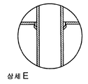
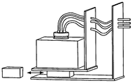
2. 커넥터와 분배 유닛 사이의 가요성 튜브 섹션(본 항목에서 모든 도면 부호는 도 21 내지 도 26을 참조함). 2. Flexible tube section between the connector and the dispensing unit (all reference numerals in this section refer to Figures 21 to 26).
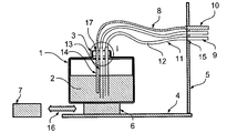
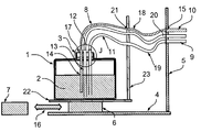
도 21 및 도 24에 도시되어 있는 바와 같이, 중량 센서(6), 예를 들어 로드셀이 저장조(1), 저장조의 내용물(2), 저장조 캡(3), 튜브 홀더(17), 진입된 튜브(13), 진입된 센서(14), 가요성 튜브(13), 튜브 내용물(12), 센서 와이어(8) 및 분배 유닛 조립체에 관련된 다른 부분의 중량을 측정하는 데 사용된다. 중량 센서는 데이터 링크(16)를 사용하여 제어기(7)에 접속된다. 저장조(1)로부터 분배되고 있는 재료(2)는 잉크, 용제 또는 양자의 혼합물을 포함하는 임의의 유형 또는 상태(기체, 액체 또는 고체)일 수 있다.As shown in Figs. 21 and 24, a
모든 재료가 분배되었을 때, 비어 있는 저장조는 교체되거나 재충전될 수도 있다. 교체 또는 재충전 작업은 통상적으로, 저장조 캡(3)을 제거하고 저장조(1)를 다른 용기로 교체하는 것을 요구한다. 저장조(1), 저장조 캡(3), 진입된 튜브(13), 진입된 센서(14) 또는 센서(6) 상에 중량 부과하는 임의의 부분에 대한 제거, 교환, 재충전, 검사 또는 다른 조작 중에, 튜브(11) 및 케이블(8)에 의해 저장조에 인가되는 힘을 변할 수도 있다. 이 변동은 조작 전후에 정확하게 동일한 위치에 있지 않은 튜브(11)와 케이블(8)의 이동에 부분적으로 기인한다. 게다가, 튜브(11) 및/또는 케이블(8)은, 저장조로부터 분배되고 있는 재료의 유동을 차단할 수 있는 꼬임을 방지하면서, 파괴 없이 유지 보수 중에 조작을 허용하는 가요성 또는 부분적 가요성의 재료로 제조된다. 이들 특성에 기인하여, 튜브(11) 및 케이블(8)은, 캡(3) 및 이에 따른 중량 센서(6)에 원하지 않는 가변력을 인가하는데, 이는 저장조로부터 분배되고 있는 재료(2)의 양이 불변으로 유지되는 사실에도 불구하고 중량의 변동을 레지스터(register)할 수도 있다. 중량 센서(6)의 극단부의 이동은 통상적으로 최대 부하에서 수 mm 미만이다.When all the material has been dispensed, the empty reservoir may be replaced or recharged. Replacement or recharging operations typically require removal of the
설명된 문제점을 극복하기 위해, 튜브(11) 및 케이블(8)은 굴곡될 때 매우 w작은 힘을 발생시키는 고도로 가요성인 재료로 제조될 수도 있다. 센서 극단부(6)의 작은 이동에 기인하여, 튜브 및/또는 케이블 위치에 의존하여 캡(3)에 인가되는 원치 않는 힘의 양이 감소된다.In order to overcome the problems described, the
본 실시예에서(도 21 내지 도 23 참조), 가요성 튜브(11) 및 케이블(8)의 제1 극단부는 예를 들어 표준 배관 또는 케이블 고정구를 사용하여, 진입된 튜브(13)와 센서(14)에 접속된다. 가요성 튜브(11) 및 케이블(8)의 제2 극단부는, 이들에 한정되는 것은 아니지만, 튜브를 함께 크림프(crimp)하는 구멍 또는 규격품 표준 배관 또는 케이블 커플링 시스템과 같은 튜브 또는 케이블 고정구 기구(15)를 사용하여 배관 홀더(5)에 모두 속박되는 강성 튜브(9) 및 케이블(10)에 접속된다. 강성 튜브(9) 및 케이블(10)의 제2 극단부는 일반적으로 분배 유닛, 예를 들어 프린터 또는 프린터 헤드(도면에는 도시되어 있지 않음)와 접속된다. 고정구(15)는 튜브(9) 또는 케이블(10)에 의해 인가된 힘을 시스템 본체(4)에 접속되어 있는 튜브 홀더(5)에 전달한다. 튜브(11) 및 케이블(8)의 길이, 배향 및 위치는 저장조(1), 저장조 캡(3), 진입된 튜브(13) 또는 센서(14)의 제거, 교환, 재충전, 검사 또는 다른 조작 중에 대략 동일하게 유지되고, 튜브(11) 및 케이블(8) 재료의 가요성은 임의의 조작 전후에 최종적인 힘의 변동을 감소시킨다.21 to 23), the first extremity of the
다른 실시예에서(도 24 내지 도 26 참조), 가요성 튜브(11) 및 케이블(8)의 제1 극단부는 예를 들어 표준 튜브 또는 케이블 고정구를 사용하여, 진입된 튜브(13)와 센서(14)에 접속된다. 가요성 튜브(11) 및 케이블(8)의 제2 극단부는, 이들에 한정되는 것은 아니지만, 튜브를 함께 크림프하는 구멍 또는 규격품 표준 배관 또는 케이블 커플링 시스템과 같은 튜브 또는 케이블 고정구 기구(21)를 사용하여 용기 홀더(22, 23)에 모두 속박되는 가요성 튜브(19) 및 가요성 케이블(18)에 접속된다. 가요성 튜브(19) 및 가요성 케이블(18)의 다른 극단부는, 이들에 한정되는 것은 아니지만, 튜브를 함께 크림프하는 구멍 또는 규격품 표준 배관 또는 케이블 커플링 시스템과 같은 튜브 또는 케이블 고정구 기구(15)를 사용하여 튜브 홀더(5)에 모두 속박되는 강성 튜브(9) 및 케이블(10)에 접속된다.24-26), the first extremity of the
고정구(15)는 튜브(9) 또는 케이블(10)에 의해 인가된 힘을 시스템 본체(4)에 접속된 튜브 홀더(5)에 전달한다. 튜브(19) 및 케이블(18)의 길이, 배향 및 위치는, 저장조(1), 저장조 캡(3), 진입된 튜브(13) 또는 센서(14)의 제거, 교환, 재충전, 검사 또는 다른 조작 중에 동일하게 유지되고, 튜브(19) 및 케이블(18) 재료의 가요성은 시스템 본체(4)에 대한 저장조 홀더(22, 23)의 작은 이동에 기인하여 최종적인 힘의 변동을 감소시킨다.The
케이블(8), 튜브(11) 및 내부에 수납된 재료(12)에 의해 캡(3)에 인가된 힘은, 관련 힘 루프가 중량 센서(6)를 통과하지 않고 저장조 홀더(22, 23) 내에 수납되기 때문에, 중량 센서(6)에 의해 행해진 측정에 간섭하지 않는다. 따라서, 단지 중량 센서(6)에 의해 측정된 부분에 인가된 외력만이 가요성 튜브(19) 및 케이블(18)에 의해 인가된 힘에 더하여 분배되고 있는 재료의 중량이 된다. 이들 튜브 및 센서는 전혀 조작되지 않고 단지 약간만 이동하기 때문에, 이들에 의해 인가된 힘은 재현 가능하고, 저장조(1), 저장조 캡(3), 진입된 튜브(13) 또는 센서(14)로의 조작이 수행될 때 변하지 않는다.The force applied to the
3. 슬라이딩 캡(본 항목에서의 모든 도면 부호는 도 27 내지 도 29를 참조함) 3. Sliding caps (all reference numerals in this section refer to Figures 27 to 29)
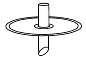
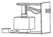
다른 실시예에서, 저장조(1), 저장조 내에 수납된 재료(2), 저장조 캡(3), 및 원통형 평활한 건식 베어링(20)의 중량을 측정하는 데 중량 센서(6)가 사용된다.In another embodiment, the
다른 실시예에서, 진입된 튜브(13) 및 진입된 센서(14)는 튜브 홀더(17)에 의해 단단히 유지된다. 튜브 홀더(17)는 또한 튜브 홀더(5)에 단단히 부착된다. 튜브(11) 및 케이블(8)의 제1 극단부는 예를 들어 표준 튜브 또는 케이블 고정구를 사용하여, 진입된 튜브(13) 및 센서(14)에 접속된다. 튜브(11) 및 케이블(8)의 제2 극단부는, 이들에 한정되는 것은 아니지만, 튜브를 함께 크림프하는 구멍 또는 규격품 표준 배관 또는 케이블 커플링 시스템과 같은 튜브 또는 케이블 고정구 기구(15)를 사용하여 튜브 홀더(5)에 모두 속박되는 강성 튜브(9) 및 케이블(10)에 접속된다. 고정구(15)는 튜브(9) 또는 케이블(10)에 의해 인가된 힘을 시스템 본체(4)에 접속된 튜브 홀더(5)에 전달한다. 중량 센서(6)는 데이터 링크(16)를 사용하여 제어기(7)에 접속된다. 저장조(1)로부터 분배되고 있는 재료(2)는 잉크, 용제 또는 양자의 혼합물을 포함하는 임의의 유형 또는 상태일 수 있다.In another embodiment, the intruded
튜브 홀더(17)는 캡(3)에 단단히 부착된 원통형의 평활한 건식 베어링(20)에 부착되지 않는다. 원통형의 평활한 건식 베어링(20)은 튜브 홀더(17)를 따라 수직으로 그리고 그 주위에서 회전하여 자유롭게 슬라이딩한다.The
중량 센서(6) 상에 배치되거나 그로부터 제거된 중량은 중량의 크기에 비례하는 수직 변형을 야기한다. 이에 따라, 진입된 튜브(13)를 통한 저장조(1)의 비움(또는 충전) 중에, 저장조(1)의 수직 위치가 변한다. 저장조(1)의 수직 위치가 변할 때, [저장조 캡(3) 내의] 원통형의 평활한 건식 베어링(20)은 튜브 홀더(17)를 따라(그리고 주위에서) 자유롭게 (수직으로 그리고 회전하여) 슬라이딩한다.The weight placed on or removed from the
이 방식으로, 저장조(1) 및 저장조 캡(3) 또는 센서(6) 상에 중량 부과하는 임의의 부분의 제거, 교환, 재충전, 검사 또는 다른 조작 중에, 진입된 튜브(13), 진입된 센서(14), 튜브(11) 및 케이블(8)은 모두, 자체로 시스템 본체(4)에 단단히 접속된 튜브 홀더(5)에 자체로 견고하게 부착된 튜브 홀더(17)에 단단히 견고하게 부착되기 때문에, 진입된 튜브(13), 진입된 센서(14), 튜브(11) 및 케이블(8)에 의해 어떠한 힘도 인가되지 않는다.In this way, during the removal, replacement, recharging, inspection or other operation of any part weighing on the
1 : 저장조
3 : 저장조 캡
4 : 시스템 본체
5 : 튜브 홀더
6 : 센서
8 : 케이블
11 : 튜브1: Storage tank
3: Storage tank cap
4: System body
5: Tube holder
6: Sensor
8: Cable
11: Tubes
Claims (20)
상기 분배 장치는 재료의 적어도 일부를 분배하기 위한 분배 유닛을 갖고,
상기 분배 장치는 분배될 재료를 수납하는 저장조를 갖고,
상기 분배 장치는 상기 저장조와 상기 분배 유닛 사이에 커넥터를 더 갖고,
상기 방법은,
상기 저장조 아래에 저울을 배치하는 단계로서, 상기 저울은 상기 저울로부터의 전자 신호를 처리하기 위한 그리고 이 전자 신호를 중량 측정치로 변환하기 위한 프로세서에 접속되는 것인 저울 배치 단계; 및
상기 저장조 내에 튜브를 삽입하는 단계로서, 상기 튜브는 상기 저장조 내로 그리고 상기 저장조로부터 재료를 운반하는 것이고, 상기 저장조 내에 튜브를 삽입하는 단계는,
i. 상기 커넥터를 둘러싸는 가요성 멤브레인을 통하는 것,
ii. 상기 커넥터와 상기 분배 유닛 사이의 가요성 튜브 섹션에 의한 것, 그리고
iii. 상기 저장조에 대해 슬라이딩하는 저장조 캡을 통하는 것
중 하나에 의해 이루어지는 것인 튜브 삽입 단계
를 포함하는, 분배 장치의 제조 방법.A method of manufacturing a dispensing apparatus for measuring an amount of material to be dispensed,
The dispensing device having a dispensing unit for dispensing at least a portion of the material,
The dispensing device has a reservoir for containing the material to be dispensed,
Wherein the distribution device further comprises a connector between the reservoir and the distribution unit,
The method comprises:
Placing a balance under the reservoir, the balance being connected to a processor for processing the electronic signal from the balance and for converting the electronic signal to a weight measurement; And
Inserting a tube into the reservoir, the tube carrying material from and into the reservoir, and inserting the tube into the reservoir,
i. Through a flexible membrane surrounding the connector,
ii. By a flexible tube section between the connector and the dispensing unit, and
iii. Through a reservoir cap sliding against the reservoir
The tube insertion step < RTI ID = 0.0 >
Wherein the dispensing apparatus comprises:
재료의 적어도 일부를 분배하기 위한 분배 유닛;
분배될 재료를 수납하는 저장조;
상기 저장조와 상기 분배 유닛 사이의 커넥터;
상기 저장조 아래의 저울로서, 상기 저울은 상기 저울로부터의 전자 신호를 처리하기 위한 그리고 이 전자 신호를 중량 측정치로 변환하기 위한 프로세서에 접속되는 것인, 저울; 및
상기 저장조 내에 삽입된 튜브로서, 상기 튜브는 상기 저장조 내로 그리고 상기 저장조로부터 재료를 운반하고, 상기 튜브는,
i. 상기 커넥터를 둘러싸는 가요성 멤브레인을 통하는 것,
ii. 상기 커넥터와 상기 분배 유닛 사이의 가요성 튜브 섹션에 의한 것, 그리고
iii. 상기 저장조에 대해 슬라이딩하는 저장조 캡을 통하는 것
중 하나에 의해 상기 저장조 내에 삽입되는 것인 튜브
를 포함하는 분배 장치.A dispensing device for measuring an amount of material to be dispensed,
A dispensing unit for dispensing at least a portion of the material;
A reservoir for containing the material to be dispensed;
A connector between the reservoir and the dispensing unit;
A balance under said reservoir, said balance being connected to a processor for processing an electronic signal from said balance and for converting said electronic signal to a weight measurement; And
A tube inserted into the reservoir, the tube carrying material into and from the reservoir,
i. Through a flexible membrane surrounding the connector,
ii. By a flexible tube section between the connector and the dispensing unit, and
iii. Through a reservoir cap sliding against the reservoir
Said tube being inserted into said reservoir by one of said tubes
≪ / RTI >
Applications Claiming Priority (3)
| Application Number | Priority Date | Filing Date | Title |
|---|---|---|---|
| US201261720080P | 2012-10-30 | 2012-10-30 | |
| US61/720,080 | 2012-10-30 | ||
| PCT/EP2013/060302 WO2014067672A1 (en) | 2012-10-30 | 2013-05-17 | System and method for monitoring weight of material in reservoir |
Publications (1)
| Publication Number | Publication Date |
|---|---|
| KR20150080513A true KR20150080513A (en) | 2015-07-09 |
Family
ID=48576358
Family Applications (1)
| Application Number | Title | Priority Date | Filing Date |
|---|---|---|---|
| KR1020157012724A KR20150080513A (en) | 2012-10-30 | 2013-05-17 | System and method for monitoring weight of material in reservoir |
Country Status (23)
| Country | Link |
|---|---|
| US (1) | US10078004B2 (en) |
| EP (1) | EP2914939B1 (en) |
| JP (1) | JP2016500820A (en) |
| KR (1) | KR20150080513A (en) |
| CN (1) | CN104755889A (en) |
| AR (1) | AR093265A1 (en) |
| AU (1) | AU2013339799A1 (en) |
| BR (1) | BR112013013368B1 (en) |
| CA (1) | CA2884871A1 (en) |
| CL (1) | CL2015001012A1 (en) |
| CO (1) | CO7350639A2 (en) |
| EA (1) | EA201590858A1 (en) |
| EC (1) | ECSP15016846A (en) |
| HK (1) | HK1210633A1 (en) |
| HU (1) | HUE061446T2 (en) |
| IL (1) | IL238054A0 (en) |
| IN (1) | IN2015DN02131A (en) |
| MX (1) | MX2015005398A (en) |
| SG (1) | SG11201502001QA (en) |
| TN (1) | TN2015000103A1 (en) |
| TW (1) | TW201423056A (en) |
| WO (1) | WO2014067672A1 (en) |
| ZA (1) | ZA201502109B (en) |
Cited By (1)
| Publication number | Priority date | Publication date | Assignee | Title |
|---|---|---|---|---|
| KR101888951B1 (en) * | 2017-05-23 | 2018-08-16 | 세일정기 (주) | Appratus for measuring weight of electrodeposited metal and methodfor using the same |
Families Citing this family (6)
| Publication number | Priority date | Publication date | Assignee | Title |
|---|---|---|---|---|
| JP6288027B2 (en) * | 2015-09-28 | 2018-03-07 | 株式会社タツノ | Calibration apparatus and calibration method |
| WO2018019930A1 (en) * | 2016-07-27 | 2018-02-01 | Bühler AG | Electromechanical actuating drive for a bulk-goods shut-off element |
| WO2020027831A1 (en) | 2018-08-01 | 2020-02-06 | Hewlett-Packard Development Company, L.P. | Load cells for print supplies |
| CN109188013A (en) * | 2018-08-27 | 2019-01-11 | 北京交通大学 | A kind of water sand mixture solid phase flow velocity real-time measurement device and method |
| CN110864786A (en) * | 2019-11-11 | 2020-03-06 | 重庆首厚智能科技研究院有限公司 | Article management method with tray |
| WO2023107826A1 (en) * | 2021-12-10 | 2023-06-15 | Kateeva, Inc. | Print material reservoir, printhead assembly and inkjet printer |
Family Cites Families (19)
| Publication number | Priority date | Publication date | Assignee | Title |
|---|---|---|---|---|
| DE4002255A1 (en) * | 1990-01-26 | 1991-08-01 | Fluid Verfahrenstechnik Gmbh | Liquid dosing arrangement for very small and large quantities - has buffer container between reservoir and valve for developer small quantities |
| US5731824A (en) * | 1995-12-18 | 1998-03-24 | Xerox Corporation | Ink level sensing system for an ink jet printer |
| SE508434C2 (en) * | 1996-02-23 | 1998-10-05 | Scanrex Automation Ab | Method and system of dosing |
| JP2000103080A (en) | 1998-07-31 | 2000-04-11 | Oki Data Corp | Liquid storage container and method for filling it with liquid |
| AU2001289472A1 (en) * | 2000-10-06 | 2002-04-15 | Chemspeed Ltd | Device comprising a tool holder and a removably attachable tool |
| JP4608110B2 (en) | 2001-01-22 | 2011-01-05 | 株式会社イシダ | Combination weighing device |
| US6742882B2 (en) | 2001-06-26 | 2004-06-01 | Brother Kogyo Kabushiki Kaisha | Air purge device for ink jet recording apparatus |
| JP3901718B2 (en) | 2001-06-26 | 2007-04-04 | ブラザー工業株式会社 | Inkjet recording device |
| JP4448643B2 (en) | 2002-05-07 | 2010-04-14 | セイコーエプソン株式会社 | Inkjet recording device |
| US7725209B2 (en) * | 2002-11-12 | 2010-05-25 | Objet Geometries Ltd | Three-dimensional object printing |
| US7575409B2 (en) | 2005-07-01 | 2009-08-18 | Allison Advanced Development Company | Apparatus and method for active control of blade tip clearance |
| US7770448B2 (en) | 2005-09-16 | 2010-08-10 | Air Liquide Electronics U.S. LP. | Chemical storage device with integrated load cell |
| JP2007223220A (en) | 2006-02-24 | 2007-09-06 | Brother Ind Ltd | Ink-jet printer |
| JP2010164722A (en) | 2009-01-15 | 2010-07-29 | Seiko Epson Corp | Tank device and droplet delivery device |
| EP2218514B1 (en) * | 2009-02-09 | 2017-04-26 | J. Wagner AG | Coating powder supply device |
| US9102509B2 (en) * | 2009-09-25 | 2015-08-11 | Ecolab Inc. | Make-up dispense in a mass based dispensing system |
| JP5682807B2 (en) | 2010-07-14 | 2015-03-11 | 株式会社リコー | Ink supply apparatus and image forming apparatus |
| US8534497B2 (en) * | 2010-09-20 | 2013-09-17 | Prince Castle, LLC | Dispensing method and apparatus utilizing a sensor to determine a time that a dispensing valve is open |
| US8813793B2 (en) * | 2011-08-02 | 2014-08-26 | Dedoes Industries, Inc. | Paint formulation and dispensing apparatus |
-
2013
- 2013-05-17 CN CN201380056678.5A patent/CN104755889A/en active Pending
- 2013-05-17 WO PCT/EP2013/060302 patent/WO2014067672A1/en active Application Filing
- 2013-05-17 CA CA2884871A patent/CA2884871A1/en not_active Abandoned
- 2013-05-17 JP JP2015538333A patent/JP2016500820A/en active Pending
- 2013-05-17 AU AU2013339799A patent/AU2013339799A1/en not_active Abandoned
- 2013-05-17 US US14/439,397 patent/US10078004B2/en active Active
- 2013-05-17 SG SG11201502001QA patent/SG11201502001QA/en unknown
- 2013-05-17 KR KR1020157012724A patent/KR20150080513A/en not_active Application Discontinuation
- 2013-05-17 BR BR112013013368-6A patent/BR112013013368B1/en active IP Right Grant
- 2013-05-17 HU HUE13726701A patent/HUE061446T2/en unknown
- 2013-05-17 MX MX2015005398A patent/MX2015005398A/en unknown
- 2013-05-17 IN IN2131DEN2015 patent/IN2015DN02131A/en unknown
- 2013-05-17 EP EP13726701.9A patent/EP2914939B1/en active Active
- 2013-05-17 EA EA201590858A patent/EA201590858A1/en unknown
- 2013-10-25 TW TW102138580A patent/TW201423056A/en unknown
- 2013-10-29 AR ARP130103945A patent/AR093265A1/en unknown
-
2015
- 2015-03-18 TN TNP2015000103A patent/TN2015000103A1/en unknown
- 2015-03-26 ZA ZA2015/02109A patent/ZA201502109B/en unknown
- 2015-03-31 IL IL238054A patent/IL238054A0/en unknown
- 2015-04-21 CL CL2015001012A patent/CL2015001012A1/en unknown
- 2015-04-29 EC ECIEPI201516846A patent/ECSP15016846A/en unknown
- 2015-04-30 CO CO15099184A patent/CO7350639A2/en unknown
- 2015-11-18 HK HK15111369.3A patent/HK1210633A1/en unknown
Cited By (1)
| Publication number | Priority date | Publication date | Assignee | Title |
|---|---|---|---|---|
| KR101888951B1 (en) * | 2017-05-23 | 2018-08-16 | 세일정기 (주) | Appratus for measuring weight of electrodeposited metal and methodfor using the same |
Also Published As
| Publication number | Publication date |
|---|---|
| CL2015001012A1 (en) | 2015-07-24 |
| AU2013339799A1 (en) | 2015-04-02 |
| CO7350639A2 (en) | 2015-08-10 |
| ECSP15016846A (en) | 2015-12-31 |
| CA2884871A1 (en) | 2014-05-08 |
| BR112013013368A2 (en) | 2016-09-13 |
| IL238054A0 (en) | 2015-05-31 |
| TN2015000103A1 (en) | 2016-06-29 |
| EP2914939A1 (en) | 2015-09-09 |
| TW201423056A (en) | 2014-06-16 |
| US20150247753A1 (en) | 2015-09-03 |
| HK1210633A1 (en) | 2016-04-29 |
| AR093265A1 (en) | 2015-05-27 |
| MX2015005398A (en) | 2015-07-21 |
| EA201590858A1 (en) | 2015-10-30 |
| BR112013013368B1 (en) | 2021-02-02 |
| EP2914939B1 (en) | 2023-03-01 |
| US10078004B2 (en) | 2018-09-18 |
| CN104755889A (en) | 2015-07-01 |
| HUE061446T2 (en) | 2023-07-28 |
| JP2016500820A (en) | 2016-01-14 |
| WO2014067672A1 (en) | 2014-05-08 |
| IN2015DN02131A (en) | 2015-08-14 |
| ZA201502109B (en) | 2016-10-26 |
| SG11201502001QA (en) | 2015-05-28 |
Similar Documents
| Publication | Publication Date | Title |
|---|---|---|
| KR20150080513A (en) | System and method for monitoring weight of material in reservoir | |
| US6494343B2 (en) | Fluid storage and dispensing system featuring ex-situ strain gauge pressure monitoring assembly | |
| JP2878581B2 (en) | Monitor device | |
| US10994984B2 (en) | Level sensing apparatus | |
| US20040055391A1 (en) | Method and apparatus for remotely monitoring corrosion using corrosion coupons | |
| US20110138892A1 (en) | Methods and Systems for Determining Process Variables Using Location of Center of Gravity | |
| AU2018267576A1 (en) | Pressurized fluid container with strain gauge and remote communication means | |
| EP3118583A1 (en) | Modular sealing apparatus with failure detection unit | |
| JP5218866B2 (en) | Dissolvability measurement system using piezoelectric sensor | |
| US11761838B2 (en) | Sensing using nanoparticle based strain sensors | |
| CN102667304B (en) | Gas cylinder with measuring connection | |
| JP6282301B2 (en) | Hydrogen remaining amount sensor | |
| US11326968B2 (en) | Devices and methods for detecting axial forces applied to a container | |
| JP4206498B2 (en) | Liquid storage tank leak detection system | |
| EP3299775A1 (en) | Calibration device | |
| CN110044789B (en) | Device and method for measuring minimum starting pressure and pressure wave propagation rate | |
| US20080245155A1 (en) | Method and apparatus to digitize pressure gauge information | |
| US6250153B1 (en) | Continuous, non-metallic, media sensors for corrosive environments | |
| US20100212402A1 (en) | Method and apparatus for precision non-destructive non-contact control of super small differences of pressure | |
| CN207908090U (en) | A kind of liquid motion direction thrust measurement device | |
| CN219302394U (en) | Air marking management system | |
| EP2889597B1 (en) | Aircraft fuel tank comprising a system for remotely measuring pressure | |
| EP4022212B1 (en) | Valve with integrated sensor |
Legal Events
| Date | Code | Title | Description |
|---|---|---|---|
| WITN | Application deemed withdrawn, e.g. because no request for examination was filed or no examination fee was paid |