KR20150067760A - Transformerless on-site generation - Google Patents
Transformerless on-site generation Download PDFInfo
- Publication number
- KR20150067760A KR20150067760A KR1020157011760A KR20157011760A KR20150067760A KR 20150067760 A KR20150067760 A KR 20150067760A KR 1020157011760 A KR1020157011760 A KR 1020157011760A KR 20157011760 A KR20157011760 A KR 20157011760A KR 20150067760 A KR20150067760 A KR 20150067760A
- Authority
- KR
- South Korea
- Prior art keywords
- voltage
- line voltage
- rectified line
- electrolytic cells
- varying
- Prior art date
Links
Images


Classifications
-
- C—CHEMISTRY; METALLURGY
- C25—ELECTROLYTIC OR ELECTROPHORETIC PROCESSES; APPARATUS THEREFOR
- C25B—ELECTROLYTIC OR ELECTROPHORETIC PROCESSES FOR THE PRODUCTION OF COMPOUNDS OR NON-METALS; APPARATUS THEREFOR
- C25B9/00—Cells or assemblies of cells; Constructional parts of cells; Assemblies of constructional parts, e.g. electrode-diaphragm assemblies; Process-related cell features
- C25B9/60—Constructional parts of cells
- C25B9/65—Means for supplying current; Electrode connections; Electric inter-cell connections
-
- H—ELECTRICITY
- H02—GENERATION; CONVERSION OR DISTRIBUTION OF ELECTRIC POWER
- H02M—APPARATUS FOR CONVERSION BETWEEN AC AND AC, BETWEEN AC AND DC, OR BETWEEN DC AND DC, AND FOR USE WITH MAINS OR SIMILAR POWER SUPPLY SYSTEMS; CONVERSION OF DC OR AC INPUT POWER INTO SURGE OUTPUT POWER; CONTROL OR REGULATION THEREOF
- H02M3/00—Conversion of dc power input into dc power output
- H02M3/02—Conversion of dc power input into dc power output without intermediate conversion into ac
- H02M3/04—Conversion of dc power input into dc power output without intermediate conversion into ac by static converters
- H02M3/10—Conversion of dc power input into dc power output without intermediate conversion into ac by static converters using discharge tubes with control electrode or semiconductor devices with control electrode
- H02M3/145—Conversion of dc power input into dc power output without intermediate conversion into ac by static converters using discharge tubes with control electrode or semiconductor devices with control electrode using devices of a triode or transistor type requiring continuous application of a control signal
- H02M3/155—Conversion of dc power input into dc power output without intermediate conversion into ac by static converters using discharge tubes with control electrode or semiconductor devices with control electrode using devices of a triode or transistor type requiring continuous application of a control signal using semiconductor devices only
-
- C—CHEMISTRY; METALLURGY
- C25—ELECTROLYTIC OR ELECTROPHORETIC PROCESSES; APPARATUS THEREFOR
- C25B—ELECTROLYTIC OR ELECTROPHORETIC PROCESSES FOR THE PRODUCTION OF COMPOUNDS OR NON-METALS; APPARATUS THEREFOR
- C25B11/00—Electrodes; Manufacture thereof not otherwise provided for
- C25B11/02—Electrodes; Manufacture thereof not otherwise provided for characterised by shape or form
- C25B11/036—Bipolar electrodes
-
- C—CHEMISTRY; METALLURGY
- C25—ELECTROLYTIC OR ELECTROPHORETIC PROCESSES; APPARATUS THEREFOR
- C25B—ELECTROLYTIC OR ELECTROPHORETIC PROCESSES FOR THE PRODUCTION OF COMPOUNDS OR NON-METALS; APPARATUS THEREFOR
- C25B15/00—Operating or servicing cells
-
- C—CHEMISTRY; METALLURGY
- C25—ELECTROLYTIC OR ELECTROPHORETIC PROCESSES; APPARATUS THEREFOR
- C25B—ELECTROLYTIC OR ELECTROPHORETIC PROCESSES FOR THE PRODUCTION OF COMPOUNDS OR NON-METALS; APPARATUS THEREFOR
- C25B15/00—Operating or servicing cells
- C25B15/02—Process control or regulation
-
- C—CHEMISTRY; METALLURGY
- C25—ELECTROLYTIC OR ELECTROPHORETIC PROCESSES; APPARATUS THEREFOR
- C25B—ELECTROLYTIC OR ELECTROPHORETIC PROCESSES FOR THE PRODUCTION OF COMPOUNDS OR NON-METALS; APPARATUS THEREFOR
- C25B15/00—Operating or servicing cells
- C25B15/02—Process control or regulation
- C25B15/023—Measuring, analysing or testing during electrolytic production
- C25B15/025—Measuring, analysing or testing during electrolytic production of electrolyte parameters
- C25B15/033—Conductivity
-
- C25B9/04—
-
- C25B9/063—
-
- C—CHEMISTRY; METALLURGY
- C25—ELECTROLYTIC OR ELECTROPHORETIC PROCESSES; APPARATUS THEREFOR
- C25B—ELECTROLYTIC OR ELECTROPHORETIC PROCESSES FOR THE PRODUCTION OF COMPOUNDS OR NON-METALS; APPARATUS THEREFOR
- C25B9/00—Cells or assemblies of cells; Constructional parts of cells; Assemblies of constructional parts, e.g. electrode-diaphragm assemblies; Process-related cell features
- C25B9/70—Assemblies comprising two or more cells
- C25B9/73—Assemblies comprising two or more cells of the filter-press type
- C25B9/75—Assemblies comprising two or more cells of the filter-press type having bipolar electrodes
-
- H—ELECTRICITY
- H02—GENERATION; CONVERSION OR DISTRIBUTION OF ELECTRIC POWER
- H02M—APPARATUS FOR CONVERSION BETWEEN AC AND AC, BETWEEN AC AND DC, OR BETWEEN DC AND DC, AND FOR USE WITH MAINS OR SIMILAR POWER SUPPLY SYSTEMS; CONVERSION OF DC OR AC INPUT POWER INTO SURGE OUTPUT POWER; CONTROL OR REGULATION THEREOF
- H02M1/00—Details of apparatus for conversion
- H02M1/0067—Converter structures employing plural converter units, other than for parallel operation of the units on a single load
- H02M1/007—Plural converter units in cascade
-
- H—ELECTRICITY
- H02—GENERATION; CONVERSION OR DISTRIBUTION OF ELECTRIC POWER
- H02M—APPARATUS FOR CONVERSION BETWEEN AC AND AC, BETWEEN AC AND DC, OR BETWEEN DC AND DC, AND FOR USE WITH MAINS OR SIMILAR POWER SUPPLY SYSTEMS; CONVERSION OF DC OR AC INPUT POWER INTO SURGE OUTPUT POWER; CONTROL OR REGULATION THEREOF
- H02M7/00—Conversion of ac power input into dc power output; Conversion of dc power input into ac power output
- H02M7/02—Conversion of ac power input into dc power output without possibility of reversal
- H02M7/04—Conversion of ac power input into dc power output without possibility of reversal by static converters
- H02M7/12—Conversion of ac power input into dc power output without possibility of reversal by static converters using discharge tubes with control electrode or semiconductor devices with control electrode
- H02M7/21—Conversion of ac power input into dc power output without possibility of reversal by static converters using discharge tubes with control electrode or semiconductor devices with control electrode using devices of a triode or transistor type requiring continuous application of a control signal
- H02M7/217—Conversion of ac power input into dc power output without possibility of reversal by static converters using discharge tubes with control electrode or semiconductor devices with control electrode using devices of a triode or transistor type requiring continuous application of a control signal using semiconductor devices only
-
- H02M2001/007—
Abstract
동작하기 위해 변압기의 사용을 요구하지 않는 전기 분해용 방법들 및 장치들. 장치는 셀 또는 셀들로 하여금 전압 조정(voltage regulation) 없이 정류된 라인 전압(rectified line voltage)에서, 또는 정류된 라인 전압의 20% 미만과 같이 단지 약간의 변압 조정과 함께 정류된 라인 전압 근처에서 동작하도록 하기에 충분한 다수의 중간 전극들(intermediate electrodes)을 구성하는 하나 이상의 전해 셀들(electrolytic cells)을 포함한다. 이러한 조정은 변압기 보다는 벅(buck) 또는 부스트 컨버터(boost converter)를 사용하는 것에 의하여 이루어지며, 라인 전압 및/또는 전해액의 전도도의 변동을 조정할 수 있도록 변화될 수 있거나, 또는 동일한 장치에서 다른 화학적 성질들을 생산하도록 변화될 수 있다. Methods and apparatus for electrolysis that do not require the use of a transformer to operate. The device can operate the cell or cells near a rectified line voltage with no voltage regulation, or with only a slight modulation of the voltage, such as less than 20% of the rectified line voltage And at least one electrolytic cell that constitutes a plurality of intermediate electrodes sufficient to cause the electrodes to be in contact with each other. This adjustment may be made by using a buck or boost converter rather than a transformer and may be varied to accommodate variations in the line voltage and / or the conductivity of the electrolyte, or may be altered by other chemical properties Lt; / RTI >

Description
관련 출원의 상호 참조Cross reference of related application
본 출원 청구항은 “변압기가 필요 없는 온-사이트 발전”이라는 명칭을 가지는, 2012년 10월 5일에 출원된 U.S. 가출원번호 61/710,468의 우선권 및 이익을 주장하고, 그것의 명세서 및 청구항들은 본 명세서에 참조로 통합된다.The present application claims the benefit of U.S. Provisional Application No. 60 / 851,501, filed October 5, 2012, entitled " On-Site Development Without the Need for a Transformer ". 61 / 710,468, the disclosures of which are incorporated herein by reference in their entirety.
본 출원 발명은 하나 이상의 전해 셀들에 대형 변압기의 요구함 없이 유입되는 AC 전압을 낮은 DC 전압으로 취하기 위하여 전원을 공급하는 장치 및 구성이다. 본 혁신은 다른 전해 셀 설계들에 비해 상당한 비용과 공간 개선이다.The present invention relates to an apparatus and a configuration for supplying power to take in an AC voltage to be inputted into a low DC voltage without requiring a large transformer in one or more electrolytic cells. This innovation is a significant cost and space improvement over other electrolytic cell designs.
산화제의 온-사이트 발전(on-site generation, OSG)을 위한 단극 또는 양극 구성의 전해 셀들은 일반적으로 전기적인 병렬 구성들로 배열된다. 단극 셀을 위해 사용되는 전압들은 일반적으로 플레이트 간(plate to plate) 3.5 - 6.0 볼트들로 다양하다. 양극 전해 셀들은 종종 약간 높은 전압들을 가지나, 그들은 일반적으로 9.0 - 42.0 볼트들의 DC 전압들에서 작동한다. 스위칭 DC 전원, 또는 다른 디바이스들(다이오드들(diodes), SCR들, 커패시터들(capacitors) 등)과 결합된 변압기는 일반적으로 셀에서 낮은 DC 전압인 상수를 제공하기 위하여, 사용 가능한 유입되는 AC 전압(들)(예를 들면 110V, 220V, 400V, 480V, 600V)을 취하기 위하여 사용된다. 이 전압 감압 방법/장치는 본질적으로 단점들을 가진다. 전압 감압 장치와 관련된 매출원가(cost of goods sold, COGS)는 일반적으로 온-사이트 발전의 전체 비용의 상당한 부분이다(종종 10-50%). 또한 전압 감압은 현장에서 산화제 또는 다른 화학 물질들을 생성하는 작동 비용의 증가와 어떻게든 냉각 팬들 등에 의하여 처리되어야 하는 더 많은 열을 생성하는 상당한 전원 손실들을 가져온다. 마지막으로, 전압 감압에 사용되는 장치와 관련된 공간과 무게는 전체 공간과 무게의 상당한 부분이다(일반적으로 10-45%).Electrolytic cells of unipolar or anodic configuration for on-site generation (OSG) of oxidants are typically arranged in electrically parallel configurations. The voltages used for unipolar cells typically vary from 3.5 to 6.0 volts across the plate to plate. Bipolar electrolytic cells often have slightly higher voltages, but they typically operate at DC voltages of 9.0 to 42.0 volts. A transformer coupled with a switching DC power supply, or other devices (such as diodes, SCRs, capacitors, etc.), can be used to provide a constant, low DC voltage in the cell, (E.g., 110V, 220V, 400V, 480V, 600V). This voltage decompression method / apparatus has inherent disadvantages. The cost of goods sold (COGS) associated with voltage decompressors is typically a significant fraction of the overall cost of on-site development (often 10-50%). Voltage depressurization also leads to an increase in the operating cost of producing oxidants or other chemicals in the field and significant power losses that somehow generate more heat that must be treated by cooling fans and the like. Finally, the space and weight associated with the devices used for voltage reduction are a significant fraction of total space and weight (typically 10-45%).
본 발명의 실시예는 인접한 중간 전극들 사이에 원하는 플레이트 간(plate to plate) 전압을 유지하면서 장치로 하여금 정류된 라인 전압의 단지 일부 백분율 내에서 동작하도록 하기에 충분한 다수의 중간 전극들을 포함하는 하나 이상의 전해 셀들을 포함하는 장치이고, 상기 장치는 변압기를 포함하지 않는다. 상기 장치는 선택적으로 거의 정류된 라인 전압에서 동작하기 위해 되어있고, 상기 장치는 어떠한 전압 조정도 포함하지 않는다. 바람직하게는 상기 장치는 벅 컨버터 회로(buck converter circuit) 또는 부스트 컨버터 회로(boost converter circuit)에 의하여 제공되는 전압 조정을 포함한다. 상기 전압 조정은 바람직하게는 하나 이상의 전해 셀들 양단의 전압을 정류된 라인 전압의 약 80%까지 변화시킬 수 있고, 더 바람직하게는 정류된 라인 전압의 약 50%까지, 더욱 더 바람직하게는 정류된 라인 전압의 약 25%까지, 그리고 가장 바람직하게는 정류된 라인 전압의 약 20%까지 변화시킬 수 있다. 만약 하나 이상의 전해 셀들이 사용된 경우, 그들은 바람직하게는 직렬로 연결된다. 상기 장치는 바람직하게는 하나 이상의 전해 셀들의 자가-세척을 가능하게 하기 위하여 하나 이상의 전해 셀들의 극성을 반전시키기 위한 H-브릿지(bridge) 구성으로 복수의 접촉기들(contactors)을 더 포함한다.Embodiments of the present invention provide a method and apparatus that includes a plurality of intermediate electrodes sufficient to allow the device to operate within only a fraction of the rectified line voltage while maintaining a desired plate to plate voltage between adjacent intermediate electrodes Or more, and the device does not include a transformer. The device is optionally adapted to operate at a substantially rectified line voltage, and the device does not include any voltage regulation. Preferably, the apparatus comprises voltage regulation provided by a buck converter circuit or a boost converter circuit. The voltage regulation is preferably capable of varying the voltage across one or more of the electrolytic cells to about 80% of the rectified line voltage, more preferably up to about 50% of the rectified line voltage, To about 25% of the line voltage, and most preferably to about 20% of the rectified line voltage. If more than one electrolytic cell is used, they are preferably connected in series. The apparatus preferably further comprises a plurality of contactors in an H-bridge configuration for reversing the polarity of one or more electrolysis cells to enable self-cleaning of one or more electrolysis cells.
본 발명의 다른 실시예는 전기 분해를 수행하기 위한 방법이며, 상기 방법은 유입되는 라인 전압을 정류하는 단계; 인접한 중간 전극들 사이에 원하는 플레이트 간 전압을 유지하면서 하나 이상의 전해 셀들로 하여금 정류된 라인 전압의 단지 일부 백분율 내에서 동작하도록 하기에 충분한 다수의 중간 전극들을 포함하는 하나 이상의 전해 셀들을 제공하는 단계; 및 정류된 라인 전압을 변화시키지 않거나 변압기를 사용함 없이 정류된 라인 전압을 변화시키는 단계를 포함한다. 만약 정류된 라인 전압이 변화하지 않으면, 그것은 하나 이상의 전해 셀들로 하여금 거의 정류된 라인 전압에서 동작하도록 하기에 다수의 중간 전극들이 충분하기 때문이다. 만약 정류된 라인 전압이 변화하면, 정류된 라인 전압을 변화시키는 단계는 바람직하게는 벅 컨버터 회로 또는 부스트 컨버터 회로를 사용하여 수행된다. 정류된 라인 전압을 변화시키는 단계는 바람직하게는 하나 이상의 전해 셀들 양단의 전압을 정류된 라인 전압의 약 80%까지 변화시키는 단계, 더 바람직하게는 정류된 라인 전압의 약 50%까지, 더욱 더 바람직하게는 정류된 라인 전압의 약 25%까지, 그리고 가장 바람직하게는 정류된 라인 전압의 약 20%까지 변화시키는 단계를 포함한다. 정류된 라인 전압을 변화시키는 단계는 선택적으로 유입되는 라인 전압 변동들을 조정하거나, 예를 들면 수소의 양 및 차아염소산염 대 과산화수소의 비와 같은 하나 이상의 전해 셀들에 의하여 생산되는 화학 제품들을 변경한다. 정류된 라인 전압을 변화시키는 단계는 선택적으로 예를 들어 염분 및/또는 바닷물의 온도의 변동들에 의하여 생산되는 변화하는 전해액의 전도도를 조정하는 단계를 포함한다. 만약 복수의 셀들이 사용되면, 상기 방법은 바람직하게는 그들을 직렬로 연결하는 단계를 포함한다. 상기 방법은 하나 이상의 전해 셀들이 자가 세척되도록, 바람직하게는 H-브릿지(bridge) 구성으로 복수의 접촉기들을 사용하여 하나 이상의 전해 셀들의 극성을 반전시키는 단계를 포함한다. 부스트 컨버터 회로를 사용하여 정류된 라인 전압을 변화시키는 단계는 바람직하게는 낮은 전압 전원 소스로부터 에너지를 수확하는 단계 또는 하나 이상의 전해 셀들 양단의 원하는 전압에 태양 전지 출력을 매칭시키는 단계를 포함한다.Another embodiment of the present invention is a method for performing electrolysis, the method comprising: rectifying an incoming line voltage; Providing at least one electrolytic cell comprising a plurality of intermediate electrodes sufficient to maintain the desired inter-plate voltage between adjacent intermediate electrodes while allowing the one or more electrolytic cells to operate within only a fraction of the rectified line voltage; And changing the rectified line voltage without changing the rectified line voltage or using the transformer. If the rectified line voltage does not change, then it is sufficient that a number of intermediate electrodes are sufficient to allow the one or more electrolytic cells to operate at an approximately rectified line voltage. If the rectified line voltage changes, the step of varying the rectified line voltage is preferably performed using a buck converter circuit or a boost converter circuit. The step of varying the rectified line voltage preferably includes varying the voltage across one or more electrolytic cells to about 80% of the rectified line voltage, more preferably up to about 50% of the rectified line voltage, To about 25% of the rectified line voltage, and most preferably to about 20% of the rectified line voltage. The step of varying the rectified line voltage optionally modifies incoming line voltage variations or changes chemicals produced by one or more electrolytic cells, such as the amount of hydrogen and the ratio of hypochlorite to hydrogen peroxide. The step of varying the rectified line voltage may optionally include adjusting the conductivity of the varying electrolyte produced, for example, by variations in the temperature of the salt and / or sea water. If a plurality of cells are used, the method preferably comprises connecting them in series. The method includes reversing the polarity of one or more electrolysis cells using a plurality of contactors, preferably in an H-bridge configuration, to self-clean one or more electrolysis cells. The step of varying the rectified line voltage using the boost converter circuit preferably includes the step of harvesting energy from a low voltage power source or matching the solar cell output to a desired voltage across one or more electrolytic cells.
목적들, 장점들 및 신규한 구성들, 및 본 발명의 적용가능성의 더 넓은 범위는 첨부 도면들과 함께 다음의 상세한 설명 부분에서 기재될 것이고, 다음의 실험으로 통상의 기술자에게 명백해질 것이며 또는 발명의 실시에 의해 습득될 수 있다. 발명의 목적들 및 장점들은 청구항에서 특히 지적된 수단들 및 조합들에 의하여 현실화되고 달성될 수 있다.BRIEF DESCRIPTION OF THE DRAWINGS A broader scope of objects, advantages, and novel arrangements, and applicability of the present invention, will be set forth in the detailed description which follows, with reference to the accompanying drawings, As shown in FIG. The objects and advantages of the invention may be realized and attained by means of the instruments and combinations particularly pointed out in the claims.
본 명세서의 일부를 구성하고 통합되는 첨부 도면들은 본 발명의 실시예를 설명과 함께 도시되고, 발명의 원칙들을 설명하기 위한 역할을 한다. 도면들은 단지 본 발명의 다양한 실시예들을 도시하는 목적 뿐이며, 본 발명을 제한하는 것으로 이해되지 않는다.
도 1은 본 발명의 실시예의 회로 다이어그램이다.
도 2는 필터 커패시터 또한 포함하는 도 1의 실시예의 회로 다이어그램이다.
도 3은 셀 또는 셀들을 세척하는 극성 반전을 수행하기 위한 H-브릿지 회로를 더 포함하는 도 2의 실시예의 회로 다이어그램이다.
도 4는 벅 컨버터를 더 포함하는 도 3의 실시예의 회로 다이어그램이다.
도 5는 부스트 컨버터를 더 포함하는 도3의 실시예의 회로 다이어그램이다.BRIEF DESCRIPTION OF THE DRAWINGS The accompanying drawings, which are incorporated in and constitute a part of this specification, illustrate the embodiments of the invention and serve to explain the principles of the invention. The drawings are only for purposes of illustrating various embodiments of the invention and are not to be construed as limiting the invention.
1 is a circuit diagram of an embodiment of the present invention.
Figure 2 is a circuit diagram of the embodiment of Figure 1, which also includes a filter capacitor.
3 is a circuit diagram of the embodiment of FIG. 2 further comprising an H-bridge circuit for performing polarity inversion to clean cells or cells.
Figure 4 is a circuit diagram of the embodiment of Figure 3 further comprising a buck converter.
Figure 5 is a circuit diagram of the embodiment of Figure 3 further comprising a boost converter;
본 발명의 실시예들은 하나 이상의 전해 셀들에 전원을 공급하기 위한 방법들 및 장치들이다. 장치들은 한 종류의 유입되는 전원을 취하고 그것을 전기적으로 직렬로 배열된 전해 셀들 및/또는 높은 전압들을 다루도록 설계된 단일의 대형 양극 전해 셀의 뱅크(band) 또는 라인(line)을 드라이브(drive)하기 위해 적절한 전원으로 변환한다.Embodiments of the invention are methods and apparatus for powering one or more electrolytic cells. The devices are designed to take one type of incoming power and drive it into a single large bipolar electrolytic cell designed to handle the electrolytic cells arranged in series and / To a suitable power source.
도 1에 도시된 본 발명의 단순한 실시예에서, 유입되는 AC 전원(10)은 퓨즈(30)을 거쳐서 통과되며, 접촉기 컨트롤(contactor control)(20), 다이오드 정류기(diode rectifier)(40)를 경유하고, 그 후에 양극 셀 또는 복수의 전해 셀들(electrolytic cells)(50)에 인가되며, 일반적으로 통상적인 AC 전원을 직접적으로 사용할 수 없는 복수의 전해 셀들은 바람직하게는 직렬로 배열된다. 다이오드 정류기는 교류(AC)를 파형의 직류(DC)로 바꾼다. 셀 또는 셀 라인상에서 효율적인 DC 전압은 약 1.4 x VAC이다. 따라서, 복수의 셀, 1/N x (1.4 x VAC)에서 동작하도록 설계된 N 전해 셀들을 위해, 3.5 - 7V의 각각 중간 전극들 사이에 플레이트 간 전압들은 바람직하게는 변압기의 제거를 허용하여 전기적으로 직렬로 배열된다.1, the incoming
도 2는 유입되는 AC 전원(60)이 접촉기 컨트롤(70)을 경유하여 퓨즈(80), 다이오드 정류기(90) 및 파형의 DC 전압을 평활(smooting)하게 하는 필터 커패시터(filter capacitor)(95) 거쳐서 통과되며, 그 후에 양극 셀 또는 복수의 전해 셀들(100)에 인가되는 유사한 실시예이다.Figure 2 shows an input
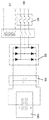
도 3은 전해 셀들을 세척하기 위하여(바람직하게는 짧은 시간 동안 및/또는 낮은 전류들에서) 극성을 반전시키기 위한 H-브릿지 구성으로 배열된 접촉기들(예를 들어, 스위치들 및/또는 릴레이들)을 포함하는 본 발명의 다른 실시예의 개략도이다. 유입되는 AC 전원(110)은 접촉기 컨트롤(120)을 경유하여 퓨즈(130), 다이오드 정류기(140) 및 필터 커패시터(145)를 거쳐서 통과되며, 그 후에 양극 셀 또는 복수의 전해 셀들(150)에 인가된다. 릴레이들(151, 152, 153, 154)은 바람직하게는 H-브릿지 구성으로 배열되고, 순방향 극성 신호(forward polarity signal)(156) 및 역방향 극성 신호(reverse polarity signal)(158)에 의하여 제어된다. Figure 3 shows contactors (e.g., switches and / or relays) arranged in an H-bridge configuration for reversing the polarity (preferably for short periods of time and / or at low currents) ) ≪ / RTI > of the present invention. The incoming
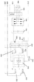
도 4의 회로는 도 3의 구성에 더하여 벅 컨버터를 사용한다. 유입되는 AC 전원(160)은 접촉기 컨트롤(170)을 경유하여 퓨즈(180), 다이오드 정류기(190) 및 필터 커패시터(195)을 거쳐서 통과되며, 그 후에 양극 셀 또는 복수의 전해 셀들(200)에 인가된다. 릴레이들(201, 202, 203, 204)은 바람직하게는 H-브릿지 구성으로 배열되고, 순방향 극성 신호(206) 및 역방향 극성 신호(208)에 의하여 제어된다. MOSFET 스위치(220)의 펄스 폭 변조(Pulse Width Modulation, PWM) 신호(210) 변경에 의하여 벅 컨버터는 정류된 주 전원(mains)로부터 전압 감압를 위한 효율적인 방법을 제공한다. 또한 벅 컨버터는 바람직하게는 다이오드(230), 필터 커패시터(240) 및 인덕터(inductor)(250)를 포함한다.The circuit of Fig. 4 uses a buck converter in addition to the configuration of Fig. The incoming
기존 시스템들에서 일반적인 것과 같이, 벅 컨버터 또는 비슷한 회로를 사용하는 것은 전압 감압를 위해 변압기를 사용하는 것에 비하여 어떤 장점들을 가진다. 첫째, 전압은 사용자에 의하여 요구되는 전기-화학을 위하여 적절하게 선택될 수 있다. 즉, 전극마다 다른 전압들을 사용함에 의하여, 다른 화학적 성질들이 달성될 수 있다. 예를 들면, 수소 생산이 증대되거나 감소될 수 있고, 과산화수소 보다 차아염소산염 생산이 더 선호될 수 있다(또는 그 반대).As is common in existing systems, using a buck converter or similar circuit has certain advantages over using a transformer for voltage depression. First, the voltage can be appropriately selected for the electrochemistry required by the user. That is, by using different voltages for each electrode, other chemical properties can be achieved. For example, hydrogen production may be increased or decreased, and hypochlorite production may be preferred over hydrogen peroxide (or vice versa).
둘째, 본 발명은 전 세계에 걸쳐 발견되는 다른 전원 전압들을 위하여 더 쉽게 보정할 수 있다. 국제적 시장을 위한 제조 산업 장비는 다른 AC 주 전원 전압들을 활용하기 위한 장비를 요구한다. 전 세계에 걸쳐 3상 전원(three phase power)은 50-60Hz에서 208, 220, 230, 240, 346, 380, 400, 415, 480, 600 또는 690 VAC의 임의의 것일 수 있다. 보통 이는 전압들의 특정한 범위를 위하여 설계된 특별한 변압기들 또는 특정 설정 전압에서 셀 라인의 동작을 위하여 설계된 일반 변압기와 함께 사용된 승압/감압 변압기들을 요구한다. 전형적인 예시는 480 VAC 주 전원과 42 VDC를 생산하는 정류된 보조 전원을 활용하기 위해 주로 설계된 변압기이다. 만약 이 변압기가 380 VAC 주 전원에 연결되었다면, 정류된 출력은 셀 라인을 드라이브하기 위해서는 너무 낮은 33.3 VDC이다. 적어도 동일한 전력 소비량 및 대략의 크기의 승압변압기는 일반 시스템에 더하여 현장에 설치될 것을 요구한다. 이는 실질적으로 설치된 시스템의 전체 비용 및 공간을 증가시킬 수 있다. 또한 두 변압기들의 결합 손실들 때문에 전반적 전원 효율의 감소가 있다.Second, the present invention can be more easily corrected for other power supply voltages found throughout the world. Manufacturing industry equipment for international markets requires equipment to utilize other AC mains voltages. The three phase power across the world can be any of 208, 220, 230, 240, 346, 380, 400, 415, 480, 600 or 690 VAC at 50-60 Hz. This usually requires special transformers designed for a specific range of voltages or step-up / step-down transformers used with a generic transformer designed for operation of the cell line at a certain set voltage. A typical example is a transformer designed primarily to take advantage of a 480 VAC mains supply and a rectified auxiliary supply producing 42 VDC. If this transformer is connected to a 380 VAC mains supply, the rectified output is 33.3 VDC too low to drive the cell line. At least the same power consumption and about the size of the step-up transformer require to be installed on site in addition to the general system. This can substantially increase the overall cost and space of the installed system. There is also a reduction in overall power efficiency due to coupling losses of the two transformers.
셋째, 만약 바닷물이 시스템에 단독의 염수 공급 원료로 사용되는 경우, 바닷물의 전도도는 염분 및 온도에 의하여 다양하고 일정하지 않으므로, 전원 공급은 바닷물의 전도도에 따라 동적으로 조정되어야만 한다. 벅 구성(buck configuration)은 전압 대신에 전류 피드백을 사용할 수 있고, 따라서 대신 정전류전원(constant current source)이 된다. 이는 변압기를 사용하여서는 구현하기 어렵거나 불가능하다.Third, if seawater is used as the sole salt water feedstock in a system, the conductivity of the seawater varies and varies with salinity and temperature, so the power supply must be dynamically adjusted according to the conductivity of the seawater. The buck configuration can use current feedback instead of voltage, and thus becomes a constant current source. This is difficult or impossible to implement using a transformer.
예컨대 벅 컨버터를 포함하는 변압기 없는 회로 때문에, 일반적으로 정류된 라인 전압의 100% 이상을 감압할 수 없고(그리고 일반적으로 미만, 예컨대 80% 미만, 50% 미만, 25% 미만 또는 심지어 20% 미만), 전해 셀 또는 셀들이 어떠한 전압 조정 없이 정류된 라인 전압에 가깝게 조정하도록 설계되는 것이 바람직하다. 다시 말해서, 셀 또는 셀들은 바람직하게는 시스템으로 하여금 정확하게 또는 선택적으로 단지 일부 백분율로, 각 셀에서 원하는 플레이트 간 전압에서 동작하기 위한 정류된 라인 전압의 전압 조정과 함께 동작하도록 하기 위한 다수의 중간 전극들과 함께 구성된다. 이는 일반적으로 셀 또는 셀들이 기술분야에서 일반적인 셀들보다 훨씬 높은 전반적인 전압에서 동작하는 것과, 일반적으로 원하는 플레이트 간 전압을 달성하기 위하여 더 많은 수의 중간 전극들을 포함하는 것을 의미한다. 다수의 셀들에 대하여 이는 셀들이 병렬보다 직렬로 배열되었을 때 성취하기 쉽다.(And generally less than, for example, less than 80%, less than 50%, less than 25%, or even less than 20%) of 100% or more of the rectified line voltage because of the transformerless circuitry, , It is desirable that the electrolytic cells or cells are designed to be adjusted close to the rectified line voltage without any voltage regulation. In other words, the cell or cells preferably have a plurality of intermediate electrodes for operating the system with voltage regulation of the rectified line voltage to operate at exactly the desired inter-plate voltage in each cell, Lt; / RTI > This generally means that the cell or cells operate at a much higher overall voltage than cells common in the art and generally include a greater number of intermediate electrodes to achieve the desired inter-plate voltage. For multiple cells, this is likely to be achieved when the cells are arranged in series rather than in parallel.
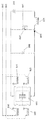
도 5에서 본 발명의 다른 실시예가 보여진다. 부스트 컨버터는 배터리(310)으로부터 셀(바람직하게는 양극의) 또는 셀 라인(320)을 드라이브하기에 적절한 전압까지 낮은 전압을 승압하기 위해 사용된다. 부스트 컨버터는 바람직하게는 PWM 신호(300)을 경유하여 동작되고, 인덕터(330), 다이오드(340)과 MOSFET(350)을 포함한다. 선택적인 필터 커패시터(360)은 전압을 평활하게 한다. 릴레이들(370, 375, 380, 385)은 바람직하게는 H-브릿지 구성으로 배열되고, 순방향 극성 신호(390) 및 역방향 극성 신호(395)에 의하여 제어된다. 이 구성은 예를 들면 단지 약간의 태양 전지 또는 작은 휴대용 물 취급 장비를 가동하기 위해 사용될 수 있는 작은 인력 발전기들으로부터 에너지를 수확(harvest)하기 위한 방법을 제공한다. 또한 이 구성은 태양 전지판의 출력을 요구되는 셀 라인에 대한 더 나은 매칭에 의하여 광전지 에너지 발전을 활용하는 더 많은 공공시설을 이용하지 않는(off the grid) 적용들에 최적화하기 위해 사용될 수 있다.
5 shows another embodiment of the present invention. The boost converter is used to boost the low voltage from the
예시example
5 볼트의 셀 전압과 함께 하루에 염소 5 파운드를 생산하는 능력이 있는 단일의 단극(두 전극들)은 100 암페어의 셀 전류를 요구한다. 표 1에서, 5 파운드 시스템이 480 볼트 삼상 입력(VAC)와 함께 하루에 염소 675 파운드를 생산하도록 세 가지 다른 구성들로 규모를 키웠다. 따라서 정류된 라인 전원은 약 672V 였다. 각 구성을 위한 플레이트 간 전압은 5 볼트였다. 처음 두 가지 구성들은 통상적인 방법들을 사용한다. 마지막 하나는 유입되는 사용가능한 전원에 매칭된 직렬 셀 접근(셀들이 직렬로 연결된다)을 사용한다. 이 경우에서 만약 N = 3이면, 각각 45 챔버들(chambers)과 함께 셀 라인에서 세 개의 전해 셀들을 가진다.A single unipolar (two electrodes) capable of producing 5 pounds of chlorine per day with a cell voltage of 5 volts requires a cell current of 100 amps. In Table 1, the 5-pound system was scaled up to three different configurations to produce 675 pounds of chlorine per day with a 480-volt three-phase input (VAC). Therefore, the rectified line power was about 672V. The voltage across the plate for each configuration was 5 volts. The first two configurations use conventional methods. The last one uses serial cell access (the cells are connected in series) matched to the incoming available power. In this case, if N = 3, we have three electrolytic cells in the cell line with 45 chambers each.
(킬로와트)Incoming power
(kilowatt)
(VDC)Cell voltage
(VDC)
(Amps)Cell current
(Amps)
(파운드)Transformer weight
(pound)
(평방 인치)Cell Bus Bar Size
(Square inch)
비록 본 발명이 개시된 실시예에 관한 특정한 참조와 함께 상세히 기재되었지만, 다른 실시예들도 동일한 결과를 달성할 수 있다. 본 발명의 변형들 및 수정들은 통상의 기술자에게 분명해질 것이고, 본 발명은 모든 그러한 수정들 및 균등물들을 포함시키기 위해 의도된다. 상기 인용된 모든 특허들 및 게시물의 전체 개시내용은 본 명세서에 참조로 통합된다.Although the present invention has been described in detail with specific reference to the disclosed embodiments, other embodiments may achieve the same result. Variations and modifications of the present invention will become apparent to those of ordinary skill in the art, and the present invention is intended to include all such modifications and equivalents. The entire disclosures of all patents and publications cited above are incorporated herein by reference.
Claims (24)
인접한 중간 전극들 사이에 원하는 플레이트 간 전압(desired plate to plate voltage)을 유지하면서 상기 장치로 하여금 정류된 라인 전압(rectified line voltage)의 단지 일부 백분율 내에서 동작하도록 하기에 충분한 다수의 중간 전극들을 포함하는 하나 이상의 전해 셀들(electrolytic cells)을 포함하며, 상기 장치는 변압기를 포함하지 않는 것을 특징으로 하는 장치.In the apparatus,
Includes a plurality of intermediate electrodes sufficient to allow the device to operate within only a fraction of the rectified line voltage while maintaining a desired plate to plate voltage between adjacent intermediate electrodes Wherein the device comprises one or more electrolytic cells, wherein the device does not include a transformer.
상기 장치는 대략적으로 상기 정류된 라인 전압에서 동작하도록 되어있고, 상기 장치는 어떠한 전압 조정도 포함하지 않는 것을 특징으로 하는 장치.The method according to claim 1,
Wherein the device is adapted to operate at approximately the rectified line voltage, and wherein the device does not comprise any voltage regulation.
상기 장치는 벅 컨버터 회로(buck converter circuit) 또는 부스트 컨버터 회로(boost converter circuit)에 의하여 제공되는 전압 조정을 포함하는 것을 특징으로 하는 장치.The method according to claim 1,
Wherein the apparatus comprises voltage regulation provided by a buck converter circuit or a boost converter circuit.
상기 전압 조정은 상기 하나 이상의 전해 셀들 양단의 전압을 상기 정류된 라인 전압의 약 80%까지 변화시킬 수 있는 것을 특징으로 하는 장치.The method of claim 3,
Wherein the voltage adjustment is capable of varying the voltage across the one or more electrolytic cells to about 80% of the rectified line voltage.
상기 전압 조정은 상기 하나 이상의 전해 셀들 양단의 전압을 상기 정류된 라인 전압의 약 50%까지 변화시킬 수 있는 것을 특징으로 하는 장치.5. The method of claim 4,
Wherein the voltage adjustment is capable of varying the voltage across the one or more electrolytic cells to about 50% of the rectified line voltage.
상기 전압 조정은 상기 하나 이상의 전해 셀들 양단의 전압을 상기 정류된 라인 전압의 약 25%까지 변화시킬 수 있는 것을 특징으로 하는 장치.6. The method of claim 5,
Wherein the voltage adjustment is capable of varying the voltage across the one or more electrolytic cells to about 25% of the rectified line voltage.
상기 전압 조정은 상기 하나 이상의 전해 셀들 양단의 전압을 상기 정류된 라인 전압의 약 20%까지 변화시킬 수 있는 것을 특징으로 하는 장치.The method according to claim 6,
Wherein the voltage adjustment is capable of varying the voltage across the one or more electrolytic cells by about 20% of the rectified line voltage.
상기 복수의 전해 셀들이 직렬로 연결되는 것을 특징으로 하는 장치.The method according to claim 1,
Wherein the plurality of electrolytic cells are connected in series.
상기 장치는 상기 하나 이상의 전해 셀들의 자가 세척을 가능하게 하기 위하여 상기 하나 이상의 전해 셀들의 극성을 반전시키기 위한 H-브릿지(H-bridge) 구성으로 복수의 접촉기들(contactors)을 더 포함하는 것을 특징으로 하는 장치.The method according to claim 1,
The apparatus further comprises a plurality of contactors in an H-bridge configuration for reversing the polarity of the one or more electrolytic cells to enable self-cleaning of the one or more electrolytic cells .
유입되는 라인 전압을 정류하는 단계;
인접한 중간 전극들 사이에 원하는 플레이트 간 전압을 유지하면서 하나 이상의 전해 셀들로 하여금 정류된 라인 전압의 단지 일부 백분율 내에서 동작하도록 하기에 충분한 다수의 중간 전극들을 포함하는 하나 이상의 전해 셀들을 제공하는 단계; 및
정류된 라인 전압을 변화시키지 않거나 또는, 상기 정류된 라인 전압을 변압기를 사용함 없이 변화시키는 단계를 포함하는 것을 특징으로 하는 전기 분해 수행 방법.A method for performing electrolysis,
Rectifying the incoming line voltage;
Providing at least one electrolytic cell comprising a plurality of intermediate electrodes sufficient to maintain the desired inter-plate voltage between adjacent intermediate electrodes while allowing the one or more electrolytic cells to operate within only a fraction of the rectified line voltage; And
Wherein the step of changing the rectified line voltage comprises changing the rectified line voltage or changing the rectified line voltage without using a transformer.
상기 다수의 중간 전극들이 상기 하나 이상의 전해 셀들로 하여금 대략 상기 정류된 라인 전압에서 동작하도록 하기에 충분하기 때문에, 상기 정류된 전압은 변화되지 않는 것을 특징으로 하는 방법.11. The method of claim 10,
Wherein the rectified voltage is not changed because the plurality of intermediate electrodes is sufficient to cause the one or more electrolytic cells to operate at approximately the rectified line voltage.
상기 정류된 라인 전압을 변화(variation)시키는 단계는 벅 컨버터 회로 또는 부스트 컨버터 회로를 사용하여 수행되는 것을 특징으로 하는 방법.11. The method of claim 10,
Wherein the step of varying the rectified line voltage is performed using a buck converter circuit or a boost converter circuit.
상기 정류된 라인 전압을 변화시키는 단계는 하나 이상의 전해 셀들 양단의 전압을 상기 정류된 라인 전압의 약 80%까지 변화시키는 단계를 포함하는 것을 특징으로 하는 방법.13. The method of claim 12,
Wherein changing the rectified line voltage comprises varying a voltage across one or more electrolytic cells to about 80% of the rectified line voltage.
상기 정류된 라인 전압을 변화시키는 단계는 하나 이상의 전해 셀들 양단의 전압을 상기 정류된 라인 전압의 약 50%까지 변화시키는 단계를 포함하는 것을 특징으로 하는 방법.14. The method of claim 13,
Wherein changing the rectified line voltage comprises varying a voltage across one or more electrolytic cells to about 50% of the rectified line voltage.
상기 정류된 라인 전압을 변화시키는 단계는 하나 이상의 전해 셀들 양단의 전압을 상기 정류된 라인 전압의 약 25%까지 변화시키는 단계를 포함하는 것을 특징으로 하는 방법.15. The method of claim 14,
Wherein changing the rectified line voltage comprises varying a voltage across one or more electrolytic cells to about 25% of the rectified line voltage.
상기 정류된 라인 전압을 변화시키는 단계는 하나 이상의 전해 셀들 양단의 전압을 상기 정류된 라인 전압의 약 20%까지 변화시키는 단계를 포함하는 것을 특징으로 하는 방법.16. The method of claim 15,
Wherein changing the rectified line voltage comprises varying the voltage across one or more electrolytic cells to about 20% of the rectified line voltage.
상기 정류된 라인 전압을 변화시키는 단계는 상기 유입되는 라인 전압의 변동들을 조정(accommodation)하는 것을 특징으로 하는 방법.11. The method of claim 10,
Wherein varying the rectified line voltage comprises accommodating variations in the incoming line voltage.
상기 정류된 라인 전압을 변화시키는 단계는 하나 이상의 전해 셀들에 의하여 생산된 화학 제품들을 변경하는 것을 특징으로 하는 방법.11. The method of claim 10,
Wherein changing the rectified line voltage alters the chemicals produced by the one or more electrolytic cells.
상기 화학 제품들은 수소의 양 및 차아염소산염 대 과산화수소의 비로 구성되는 그룹으로부터 선택되는 것을 특징으로 하는 방법.19. The method of claim 18,
Wherein the chemical products are selected from the group consisting of the amount of hydrogen and the ratio of hypochlorite to hydrogen peroxide.
상기 정류된 라인 전압을 변화시키는 단계는 변화하는 전해액의 전도도를 조정하는 단계를 포함하는 것을 특징으로 하는 방법.11. The method of claim 10,
Wherein the step of varying the rectified line voltage comprises adjusting the conductivity of the varying electrolyte.
상기 전해액은 바닷물을 포함하며, 상기 바닷물의 전도도는 염분 및/또는 바닷물의 온도의 변동들 때문에 변화하는 것을 특징으로 하는 방법.21. The method of claim 20,
Wherein the electrolytic solution comprises seawater and the conductivity of the seawater changes due to variations in the temperature of the saline and / or seawater.
복수의 전해 셀들을 직렬로 연결하는 단계를 포함하는 것을 특징으로 하는 방법.11. The method of claim 10,
And connecting the plurality of electrolytic cells in series.
하나 이상의 전해 셀들이 자가 세척되도록, H-브릿지(H-bridge) 구성으로 복수의 접촉기들을 사용하여 하나 이상의 전해 셀들의 극성을 반전시키는 단계를 더 포함하는 것을 특징으로 하는 방법.11. The method of claim 10,
Further comprising reversing the polarity of one or more electrolytic cells using a plurality of contactors in an H-bridge configuration such that one or more electrolytic cells are self-cleaning.
상기 부스트 컨버터 회로를 사용하는 정류된 라인 전압을 변화시키는 단계는 낮은 전압 전원 소스로부터 에너지를 수확(harvest)하는 단계 또는 하나 이상의 전해 셀들 양단의 원하는 전압에 태양 전지 출력을 매칭시키는 단계를 포함하는 것을 특징으로 하는 방법.13. The method of claim 12,
The step of varying the rectified line voltage using the boost converter circuit may include harvesting energy from a low voltage power source or matching the solar cell output to a desired voltage across one or more electrolytic cells Lt; / RTI >
Priority Applications (1)
| Application Number | Priority Date | Filing Date | Title |
|---|---|---|---|
| KR1020217038882A KR20210147116A (en) | 2012-10-05 | 2013-10-07 | Transformerless on-site generation |
Applications Claiming Priority (3)
| Application Number | Priority Date | Filing Date | Title |
|---|---|---|---|
| US201261710468P | 2012-10-05 | 2012-10-05 | |
| US61/710,468 | 2012-10-05 | ||
| PCT/US2013/063743 WO2014055992A1 (en) | 2012-10-05 | 2013-10-07 | Transformerless on-site generation |
Related Child Applications (1)
| Application Number | Title | Priority Date | Filing Date |
|---|---|---|---|
| KR1020217038882A Division KR20210147116A (en) | 2012-10-05 | 2013-10-07 | Transformerless on-site generation |
Publications (1)
| Publication Number | Publication Date |
|---|---|
| KR20150067760A true KR20150067760A (en) | 2015-06-18 |
Family
ID=50431876
Family Applications (2)
| Application Number | Title | Priority Date | Filing Date |
|---|---|---|---|
| KR1020157011760A KR20150067760A (en) | 2012-10-05 | 2013-10-07 | Transformerless on-site generation |
| KR1020217038882A KR20210147116A (en) | 2012-10-05 | 2013-10-07 | Transformerless on-site generation |
Family Applications After (1)
| Application Number | Title | Priority Date | Filing Date |
|---|---|---|---|
| KR1020217038882A KR20210147116A (en) | 2012-10-05 | 2013-10-07 | Transformerless on-site generation |
Country Status (9)
| Country | Link |
|---|---|
| US (1) | US20140097093A1 (en) |
| EP (1) | EP2904689B1 (en) |
| JP (1) | JP2015537116A (en) |
| KR (2) | KR20150067760A (en) |
| CA (1) | CA2926075C (en) |
| ES (1) | ES2934683T3 (en) |
| PT (1) | PT2904689T (en) |
| SG (1) | SG11201502269WA (en) |
| WO (1) | WO2014055992A1 (en) |
Families Citing this family (8)
| Publication number | Priority date | Publication date | Assignee | Title |
|---|---|---|---|---|
| JP6230451B2 (en) * | 2014-03-11 | 2017-11-15 | 株式会社東芝 | Photochemical reaction apparatus and chemical reaction apparatus |
| KR102578933B1 (en) * | 2017-03-06 | 2023-09-14 | 에보쿠아 워터 테크놀로지스 엘엘씨 | Pulse power supply for sustainable redox material supply for hydrogen reduction during electrochemical hypochlorite generation |
| EP3556905A1 (en) * | 2018-04-19 | 2019-10-23 | Siemens Aktiengesellschaft | Circuit arrangement, method for operating a circuit arrangement and electrolysis device |
| US11699972B2 (en) * | 2018-08-24 | 2023-07-11 | Johnson Controls Tyco IP Holdings LLP | Variable speed motor drive with integrated motor heating systems and methods |
| FR3105266B1 (en) * | 2019-12-19 | 2021-11-19 | Air Liquide | Combination of power electronics systems regulated by harmonic filtration and / or reactive power compensation supplying a controlled unit for the production of hydrogen and oxygen by electrolysis of water |
| US11352703B2 (en) * | 2020-06-10 | 2022-06-07 | The Florida International University Board Of Trustees | Bipolar exfoliation and in-situ deposition of high-quality reduced graphene |
| WO2023107607A1 (en) * | 2021-12-08 | 2023-06-15 | Electric Hydrogen Co | Variable inverter based power control |
| WO2024075239A1 (en) * | 2022-10-06 | 2024-04-11 | 東芝三菱電機産業システム株式会社 | Power supply device |
Family Cites Families (44)
| Publication number | Priority date | Publication date | Assignee | Title |
|---|---|---|---|---|
| US3616355A (en) * | 1968-08-05 | 1971-10-26 | Kdi Chloro Guard Corp | Method of generating enhanced biocidal activity in the electroylsis of chlorine containing solutions and the resulting solutions |
| CA914610A (en) * | 1970-06-26 | 1972-11-14 | Chemetics International Ltd. | Multi-monopolar electrolytic cell assembly and system |
| US3942104A (en) * | 1974-05-03 | 1976-03-02 | Engelhard Minerals & Chemicals Corporation | Cell balance detector for electrolytic cell assemblies |
| US4085028A (en) * | 1974-11-21 | 1978-04-18 | Electro-Chlor Corporation | Electrolytic chlorination device |
| JPS5914555B2 (en) * | 1975-03-31 | 1984-04-05 | 旭化成株式会社 | How to supply power to the electrolytic cell |
| US4100052A (en) * | 1976-11-11 | 1978-07-11 | Diamond Shamrock Corporation | Electrolytic generation of halogen biocides |
| US4235694A (en) * | 1978-10-06 | 1980-11-25 | Hall Frederick F | Electrolytic cells for hydrogen gas production |
| US4316787A (en) * | 1979-08-06 | 1982-02-23 | Themy Constantinos D | High voltage electrolytic cell |
| US4236992A (en) * | 1979-08-06 | 1980-12-02 | Themy Constantinos D | High voltage electrolytic cell |
| JPS586789B2 (en) * | 1980-01-22 | 1983-02-07 | 旭硝子株式会社 | Method for preventing deterioration of palladium oxide anodes |
| US4248690A (en) * | 1980-01-28 | 1981-02-03 | Pennwalt Corporation | Apparatus for production of sodium hypochlorite |
| GB2081743B (en) * | 1980-07-31 | 1984-06-27 | Spirig Ernst | Cooling electrolysis apparatus generating gases |
| US4372827A (en) * | 1980-11-10 | 1983-02-08 | Panclor S.A. | Novel horizontal diaphragmless electrolyzer |
| US4395675A (en) * | 1981-10-22 | 1983-07-26 | Bell Telephone Laboratories, Incorporated | Transformerless noninverting buck boost switching regulator |
| JPS58110685A (en) * | 1981-12-25 | 1983-07-01 | インスチツ−ト・エレクトロスワルキ・イメ−ニ・イ−・オ−・パト−ナ・アカデミ−・ナウク・ウクラインスコイ・エスエスエル | Filterpress type electrolytic cell for manufacturing mixture of hydrogen and oxygen |
| US4424105A (en) * | 1982-08-05 | 1984-01-03 | Henes Products Corp. | Gas generator with regulated current source |
| AU619050B2 (en) * | 1988-10-11 | 1992-01-16 | Sal-Chlor Pty. Ltd. | Improvements in pool chlorinators |
| JPH03150383A (en) * | 1989-11-08 | 1991-06-26 | Japan Carlit Co Ltd:The | Filter press type bipolar electrolyzer |
| US5130006A (en) * | 1989-11-09 | 1992-07-14 | Oligny Louis Andre | Pyramidal shaped electrolysis cell |
| JPH0413881A (en) * | 1990-05-02 | 1992-01-17 | Japan Carlit Co Ltd:The | Filter press type bipolar electrolyzer |
| US5254226A (en) * | 1992-05-05 | 1993-10-19 | Ad Rem Manufacturing, Inc. | Electrolytic cell assembly and process for production of bromine |
| JPH07242402A (en) * | 1994-03-02 | 1995-09-19 | Sasakura Eng Co Ltd | Water-electrolysis ozonizer |
| US5795459A (en) * | 1996-07-29 | 1998-08-18 | Sweeney; Charles T. | Apparatus and method for water purification |
| US6217741B1 (en) * | 1998-10-13 | 2001-04-17 | Morinaga Engineering Co., Ltd. | Method for manufacturing bactericide |
| US6198257B1 (en) * | 1999-10-01 | 2001-03-06 | Metropolitan Industries, Inc. | Transformerless DC-to-AC power converter and method |
| JP3414720B2 (en) * | 2001-02-02 | 2003-06-09 | 神鋼パンテツク株式会社 | Water electrolysis device |
| TW547489U (en) * | 2001-09-14 | 2003-08-11 | Shihlin Electric & Engineering | Hydrogen oxygen generation device with insertion type electrolytic tank |
| US6740436B2 (en) * | 2002-08-22 | 2004-05-25 | Natural Energy Resources | Hydrogen/oxygen generating system with temperature control |
| US7625470B2 (en) * | 2004-04-13 | 2009-12-01 | Whirlpool Corporation | Electrolytic chemical generator for automatic cleaning device |
| JP2005350716A (en) * | 2004-06-10 | 2005-12-22 | Wakamiya Kogyo Kk | Electrolytic sterilization device for tank |
| US20060114642A1 (en) * | 2004-11-30 | 2006-06-01 | Yan Liu | Systems and methods for integrated VAR compensation and hydrogen production |
| US7996171B2 (en) * | 2005-01-27 | 2011-08-09 | Electro Industries/Gauge Tech | Intelligent electronic device with broad-range high accuracy |
| KR101323046B1 (en) * | 2005-08-16 | 2013-10-29 | 엠케이에스 인스트루먼츠, 인코포레이티드 | Load resonant type power supply for ozonizer |
| TW200709544A (en) * | 2005-08-29 | 2007-03-01 | Ind Tech Res Inst | Transformer-free power conversion circuit for parallel connection with commercial electricity system |
| US8007654B2 (en) * | 2006-02-10 | 2011-08-30 | Tennant Company | Electrochemically activated anolyte and catholyte liquid |
| US8025787B2 (en) * | 2006-02-10 | 2011-09-27 | Tennant Company | Method and apparatus for generating, applying and neutralizing an electrochemically activated liquid |
| JP4872393B2 (en) * | 2006-03-14 | 2012-02-08 | 株式会社日立製作所 | Wind power generation hydrogen production system |
| CN101495811A (en) * | 2006-05-01 | 2009-07-29 | 克罗普利控股有限公司 | Method and equipment for cooking by using combustible gas generated by electric tank |
| AU2008273918B2 (en) * | 2007-07-07 | 2011-09-29 | Itm Power (Research) Ltd. | Electrolysis of salt water |
| US20090205972A1 (en) * | 2008-01-04 | 2009-08-20 | Miox Corporation | Electrolytic Purifier |
| WO2009155044A2 (en) * | 2008-05-28 | 2009-12-23 | Miox Corporation | Reverse polarity cleaning and electronic flow control systems for low intervention electrolytic chemical generators |
| BRPI0922167A2 (en) * | 2008-12-17 | 2019-09-24 | Tennant Co | apparatus for applying electric charge through a liquid, method for applying electric charge through a liquid, and antimicrobial medium |
| US8058752B2 (en) * | 2009-02-13 | 2011-11-15 | Miasole | Thin-film photovoltaic power element with integrated low-profile high-efficiency DC-DC converter |
| JP2011249161A (en) * | 2010-05-27 | 2011-12-08 | Aquafairy Kk | Power generator |
-
2013
- 2013-10-07 ES ES13843748T patent/ES2934683T3/en active Active
- 2013-10-07 CA CA2926075A patent/CA2926075C/en active Active
- 2013-10-07 EP EP13843748.8A patent/EP2904689B1/en active Active
- 2013-10-07 SG SG11201502269WA patent/SG11201502269WA/en unknown
- 2013-10-07 KR KR1020157011760A patent/KR20150067760A/en not_active IP Right Cessation
- 2013-10-07 KR KR1020217038882A patent/KR20210147116A/en not_active Application Discontinuation
- 2013-10-07 US US14/047,934 patent/US20140097093A1/en not_active Abandoned
- 2013-10-07 PT PT138437488T patent/PT2904689T/en unknown
- 2013-10-07 JP JP2015535877A patent/JP2015537116A/en active Pending
- 2013-10-07 WO PCT/US2013/063743 patent/WO2014055992A1/en active Application Filing
Also Published As
| Publication number | Publication date |
|---|---|
| CA2926075A1 (en) | 2014-04-10 |
| SG11201502269WA (en) | 2015-04-29 |
| EP2904689B1 (en) | 2022-11-30 |
| US20140097093A1 (en) | 2014-04-10 |
| ES2934683T3 (en) | 2023-02-24 |
| JP2015537116A (en) | 2015-12-24 |
| PT2904689T (en) | 2023-01-03 |
| EP2904689A4 (en) | 2016-02-10 |
| WO2014055992A1 (en) | 2014-04-10 |
| EP2904689A1 (en) | 2015-08-12 |
| CA2926075C (en) | 2023-02-14 |
| KR20210147116A (en) | 2021-12-06 |
Similar Documents
| Publication | Publication Date | Title |
|---|---|---|
| EP2904689B1 (en) | Transformerless on-site generation | |
| EP1728413B1 (en) | Lamp driver using solar cells | |
| US10006132B2 (en) | Electrolysis stack and electrolyzer | |
| RU2013114728A (en) | ELECTRIC POWER SUPPLY DEVICE FOR DRIVE DEVICES OF RAIL VEHICLES | |
| US20130264876A1 (en) | Inverter assembly and solar power plant comprising the same | |
| US11606043B2 (en) | Balanced capacitor power converter | |
| CN110635510B (en) | Cooperative control method for non-grid-connected wind power water electrolysis hydrogen production system | |
| RU2007114964A (en) | ARC FURNITURE DEVICE | |
| JP2022551402A (en) | Systems and methods for electrochemical processes | |
| CN102148566A (en) | Boost-type voltage balance converter | |
| EP1844539B1 (en) | Method and inverter for converting a dc voltage into a 3-phase ac output | |
| KR20210022540A (en) | Electric deionization device, ultrapure water production system, and ultrapure water production method | |
| JP2024502382A (en) | Power conversion system for electrolytic stack | |
| TW200743295A (en) | A control method and apparatus of resonant type DC/DC converter with low power loss at standby | |
| JP3539458B2 (en) | Power supply for electrolyzed water generator | |
| CN114032559B (en) | New energy off-grid hydrogen production system and method | |
| RU2368051C1 (en) | Reactive power compensation device | |
| CN105305837B (en) | Single-phase and three-phase-inversion chopper power transformer compensation AC voltage-stabilized power supply | |
| Kasari et al. | An improved grid integration technique for SPV-based CHB-MLI in distribution network | |
| KR101444243B1 (en) | Apparatus for the efficient management of electrical energy by the superposition of DC voltage or current for electrolysis apparatus | |
| CN117321901A (en) | Method for operating a DC regulator for supplying an electrolysis device with electrical operating energy | |
| Jung et al. | Study On Photovoltaic Module Integrated Converter based on Active Clamp Current-fed Half-Bridge Converter | |
| Neba et al. | Utility Interactive Operations of PWM Current Source Inverter-Induction Motor System with Photovoltaic Generation | |
| KR20160041639A (en) | Single phase inverter device | |
| KR101555217B1 (en) | Power supply of electrolysis water treatment system for a ship |
Legal Events
| Date | Code | Title | Description |
|---|---|---|---|
| N231 | Notification of change of applicant | ||
| A201 | Request for examination | ||
| N231 | Notification of change of applicant | ||
| E902 | Notification of reason for refusal | ||
| AMND | Amendment | ||
| E902 | Notification of reason for refusal | ||
| AMND | Amendment | ||
| E601 | Decision to refuse application | ||
| X091 | Application refused [patent] | ||
| AMND | Amendment | ||
| E902 | Notification of reason for refusal | ||
| AMND | Amendment | ||
| X601 | Decision of rejection after re-examination | ||
| J201 | Request for trial against refusal decision | ||
| J301 | Trial decision |
Free format text: TRIAL NUMBER: 2021101003032; TRIAL DECISION FOR APPEAL AGAINST DECISION TO DECLINE REFUSAL REQUESTED 20211126 Effective date: 20220330 |
|
| E902 | Notification of reason for refusal | ||
| E90F | Notification of reason for final refusal | ||
| S601 | Decision to reject again after remand of revocation |