KR20150052493A - Buried led lamp - Google Patents
Buried led lamp Download PDFInfo
- Publication number
- KR20150052493A KR20150052493A KR1020130133933A KR20130133933A KR20150052493A KR 20150052493 A KR20150052493 A KR 20150052493A KR 1020130133933 A KR1020130133933 A KR 1020130133933A KR 20130133933 A KR20130133933 A KR 20130133933A KR 20150052493 A KR20150052493 A KR 20150052493A
- Authority
- KR
- South Korea
- Prior art keywords
- reflector
- led
- pcb substrate
- base
- recessed
- Prior art date
Links
Images


Classifications
-
- F—MECHANICAL ENGINEERING; LIGHTING; HEATING; WEAPONS; BLASTING
- F21—LIGHTING
- F21K—NON-ELECTRIC LIGHT SOURCES USING LUMINESCENCE; LIGHT SOURCES USING ELECTROCHEMILUMINESCENCE; LIGHT SOURCES USING CHARGES OF COMBUSTIBLE MATERIAL; LIGHT SOURCES USING SEMICONDUCTOR DEVICES AS LIGHT-GENERATING ELEMENTS; LIGHT SOURCES NOT OTHERWISE PROVIDED FOR
- F21K9/00—Light sources using semiconductor devices as light-generating elements, e.g. using light-emitting diodes [LED] or lasers
- F21K9/20—Light sources comprising attachment means
- F21K9/23—Retrofit light sources for lighting devices with a single fitting for each light source, e.g. for substitution of incandescent lamps with bayonet or threaded fittings
- F21K9/235—Details of bases or caps, i.e. the parts that connect the light source to a fitting; Arrangement of components within bases or caps
-
- F—MECHANICAL ENGINEERING; LIGHTING; HEATING; WEAPONS; BLASTING
- F21—LIGHTING
- F21K—NON-ELECTRIC LIGHT SOURCES USING LUMINESCENCE; LIGHT SOURCES USING ELECTROCHEMILUMINESCENCE; LIGHT SOURCES USING CHARGES OF COMBUSTIBLE MATERIAL; LIGHT SOURCES USING SEMICONDUCTOR DEVICES AS LIGHT-GENERATING ELEMENTS; LIGHT SOURCES NOT OTHERWISE PROVIDED FOR
- F21K9/00—Light sources using semiconductor devices as light-generating elements, e.g. using light-emitting diodes [LED] or lasers
- F21K9/60—Optical arrangements integrated in the light source, e.g. for improving the colour rendering index or the light extraction
- F21K9/66—Details of globes or covers forming part of the light source
-
- F—MECHANICAL ENGINEERING; LIGHTING; HEATING; WEAPONS; BLASTING
- F21—LIGHTING
- F21K—NON-ELECTRIC LIGHT SOURCES USING LUMINESCENCE; LIGHT SOURCES USING ELECTROCHEMILUMINESCENCE; LIGHT SOURCES USING CHARGES OF COMBUSTIBLE MATERIAL; LIGHT SOURCES USING SEMICONDUCTOR DEVICES AS LIGHT-GENERATING ELEMENTS; LIGHT SOURCES NOT OTHERWISE PROVIDED FOR
- F21K9/00—Light sources using semiconductor devices as light-generating elements, e.g. using light-emitting diodes [LED] or lasers
- F21K9/60—Optical arrangements integrated in the light source, e.g. for improving the colour rendering index or the light extraction
- F21K9/68—Details of reflectors forming part of the light source
-
- F—MECHANICAL ENGINEERING; LIGHTING; HEATING; WEAPONS; BLASTING
- F21—LIGHTING
- F21S—NON-PORTABLE LIGHTING DEVICES; SYSTEMS THEREOF; VEHICLE LIGHTING DEVICES SPECIALLY ADAPTED FOR VEHICLE EXTERIORS
- F21S2/00—Systems of lighting devices, not provided for in main groups F21S4/00 - F21S10/00 or F21S19/00, e.g. of modular construction
- F21S2/005—Systems of lighting devices, not provided for in main groups F21S4/00 - F21S10/00 or F21S19/00, e.g. of modular construction of modular construction
-
- F—MECHANICAL ENGINEERING; LIGHTING; HEATING; WEAPONS; BLASTING
- F21—LIGHTING
- F21S—NON-PORTABLE LIGHTING DEVICES; SYSTEMS THEREOF; VEHICLE LIGHTING DEVICES SPECIALLY ADAPTED FOR VEHICLE EXTERIORS
- F21S8/00—Lighting devices intended for fixed installation
- F21S8/02—Lighting devices intended for fixed installation of recess-mounted type, e.g. downlighters
- F21S8/026—Lighting devices intended for fixed installation of recess-mounted type, e.g. downlighters intended to be recessed in a ceiling or like overhead structure, e.g. suspended ceiling
-
- F—MECHANICAL ENGINEERING; LIGHTING; HEATING; WEAPONS; BLASTING
- F21—LIGHTING
- F21V—FUNCTIONAL FEATURES OR DETAILS OF LIGHTING DEVICES OR SYSTEMS THEREOF; STRUCTURAL COMBINATIONS OF LIGHTING DEVICES WITH OTHER ARTICLES, NOT OTHERWISE PROVIDED FOR
- F21V17/00—Fastening of component parts of lighting devices, e.g. shades, globes, refractors, reflectors, filters, screens, grids or protective cages
- F21V17/10—Fastening of component parts of lighting devices, e.g. shades, globes, refractors, reflectors, filters, screens, grids or protective cages characterised by specific fastening means or way of fastening
- F21V17/12—Fastening of component parts of lighting devices, e.g. shades, globes, refractors, reflectors, filters, screens, grids or protective cages characterised by specific fastening means or way of fastening by screwing
-
- F—MECHANICAL ENGINEERING; LIGHTING; HEATING; WEAPONS; BLASTING
- F21—LIGHTING
- F21V—FUNCTIONAL FEATURES OR DETAILS OF LIGHTING DEVICES OR SYSTEMS THEREOF; STRUCTURAL COMBINATIONS OF LIGHTING DEVICES WITH OTHER ARTICLES, NOT OTHERWISE PROVIDED FOR
- F21V21/00—Supporting, suspending, or attaching arrangements for lighting devices; Hand grips
- F21V21/02—Wall, ceiling, or floor bases; Fixing pendants or arms to the bases
- F21V21/04—Recessed bases
- F21V21/041—Mounting arrangements specially adapted for false ceiling panels or partition walls made of plates
- F21V21/042—Mounting arrangements specially adapted for false ceiling panels or partition walls made of plates using clamping means, e.g. for clamping with panel or wall
-
- F—MECHANICAL ENGINEERING; LIGHTING; HEATING; WEAPONS; BLASTING
- F21—LIGHTING
- F21V—FUNCTIONAL FEATURES OR DETAILS OF LIGHTING DEVICES OR SYSTEMS THEREOF; STRUCTURAL COMBINATIONS OF LIGHTING DEVICES WITH OTHER ARTICLES, NOT OTHERWISE PROVIDED FOR
- F21V29/00—Protecting lighting devices from thermal damage; Cooling or heating arrangements specially adapted for lighting devices or systems
- F21V29/50—Cooling arrangements
- F21V29/70—Cooling arrangements characterised by passive heat-dissipating elements, e.g. heat-sinks
- F21V29/83—Cooling arrangements characterised by passive heat-dissipating elements, e.g. heat-sinks the elements having apertures, ducts or channels, e.g. heat radiation holes
-
- F—MECHANICAL ENGINEERING; LIGHTING; HEATING; WEAPONS; BLASTING
- F21—LIGHTING
- F21Y—INDEXING SCHEME ASSOCIATED WITH SUBCLASSES F21K, F21L, F21S and F21V, RELATING TO THE FORM OR THE KIND OF THE LIGHT SOURCES OR OF THE COLOUR OF THE LIGHT EMITTED
- F21Y2105/00—Planar light sources
- F21Y2105/10—Planar light sources comprising a two-dimensional array of point-like light-generating elements
-
- F—MECHANICAL ENGINEERING; LIGHTING; HEATING; WEAPONS; BLASTING
- F21—LIGHTING
- F21Y—INDEXING SCHEME ASSOCIATED WITH SUBCLASSES F21K, F21L, F21S and F21V, RELATING TO THE FORM OR THE KIND OF THE LIGHT SOURCES OR OF THE COLOUR OF THE LIGHT EMITTED
- F21Y2115/00—Light-generating elements of semiconductor light sources
- F21Y2115/10—Light-emitting diodes [LED]
Abstract
The present invention relates to a recessed (or downlight type) LED lighting apparatus with a simple structure which can easily replace a recessed incandescent lamp or a recessed fluorescent lamp such as a three-wavelength fluorescent lamp with an LED of high luminance and low power consumption, (4); A cylinder 5 connected to a lower portion of the base 4; A downwardly open reflecting reflector 6 fastened to the lower end 5b of the tubular body 5; A PCB substrate (7) installed inside the reflector (6); An LED lamp 8 which is arranged on the bottom surface of the PCB substrate 7 at predetermined intervals and is down-illuminated; A space 9 and a fastening member for maintaining a gap between the reflector 6 and the PCB substrate 7; A light diffusing cover (10) located under the reflector (6); A power supply unit 11 installed on the upper surface of the reflector 6 and supplying power supplied from the base 4 to the LED lamp 8; A closing member (12) fixed to the bottom of the reflector (6) and supporting the light diffusion cover (10); .
Description
The present invention relates to a recessed (or downlight type) LED lighting apparatus of a simple structure capable of easily replacing a buried incandescent lamp or a recessed fluorescent lamp (such as a three-wavelength fluorescent lamp) with an LED of high luminance and low power consumption.
Lighting can be classified into indoor lighting and outdoor lighting. Lighting devices for indoor lighting include an attachment type lighting device fixedly attached to a wall or a ceiling, and a stand type lighting device capable of moving a position freely . Typical examples of the attachment type lighting device include a lighting device in which a fluorescent lamp or an incandescent lamp is coupled to a bottom surface of a reflector that is fixed to a wall or a ceiling. As a living standard increases, As the desire for it grows, the appearance of the interior decoration is designed so that it can also serve as an interior decoration item rather than merely for illumination, so that the ceiling of a living room or a public place, (Or down-light) structure which does not have a built-in light source is installed.
Since the above-mentioned buried type illuminating device is provided with a luminaire embedded in a high-ceiling interior space, replacement works for installation work and repair are extremely inconvenient. Because of the spring-type fixing means used for fixing the lighting device to the ceiling, There is a problem that it is difficult to insert the ceiling cover into the ceiling opening or to remove it from the ceiling for maintenance, and in some cases, the ceiling is damaged.
In addition, since the incandescent lamp installed in the ceiling uses most incandescent lamps or three-wavelength lamps (or fluorescent lamps), which are much lower in luminous intensity and luminous intensity than the power consumption, replacement work is very inconvenient even when the lamp is replaced with a low- However, there is a problem that the size of the luminaire is not suitable, so that it is troublesome to rework according to the size of the LED lamp, and the ceiling is damaged when the LED lamp is replaced, or the height or size of the lighting device is not appropriate.
SUMMARY OF THE INVENTION Accordingly, the present invention has been made in view of the above problems, and it is an object of the present invention to provide a recessed (or downlight type) LED having a simple structure that can easily replace a recessed incandescent lamp or a recessed fluorescent lamp An illumination device is provided.
Another object of the present invention is to provide an LED lighting device with a recessed (or down-lighted) LED lighting device,
The recessed (or downlighted) LED lighting device of the present invention comprises: a
The present invention may further include a plurality of radiating holes (5a) formed in the cylinder (5).
In the present invention, the fastening of the
The present invention has the effect of easily replacing a conventional embedded type lighting device (luminaire) with an LED lighting device (luminaire) without damaging the ceiling.
INDUSTRIAL APPLICABILITY The present invention can be easily replaced by a high-luminance and low-power LED lighting device, so that not only the workability is easy, but also the electric energy can be saved.
The present invention is a very useful invention having an effect of appropriately adjusting the installation height of the recessed type LED lighting apparatus of the present invention in accordance with the installation height of a conventional embedding type lighting apparatus (luminaire).
1 is a cross-sectional view of an embodiment of the present invention;
2 is a sectional view showing another embodiment of the present invention.
3 is a cross-sectional view of another embodiment of the present invention.
4 is an exploded perspective view showing another embodiment of the present invention.
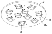
5 is a perspective view of a wiring LED lamp mounted on a PCB substrate in the present invention.
6: sectional view of the use state of the present invention.
Hereinafter, preferred embodiments of the present invention will be described in detail with reference to the accompanying drawings. DETAILED DESCRIPTION OF THE PREFERRED EMBODIMENTS In the following description of the embodiments of the present invention, the same components as in the drawings are denoted by the same reference numerals as possible, and detailed descriptions of known configurations and functions are omitted so as not to obscure the gist of the present invention. May be different from what is actually implemented with the schematized drawings in order to easily describe the embodiments of the present invention.
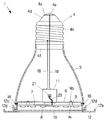
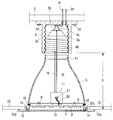
Fig. 1 is a cross-sectional view of a recessed
The
The
The
FIG. 1 is a perspective view of a
The insulating
A downwardly open reflecting
5, a plurality of
The reflection gathers 6 can be made of aluminum which is excellent in reflectivity, heat radiation and rigidity and is easy to manufacture. Of course, it is also possible to form the reflector by applying a reflective material to the surface after molding it with synthetic resins or other materials or by coating it.
The
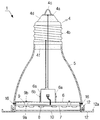
As shown in FIG. 4, a plurality of through-
The plurality of through-
Therefore, it is possible to appropriately adjust the installation height of the recessed type
Of course, when the difference in height h between the
The
The
The
An
A
A hollow 12b is formed at the center of the
The present invention can be used as a luminaire of a new facility, and can be used instead of a conventional buried type lighting device (luminaire). That is, after the conventional buried type lighting device (luminaire) is separated from the
The present invention can easily replace an existing embedded type lighting device (luminaire) with a high-luminance and low-power LED lighting device without breakage of the ceiling, so that it is easy to work and can save a great deal of electric energy, The installation height of the recessed LED lighting apparatus of the present invention can be appropriately adjusted in accordance with the installation height of the LED lighting apparatus (lamp).
The present invention can adjust the quantity of illumination light by adjusting the number of LED lamps (8) or adjusting the capacity of the LED lamp (8).
Although the present invention has been described as being directly attached to a ceiling for convenience of explanation, it is needless to say that an installation hole (coupling hole) formed on a wall surface or an inclined surface may be provided and then power may be supplied.
While the present invention has been particularly shown and described with reference to exemplary embodiments thereof, it is clearly understood that the same is by way of illustration and example only and is not to be taken by way of limitation, It is self-evident to those of ordinary skill.
(1) - recessed LED lighting device (2) - supporting member
(2) - Socket (4) - Base
(4a) (4b) (4c) - Terminal (4d) - Insulating portion
(5) - cylinder (6) - reflector
(6a) - bent portion (6b) - piece
(7) - PCB Board (8) - LED Lamp
(9) -space (10) -optical diffusion cover
(11) a power source (12) a closing member
(12a) - fastening portion (12b) - hollow
(12c) - Upper rim (12d) - Bending piece
(13) - ceiling member (14) - opening
(15) (15c) (15d) (15e) - through hole (16) - fastening member
(17) - hole (18) (19) - jumper wire
(20) - Power Lines (21) - Connectors
(h) - height
Claims (3)
A cylinder 5 connected to a lower portion of the base 4;
A downwardly open reflecting reflector 6 fastened to the lower end 5b of the tubular body 5;
A PCB substrate (7) installed inside the reflector (6);
An LED lamp 8 which is arranged on the bottom surface of the PCB substrate 7 at predetermined intervals and is down-illuminated;
A space 9 and a fastening member for maintaining a gap between the reflector 6 and the PCB substrate 7;
A light diffusing cover (10) located under the reflector (6);
A power supply unit 11 installed on the upper surface of the reflector 6 and supplying power supplied from the base 4 to the LED lamp 8;
A closing member (12) fixed to the bottom of the reflector (6) and supporting the light diffusion cover (10);
The LED lighting device comprising:
A plurality of radiating holes (5a) formed in the cylinder (5);
Further comprising: a light emitting diode (LED)
The tightening of the tubular body (5) and the reflector shade (6)
15c and 15d and 15e formed adjacent to the lower end 5b of the tubular body 5 and having a height difference with each other and a hole 17 of the reflector 6 And the fastening member (16).
Priority Applications (1)
| Application Number | Priority Date | Filing Date | Title |
|---|---|---|---|
| KR1020130133933A KR20150052493A (en) | 2013-11-06 | 2013-11-06 | Buried led lamp |
Applications Claiming Priority (1)
| Application Number | Priority Date | Filing Date | Title |
|---|---|---|---|
| KR1020130133933A KR20150052493A (en) | 2013-11-06 | 2013-11-06 | Buried led lamp |
Publications (1)
| Publication Number | Publication Date |
|---|---|
| KR20150052493A true KR20150052493A (en) | 2015-05-14 |
Family
ID=53389383
Family Applications (1)
| Application Number | Title | Priority Date | Filing Date |
|---|---|---|---|
| KR1020130133933A KR20150052493A (en) | 2013-11-06 | 2013-11-06 | Buried led lamp |
Country Status (1)
| Country | Link |
|---|---|
| KR (1) | KR20150052493A (en) |
Cited By (2)
| Publication number | Priority date | Publication date | Assignee | Title |
|---|---|---|---|---|
| KR101588168B1 (en) * | 2015-06-13 | 2016-02-01 | 최철수 | Device for fixing cling panel |
| KR200496421Y1 (en) * | 2021-08-18 | 2023-01-27 | (주)제이앤시스 | Lighting apparatus |
-
2013
- 2013-11-06 KR KR1020130133933A patent/KR20150052493A/en active IP Right Grant
Cited By (2)
| Publication number | Priority date | Publication date | Assignee | Title |
|---|---|---|---|---|
| KR101588168B1 (en) * | 2015-06-13 | 2016-02-01 | 최철수 | Device for fixing cling panel |
| KR200496421Y1 (en) * | 2021-08-18 | 2023-01-27 | (주)제이앤시스 | Lighting apparatus |
Similar Documents
| Publication | Publication Date | Title |
|---|---|---|
| US10711991B2 (en) | LED lighting fixture | |
| US8492977B2 (en) | Lighting unit using a retro-formed component | |
| KR100936942B1 (en) | Prefabricated led lighting equipment | |
| KR101261825B1 (en) | LED fluorescent lamp with a beam angle control | |
| JP2006294526A (en) | Spotlight using led element | |
| US10180217B2 (en) | LED architectural luminaire having improved illumination characteristics | |
| JP2013251112A (en) | Lamp device, and lighting fixture | |
| KR20110087012A (en) | Led lamp | |
| KR20150052493A (en) | Buried led lamp | |
| KR20140120088A (en) | A lighting device using LED | |
| KR100998557B1 (en) | A LED lighting apparatus has direct and indirect illuminating function | |
| KR100700672B1 (en) | Illuminator using High brightness LED and illumination system using it | |
| WO2019125218A1 (en) | Led ceiling light fitting | |
| US9814116B2 (en) | LED lamp with integral control receptacle | |
| KR20140132548A (en) | Stand type LED lighting device | |
| JP3184156U (en) | LED lighting fixture with shade | |
| RU2458284C2 (en) | Projection-type direct luminance diode lamp | |
| KR20180093328A (en) | PCB mounting device for LED lighting lamp | |
| KR101023802B1 (en) | Two-colored LED lamp | |
| JP3107465U (en) | Lighting equipment | |
| JP2017054611A (en) | Device body structure of lighting fixture | |
| KR200454600Y1 (en) | Advertising device equipped with LED lighting | |
| KR101413497B1 (en) | LED lamp | |
| KR101539719B1 (en) | Led lamp of directly attached | |
| RU123229U1 (en) | LED LAMP |
Legal Events
| Date | Code | Title | Description |
|---|---|---|---|
| A201 | Request for examination | ||
| E902 | Notification of reason for refusal | ||
| E701 | Decision to grant or registration of patent right |