KR20150040363A - Blow-pipe structure - Google Patents
Blow-pipe structure Download PDFInfo
- Publication number
- KR20150040363A KR20150040363A KR20157006492A KR20157006492A KR20150040363A KR 20150040363 A KR20150040363 A KR 20150040363A KR 20157006492 A KR20157006492 A KR 20157006492A KR 20157006492 A KR20157006492 A KR 20157006492A KR 20150040363 A KR20150040363 A KR 20150040363A
- Authority
- KR
- South Korea
- Prior art keywords
- pipe
- pulverized coal
- tube
- blow pipe
- coal
- Prior art date
Links
Images

Classifications
-
- C—CHEMISTRY; METALLURGY
- C21—METALLURGY OF IRON
- C21B—MANUFACTURE OF IRON OR STEEL
- C21B5/00—Making pig-iron in the blast furnace
- C21B5/001—Injecting additional fuel or reducing agents
- C21B5/003—Injection of pulverulent coal
-
- C—CHEMISTRY; METALLURGY
- C21—METALLURGY OF IRON
- C21B—MANUFACTURE OF IRON OR STEEL
- C21B7/00—Blast furnaces
- C21B7/16—Tuyéres
- C21B7/163—Blowpipe assembly
Landscapes
- Engineering & Computer Science (AREA)
- Chemical & Material Sciences (AREA)
- Manufacturing & Machinery (AREA)
- Materials Engineering (AREA)
- Metallurgy (AREA)
- Organic Chemistry (AREA)
- Manufacture Of Iron (AREA)
- Blast Furnaces (AREA)
- Vertical, Hearth, Or Arc Furnaces (AREA)
Abstract
Provided is a blow pipe structure of a blast furnace facility capable of suppressing the attachment of slag with a simple structure even when pulverized coal which is not subjected to softening point adjustment is used. (2) and / or an auxiliary fuel (3), which is mounted on a twister (22) of a blast furnace body (20) for producing pig iron from iron ores, And a component which is melted by the heat of combustion of the powdered coal 3. The blow pipe structure includes a capillary tube 41 in the outer tube 30a extending from the capillary tube 41 for supplying hot air 2 to the twister 22, The inner wall 30b of the injection lance 31 into which the pulverized coal 3 is injected is connected to the inner pipe 30b through the inner pipe 30b. Respectively.
Description
The present invention relates to a blow pipe structure applied to a blast furnace, and more particularly to a blow pipe structure which is suited for blowing pulverized coal obtained by pulverizing low-grade carbon as auxiliary fuel into a furnace together with hot air.
The blast furnace facility injects raw materials such as iron ore or limestone or coal from the top into the blast furnace body and blows pulverized coal (PCI coal) as the hot air and auxiliary fuel from the tuyere below the side, Can be manufactured.
In such a blast furnace facility, when low-grade coal having a low melting point of about 1100 to 1300 ° C is used as the pulverized coal, such as bituminous coal or lignite, the pulverized coal is used for blowing pulverized coal into the furnace at about 1200 Oxygen contained in the hot air at a temperature of 占 폚 and a part of the pulverized coal show a combustion reaction. As a result, a material having a low melting point (hereinafter referred to as "slag") is dissolved in the injection lance or twister.
The melted slag is rapidly cooled by coming into contact with the tweiler which is always cooled to keep it from the temperature of the blast furnace. As a result, there is a problem that the solid slag adheres to the tweiler, thereby clogging the flow path of the blow pipe.
In order to solve such a problem, for example, when the slag softening point (temperature) in the pulverized coal is low as in the prior art disclosed in the following patent document 1, softening point adjustment is performed so as to have a melting point higher than the temperature in the blast furnace, So as to prevent adhesion.
In addition,
However, in the method of Patent Document 1 described above, two problems as described below are pointed out.
The first problem is that it is difficult to completely (uniformly) mix the pulverized coal and the additive, and as a result, the slag formation at the portion where the mixing ratio of the additive is lower than the predetermined value can not be prevented.
The second problem is that calcium oxide (CaO) sources such as limestone and serpentine are newly required, and thus extra cost is generated.
On the other hand, in the conventional structure disclosed in
In this background, in the blow pipe structure applied to the blast furnace equipment, it is desired to suppress the adhesion of the slag with a simple structure without adjusting the softening point.
The present invention has been made in order to solve the above problems, and it is an object of the present invention to provide a blow pipe structure of a blast furnace facility capable of suppressing the attachment of slag with a simple structure even when using pulverized coal which is not subjected to softening point adjustment It is on.
The present invention employs the following means to solve the above problems.
The blow pipe structure according to an embodiment of the present invention is characterized in that the blow pipe structure is mounted on a twister of a blast furnace body for manufacturing pig iron by iron ore and blows pulverized coal as auxiliary fuel together with hot wind, A blow pipe structure comprising a component melted by combustion heat, the blow pipe structure comprising: a plurality of continuous tubes extending from a capillary tube (header pipe) for supplying the hot air to the tweezers, And a pulverized coal outlet of an injection lance into which the pulverized coal is injected is opened inside the inner tube.
According to this blow pipe structure, the inside and outside double pipe structure in which the inner pipe continuously opens from the capillary tube to the vicinity of the twister is provided inside the outer tube continuously from the capillary tube supplying the hot air to the twister, and the injection lance Since the pulverized coal outlet is opened inside the inner tube, the flow of pulverized coal injected from the injection lance can be completely separated from the outer wall surface, that is, the inner wall surface of the blow pipe, on the upstream side of the tweeter. In addition, tweezers can allow pulverized coal to pass away from the tweeter surface. As a result, it becomes difficult for slag of pulverized coal to adhere to the tweer surface or the wall surface of the blow pipe.
In the above invention, it is preferable that a flow path resistance is provided in a flow path formed between the outer tube and the inner tube and at a position near the inner tube outlet.
Whereby the flow velocity in the inner tube can be made faster than in the outer tube. As a result, the hot air flowing out of the outer pipe flows to be guided toward the center of the flow channel, and the pulverized coal introduced into the inner pipe is less likely to flow in the outer direction.
In the above invention, it is preferable to provide a nitrogen introduction pipe for supplying nitrogen to the inner pipe.
Whereby the operating conditions of the inner tube and the outer tube can be changed. In this case, by blowing nitrogen into the inner tube, the hot air temperature can be lowered. Therefore, it is possible to adjust the temperature of the hot air in the inner tube so as to make the environment where the pulverized coal is difficult to burn.
In the above invention, it is preferable to provide an oxygen inlet pipe for supplying oxygen to the outer tube.
Whereby the operating conditions of the inner tube and the outer tube can be changed. In this case, as described above, the pulverized coal in the inner tube is difficult to burn by blowing oxygen into the outer tube, but it is possible to quickly burn it when mixing the inner tube gas just before twirling.
According to the blow pipe structure of the present invention described above, the inner and outer pipe structure is provided with an inner pipe inside the outer pipe continuous from the pipe pipe for supplying the hot air to the twister, and the pulverized coal pipe outlet of the injection lance, The slag of pulverized coal is difficult to adhere to the tweer surface or the wall surface of the blow pipe. Therefore, even if the softening point adjustment is not performed, adhesion of slag can be suppressed by a simple blow pipe structure of a double pipe structure.
As a result, even low-grade carbons having a melting point as low as 1100 to 1300 ° C, such as bituminous coal and lignite, can be used as pulverized coal of an auxiliary fuel by reforming them into cokes.
BRIEF DESCRIPTION OF DRAWINGS FIG. 1 is a longitudinal sectional view showing an axial cross section as one embodiment of a blow pipe structure according to the present invention; FIG.
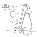
Fig. 2 is a view showing a configuration example of a blast furnace system to which the blow pipe structure shown in Fig. 1 is applied.
BEST MODE FOR CARRYING OUT THE INVENTION Hereinafter, an embodiment of a blow pipe structure according to the present invention will be described with reference to the drawings.
The blow pipe structure of the present embodiment is used in a blast furnace facility in which raw coal is blown into the blast furnace from the tweeter with low-grade coal.
2, the raw material 1 such as iron ore, limestone, and coal is supplied from the raw material
A pulverized
The modified pulverized coal (reformed coal) 3 produced by the pulverized
The pulverized
The preferable configuration of the pulverized
Although the pulverized coal (3) is largely reduced by the removal of the tar generator of the oxygen-containing functional groups (carboxyl group, aldehyde group, ester group and hydroxyl group), decomposition (reduction) of the main skeleton (combustion components centering on C, H and O) ) Is greatly suppressed. Therefore, when the
In order to manufacture (modify) the pulverized
After the moisture is removed in the above-described drying step, a carbonization step (460 to 590 ° C (preferably 500 to 550 ° C) for 0.5 to 1 hour) is performed again in the coking oven in a low oxygen atmosphere (oxygen concentration: . By this carburizing process, the raw fuel is dry-distilled, whereby the generated water, carbon dioxide and the tar are removed as the dry gas or the dry-gas oil.
Thereafter, the raw cigarette which has been subjected to the cooling step is easily pulverized (particle diameter: 77 μm or less (80% pass)) in the pulverization step after cooling (50 ° C. or less) in an oxygen- .
In the present embodiment, for example, as shown in Fig. 1, a pulverized
That is, the
More specifically, the
The
In other words, the
The
The
In the
As a result, compared with the conventional structure in which the
In the blow pipe structure of the present embodiment described above, the flow path resistance is reduced in the outer
As a result, the
The
The blow pipe structure described above preferably includes a
Therefore, when nitrogen is blown into the
The blow pipe structure described above preferably includes an
Therefore,
Here, the oxygen concentration adjustment of the
For example, the
As a result, the burning rate of the pulverized
In addition to the adjustment of the oxygen concentration, addition of nitrogen into the
According to the blow pipe structure of the present embodiment described above, the inner and
Therefore, even if the softening point of the pulverized
The component contained in the slag of the above-described
The present invention is not limited to the above-described embodiments, and can be appropriately changed within the scope not departing from the gist of the present invention.
1 raw material
2 hot winds
3 Pulverized coal (reformed coal)
4 Carrier gas
5 Pig iron (chartered)
10 Raw material dosing device
20 Blast furnace body
21 open hopper
22 Twi
30 blow pipe
30a Appearance
30b inner pipe
30c inner pipe outlet
30d Outer channel
31 Injection Lance (Lance)
31a powder discharge
40 hot air feeder
41 canal
50 Pulverized coal production equipment
60 Cyclone Separator
70 Storage tank
80 Euro Resistance
81 slope
90 Nitrogen inlet tube
91 Oxygen inlet pipe
Claims (4)
And an inner pipe which is continuously opened from the capillary tube to the vicinity of the tweeter is provided inside the outer tube continuous from the capillary tube for supplying the hot air to the twister, And a blow pipe structure opened inside the inner pipe.
Wherein a flow path resistance is provided in a flow path formed between the outer tube and the inner tube and at a position near the outlet of the inner tube.
And a nitrogen inlet pipe for supplying nitrogen to the inner pipe.
And an oxygen inlet pipe for supplying oxygen to the outer pipe.
Applications Claiming Priority (3)
| Application Number | Priority Date | Filing Date | Title |
|---|---|---|---|
| JP2012207273A JP6012359B2 (en) | 2012-09-20 | 2012-09-20 | Blow pipe structure |
| JPJP-P-2012-207273 | 2012-09-20 | ||
| PCT/JP2013/074402 WO2014045945A1 (en) | 2012-09-20 | 2013-09-10 | Blow-pipe structure |
Publications (1)
| Publication Number | Publication Date |
|---|---|
| KR20150040363A true KR20150040363A (en) | 2015-04-14 |
Family
ID=50341259
Family Applications (1)
| Application Number | Title | Priority Date | Filing Date |
|---|---|---|---|
| KR20157006492A KR20150040363A (en) | 2012-09-20 | 2013-09-10 | Blow-pipe structure |
Country Status (7)
| Country | Link |
|---|---|
| US (1) | US20150275322A1 (en) |
| JP (1) | JP6012359B2 (en) |
| KR (1) | KR20150040363A (en) |
| CN (1) | CN104603296A (en) |
| DE (1) | DE112013004592T5 (en) |
| IN (1) | IN2015DN02018A (en) |
| WO (1) | WO2014045945A1 (en) |
Families Citing this family (2)
| Publication number | Priority date | Publication date | Assignee | Title |
|---|---|---|---|---|
| JP6057642B2 (en) * | 2012-09-20 | 2017-01-11 | 三菱重工業株式会社 | Slag removing device and slag removing method |
| KR102348088B1 (en) * | 2017-01-02 | 2022-01-10 | 삼성전자주식회사 | Clothing drying apparatus |
Family Cites Families (6)
| Publication number | Priority date | Publication date | Assignee | Title |
|---|---|---|---|---|
| JP2761885B2 (en) * | 1988-04-21 | 1998-06-04 | 日本鋼管株式会社 | Pulverized coal burner |
| KR970009084B1 (en) * | 1994-12-29 | 1997-06-05 | 김만제 | Apparatus for melting fine coals and method of melting the same using the apparatus |
| JP2000265205A (en) * | 1999-03-15 | 2000-09-26 | Nippon Steel Corp | Blasting tuyere |
| WO2007130362A2 (en) * | 2006-05-01 | 2007-11-15 | Sierra Energy | Tuyere for oxygen blast furnance/converter system |
| CN102312029A (en) * | 2011-01-24 | 2012-01-11 | 张昭贵 | Air supplying device of blast furnace as well as combustion method and oxygen-enriching method of injected coal powder thereof |
| JP5775476B2 (en) * | 2012-03-06 | 2015-09-09 | 新日鐵住金株式会社 | Reducing gas blowing method and blowing lance from blast furnace tuyere |
-
2012
- 2012-09-20 JP JP2012207273A patent/JP6012359B2/en not_active Expired - Fee Related
-
2013
- 2013-09-10 IN IN2018DEN2015 patent/IN2015DN02018A/en unknown
- 2013-09-10 DE DE112013004592.3T patent/DE112013004592T5/en not_active Withdrawn
- 2013-09-10 KR KR20157006492A patent/KR20150040363A/en not_active Application Discontinuation
- 2013-09-10 US US14/428,553 patent/US20150275322A1/en not_active Abandoned
- 2013-09-10 CN CN201380045513.8A patent/CN104603296A/en active Pending
- 2013-09-10 WO PCT/JP2013/074402 patent/WO2014045945A1/en active Application Filing
Also Published As
| Publication number | Publication date |
|---|---|
| WO2014045945A1 (en) | 2014-03-27 |
| CN104603296A (en) | 2015-05-06 |
| US20150275322A1 (en) | 2015-10-01 |
| JP6012359B2 (en) | 2016-10-25 |
| JP2014062291A (en) | 2014-04-10 |
| DE112013004592T5 (en) | 2015-06-11 |
| IN2015DN02018A (en) | 2015-08-14 |
Similar Documents
| Publication | Publication Date | Title |
|---|---|---|
| KR101648323B1 (en) | Blow-pipe structure | |
| JP5923968B2 (en) | Blast furnace operation method | |
| JP5574708B2 (en) | Mineral fiber manufacturing method and manufacturing apparatus | |
| KR20120023057A (en) | Blast furnace operation method | |
| JP5470251B2 (en) | Feather for producing molten iron and gas injection method using the same | |
| KR20150040363A (en) | Blow-pipe structure | |
| WO2014045949A1 (en) | Slag removal device and slag removal method | |
| JP2015509034A (en) | Reusing materials when making mineral melts | |
| JP2009014331A (en) | Burner lance for charging powdery and granular matter of smelting reduction furnace and manufacturing method of molten metal by smelting reduction | |
| KR101629123B1 (en) | Blast furnace operation method | |
| JP4894949B2 (en) | Blast furnace operation method | |
| JP2010156025A (en) | Burner lance for charging powdery and granular material into smelting reduction furnace, and method for producing molten metal by smelting reduction | |
| CN103189320A (en) | An apparatus and method for making a mineral melt | |
| KR101648683B1 (en) | Method for producing pig iron, and blast furnace to be used therefor | |
| JP2013028832A (en) | Molten iron refining method | |
| JP5831694B2 (en) | Sintering machine | |
| JP2013221159A (en) | Method of refining molten iron | |
| KR100742603B1 (en) | Tar coated fine ore for solution carbon fines around raceway in blast furnace and its fabrication method | |
| AU2012355193B2 (en) | Blast furnace operation method | |
| KR101693136B1 (en) | Blast furnace operation method | |
| EP1154825B1 (en) | Method for optimising the operation of a blast furnace | |
| JPS58204110A (en) | Vertical type furnace for production of molten metal | |
| KR20130026129A (en) | Apparatus for supplying pulverized coal to blast furnace | |
| JPH08302411A (en) | Method for melting scrap |
Legal Events
| Date | Code | Title | Description |
|---|---|---|---|
| A201 | Request for examination | ||
| E902 | Notification of reason for refusal | ||
| E601 | Decision to refuse application |