KR20150036324A - Heatable fluid bag - Google Patents
Heatable fluid bag Download PDFInfo
- Publication number
- KR20150036324A KR20150036324A KR1020157002730A KR20157002730A KR20150036324A KR 20150036324 A KR20150036324 A KR 20150036324A KR 1020157002730 A KR1020157002730 A KR 1020157002730A KR 20157002730 A KR20157002730 A KR 20157002730A KR 20150036324 A KR20150036324 A KR 20150036324A
- Authority
- KR
- South Korea
- Prior art keywords
- bag
- insulating layer
- end support
- support member
- housing
- Prior art date
Links
Images


Classifications
-
- H—ELECTRICITY
- H05—ELECTRIC TECHNIQUES NOT OTHERWISE PROVIDED FOR
- H05B—ELECTRIC HEATING; ELECTRIC LIGHT SOURCES NOT OTHERWISE PROVIDED FOR; CIRCUIT ARRANGEMENTS FOR ELECTRIC LIGHT SOURCES, IN GENERAL
- H05B3/00—Ohmic-resistance heating
- H05B3/20—Heating elements having extended surface area substantially in a two-dimensional plane, e.g. plate-heater
- H05B3/34—Heating elements having extended surface area substantially in a two-dimensional plane, e.g. plate-heater flexible, e.g. heating nets or webs
-
- A—HUMAN NECESSITIES
- A47—FURNITURE; DOMESTIC ARTICLES OR APPLIANCES; COFFEE MILLS; SPICE MILLS; SUCTION CLEANERS IN GENERAL
- A47J—KITCHEN EQUIPMENT; COFFEE MILLS; SPICE MILLS; APPARATUS FOR MAKING BEVERAGES
- A47J41/00—Thermally-insulated vessels, e.g. flasks, jugs, jars
- A47J41/0038—Thermally-insulated vessels, e.g. flasks, jugs, jars comprising additional heating or cooling means, i.e. use of thermal energy in addition to stored material
- A47J41/005—Thermally-insulated vessels, e.g. flasks, jugs, jars comprising additional heating or cooling means, i.e. use of thermal energy in addition to stored material comprising heat or cold producing means, i.e. energy transfer from outside the vessel
-
- H—ELECTRICITY
- H05—ELECTRIC TECHNIQUES NOT OTHERWISE PROVIDED FOR
- H05B—ELECTRIC HEATING; ELECTRIC LIGHT SOURCES NOT OTHERWISE PROVIDED FOR; CIRCUIT ARRANGEMENTS FOR ELECTRIC LIGHT SOURCES, IN GENERAL
- H05B3/00—Ohmic-resistance heating
- H05B3/20—Heating elements having extended surface area substantially in a two-dimensional plane, e.g. plate-heater
- H05B3/22—Heating elements having extended surface area substantially in a two-dimensional plane, e.g. plate-heater non-flexible
- H05B3/28—Heating elements having extended surface area substantially in a two-dimensional plane, e.g. plate-heater non-flexible heating conductor embedded in insulating material
-
- H—ELECTRICITY
- H05—ELECTRIC TECHNIQUES NOT OTHERWISE PROVIDED FOR
- H05B—ELECTRIC HEATING; ELECTRIC LIGHT SOURCES NOT OTHERWISE PROVIDED FOR; CIRCUIT ARRANGEMENTS FOR ELECTRIC LIGHT SOURCES, IN GENERAL
- H05B3/00—Ohmic-resistance heating
- H05B3/40—Heating elements having the shape of rods or tubes
- H05B3/42—Heating elements having the shape of rods or tubes non-flexible
- H05B3/48—Heating elements having the shape of rods or tubes non-flexible heating conductor embedded in insulating material
-
- H—ELECTRICITY
- H05—ELECTRIC TECHNIQUES NOT OTHERWISE PROVIDED FOR
- H05B—ELECTRIC HEATING; ELECTRIC LIGHT SOURCES NOT OTHERWISE PROVIDED FOR; CIRCUIT ARRANGEMENTS FOR ELECTRIC LIGHT SOURCES, IN GENERAL
- H05B3/00—Ohmic-resistance heating
- H05B3/78—Heating arrangements specially adapted for immersion heating
- H05B3/80—Portable immersion heaters
-
- H—ELECTRICITY
- H05—ELECTRIC TECHNIQUES NOT OTHERWISE PROVIDED FOR
- H05B—ELECTRIC HEATING; ELECTRIC LIGHT SOURCES NOT OTHERWISE PROVIDED FOR; CIRCUIT ARRANGEMENTS FOR ELECTRIC LIGHT SOURCES, IN GENERAL
- H05B2203/00—Aspects relating to Ohmic resistive heating covered by group H05B3/00
- H05B2203/021—Heaters specially adapted for heating liquids
-
- H—ELECTRICITY
- H05—ELECTRIC TECHNIQUES NOT OTHERWISE PROVIDED FOR
- H05B—ELECTRIC HEATING; ELECTRIC LIGHT SOURCES NOT OTHERWISE PROVIDED FOR; CIRCUIT ARRANGEMENTS FOR ELECTRIC LIGHT SOURCES, IN GENERAL
- H05B2203/00—Aspects relating to Ohmic resistive heating covered by group H05B3/00
- H05B2203/022—Heaters specially adapted for heating gaseous material
Abstract
가열가능한 유체 충전된 백을 위한 가열기 요소는 전력원에 접속되었을 때 가열기 요소가 가열되는 것을 허용하기 위한 전력 접속 부재 수단을 갖는 발열 부재를 포함한다. 이 요소는 또한 단부를 갖는 제 1 절연층 및 단부를 갖는 제 1 열전도층을 포함한다. 발열 부재는 제 1 절연층으로 피복되고, 다음에 제 1 절연층은 제 1 열전도층에 의해 피복되고, 이들의 단부는 내측의 단부 지지부재에 의해 결합된다. 전력 접속 부재 수단이 관통하는 것을 허용하기 위한 적어도 하나의 개구를 구비하는 적어도 하나 내측의 단부 지지부재를 구비하는 내측의 단부 지지부재는 절연성이다.The heater element for the heatable fluid-filled bag includes a heating element having power connection member means for allowing the heater element to be heated when connected to a power source. The element also includes a first thermally conductive layer having an end and a first insulating layer having an end. The heating member is covered with the first insulating layer, and then the first insulating layer is covered with the first heat conductive layer, and these ends are joined by the inner end supporting member. The inner end support member having at least one inner end support member having at least one opening for allowing the power connection member means to penetrate is insulating.
Description
본 발명은 가열 또는 냉각될 수 있는 백 또는 파우치 내에 수용된 유체를 포함하는 유체 백에 관한 것이다. 본 발명은 특히 휴대형 유체 백을 위한 가열기를 대상으로 하지만, 이것에 한정되지 않는다.The present invention relates to a fluid bag comprising a fluid received in a bag or pouch that can be heated or cooled. The present invention is particularly directed to a heater for a portable fluid bag, but is not limited thereto.
온수용 물병은 수년에 걸쳐 공지되어 왔다. 이것은 비록 저렴하지만, 충전하기가 어렵고, 가열은 오래 지속되지 못한다. 온수를 따를 때 사용자가 데이거나 화상을 입는 사고가 많이 발생한다. 또한 이러한 온수용 물병은 고령자 또는 어린이가 사용하기에 매우 어려울 수 있는 나사식 마개를 가지고 있다. 이러한 유형의 병은 열을 그리 오랫동안 유지하지 못한다는 것이 주지되어 있다.Water bottles have been known for many years. This is inexpensive, but difficult to charge, and does not last long. When you follow hot water, many accidents happen when you are dying or burning. Also, these water bottles have screw caps that can be very difficult for the elderly or children to use. It is well known that this type of disease does not retain heat for too long.
주전자에서 사용되는 것과 같은 단순 전극은 연소 또는 전기 쇼크의 위험이 매우 높으므로 전기적으로 하전될 수 있거나 및/또는 신체에 닿을 수 있거나 또는 접촉될 수 있는 임의의 기구에서는 사용될 수 없다.Simple electrodes, such as those used in kettles, can not be used in any device that can be electrically charged and / or contacted or contacted because of the high risk of burning or electrical shock.
본 명세서에서 반대의 뜻이 명시적으로 언급되지 않는 한 지식의 문헌, 행위 또는 요소가 언급되거나 검토되는 경우, 이러한 참조 또는 검토는 지식의 문헌, 행위 또는 요소 또는 이들의 임의의 조합이 우선일에 공연히 입수가능하다거나, 대중에 공지되었다거나, 상식의 일부라거나, 또는 본 명세서가 고려하는 임의의 문제를 해결하기 위한 시도와 관련되어 공지된 것이라는 것을 인정하는 것은 아니다.In the absence of any express reference to the contrary in this specification, where a document, act or element of knowledge is referred to or reviewed, such reference or review shall be based on the document, act or element of knowledge, or any combination thereof, Nor is it acknowledged to be publicly known, publicly known, part of common sense, or otherwise known to be associated with an attempt to solve any problems which the present specification contemplates.
본 발명의 목적은 공지된 기술의 단점 및 한계의 일부를 개선하거나 적어도 대중에게 유용한 선택을 제공하는 개선된 가열가능한 또는 냉각가능한 유체 백 및 유체 가열기를 제공하는 것이다.It is an object of the present invention to provide an improved heatable or coolable fluid bag and fluid heater which improves some of the disadvantages and limitations of the known art or at least provides a useful choice to the public.
제 1 양태에서, 광범위하게 말하면 본 발명은 내부에 유체를 수용하기 위한 포위된 공간을 제공하도록 적합되는 측면을 갖는 백을 포함하는 가열가능한 유체 백에 있는 것으로서, 상기 백은 다음의 적어도 하나의 가열 요소, 전력 접속 수단, 회로 및 스위칭 수단인 적어도 하나의 기계적 스위치의 부품을 포함하고, 이것에 의해 상기 부품은, 전력 접속 수단이 전력원에 접속되었을 때, 유체의 가열을 위해 가열 요소의 가열이 유발되도록 백의 내측에서 함께 전기적으로 접속되도록 배치되고, 상기 자기 스위치는 기체 또는 압력의 축적을 방지하여 폭발을 예방하도록 적합되고, 상기 자기 스위치는 단부를 갖는 세장형 부재를 포함하고, 세장형 부재의 일단부는 백의 내측의 일측에 위치되는 회로에 연결되고, 타단부는 백의 타측의 내측에 연결되고, 이것에 의해 상기 회로는 백이 백의 측면들 사이의 특정의 거리를 초과하여 팽창하는 경우에 차단될 수 있고, 이것에 의해 백이 가열 요소에 의해 특정 온도까지 가열된 후에, 백은 이 백을 휴대형 가열 부재로서 사용할 수 있도록 전력원으로부터 차단될 수 있다.In a first aspect, broadly speaking, the present invention is a heatable fluid bag comprising a bag having a side adapted to provide an enclosed space for receiving fluid therein, said bag comprising at least one of the following: Wherein the heating element is heated to heat the fluid when the power connection means is connected to the power source, wherein the heating element is connected to the at least one mechanical switch, Said magnetic switch being adapted to prevent accumulation of gas or pressure to prevent explosion, said magnetic switch comprising a elongate member having an end, said elongate member One end is connected to a circuit located on one side of the inside of the bag and the other end is connected to the inside of the other side of the bag, The circuit can be shut off when the bag expands beyond a certain distance between the sides of the bag so that the bag is heated to a certain temperature by the heating element, It can be disconnected from the power source for use.
바람직하게, 전력 접속 수단은 전력원의 플러그를 위한 소켓을 포함하는 하우징의 일부로서 형성되고, 여기서 하우징은 백의 내측에 연결되지만, 수용된 유체로부터 전기적으로 및 유체적으로 분리된다.Preferably, the power connection means is formed as part of a housing including a socket for a plug of a power source, wherein the housing is connected to the inside of the bag but is electrically and fluidly separated from the received fluid.
바람직하게, 백은 10 분 내에 가열될 수 있고, 전력원으로부터 분리되었을 때 백의 가열은 5 시간 동안 지속될 수 있다. Preferably, the bag can be heated within 10 minutes and heating of the bag can be continued for 5 hours when separated from the power source.
바람직하게, 세장형 부재의 일단부는 백의 내측에 용접된다.Preferably, one end of the elongate member is welded to the inside of the bag.
바람직하게, 하우징은 적어도 하나 블리드 밸브를 포함하고, 상기 블리드 밸브는 스위치를 포함하는 하우징 내에 위치되는 적어도 하나 변형가능한 개구를 포함하고, 상기 스위치는 백 내의 과잉 압력을 제거하도록 적합되고, 상기 개구는 백 내의 유체 또는 포위된 공간에 연결된다. 바람직하게, 모든 전기 회로, 커넥터, 배선 및 스위칭 부품을 위해 이중 절연이 제공된다.Preferably, the housing comprises at least one bleed valve, wherein the bleed valve comprises at least one deformable opening located in a housing comprising a switch, the switch being adapted to remove excess pressure in the bag, To the fluid in the bag or to the enclosed space. Preferably, double insulation is provided for all electrical circuits, connectors, wiring and switching components.
바람직하게, 백은 용접된 이음매를 구비하는 적어도 하나의 층의 PVC로 형성되는 재료를 갖는 재료로 형성되고, 하우징은 온도 제어를 위해 적어도 하나의 온도자동조절기를 포함한다. 바람직하게, 가열기 요소는 열적 링크 퓨즈(link fuse)를 포함하는 가열기 케이지에 수용되는 전열선을 포함하고, 여기서 가열기 케이지는 포위된 공간 내에서 백에 부착되지만 전열선은 그것으로부터 전기적으로 및 유체적으로 분리된다.Preferably, the bag is formed of a material having a material formed of at least one layer of PVC with a welded joint, and the housing comprises at least one temperature regulator for temperature control. Preferably, the heater element comprises a heating wire received in a heater cage including a thermal link fuse, wherein the heater cage is attached to the bag in an enclosed space, wherein the heating wire is electrically and fluidly do.
바람직하게, 가열기 케이지는 내부에 수용되는 이중 절연된 전열선을 구비하는 상하측 케이싱 부재(51, 63)를 포함하고, 여기서 이중 절연은 교호 순서의 절연 시트와 전도성 시트를 포함하고, 이것에 의해 절연 시트는 마이카 재료를 포함하고, 전도성 시트는 알루미늄을 포함한다. Preferably, the heater cage includes upper and lower casing members (51, 63) having double insulated heating wires housed therein, wherein the double insulation comprises an insulating sheet and a conductive sheet in alternating order, The sheet comprises a mica material, and the conductive sheet comprises aluminum.
바람직하게, 절연성 시트 및 전도성 시트의 순서는 제 1 외부 전도성 시트(52)(외부 알루미늄 셸), 제 1 외부 절연 시트(53)(마이카 시트), 제 1 내부 전도성 시트(54)(내부 알루미늄 시트), 제 1 내부 절연 시트(55)(마이카 시트), 중간 외부 외주 링(56)(플라스틱 링), 전열선(57)을 위한 마이카 지지 골격 부재, 전열선(58), 제 2 내부 절연 시트(59)(마이카 시트), 제 2 전도성 시트(60)(알루미늄 시트), 제 2 외부 절연 시트(61)(마이카 시트), 제 2 외부 전도성 시트(62)(알루미늄 시트)를 포함할 수 있다. 바람직하게, 가열기 요소는 U자형 또는 평면형일 수 있고, 유체는 가열되거나 또는 냉각될 수 있는 임의의 유체일 수 있다.Preferably, the order of the insulating sheet and the conductive sheet is selected from the group consisting of a first outer conductive sheet 52 (outer aluminum shell), a first outer insulating sheet 53 (mica sheet), a first inner conductive sheet 54 ), A first inner insulating sheet 55 (mica sheet), a middle outer outer peripheral ring 56 (plastic ring), a mica supporting skeletal member for the
바람직하게, 상기 하우징은 접지 접속을 검증할 수 있는 적어도 하나의 접지 시험점을 포함하고, 하우징은 전력이 회로에 접속된 것을 확인하기 위해 전력 접속에 전기적으로 접속된 표시등을 포함한다. 바람직하게, 백의 포위된 공간으로부터 공기나 기체를 배출시킬 수 있도록 블리드 밸브의 개구 내에 삽입할 수 있도록 하우징 내에서 리세스 내에 제거가능한 프로브가 설치된다.Preferably, the housing includes at least one ground test point capable of verifying a ground connection, and the housing includes an indicator light electrically connected to the power connection to confirm that power is connected to the circuit. Preferably, a removable probe is provided in the recess in the housing so that it can be inserted into the opening of the bleed valve to allow air or gas to escape from the enclosed space of the bag.
제 2 양태에서, 광범위하게 말하면, 본 발명은 가열기 케이지 내에 수용되는 전열선을 포함하는 가열기 요소에 있는 것으로서, 여기서 가열기 케이지는 유체를 수용하는 백의 내측에 부착될 수 있고, 전열선은 이것으로부터 전기적으로 및 유체적으로 분리되고, 그리고 유체를 가열하기 위해 전선이 가열되도록 전력원에 접속될 수 있고, 가열기 케이지는 상부 및 하부 케이싱 부재(51, 63)를 포함하고, 여기서 교호 순서의 절연 시트 및 전도성 시트가 상부 및 하부 케이싱 부재 사이에 위치되고, 여기서 절연성 시트 및 전도성 시트의 순서는 제 1 외부 전도성 시트(52)(외부 알루미늄 셸), 제 1 외부 절연 시트(53)(마이카 시트), 제 1 내부 전도성 시트(54)(내부 알루미늄 시트), 제 1 내부 절연 시트(55)(마이카 시트), 중간 외부 외주 링(56)(플라스틱 링), 전열선(57)을 위한 마이카 지지 골격 시트 부재, 전열선(58), 제 2 내부 절연 시트(59)(마이카 시트), 제 2 전도성 시트(60)(알루미늄 시트), 제 2 외부 절연 시트(61)(마이카 시트), 제 2 외부 전도성 시트(62)(알루미늄 시트)를 포함할 수 있고, 이것에 의해 외부 케이싱 부재가 결합된다.In a second aspect, broadly speaking, the present invention resides in a heater element comprising a heating element accommodated in a heater cage, wherein the heater cage can be attached to the interior of the bag housing the fluid, And the heater cage includes upper and lower casing members (51, 63), wherein an alternating sequence of the insulating sheet and the conductive sheet Wherein the order of the insulating sheet and the conductive sheet is selected from the group consisting of a first outer conductive sheet 52 (outer aluminum shell), a first outer insulating sheet 53 (mica sheet) A conductive outer sheet 54 (inner aluminum sheet), a first inner insulating sheet 55 (mica sheet), a middle outer outer ring 56 (plastic ring) A second inner insulating sheet 59 (a mica sheet), a second conductive sheet 60 (an aluminum sheet), a second outer insulating sheet 61 (a mica sheet) And a second outer conductive sheet 62 (aluminum sheet), whereby the outer casing member is engaged.
바람직하게, 가열기 요소는 가열기 선이 과열되는 경우 안전 메커니즘으로서 작용하기 위해 특정 온도에 설정되는 전열선에 전기적 결합된 열 퓨즈를 포함하고, 가열기 요소는 U자형 또는 평면형일 수 있고, 절연 시트는 마이카 재료를 포함하고, 전도성 시트는 알루미늄 재료를 포함한다. Preferably, the heater element includes a thermal fuse electrically coupled to a heating element set at a specific temperature to act as a safety mechanism when the heater element is overheated, the heater element may be U-shaped or planar, And the conductive sheet includes an aluminum material.
제 3 양태에서, 본 발명은 유체를 수용하기 위한 포위된 공간을 제공하도록 적합된 측면을 갖는 백 및 자기 스위치를 포함하는 냉각 유체 백을 포함하고, 이것에 의해 유체는 냉동되도록 적합되고, 여기서 자기 스위치는 기체 압력의 축적을 방지하여 폭발을 예방하도록 적합되고, 그리고 단부들을 갖는 세장형 부재를 포함하고, 일단부는 백의 내측의 일측에 위치되는 회로에 연결되고, 타단부는 백의 타측의 내측에 연결되고, 이것에 의해 회로는 백이 이 백의 측면들 사이의 특정의 거리를 초과하여 팽창하는 경우에 차단될 수 있고, 여기서 유체는 부동제(antifreeze)이다. 바람직하게, 하우징은 적어도 하나 블리드 밸브를 포함하고, 상기 블리드 밸브는 스위치를 포함하는 하우징 내에 위치되는 적어도 하나 변형가능한 개구를 포함하고, 상기 스위치는 백 내의 과잉 압력을 제거하도록 적합된다.In a third aspect, the invention includes a cooling fluid bag comprising a bag and a magnetic switch having a side adapted to provide an enclosed space for receiving fluid, whereby the fluid is adapted to be frozen, The switch is adapted to prevent accumulation of gas pressure to prevent explosion and includes a elongate member having ends, one end connected to a circuit located on one side of the inside of the bag and the other end connected to the inside of the other side of the bag Whereby the circuit can be shut off when the bag expands beyond a certain distance between the sides of the bag, wherein the fluid is antifreeze. Preferably, the housing comprises at least one bleed valve, said bleed valve comprising at least one deformable opening located in a housing comprising a switch, said switch adapted to remove excess pressure in the bag.
제 4 양태에서, 본 발명은 가열가능한 유체 충전된 백을 위한 가열기 요소로서, 상기 요소는 전력원에 연결되었을 때 가열기 요소가 가열되도록 허용하기 위한 전력 접속 부재 수단을 갖는 발열 부재, 단부를 갖는 제 1 절연층, 및 단부를 갖는 제 1 열전도층을 포함하고, 이것에 의해 상기 발열 부재는 상기 제 1 절연층에 의해 피복되고, 다음에 상기 제 1 절연층을 피복하기 위해 상기 제 1 열전도층이 배치되고, 상기 제 1 절연층과 상기 제 1 열전도층의 단부는 내측의 단부 지지부재에 의해 결합되고, 상기 내측의 단부 지지부재는 상기 전력 접속 부재 수단의 통과를 허용하는 적어도 하나의 개구를 구비하는 적어도 하나의 내측의 단부 지지부재를 갖는 절연성인, 가열가능한 유체 충전된 백을 위한 가열기 요소를 포함한다.In a fourth aspect, the present invention provides a heater element for a heatable fluid-filled bag, the element comprising a heating element having power connection member means for allowing the heater element to be heated when connected to a power source, And a first thermally conductive layer having one end and an insulating layer, wherein the heat generating member is covered by the first insulating layer, and the first thermally conductive layer is formed to cover the first insulating layer. And the end of the first insulating layer and the first thermally conductive layer are joined by an inner end support member and the inner end support member has at least one opening allowing the passage of the power connection member means And a heater element for the heatable fluidly-packed bag, wherein the heater element has at least one inner end support member.
바람직하게, 상기 전력 접속 부재 수단은 전극 플레이트 부재들 사이에 상기 발열 부재를 개재하는 상기 발열 부재에 전기적으로 접속되는 상기 전극 플레이트 부재의 형태로 적어도 하나의 전극을 포함하고, 상기 전력 접속 부재 수단은 상기 가열기 요소와 상기 전력 접속 수단 사이의 전력 접속을 허용하도록 각각의 전극 플레이트 부재에 전기적으로 접속되는 적어도 하나의 전선을 포함한다.Preferably, the power connection member means includes at least one electrode in the form of the electrode plate member electrically connected to the heating member through the heating member, between the electrode plate members, and the power connection member means And at least one electrical wire electrically connected to each electrode plate member to allow a power connection between the heater element and the power connection means.
바람직하게, 상기 가열기 요소는 단부를 갖는 제 2 절연층, 단부를 갖는 제 2 열전도층 및 중간의 단부 지지부재를 포함하고, 상기 제 2 절연층은 상기 제 1 열전도층을 피복하고, 슬리브의 형태이고, 다음에 상기 제 2 절연층을 피복하는 슬리브 형상의 상기 제 2 절연층이 배치되고, 이것에 의해 상기 중간의 단부 지지부재는 절연재로 형성되고, 상기 내측의 단부 지지부재를 차폐하도록, 그리고 상기 내측의 단부 지지부재와 접촉하도록 상기 제 2 절연 부재 및 제 2 열전도 부재의 단부 내에 슬라이딩 가능하게 끼워맞춤되도록 적합되고, 적어도 하나의 중간의 단부 지지부재는 상기 전력 접속 부재 수단의 통과를 허용하기 위한 적어도 하나의 개구를 갖는다.Preferably, the heater element includes a second insulating layer having an end, a second thermally conductive layer having an end, and an intermediate end support member, the second insulating layer covering the first thermally conductive layer, And the second insulating layer in the form of a sleeve covering the second insulating layer is disposed so that the intermediate end supporting member is formed of an insulating material and shields the inside end supporting member, And the at least one intermediate end support member is adapted to be slidably fitted in the end portions of the second insulating member and the second heat conductive member so as to come into contact with the inner end support member, At least one opening.
바람직하게, 상기 발열 부재는 정의 온도 계수(PTC)로 형성되고, 상기 제 1 절연층 및 제 2 절연층은 플라스틱으로 형성되고, 상기 제 1 열전도층 및 제 2 열전도층은 슬리브의 형상의 금속으로 형성되고, 상기 내측의 단부 지지부재 및 중간의 단부 지지부재는 돌출하는 오목한 립 부분을 구비하는 내측을 구비하는 플레이트 캡 형상의 부재로서 형성되고, 상기 개구는 상기 립 부분의 것에 대해 상기 플레이트 캡의 대향측 상의 돌출하는 원통형 부재로서 형성된다.Preferably, the heating member is formed of a positive temperature coefficient (PTC), the first insulating layer and the second insulating layer are made of plastic, and the first and second thermally conductive layers are made of a metal in the form of a sleeve Wherein the inner end support member and the intermediate end support member are formed as a plate cap-shaped member having an inner side having a projecting concave lip portion, the opening being defined by a portion of the plate cap And is formed as a cylindrical member protruding on the opposite side.
바람직하게, 상기 외측의 단부 지지부재는 상기 제 2 열전도층의 각각의 단부 상에 상기 중간의 단부 지지부재를 접촉시키고, 이것에 의해 적어도 하나의 외측의 단부 지지부재는 유체를 배제하도록 실링될 수 있는 상기 전기 접속용 개구를 갖고, 상기 내측, 중간 및 외측의 단부 지지부재의 개구는 모든 개구를 통한 전기 접속을 허용하도록 정렬되고, 각각의 외측의 단부 지지부재는 상기 백의 내측에 연결할 수 있도록, 그리고 상기 제 2 열전도 부재의 단부에 고정되도록 적합된 푸트(foot)를 구비한 L자형이다.Preferably, the outer end support member contacts the intermediate end support member on each end of the second thermally conductive layer, whereby at least one outer end support member can be sealed to exclude fluid Wherein the openings of the inner, intermediate, and outer end support members are aligned to allow electrical connection through all of the openings, each of the outer end support members being connectable to the inside of the bag, And an L-shaped portion having a foot adapted to be fixed to the end portion of the second heat conductive member.
바람직하게, 제 1 및 제 2 절연층은 각각 적어도 이중의 절연층으로서 형성될 수 있다. Preferably, the first and second insulating layers may each be formed as at least a double insulating layer.
제 5 양태에서, 본 발명은 전력원에 전기적으로 접속되도록 적합된 가열가능한 유체 충전된 백으로서, 상기 유체 충전된 백은 유체를 수용하는 백, 적어도 하나 가열기 요소, 및 상기 백이 상기 전력원에 전기적으로 연결되는 것을 허용하도록 적합된 전력 접속 수단을 포함하는 하우징을 포함하고, 상기 하우징은 적어도 하나의 절연층으로 이루어지고, 상기 가열기 요소는 전력 접속 부재 수단을 갖는 발열 수단, 단부를 갖는 제 1 절연층, 및 단부를 갖는 제 1 열전도층을 포함하고, 상기 발열 부재는 상기 제 1 절연층에 의해 피복되고, 다음에 상기 제 1 절연층을 피복하는 상기 열전도층이 배치되고, 상기 제 1 제 2 절연층과 열 전도층의 단부는 내측의 단부 지지부재에 의해 결합되고, 상기 내측의 단부 지지부재는 절연성이거나 절연성 재료로 형성되고, 상기 전력 접속 수단에 접속하기 위해 상기 전력 접속 부재 수단의 통과를 허용하는 적어도 하나의 개구를 구비하는 적어도 하나의 내측의 단부 지지부재를 갖는, 전력원에 전기적으로 접속되도록 적합된 가열가능한 유체 충전된 백을 포함한다. In a fifth aspect, the invention is a heatable fluidly-filled bag adapted to be electrically connected to a power source, the fluidly-filled bag comprising a bag for receiving a fluid, at least one heater element, Wherein the housing comprises at least one insulating layer, the heater element comprising: a heating means having power connection member means; a first insulation with end portions; And a first thermally conductive layer having a first end, a first end, a second end, a first end, a second end, and a first end, The end portions of the insulating layer and the heat conduction layer are joined by an inner end supporting member, and the inner end supporting member is formed of an insulating or insulating material, And at least one inner end support member having at least one opening to permit passage of the power connection member means for connection to the power connection means, Bag.
바람직하게, 상기 가열기 요소는 단부를 갖는 제 2 절연층, 단부를 갖는 제 2 열전도층 및 중간의 단부 지지부재를 포함하고, 상기 제 2 절연층은 상기 제 1 열전도층을 피복하고, 슬리브의 형상이고, 다음에 상기 제 2 절연층을 피복하는 슬리브로서 형성되는 상기 제 2 절연층이 배치되고, 이것에 의해 상기 중간의 단부 지지부재는 절연재로 형성되고, 상기 내측의 단부 지지부재를 차폐하도록, 그리고 상기 내측의 단부 지지부재와 접촉하도록 상기 제 2 절연 부재 및 상기 제 2 열전도 부재의 단부 내에 슬라이딩 가능하게 끼워맞춤되도록 적합되고, 적어도 하나의 중간의 단부 지지부재는 상기 전력 접속 부재 수단의 통과를 허용하는 적어도 하나의 개구를 갖고, 외측의 단부 지지부재는 상기 제 2 열전도층의 각각의 단부 상에 상기 중간의 단부 지지부재를 접촉시키고, 이것에 의해 적어도 하나의 상기 외측의 단부 지지부재는 유체를 배제하도록 실링될 수 있는 상기 전기 접속 부재를 위한 개구를 갖고, 상기 내측, 중간 및 외측의 단부 지지부재의 개구는 모든 개구를 통한 전기 접속을 허용하도록 정렬되고, 각각의 외측의 단부 지지부재는 상기 백의 내측에 연결할 수 있도록, 그리고 상기 제 2 열전도 부재의 단부에 고정되도록 적합된 푸트를 구비한 L자형이다.Preferably, the heater element includes a second insulating layer having an end, a second thermally conductive layer having an end, and an intermediate end support member, the second insulating layer covering the first thermally conductive layer, the shape of the sleeve And the second insulating layer formed as a sleeve covering the second insulating layer is disposed so that the intermediate end supporting member is formed of an insulating material and is configured to shield the inner end supporting member, And is adapted to slidably fit within the ends of the second insulating member and the second heat conductive member so as to come into contact with the inner end support member, and at least one intermediate end support member And the outer end support member is provided on each end of the second heat conductive layer with the intermediate end support member Wherein at least one of the outer end support members has an opening for the electrical contact member that can be sealed to exclude fluid, and wherein the openings of the inner, And each outer end support member is L-shaped with a foot adapted to be connected to the inside of the bag and adapted to be fixed to the end of the second thermally conductive member.
바람직하게, 상기 하우징은 상기 전력 접속 수단을 위한 적어도 하나의 리세스를 포함하는 적어도 하나 내부 하우징을 포함하고, 상기 전력 접속 수단을 위한 리세스는 플러그 하우징 베이스 및 플러그 홀더를 포함하고, 상기 플러그 하우징 베이스는 상기 내부 하우징 내에 슬라이딩 가능하게 끼워맞춤되도록 적합되고, 그리고 내부에 리세스를 구비하는 원통형으로 성형되고, 상기 플러그 홀더는 전기 프롱 및 이것에 후속되는 플러그 프롱 홀더 피팅(fitting) 및 이것에 후속되는 상기 백에 부착될 수 있는 접근 단부 캡을 수용하도록 적합되는 플러그 리세스를 구비하는 원통형 캡을 갖고, 상기 내부 하우징은 또한 안전 스위치 수단을 위한 다른 리세스를 갖고, 상기 안전 스위치 수단은 슬라이드 하우징, 스위치, 자석을 구비하는 바 부재, 및 자석을 구비하는 세장형 부재를 포함하고, 상기 세장형 부재의 일단부는 상기 백의 내측에 접합되고, 타단부는 자석의 접촉에 의해 전력 접속 부재 수단에 의해 스위치 및 전력 접속 수단에 작동 가능하게 연결되고, 상기 슬라이드 하우징은 상기 바 부재, 스위치 및 상기 자석을 갖는 상기 세장형 부재의 일단부를 유지하고, 상기 세장형 부재를 구비하는 상기 백의 벽의 팽창으로 인해 상기 자석은 상기 안전 스위치 수단에의 상기 전력 접속 수단을 분리시켜 상기 전력원에 비전기적으로 연결되도록 한다. Preferably, the housing comprises at least one internal housing including at least one recess for the power connection means, the recess for the power connection means comprises a plug housing base and a plug holder, The base is adapted to slidably fit within the inner housing and is formed in a cylindrical shape with a recess therein, the plug holder comprising an electric prong and a plug prong holder fitting followed by it, And a plug recess adapted to receive an access end cap that can be attached to the bag, wherein the inner housing also has another recess for the safety switch means, , A switch, a bar member having a magnet, and a magnet Wherein one end of the elongate member is joined to the inside of the bag and the other end is operatively connected to the switch and the power connecting means by power contact member means by contact of the magnet, Wherein the housing holds one end of the bar member, the switch and the elongated member with the magnet, and the magnet causes the power connection means to the safety switch means due to the expansion of the wall of the bag with the elongate member So that they are connected to the power source in a non-electrical manner.
바람직하게, 상기 발열 부재는 정의 온도 계수(PTC)로 형성되고, 상기 제 1 절연층 및 제 2 절연층은 플라스틱으로 형성되고, 상기 제 1 열전도층 및 제 2 열전도층은 슬리브의 형상의 금속으로 형성되고, 상기 내측의 단부 지지부재 및 중간의 단부 지지부재는 돌출하는 오목한 립 부분을 구비하는 내측을 구비하는 플레이트 캡 형상의 부재로서 형성되고, 상기 개구는 상기 립 부분의 것에 대해 상기 플레이트 캡의 대향측 상의 돌출하는 원통형 부재로서 형성된다.Preferably, the heating member is formed of a positive temperature coefficient (PTC), the first insulating layer and the second insulating layer are made of plastic, and the first and second thermally conductive layers are made of a metal in the form of a sleeve Wherein the inner end support member and the intermediate end support member are formed as a plate cap-shaped member having an inner side having a projecting concave lip portion, the opening being defined by a portion of the plate cap And is formed as a cylindrical member protruding on the opposite side.
바람직하게, 상기 제 1 절연층, 제 2 절연층 및 하우징은 각각 적어도 이중의 절연층으로서 형성될 수 있고, 상기 백은 공기 또는 유체가 상기 백 내에 유입될 수 있도록 또는 상기 백으로부터 배출될 수 있도록 블리드 밸브 또는 홀 내의 플러그 형태의 개방가능한 또는 폐쇄가능한 백의 개구를 포함하고, 상기 백은 상기 플러그 홀더 하우징과 전력 접속 리세스 사이의 상기 전력 접속 수단에 전기적으로 부착되는 온도자동조절기를 포함하고, 상기 단부 캡은 전기적으로 접촉되었는지의 여부를 보여주기 위한 LED를 가질 수 있다.Preferably, the first insulation layer, the second insulation layer and the housing may each be formed as at least a double insulation layer, the bag being configured to allow air or fluid to be introduced into or discharged from the bag The plug comprising an opening of an openable or closable bag in the form of a plug in the form of a bleed valve or hole, said bag comprising a temperature thermostat electrically attached to said power connection means between said plug holder housing and said power connection recess, The end cap may have an LED to indicate whether or not it is electrically contacted.
바람직하게, 상기 백은 세장형 부재 내에 위치되는 자석을 포함하는 상기 안전 스위치 수단을 포함하고, 상기 세장형 부재는 상기 안전 스위치 수단 내에서 자석에 접합된다. 바람직하게, 상기 유체는 백이 냉각될 수 있도록 부동제를 포함할 수 있다. 바람직하게, 유체는 -10℃ 내지 100℃의 온도까지 가열기 요소에 의해 가열될 수 있다.Advantageously, said bag comprises said safety switch means comprising a magnet located in a elongate member, said elongate member being bonded to said magnet in said safety switch means. Preferably, the fluid may include a freeze agent to allow the bag to cool. Preferably, the fluid may be heated by the heater element to a temperature of between -10 ° C and 100 ° C.
본 발명이 관련되는 기술분야의 당업자에게 첨부된 청구항에 한정된 바와 같은 본 발명의 범위로부터 벗어나지 않는 한도 내에서 많은 구조적 변화 및 광범위하게 다양한 실시형태 및 용도가 제안될 것이다. 본 명세서의 개시 및 설명은 단순히 예시적인 것이므로 제한하는 것을 목적으로 하지 않는다.Many structural changes and widely varying embodiments and uses will be suggested within the scope of the present invention as defined by the claims appended hereto to those skilled in the art to which the invention relates. The disclosure and description of the specification are merely exemplary in nature and are not intended to be limiting.
이하 본 발명을 단지 예시로서 첨부된 도면을 참조하여 설명한다.The invention will now be described, by way of example only, with reference to the accompanying drawings, in which: FIG.
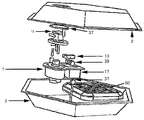
도 1은 제 1 가열기 요소를 구비하는 가열가능한 또는 냉각가능한 유체 백의 사시도이다.
도 2는 자기 스위치의 자기 스위치의 부품의 사시도이다.
도 3은 자기 스위치의 다른 부품의 사시도이다.
도 4는 제 1 가열기를 위한 케이싱의 내부 사시도이다.
도 5는 제 1 가열기의 사시도이다.
도 6은 백을 위한 하우징의 사시도이다.
도 6a는 도 6의 하우징의 평면도이다.
도 7은 하우징을 위한 단부 캡의 후방 사시도이다.
도 8은 블리드 홀 프로브의 사시도이다.
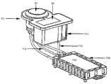
도 9는 가열가능한 유체 백을 위한 제 2 가열기 및 하우징의 사시도이다.
도 10은 가열가능한 유체 백을 위한 제 3 가열기의 부품의 사시도이다.
도 11은 도 10의 제 3 가열기를 구비하는 백의 사시도이다.
도 12는 가열가능한 유체 백을 위한 제 4 가열기 조립체의 사시도이다.
도 13은 도 12의 백의 저면도이다.
도 14는 도 12의 백의 측면도이다.
도 15는 도 12의 백의 평면도이다.
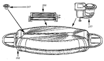
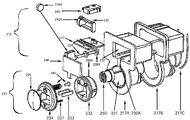
도 16은 제 5 가열기 요소를 구비하는 가열가능한 또는 냉각가능한 백의 사시도이다.
도 17은 도 16의 가열기 요소의 부품의 사시도이다.
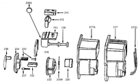
도 18은 전력 접속 및 안전 스위치 의 부품의 사시도이다.
도 18a는 도 18에 도시된 바와 같은 배열체의 후방 사시도이다.
도 18b는 측부 사시도이다.
도 18c는 안전 스위치 수단의 사시도이다.
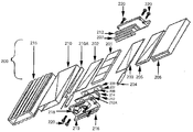
도 19는 도 18의 가열기 요소의 사시도이다.1 is a perspective view of a heatable or coolable fluid bag having a first heater element;
2 is a perspective view of a part of the magnetic switch of the magnetic switch.
3 is a perspective view of another part of the magnetic switch.
4 is an internal perspective view of the casing for the first heater.
5 is a perspective view of the first heater.
6 is a perspective view of a housing for a bag;
6A is a plan view of the housing of Fig.
7 is a rear perspective view of the end cap for the housing;
8 is a perspective view of a bleed hole probe.
9 is a perspective view of a second heater and a housing for a heatable fluid bag.
10 is a perspective view of a part of a third heater for a heatable fluid bag.
11 is a perspective view of a bag having the third heater of Fig.
12 is a perspective view of a fourth heater assembly for a heatable fluid bag.
13 is a bottom view of the bag of Fig.
14 is a side view of the bag of Fig.
15 is a plan view of the bag of Fig.
16 is a perspective view of a heatable or coolable bag having a fifth heater element.
Figure 17 is a perspective view of the components of the heater element of Figure 16;
18 is a perspective view of the components of the power connection and safety switch.
18A is a rear perspective view of the arrangement as shown in FIG.
18B is a side perspective view.
18C is a perspective view of the safety switch means.
Figure 19 is a perspective view of the heater element of Figure 18;
다음의 설명은 본 발명의 바람직한 실시형태, 즉 가열가능한 또는 냉각가능한 유체 백 및 가열기에 관련하여 본 발명을 설명한다. 가열가능한 유체 백은 유체에 대해 절연된 가열기 요소를 제공하는 것이 모색된다. 본 발명은 이러한 바람직한 실시형태에 결코 제한되지 않는데, 이들 실시형태는 단지 본 발명을 예시하기 위한 것이고, 또한 본 발명이 범위로부터 벗어나지 않는 한도 내에서 용이하게 변경 및 개조가 가능하기 때문이다.
The following description describes the present invention in relation to a preferred embodiment of the present invention, namely a heatable or coolable fluid bag and heater. It is contemplated that the heatable fluid bag provides a heater element insulated against the fluid. The present invention is by no means limited to these preferred embodiments, since these embodiments are merely intended to illustrate the present invention and are susceptible to modification and adaptation without departing from the scope of the present invention.
가열가능한 유체 백Heatable fluid bag
도 1 내지 20은 백(2), 유체(3) 및 가열기 요소를 위한 상이한 실시예를 보여주는 부품을 포함하는 가열가능한 유체 백(1)를 도시한다. 용기(2)는 외면(5), 내면(6), 측면, 및 연부(8)를 갖는 재료로 형성된다. 용기(2)는 내부에 유체(3)를 수용하기 위한 유체적으로 실링된 포위된 공간(8)을 제공하도록 적합된다. 1 to 20 show a heatable
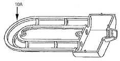
백(2)은 다음의 제 1 가열 요소(10)를 포함하는 적어도 하나의 가열기의 부품, 및 전력 접속 수단(11), 전기 회로(12) 및 적어도 하나의 자기 기계 스위치(13)의 스위치 부품을 포함하는 하우징을 포함한다. 전력 접속 수단(11)이 전력원에 접속되었을 때, 가열 요소(10)가 특정 시간 동안 특정 온도로 유체를 가열하도록, 스위칭 부품들은 백의 내부에서 함께 전기적으로 접속되도록 배치된다.The
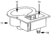
도 1, 4 및 5에 도시된 바와 같이, 가열 요소(10)는 백(2)의 내측 표면에 연결되어 지지되는 가열 케이지(10a) 내에 위치될 수 있다. 도 4는 조립된 가열기 케이지의 하나의 반쪽만을 도시한다. 가열 요소(10)는 커넥터(15) 및 접지 커넥터(16)를 구비하는 U자형 부재(14) 및 전열선을 포함할 수 있다. 전기 회로(12)는 배선 및 가열 요소(10)의 전열선을 전력 접속 수단(11)에 전기적으로 접속하는 적절한 접속을 포함한다. 전력 접속 수단(11)은 하우징(17) 내에 수용되고, 하우징은 또한 백(2)의 내측에 의해 지지될 수 있고, 전력원의 부품인 플러그용 소켓을 포함한다. 하우징(17)은 제거가능한 뚜껑을 구비하는 내부에 오목한 공간을 형성하는 사각 박스형 구조물을 포함할 수 있다.As shown in Figures 1, 4 and 5, the
사용 시, 전기식 고온 유체 백은 단순하게 전력원에 삽입되고, 특정 시간 동안 특정 온도까지 가열되도록 허용된다. 예를 들면, 백 및 전열선을 포함하는 요소(10)의 크기에 따라, 유체 및 백을 적절히 가열하기 위한 시간은 달라질 수 있으나, 일례로서 전형적인 휴대형 백의 경우 가열을 위해 10 분 밖에 필요하지 않다. 가열, 및 전력원으로부터의 접속차단 또는 단절 후, 가열된 백은 무엇이든지 가열할 수 있는 휴대형 기기로서 사용을 위한 준비 상태에 있고, 이와 같은 가열은 약 5 시간 동안 지속될 수 있다. In use, the electrical high temperature fluid bag is simply inserted into the power source and allowed to heat up to a specified temperature for a specified time. For example, depending on the size of the
자기 스위치(13)는 기체 압력의 축적 및 폭발을 방지하도록 적합되고, 단부(18)를 갖는 세장형 부재를 포함하고, 여기서 일단부(18)는 백의 내측의 일측에 위치되는 전기 회로(12)에 연결되고, 타단부(18)는 용기의 타측의 내측에 연결되고, 이것에 의해 전기 회로(11)는 백이 이 백의 내측면들 사이에서 특정 거리를 초과하거나 특정 압력을 초과하여 팽창하는 경우에 차단될 수 있다.The
하우징(17)은 백 내의 과잉 압력을 제거하도록 적합되는 하우징(17) 내에서 리세스 내에 위치되는 적어도 하나 변형가능한 개구(21)를 포함하는 전력 접속 수단에 인접하여 위치되는 적어도 하나의 블리드 밸브(20)를 포함한다. 도 8에 도시된 바와 같이, 고온 또는 냉각 유체 백은 하우징(17) 내에서 리세스 내에 제거가능하게 보관될 수 있는 프로브(23)를 포함할 수 있다. 프로브(23)는 더 두꺼운 단부에 헤드(25)를 구비하는 세장형의 테이퍼진 부재(24)로서 형성되고, 사용 시 사용자는 헤드를 파지하여 포위된 공간 내에 유지되는 공기 또는 기체를 배출 또는 방출시키도록 변형가능한 개구 내에 프로브를 밀어넣는다. 블리드 밸브(20)는 중앙 홀로서 형성되는 개구를 갖는 슬라이딩 가능하게 상호 로킹되는 2 개의 원형 튜브 부재로 구성되는 변형가능한 부재를 포함할 수 있다. The
모든 전기 회로, 커넥터, 배선 및 스위칭 부품을 위해 이중 절연이 제공된다. 백(2)은 임의의 적절한 형상을 가질 수 있고, 예를 들면, 적어도 하나의 층의 PVC를 포함하는 재료로 형성될 수 있다. 대안적으로 재료는 용접 이음매를 구비하는 3 개 층의 PVC의 외측 재료를 가질 수 있다. 하우징(17)은 온도 제어를 위한 적어도 하나의 온도자동조절기(32)를 포함한다. 도 4에 도시된 가열 케이지(10a)는 가열 요소, 전기 접속부 및 열 퓨즈(33)를 수용하고, 보호 및 방수를 위해 수지로 실링된다. 하우징(17)은 접지 접속을 점검할 수 있도록 적어도 하나의 접지 시험점(35)을 포함한다. 하우징(17)은 또한 전력이 회로에 접속되었음을 확인하기 위해 전력 접속부에 전기적으로 접속되는 표시등(36)을 포함할 수 있다. Double insulation is provided for all electrical circuits, connectors, wiring and switching components. The
도 1에 도시된 바와 같이, 전기 회로는 가열 요소(10)로부터 전력 접속 수단(11)까지 연장되는 적어도 이중 절연된 단일의 다발의 전선으로 형성된다. 자기 스위치(13)의 세장형 부재는 중실체이거나 중공체일 수 있는 튜브형 구조를 포함할 수 있다. 세장형 부재의 단부(17)는 내부에 슬롯(38)을 갖는 원형 헤드 구조(37)를 포함하는 연결 구조를 포함하고, 상기 슬롯은 일단부에 상보적 슬롯(40)을 구비하는 원형 헤드(39)를 구비하는 세장형 본체를 갖는 세장형 바 부재와 슬라이딩 가능하게 끼워맞춤되고, 본체의 나머지 부분은 원형 헤드(39)에 대향하는 단부에 단부 횡 바(43)를 구비하는 직사각형 단면의 2 개의 평행 바(41, 42)를 포함한다. As shown in Fig. 1, the electrical circuit is formed by at least a double insulated single bundle of wires extending from the
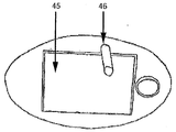
회로를 완성하기 위해, 헤드 및 슬롯은 상호 슬라이딩 결합하므로, 백이 지나치게 팽창하는 경우에는 일측이 세장형 부재를 취하고 있는 타측으로부터 멀어지는 방향으로 이동하고, 이것에 의해 헤드(37)은 헤드(39)의 슬롯으로부터 벗어나서 전기 회로를 차단시킨다. 도 7의 후면도에 도시된 바와 같이, 자기 스위치(13)를 포함하는 하우징의 적어도 일부는 피트(fit)에 포스트(46)에 의해 부착되는 제거가능한 커버(45)를 가질 수 있고, 홀(20a)에 부착된다. 도 6 및 6a는 회로를 제거한 하우징의 확대도를 도시한다.
In order to complete the circuit, the head and the slot are slidingly coupled to each other, so that when the bag is excessively expanded, one side moves in a direction away from the other side where the elongated member is taken, Out of the slot to interrupt the electrical circuit. 7, at least a portion of the housing, including the
제 2 가열기 요소 - 도 9 Second Heater Element - Figure 9
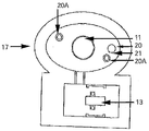
도 9는 제 1 가열기 요소와 유사하지만 제 2 가열기 요소라고 부를 수 있는 전력원에 전기 접속을 위해 돌출하는 2 개의 전선을 구비하는 형태의 가열기 요소의 다른 실시예를 도시한다. 또한 전력 접속 수단(11)을 차폐하기 위한 개방가능한 캡(47)이 도시되어 있다. 이 가열기 요소의 외부 케이싱은 이중 절연된 것으로 간주되도록 두껍거나 보강된 플라스틱으로 형성된다. 외부 케이싱은 금속 요소 또는 전극 상에 사출성형될 수 있는 열가소성물질일 수 있다.
Figure 9 shows another embodiment of a heater element in the form of a heater element having two wires projecting for electrical connection to a power source similar to the first heater element but which may be referred to as a second heater element. An
제 3 가열기 요소 - 도 10 및 11Third Heater Element - Figures 10 and 11
도 10 및 11에는 도 1, 4, 5 및 9의 가열기 요소(10)의 다른 다른 변형인 제 3 가열기 요소가 도시되어 있고, 이것은 고온 유체 백의 다른 부품에 전기적으로 접속되는 절연선의 상측 및 하측에 이중 절연층을 포함하는 가열기 요소(50)로 표시된다. 이 가열기 요소(50)는 층상의 평면형 절연 시트 부재 및 전도성 시트 부재로 구성되는 실질적으로 평면형인 부재로서 형성되고, 반면에 다른 가열 요소는 U자형이고, 이미 개시된 다른 부품, 즉, 백, 전력 접속 수단(11), 하우징(17) 및 기계적 자기 스위치(13), 블리드 홀(20), 표시등 및 온도자동조절기를 포함한다. 이러한 시트형 구조는 가열 면적 및 히트 싱크 전도성을 효과적으로 증가시키고, 이중의 독립적으로 절연된 개별적 실링 구조로서 설계된다. 온도 퓨즈는 전력 차단 수단으로서 가열기 요소(50) 내에 구축될 수 있다.10 and 11 illustrate a third heater element, which is another variation of the
이러한 가열 요소 실시예에서 전도 부재는 물에 열을 더 우수하게 분산 또는 소산시키도록 설계되는 알루미늄 재료일 수 있다. 요약하면, 교호 순서의 절연 부재 및 전도 부재가 있다. 가열기 요소(50)의 일측으로부터 출발하는 도 9에 도시된 바와 같이, 상면으로부터 출발하여 수개의 부품이 존재하지만 내부 부분을 참조하여 설명한다. In such a heating element embodiment, the conducting member may be an aluminum material designed to better dissipate or dissipate heat in the water. In summary, there is an alternating sequence of insulating and conducting members. Starting from one side of the
- 제 1 비전도성 외부 케이싱 부재(51)(플라스틱)The first unconducting outer casing member 51 (plastic)
- 제 1 외부 전도성 시트(52)(외부 알루미늄 셸)The first outer conductive sheet 52 (outer aluminum shell)
- 제 1 외부 절연 시트(53)(이중 마이카 시트)The first outer insulating sheet 53 (double mica sheet)
- 제 1 내부 전도성 시트(54)(내부 알루미늄 시트)The first inner conductive sheet 54 (inner aluminum sheet)
- 제 1 내부 절연 시트(55)(예를 들면, 4 mm 두께의 마이카 시트)A first inner insulating sheet 55 (e.g., a 4 mm thick mica sheet)
- 중간 외부 외주 링(56)(플라스틱 링)- Middle outer outer peripheral ring (56) (plastic ring)
전열선(57)을 위한 마이카 지지 골격 지지부재The mica support skeletal support member for the heating wire (57)
- 골격 지지부재(57)의 주위에 권취된 전열선(58) - the heating wire (58) wound around the frame supporting member (57)
- 제 2 내부 절연 시트(59)(마이카 시트)A second inner insulating sheet 59 (mica sheet)
- 제 2 전도성 시트(60)(알루미늄 시트)The second conductive sheet 60 (aluminum sheet)
- 제 2 외부 절연 시트(61)(이중 마이카 시트)The second outer insulating sheet 61 (double mica sheet)
- 제 2 외부 전도성 시트(62)(알루미늄 시트)The second external conductive sheet 62 (aluminum sheet)
- 제 2 비전도성 외부 케이싱 부재(63)(플라스틱)
A second nonconductive outer casing member 63 (plastic)
먼저, 부품은 외주의 만곡된 벽을 갖는 그리드형 패턴 부재로서 형성되는 플라스틱 보호 케이싱(51)의 형태의 제 1 비전도성 외부 케이싱 부재로 시작할 수 있다. 케이싱은 고온 플라스틱으로 형성될 수 있다. 외부 케이싱(51)의 하측에 직립 벽 및 수평 벽을 갖는 외주 부재로서 형성된 외부 알루미늄 셸의 형태의 열 및 전기 전도성 시트(52)이 있고, 이것에 의해 직립 벽은 제 1 비전도성 케이싱(51)의 만곡된 벽 내에서 슬라이딩 가능한 치수 및 형상을 갖고, 한편 수평 벽은 만곡된 벽의 연부(edge)와 접촉한다.First, the part may start with a first non-conductive outer casing member in the form of a plastic
외부 케이싱(51) 및 전도성 시트(52)의 하측에는 전도층(52)에 의해 경계를 이루는 면적보다 작은 면적에 걸쳐 연장하는 시트 재료로서의 마이카 재료로 형성되는 제 1 절연 시트(53)를 포함하는 재료의 조합이 있다. 제 1 시트(53)는 이중 시트로서 형성될 수 있다. 제 1 절연 시트(53)의 하측에는 제 1 절연 시트(53)와 유사한 면적의 알루미늄 시트 재료(예를 들면, 1 mm 두께의 포일)의 형태의 제 1 내부 전도성 시트(54)가 있다 내부 전도성 시트(54)의 하측에는 마이카 시트 재료(55)의 형태의 제 1 내부 절연 시트(55)가 있다. A first insulating sheet 53 formed of a mica material as a sheet material extending over an area smaller than an area bounded by the
제 2 절연 시트(55)의 하측에는, 예를 들면, 니켈 크로뮴 합금일 수 있는 전열선(58)을 지지하도록 설계 및 형성되는 마이카 골격 지지부재(57)가 있고, 전열선은 도 8에 도시된 바와 같이 골격 부재의 외부로 복귀하도록 평행 루프 내에서 골격 부재 내로 루프 상으로 연장되고, 고온 내열선 유선 접속에 의해 전력 접속 수단(11)에 접속된다.On the lower side of the
골격 부재(57) 및 전열선(58)의 하측에 접촉하여, 시트(55, 56)와 유사한 면적의 제 2 내부 절연 시트(59)가 있다. 제 2 내부 절연 시트(59)의 하측에 접촉하여, 또한 시트(59)와 유사한 면적을 갖는 치수인 제 2 내부 전도성 시트(60)가 있다. 그러나, 본 실시예에서, 제 2 내부 전도성 시트(60)는 시트가 연부에 의해 경계를 이루도록 형성된다.There is a second inner insulating
시트(60)의 하측에 접촉하여, 시트(59, 60)의 면적보다 큰 형상 및 치수를 갖는 제 2 절연 시트(61)가 있다. 또한 제 2 외부 절연 시트(61)의 하측에 접촉하여, 제 2 외부 전도성 시트(62)가 있다. 시트(61)는 이중 마이카 시트로서 형성될 수 있다. 시트(62)는 시트(59, 60)에 비해 넓은 면적을 갖는다. 마지막으로, 저단부 또는 대향 단부에는 내부에 개구를 갖는 평면의 그리드형 시트로서 형성되는 제 2 외부 케이싱(63)이 있다. There is a second insulating
위의 부품의 조립의 중간에, 중간 외부 외주 링 부재(66)는 세장형 벽 부재의 상부로부터 하부까지 연장하는 수직으로 연장하는 프롱 부재를 갖는 링형의 세장형 벽 부재로 형성된다. 상부를 위한 프롱 부재는 하부 프롱 부재와 정렬되거나 정렬되지 않을 수 있다. 상부 프롱 부재는 상부의 포위된 영역을 형성하도록 제 1 외부 케이싱(51) 내에서 그리고 및 하측에서 대응하는 치수 및 위치를 갖는 슬롯(도시되지 않음)과 슬라이딩 가능하게 끼워맞춤되도록 설계된다. 연부 부재(66)는 시트(53, 54, 55, 59, 60, 61)보다 큰 면적을 갖고, 시트(53, 54, 55, 57, 58)가 제 1 외부 케이스 부재(51) 및 중간 링 부재(56)에 수용될 수 있는 두께를 갖는다. In the middle of the assembly of the above components, the intermediate outer peripheral ring member 66 is formed of a ring-shaped elongated wall member having vertically extending forward members extending from the top to the bottom of the elongated wall member. The prong member for the upper portion may not be aligned or aligned with the lower prong member. The upper plunger member is designed to be slidably fitted with a slot (not shown) having a corresponding dimension and location in the first
중간 링 부재(66)의 타측 상에 하부 프롱 부재가 시트(59, 60, 61, 62)를 수용하도록 제 2 외부 케이싱 부재(63) 내의 대응하는 슬롯과 슬라이드 가능한 끼워맞춤되도록 형성된다.A lower plung member is formed on the other side of the intermediate ring member 66 so as to be slidably fitted with a corresponding slot in the second
내부 전도성 시트(60)는 오목한 영역을 형성하도록 4 개의 측부 중 적어도 3 개의 측부 상에 외부 외주 연부를 갖는 시트로서 형성되고, 이것에 의해 시트(59)는 상기 오목한 영역 내에 슬라이딩 가능하게 수용될 수 있다. 시트(59)의 상측에서, 가열된 선(58)을 구비하는 골격 부재(57)는 또한 시트(60)의 오목한 영역 내에 수용될 수 있다.The inner
제 1 및 제 2 내부 전도 시트(54, 60)(이것은 다음의 마이카 시트(55), 마이카 골격 지지 시트(57), 전선(58), 마이카 시트(59)를 포함한다)는 개재되는 상기 시트를 결합하도록 압축함과 동시에 물 또는 습기가 개입하는 것을 방지하도록 2 개의 알루미늄 시트를 함께 실링하는 임의의 적절한 수단에 의해 결합될 수 있다. 예를 들면, 이것은 용접에 의해 실행될 수 있다. 에폭시와 같은 다른 연결 및 실링 수단이 사용될 수 있다. 외부 케이싱 부재(51, 63)는, 예를 들면, 6 mm의 두께를 갖는 조립된 가열기 요소(50)를 형성하도록 함께 연결되거나 결합될 수 있다. 케이싱 부재는 하측의 조립체를 보호하고, 또한 시트 상에서 물의 순환을 허용하고, 또한 백 벽과의 직접 접촉으로부터 가열기 요소를 이격시키는 기능을 한다. 일례로서, 전력 요건은 450 와트의 전력의 110V 내지 220V일 수 있다. 전선은 1.5 mm의 간격으로 권취될 수 있고, 골격(57)은 90mm의 길이 x 40 mm의 폭 x 1 mm의 두께일 수 있다.
The first and second inner
냉각 유체 백Cooling fluid bag
본 발명은 유체(3)를 수용하기 위한 포위된 공간을 제공하도록 적합된 측면을 갖는 백을 포함하는 냉각 유체 백 및 자기 스위치(13)를 포함할 수 있다. 본 실시예에서, 유체는 냉장고 내에 둠으로써 냉각되도록 적합된다. 이 유체는 임의의 유형의 부동제 또는 부동제와 물의 혼합물 또는 냉각되거나 냉동될 수 있는 임의의 유체를 포함할 수 있다. 냉각 유체 백은 또한 적어도 하나의 블리드 밸브(20) 및 프로브를 포함할 수 있다.The present invention may include a cooling fluid bag and a magnetic switch (13) comprising a bag having a side adapted to provide an enclosed space for receiving the fluid (3). In this embodiment, the fluid is adapted to be cooled by being placed in the refrigerator. The fluid may include any type of antifreeze or mixture of antifreeze and water or any fluid that can be cooled or frozen. The cooling fluid bag may also include at least one
고온 유체 백에서와 같이, 자기 스위치(13)는 기체 압력의 축적 및 폭발을 방지하도록 적합되고, 단부를 갖는 세장형 부재를 포함한다. 세장형 부재의 일단부는 백의 내측의 일측에 위치되는 전기 회로(12)에 연결되고, 타단부(17)는 백의 타측의 내측에 연결된다. 전기 회로(12)는 백이 이 백의 측면들 사이에서 특정 거리를 초과하여 팽창하는 경우에 차단될 수 있다. 자기 스위치(13)의 구조는 고온 유체 백에 대해 설명한 것과 동일할 수 있다.
As in the high temperature fluid bag, the
제 4 가열기 요소 - 도 12 내지 도 15Fourth heater element - Figures 12 - 15
도 1 내지 도 11의 다른 백과 유사하게, 전력 접속 수단(111)을 갖는 하우징(117)에 전기적으로 접속되는 제 4 가열기 요소(110)가 도시되고, 내부에 유체를 구비하는 백(도시되지 않음) 내의 자기 스위칭 수단(113)은 도 1 내지 도 11의 다른 백의 구성과 유사하다. 본 실시예에서, 추가의 가열기 요소는 전력 접속 수단과 자기 스위칭 수단에 전기적으로 접속되는 3 개의 전선을 갖고, 전선 중 하나는 시험기 전선(119)이고, 다른 전선은 프롱을 요소에 전기적으로 접속시킨다. 또한 이 추가의 가열기 요소는 절연성 지지 케이지(116) 내에 수용된다.
A
제 5 가열기 요소 - 도 16 내지 도 19 Fifth Heater Element - Figures 16 to 19
본 실시예에서, 내부에 유체를 수용하는 백(202) 내의 하우징 내의 전력 접속 수단(217) 및 안전 스위치 수단(213)과 같은 모든 다름 부품과 작동 가능하게 결합되는 제 5 가열기 요소(200)가 있다. 또한 도 1 내지 도 15의 다른 백과 유사하게, 도 16 내지 도 20에 도시된 바와 같은 제 5 가열기 요소는 적어도 하나의 외부 하우징, 전력 접속 수단을 수용하기 위한 내부 하우징, 및 안전 스위치 수단을 갖는다. In this embodiment, a
전력 접속 수단은 온도자동조절기, 저항, 전력 플러그 하우징 베이스, 전기 프롱(예를 들면, 플러그 내에서 발견되는 것과 같음), 배선, 고정구, 플러그 홀더, LED, 단부 캡을 포함할 수 있다. 안전 스위치 수단은 스위치, 수평의 슬라이드, 커버, 일단부에 자석을 구비하는 세장형 부재, 다른 자석을 구비하는 슬롯형 바를 포함한다. 제 5 가열기 요소(200)는 중심으로부터 외방을 향하여 제 1, 제 2 및 제 3 조합의 부품을 포함한다.The power connection means may include a thermostat, a resistor, a power plug housing base, an electrical prong (such as found in a plug), a wire, a fixture, a plug holder, an LED, and an end cap. The safety switch means includes a switch, a horizontal slide, a cover, a elongated member with a magnet at one end, and a slotted bar with another magnet. The
제 1 조합은 중심으로부터 전기 접속 부재와 함께 수용되고 접촉되는 발열 부재(201)(예를 들면, PTC 정의 온도 계수 재료)를 포함하고, 전기 접속 부재는 발열 부재(201)에 직접적으로 접합되는 전선을 구비하는 전극 형태로 전력 접속 부재 수단을 포함할 수 있고, 또는 이것은 전기 회로의 일부인 제 1 외부 전극 플레이트 부재(202) 및 단부를 갖는 전기 회로의 다른 일부인 제 2 전극 플레이트 부재(203)로서 형성될 수 있다. 단부를 갖는 제 1 및 제 2 전극 플레이트 부재의 각각이나 적어도 전극은 일단부가 전력원에의 접속을 허용하도록 그것에 접속되는 전선(204)의 형태의 전력 또는 전기 접속부를 갖는다. The first combination includes a heating member 201 (for example, a PTC-defined temperature coefficient material) that is received and brought into contact with the electrical connecting member from the center, and the electrical connecting member is a wire that is directly connected to the
발열 부재(201)는 전기 에너지를 열 에너지로 변환시키기 위해 저항기로서 작용할 수 있어야 한다. 예를 들면, 단부를 갖는 발열 부재(201)는 치수 안정성, 내약품성을 갖는, 특히 고온 및 가수분해에 대한 저항이 큰 임의의 재료로 제작될 수 있다. 예를 들면, 발열 부재는 정의 온도 계수(PTC)를 포함할 수 있다. 전극 플레이트 부재(202, 203)는 예를 들면, 금, 은, 구리, 황동, 강, 스테인리스 강 또는 알루미늄과 같이 통전을 허용할 수 있는, 그리고 히트 싱크로서 작용할 수 있는 임의의 두께의 임의의 재료일 수 있다.The
제 1 및 제 2 전극 플레이트 부재(202, 203)를 완전히 수용하기 위해, 단부를 갖는 임의의 선택된 두께의 적어도 하나의 시트 또는 막 층의 형태의 부재(205)의 형태의 제 1 절연 부재 또는 층이 있고, 다음에 단부를 갖는 임의의 선택된 두께의 시트 부재(206)의 형태로 제 1 열전도층(206)이 접촉된다. 예를 들면, 막 층(205)은 폴리이미드 화합물로 형성될 수 있고, 이중 절연으로서 적층될 수 있다. 제 1 열전도성 시트 부재 또는 층(206)은 단부를 갖는 슬리브 형태이고, 이것은 알루미늄, 강, 구리 등과 같은 열을 전도할 수 있는 임의의 재료로 형성될 수 있다. 알루미늄은 경량이고 강도를 가지므로 유용하다. 열전도성 시트 부재의 단부는 내측의 단부 지지부재(207), 즉 쌍을 수용하도록 적합된다. 내측의 단부 지지부재는, 예를 들면, 플라스틱 또는 실리콘으로 제조되는 절연 부재로서 형성된다.In order to fully accommodate the first and second
제 1 조합은 제 2 및 제 3 조합을 포함하는 외부 조합을 지지하고 유지하는 대부분의 내부 조합이다. 내측의 단부 지지부재(207)는 단부 부재들 중 하나에 전선(들)(204)을 관통시키기 위한 적어도 하나의 외방향으로 돌출하는 개구 또는 홀(208)을 구비하는 평면형 캡으로서 형성되고, 각각의 캡의 일측 및 캡의 대향 측 상에는 제 1 및 제 2 외부 시트 부재를 포획하기 위한 크기 및 구성을 갖는 돌출하는 오목한 립 부분 또는 구조(209)가 있다. 홀(208)은 내측의 단부 지지부재(207) 중 적어도 하나 상에만 제공된다.The first combination is most of the inner combination that supports and maintains the outer combination including the second and third combinations. The inner
요약하면, 제 1 조합은, 예를 들면, 단면에서 상면으로부터 저면을 향하는 순서로 다음의 요소들을 포함할 수 있다. In summary, the first combination may include, for example, the following elements in order from the top surface to the bottom surface in cross section:
- 내측의 단부 지지부재(207)를 구비하는 제 1 열전도성 부재(206)(예를 들면, 알루미늄)A first thermally conductive member 206 (e.g., aluminum) having an inner
- 내부 절연층(205)의 이중 층- the inner layer (205) of the double layer
- 전극 플레이트(203)/발열 부재(201)/전선(204)을 구비하는 전극 플레이트(202)- Electrode plate (202) with electrode plate (203) / heating element (201) / wire (204)
- 이중 내부 절연층(205)- a double inner insulation layer (205)
- 내측의 단부 지지부재(207)를 구비하는 제 1 열전도성 부재(206)(예를 들면, 알루미늄)A first thermally conductive member 206 (e.g., aluminum) having an inner
제 1 조합의 수용 및 접촉의 외측에 제 1 조합의 제 1 열전도성 부재(206)와 접촉하는 제 2 절연 시트 부재 또는 층(210)을 포함하는 제 2 조합이 있다. 제 2 절연 시트 부재(210)는 단부를 갖도록 형성되는 세장형 슬리브로서 형성되고, 이것은 다른 절연 시트층(205)와 마찬가지로 임의의 두께 및 치수의 임의의 절연재로 형성될 수 있거나, 상기 임의의 절연재를 포함할 수 있고, 상기 임의의 절연재는, 예를 들면, 플라스틱 또는 폴리이미드와 같은 전기에 대한 물리적 장벽을 제공하도록 전도가 불가능하고, 그리고 임의의 유체로부터 실링될 수 있다. 제 2 절연 시트층 또는 부재(210)는 적어도 하나의 절연층으로 형성될 수 있다. 하나의 실시예에서, 제 2 절연 시트층(210)은 이중 절연된 부재일 수 있다.There is a second combination comprising a second insulation sheet member or
제 2 조합의 일부로서, 제 2 절연 시트층 또는 부재(210)를 수용 및 접촉하는 것은 개방 단부를 갖는 제 2 열전도층 또는 부재(215)이고, 개방 단부는 이전의 모든 시트를 그것의 적절한 분리된 위치에 지지 및 유지하는 중간의 단부 지지부재(212)에 의해 캐핑(capping) 및 고정된다. 중간의 단부 지지부재(212)는 내측의 단부 지지 부재와 형상 및 재료가 유사하지만 내부 지지부재보다 면적이 크고, 중간의 단부 지지부재(212) 중 하나 상의 전선(204)을 위한 유사한 개구 또는 홀(212a)은 내측의 단부 지지부재의 다른 홀(208)과 정렬되고, 그러나 립의 형태(214)는 제 2 열전도성 슬리브 부재(215)의 단부 내에 끼워맞춤되도록 적합된다. 전기 커넥터(210a)는 제 1 열전도성 슬리브 부재(206)에 의해 전기적으로 지지되지만, 전극(202 또는 203)에 전기적으로 접속된다.As part of the second combination, receiving and contacting the second insulating sheet layer or
제 2 조합의 수용 및 접촉의 외측에 제 3 조합이 있다. 제 3 조합은 중간의 단부 지지부재(212)보다 넓은 면적의 외측의 단부 지지부재(216)를 포함한다. 외측의 단부 지지부재(216)는 상호에 대해 그들의 적절한 위치에서 모든 시트 및 슬리브 부재의 다양한 조합을 유지하기 위해 중간의 단부 지지부재(212)와 접촉한다. 외측의 단부 지지부재(216)는 또한 립을 가지지 않지만 푸트(219)를 갖는 전선(204)을 위한 캡의 하나의 외측에서 돌출하는 개구 또는 홀(218)을 갖고, 이것에 이해 외측의 단부 지지부재는 L자형 단면을 갖고, 푸트(219)는 체결구, 접착제, 열 실링 또는 브래킷 등을 포함하는 임의의 적절한 수단에 의해 백에 고정될 수 있도록 슬롯을 갖는다. 외측의 단부 지지부재(216)는 반드시 절연재로 형성되지는 않고, 제 2 열전도성 슬리브(215) 및 백(202)에 대한 적절한 지지 및 연결을 가능하게 하는 임의의 재료로 형성된다. There is a third combination outside of the reception and contact of the second combination. The third combination includes an outer
조립되었을 때, 전선(204)이 제 1 및 제 2 시트(202, 203)로부터 열 요소의 외방으로 전력 접속 수단(211)을 향해 연장할 수 있도록 모든 개구 또는 홀(208, 212a, 218)은 정렬된다(슬라이딩 가능하게 끼워맞춤되는 돌출하는 절두 원추형 형상을 포함할 수 있다). 외측의 단부 지지부재(216)는 또한 고정 수단(220)을 가질 수 있고, 이것에 의해 적절한 체결구 및/또는 피팅(예를 들면, 볼트 및/또는 브래킷 및/또는 클램프)은 외부 알루미늄 슬리브에 외측의 단부 부재를 부착하도록 삽입되어, 모든 가열기 요소의 부품을 고정상태로 그리고 작동가능하게 상호 연결된 상태로 유지할 수 있다. 외측의 단부 지지부재 홀(218)은 이것을 통한 유체의 유입을 방지하기 위해 전선(208)의 주위에서 실링된다.When assembled, all openings or
중간의 단부 지지부재(212)는 외측의 단부 지지부재(216)로부터 제 2 열전도성 슬리브(215)까지 체결구(220)의 부착을 위한 노출된 오목한 외주 단부 연부를 남기도록 제 2 열전도성 슬리브 부재(215)의 단부 연부의 일부만을 접촉하는 치수의 면적을 갖고, 이것에 의해 외측의 단부 지지부재는 노출된 단부로부터 이격되어 간극을 형성하고, 체결구 만이 이들 사이의 간극을 가교를 형성한다. 다른 선택지에서, 노출된 단부가 존재하지 않을 수 있고, 이것에 의해 체결구(220)가 제 2 열전도 부재(215)와 맞물리도록 중간의 단부 지지부재를 통해 연장하도록 외측의 단부 지지부재는 중간의 단부 지지부재와 중첩된다.The intermediate
도 18, 18a, 및 18b에 도시된 바와 같이, 하우징(217)은 이중 절연된 하우징을 형성하도록 내부 하우징(217a) 및 외부 하우징(217b)을 포함한다. 또한 내부 하우징(217a)에 지지 및 부착되는 전력 접속 수단(217) 및 전기 고장 또는 백의 파열 또는 유체의 손실 등과 같은 임의의 이유로 백 또는 요소(200)에의 전력의 차단 방법으로서 작용하는 전력 접속 수단(217)에 전기적으로 접속되는 안전 스위치 수단(213)이 포함된다. 예를 들면, 자기 스위칭 수단 또는 전자 퓨즈 또는 솔레노이드와 같은 임의의 유형의 오버라이드가 가능하다.18, 18A, and 18B, the
외부 하우징(217b)은 유체 및 수전부(power inlet)를 전기적으로 연결할 수 있는 임의의 수단을 포함하는 전력 접속 수단(217)을 열 요소 및/또는 열 발생기(201) 및/또는, 예를 들면, 무선 또는 유선 접속부(들)(217c)와 같은 전극 플레이트(202, 203)에 대면 또는 접촉시키도록 적어도 백의 내측(202)에 물리적으로 연결된다. 유선 접속부(217c)는 2 개 이상의 전선으로 구성되는 하나의 케이블의 형태일 수 있고, 또는 전선 전도성 시험 수단을 구비하는 별도의 전선(210a)이 있을 수 있다. The outer housing 217b may be connected to the power connection means 217, including the fluid and any other means capable of electrically connecting the power inlet, to the heat elements and / or
내부 하우징(217a)은, 예를 들면, 직사각형의 형상을 가질 수 있는 안전 스위치 리세스(230) 및, 예를 들면, 원형의 형상을 가질 수 있는 전력 접속 리세스(231)를 포함한다. 전력 접속 리세스(231)에 의해 작동가능하게 접속 및 지지되는 전력 접속 수단(217)은 전기 프롱(233)을 위한 (예를 들면, 내부에 직사각형 리세스를 구비하는 원통형 형상일 수 있는) 플러그 하우징 베이스(232)를 포함하고, 다음에 (예를 들면, 직사각형 리세스를 갖는 직사각형 리세스 형상의 원통형 본체의 상면에 원형 링을 포함할 수 있는) 플러그 홀더(234)가 배치되고, 이것은 직사각형 리세스의 베이스를 통해 상방향으로 돌출하도록 프롱(233)으로부터 벗어나도록 플러그 하우징 베이스 상에 슬롯을 형성한다. The inner housing 217a includes, for example, a
마지막으로, (예를 들면, 고정용 포스트를 구비하는 원형 형상을 가질 수 있는) 전력 접속 단부 캡(236)이 있고, 이것은 전력원에 접속되도록 프롱(233)에의 접근을 가능하게 한다. LED 형태의 전등(237)이 포함될 수 있고, 이것은 전력이 온 또는 오프인지를 보여준다. 플러그 홀더(234)에 대한 캡(236)을 위한 이동가능한 고정은 스프링 및 볼트 체결구(240)를 포함할 수 있으나, 캡(236)의 하측의 포스트를 홀더(234) 내의 포스트 베이스 리세스 내에 부착하기 위해 다른 유형의 고정도 가능하다. 조립되었을 때, 홀더(234)의 돌출하는 리세스는 하우징 베이스(232)의 리세스 내로 슬라이딩 진입한다.Finally, there is a power connection end cap 236 (which may, for example, have a circular shape with a securing post), which allows access to the
전력 접속 리세스(231)에 인접하는, 그리고 접속 리세스(230a)에 의해 접합되는 안전 스위치 리세스(230)는 안전 스위치 수단(213)을 포함한다. 안전 스위치 수단(213)은 단부를 갖는 세장형 부재(238)을 포함하고, 일단부는 리세스(230)의 양측 상에서 수평의 슬라이드 플레이트(243) 상에/내에 슬라이딩 가능하게 장착되는 슬롯을 갖는 세장형 이중 바(242) 내에서 적어도 하나의 자석(238a)에 의해 전력 접속 수단과 전기적으로 접속되고(도면은 바(242) 내에서 내부 하우징(217a)의 리세스 내로 세장형 부재(238)와 함께, 스위치(245)를 장착하는 기능을 하는 하나의 슬라이드만을 도시한다), 개구(241)를 통해 돌출하는 일단부에 위치된 적어도 하나의 자석(242a)을 포함한다. 조립되었을 때, 자석(238a)은 전력 접속 수단으로부터 요소까지의 전력 접속을 완성하기 위해 이들 사이의 자기 접속을 형성하도록 직접적으로 또는 간접적으로 접촉한다. 세장형 부재(238)의 말단부(238b)는 리세스(230) 내의 개구(241)를 통해 돌출하고, 백의 대향하는 내측 벽에 연결되거나 접합되도록 연장하므로, 백이 지나치게 팽창하거나 또는 원하는 수준 또는 압력까지 팽창하는 경우, 세장형 부재(238)는 전력 접속 수단의 대향 단부에서 전기 접속에 관하여 자석(238a) 대 자석(242a)의 연결을 차단하도록 백의 벽과 함께 이동한다. 안전 스위치 수단(213)은 접속 리세스(230a)를 통해 전력 접속 수단에 전기적으로 접속되는 스위치(245)(예를 들면, 마이크로 스위치)를 포함한다. 리세스(230)는 제거가능한 커버 캡(246)을 갖는다.The
(예를 들면, 튜브형 형상을 가질 수 있는) 온도자동조절기(250) 및 저항기(250a)는 특정 온도에 도달할 때마다 백에의 전력을 자동적으로 차단하도록 전력 접속 리세스(231)와 함께 작동가능하게 포함될 수 있는 선택적 특징으로서 포함될 수 있다. 다른 변형례와 마찬가지로 임의의 이전의 부품이 조합되거나 포함될 수 있다. 백을 온수용 물병 또는 냉각 백으로서 사용할 수 있도록 유체는 부동제를 포함할 수 있거나 포함하지 않을 수 있다. 본 발명의 백은 - 10℃ 내지 100℃의 온도 범위로 냉각 및 가열되도록 설계되지만, 임의의 온도가 가능하다. 백은 공기 또는 유체의 유입 또는 배출을 가능하게 하는 적어도 하나의 개방가능한 그리고 폐쇄가능한 백 개구(247)를 포함한다. 백 개구(247)는 단순 가압 배출식 밸브 또는 도 16에 도시된 바와 같이 홀형 밸브 내의 플러그를 포함할 수 있다.The
본 명세서에서 설명되거나 청구된 바와 같은 제품, 방법 또는 공정의 경우에, 개별 부품 또는 "부품의 키트"와 같이 불완전 제품으로 판매되는 것과 같은 실시는 본 발명의 범위 내에 포함되는 것으로 이해될 것이다.In the case of products, methods, or processes as described or claimed herein, implementations such as sold as incomplete products, such as discrete components or "kits of components" will be understood to fall within the scope of the present invention.
본 발명의 이들 및 다른 기구 및 특징 뿐만 아니라 작동 방법 및 관련된 구조물의 요소의 기능 및 부품의 조합 및 제조의 경제는 본 명세서의 일부를 형성하는 첨부한 도면을 참조하는 다음의 설명을 고려하면 더 명확해질 것이고, 도면에서 유사한 참조번호는 다양한 도면에서 대응하는 부품을 지칭한다.These and other implementations and features of the present invention, as well as the functioning of the components and methods of operation and associated structures, and the economics of manufacture thereof, will be more clearly understood from the following description taken in conjunction with the accompanying drawings, which form a part hereof Like reference numerals in the drawings refer to corresponding parts in the various figures.
이하에서 설명의 목적을 위해, 용어 "상부", "하부", "우측", "좌측", "수직", "수평", "상면", "저면, "횡방향", "종방향" 및 그 파생어는 도면에서의 본 발명의 배향에 관련된다. 그러나, 본 발명은 반대의 뜻이 명시되는 경우 외에는 다양한 대안적 변형을 취할 수 있다는 것을 이해해야 한다. 또한 첨부된 도면에 도시된, 그리고 이하의 명세서에 설명된 구체적인 기기는 단순히 본 발명의 예시적 실시형태임을 이해해야 한다. 그러므로 본 명세서에 개시된 실시형태에 관련된 구체적 치수 및 기타 물리적 특징은 제한으로서 간주되지 않는다.
The terms "top", "bottom", "right", "left", "vertical", "horizontal", "top", "bottom", "lateral", " It should be understood, however, that the present invention may assume various alternative modifications, except where the contrary is expressly stated. Also, it is to be understood that the present invention is not limited to the embodiments shown in the accompanying drawings, It is to be understood that the specific devices described in the specification are merely exemplary embodiments of the invention and that specific dimensions and other physical features associated with the embodiments disclosed herein are not to be regarded as limitations.
장점Advantages
a) 전기 쇼크 예방a) Prevention of electric shock
b) 이중 절연된 가열기 요소b) Double insulated heater element
c) 공기의 방출 또는 유출 가능c) Air can be released or released
d) 백이 지나치게 팽창하는 경우에 스위치의 차단 가능d) Switch can be shut off if the bag is over-expanded
e) 적절한 가격e) Appropriate price
f) 가열 또는 냉각이 용이f) Easy to heat or cool
g) 장기간 열 유지g) Long-term heat retention
h) 많은 안전 기구h) Many safety mechanisms
i) 인가된 관계당국에 의한 시험i) Testing by authorized authorities
j) 침대 가온기 또는 개인 가온기로서 사용 가능j) Can be used as bed warmer or personal warmer
k) 가열가능한 백 또는 냉각가능한 백으로서 사용 가능k) Can be used as a heatable bag or as a coolable bag
l) 사용의 편리
l) Convenient use
변형례Modifications
본 명세서의 설명의 전체를 통해, 용어 "포함하다" 및 이것의 변형인 "포함하는"은 다른 첨가물, 부품, 완전체 또는 단계들을 배제하려는 의도를 갖지 않는다. 백은 예상되는 사용의 유형에 따라 직사각형 또는 세장형과 같은 임의의 적절한 형상으로 형성될 수 있다. 백 자체는 무엇이든지 가열 또는 냉각하기 위해 사용되거나, 예를 들면 침대 가온기와 같은 본체의 임의의 일부로서 또는 허리나 목을 위한 개인적 가온기로서 사용될 수 있다. 가열 요소는 말발굽형상 또는 플레이트상으로서 도시되어 있으나 임의의 형상을 가질 수 있다. 선택적으로 백은 외관을 개선 또는 변화시키기 위해, 그리고 더 우수한 열 유지 또는 쾌적함을 제공하기 위해, 예를 들면, 양피 커버와 같은 다양한 커버를 포함할 수 있다.Throughout the description of the present specification, the word " comprises "and variations thereof as" comprising " are not intended to exclude other additives, parts, integers or steps. The bag may be formed into any suitable shape, such as a rectangular or elongated shape, depending on the type of use expected. The bag itself may be used to heat or cool anything, or may be used as an optional part of the body, for example a bed warmer, or as a personal warmer for the waist or neck. The heating element is shown as a horseshoe or plate-like shape, but may have any shape. Optionally, the bag may include various covers, such as sheepskin covers, for example to improve or change the appearance and to provide better heat retention or comfort.
본 명세서에서 설명되거나 청구된 바와 같은 제품, 방법 또는 공정의 경우에, 개별 부품 또는 "부품의 키트"와 같이 불완전 제품으로 판매되는 것과 같은 실시는 본 발명의 범위 내에 포함되는 것으로 이해될 것이다. 본 발명의 이들 및 다른 기구 및 특징 뿐만 아니라 작동 방법 및 관련된 구조물의 요소의 기능 및 부품의 조합 및 제조의 경제는 본 명세서의 일부를 형성하는 첨부한 도면을 참조하는 다음의 설명을 고려하면 더 명확해질 것이고, 도면에서 유사한 참조번호는 다양한 도면에서 대응하는 부품을 지칭한다.In the case of products, methods, or processes as described or claimed herein, implementations such as sold as incomplete products, such as discrete components or "kits of components" will be understood to fall within the scope of the present invention. These and other implementations and features of the present invention, as well as the functioning of the components and methods of operation and associated structures, and the economics of manufacture thereof, will be more clearly understood from the following description taken in conjunction with the accompanying drawings, which form a part hereof Like reference numerals in the drawings refer to corresponding parts in the various figures.
가열기 요소(10, 50, 110, 200)의 경우, 전열선이 적절히 절연되도록 절연성 시트 및 전도성 시트의 수, 두께, 및 층 또는 시트의 형상은 임의로 선택할 수 있다. 백의 다른 용도를 위해, 즉 가열가능한 백으로의 용도 대신에, 백을 위한 유체는 부동제와 같은 다른 첨가제를 포함할 수 있고, 또는 백의 냉각이 가능하도록 물과 함께 부동제와 같은 냉동가능한 재료일 수 있다. 대안적으로, 백으로부터 유체 또는 물은 배출될 수 있고, 따라서 교체될 수 있다. 일반적으로, 유체는 - 10 ℃ 내지 100 ℃의 범위 내에서 냉각 및 가열되도록 설계될 수 있다. 임의의 온도 범위가 가능하다. "백"이라는 용어가 사용되었으나, 예를 들면, 발 가온기, 가열 패드, 용기 또는 파우치와 같은 상이한 용도에 관련된 동등한 다른 용어가 사용될 수도 있다.In the case of the
예를 들면, 도 16 내지 19과 같은 도에 도시된 바와 같이, 전극 플레이트는 직사각형일 수 있고, 절연층은 시트 또는 슬리브로서 형성될 수 있고, 열전도체 형상도 시트 또는 슬리브로서 형성될 수 있다. 층의 수는 임의의 수일 수 있다. 예를 들면, 열전도성 시트(215)는 가열기 요소로부터의 열 전달을 더 보조하기 위해 상부 및 하부면이 그루브를 갖는 슬리브로서 형성될 수 있다. 또한 열전도성 시트(215)는 열전도성 시트(215)에 외측의 단부 지지부재(216)를 제거가능하게 부착하도록 고정 수단(219a)을 수용하기 위한 나사산을 갖는 홀을 갖는다. 단부 캡(207, 212)은 내단부 캡(207)보다 큰 단부 캡(212)을 구비하는 직사각형 형상을 가질 수 있다. For example, the electrode plate may be rectangular, the insulating layer may be formed as a sheet or a sleeve, and the heat conductor shape may also be formed as a sheet or a sleeve, as shown in Figs. The number of layers may be any number. For example, the thermally
이하에서 설명의 목적을 위해, 용어 "상부", "하부", "우측", "좌측", "수직", "수평", "상면", "저면, "횡방향", "종방향" 및 그 파생어는 도면에서의 본 발명의 배향에 관련된다. 그러나, 본 발명은 반대의 뜻이 명시되는 경우 외에는 다양한 대안적 변형을 취할 수 있다는 것을 이해해야 한다. 또한 첨부된 도면에 도시된, 그리고 이하의 명세서에 설명된 구체적인 기기는 단순히 본 발명의 예시적 실시형태임을 이해해야 한다. 그러므로 본 명세서에 개시된 실시형태에 관련된 구체적 치수 및 기타 물리적 특징은 제한으로서 간주되지 않는다.The terms "top", "bottom", "right", "left", "vertical", "horizontal", "top", "bottom", "lateral", " It should be understood, however, that the present invention may assume various alternative modifications, except where the contrary is expressly stated. Also, it is to be understood that the present invention is not limited to the embodiments shown in the accompanying drawings, It is to be understood that the specific devices described in the specification are merely exemplary embodiments of the invention and that specific dimensions and other physical features associated with the embodiments disclosed herein are not to be regarded as limitations.
물론 전술한 내용은 본 발명의 예시적 실시예를 통해 제공되었으나, 본 기술분야의 당업자에게 명백한 이와 같은 모든 개조 및 변형 또는 다른 개조 및 변형은 이상에서 설명된 바와 같은 본 발명의 넓은 범위 내에 속하는 것으로 간주됨을 알 수 있을 것이다. It is to be understood that whilst the foregoing is provided by way of illustrative embodiments of the invention, it is intended that all such adaptations and modifications or other modifications and variations be apparent to those skilled in the art to which the invention pertains You will see that it is considered.
Claims (14)
상기 전력 접속 부재 수단은 전극 플레이트 부재들 사이에 상기 발열 부재를 개재하는 상기 발열 부재에 전기적으로 접속되는 상기 전극 플레이트 부재의 형태로 적어도 하나의 전극을 포함하고, 상기 전력 접속 부재 수단은 상기 가열기 요소와 상기 전력 접속 수단 사이의 전력 접속을 허용하도록 각각의 전극 플레이트 부재에 전기적으로 접속되는 적어도 하나의 전선을 포함하는, 가열가능한 유체 충전된 백을 위한 가열기 요소.The method according to claim 1,
Wherein the power connection member means includes at least one electrode in the form of the electrode plate member electrically connected to the heating member via the heating member between the electrode plate members, And at least one electric wire electrically connected to each of the electrode plate members to allow a power connection between the electrode connection member and the power connection means.
상기 가열기 요소는 단부를 갖는 제 2 절연층, 단부를 갖는 제 2 열전도층 및 중간의 단부 지지부재를 포함하고, 상기 제 2 절연층은 상기 제 1 열전도층을 피복하고, 슬리브의 형태이고, 다음에 상기 제 2 절연층을 피복하는 슬리브 형상의 상기 제 2 열전도층이 배치되고, 이것에 의해 상기 중간의 단부 지지부재는 절연재로 형성되고, 상기 내측의 단부 지지부재를 차폐하도록, 그리고 상기 내측의 단부 지지부재와 접촉하도록 상기 제 2 절연 부재 및 제 2 열전도 부재의 단부 내에 슬라이딩 가능하게 끼워맞춤되도록 적합되고, 적어도 하나의 중간의 단부 지지부재는 상기 전력 접속 부재 수단의 통과를 허용하기 위한 적어도 하나의 개구를 갖는, 가열가능한 유체 충전된 백을 위한 가열기 요소.3. The method according to claim 1 or 2,
Wherein the heater element comprises a second insulating layer having an end, a second thermally conductive layer having an end, and an intermediate end support member, the second insulating layer covering the first thermally conductive layer, in the form of a sleeve, The intermediate second end portion supporting member is formed of an insulating material so as to shield the inner end end supporting member, and the inner end supporting member is formed so as to cover the inner end supporting member, And at least one intermediate end support member is adapted to be slidably fitted in the end of the second insulating member and the second heat conductive member so as to come into contact with the end support member, Wherein the heating element has an opening in the heating element.
상기 발열 부재는 정의 온도 계수(PTC)로 형성되고, 상기 제 1 절연층 및 제 2 절연층은 플라스틱으로 형성되고, 상기 제 1 열전도층 및 제 2 열전도층은 슬리브의 형상의 금속으로 형성되고, 상기 내측의 단부 지지부재 및 중간의 단부 지지부재는 돌출하는 오목한 립 부분을 구비하는 내측을 구비하는 플레이트 캡 형상의 부재로서 형성되고, 상기 개구는 상기 립 부분의 것에 대해 상기 플레이트 캡의 대향측 상의 돌출하는 원통형 부재로서 형성되는, 가열가능한 유체 충전된 백을 위한 가열기 요소.4. The method according to any one of claims 1 to 3,
Wherein the heating member is formed of a positive temperature coefficient (PTC), the first insulating layer and the second insulating layer are formed of plastic, the first heat conductive layer and the second heat conductive layer are formed of metal in the shape of a sleeve, The inner end support member and the intermediate end support member are formed as a plate cap-shaped member having an inner side having a projecting concave lip portion, the opening being formed on the opposite side of the lip portion A heater element for a heatable fluid-filled bag, the heater element being formed as a protruding cylindrical member.
외측의 단부 지지부재는 상기 제 2 열전도층의 각각의 단부 상에 상기 중간의 단부 지지부재를 접촉시키고, 이것에 의해 적어도 하나의 외측의 단부 지지부재는 유체를 배제하도록 실링될 수 있는 상기 전력 접속 부재가 관통하여 연장하는 개구를 갖고, 상기 내측, 중간 및 외측의 단부 지지부재의 개구는 모든 개구를 통한 전기 접속을 허용하도록 정렬되고, 각각의 외측의 단부 지지부재는 상기 백의 내측에 연결할 수 있도록, 그리고 상기 제 2 열전도 부재의 단부에 고정되도록 적합된 푸트(foot)를 구비한 L자형인, 가열가능한 유체 충전된 백을 위한 가열기 요소.5. The method of claim 4,
Wherein the outer end support member contacts the intermediate end support member on each end of the second thermally conductive layer such that the at least one outer end support member can be sealed to eliminate fluid, Wherein the openings of the inner, intermediate and outer end support members are aligned to allow electrical connection through all of the openings, each of the outer end support members being connectable to the inside of the bag And an L-shaped, with a foot adapted to be secured to an end of the second thermally conductive member.
상기 제 1 및 제 2 절연층은 각각 이중 절연층으로서 형성될 수 있는, 가열가능한 유체 충전된 백을 위한 가열기 요소. 6. The method of claim 5,
Wherein the first and second insulating layers can each be formed as a double insulation layer.
상기 가열기 요소는 단부를 갖는 제 2 절연층, 단부를 갖는 제 2 열전도층 및 중간의 단부 지지부재를 포함하고, 상기 제 2 절연층은 상기 제 1 열전도층을 피복하고, 슬리브의 형상이고, 다음에 상기 제 2 절연층을 피복하는 슬리브로서 형성되는 상기 제 2 열전도층이 배치되고, 이것에 의해 상기 중간의 단부 지지부재는 절연재로 형성되고, 상기 내측의 단부 지지부재를 차폐하도록, 그리고 상기 내측의 단부 지지부재와 접촉하도록 상기 제 2 절연 부재 및 상기 제 2 열전도 부재의 단부 내에 슬라이딩 가능하게 끼워맞춤되도록 적합되고, 적어도 하나의 중간의 단부 지지부재는 상기 전기 접속 부재의 통과를 허용하는 적어도 하나의 개구를 갖고, 외측의 단부 지지부재는 상기 제 2 열전도층의 각각의 단부 상에 상기 중간의 단부 지지부재를 접촉시키고, 이것에 의해 적어도 하나의 상기 외측의 단부 지지부재는 유체를 배제하도록 실링될 수 있는 상기 전기 접속 부재를 위한 개구를 갖고, 상기 내측, 중간 및 외측의 단부 지지부재의 개구는 모든 개구를 통한 전기 접속을 허용하도록 정렬되고, 각각의 외측의 단부 지지부재는 상기 백의 내측에 연결할 수 있도록, 그리고 상기 제 2 열전도 부재의 단부에 고정되도록 적합된 푸트를 구비한 L자형인, 가열가능한 유체 충전된 백.8. The method of claim 7,
Wherein the heater element comprises a second insulating layer having an end, a second thermally conductive layer having an end, and an intermediate end support member, the second insulating layer covering the first thermally conductive layer, the shape of the sleeve, And the second heat conductive layer formed as a sleeve covering the second insulating layer is disposed on the inner end supporting member so that the intermediate end supporting member is formed of an insulating material and is configured to shield the inner end supporting member, And at least one intermediate end support member is adapted to be slidably fitted in the end of the second insulating member and the second heat conductive member so as to come into contact with the end support member of the at least one And the outer end supporting member contacts the intermediate end supporting member on each end of the second thermally conductive layer, Whereby at least one of the outer end support members has an opening for the electrical contact member that can be sealed to exclude fluid, the openings of the inner, intermediate and outer end support members being electrically connected through all openings And each outer end support member is connectable to the inside of the bag and has a foot adapted to be secured to an end of the second thermally conductive member.
상기 하우징은 상기 전력 접속 수단을 위한 적어도 하나의 리세스를 포함하는 적어도 하나 내부 하우징을 포함하고, 상기 전력 접속 수단을 위한 리세스는 플러그 하우징 베이스 및 플러그 홀더를 포함하고, 상기 플러그 하우징 베이스는 상기 내부 하우징 내에 슬라이딩 가능하게 끼워맞춤되도록 적합되고, 그리고 내부에 리세스를 구비하는 원통형으로 성형되고, 상기 플러그 홀더는 전기 프롱 및 이것에 후속되는 플러그 프롱 홀더 피팅(fitting) 및 이것에 후속되는 상기 백에 부착될 수 있는 접근 단부 캡을 수용하도록 적합되는 플러그 리세스를 구비하는 원통형 캡을 갖고, 상기 내부 하우징은 또한 안전 스위치 수단을 위한 다른 리세스를 갖고, 상기 안전 스위치 수단은 슬라이드 하우징, 스위치, 자석을 구비하는 바 부재, 및 자석을 구비하는 세장형 부재를 포함하고, 상기 세장형 부재의 일단부는 상기 백의 내측에 접합되고, 타단부는 자석의 접촉에 의해 전력 접속 부재 수단에 의해 스위치 및 전력 접속 수단에 작동 가능하게 연결되고, 이것에 의해 상기 슬라이드 하우징은 상기 바 부재, 스위치 및 상기 자석을 갖는 상기 세장형 부재의 일단부를 유지하고, 상기 세장형 부재를 구비하는 상기 백의 벽의 팽창으로 인해 상기 자석은 상기 안전 스위치 수단에의 상기 전력 접속 수단을 분리시켜 상기 전력원에 비전기적으로 연결되도록 하는, 가열가능한 유체 충전된 백.9. The method of claim 8,
Wherein the housing comprises at least one internal housing including at least one recess for the power connection means, the recess for the power connection means comprises a plug housing base and a plug holder, The plug holder being adapted to be slidably fitted in the inner housing and being formed into a cylindrical shape having a recess therein, the plug holder having an electric prong, followed by a plug prong holder fitting, Said housing having a further recess for a safety switch means, said safety switch means comprising a slide housing, a switch, a switch housing, A bar member having a magnet, and a long member having a magnet Wherein one end of the elongate member is joined to the inside of the bag and the other end is operatively connected to the switch and the power connecting means by the power contact member means by the contact of the magnet, Wherein the housing holds one end of the bar member, the switch and the elongated member with the magnet, and the magnet causes the power connection means to the safety switch means due to the expansion of the wall of the bag with the elongate member And to be disconnected to be non-electrically connected to the power source.
상기 발열 부재는 정의 온도 계수(PTC)로 형성되고, 상기 제 1 절연층 및 제 2 절연층은 플라스틱으로 형성되고, 상기 제 1 열전도층 및 제 2 열전도층은 슬리브의 형상의 금속으로 형성되고, 상기 내측의 단부 지지부재 및 중간의 단부 지지부재는 돌출하는 오목한 립 부분을 구비하는 내측을 구비하는 플레이트 캡 형상의 부재로서 형성되고, 상기 개구는 상기 립 부분의 것에 대해 상기 플레이트 캡의 대향측 상의 돌출하는 원통형 부재로서 형성되는, 가열가능한 유체 충전된 백.10. The method of claim 9,
Wherein the heating member is formed of a positive temperature coefficient (PTC), the first insulating layer and the second insulating layer are formed of plastic, the first heat conductive layer and the second heat conductive layer are formed of metal in the shape of a sleeve, The inner end support member and the intermediate end support member are formed as a plate cap-shaped member having an inner side having a projecting concave lip portion, the opening being formed on the opposite side of the lip portion A heatable fluid-filled bag formed as a cylindrical member that protrudes.
상기 제 1 절연층, 제 2 절연층 및 하우징은 각각 적어도 이중의 절연층으로서 형성될 수 있고, 상기 백은 공기 또는 유체가 상기 백 내에 유입될 수 있도록 또는 상기 백으로부터 배출될 수 있도록 블리드 밸브 또는 홀 내의 플러그 형태의 개방가능한 또는 폐쇄가능한 백의 개구를 포함하고, 상기 백은 상기 플러그 홀더 하우징과 전력 접속 리세스 사이의 상기 전력 접속 수단에 전기적으로 부착되는 온도자동조절기를 포함하고, 상기 단부 캡은 전기적으로 접촉되었는지의 여부를 보여주기 위한 LED를 가질 수 있는, 가열가능한 유체 충전된 백.11. The method of claim 10,
The first insulating layer, the second insulating layer, and the housing may each be formed as at least a double insulating layer, and the bag may be a bleed valve or a cap or a cap so that air or fluid can be introduced into or discharged from the bag. Wherein the bag includes an opening of the openable or closable bag in the form of a plug in the hole and the bag includes a thermostat which is electrically attached to the power connection means between the plug holder housing and the power connection recess, And which can have an LED to indicate whether or not it is electrically contacted.
상기 백은 세장형 부재 내에 위치되는 자석을 포함하는 상기 안전 스위치 수단을 포함하고, 상기 세장형 부재는 상기 안전 스위치 수단 내에서 자석에 접합되는, 가열가능한 유체 충전된 백. 12. The method of claim 11,
Wherein said bag comprises said safety switch means comprising a magnet located within said elongate member, said elongate member being bonded to a magnet within said safety switch means.
상기 유체는 백이 냉각되는 것을 허용하기 위한 부동제(antifreeze)를 포함할 수 있는, 가열가능한 유체 충전된 백.13. The method of claim 12,
The fluid may include an antifreeze to allow the bag to cool.
상기 유체는 상기 가열기 요소에 의해 -10℃ 내지 100℃의 온도까지 가열될 수 있는, 가열가능한 유체 충전된 백.14. The method of claim 13,
Wherein the fluid can be heated by the heater element to a temperature between -10 [deg.] C and 100 [deg.] C.
Applications Claiming Priority (5)
| Application Number | Priority Date | Filing Date | Title |
|---|---|---|---|
| NZ602325 | 2012-09-07 | ||
| NZ60232512 | 2012-09-07 | ||
| NZ605184 | 2012-12-21 | ||
| NZ60518412 | 2012-12-21 | ||
| PCT/NZ2013/000162 WO2014038964A2 (en) | 2012-09-07 | 2013-09-06 | Heatable fluid bag |
Publications (1)
| Publication Number | Publication Date |
|---|---|
| KR20150036324A true KR20150036324A (en) | 2015-04-07 |
Family
ID=50237733
Family Applications (1)
| Application Number | Title | Priority Date | Filing Date |
|---|---|---|---|
| KR1020157002730A KR20150036324A (en) | 2012-09-07 | 2013-09-06 | Heatable fluid bag |
Country Status (10)
| Country | Link |
|---|---|
| US (1) | US9907119B2 (en) |
| EP (1) | EP2893769B1 (en) |
| JP (1) | JP6203265B2 (en) |
| KR (1) | KR20150036324A (en) |
| AU (1) | AU2013313722B2 (en) |
| CA (1) | CA2882141A1 (en) |
| EA (1) | EA030703B1 (en) |
| HK (1) | HK1208988A1 (en) |
| MX (1) | MX343283B (en) |
| WO (1) | WO2014038964A2 (en) |
Families Citing this family (2)
| Publication number | Priority date | Publication date | Assignee | Title |
|---|---|---|---|---|
| JP6204245B2 (en) * | 2014-03-28 | 2017-09-27 | 梁盛權 | Electric hot water bottle and heating device using the electric hot water bottle |
| CN105371480B (en) * | 2015-11-13 | 2018-04-17 | 大卫·约翰·阿玛托 | Heatable fluid pouch |
Family Cites Families (16)
| Publication number | Priority date | Publication date | Assignee | Title |
|---|---|---|---|---|
| US1086646A (en) * | 1913-09-16 | 1914-02-10 | Herbert W Christian | Heating apparatus for water-bottles. |
| US2178397A (en) * | 1937-12-07 | 1939-10-31 | Larkey Riley Emery | Electric water heater |
| US2507750A (en) * | 1948-08-20 | 1950-05-16 | George W Barlow | Hot-water bottle stopper and heat maintainer |
| GB660759A (en) | 1948-11-02 | 1951-11-14 | Henry John Bell | Improvements in or relating to heat-insulated electrically heated containers particularly suitable as luncheon carriers |
| JPS4863339U (en) * | 1971-11-16 | 1973-08-11 | ||
| DE2343940A1 (en) | 1973-08-31 | 1975-03-13 | Balaguer Rodolfo Rodriguez | Heated vacuum flask stopper - having electric heating element |
| US4543469A (en) * | 1982-04-26 | 1985-09-24 | Emerson Electric Co. | Grounding arrangement for metal sheathed heating element having a plastic mounting member |
| US5247158A (en) * | 1992-07-17 | 1993-09-21 | Watlow Electric Manufacturing Company | Electrical heater |
| JP2698318B2 (en) * | 1993-08-20 | 1998-01-19 | ティーディーケイ株式会社 | heater |
| GB2334452A (en) * | 1998-02-20 | 1999-08-25 | John Ashley | Warming apparatus |
| KR100533099B1 (en) | 2003-06-24 | 2005-12-02 | 김영민 | Method for manufacturing artificial marble pannel using back-up material |
| KR101058979B1 (en) * | 2004-03-22 | 2011-08-23 | 자화전자 주식회사 | Automobile electric heater and manufacturing method |
| US7064301B2 (en) * | 2004-03-22 | 2006-06-20 | Halla Climate Control Corporation | Electric heater |
| CN201022781Y (en) * | 2007-02-25 | 2008-02-20 | 单威园 | Explosion-proof electric heating water bag |
| EP2182773A4 (en) * | 2007-12-13 | 2013-05-01 | Ucan Co Ltd | Heating element device and method of manufacturing the same |
| CN101945505A (en) | 2010-08-31 | 2011-01-12 | 上海吉龙经济发展有限公司 | Dual-waterway seal positive temperature coefficient (PTC) heater |
-
2013
- 2013-09-06 JP JP2015531034A patent/JP6203265B2/en not_active Expired - Fee Related
- 2013-09-06 KR KR1020157002730A patent/KR20150036324A/en not_active Application Discontinuation
- 2013-09-06 EA EA201590526A patent/EA030703B1/en not_active IP Right Cessation
- 2013-09-06 AU AU2013313722A patent/AU2013313722B2/en not_active Ceased
- 2013-09-06 US US14/424,228 patent/US9907119B2/en active Active
- 2013-09-06 MX MX2015002877A patent/MX343283B/en active IP Right Grant
- 2013-09-06 EP EP13835452.7A patent/EP2893769B1/en not_active Not-in-force
- 2013-09-06 CA CA2882141A patent/CA2882141A1/en not_active Abandoned
- 2013-09-06 WO PCT/NZ2013/000162 patent/WO2014038964A2/en active Application Filing
-
2015
- 2015-09-30 HK HK15109620.2A patent/HK1208988A1/en unknown
Also Published As
| Publication number | Publication date |
|---|---|
| EP2893769A4 (en) | 2016-05-11 |
| MX2015002877A (en) | 2015-07-14 |
| MX343283B (en) | 2016-10-31 |
| HK1208988A1 (en) | 2016-03-18 |
| EP2893769B1 (en) | 2018-08-01 |
| EP2893769A2 (en) | 2015-07-15 |
| JP6203265B2 (en) | 2017-09-27 |
| JP2015529384A (en) | 2015-10-05 |
| CN104541572A (en) | 2015-04-22 |
| CA2882141A1 (en) | 2014-03-13 |
| AU2013313722B2 (en) | 2016-03-10 |
| WO2014038964A3 (en) | 2014-07-31 |
| EA030703B1 (en) | 2018-09-28 |
| US9907119B2 (en) | 2018-02-27 |
| WO2014038964A2 (en) | 2014-03-13 |
| US20150230291A1 (en) | 2015-08-13 |
| AU2013313722A1 (en) | 2015-03-05 |
| EA201590526A1 (en) | 2015-07-30 |
Similar Documents
| Publication | Publication Date | Title |
|---|---|---|
| US5208896A (en) | Electrically warmed baby bottle with rechargeable battery recharging system | |
| KR20100063069A (en) | Device for brewing a beverage | |
| KR20150036324A (en) | Heatable fluid bag | |
| ES2690785T3 (en) | Kitchen utensil with heated side wall and method | |
| JP6670391B2 (en) | Heatable fluid bag | |
| WO2007117159A1 (en) | Energy-efficient bed warmers | |
| KR101479568B1 (en) | Heating apparatus for heat treatment machine | |
| JP2015529384A5 (en) | ||
| EP2371324A1 (en) | Portable heating pad with improved structure | |
| US20100065544A1 (en) | Hair roller heater | |
| NZ616766B (en) | Heatable Fluid Bag | |
| KR20130002692U (en) | power structure of keeping warm pizza delivery bag | |
| CN202818637U (en) | Structure for installing electric-heating device of electrothermal hand warmer | |
| KR102222272B1 (en) | Electric frying pan | |
| CN104541572B (en) | Heatable fluid pouch | |
| JP6429313B2 (en) | Heater unit | |
| CN200939205Y (en) | Hot water bag with built-in electrothermal tube | |
| KR20210025243A (en) | Cooling water heating device for battery with plate thermal deformation preventing structure | |
| CN220120850U (en) | Clamp probe protection device | |
| KR101679817B1 (en) | Fomenting device having improved safety | |
| KR102042420B1 (en) | Portable container for hot and cold fomenting | |
| WO2017096933A1 (en) | Electric heating hot-water bag | |
| GB2436801A (en) | Electrically heated hot water bottle and docking station | |
| CN209136163U (en) | A kind of detachable safe electric heating cup | |
| RU2223024C1 (en) | Device for preparation and warming up food and boiling water from on-board power supply network of transportation vehicle |
Legal Events
| Date | Code | Title | Description |
|---|---|---|---|
| A201 | Request for examination | ||
| E902 | Notification of reason for refusal | ||
| E601 | Decision to refuse application |