KR20150027537A - An irrigation gate for a rice field - Google Patents
An irrigation gate for a rice field Download PDFInfo
- Publication number
- KR20150027537A KR20150027537A KR20130106024A KR20130106024A KR20150027537A KR 20150027537 A KR20150027537 A KR 20150027537A KR 20130106024 A KR20130106024 A KR 20130106024A KR 20130106024 A KR20130106024 A KR 20130106024A KR 20150027537 A KR20150027537 A KR 20150027537A
- Authority
- KR
- South Korea
- Prior art keywords
- water
- wall
- plate
- rice
- water level
- Prior art date
Links
Images


Classifications
-
- E—FIXED CONSTRUCTIONS
- E02—HYDRAULIC ENGINEERING; FOUNDATIONS; SOIL SHIFTING
- E02B—HYDRAULIC ENGINEERING
- E02B13/00—Irrigation ditches, i.e. gravity flow, open channel water distribution systems
-
- E—FIXED CONSTRUCTIONS
- E02—HYDRAULIC ENGINEERING; FOUNDATIONS; SOIL SHIFTING
- E02B—HYDRAULIC ENGINEERING
- E02B13/00—Irrigation ditches, i.e. gravity flow, open channel water distribution systems
- E02B13/02—Closures for irrigation conduits
-
- A—HUMAN NECESSITIES
- A01—AGRICULTURE; FORESTRY; ANIMAL HUSBANDRY; HUNTING; TRAPPING; FISHING
- A01G—HORTICULTURE; CULTIVATION OF VEGETABLES, FLOWERS, RICE, FRUIT, VINES, HOPS OR SEAWEED; FORESTRY; WATERING
- A01G25/00—Watering gardens, fields, sports grounds or the like
-
- E—FIXED CONSTRUCTIONS
- E02—HYDRAULIC ENGINEERING; FOUNDATIONS; SOIL SHIFTING
- E02B—HYDRAULIC ENGINEERING
- E02B11/00—Drainage of soil, e.g. for agricultural purposes
Abstract
Description
The present invention relates to a drainage drainage system capable of appropriately adjusting the water level of a rice plant in accordance with the growing time of rice, more specifically, a drainage pipe is integrally joined to one side of a drainage plate, Durability from sunlight and fire resistance due to the rice paddy work is enhanced by embedding the drainage bridges that can be slidably fixed into the rice paddy in a certain depth and depth. Especially during heavy rainfall, The present invention relates to a buried drainage channel which is capable of cultivating crops safely in spite of heavy rain and forming a house chamber designed to prevent the drainage of rice paddies.
Rice is a farming area that produces rice for human consumption. Rice producing rice fields are generally divided into appropriate parcels and boundaries are usually called rice paddies and rice paddies. In other words, the rice paddies are the boundary between the paddy field and the rice paddy. It is also a place to form a drainage channel through which the water, which is the lifeline of the upper rice field and the lower rice field, can be transported. In addition, the bottom surface of the rice paddy that desalinates the soils is called the soil surface, and the portion that grows the root of the rice in the bottom of the soil surface is called the soil.
To cultivate rice, the rice field should not have too much water and not too much water. In other words, the rice should be adjusted appropriately according to the growing time of rice.
Here, let's look at an example of the amount of the discussion needed for each rice growing season. In the rice paddy, rice is planted at a low level of 2 ~ 3㎝. In the rice paddy, the rice is promoted by attaching water to 5 ~ 7㎝ deep and promoting the tillering. In the tillering period, rice is bred at a low level of 2 ~ 3㎝ to promote the tillering of rice. To remove harmful substances and to inhibit voiding. In the gonadal growth phase, water is applied at about 2 ~ 4㎝, water is drained for 3 days and drained for 2 days, which improves the vitality of root and removes harmful substances. In the heading, water is pumped at a normal depth of 3 ~ 4cm to promote the pollen receiver. In the ripening period of the rice, water is poured at 2 ~ 3㎝. Water is drained for 3 days and water is drained for 2 days. Maintains and removes harmful substances. It is completely dripped in the dripper, and when it is harvested about 35 days after heading, rice quality improves. Of course, there is a difference depending on the place of rice farming and farming methods, but it can be an appropriate reference in our country.
In addition, for the sake of reference, the rice paddies are rice paddies that have been traditionally earthenized with soil, rice paddies covered with non-woven sheets on soil paddy fields, rice paddies covered with panels, rice paddies covered with vinyl, rice paddies covered with PVC corrugated paper, There are various kinds of rice paddies, which are covered with plastic cover on an ordinary soil rice paddy, rice paddies packed with mordall on soil paddy rice fields, rice paddies padded with concrete, and rice paddies assembled with blocks for building rice paddies. Of course, There are a lot of rice paddies.
However, the reality of rural areas in Korea is that most of the rice fields are still raised by the soil. Whenever necessary, the soil is drained by a shovel, and the upper rice is flowed to the rice field by water dropping. It is the reality of most of our rural areas that it is a terraced rice terraces which adopts the method of adopting the method. In addition, this soil rice field system is a reality of many Southeast Asian rural areas, and the motive for the conception of the present invention is also irrelevant.
In addition, in order to protect the paddy field crops during the heavy rains, it is very dangerous for the elderly to rush to the rice paddies to install drainage water in the rice paddies and to drain them in the current Korean rural realm, which is dependent on the aged labor force due to the absolute lack of rural labor force. There are times when the elderly people in rural areas are caught up in rapids and are caught up in unexpected accidents.
In order to solve this problem, the following plastic drainage pipes have been improved and supplied.
However, conventionally used plastic drainage ditches as described below are lightweight and easy to install because they are installed on a rice paddy, and they are relatively inexpensive because of their low cost.
However, since the conventionally used plastic drainage pipe as described below is installed on a rice paddy, it is exposed to the sunlight to have a short durability and is basically not exclusive to the rice paddy so that it is likely to be lost when pushed by the rapids. It is a plastic product installed on a rice paddy, and it is vulnerable to fire. In order to prevent a pest, it is necessary to remove it in winter and re-install it in the spring, but it depends on the elderly labor force In reality, in our rural realm, re - installation is not able to be re - installed because it requires a lot of manpower consumption. In addition, even when installed, it was not possible to drain water that was suddenly blown up during heavy rain in summer, so it was a fatal disadvantage that many agricultural lands were flooded.
Disclosure of the Invention The present invention has been devised in order to solve the above-mentioned problems, and an object of the present invention is to provide a buried drainage ditch which forms a water collecting chamber of the present invention is buried at a certain depth in the earth, and is safe, long- There is no need to worry about losing it, and it is safe to move the rice paddy for agricultural work, convenient transportation of equipment such as cart, The purpose of this study is to provide a buried drainage system that can house drainage water to prevent inundation of agricultural land and prevent the loss of rice paddies due to the efficient drainage of the overflowing water even during the summer heavy rain.
In order to achieve the above object, the buried wastewater (1) having a water collecting chamber of the present invention is formed into a cylindrical shape with a predetermined thickness of 50 x 35 cm in width and length, A
Since the buried drainage channel having the above-described water collecting chamber of the present invention is embedded in the rice plant at a certain depth, it is possible to extend the service life by enhancing the durability against exposure to the sunlight and to prevent the insect damage of the rice paddy Since it is buried in the river bed at a certain depth, it does not need to be reinstalled in spring after the winter dismantling. Also, it is not lost by torrential rain during heavy rain, It is sucked into the drainage at the flow rate and is provided with the buried drainage water which forms a waterhouse that can be quickly drained to prevent flooding and prevent the drainage of rice paddies.
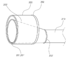
1 is an explanatory view for explaining an aeration plate and a drain pipe of a buried drainage channel in which a water collecting chamber of the present invention is formed.
FIG. 2 is a perspective view of a pouring organ of a buried drainage pipe having a water collecting chamber of the present invention.
FIG. 3 is an explanatory diagram for explaining a state in which a pouring orifice is coupled to a drain pipe of a buried drainage pipe having a water collecting chamber of the present invention.
FIG. 4 is an explanatory diagram for explaining a state in which a pouring orifice is connected to a drainage pipe of a buried drainage pipe having a water collecting chamber of the present invention, and a connection pipe is connected.
5 is a perspective view of a water collecting wall of a buried drainage channel having a water collecting chamber of the present invention.
FIG. 6 is an exploded perspective view for explaining a coupling relationship of a buried drainage pipe having a water collecting chamber of the present invention. FIG.
7 is a perspective view of a buried drainage channel having a water collecting chamber of the present invention.
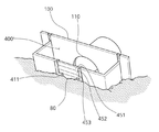
8 is an explanatory view for explaining a state of embedding a buried drainage pipe having a water collecting chamber of the present invention.
FIG. 9 is an explanatory diagram for explaining the rapid draining ability of the buried drains having the water collecting chamber of the present invention at the time of heavy rains. FIG.
FIG. 10 is an explanatory view for explaining a state where water is supplied at an appropriate time to an adjacent paddy field and a remote paddy field through a buried drainage having a water collecting chamber of the present invention.
DETAILED DESCRIPTION OF THE PREFERRED EMBODIMENTS Hereinafter, a buried drain can 1 having a water collecting chamber according to the present invention will be described in detail with reference to the accompanying drawings.
Prior to this, terms and words used in the present specification and claims should not be construed to be limited to ordinary or dictionary meanings, and the inventor should appropriately define the concept of terms in order to describe his invention in the best way. It should be construed as meaning and concept consistent with the technical idea of the present invention. Therefore, it should be understood that the embodiments described herein are merely the most preferred embodiments of the present invention and are not intended to represent all of the technical ideas of the present invention. Therefore, at the time of filing the patent application of the present invention, It should be understood that variations can be made. In the following description of the present invention, a detailed description of known functions and configurations incorporated herein will be omitted when it may make the subject matter of the present invention rather unclear. In addition, in adding reference numerals to the constituent elements of the drawings, it is to be noted that the same constituent elements are denoted by the same reference numerals even though they are shown on different drawings.
FIG. 1 is an explanatory view for explaining an aeration plate and a drainage pipe of a buried drainage channel in which a water collecting chamber of the present invention is formed, FIG. 2 is a perspective view of a drainage channel of a buried drainage channel having a water collecting chamber of the present invention, FIG. 3 is an explanatory view for explaining a state in which a pouring orifice is coupled to a drainage pipe of a buried drainage channel having a water collecting chamber of the present invention, and FIG. 4 is a cross- FIG. 5 is a perspective view of a water collecting wall of a buried drainage pipe having a water collecting chamber according to the present invention, and FIG. 6 is a perspective view of a buried drain And FIG. 7 is a perspective view of a buried drainage pipe having a water collecting chamber of the present invention.
As shown in Figs. 1 to 7, the buried
This will be described in more detail below.
Considering the rural realities in Korea, the
Fig. 1 is a view showing that a
As shown in Fig. 1, the
A central portion of the
T-shaped attachment and
For the sake of convenience, the T-type
A lower end point of the T-shaped attachment /
The plurality of T-shaped
The outer surface of the
The
A
3 is an explanatory view for explaining a state in which a laying tube 200 'is coupled to a
As shown in FIGS. 2 to 4, the funnel pipe 200 'described below may be coupled to the
A coupling groove 201 'is formed in a central lower portion of the outer periphery of the funnel pipe 200' in the longitudinal direction corresponding to the
That is, in the adjacent paddy field, a
At this time, the water supply amount per unit time for remote discussion is determined according to the size of the injection port of the funnel pipe 200 'as shown in FIG. Therefore, it is preferable that the funnel pipe 200 'has various diameters of the injection ports. Usually, large, medium, small three is good.
3, the ratio of the excess space in which the funnel pipe 200 'is inserted to the
That is, in order to increase the injection quantity per unit time in the remote place, the funnel pipe 200 'having a large opening at the inlet of the funnel pipe 200' may be used. To reduce the injection amount per unit time at the remote place, The funnel pipe 200 'having a narrow inlet port is used.
At this time, if the funnel pipe 200 'is short, the
At this time, a
Of course, the coupling frames 202 'and 212 are formed to protrude from the outer periphery of the other end of the funnel pipe 200' or the
5 is a perspective view of the
5, the
First, the
The
The water level regulating
The
A
A
The
A
The
A bottom wall 440 bent from the lower end of the
It is preferable that the bottom wall 440 is provided with a plurality of
That is, the
At this time, since the lowermost end of the water
Next, the operation of the buried
First, a
T-shaped attachment /
The
If necessary, the
In addition, a water level control door 411 (not shown) is formed by a rectangular panel having a width of 40 x 25 cm and a width of 40 cm and a width of 40 cm, A water level adjusting
The T-shaped
The buried
The number of burials may vary depending on the length of the rice paddies, but usually 2 to 5 paddies are buried in each rice paddy.
8, the bottom of the water
That is, the lowermost end of the water
By removing the
The T-type
According to the water collecting chamber 400 'formed as described above, water can be supplied to the rice paddies only when the water level of the rice reaches a certain water level.
In other words, if the water level control panel (451, 452, 453) is inserted until the water level reaches the top of the water collecting chamber, the water level of the water level will be high and the water level control panel is selected from 451 to 453, If it is stored in the control
On the other hand, when the water
9 and 10, if the water
Although the present invention has been described in detail with respect to the construction and operation of the buried
1 burial drainage forming a house
100
200
200 'shoveling engine 201' coupling groove 202 '
210 connector 211 coupling groove 212 coupling groove
300
400 house water wall 400 'house room
410
420 Left side wall 421 T-type
430 Right side wall 431 T-type mounting rail
440
Claims (9)
A drain pipe 200 formed to be cut at a length not longer than the width of the rice puddle to maintain watertightness in the drain hole 110 on the outer surface of the water level plate 100 and to have one end integrally formed with the drain hole 110 of the water level plate 100, and;
A hose (300) connected to the coupling frame (202) of the drain pipe (200) for watering the lower rice field;
The water level control door 411 is formed by a rectangular flat panel having a width of 40 x 25 cm and a width of 10 cm and a depth of 9 cm at the center of the upper part. A water level adjusting plate inserting groove 412 is formed on both sides of the water level adjusting door 411 and a water dropping door 413 having a depth of 7 cm and a depth of 4 cm is formed in a lower central region of the water level adjusting door 411, A front side wall 410 having a water drop insertion groove 414 formed on both sides of the water drop door 413 and a front side wall 410 formed bending from the left side end of the front side wall 410 and having a T type detachable rail 421 A left side wall 420 and a right side wall 430 bent from the right side end of the front side wall 410 and having a T type detachable rail 431 formed at an end thereof, And a bottom wall 444 formed by contacting the lower end of the seating wall 420 and the lower wall of the wall 434, 0) is formed integrally with the water collecting wall 400,
The T-shaped attaching / detaching rails 421 and 431 of the water collecting wall 400 are slidably inserted into and connected to the respective T-shaped detachable grooves 120 of the water distributor plate 100, Characterized in that the water wall (400) forms a water collecting chamber (400 ').
Priority Applications (1)
| Application Number | Priority Date | Filing Date | Title |
|---|---|---|---|
| KR20130106024A KR20150027537A (en) | 2013-09-04 | 2013-09-04 | An irrigation gate for a rice field |
Applications Claiming Priority (1)
| Application Number | Priority Date | Filing Date | Title |
|---|---|---|---|
| KR20130106024A KR20150027537A (en) | 2013-09-04 | 2013-09-04 | An irrigation gate for a rice field |
Publications (1)
| Publication Number | Publication Date |
|---|---|
| KR20150027537A true KR20150027537A (en) | 2015-03-12 |
Family
ID=53022851
Family Applications (1)
| Application Number | Title | Priority Date | Filing Date |
|---|---|---|---|
| KR20130106024A KR20150027537A (en) | 2013-09-04 | 2013-09-04 | An irrigation gate for a rice field |
Country Status (1)
| Country | Link |
|---|---|
| KR (1) | KR20150027537A (en) |
Cited By (3)
| Publication number | Priority date | Publication date | Assignee | Title |
|---|---|---|---|---|
| CN106702981A (en) * | 2016-12-22 | 2017-05-24 | 中国水利水电科学研究院 | Parameter generation method and device of irrigated area drainage system |
| KR20170002655U (en) | 2016-01-15 | 2017-07-25 | 강성원 | Inlet for irrigation |
| KR102624976B1 (en) * | 2023-05-16 | 2024-01-15 | 굿비비 주식회사 | Angle-adjustable watering apparatus |
-
2013
- 2013-09-04 KR KR20130106024A patent/KR20150027537A/en not_active Application Discontinuation
Cited By (3)
| Publication number | Priority date | Publication date | Assignee | Title |
|---|---|---|---|---|
| KR20170002655U (en) | 2016-01-15 | 2017-07-25 | 강성원 | Inlet for irrigation |
| CN106702981A (en) * | 2016-12-22 | 2017-05-24 | 中国水利水电科学研究院 | Parameter generation method and device of irrigated area drainage system |
| KR102624976B1 (en) * | 2023-05-16 | 2024-01-15 | 굿비비 주식회사 | Angle-adjustable watering apparatus |
Similar Documents
| Publication | Publication Date | Title |
|---|---|---|
| US3408818A (en) | Capillary subterranean irrigation system | |
| US20220142065A1 (en) | Liquid Containment and Focus for Subterranean Capillary Irrigation | |
| CN106088305A (en) | Greenery patches and construction method thereof with underground conservation pool | |
| US8256989B2 (en) | Water-storage and water-purification system | |
| KR101215777B1 (en) | Underground watering·draining system | |
| KR20150027537A (en) | An irrigation gate for a rice field | |
| KR101036257B1 (en) | Protected device for ridge | |
| CN106688702A (en) | Harmless greenhouse system and greenhouse planting method | |
| CN109328783A (en) | A kind of seedbed and preparation method thereof suitable for Light media cup | |
| JP5970675B2 (en) | Underground irrigation system | |
| CN205266517U (en) | Automatic drainage system that irrigates in flower nursery | |
| DE102017114887B4 (en) | Building area planting system and cultivating pot for plants | |
| JP2015223177A (en) | Water-retaining planter | |
| US2210218A (en) | Soil conservation apparatus | |
| Ferguson | Subsurface drip irrigation for turf | |
| JPH0824497B2 (en) | Irrigation / drainage system | |
| KR101459654B1 (en) | Eco-friendly aqueduct structure | |
| JP2010029072A (en) | Subirrigation system | |
| CN218681323U (en) | Ecological structure terraced fields that breed combines | |
| CN210421005U (en) | Ecological revetment beneficial to water circulation | |
| JP5755132B2 (en) | Isolation floor cultivation facility and unit for isolation floor cultivation facility constituting the facility | |
| WO2022114098A1 (en) | Cultivation system and cultivation method for water-grown wasabi | |
| Kemper et al. | Economics of alternatives for managing intense rainfall on agricultural watersheds | |
| JP3066038B2 (en) | Integrated water supply and drainage function device | |
| CN205213651U (en) | Underground percolation watering facility |
Legal Events
| Date | Code | Title | Description |
|---|---|---|---|
| A201 | Request for examination | ||
| E902 | Notification of reason for refusal | ||
| E601 | Decision to refuse application |