KR20150004860A - Apparatus and process for surface gasification in a reduction reactor shaft - Google Patents
Apparatus and process for surface gasification in a reduction reactor shaft Download PDFInfo
- Publication number
- KR20150004860A KR20150004860A KR20147032326A KR20147032326A KR20150004860A KR 20150004860 A KR20150004860 A KR 20150004860A KR 20147032326 A KR20147032326 A KR 20147032326A KR 20147032326 A KR20147032326 A KR 20147032326A KR 20150004860 A KR20150004860 A KR 20150004860A
- Authority
- KR
- South Korea
- Prior art keywords
- reducing gas
- reaction furnace
- channel body
- reduction reaction
- reducing
- Prior art date
Links
Images


Classifications
-
- C—CHEMISTRY; METALLURGY
- C21—METALLURGY OF IRON
- C21B—MANUFACTURE OF IRON OR STEEL
- C21B13/00—Making spongy iron or liquid steel, by direct processes
- C21B13/02—Making spongy iron or liquid steel, by direct processes in shaft furnaces
-
- F—MECHANICAL ENGINEERING; LIGHTING; HEATING; WEAPONS; BLASTING
- F27—FURNACES; KILNS; OVENS; RETORTS
- F27B—FURNACES, KILNS, OVENS, OR RETORTS IN GENERAL; OPEN SINTERING OR LIKE APPARATUS
- F27B15/00—Fluidised-bed furnaces; Other furnaces using or treating finely-divided materials in dispersion
- F27B15/006—Equipment for treating dispersed material falling under gravity with ascending gases
-
- F—MECHANICAL ENGINEERING; LIGHTING; HEATING; WEAPONS; BLASTING
- F27—FURNACES; KILNS; OVENS; RETORTS
- F27B—FURNACES, KILNS, OVENS, OR RETORTS IN GENERAL; OPEN SINTERING OR LIKE APPARATUS
- F27B15/00—Fluidised-bed furnaces; Other furnaces using or treating finely-divided materials in dispersion
- F27B15/02—Details, accessories, or equipment peculiar to furnaces of these types
- F27B15/10—Arrangements of air or gas supply devices
Landscapes
- Engineering & Computer Science (AREA)
- Chemical & Material Sciences (AREA)
- Dispersion Chemistry (AREA)
- Mechanical Engineering (AREA)
- General Engineering & Computer Science (AREA)
- Materials Engineering (AREA)
- Manufacturing & Machinery (AREA)
- Metallurgy (AREA)
- Organic Chemistry (AREA)
- Manufacture Of Iron (AREA)
- Devices And Processes Conducted In The Presence Of Fluids And Solid Particles (AREA)
- Physical Or Chemical Processes And Apparatus (AREA)
- Organic Low-Molecular-Weight Compounds And Preparation Thereof (AREA)
- Furnace Charging Or Discharging (AREA)
Abstract
본 발명은 환원 가스를 사용하여 분광 형태인 금속 산화물을 함유하는 재료로부터 스펀지 메탈 또는 선철을 제조하는 장치에 관한 것으로서, 환원 반응 노(1) 및 환원 반응 노(1)의 내부로 환원 가스를 도입하기 위해 환원 반응 노(1)의 내부에서 종결되는 여러 개의 환원 가스 입구 라인들을 포함한다. 상기 장치는 환원 반응 노(1)의 내부로 환원 가스를 분배하기 위해 환원 반응 노(1)의 내부를 통해 통과하는 환원 가스 채널 본체(11)가 제공되는 것을 특징으로 하며, 환원 가스 채널 본체(11)의 하나 이상의 내벽 단부 상에서, 본질적으로 환원 가스 채널 본체(11) 아래의 수직으로, 환원 반응 노(1)의 내부의 환원 가스 채널 본체 아래에 환원 가스를 공급하기 위한 하나 이상의 환원 가스 공급 라인이 제공되며, 환원 가스 채널 본체(11)가 캐리어 튜브를 가지며 상기 캐리어 튜브를 통해 냉각 매체가 유동할 수 있다. 본 발명에 따라서, 환원 가스의 제 1 부분 양이 환원 반응 노의 내부에서 종결되는 여러 개의 환원 가스 입구 라인들에 의해서 층으로 도입되며, 환원 가스의 제 2 부분 양은 환원 반응 노의 내부를 통과하는 환원 가스 채널 본체에 의해서 층 내부로 분배된다. 환원 가스의 제 2 부분 양은 환원 반응 노의 내부의 환원 가스 채널 본체의 본질적으로 수직 아래로 공급된다.The present invention relates to an apparatus for producing sponge metal or pig iron from a material containing a metal oxide which is in a spectroscopic form using a reducing gas and is characterized in that a reducing gas is introduced into the reduction reaction furnace 1 and the reduction reaction furnace 1 And a plurality of reducing gas inlet lines terminating inside the reduction reaction furnace 1 for the sake of simplicity. Characterized in that the apparatus is provided with a reducing gas channel body (11) passing through the interior of a reduction reaction furnace (1) for distributing a reducing gas to the interior of a reduction reaction furnace (1) (1) for supplying a reducing gas under the reducing gas channel body inside the reducing reaction furnace (1), essentially vertically below the reducing gas channel body (11), on at least one inner wall edge of the reducing gas channel body And the reducing gas channel body 11 has a carrier tube and the cooling medium can flow through the carrier tube. According to the present invention, a first portion of the reducing gas is introduced into the bed by a plurality of reducing gas inlet lines terminating in a reduction reaction furnace, the second portion of the reducing gas passing through the interior of the reducing reaction furnace And is distributed inside the layer by the reducing gas channel body. The second amount of reducing gas is fed essentially vertically below the reducing gas channel body inside the reduction reaction furnace.
Description
본 발명은 환원 가스(reduction gas)를 이용하여 금속 산화물을 함유하는 분광(piece)들의 형태인 재료로부터 메탈 스폰지(metal sponge) 또는 선철(pig iron)을 제조하는 장치에 관한 것으로, 이 장치는 환원 반응 노 및 이 환원 반응 노의 내부로 환원 가스를 도입하기 위해 환원 반응 노의 내부에서 끝나는 다수의 환원 가스 입구 라인(inlet line)들을 포함한다.
The present invention relates to an apparatus for producing a metal sponge or pig iron from a material in the form of a piece containing metal oxides using a reduction gas, And a plurality of reducing gas inlet lines ending inside the reduction reaction furnace to introduce a reducing gas into the reaction furnace.
환원로(reduction shaft) 내에서 층(bed)으로서 존재하는 산화 철을 함유하는 재료를 환원 가스에 의해 변환(conversion)함으로써 해면 철(sponge iron)을 제조할 때, 환원 가스는 환원로의 -대부분 완전히-원주 주위에서 링 형상으로 이어진 소위, 버슬 파이프(bustle pipe)-또한 쇼트(short)용 버슬로서 지칭됨-를 통해 본질적으로 환원로 내로 대부분 도입되며, 이 파이프는 산화 철을 함유하는 재료가 충전된(filled) 환원로의 내부에서 소위, 버슬 슬롯(bustle slot)들에 연결된다. 이 버슬은 환원로의 내화 외벽(fireproof outer walling)-소위, 내부 버슬-내에 또는 환원로 외부-소위, 외부 버슬-에 배치될 수 있다. 환원로의 내화 외벽의 내부 버슬로부터 나오거나 외부 버슬에 연결되는 개구들-버슬 슬롯들-을 통해, 환원 가스가 버슬로부터 환원로 내로 분배된다. 통상적으로, 버슬은 환원로의 전체 원주 주위에 이어지며, 유사하게 버슬 슬롯들은 전체 원주 주위에 배치되는데, 이는 균등한(even) 환원을 얻기 위해서 환원 가스가 균등하게 분배된 채로 도입되어야 하기 때문이다.
When producing a sponge iron by converting a material containing iron oxide present as a bed in a reduction shaft by a reducing gas, Called bustle pipe, also referred to as a short for short, which is connected in a ring around the circumference of the circumference, is essentially introduced into the reduction furnace, Called " bustle " slots in the filled return path. This variant can be placed in a fireproof outer walling of the reducing furnace - a so-called inner bath - or on the outside of the re-furnace - the so called outer bath. Reduced gas is distributed from the bees into the reduction furnace through openings-burse slots-either from the inner bead of the refractory outer wall of the reduction furnace or connected to the outer bead. Typically, the bead extends around the entire circumference of the reduction furnace, and similarly the burse slots are disposed around the entire circumference, since the reducing gas must be introduced in an evenly distributed manner to obtain even reduction .
환원 가스는 일반적으로, 환원로가 작동 중일 때 대체로 층에 의해 충전된 내부 영역 내로 버슬 슬롯들이 나타나지 않도록, 분배되고 도입된다. 예컨대, 환원로는, 종종 환원로의 축을 따라 위에서부터 수직방향으로 볼 때 환원로의 내부 공간의 직경이 급격하게 확대하도록(jump in the expansion) 제조되며, 내경은, 이러한 확대가 예컨대, 내화 외부 벽의 두께를 변화시킴으로써 실현될 수 있도록, 내화 외벽에 의해 결정된다. 산화 철을 함유하는 재료의 층 각도(bed angle)의 결과로서, 층이 충전되지 않은 링 형상 영역이 전체 원주 주위에서 확대부(또한, 리턴(return)이라 부름)에 형성된다. 이후, 버슬 슬롯들이 링 형상 영역 내에 나타난다.
The reducing gas is generally dispensed and introduced so that the burse slots do not appear in the interior region, which is generally filled by the layer when the reducing furnace is in operation. For example, the reduction furnace is often manufactured such that the diameter of the inner space of the reduction furnace is sharply enlarged as viewed from above in the vertical direction along the axis of the reduction furnace, and the inside diameter is, for example, Is determined by the refractory outer wall so that it can be realized by changing the thickness of the wall. As a result of the bed angle of the material containing the iron oxide, a ring-shaped region in which the layer is not filled is formed around the entire circumference at an enlargement (also called a return). Then, the bezel slots appear in the ring-shaped area.
환원 가스는 그와 함께 분진(dust)을 가지며, 이 분진이 환원로 내로 도입된 후에 링 형상 영역에 그리고 산화 철을 함유하는 재료 층 내에 쌓인다. 이에 따라, 분진이 없는 가스에 비해 증가된 압력 강하가 환원로의 원주에서 형성되며, 여기에서 환원가스가 층의 중심을 향해 도입되며- 쌓인 분진은 층을 통과하는 환원 가스의 유동 경로(flow path)들을 차단한다. 이의 결과들 중 하나는, 층의 불균일한 가스화이며, 동반하여 불균일한 환원이 유발된다. 예컨대, COREX® 방법에서와 같이 환원로에서 환원되는 재료, 예컨대 해면 철이 용융 가스화로(melter gasifier)에 도입될 때, 차단된 유동 경로들로부터 환원로의 중심에서 저압이 발생함으로 인해, 용융 가스화로로부터 해면 철 컨베이어 라인(conveyor line)들을 통해 환원로 내로 분진이 많이 포함된 가스(heavily dust-laden gas)(이는 소망되지 않음)의 바람직하지 않은 흐름을 유발할 수 있다.
The reducing gas has dust with it and is deposited in the ring-shaped region and in the layer of material containing iron oxide after the dust is introduced into the reducing furnace. Thereby, an increased pressure drop relative to the dust-free gas is formed in the circumference of the reducing furnace, where the reducing gas is introduced towards the center of the bed, and the accumulated dust is removed from the flow path of the reducing gas ). One of the consequences of this is the uneven gasification of the layer, accompanied by non-uniform reduction. For example, when a material to be reduced in a reduction furnace, such as sea surface iron, is introduced into a melter gasifier as in the COREX 占 process, a low pressure is generated at the center of the reduction furnace from the blocked flow paths, Can cause undesirable flow of heavily dust-laden gas (which is not desired) into the reduction furnace through sponge iron conveyor lines.
환원로 내로의 환원 가스의 도입을 균일하게 하고 또한 환원로 원주에 비해 환원로의 중심에서 보다 저압의 결과로서 발생된 문제들을 회피하기 위해서, 버슬 슬롯들을 갖는 버슬에 추가하여, 환원로의 외부측으로부터 환원 가스를 도입하기 위해 버슬 아래에 배열된 반경 방향으로 이어진 추가의 채널(channel)들을 중심에 제공하는 것이 EP 0904415 B1에 제안되고 있다. 환원로는, 원주의 이러한 채널들 뿐만 아니라 환원로의 횡단면 표면을 통해 층 내로 도입된다. 이 경우의 문제점은, EP 0904415 B1에 따른 채널들이 환원로의 중심에 고가의 지지체들을 가져야만 하며, 버슬과 채널들 사이의 간격 때문에, 채널들에 대한 환원 가스가 버슬로부터 채널들 내로 지향될 수 없으며, 복수 개의 채널들이 점유하는 횡단면(cross-sectional surface) 때문에 복수 개의 채널들을 사용하면, 상방으로 이동하는 층들의 차단들이 유발될 수 있다. WO 2009000409는 버슬 없이 채널들을 통해 환원로 내로 전체 환원 가스를 도입하는 것을 제안한다. 이에 따라, 채널들은 EP 0904415 B1에서 보다 더 많은 환원 가스를 도입해야 하며 이에 대응하여 EP 0904415 B1에서 보다 더 큰 치수이어야 하기 때문에, 차단의 문제들이 악화된다. 게다가, 환원로의 횡단면으로의 가스의 공급은 버슬을 사용하는 것에 비해 훨씬 불균일하다.
In addition to the buzz with the buccal slots, it is possible to increase the amount of the reducing gas introduced into the outer side of the reducing furnace in order to uniform the introduction of the reducing gas into the reducing furnace and to avoid problems arising as a result of the lower pressure at the center of the reducing furnace, It is proposed in EP 0904415 B1 to provide a radially centered additional channel arranged below the bead in order to introduce a reducing gas therefrom. The reduction furnace is introduced into the layer through these channels of the circumference as well as the cross-sectional surface of the reduction furnace. The problem in this case is that the channels according to EP 0904415 B1 must have expensive supports at the center of the reduction furnace and that due to the spacing between the bars and channels the reducing gas for the channels can be directed into the channels from the can And the use of a plurality of channels due to the cross-sectional surface occupied by the plurality of channels may result in interception of layers moving upward. WO 2009000409 proposes introducing a full reduction gas into the reduction furnace through channels without bass. As a result, the channels have to introduce more reducing gas than in EP 0904415 B1 and correspondingly have to be larger in size than in EP 0904415 B1, so that the blocking problems are exacerbated. In addition, the supply of gas to the cross section of the reduction furnace is much more uneven than the use of a bead.
선철 제조용 고로(blast furnace) 방법이 종래 기술로부터 또한 공지되어 있으며, 이 방법에서는, 표준 버전에서 위로부터 철-함유 분광 재료들(iron-bearing pieces of material) 및 코크스(coke)가 공급되고, 하부 영역에서, 뜨거운 바람이 취입된다(blown in). 보다 최근에 개발된 것들은, 특히 고로가 기술적으로 순수 산소로 작동되며, 처리 후에 샤프트의 하부 영역에서 고로에 노 가스(furnace gas)의 일부가 추가 환원 가스로서 공급되게 한다. 유사하게, 원주 상에 버슬에 의해서만 환원 가스를 공급함으로써 고로 내에 가스 분배가 불균일해지게 된다.
A blast furnace process for making pig iron is also known from the prior art in which iron-bearing pieces of material and coke are fed from above in a standard version, In the region, hot wind is blown in. More recently developed, in particular, the blast furnace is technically operated with pure oxygen, and after processing a portion of the furnace gas in the lower region of the shaft is supplied as additional reducing gas. Similarly, by supplying the reducing gas only by the burr on the circumference, the gas distribution in the blast furnace becomes uneven.
WO 0036159 및 WO 0036157는 환원 반응 노의 내부를 통해 통과하는 파이프를 통해 환원 반응 노 내로 고온 환원 가스를 도입하는 방법을 도시하며, 이 방법은 파이프를 냉각하는 단계, 파이프를 절연시키는 단계 및 내부 내로 파이프의 벽을 통해 고가의(expensive) 환원 가스를 운반하는 단계를 구성한다.
WO 0036159 and WO 0036157 illustrate a method of introducing a hot reducing gas into a reduction reaction furnace through a pipe passing through the interior of a reduction reaction furnace, comprising the steps of cooling the pipe, insulating the pipe, And constitutes a step of transporting expensive reducing gas through the walls of the pipe.
본 발명의 목적은, 종래 기술의 문제들이 가능한 한 완전하게 회피되는, 환원 반응 노 내에서 환원 가스를 이용하여 금속 산화물을 함유하는 재료 층으로부터 스펀지 메탈 또는 선철을 제조하는 장치 및 방법을 제공하는 것이다.
It is an object of the present invention to provide an apparatus and method for producing sponge metal or pig iron from a material layer containing a metal oxide using a reducing gas in a reduction reaction furnace where problems of the prior art are avoided as completely as possible .
본 발명의 목적은, 환원 가스를 이용하여 금속 산화물을 함유하는 재료 층으로부터 스펀지 메탈 또는 선철을 제조하는 장치에 의해 달성되며, 이 장치는, 환원로, 및 환원 반응 노의 내부로 환원 가스를 도입하기 위해 환원 반응 노의 내부에서 종결되는 다수의 환원 가스 입구 라인들을 포함한다.
The object of the present invention is achieved by an apparatus for producing sponge metal or pig iron from a material layer containing a metal oxide using a reducing gas, the apparatus comprising a reducing furnace, and a reducing gas introduced into the reducing reaction furnace And a plurality of reducing gas inlet lines terminating inside the reduction reaction furnace to form the reducing gas inlet lines.
이 장치는, 환원 반응 노 사프트의 내부에 환원 가스를 분배하기 위해 환원 반응 노의 내부를 통해 통과하는 환원 가스 채널 본체가 제공되는 것을 특징으로 하며, 여기서, 환원 가스 채널 본체의 하나 이상의 내벽측 단부 상에서, 본질적으로 환원 가스 채널 본체의 수직 하부에서, 환원 가스 채널 본체 아래에 환원 가스를 공급하기 위한 하나 이상의 환원 가스 입구 라인이 환원 반응 노의 내부에 제공되며, 환원 가스 채널 본체는 냉각 매체가 이를 통해 유동할 수 있는 캐리어 튜브를 갖는다.
The apparatus is characterized in that a reducing gas channel body is provided through which the reducing gas is passed through the interior of the reduction reaction furnace to distribute the reducing gas inside the reduction reaction furnace, wherein at least one inner wall- At least one reducing gas inlet line for supplying a reducing gas below the reducing gas channel body is provided inside the reduction reaction furnace in the vertical lower portion of the reducing gas channel body, Lt; RTI ID = 0.0 > a < / RTI >
스펀지 메탈은, 바람직하게는, 해면 철(sponge iron)을 포함한다.
The sponge metal preferably comprises sponge iron.
이에 따라, 금속 산화물을 함유하는 분광들의 형태인 재료는, 바람직하게는 산화 철을 함유하는 분광들의 형태인 재료를 포함한다. 분광들의 형태인 재료는, 예컨대 소결물(sinter)의 경우 5 mm 초과, 50 mm 이하, 압분(compacting)과 같은 괴상화 방법들 이후에 100 mm 이하의 입도(grain size)를 갖는 재료; 예컨대, 괴광(lump ore), 펠릿(pellet)들 또는 소결물로서 이해된다.
Thus, the material in the form of spectra containing metal oxides preferably comprises a material in the form of spectra containing iron oxide. Materials in the form of spectroscopic materials may have a grain size of less than or equal to 100 mm after agglomeration methods such as, for example, greater than 5 mm, less than 50 mm, compacting in the case of sinter; For example, as lump ore, pellets or sintered product.
환원 반응 노는, 예컨대 COREX® 방법에서 사용되는 것과 같은 이를 테면 샤프트 리액터, 또는 고로의 상부 부분, 즉, 간접 가스 환원이 발생하는 고로의 일부로서 이해되는 것이다. 샤프트 반응로에서, 예컨대, 고상 스펀지 메탈(solid metal sponge)가 제조되는 한편, 고로에서 액상 원료 철(liquid raw iron)이 제조된다.
The reduction reaction furnace is understood, for example, as a shaft reactor, such as that used in the COREX® process, or as a part of the upper portion of the blast furnace, that is, the blast furnace where indirect gas reduction occurs. In the shaft reactor, for example, solid metal sponge is produced, while liquid raw iron is produced in the blast furnace.
환원 반응 노의 내부(interior) 내로 환원 가스를 도입하기 위하여, 환원 가스 반응로의 내부에서 종결되는 다수의 환원 가스 유입 라인들이 존재한다. 이 같은 경우들에서 내부 포뮬레이션(interior formulation)에서의 종결은 환원 가스 유입 라인들이 내부 내로 연장할 수 있는 것으로서, 그러나 또한 환원 가스 유입 라인의 단부가 내부, 예를 들면 방화 외벽의 버슬 슬롯(bustle slot)의 개방의 범위를 정하는 내벽에 놓일 수 있는 것으로 이해되어야 한다.
In order to introduce the reducing gas into the interior of the reduction reaction furnace, there are a number of reducing gas inlet lines terminating inside the reducing gas reaction furnace. In these cases, the termination in the interior formulation is such that the reducing gas inlet lines can extend into the interior, but also the end of the reducing gas inlet line is located inside, for example, bustle lt; RTI ID = 0.0 > slot. < / RTI >
환원 가스는 환원 가스 유입 라인들로부터 이러한 환원 가스 유입 라인들의 환원 가스 유출구들을 통하여 환원 반응 노로 유입되고 이때 금속 산화물을 함유하는 재료의 분광들의 층을 통하여 유동한다.
The reducing gas flows from the reducing gas inlet lines through the reducing gas outlets of the reducing gas inlet lines to the reducing reaction furnace and through the layer of the material containing the metal oxide.
더욱이, 환원 반응 노의 내부를 통과하는 환원 가스 채널 본체는 환원 가스 반응 노의 내부 내로 환원 가스의 분배를 위해 존재한다. 환원 가스 채널 본체는 할선(secant)으로서 또는 직경으로서 내부를 통과할 수 있으며, 여기서 직경으로서의 통과가 바람직한데, 이는 환원 가스가 이때 더 대칭적이고 더 균등하게 층 내로 들어갈 수 있기 때문이다. 환원 가스 채널 본체는 예를 들면 환원 가스가 층 내로 수직 높이 상에서 도입될 수 있도록 수평 방향으로 연장될 수 있다. 그러나, 환원 가스 채널 본체는 수직선들에 대해 최저점 또는 최고점을 가질 수 없어, 환원 가스 채널 본체는 환원 반응 노의 벽으로부터 환원 반응 노의 중심으로 하방 또는 상방으로 기울어지는 두 개의 부분 섹션(section)들을 갖는다. 이때 환원 가스는 작동 동안 상이한 수직 높이들에서 층으로 유입될 수 있다.
Moreover, the reducing gas channel body passing through the interior of the reduction reaction furnace exists for the distribution of the reducing gas into the interior of the reducing gas reaction furnace. The reducing gas channel body may pass through the interior as a secant or as a diameter where passage as a diameter is preferred because the reducing gas can then be more symmetric and more uniformly entering the layer at this time. The reducing gas channel body may extend in the horizontal direction, for example, so that a reducing gas can be introduced into the layer at a vertical height. However, the reducing gas channel body can not have the lowest point or peak with respect to the vertical lines, so that the reducing gas channel body has two partial sections that are inclined downward or upward from the wall of the reducing reaction furnace to the center of the reducing reaction furnace . Where the reducing gas may flow into the layer at different vertical heights during operation.
환원 가스 채널 본체는 환원 반응 노의 내벽들에 의해 경계가 정해진 환원 반응 노의 내부를 통과한다. 이때 환원 가스 채널 본체는 두 개의 내벽 측 단부들을 갖는다. 본 발명에 따라, 환원 가스 반응기 노의 내부 내로 환원 가스를 공급하기 위한 하나 이상의 환원 가스 유입 라인은 환원 가스 채널 본체의 하나 이상의 내벽 측 단부에서 환원 가스 채널 본체의 본질적으로 수직 방향 아래에 존재한다.
The reducing gas channel body passes through the inside of the reduction reaction furnace bounded by the inner walls of the reduction reaction furnace. Wherein the reducing gas channel body has two inner wall side ends. According to the present invention, one or more reducing gas inlet lines for supplying a reducing gas into the interior of the reducing gas reactor furnace are present at essentially one or more inner wall side ends of the reducing gas channel body below the essentially vertical direction of the reducing gas channel body.
환원 가스는 환원 가스 채널 본체 아래 환원 가스 반응기 노의 내부에 공급된다.
The reducing gas is supplied to the inside of the reducing gas reactor furnace under the reducing gas channel main body.
본 발명의 장치의 작동 동안 환원 반응 노 내에 위치되는 층 내의 환원 가스 채널 본체 아래에 자유 공간이 형성되는데, 이는 주로 그 층의 층 각도에 의해 결정된다. 자유 공간은 또한 환원 가스 채널로 지칭될 수 있다. 환원 가스 채널 본체는 환원 반응 노 내에 위치된 층 내의 이 같은 자유 공간 또는 환원 가스 채널의 형성을 초래하기에 적합하다. 자유 공간 또는 환원 가스 채널은 환원 반응 노의 내부 내에 환원 가스의 공급 및 분배를 위해 사용된다. 환원 가스는 환원 가스 채널 본체의 전체 길이에 걸쳐 자유 공간 내에 분배되어 층 내로 균일하게 유입될 수 있다.
During operation of the apparatus of the present invention, a free space is formed below the reducing gas channel body in the layer located in the reduction reaction furnace, which is mainly determined by the layer angle of that layer. The free space may also be referred to as a reducing gas channel. The reducing gas channel body is suitable to result in the formation of such free space or reducing gas channels in the layer located in the reduction reaction furnace. The free space or reduction gas channel is used for the supply and distribution of the reducing gas inside the reduction reaction furnace. The reducing gas can be distributed into the free space over the entire length of the reducing gas channel body and uniformly flowed into the layer.
이 경우 구 "본질적으로 수직 방향 아래(essentially vertically below)"는 환원 가스 공급 라인의 마우스(mouth)의 적어도 일 부분이 환원 가스 채널 본체의 수직방향 아래에 위치되는 것을 의미한다. 이때 작동 중 환원 가스가 환원 가스 채널 본체 아래에 형성된 자유 공간 내로 상승하고 환원 가스 채널 본체 아래의 환원 반응 노의 내부를 통과하는 이러한 자유 공간 내에 분배될 수 있을 때 이러한 입구로부터 나오는 환원 가스는 층 내로 유입될 수 있다. 이는 환원 가스가 환원 가스 채널의 전체 길이를 거쳐 환원 가스 채널로부터 층으로 유입되는 것을 가능하게 한다.
In this case, the phrase " essentially vertically below "means that at least a portion of the mouth of the reducing gas supply line is located below the vertical direction of the reducing gas channel body. When the reducing gas during operation rises into the free space formed below the reducing gas channel body and can be distributed in this free space passing through the interior of the reduction reaction furnace below the reducing gas channel body, Can be introduced. This enables the reducing gas to flow from the reducing gas channel into the bed through the entire length of the reducing gas channel.
본 발명에 따라 환원 가스 채널 본체는 냉각 매체가 통과하여 유동할 수 있는 캐리어 튜브(carrier tube)를 갖는다.
According to the present invention, the reduced gas channel body has a carrier tube through which the cooling medium can flow.
금속은 바람직하게는 환원 가스 채널 본체를 위한 그리고 상세하게는 캐리어 튜브를 위한 재료로서 사용된다.
The metal is preferably used as a material for the reducing gas channel body and in particular for the carrier tube.
캐리어 튜브는 작동 동안 요구된 기계적 특성들을 유지하기 위하여 냉각된다. 게다가, 요구된 기계적 특성들을 달성하기 위하여, 낮은 재료 온도들은 냉각되지 않은 캐리어 튜브를 구비한 것보다 더 작은 크기를 가능하게 한다. 온도를 증가시키는 것은 이와 함께 금속의 견고성(solidity)을 감소시키는데, 이는 더 높은 온도에서 특정 최소 견고성을 보장하기 위해 냉각이 존재하지 않은 경우보다 더 크게 제조되어야 한다.
The carrier tube is cooled to maintain the required mechanical properties during operation. In addition, in order to achieve the required mechanical properties, low material temperatures enable smaller sizes than with uncooled carrier tubes. Increasing the temperature also reduces the solidity of the metal, which must be made larger than when there is no cooling to ensure a certain minimum firmness at higher temperatures.
종래 기술에서, 환원 가스는 필요한 경우 냉각 매체에 의해 냉각된, 환원 반응 노의 내부를 통과하는 튜브를 통하여 환원 반응 노 내로 도입될 수 있다. 고온의 환원 가스를 공급하기 위해 이 같은 튜브가 외부 절연부를 구비하고 또한 내부 절연부(internal insulation)을 구비하게 설계되어, 저온 냉각 매체로의 고온 환원 가스의 열 방산이 매우 크지 않아야 하는데, 이는 이 같은 열 방산이 환원 가스의 불필요한 냉각을 초래하기 때문이다. 그러나 열역학적 및 운동학적 이유들 때문에 환원 가스가 특정 최소 온도로 층으로 유입되기 때문에, 이 같은 냉각을 보상하기 위하여 환원 가스는 냉각이 수행되지 않았던 경우보다 더 높은 온도로 공급되어야 한다. 더욱이 냉각 매체는 이때 매우(strongly) 더 낮게 그리고 이에 따라 냉각 매체 회로에서의 재사용을 위해 더 큰 비용으로 다시 냉각되어야 한다.
In the prior art, the reducing gas may be introduced into the reduction reaction furnace through a tube passing through the interior of the reduction reaction furnace, cooled by a cooling medium, if necessary. Such a tube is designed to have an external insulation and also to have an internal insulation so as to supply a hot reducing gas so that the heat dissipation of the hot reducing gas into the cryogenic cooling medium should not be very large, This is because the same heat dissipation causes unnecessary cooling of the reducing gas. However, because of the thermodynamic and kinematic reasons, the reducing gas must be supplied at a higher temperature than if no cooling was performed to compensate for such cooling, since the reducing gas is introduced into the layer at a certain minimum temperature. Moreover, the cooling medium must then be cooled down again at a significantly lower cost and therefore at a higher cost for reuse in the cooling medium circuit.
이 같은 공지된 구성의 방법들의 추가 단점은 내부를 통과하는 튜브에 대해 가능하지 않은 환원 가스의 단순한 단부-면-측부 배출(end-face-side exit)로 이루어진다. 튜브 내측(inside)으로부터 내부로 또는 층으로 환원 가스의 공급을 가능하게 하기 위하여, 튜브의 길이에 걸쳐 튜브의 벽을 통한 관통부(pass-through)들이 필요하다. 그러나, 이러한 관통부들은 바람직하지 않게는 튜브가 작동 동안 층의 중량을 통한 가장 큰 응력 하에 있게 되는 지점에서 튜브의 기계적 취약화를 초래한다. 게다가 가스 유동에 대한 압력 손실들은 관통부들에 의해 발생되며, 이는 특히 환원 반응 노의 중심 영역에서 가스 분배의 균일성을 감소시킨다.
A further disadvantage of the processes of this known construction is the simple end-face-side exit of the reducing gas which is not possible for the tube passing through it. Pass-through through the wall of the tube over the length of the tube is required to enable the supply of reducing gas from inside the tube to the inside or into the layer. However, such perforations undesirably result in mechanical weakening of the tube at such a point that the tube is under the greatest stress through the weight of the layer during operation. In addition, the pressure losses for the gas flow are generated by the perforations, which in particular reduces the uniformity of the gas distribution in the central region of the reduction reaction furnace.
본 발명은 환원 가스가 환원 반응 노의 내부를 통과하는 튜브에 의해 그러나 환원 반응 노의 내부 내로 환원 가스 채널 본체 아래로의 환원 가스의 공급을 위해 환원 가스 채널 본체의 본질적으로 수직방향 아래에 존재하는 환원 가스 공급 라인에 의해 환원 반응 노의 내부 내로 공급되지 않기 때문에, 이 같은 단점들을 회피한다.
The present invention relates to a process for the reduction of a reducing gas comprising the steps of reducing gas being present in the reducing gas channel body under the essentially vertical orientation of the reducing gas channel body for feeding of the reducing gas below the reducing gas channel body into the interior of the reduction reaction furnace, And is not supplied into the interior of the reduction reaction furnace by the reducing gas supply line, thereby avoiding such disadvantages.
따라서, 환원 가스 채널 본체 또는 이의 캐리어 튜브는 각각 위에서 설명된 절연부가 제공된 종래 기술의 튜브보다 더 작게 제조될 수 있는데, 이는 본 발명의 설계시 냉각이 단지 내측에 제공되고 환원 가스 공급부 및 절연부를 위한 용적이 제공되지 않아야 하기 때문이다. 환원 가스는 자유 공간 또는 환원 가스 채널을 통하여 내부 환원 반응 노 내로 분배되어, 관통부들 및 이와 관련된 단점들이 존재하지 않는다. 이러한 자유 공간 또는 환원 가스 채널은 환원 가스 채널 본체의 전체 길이에 걸쳐 연장하고, 이는 관통부들을 통한 환원 가스의 포인트-타입 공급부(point-type supply)에 비해 환원 가스의 더 균일한 분배를 초래한다.
Thus, the reducing gas channel body or its carrier tube can be made smaller than the prior art tubes provided with the insulation described above, respectively, because the cooling in the design of the present invention is only provided inside and the reducing gas supply part and the insulating part The volume should not be provided. The reducing gas is distributed into the internal reduction reaction furnace through the free space or the reducing gas channel, and there are no penetrations and associated disadvantages. This free space or reducing gas channel extends over the entire length of the reducing gas channel body, which results in a more uniform distribution of the reducing gas compared to the point-type supply of reducing gas through the perforations .
환원 가스 채널 본체는 환원 반응 노 내에 위치된 층 내의 자유 공간 또는 환원 가스 채널을 형성하기에 적합하다.
The reducing gas channel body is suitable for forming a free space or reducing gas channel in the layer located in the reduction reaction furnace.
환원 가스 채널 본체는 예를 들면 하방으로 연장되고 바람직하게는 본질적으로 평행한 벽들을 구비한 저부에서 개방된 하프 튜브 셀(half tube shell)로서 설계될 수 있고, 상기 하프 튜브 셀은 캐리어 튜브 상에 놓인다.
The reducing gas channel body may be designed, for example, as a half tube shell open at the bottom with walls extending downwardly and preferably essentially parallel, and the half tube cell is placed on the carrier tube Is set.
캐리어 튜브 상에 하프 튜브 셀들을 구비한 실시예의 형태 대신, 2개의 웨브 플레이트(web plate)들은 캐리어 튜브의 양 측부들 상에 체결, 예를 들면 용접될 수 있어, 층 내 캐리어 튜브 아래 자유 공간을 유사하게 보장한다.
Instead of the form of an embodiment with half tube cells on a carrier tube, two web plates can be fastened, e.g. welded, on both sides of the carrier tube to form a free space below the carrier tube in the layer Similar guarantees.
환원 가스 채널 본체는 캐리어 튜브 본체를 가지며 이 캐리어 튜브 본체를 통하여 냉각 매체가 유동할 수 있다. 이를 위해 캐리어 튜브는 그 내측에 냉각 매체 채널들을 가지며 이 냉각 매체 채널들을 통하여 냉각 매체가 유동할 수 있다. 캐리어 튜브는 환원 반응 노의 외벽(재킷(jacket))에 맞닿아 놓이는 양 측부들 상에 지지된다.
The reducing gas channel body has a carrier tube body through which the cooling medium can flow. To this end, the carrier tube has cooling medium channels therein, through which the cooling medium may flow. The carrier tube is supported on both sides abutting against the outer wall (jacket) of the reduction reaction furnace.
냉각 매체는 예를 들면, 환원 가스 채널 본체 또는 이의 캐리어 튜브가 상기 환원 반응 노의 재킷에 맞닿아 놓이는 지점에서 공급되고 제거된다.
The cooling medium is fed and removed, for example, at the point where the reduced gas channel body or its carrier tube abuts the jacket of the reduction reaction furnace.
물이 바람직하게는 냉각 매체로서 사용된다.
Water is preferably used as the cooling medium.
실시예의 바람직한 형태에 따라 환원 반응 노의 내부 내로의 환원 가스의 공급을 위한 환원 가스 공급 라인은 상기 환원 가스 채널 본체의 본질적으로 수직 방향 아래에 환원 가스 채널 본체의 양 내벽 측 단부들 상에 존재한다. 이는 환원 가스 채널 본체 또는 환원 가스 채널 각각에 더 균일한 공급을 위해 이루어지며, 이는 양 단부들로부터 공급되기 때문이다.
According to a preferred form of embodiment, a reducing gas supply line for the supply of reducing gas into the interior of the reduction reaction furnace is present on both inner wall side ends of the reducing gas channel body below the essentially vertical direction of the reducing gas channel body . This is done for a more uniform supply to each of the reducing gas channel body or the reducing gas channel, since it is supplied from both ends.
층으로의 환원 가스의 더욱 균일한 유입에 의해, 환원 가스와 함께 운반되는 분진은 또한 층에 더욱 균일하게 유입될 것이라고 말하는 것이 기본적으로 사실이다. 이는 환원 가스에 대한 유동 경로들의 더 적은 차단들의 발생을 유도하고 이와 연관된 문제들이 회피되는 것을 유도한다.
It is basically true that by a more uniform inflow of the reducing gas into the layer, the dust carried with the reducing gas will also flow more uniformly into the layer. This leads to the occurrence of less interruptions of the flow paths to the reducing gas and the associated problems to be avoided.
바람직하게는 환원 반응 노의 내부에 놓이는 환원 가스 입구 라인들의 환원 가스 출구들은 모두, 수직으로 볼 때 환원 반응 노의 직경의 최대 100%의 두께를 갖는 환원 반응 노의 수직 길이방향 범위의 섹션 내에 놓인다. 바람직하게는 섹션의 두께는 환원 반응 노의 직경의 최대 40%, 특히 바람직하게는 환원기 반응기 샤프트의 직경의 최대 30%, 아주 특히 바람직하게는 환원 반응 노의 직경의 최대 20%이다. 섹션의 두께가 더 작을수록, 모든 환원 가스 라인들에 하나의 소스로부터 환원 가스를 공급하는 것이 더 쉽다.
The reducing gas outlets of the reducing gas inlet lines, which are preferably located inside the reducing reaction furnace, are all located within a section of the vertical reaction zone of the reduction reaction furnace having a thickness of at most 100% of the diameter of the reduction reaction furnace as viewed vertically . Preferably the thickness of the section is at most 40% of the diameter of the reduction reaction furnace, particularly preferably at most 30% of the diameter of the reducer reactor shaft, very particularly preferably at most 20% of the diameter of the reduction reaction furnace. The smaller the thickness of the section, the easier it is to supply the reducing gas from one source to all of the reducing gas lines.
실시예의 형태에 따르면 환원 가스 입구 라인들은 버슬 슬롯(bustle slot)들의 형태로 구현된다.
According to an aspect of the embodiment, the reducing gas inlet lines are implemented in the form of bustle slots.
실시예의 다른 형태에 따르면 환원 가스 입구 라인들은 하방으로 연장된, 바람직하게는 본질적으로는 평행한, 벽들을 구비한 바닥이 개방된 절반의 튜브 쉘들로서 구현되고, 이러한 하프 튜브 쉘들은 캐리어 튜브들에 대항하여 놓인다. 캐리어 튜브들은 바람직하게는 이들 내부에 냉각 매질 채널들을 갖는다. 하프 튜브 쉘들에서 환원 반응 노의 내부에 놓이는 하프 튜브 쉘의 단부에는 하방으로 연장되는 벽들을 연결하는 횡단 벽이 제공된다. 캐리어 튜브들은 환원 반응 노의 에지로부터 환원 반응 노의 내부 안으로, 바람직하게는 방사상으로 연장한다. 환원 반응 노의 내부에 놓이는 이들의 단부에서, 튜브들은 지지되지 않으며, 즉 이들은 소위 플라잉 튜브(flying tube)들로서 구현된다.
According to another aspect of the embodiment, the reducing gas inlet lines are embodied as bottom open half shells extending downwardly, preferably essentially parallel, with walls, Against each other. The carrier tubes preferably have cooling medium channels therein. At the end of the half tube shell which is placed in the interior of the reduction reaction furnace in the half tube shells is provided a transverse wall connecting the downwardly extending walls. The carrier tubes extend from the edge of the reduction reaction furnace into the interior of the reduction reaction furnace, preferably radially. At the ends of these which lie inside the reduction reaction furnace, the tubes are not supported, i.e. they are embodied as so-called flying tubes.
실시예의 형태에 따르면 복수의 환원 가스 입구 라인들이 내부 버슬로부터 나오고, 즉 이 환원 가스 입구 라인들은 내부 버슬의 버슬 슬롯들이다.
According to an aspect of the embodiment, a plurality of reducing gas inlet lines exit the inner bath, that is, the reducing gas inlet lines are the bathtub slots of the inner bath.
모든 환원 가스 입구 라인들은 또한 내부 버슬의 버슬 슬롯들일 수 있다. 환원 가스 입구 라인들의 개수(X)에 대하여, 내부 버슬의 버슬 슬롯들인 환원 가스 입구 라인들의 개수(A)는 X 미만이거나 같고, 즉 A ≤ X 이다.
All reduction gas inlet lines may also be the bezel slots of the inner bezel. For the number X of reducing gas inlet lines, the number A of reducing gas inlet lines, which are the shoulder slots of the inner vessel, is less than or equal to X, i.e., A? X.
외부 버슬과 비교하면, 내부 버슬은 환원 반응 노의 압력 컨테이너의 덜 복잡한 실시예를 요구하며, 환원 가스의 덜 복잡한 공급을 허용한다. 게다가 더욱 많은 수의 버슬 슬롯들이 외부 버슬과 비교할 때 실현될 수 있다.
Compared with the outer bezel, the inner bezel requires a less complex embodiment of the pressure vessel of the reduction reaction furnace and allows a less complex supply of reducing gas. In addition, a greater number of buzz slots can be realized compared to the external buzz.
실시예의 다른 형태에 따르면 적어도 복수의 환원 가스 입구 라인들이 외부 버슬로부터 나오고, 즉 환원 가스 입구 라인들은 외부 버슬의 버슬 슬롯들이다. 모든 환원 가스 입구 라인들은 또한 외부 버슬의 버슬 슬롯들일 수 있다. 환원 가스 입구 라인들의 개수(X)에 대하여, 외부 버슬의 버슬 슬롯들인 환원 가스 입구 라인들의 개수(B)는 X 미만이거나 같고, 즉 B ≤ X 이다.
According to another aspect of the embodiment, at least a plurality of reducing gas inlet lines exit from the outer bath, i.e., the reducing gas inlet lines are the bathtub slots of the outer bath. All reduction gas inlet lines may also be the bezel slots of the outer bezel. For the number of reduction gas inlet lines (X), the number of reduction gas inlet lines (B), which are the buzzard slots of the external buzzle, is less than or equal to X, i.e. B? X.
내부 버슬과 비교하면, 외부 버슬은 버슬 슬롯들이 외측으로부터 더 쉽게 세정될 수 있고 환원 반응 노 내측의 내화성 외부 벽은 덜 복잡한 방식으로 실현될 수 있다.
Compared with the inner vest, the outer vest can be more easily cleaned from the outside of the buckle slots and the refractory outer wall inside the reduction reaction furnace can be realized in a less complex manner.
바람직하게는, 구체적으로 분진이 가득한(dust-laden) 환원 가스가 사용되는 경우에, 버슬 슬롯들은 서두에 설명된 것과 같이 환원로의 작업 동안 층에 의해 채워지지 않는 내부의 구역으로 개방된다. 이는 예컨대, 환원로의 길이방향 축선을 따라 위로부터 수직으로 볼 때, 그 내부의 직경의 확대부 내에 점프(jump)를 구비하여 제작되는 환원로에 의해 달성된다.
Preferably, particularly when a dust-laden reducing gas is used, the burls slots are opened to an internal zone which is not filled by the layer during operation of the reducing furnace, as described in the opening paragraph. This is achieved, for example, by a reduction furnace which is manufactured with a jump in the enlarged portion of the inside diameter thereof when viewed vertically from above along the longitudinal axis of the reduction furnace.
실시예의 다른 형태에 따르면 복수의 환원 가스 입구 라인들은 플라잉 튜브들이다. 이는 모든 환원 가스 입구 라인들이 플라잉 튜브들이 아닌 것을 의미한다. 환원 가스 입구 라인들의 개수(X)에 대하여, 플라잉 튜브들인 환원 가스 입구 라인들의 개수(C)는 X 미만이며, 또한 C < X 이다.
According to another aspect of the embodiment, the plurality of reducing gas inlet lines are flying tubes. This means that all the reducing gas inlet lines are not flying tubes. For the number X of reducing gas inlet lines, the number C of reducing gas inlet lines, which are flying tubes, is less than X and C < X.
바람직하게는, A < X 일 때, 내부 버슬의 버슬 슬롯이 아닌 환원 가스 입구 라인들 중 하나 이상은 플라잉 튜브이고; 아주 특히 바람직하게는 모두가 플라잉 튜브이며, 즉 X - A = C 이다. 바람직하게는, B < X 일 때, 외부 버슬의 버슬 슬롯이 아닌 환원 가스 입구 라인들 중 하나 이상은 플라잉 튜브이고; 아주 특히 바람직하게는 모두가 플라잉 튜브이며, 즉 X - B = C 이다. 버슬 슬롯들과 플라잉 튜브들의 조합에 의해, 환원 가스는 환원 반응 노의 내부 벽으로부터 상이한 거리들로 유입될 수 있고, 이는 유입의 안정을 유도하고 따라서 더 양호한 환원 결과를 유도한다. 단부와 단부가 연결된(end-to-end) 환원 가스 본체와 비교하면 플라잉 튜브들이 설치가 더 쉽고 더 양호한 대체 가능성을 허용하며, 동시에 이들은 단지 버슬들만을 구비한 환원 반응 노와 비교하여 환원 가스의 더욱 균일한 분배와 관련된 이득을 초래한다.
Preferably, when A < X, at least one of the reducing gas inlet lines that is not the buzz slot of the inner vessel is a flying tube; Very particularly preferably all are flying tubes, i.e. X - A = C. Preferably, when B < X, at least one of the reducing gas inlet lines that is not the buzz slot of the outer bead is a flying tube; Very particularly preferably all are flying tubes, i.e. X - B = C. By the combination of the burls slots and the flying tubes, the reducing gas can be introduced at different distances from the inner wall of the reduction reaction furnace, which leads to stabilization of the influx and thus leads to better reduction results. Compared to an end-to-end reducing gas body, the flying tubes are easier to install and allow for better alternative possibilities, while at the same time they allow the reduction of the reducing gas Resulting in a gain associated with uniform distribution.
실시예의 형태에 따르면, 환원 가스 공급 라인은 내부 버슬로부터 비롯된다. 이는 그 후 예컨대 - 가능하게는 이 과업을 위해 구체적으로 실현된 - 내부 버슬의 버슬 슬롯이거나, 이는 이러한 내부 버슬의 부분 섹션이다. 환원 가스 채널 본체의 내부 벽 측면 단부들 모두에, 환원 가스 채널 본체의 본질적으로 수직으로 아래에 존재하는 환원 가스 샤프트의 내부로의 환원 가스의 공급을 위해 환원 가스 공급 라인이 있는 것이 바람직하며; 그 후 2개의 환원 가스 공급 라인들이 존재할 수 있고, 이는 예컨대 내부 버슬의 2개의 부분 섹션들이다.
According to an aspect of the embodiment, the reducing gas supply line originates from an internal bead. This is then, for example, the bezel slot of the inner bevel, which is specifically realized for this task, possibly, or it is a partial section of this inner bevel. It is preferred that at all of the inner wall lateral edges of the reduced gas channel body there is a reducing gas feed line for the supply of the reducing gas into the interior of the reducing gas shaft existing essentially vertically below the reducing gas channel body; There may then be two reducing gas supply lines, which are for example two partial sections of the inner vessel.
실시예의 다른 형태에 따르면 환원 가스 공급 라인은 환원 반응 노 외측, 예컨대 외부 버슬로부터 비롯된다. 이는 그 후 예컨대 - 가능하게는 이러한 과업을 위해 구체적으로 실현된 - 외부 버슬의 버슬 슬롯이다.
According to another aspect of the embodiment, the reducing gas supply line originates from the outside of the reduction reaction furnace, for example, the outer bath. This is then the beast slot of the external beast, for example - possibly realized specifically for this task.
실시예의 바람직한 형태에 따르면 환원 가스 채널 본체 아래의 환원 가스의 공급을 위한 환원 가스 공급 라인 및 적어도 약간의, 바람직하게는 모든 환원 가스 입구 라인들에 동일한 내부 및/또는 외부 버슬로부터 환원 가스가 공급된다.
According to a preferred form of embodiment, a reducing gas is supplied from the same inner and / or outer gas to a reducing gas supply line for supplying a reducing gas below the reducing gas channel body and to at least some, preferably all, reducing gas inlet lines .
이는 서로 별개로 제공되는 공급부들에 대하여 필수적일 것인 구조적 경비를 감소시킨다.
This reduces the structural costs which would be necessary for the supply parts which are provided separately from each other.
실시예의 바람직한 형태에 따르면 환원 가스 채널 본체는, 환원 가스 입구 라인들의 환원 가스 출구들이 놓이는, 수직으로 볼 때 환원 반응 노의 직경의 최대 100%, 바람직하게는 최대 40%, 특히 바람직하게는 최대 30%, 아주 특히 바람직하게는 최대 20%의 두께를 갖는 적어도 부분적으로는 환원 반응 노의 수직 길이방향 범위의 섹션 내에 놓인다. 이러한 방식으로 환원 가스는 환원 가스 출구들로부터 환원 가스 채널 본체로 쉽게 운반될 수 있거나, 또는 환원 가스를 공급하는 환원 가스용 소스로부터 환원 가스 입구 라인들을 통해 환원 가스 채널 본체로 쉽게 전달될 수 있다.
According to a preferred form of embodiment, the reducing gas channel body has a diameter of at most 100%, preferably at most 40%, particularly preferably at most 30% of the diameter of the reduction reaction furnace as viewed vertically, in which the reducing gas outlets of the reducing gas inlet lines lie, %, Very particularly preferably at most 20% of the thickness of the at least partially reduced reaction furnace. In this way, the reducing gas can be easily carried from the reducing gas outlets to the reducing gas channel body, or can be easily transferred from the source for the reducing gas supplying the reducing gas to the reducing gas channel body through the reducing gas inlet lines.
내부 또는 외부 버슬에는 환원 가스가 통과하여 내부 또는 외부 버슬 안으로 운반되는 환원 가스를 위한 하나 이상의 공급부가 제공된다. 실시예의 바람직한 형태에 따르면 하나 이상의 공급부는 환원 반응 노의 주변에 대하여 환원 가스 채널 본체의 내부 벽 측면 단부 아래의 환원 가스 공급 라인의 위치로 바람직하게는 45°내지 90°, 특히 바람직하게는 본질적으로는 90°만큼 오프셋된다. 이러한 방식으로 환원 가스 유동은 환원 가스가 작업 동안 환원 가스 채널 본체에 의해 형성되는 중공 공간 아래의 층 안으로 들어가기 전에 내부 또는 외부 버슬의 가능한 가장 긴 경로에 걸쳐 존재한다. 이를 통하여, 버슬 내의 환원 가스의 유동 속도들 때문에, 내부 또는 외부 버슬의 분진 증착들이 최소화된다.
The inner or outer bezel is provided with one or more supply portions for the reducing gas through which the reducing gas passes and is carried into the inner or outer bezel. According to a preferred form of embodiment, the one or more feeds are preferably located at a location of the reducing gas supply line below the inner wall lateral end of the reducing gas channel body relative to the periphery of the reducing reaction furnace, preferably between 45 and 90 degrees, Is offset by 90 [deg.]. In this way, the reducing gas flow exists over the longest possible path of the inner or outer gas before the reducing gas enters the bed below the hollow space formed by the reducing gas channel body during operation. Through this, due to the flow rates of the reducing gas in the bezel, the dust depositions of the inner or outer bezel are minimized.
바람직한 형태의 실시예에 따라서, 환원 가스 채널 본체 및 아마도, 플라잉 튜브들이 내부에 존재하는 노의 길이방향 범위의 구역에서 환원 반응 노의 내부 직경은 노의 길이방향 범위의 다른 구역들에 관하여 확대된다. 그 확대는 본질적으로, 환원 가스 채널 본체의 공간 및 필요하다면 플라잉 튜브들의 요건들에 의해 생성되는 내부에서 층의 상향 운동에 이용가능한 횡-단면 표면의 손실을 보상하려는 의도이다. 예를 들어, 이러한 손실 양이 내부의 횡-단면 표면의 표면의 10%에 도달하면, 그 내부 직경은 대략 2 내지 10%만큼 확대되어야 한다. 이는 상향으로 이동하는 층의 막힘 문제점들이 감소될 수 있게 하는데, 이는 플라잉 튜브들 또는 환원 가스 채널 본체에 의해 점유되고 따라서 층의 상향 운동에 이용될 수 없는 표면적이 직경 확대에 의해 다시 보상될 것이기 때문이다. 환원 반응 노의 내부 직경이 확대되는 구역은 바람직하게, 수직 방향으로 보았을 때 환원 반응 노의 직경의 100%, 바람직하게 40%, 본질적으로 바람직하게 30%, 아주 본질적으로 바람직하게 20%까지의 두께를 가지는 환원 반응 노의 수직 길이방향 범위의 섹션을 포함한다. 확대는 또한, 환원 가스 채널 본체 및 아마, 플라잉 튜브들이 존재하는 길이방향 범위의 구역 위에도 존재할 수 있다.
According to a preferred form of embodiment, the inner diameter of the reduction reaction furnace in the region of the reducing gas channel body and possibly the longitudinal extent of the furnace in which the flying tubes are present is enlarged with respect to the other regions of the furnace longitudinal extent . The enlargement is essentially intended to compensate for the loss of the transverse-cross-sectional surface available for the upward movement of the layer inside, which is created by the space of the reducing gas channel body and the requirements of the flying tubes if necessary. For example, if this amount of loss reaches 10% of the surface of the inner transverse-section surface, its inner diameter should be enlarged by approximately 2 to 10%. This makes it possible to reduce clogging problems in the upwardly moving layer, since the surface area occupied by the flying tubes or the reducing gas channel body and thus unavailable for the upward movement of the layer will be compensated again by the diameter enlargement to be. The zone in which the inner diameter of the reduction reaction furnace is enlarged preferably has a thickness of 100%, preferably 40%, essentially preferably 30%, very essentially preferably 20% of the diameter of the reduction reaction furnace as viewed in the vertical direction Lt; RTI ID = 0.0 > of the < / RTI > reduction reaction furnace. The enlargement may also be present on the reducing gas channel body and also on the area of the longitudinal extent in which the flying tubes are present.
본 발명의 추가의 목적은 환원 가스의 제 1 부분 양이 환원 반응 노의 내부에서 종결되는 다수의 환원 가스 입구 라인들에 의해서 층으로 도입되며, 환원 가스를 사용하여 환원 반응 노 내에서 금속 산화물 함유 재료의 분광 층으로부터 스펀지 메탈 또는 선철을 제조하는 방법에 있어서, 환원 가스의 제 2 부분 양은 환원 반응 노를 통과하는 환원 가스 채널 본체에 의해서 층 내부로 분배되며, 환원 가스의 이러한 제 2 부분 양은 환원 반응 노의 내부의 환원 가스 채널 본체의 본질적으로 수직 아래로 공급되는 것을 특징으로 한다.
It is a further object of the present invention to provide a process for the preparation of metal oxides in a reduction reaction furnace wherein a first portion of the reducing gas is introduced into the layer by a plurality of reducing gas inlet lines terminating in a reduction reaction furnace, In a method for producing a sponge metal or pig iron from a spectral layer of material, a second portion amount of reducing gas is distributed into the layer by a reducing gas channel body passing through a reduction reaction furnace, and this second portion amount of reducing gas is reduced And is fed essentially vertically below the reducing gas channel body inside the reaction furnace.
제 2 부분 양은 하나 이상의 환원 가스 공급 라인에 의해서 공급된다.
The second portion amount is supplied by one or more reducing gas supply lines.
본 발명의 장치가 사용될 때, 자유 공간 또는 환원 가스 채널은 환원 가스 채널 본체 아래의 층 내에 형성된다. 환원 가스는 이러한 자유 공간으로 분배될 수 있으며 그로부터 층 내부로 진입한다. 환원 가스는 따라서 환원 가스 채널 본체에 의해서 환원 반응 노의 내부의 층으로 분배된다.
When the apparatus of the present invention is used, a free space or a reducing gas channel is formed in the layer beneath the reducing gas channel body. Reduced gas can be distributed into this free space and from there into the interior of the layer. The reducing gas is thus distributed to the inner layer of the reduction reaction furnace by the reducing gas channel body.
환원 가스 입구 라인들이 버슬 슬롯들로 구현될 때, 환원 가스는 버슬 슬롯들에 의해서 층으로 도입된다. 환원 가스 입구 라인들이 캐리어 튜브들에 대해 놓이는, 하향 확대 벽들을 갖춘 하프 튜브 쉘들, 예를 들어 플라잉 튜브들로서 구현된다면, 환원 가스 채널 본체와 같이 자유 공간이 작동 중에 층에 형성된다. 이러한 자유 공간에서 환원 가스가 분배되어 상기 공간으로부터 층으로 진입한다.
When the reducing gas inlet lines are embodied in buzz slots, the reducing gas is introduced into the bed by the buzz slots. A free space, such as a reducing gas channel body, is formed in the layer during operation, if the reduction gas inlet lines are embodied as half tube shells, e.g., flying tubes, with downwardly extending walls, against which the carrier tubes are placed. In this free space, the reducing gas is distributed and enters the layer from the space.
바람직한 형태의 실시예에 따라서, 제 1 부분 양 및 제 2 부분 양은 동일한 내부 및/또는 외부 버슬로부터 분배된다.
According to an embodiment of the preferred form, the first partial quantity and the second partial quantity are distributed from the same inner and / or outer variegation.
본 발명은 실시예의 형태들에 대한 통상적인 개략도들에 기초하여 아래에서 더 구체적으로 설명될 것이다.
도 1은 종래 기술에 따른 환원 반응 노의 개략도를 도시하며,
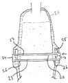
도 2는 본 발명의 환원 반응 노의 개략도를 도시하며,
도 3은 위로부터 수직 하향으로 본, 도 2에 그려진 장치의 개략도를 도시하며,
도 4는 층 아래에 구현된 자유 공간을 갖춘 환원 가스 채널 본체의 개략도를 도시하며,
도 5는 본 발명의 장치의 다른 형태의 실시예에 대한 도 3에 그려진 것과 유사한 개략도를 도시하며,
도 6은 본 발명의 장치의 한 섹션에 대한 개략도를 도시하며,
도 7은 도 6의 A-A' 일점 쇄선에 따른 섹션의 개략도를 도시한다.
냉각은 명료성 향상의 이유로 도 2 내지 도 7에 도시되지 않았지만, 그 냉각은 도 8에 스케치되어 있다.The present invention will be described in more detail below based on conventional schematics for the forms of embodiments.
1 shows a schematic view of a reduction reaction furnace according to the prior art,
Figure 2 shows a schematic diagram of the reduction reaction furnace of the present invention,
Figure 3 shows a schematic view of the device depicted in Figure 2, viewed vertically downward from above,
Figure 4 shows a schematic view of a reducing gas channel body with a free space implemented below the layer,
Figure 5 shows a schematic view similar to that depicted in Figure 3 for another embodiment of the apparatus of the present invention,
Figure 6 shows a schematic view of one section of the device of the present invention,
FIG. 7 shows a schematic view of a section along AA 'dot-dashed line in FIG.
The cooling is not shown in Figs. 2 to 7 for reasons of clarity improvement, but the cooling is sketched in Fig.
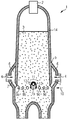
도 1은 종래 기술에 따라서, 환원 반응 노(1)에서 공급 설비(2)를 경유하여 도입되는 산화 철을 함유하는 분광 형태인 재료가 층(3)을 형성하는 것을 도시한다. - 꽉찬 단부를 갖춘 굽은 선의 화살표(wavy-line arrow)들로 나타낸 - 환원 가스(4)가 층을 통해 유동하며, 그렇게 함으로써 괴광을 해면 철로 환원한다. 명료하게 할 목적으로, 도면은 환원 반응 노로부터 사용된 환원 가스를 제거하기 위한 장치의 부품들을 도시하지 않았다. 환원 가스(4)는 환원 반응 노(1)의 내화성 외벽(5) 내에 형성된 내부 버슬(internal bustle)(6)로 운반된다. 환원 반응 노(1)의 내부에서 종결되는 환원 반응 노의 내부로 환원 가스를 도입하기 위한 다수의 환원 가스 입구 라인들이 - 여기서는 버슬 슬롯(7)들 - 내부 버슬(6)로부터 나온다. 종래 기술에 따라서, 이들 버슬 슬롯(7)에 의해 환원 가스가 층으로 도입된다. 환원 반응 노의 내부 직경의 차이(step)로 인해서, 층에 의해 충전되지 않은 링-형상 공간(8)이 환원 반응 노의 전체 원주 주위에 형성된다.
Fig. 1 shows that, in accordance with the prior art, a material in spectral form containing iron oxide introduced via a
도 1과 아주 유사한 본 발명의 장치를 묘사하는 도 2에서, 도 1에 사용된 참조 부호들은 명료함의 이유로 대부분 생략되었다. 다수의 버슬 슬롯(7)들의 출구(9a,9b,9c,9d)들이 명시되어 있으며, 명료함의 이유로 명시된 모든 출구에는 별도의 도면 부호가 주어지지 않았다. 버슬 슬롯의 출구(9a,9b,9c,9d)들은 버슬 슬롯(7)들의 환원 가스 출구들이다. 이들은 수평 평면(10)에 놓인다. 환원 가스 채널 본체(11)는 환원 반응 노(1)의 내부를 통과한다. 환원 가스 채널 본체는 캐리어 튜브(carrier tube)(12)에 맞대여 놓이는 하향으로 연장된 벽들을 갖춘 바닥으로 개방되는 하프 튜브 쉘(half tube shell)(13)로서 구현된다. 캐리어 튜브(12)는 과도하게 상세한 것으로서 도시되지 않은 환원 반응 노의 재킷(jacket)(14) 상에 양 측면들이 지지된다. 환원 가스 채널 본체(11)는 수평으로 연장하며 직경으로서의 내부를 통과한다. 이는 수직으로 보았을 때, 버슬 슬롯드의 마우스들이 내부에 놓여 있는 환원 반응 노의 직경의 최대 100% - 경우에 30% 미만으로 도시됨 - 의 두께를 가지는 환원 반응 노의 수직 길이방향 범위의 그 섹션 내에 놓여 있다. 환원 가스 채널 본체(11)의 내부 벽 측 양 단부들에서, 환원 노의 내부로 환원 가스를 공급하기 위한 환원 가스 공급 라인이 환원 가스 채널 본체(11)의 수직 아래로 존재하며 - 이 경우에, 내부 버슬(6)의 일부 섹션이 환원 반응 노(1)의 내부로 환원 가스 채널 본체(11)의 수직 아래로 개방되어 있다 -, 이러한 개구(15)는 직사각형으로 개략적으로 도시된다. 캐리어 튜브(12)는 작동 중에 냉각 매체로서 캐리어 튜브를 통해 유동하는 물을 가지나, 명료함을 향상시키기 위해서 이는 별도로 도시되지 않았다.
In Figure 2 depicting the apparatus of the present invention, which is very similar to Figure 1, the reference numerals used in Figure 1 have been largely omitted for reasons of clarity. The
도 3은 위에서 수직 하향으로 본, 도 2에 그려진 장치의 도면을 도시한다. 버슬(5)의 두 개의 이송부(16a 및 16b)들은 환원 가스 채널 본체(1)의 내부 벽 측 단부(17a,17b)들 아래로 환원 가스 공급 라인 - 도 3에서 볼 수 없음 - 의 위치에 대해 본질적으로 90°만큼 환원 반응 노(1)의 원주에 관하여 오프셋(offset)되어 있다. 환원 가스 채널 본체의 캐리어 튜브는 작동 중에 냉각 매체로서 캐리어 튜브를 통해 유동하는 물을 가지나, 명료함을 향상시키기 위해서 이는 추가로 도시되지 않았다.
Figure 3 shows a view of the device depicted in Figure 2, viewed vertically downward from above. The two
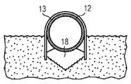
도 4는 환원 가스 채널 본체(11)에 대하여, 자유 공간(18)이 어떻게 층 내에서 그 본체 아래에 구현되는가에 대한 개략도를 도시한다. 캐리어 튜브(12)는 연장된, 본질적으로 평행한 벽들을 갖춘 하프 튜브 쉘(13)을 운반한다. 캐리어 튜브 상의 연장된 측면 벽들이 층층(3)의 압력 하에서 굽혀지는 것을 방지하도록 웨브(web)들에 의해 지지되는 것이 또한 도시된다. 대응 자유 공간이 전술한 플라잉 튜브(flying tube)들의 유사한 구성을 위해 형성된다.
4 shows a schematic view of how the
캐리어 튜브(12)는 작동 중에 냉각 매체로서 캐리어 튜브를 통해 유동하는 물을 가지나, 명료함을 향상시키기 위해서 이는 추가로 도시되지 않았다.
도 5는 본 발명의 장치의 다른 형태의 실시예에 대한, 도 3에 그려진 것과 유사한 개략도를 도시한다. 여기에는 두 개의 부품(19a 및 19b)들로 구성되는 외부 버슬이 존재한다. 이송부(22 및 23)들에 의해서 환원 가스가 공급된다. 외부 버슬은 또한, 완전 링으로서 구현될 수 있으나, 이는 그러나 과도한 도면으로 도시되지 않았다. 환원 가스 채널 본체(11)는 두 개의 부품(19a 및 19b)들을 연결한다. 버슬 슬롯(20)들은 외부 버슬로부터 나오며, 환원 반응 노의 재킷(14) 내부에서 내부의 급격한 확대의 결과로써 층 내에 형성되는, 점선으로 나타낸 링-형상 구역에서 넓어진다. 유사하게, 환원 가스의 도입 목적으로 재킷(14) 상에 환원 가스 채널 본체처럼 지지되는 유출 플라잉 튜브들이 있다. 이들은 환원 반응 노의 내부에서 종결된다. 환원 가스 채널 본체의 캐리어 튜브는 작동 중에 냉각 매체로서 캐리어 튜브를 통해 유동하는 물을 가지나, 명료함을 향상시키기 위해서 이는 추가로 도시되지 않았다.
Figure 5 shows a schematic view similar to that depicted in Figure 3 for another embodiment of the apparatus of the present invention. There is an external bead composed of two
도 2 내지 도 5에 그려진 도면들에서, 해면 철을 제조하기 위한 본 발명의 공정이 수행될 때, 환원 가스의 제 1 부분 양이 환원 반응 노의 내부 - 외부 또는 내부 버슬들의 버슬 슬롯들, 또는 외부 버슬에서 나오는 플라잉 튜브 - 에서 종결되는 다수의 도입 가스 입구 라인들에 의해서 층으로 도입된다. 환원 가스의 제 2 부분 양은 제 2 부분 양이 본질적으로, 환원 가스 채널 본체의 수직 아래로 환원 반응 노의 내부로 공급된 이후에 환원 반응 노를 통해 통과하는 환원 가스 채널에 의해서 층으로 분배된다.
In the figures drawn in Figures 2 to 5, when the process of the present invention for producing sponge iron is carried out, the first portion amount of reducing gas is introduced into the bezel slots of the inner-outer or inner beads of the reduction reaction furnace, Is introduced into the bed by a number of inlet gas inlet lines terminating in a flying tube - exiting from the outer vessel. The second portion amount of reducing gas is distributed to the layer by a reducing gas channel through which the second portion amount is essentially passed through the reduction reaction furnace after being fed into the reduction reaction furnace vertically below the reducing gas channel body.
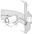
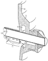
도 6 및 도 7은 환원 반응 노의 내부로 환원 가스를 공급하기 위한 환원 가스 공급 라인으로서 도 3 및 도 4에서 기능을 하는 내부 버슬(6)의 일부 섹션이 어떻게 환원 가스 채널 본체(11)의 수직 아래로 구현되는가를 개략적으로 도시한다. 따라서 환원 가스의 제 1 부분 양 및 환원 가스의 제 2 부분 양은 동일한 내부 버슬로부터 전달된다. 내부 버슬(6)은 하향 지향 확대부(expansion pointing downwards)를 가지며, 버슬 슬롯(7)들의 마우스들이 내측으로 넓어지는 링-형상 구역과 대략 동일한 평면 내에 환원 가스 채널 본체(11) 아래의 자유 공간(18)이 놓이도록 환원 가스 채널 본체(11)가 놓여 진다. 도 6은 본 발명의 장치의 섹션을 도시한다. 내부 버슬(6)이 환원 반응 노의 재킷(14) 내의 내화 외벽(5) 내에 존재한다. 내부 버슬(6)의 일부 섹션은 하향으로 확대된다. 내부로부터 내부 버슬(6)을 구획하는 외벽이 크로스해칭선(crosshatch)으로 도시된다. 내부 버슬(6) 내에 도시된 것은 내부 버슬(6)의 바닥 구역 내의 버슬 슬롯(7)들의 다수의 개구들이며, 바닥의 경계들은 점선들로 도시된다. 마우스(9e)를 갖춘 버슬 슬롯(7)이 횡-단면으로 도시된다.
6 and 7 show how a portion of the
하향으로 확대되는 내부 버슬(6)의 일부 섹션에서 환원 가스 채널 본체(11)는 크로스해칭선으로 도시된 벽을 통해 내부로 진입한다. 명료성의 향상을 위해서 캐리어 튜브(12) 및 하프 튜브 쉘(13)을 갖춘 환원 채널 본체(11)의 단지 일부 섹션만이 도시된다. 환원 가스 채널 본체(11) 아래의 수직으로 크로스해칭선으로 도시된 벽은 개구(15)를 가지며 그 개구를 통해서 환원 가스가 내부로 도입된다. 이러한 개구(15)는 내부 버슬(6)로부터 나오는 환원 가스 공급 라인이다. 환원 가스 채널 본체(11)는 환원 가스 채널 본체(11) 아래의 자유 공간(18)이 버슬 슬롯들의 마우스들과 대략 동일한 평면 내에 놓이도록 놓여 지며, 명료함을 향상시킬 목적으로 단지 하나, 즉 마우스(9e)만이 도시된다.
The reducing
도 7은 도 6에 끼워넣어 도시된 A-A' 라인을 따른 섹션을 도시한다. 버슬(6)로부터 관통 개구(15) 외측으로 그리고 환원 가스 채널 본체(11) 아래의 구역 내측으로의 - 머리가 꽉찬 곡선 화살표들로 도시된 - 환원 가스(4)의 유동 경로가 예시된다.
FIG. 7 shows a section along line AA 'shown interposed in FIG. The flow path of the reducing
환원 가스 채널 본체의 캐리어 튜브는 도 6 및 도 7에서, 작동 중에 캐리어 튜브를 통해 유동하는 냉각 매체로서 물을 가지나, 명료함을 향상시키기 위해서 이는 부가로 도시되지 않았다.
The carrier tube of the reducing gas channel body has water as a cooling medium flowing through the carrier tube during operation in Figures 6 and 7, but this is not shown to further improve clarity.
명료성 향상의 이유들로 냉각이 도 2 내지 도 7에 도시되지 않았지만, 냉각은 본 발명의 장치를 통한 횡단면으로 도 8에 스케치되어(sketched) 있다. 냉각수가 어떻게 캐리어 튜브(24) 내측으로 도입되고 캐리어 튜브(24)로부터 제거되는지가 화살표들에 의해 도시된다. 캐리어 튜브(24)는 캐리어 튜브가 속하는 환원 가스 채널 본체의 두 개의 내부 벽 측 단부들에서, 환원 가스의 공급을 위한 환원가스 공급 라인들이 아래에 존재하도록 환원 반응 노(25) 내에 설치된다. 이는 도 8에서 내부 버슬(25) 및 그로부터 나오는 버슬 슬롯(26)들에 의해 개략적으로 도시된다. 캐리어 튜브(24)에 의해 커버되는 횡-단면의 일부에서 버슬(25) 또는 버슬 슬롯들의 외형들이 크로스 해칭선으로 도시된다. 그 내측에, 캐리어 튜브(24)는 냉각 매체 공급 공간(27) 및 냉각 매체 제거 공간(28)을 소유한다. 이들은 캐리어 튜브(24) 내에서 캐리어 튜브(24)와 동심으로 배열되는 냉각 채널 튜브(29)에 의해 서로로부터 분리된다. 외부 냉각 매체 공급 공간에서, 냉각수는 공급 튜브의 단부까지 유동하며, 거기에서 운동 그의 윤동 방향을 변경하며 냉각 매체 제거 공간을 통해 다시 유동하고 캐리어 튜브로부터 운반된다.
Although cooling is not shown in Figures 2-7 for reasons of clarity, cooling is sketched in Figure 8 in cross-section through the apparatus of the present invention. How cooling water is introduced into
본 발명이 바람직한 전형적인 실시예들에 의해 더욱 상세하게 예시되고 설명되었지만, 본 발명은 설명된 예들에 의해 한정되지 않으며 다른 변형예들이 본 발명의 보호 범주로부터 이탈함이 없이 당업자에 의해 전형적인 실시예들로부터 파생될 수 있다.
Although the present invention has been illustrated and described in more detail by the preferred exemplary embodiments, it is to be understood that the invention is not to be limited by the exemplified embodiments, and that other modifications may be made by those skilled in the art without departing from the protective scope of the invention. Lt; / RTI >
1 : 환원 반응 노
2 : 공급 설비
3 : 층
4 : 환원 가스
5 : 내화 외벽
6 : 내부 버슬
7 : 버슬 슬롯
8 : 링-형상 공간
9a, 9b, 9c, 9d : 버슬 슬롯(7)들의 마우스들
10 : 버슬 슬롯(7)들의 마우스(9a, 9b, 9c, 9d)들이 놓이는 수평 평면(10)
11 : 환원 가스 채널 본체
12 : 캐리어 튜브
13 : 하프 튜브 쉘
14 : [환원 반응 노(1)의]재킷
15 : 개구
16a, 16b : 버슬(5)들의 이송부들
17a, 17b : 환원 가스 채널 본체(1)의 내부 벽 측 단부들
18 : 자유 공간
19a, 19b : 외부 버슬의 부분들
20 : 버슬 슬롯들
21 : 플라잉 튜브
22 : 이송부
23 : 이송부
24 : 캐리어 튜브
25 : 내부 버슬
26 : 버슬 슬롯들
27 : 냉각 매체 공급 공간
28 : 냉각 매체 제거 공간
29 : 냉각 채널 튜브
인용 문헌들의 목록
특허 문헌
EP 0 904 415 B1
WO 2009000409
WO 0036159
WO 00361571: reduction reaction furnace
2: Supply Facility
3rd Floor
4: Reduction gas
5: Outer wall of fireproof
6: Inner belly
7: Bass slot
8: Ring-shaped space
9a, 9b, 9c, 9d:
10: a horizontal plane (10) in which the mouse (9a, 9b, 9c, 9d)
11: Reduction gas channel body
12: Carrier tube
13: Half Tube Shell
14: [of reduction reaction furnace (1)] jacket
15: aperture
16a, 16b: conveying parts of the
17a and 17b: the inner wall side ends of the reducing gas channel body 1
18: free space
19a, 19b: parts of the outer bead
20: Bass slots
21: Flying tube
22:
23:
24: Carrier tube
25: Inner belly
26: Bass slots
27: Cooling medium supply space
28: Cooling medium removal space
29: cooling channel tube
List of citations
Patent literature
EP 0 904 415 B1
WO 2009000409
WO 0036159
WO 0036157
Claims (8)
- 환원 반응 노(1), 및
- 상기 환원 반응 노(1)의 내부로 환원 가스를 도입하기 위해 환원 반응 노(1)의 내부에서 종결되는 다수의 환원 가스 입구 라인들을 포함하는, 스펀지 메탈 또는 선철을 제조하는 장치에 있어서,
- 환원 반응 노(1)의 내부로 환원 가스를 분배하기 위해 환원 반응 노(1)의 내부를 통해 통과하는 환원 가스 채널 본체(11)가 제공되며,
- 환원 가스 채널 본체(11)의 하나 이상의 내벽 측 단부 상에서, 본질적으로 환원 가스 채널 본체(11) 아래의 수직으로, 환원 반응 노(1)의 내부의 환원 가스 채널 본체 아래에 환원 가스를 공급하기 위한 하나 이상의 환원 가스 입구 라인이 제공되며,
- 환원 가스 채널 본체(11)가 캐리어 튜브를 가지며 상기 캐리어 튜브를 통해 냉각 매체가 유동할 수 있는 것을 특징으로 하는,
스펀지 메탈 또는 선철을 제조하는 장치.
An apparatus for producing sponge metal or pig iron from spectra of a material containing a metal oxide using a reducing gas,
- reduction reaction furnace (1), and
- a plurality of reducing gas inlet lines terminating in a reduction reaction furnace (1) for introducing a reducing gas into the reduction reaction furnace (1), the apparatus comprising:
- a reducing gas channel body (11) is provided which passes through the interior of the reduction reaction furnace (1) to distribute the reducing gas to the interior of the reduction reaction furnace (1)
Supplying a reducing gas under the reducing gas channel body inside the reduction reaction furnace 1, essentially perpendicularly below the reducing gas channel body 11, on at least one inner wall side end of the reducing gas channel body 11, At least one reducing gas inlet line is provided,
Characterized in that the reducing gas channel body (11) has a carrier tube and the cooling medium can flow through the carrier tube,
Apparatus for manufacturing sponge metal or pig iron.
환원 가스 반응 노(1)의 내부에 놓이는 환원 가스 입구 라인들의 환원 가스 출구들은 모두 수직 방향으로 보았을 때, 환원 반응 노(1)의 직경의 100%까지의 두께를 가지는 환원 반응 노(1)의 수직 길이방향 범위의 섹션 내부에 놓이는 것을 특징으로 하는,
스펀지 메탈 또는 선철을 제조하는 장치.
The method according to claim 1,
The reducing gas outlets of the reducing gas inlet lines placed in the reducing gas reaction furnace 1 are all arranged in a direction perpendicular to the axis of the reducing reaction furnace 1 having a thickness up to 100% Characterized in that it lies within the section of the vertical longitudinal extent,
Apparatus for manufacturing sponge metal or pig iron.
환원 가스 채널 본체 아래에 환원 가스를 공급하기 위한 환원 가스 공급 라인 및 적어도 몇몇, 바람직하게 모두의 환원 가스 입구 라인들에는 동일한 내부 및/또는 외부 버슬로부터 환원 가스가 공급되는 것을 특징으로 하는,
스펀지 메탈 또는 선철을 제조하는 장치.
3. The method according to claim 1 or 2,
Characterized in that a reducing gas feed line for supplying a reducing gas below the reducing gas channel body and at least some, preferably both, reducing gas inlet lines are supplied with reducing gas from the same inner and /
Apparatus for manufacturing sponge metal or pig iron.
환원 가스 채널 본체(11)는 수직으로 보았을 때, 환원 가스 입구 라인들의 환원 가스 출구들이 놓이는 환원 반응 노(1)의 직경의 100%, 바람직하게 40%, 특히 바람직하게 30%, 아주 특히 바람직하게 20%까지의 두께를 가지는 환원 반응 노(1)의 수직 길이방향 범위의 그 섹션 내부에 적어도 부분적으로 놓이는 것을 특징으로 하는,
스펀지 메탈 또는 선철을 제조하는 장치.
4. The method according to any one of claims 1 to 3,
The reduction gas channel body 11 is 100%, preferably 40%, particularly preferably 30%, of the diameter of the reduction reaction furnace 1 in which the reducing gas outlets of the reduction gas inlet lines are located, Characterized in that it lies at least partially inside the section of the vertical longitudinal extent of the reduction reaction furnace (1) having a thickness of up to 20%
Apparatus for manufacturing sponge metal or pig iron.
내부 또는 외부 버슬에는 하나 이상의 환원 가스 이송부가 제공되며, 상기 이송부를 통해서 환원 가스가 내부 또는 외부 버슬의 내측으로 운반되며, 상기 하나 이상의 이송부는 환원 반응 노(1)의 원주에 관하여, 환원 가스 채널 본체(11)의 내벽 측 단부 아래의 환원 가스 공급 라인의 위치로 바람직하게, 45°내지 90°, 특히 바람직하게, 90°만큼 오프셋되는 것을 특징으로 하는,
스펀지 메탈 또는 선철을 제조하는 장치.
5. The method according to any one of claims 1 to 4,
The inner or outer bead is provided with at least one reduced gas delivery section through which the reducing gas is conveyed to the inside or outside of the outer bead, Is preferably offset by 45 [deg.] To 90 [deg.], Particularly preferably 90 [deg.] To the position of the reducing gas supply line below the inner wall side end of the main body 11. [
Apparatus for manufacturing sponge metal or pig iron.
환원 가스 채널 본체(11) 및 아마도, 플라잉 튜브(21)들이 존재하는 그의 길이방향 범위의 구역에서 환원 반응 노(1)의 내부 직경은 그의 길이방향 범주의 다른 구역들과 관련하여 확대되는 것을 특징으로 하는,
스펀지 메탈 또는 선철을 제조하는 장치.
6. The method according to any one of claims 1 to 5,
The inner diameter of the reduction reaction furnace 1 in the region of its longitudinal range in which the reducing gas channel body 11 and possibly the flying tubes 21 are present is characterized in that it is enlarged in relation to other zones in its longitudinal category As a result,
Apparatus for manufacturing sponge metal or pig iron.
환원 가스의 제 2 부분 양은 환원 반응 노의 내부를 통과하는 환원 가스 채널 본체에 의해서 층 내부로 분배되며, 환원 가스의 이러한 제 2 부분 양은 환원 반응 노의 내부의 환원 가스 채널 본체의 본질적으로 수직 아래로 공급되는 것을 특징으로 하는,
스펀지 메탈 또는 선철을 제조하는 방법.
A first portion of the reducing gas is introduced into the layer by a plurality of reducing gas inlet lines terminating within the reducing reaction furnace and the reducing gas is used to remove sponge metal from the spectroscopic layer of the metal oxide- Or a method for producing pig iron,
The amount of the second portion of the reducing gas is distributed into the layer by the reducing gas channel body passing through the interior of the reducing reaction furnace and the amount of this second portion of the reducing gas is essentially perpendicular to the bottom of the reducing gas channel body inside the reducing reaction furnace Is supplied to the < RTI ID = 0.0 >
Sponge metal or pig iron.
상기 제 1 부분 양 및 제 2 부분 양은 동일한 내부 및/또는 외부 버슬로부터 분배되는 것을 특징으로 하는,
스펀지 메탈 또는 선철을 제조하는 방법.
8. The method of claim 7,
Characterized in that the first partial amount and the second partial amount are distributed from the same internal and / or external budget.
Sponge metal or pig iron.
Applications Claiming Priority (3)
| Application Number | Priority Date | Filing Date | Title |
|---|---|---|---|
| EP20120164635 EP2653568A1 (en) | 2012-04-18 | 2012-04-18 | Device and method for gassing areas in a reduction reactor shaft |
| EP12164635.0 | 2012-04-18 | ||
| PCT/EP2013/058048 WO2013156548A1 (en) | 2012-04-18 | 2013-04-18 | Apparatus and process for surface gasification in a reduction reactor shaft |
Publications (1)
| Publication Number | Publication Date |
|---|---|
| KR20150004860A true KR20150004860A (en) | 2015-01-13 |
Family
ID=48190930
Family Applications (1)
| Application Number | Title | Priority Date | Filing Date |
|---|---|---|---|
| KR20147032326A KR20150004860A (en) | 2012-04-18 | 2013-04-18 | Apparatus and process for surface gasification in a reduction reactor shaft |
Country Status (11)
| Country | Link |
|---|---|
| US (1) | US20150114180A1 (en) |
| EP (2) | EP2653568A1 (en) |
| KR (1) | KR20150004860A (en) |
| CN (1) | CN104245964A (en) |
| AU (1) | AU2013251098A1 (en) |
| CA (1) | CA2870594A1 (en) |
| IN (1) | IN2014DN07623A (en) |
| RU (1) | RU2618037C2 (en) |
| UA (1) | UA113428C2 (en) |
| WO (1) | WO2013156548A1 (en) |
| ZA (1) | ZA201406290B (en) |
Families Citing this family (3)
| Publication number | Priority date | Publication date | Assignee | Title |
|---|---|---|---|---|
| EP3486335A1 (en) | 2017-11-15 | 2019-05-22 | Primetals Technologies Austria GmbH | Reducing gas supply for direct reduction |
| SE546071C2 (en) * | 2021-11-30 | 2024-05-07 | Hybrit Dev Ab | A system for direct reduction of iron ore to sponge iron |
| EP4350010A1 (en) | 2022-10-05 | 2024-04-10 | Primetals Technologies Austria GmbH | Iron melt from sinter |
Family Cites Families (9)
| Publication number | Priority date | Publication date | Assignee | Title |
|---|---|---|---|---|
| DE1458762A1 (en) * | 1965-07-29 | 1969-03-13 | Huettenwerk Oberhausen Ag | Shaft furnace for the direct reduction of iron ore |
| US3799521A (en) * | 1973-02-01 | 1974-03-26 | Fierro Esponja | Method and apparatus for the gaseous reduction of iron ore to sponge iron |
| US3853538A (en) * | 1973-07-20 | 1974-12-10 | Steel Corp | Use of reducing gas by coal gasification for direct iron ore reduction |
| US4118017A (en) * | 1976-01-02 | 1978-10-03 | United States Steel Corporation | Shaft furnace design |
| GB2016124B (en) * | 1978-03-11 | 1982-06-09 | Hamburger Stahlwerke Gmbh | Rocess and apparatus for the direct reduction of iron ores |
| DE19625127C2 (en) * | 1996-06-12 | 1998-04-30 | Voest Alpine Ind Anlagen | Device and method for producing sponge iron |
| IT1302813B1 (en) * | 1998-12-11 | 2000-09-29 | Danieli & C Ohg Sp | DEVICE FOR THE DIRECT REDUCTION OF IRON OXIDES AND RELATED PROCEDURE |
| IT1302815B1 (en) * | 1998-12-11 | 2000-09-29 | Danieli & C Ohg Sp | PROCEDURE AND APPARATUS FOR DIRECT REDUCTION OF MINERAL DIFERRO WITH OPTIMIZED INJECTION OF REDUCING GAS |
| AT505490B1 (en) | 2007-06-28 | 2009-12-15 | Siemens Vai Metals Tech Gmbh | METHOD AND DEVICE FOR PRODUCING IRON SPONGE |
-
2012
- 2012-04-18 EP EP20120164635 patent/EP2653568A1/en not_active Withdrawn
-
2013
- 2013-04-18 RU RU2014145209A patent/RU2618037C2/en not_active IP Right Cessation
- 2013-04-18 KR KR20147032326A patent/KR20150004860A/en not_active Application Discontinuation
- 2013-04-18 EP EP13719051.8A patent/EP2839042B1/en not_active Not-in-force
- 2013-04-18 AU AU2013251098A patent/AU2013251098A1/en not_active Abandoned
- 2013-04-18 UA UAA201411313A patent/UA113428C2/en unknown
- 2013-04-18 IN IN7623DEN2014 patent/IN2014DN07623A/en unknown
- 2013-04-18 US US14/390,813 patent/US20150114180A1/en not_active Abandoned
- 2013-04-18 CN CN201380020715.7A patent/CN104245964A/en active Pending
- 2013-04-18 CA CA2870594A patent/CA2870594A1/en not_active Abandoned
- 2013-04-18 WO PCT/EP2013/058048 patent/WO2013156548A1/en active Application Filing
-
2014
- 2014-08-26 ZA ZA2014/06290A patent/ZA201406290B/en unknown
Also Published As
| Publication number | Publication date |
|---|---|
| UA113428C2 (en) | 2017-01-25 |
| RU2014145209A (en) | 2016-06-10 |
| ZA201406290B (en) | 2016-09-28 |
| RU2618037C2 (en) | 2017-05-02 |
| EP2839042B1 (en) | 2016-05-18 |
| EP2653568A1 (en) | 2013-10-23 |
| CN104245964A (en) | 2014-12-24 |
| IN2014DN07623A (en) | 2015-05-15 |
| EP2839042A1 (en) | 2015-02-25 |
| WO2013156548A1 (en) | 2013-10-24 |
| CA2870594A1 (en) | 2013-10-24 |
| AU2013251098A1 (en) | 2014-10-09 |
| US20150114180A1 (en) | 2015-04-30 |
Similar Documents
| Publication | Publication Date | Title |
|---|---|---|
| US8901025B2 (en) | Catalyst regeneration zone divided into sectors for regenerative catalytic units | |
| EA014621B1 (en) | Method and apparatus for preparation of granular polysilicon | |
| CN102827642B (en) | Load-adjustable step feeding type entrained flow bed gasifier | |
| KR20150004860A (en) | Apparatus and process for surface gasification in a reduction reactor shaft | |
| KR20100085852A (en) | Apparatus for producing trichlorosilane and method for producing trichlorosilane | |
| US8783068B2 (en) | Batch charger cooling | |
| US4002422A (en) | Packed bed heat exchanger | |
| PL208220B1 (en) | Method for producing melamine | |
| US8361190B2 (en) | Process and apparatus for producing sponge iron | |
| RU2664069C2 (en) | Combined reactor for melamine synthesis at high pressure | |
| CN108531731A (en) | A kind of bottom reduction apparatus and the restoring method using the device | |
| JP5974596B2 (en) | Tuyere block | |
| KR20130039333A (en) | Cooling device for hot bulk material | |
| US6403022B1 (en) | Device for the direct reduction of iron oxides | |
| US3844251A (en) | Vapor deposition apparatus | |
| JP7094760B2 (en) | Fluidized bed reactor and method for producing acrylonitrile | |
| RU2165984C2 (en) | Method of charging metal carriers into melting-gasifying zone and plant for method embodiment | |
| ITUD980214A1 (en) | DEVICE FOR THE DIRECT REDUCTION OF IRON OXIDES AND RELATED PROCEDURE | |
| SU980804A1 (en) | Gas distributing apparatus | |
| KR101336302B1 (en) | Fluidized bed reactor for producing trichlorosilane | |
| CN114671439A (en) | Reduction furnace chassis cooling structure | |
| ITUD990160A1 (en) | OVEN FOR THE DIRECT REDUCTION OF IRON OXIDES | |
| JPH09210562A (en) | External particle circulating device in circulating fluidized bed type reducing device | |
| CN101260447A (en) | Pre-reduction furnace for non-blast furnace ironmaking | |
| ITUD990157A1 (en) | OVEN FOR THE DIRECT REDUCTION OF IRON OXIDES |
Legal Events
| Date | Code | Title | Description |
|---|---|---|---|
| A201 | Request for examination | ||
| A302 | Request for accelerated examination | ||
| E902 | Notification of reason for refusal | ||
| E601 | Decision to refuse application |