KR20150003864A - Bimetal buss bar assembly - Google Patents
Bimetal buss bar assembly Download PDFInfo
- Publication number
- KR20150003864A KR20150003864A KR1020147032786A KR20147032786A KR20150003864A KR 20150003864 A KR20150003864 A KR 20150003864A KR 1020147032786 A KR1020147032786 A KR 1020147032786A KR 20147032786 A KR20147032786 A KR 20147032786A KR 20150003864 A KR20150003864 A KR 20150003864A
- Authority
- KR
- South Korea
- Prior art keywords
- bus bar
- positive
- battery cell
- copper
- negative
- Prior art date
Links
Images


Classifications
-
- H—ELECTRICITY
- H01—ELECTRIC ELEMENTS
- H01M—PROCESSES OR MEANS, e.g. BATTERIES, FOR THE DIRECT CONVERSION OF CHEMICAL ENERGY INTO ELECTRICAL ENERGY
- H01M50/00—Constructional details or processes of manufacture of the non-active parts of electrochemical cells other than fuel cells, e.g. hybrid cells
- H01M50/50—Current conducting connections for cells or batteries
- H01M50/502—Interconnectors for connecting terminals of adjacent batteries; Interconnectors for connecting cells outside a battery casing
- H01M50/503—Interconnectors for connecting terminals of adjacent batteries; Interconnectors for connecting cells outside a battery casing characterised by the shape of the interconnectors
-
- H—ELECTRICITY
- H01—ELECTRIC ELEMENTS
- H01M—PROCESSES OR MEANS, e.g. BATTERIES, FOR THE DIRECT CONVERSION OF CHEMICAL ENERGY INTO ELECTRICAL ENERGY
- H01M50/00—Constructional details or processes of manufacture of the non-active parts of electrochemical cells other than fuel cells, e.g. hybrid cells
- H01M50/50—Current conducting connections for cells or batteries
- H01M50/502—Interconnectors for connecting terminals of adjacent batteries; Interconnectors for connecting cells outside a battery casing
- H01M50/521—Interconnectors for connecting terminals of adjacent batteries; Interconnectors for connecting cells outside a battery casing characterised by the material
- H01M50/522—Inorganic material
-
- H—ELECTRICITY
- H01—ELECTRIC ELEMENTS
- H01M—PROCESSES OR MEANS, e.g. BATTERIES, FOR THE DIRECT CONVERSION OF CHEMICAL ENERGY INTO ELECTRICAL ENERGY
- H01M50/00—Constructional details or processes of manufacture of the non-active parts of electrochemical cells other than fuel cells, e.g. hybrid cells
- H01M50/50—Current conducting connections for cells or batteries
- H01M50/502—Interconnectors for connecting terminals of adjacent batteries; Interconnectors for connecting cells outside a battery casing
- H01M50/521—Interconnectors for connecting terminals of adjacent batteries; Interconnectors for connecting cells outside a battery casing characterised by the material
- H01M50/526—Interconnectors for connecting terminals of adjacent batteries; Interconnectors for connecting cells outside a battery casing characterised by the material having a layered structure
-
- H—ELECTRICITY
- H01—ELECTRIC ELEMENTS
- H01M—PROCESSES OR MEANS, e.g. BATTERIES, FOR THE DIRECT CONVERSION OF CHEMICAL ENERGY INTO ELECTRICAL ENERGY
- H01M50/00—Constructional details or processes of manufacture of the non-active parts of electrochemical cells other than fuel cells, e.g. hybrid cells
- H01M50/50—Current conducting connections for cells or batteries
- H01M50/531—Electrode connections inside a battery casing
-
- H—ELECTRICITY
- H01—ELECTRIC ELEMENTS
- H01M—PROCESSES OR MEANS, e.g. BATTERIES, FOR THE DIRECT CONVERSION OF CHEMICAL ENERGY INTO ELECTRICAL ENERGY
- H01M50/00—Constructional details or processes of manufacture of the non-active parts of electrochemical cells other than fuel cells, e.g. hybrid cells
- H01M50/50—Current conducting connections for cells or batteries
- H01M50/543—Terminals
- H01M50/547—Terminals characterised by the disposition of the terminals on the cells
- H01M50/55—Terminals characterised by the disposition of the terminals on the cells on the same side of the cell
-
- H—ELECTRICITY
- H01—ELECTRIC ELEMENTS
- H01M—PROCESSES OR MEANS, e.g. BATTERIES, FOR THE DIRECT CONVERSION OF CHEMICAL ENERGY INTO ELECTRICAL ENERGY
- H01M50/00—Constructional details or processes of manufacture of the non-active parts of electrochemical cells other than fuel cells, e.g. hybrid cells
- H01M50/50—Current conducting connections for cells or batteries
- H01M50/543—Terminals
- H01M50/552—Terminals characterised by their shape
- H01M50/553—Terminals adapted for prismatic, pouch or rectangular cells
-
- H—ELECTRICITY
- H01—ELECTRIC ELEMENTS
- H01M—PROCESSES OR MEANS, e.g. BATTERIES, FOR THE DIRECT CONVERSION OF CHEMICAL ENERGY INTO ELECTRICAL ENERGY
- H01M50/00—Constructional details or processes of manufacture of the non-active parts of electrochemical cells other than fuel cells, e.g. hybrid cells
- H01M50/50—Current conducting connections for cells or batteries
- H01M50/543—Terminals
- H01M50/562—Terminals characterised by the material
-
- H—ELECTRICITY
- H01—ELECTRIC ELEMENTS
- H01M—PROCESSES OR MEANS, e.g. BATTERIES, FOR THE DIRECT CONVERSION OF CHEMICAL ENERGY INTO ELECTRICAL ENERGY
- H01M50/00—Constructional details or processes of manufacture of the non-active parts of electrochemical cells other than fuel cells, e.g. hybrid cells
- H01M50/50—Current conducting connections for cells or batteries
- H01M50/543—Terminals
- H01M50/564—Terminals characterised by their manufacturing process
- H01M50/566—Terminals characterised by their manufacturing process by welding, soldering or brazing
-
- H—ELECTRICITY
- H01—ELECTRIC ELEMENTS
- H01M—PROCESSES OR MEANS, e.g. BATTERIES, FOR THE DIRECT CONVERSION OF CHEMICAL ENERGY INTO ELECTRICAL ENERGY
- H01M2220/00—Batteries for particular applications
- H01M2220/20—Batteries in motive systems, e.g. vehicle, ship, plane
-
- Y—GENERAL TAGGING OF NEW TECHNOLOGICAL DEVELOPMENTS; GENERAL TAGGING OF CROSS-SECTIONAL TECHNOLOGIES SPANNING OVER SEVERAL SECTIONS OF THE IPC; TECHNICAL SUBJECTS COVERED BY FORMER USPC CROSS-REFERENCE ART COLLECTIONS [XRACs] AND DIGESTS
- Y02—TECHNOLOGIES OR APPLICATIONS FOR MITIGATION OR ADAPTATION AGAINST CLIMATE CHANGE
- Y02E—REDUCTION OF GREENHOUSE GAS [GHG] EMISSIONS, RELATED TO ENERGY GENERATION, TRANSMISSION OR DISTRIBUTION
- Y02E60/00—Enabling technologies; Technologies with a potential or indirect contribution to GHG emissions mitigation
- Y02E60/10—Energy storage using batteries
Abstract
바이메탈 버스 바 조립체(134)는, 평평한 패드(130)를 갖는 양의 배터리 셀 단자(120), 평평한 패드(132)를 갖는 음의 배터리 셀 단자(122), 및 음의 단부(144)와 양의 단부(142)를 갖는 버스 바(140)를 포함한다. 버스 바는, 양의 단부에서 양의 배터리 셀 단자에 부착되고 음의 단부에서 음의 배터리 셀 단자에 부착된다. 양의 배터리 셀 단자, 음의 배터리 셀 단자, 및 버스 바 중 적어도 하나는 바이메탈 계면(141)을 갖는다.The bimetallic bus bar assembly 134 includes a positive battery cell terminal 120 having a flat pad 130, a negative battery cell terminal 122 having a flat pad 132, and a negative battery cell terminal 122 having a negative end 144 and a positive And a bus bar 140 having an end 142 of the bus bar 140. The bus bar is attached to the positive battery cell terminal at the positive end and to the negative battery cell terminal at the negative end. At least one of a positive battery cell terminal, a negative battery cell terminal, and a bus bar has a bimetallic interface 141.
Description
본 개시 내용은 일반적으로 배터리 모듈에 관한 것이다. 전기 차량 또는 하이브리드 차량용 배터리 모듈 등의 배터리 모듈은, 통상적으로, 배터리 모듈들을 형성하도록 함께 그룹화된 복수의 셀을 포함한다. 배터리 모듈들은 함께 연결되어 배터리 팩들을 형성한다. 셀들의 각각은 함께 전기적으로 연결되는 양(positive)의 셀 단자와 음(negative)의 셀 단자를 포함한다. 서로 다른 유형의 배터리 모듈들은 서로 다른 유형의 셀들을 사용하여 형성된다. 예를 들어, 한 유형의 배터리 모듈들은 파우치형 배터리 모듈이라 하고, 다른 한 유형의 배터리 모듈들은 프리즘형 배터리 모듈이라 하고, 제3 유형의 배터리 모듈들은 원통형 배터리 모듈이라 한다.The present disclosure relates generally to battery modules. Battery modules, such as battery modules for electric vehicles or hybrid vehicles, typically include a plurality of cells grouped together to form battery modules. The battery modules are connected together to form battery packs. Each of the cells includes a positive cell terminal and a negative cell terminal electrically connected together. Different types of battery modules are formed using different types of cells. For example, one type of battery module is referred to as a pouch type battery module, another type of battery module is referred to as a prismatic battery module, and a third type of battery module is referred to as a cylindrical battery module.
프리즘형(prismatic) 배터리 모듈에서는 함께 적층되는 프리즘형 배터리 셀들을 사용한다. 양의 셀 단자와 음의 셀 단자는 버스 바를 이용하여 연결된다. 양의 셀 단자와 음의 셀 단자는 통상적으로 스레드형 포스트(threaded post) 또는 볼트를 포함한다. 버스 바는 너트를 사용하여 포스트에 연결된다. 통상적인 배터리 모듈은, 버스 바와 너트를 사용하여 각각 함에 연결되는 10개 이상의 배터리 셀을 포함한다. 이러한 연결은 시간 소모적이며, 토크 초과 또는 토크 부족, 또는 교차 스레딩 등의 다른 문제점들이 있을 수 있다.In a prismatic battery module, prismatic battery cells stacked together are used. Positive cell terminals and negative cell terminals are connected using a bus bar. Positive and negative cell terminals typically include threaded posts or bolts. The bus bar is connected to the post using a nut. A typical battery module includes ten or more battery cells each connected to a box using a bus bar and a nut. This connection is time consuming, and there may be other problems such as over torque or lack of torque, or crossover threading.
해결책은, 본 명세서에서 설명하는 바와 같은 바이메탈 버스 바 조립체를 제공하는 것으로서, 이 바이메탈 버스 바 조립체는, 평평한 패드를 갖는 양의 배터리 셀 단자, 평평한 패드를 갖는 음의 배터리 셀 단자, 및 음의 단부와 양의 단부를 갖는 버스 바를 포함한다. 버스 바는, 양의 단부에서 양의 배터리 셀 단자에 부착되고 음의 단부에서 음의 배터리 셀 단자에 부착된다. 양의 배터리 셀 단자, 음의 배터리 셀 단자, 및 버스 바 중 적어도 하나는 바이메탈 계면(bimetal interface)을 갖는다.The solution is to provide a bimetal bus bar assembly as described herein, wherein the bimetal bus bar assembly includes a positive battery cell terminal having a flat pad, a negative battery cell terminal having a flat pad, And a bus bar having a positive end. The bus bar is attached to the positive battery cell terminal at the positive end and to the negative battery cell terminal at the negative end. At least one of a positive battery cell terminal, a negative battery cell terminal, and a bus bar has a bimetal interface.
이제, 첨부 도면을 참조하며 본 발명을 예를 들어 설명한다.The present invention will now be described by way of example with reference to the accompanying drawings.
도 1은 예시적인 일 실시예에 따라 형성된 배터리 모듈의 상부 사시도.
도 2는 도 1에 도시한 배터리 모듈의 일부의 상부 사시도.
도 3은 배터리 모듈의 프리즘형 배터리 셀의 상부 사시도.
도 4는 예시적인 일 실시예에 따라 형성된 배터리 모듈을 위한 버스 바 조립체의 상부 사시도.
도 5는 예시적인 일 실시예에 따라 형성된 버스 바 조립체의 단면도.
도 6은 예시적인 일 실시예에 따라 형성된 버스 바 조립체의 단면도.
도 7은 예시적인 일 실시예에 따라 형성된 버스 바 조립체의 단면도.
도 8은 예시적인 일 실시예에 따라 형성된 버스 바 조립체의 단면도.
도 9는 예시적인 일 실시예에 따라 형성된 버스 바 조립체의 단면도.
도 10은 예시적인 일 실시예에 따라 형성된 버스 바 조립체의 단면도.
도 11은 예시적인 일 실시예에 따라 형성된 버스 바 조립체의 단면도.
도 12는 예시적인 일 실시예에 따라 형성된 버스 바 조립체의 단면도.1 is a top perspective view of a battery module formed in accordance with an exemplary embodiment;
FIG. 2 is a top perspective view of a portion of the battery module shown in FIG. 1; FIG.
3 is a top perspective view of a prismatic battery cell of a battery module.
4 is a top perspective view of a bus bar assembly for a battery module formed in accordance with an exemplary embodiment;
5 is a cross-sectional view of a bus bar assembly formed in accordance with an exemplary embodiment;
6 is a cross-sectional view of a bus bar assembly formed in accordance with an exemplary embodiment;
7 is a cross-sectional view of a bus bar assembly formed in accordance with an exemplary embodiment;
8 is a cross-sectional view of a bus bar assembly formed in accordance with an exemplary embodiment;
9 is a cross-sectional view of a bus bar assembly formed in accordance with an exemplary embodiment;
10 is a cross-sectional view of a bus bar assembly formed in accordance with an exemplary embodiment;
11 is a cross-sectional view of a bus bar assembly formed in accordance with an exemplary embodiment;
12 is a cross-sectional view of a bus bar assembly formed in accordance with an exemplary embodiment;
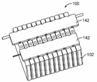
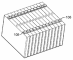
도 1은 예시적인 일 실시예에 따라 형성된 배터리 모듈(100)의 상부 사시도이다. 도 2는 배터리 모듈(100)의 배터리 셀들(102)을 예시하도록 버스 바들(140)을 위한 (도 4에 도시한) 버스 바 조립체들(134)과 (도 1에 도시한) 캐리어(142)가 제거되어 있는 배터리 모듈(100)의 상부 사시도이다. 배터리 모듈(100)은, 전기 차량이나 하이브리드 전기 차량 등의 차량의 배터리 시스템의 일부로서 사용될 수 있다. 배터리 모듈(100)은 대체 실시예들에서 다른 응용 분야들에서 사용될 수도 있다. 다수의 배터리 모듈들(100)을 함께 모아 배터리 팩을 형성할 수 있다.1 is a top perspective view of a
각 배터리 모듈(100)은 복수의 프리즘형 배터리 셀(102)을 포함한다. 프리즘형 배터리 셀들(102)은 적층 구성으로 나란히 배열되어 배터리 모듈(100)을 형성한다. 선택 사항으로, 배터리 모듈(100)은 프리즘형 배터리 셀들(102)을 유지하는 케이스 또는 기타 하우징을 포함할 수도 있다. 프리즘형 배터리 셀들(102)의 상부에 배터리 커버를 제공할 수 있다. 배터리 커버는 프리즘형 배터리 셀들(102)의 각각을 커버할 수 있다.Each
각 배터리 모듈(100)은 양의 배터리 단자(106)와 음의 배터리 단자(108)를 포함한다. 단자들(106, 108)은 외부 전력 케이블에 결합되도록 구성되거나 또는 대안으로 다른 배터리 모듈(100)의 배터리 셀 단자들에 버스 결합(buss)될 수 있다. 단부 배터리 단자들(106, 108)은 배터리 단자에 종단되며, 배터리 단자는, 예를 들어, 모듈간 커넥터를 사용하여 인접하는 배터리 모듈(100)의 배터리 케이블에 또는 배터리 셀에 연결될 수 있다.Each
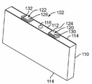
도 3은 예시적인 실시예에 따라 형성된 프리즘형 배터리 셀들(102) 중 하나의 상부 사시도이다. 프리즘형 배터리 셀(102)은 상부(112)와 측벽들(114)을 갖는 셀 하우징(110)을 포함한다. 예시한 실시예에서, 셀 하우징(110)은 4개의 측벽(114)을 갖는 박스 형상이다. 배터리 셀(102)은 상부(112) 상에 가스 압력 밸브(116)를 갖는다.3 is a top perspective view of one of the
각 배터리 셀(102)은 양의 배터리 셀 단자(120)와 음의 배터리 셀 단자(122)를 포함한다. 예시적인 일 실시예에서, 양의 배터리 셀 단자(120)는, 배터리 셀 단자들 간의 (도 4에 도시한) 버스 바(140)를 용접함으로써, 인접하는 배터리 셀(102)의 인접하는 음의 배터리 셀 단자(122)에 연결된다. 마찬가지로, 음의 배터리 셀 단자(122)는, 배터리 셀 단자들 간의 버스 바(104)를 용접함으로써, 인접하는 배터리 셀(102)의 인접하는 음의 배터리 살 단자(120)에 연결된다. 단부 배터리 셀들(102)의 셀 단자들(102, 122)은 (도 2에 도시한) 배터리 단자들(106, 108)을 규정할 수 있다.Each
예시적인 일 실시예에서, 양의 배터리 셀 단자(120)는 알루미늄이고, 음의 배터리 셀 단자(122)는 구리이다(부품이 금속 물질로 형성된다는 것은, 순수 금속으로 형성된 또는 이러한 금속 물질들의 합금으로 형성된 부품들을 포함한다). 양의 배터리 셀 단자(120)는, 배터리 셀(102)을 위한 컨덕터 또는 연결 계면(connection interface)으로서 사용되는, 상부(112)로부터 연장되는 포스트 또는 판(124)을 포함한다. 배터리 셀 단자(120)의 다른 단부는 배터리 셀 내로 연장된다. 예시한 실시예에서, 판(124)은 컨덕터 또는 연결 계면을 규정하는 상면을 갖는 평평한 패드(130)를 포함한다. 음의 배터리 셀 단자(122)는, 배터리 셀(102)을 위한 컨덕터 또는 연결 계면으로서 사용되는, 상부(112)로부터 연장되는 포스트 또는 판(126)을 포함한다. 배터리 셀 단자(122)의 다른 단부는 배터리 셀 내로 연장된다. 예시한 실시예에서, 판(126)은 컨덕터 또는 연결 계면을 규정하는 상면을 갖는 평평한 패드(132)를 포함한다.In an exemplary embodiment, the positive
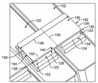
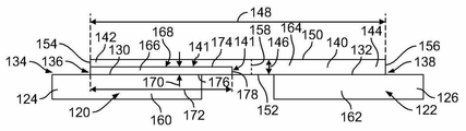
도 4는 예시적인 일 실시예에 따라 형성된 버스 바 조립체(134)의 상부 사시도이다. 버스 바 조립체(134)는, 인접하는 프리즘형 배터리 셀들(102)의 셀 단자들(120, 122)을 전기적으로 연결하는 데 사용된다. 버스 바 조립체(134)는, 버스 바(140), 양의 셀 단자 판(124), 및 음의 셀 단자 판(126)을 포함한다. 버스 바(140)는, 제1 계면(136)에서 양의 셀 단자(120)에 그리고 제2 계면(138)에서 인접하는 배터리 셀(102)의 대응하는 음의 셀 단자(122)에 종단되도록 구성된다. 예시적인 일 실시예에서, 버스 바(140)는 레이저 용접에 의해 단자들(120, 122)에 종단되며, 전술한 바와 같이, 계면들(136, 138)은 각각 레이저 용접된 계면들(136, 138)을 규정한다.4 is a top perspective view of a
예시적인 일 실시예에서, 버스 바 조립체(134)는, 일반적으로, (알루미늄 합금을 포함한) 알루미늄 세그먼트와 (구리 합금을 포함한) 구리 세그먼트를 포함하는 바이메탈 구조를 포함하며, 이러한 예들은 도 5 내지 도 12에 예시되어 있다. 세그먼트들은 바이메탈 계면(bimetal interface; 141)에서 접하며, 그 예는 도 5 내지 도 12에 예시되어 있다. 바이메탈 계면(141)은 알루미늄 세그먼트와 구리 세그먼트의 당접하는 모든 부분들을 따라 규정된다. 예시적인 일 실시예에서, 바이메탈 계면(141)은 레이저 용접 계면들(136, 138)과 일치하지 않는다. 제1 레이저 용접 계면(136)에서는, 유사한 금속 구조들이 함께 레이저 용접되고(예를 들어, 양측 구조들이 알루미늄 구조들일 수 있음), 제2 레이저 용접 계면(138)에서는, 유사한 금속 구조들이 함께 레이저 용접된다(예를 들어, 양측 구조들이 구리 구조들일 수 있다).In one exemplary embodiment,
버스 바(140)는 버스 바(140)의 양의 단부(142)에서 양의 판(124)에 연결되고 버스 바(140)의 음의 단부(144)에서 음의 판(126)에 연결된 대략 직사각형 판이다. 예시적인 일 실시예에서, 도 5를 더 참조해 보면, 버스 바(140)는 높이(146)와 폭(148)에 의해 규정되는 엔벨로프 또는 프로파일을 갖는다. 높이(146)는 버스 바(140)의 상부(150)와 하부(152) 사이로 규정된다. 하부(152)는 양의 판(124) 및 음의 판(126)과 대면하며, 조립 동안 평평한 패드들(130, 132)에 종단되도록 구성된다. 예시적인 일 실시예에서, 하부(152)는 계면들(136, 138)이 동일한 평면으로 되도록 평평하다. 폭(148)은 제1 단부(154)와 제2 단부(156) 사이로 규정된다. 단부들(154, 156)은 상부(150)와 하부(152) 사이에서 연장된다. 중심선(158)은 제1 단부(154)와 제2 단부(156) 사이의 중간으로 규정된다.The
예시적인 일 실시예에서, 버스 바(140) 및 양과 음의 판들(124, 126)은, 서로 별도로 제조되고, 이후에 제조 동안 종단되거나 연결된다. 각각은 순수 컨덕터 또는 바이메탈 컨덕터일 수 있다. 바이메탈 컨덕터는, 레이저 용접, 초음파 용접, 클래딩, 또는 다른 공정에 의해 두 개의 물질이 연결되는 두 개의 서로 다른 도전성 물질을 갖는다. 예시적인 일 실시예에서, 버스 바(140)의 양의 단부(142)와 음의 단부(144)는 각각 계면들(136, 138)에서 레이저 용접, 기타 용접 수단, 또는 다른 부착 수단에 의해 양의 판(124)과 음의 판(126)에 종단된다.In an exemplary embodiment,
도 5는 예시적인 일 실시예에 따라 형성된 버스 바 조립체(134)의 단면도이다. 버스 바 조립체(134)는, 레이저 용접 등에 의해, 평평한 패드들(130, 132)에서 버스 바(140)를 양과 음의 판들(124, 126)에 부착함으로써 제조된다. 양의 판(124)은 알루미늄 블록(160)으로 제조된다. 음의 판(126)은 구리 블록(162)으로 제조된다. "블록"은 단면에 있어서 직사각형일 수 있고, 또는 다른 실시예들에서 판으로부터 연장되는 포스트를 갖는 L 형상 등의 다른 형상을 가질 수도 있다.5 is a cross-sectional view of a
도 5의 실시예에서, 버스 바(140)는, 일반적으로 구리 물질의 층 또는 블록(164)으로 형성되고 평평한 패드(130)에 인접하는 양의 단부(142)에 도포된 알루미늄 물질의 층이나 스트립(166)을 갖는 바이메탈 바이다. 알루미늄 스트립(166)은 바이메탈 계면(141)에서 구리 블록(164)에 종단된다. 선택 사항으로, 알루미늄 스트립(166)은, 알루미늄 스트립(166)과 구리 블록(164)을 클래딩함으로써, 구리 블록(164)에 기계적으로 그리고 전기적으로 연결될 수 있다. 알루미늄 스트립(166)은, 다른 실시예들에서 레이저 용접, 초음파 용접, 또는 다른 적절한 수단 등의 다른 공정에 의해 구리 블록(164)에 종단될 수 있다. 알루미늄 스트립(166)은 구리 블록(164)에 연결될 넓은 대면적을 갖는다.In the embodiment of Figure 5, the
예시적인 일 실시예에서, 구리 블록(164)은, 알루미늄 스트립(166)을 수용하는 구리 블록(164)의 엔벨로프 내에 규정된 포켓(168)을 포함한다. 엔벨로프는 버스 바(140)의 동일한 엔벨로프일 수 있다. 알루미늄 스트립(166)은, 구리 블록(164)의 포켓(168) 내에 삽입(inset)되고, 구리 블록(164)의 엔벨로프 또는 프로파일 내에 끼워진다. 알루미늄 스트립(166)은 버스 바(140)의 높이(146)보다 낮은 높이(170)를 갖는다. 알루미늄 스트립(166)은 버스 바(140)의 폭(148)보다 작은 폭(172)을 갖는다. 구리 블록(164)은 알루미늄 스트립(166) 위로 버스 바(140)의 전체 폭(148)에 걸쳐 연장된다. 구리 블록(164)은 음의 단부(144)에서 버스 바(140)의 전체 높이(146)에 걸쳐 연장된다. 알루미늄 스트립(166)은, 상부(174), 양의 배터리 셀 단자(120)의 평평한 패드(130)에 대면하는 하부(170), 및 상부(174)와 하부(176) 사이의 에지(178)를 갖는다. 구리 블록(164)은, 알루미늄 스트립(166)의 두 개의 서로 수직인 면들을 따라 바이메탈 계면(141)을 규정하도록 상부(174) 및 에지(178)의 적어도 한 세그먼트를 따라 연장된다.In an exemplary embodiment, the
버스 바 조립체(134)는, 레이저 용접 또는 다른 적절한 수단에 의해 양의 단부(142) 영역에서 버스 바(140)의 알루미늄 스트립(166)을 양의 평평한 패드(130)에 기계적으로 그리고 전기적으로 종단함으로써 제조된다. 음의 단부(144)에서의 버스 바(140)의 구리 블록(164)은 레이저 용접 또는 다른 적절한 수단에 의해 음의 평평한 패드(132)에 종단된다. 버스 바(140)는 양과 음의 판들(124, 126)에 용접되며, 이때, 버스 바(140)의 양의 단부(142)의 알루미늄 스트립(166)은 알루미늄 판(124)의 알루미늄 패드(130)에 용접되고 버스 바(140)의 음 단부(144)의 구리 블록(164)은 구리 판(126)의 구리 패드(132)에 용접된다. 양과 음의 셀 단자 판들(124, 126) 간에 바이메탈 구조를 사용함으로써, 아연 도금(galvanizing)을 감소시키거나 제거할 수 있다.The
버스 바(140)는 인접하는 배터리 셀들(102) 간에 결합되며, 이때, 양의 배터리 셀 단자(120)의 양의 판(124)은 하나의 배터리 셀(102)에 종단되고, 대응하는 음의 배터리 셀 단자(122)의 음의 판(126)은 인접하는 배터리 셀(102)에 종단된다. 예시적인 일 실시예에서, 판들(124, 126)은 대응하는 단자들(120, 122)의 일부들이다. 레이저 용접은 스레드형 포스트 상의 너트와 볼트를 필요 없게 한다. 버스 바(140)는 레이저 용접에 의해 더욱 빠르게 종단될 수 있다. 레이저 용접은, 낮은 계면 저항을 갖는 계면 등의, (도 4에 도시한) 버스 바(140)와 단자들(120, 122) 간의 양호한 전기적 연결을 제공한다.The
도 6은 예시적인 일 실시예에 따라 형성된 버스 바 조립체(134)의 단면도이다. 버스 바 조립체(134)의 판들(124, 126)과 버스 바(140)는 서로 별도로 제조되며 제조 동안 함께 연결된다. 버스 바(140)의 양의 단부(142)와 음의 단부(144)는, 예를 들어, 레이저 용접, 기타 용접, 또는 기타 부착 수단에 의해 양과 음의 판들(124, 126)에 각각 종단된다. 버스 바(140)는 평평한 패드들(130, 132)에서 양과 음의 판들(124, 126)에 각각 용접된다.6 is a cross-sectional view of a
예시적인 일 실시예에서, 양의 판(124)은 알루미늄 블록(180)으로 제조된다. 음의 판(126)은 버스 바(140)에 인접하는 패드(132)에 도포된 알루미늄 물질의 층 또는 스트립(184)을 갖는 구리 블록(182)을 포함하는 바이메탈 판이다. 버스 바(140)는 알루미늄 물질의 블록 또는 바(186)이다. 버스 바 조립체(134)는, 음의 판(126)을 형성하도록, 예를 들어, 클래딩, 레이저 용접, 초음파 용접에 의해 알루미늄 스트립(184)을 구리 블록(182)에 종단함으로써, 또는 그 외에는 스트립(184)을 블록(182)에 종단함으로써 제조된다. 알루미늄 스트립(184)은 바이메탈 계면(141)에서 구리 블록(182)에 종단된다. 알루미늄 스트립(184)은 구리 블록(182)에 종단되기 위한 넓은 표면적을 제공한다.In one exemplary embodiment, the
예시적인 일 실시예에서, 구리 블록(182)은, 알루미늄 스트립(184)을 수용하는 구리 블록(182)의 엔벨로프 내에 규정된 포켓(188)을 포함한다. 엔벨로프는 음의 판(126)의 동일한 엔벨로프 또는 프로파일일 수 있다. 알루미늄 스트립(184)은, 구리 블록(182)의 포켓(188) 내에 삽입되고 구리 블록(182)의 엔벨로프 또는 프로파일 내에 끼워진다. 알루미늄 스트립(184)은 음의 판(126)의 높이보다 낮은 높이(190)를 갖는다. 알루미늄 스트립(184)은 음의 판(126)의 폭보다 작은 폭(192)을 갖는다. 구리 블록(182)은 알루미늄 스트립(184) 아래에서 음의 판(126)의 전체 폭에 걸쳐 연장된다. 구리 블록(182)은 음의 판(126)의 전체 높이에 걸쳐 연장된다. 알루미늄 스트립(184)은, 평평한 패드(132)의 적어도 일부를 규정하는 상부(194), 상부(194)의 반대측인 하부(196), 및 상부(194)와 하부(196) 사이의 에지(198)를 갖는다. 구리 블록(182)은, 알루미늄 스트립(184)의 두 개의 서로 수직하는 면들을 따라 바이메탈 계면(141)을 규정하도록 하부(196) 및 에지(198)의 적어도 한 세그먼트를 따라 연장된다.In an exemplary embodiment,
알루미늄 바(186)는, 예를 들어, 레이저 용접 계면(136)에서 레이저 용접 또는 기타 적절한 수단에 의해 음의 판(126)에 종단된다. 알루미늄 바(186)는, 예를 들어, 레이저 용접 계면(138)에서 레이저 용접 또는 기타 적절한 수단에 의해 양의 판(124)에 종단된다. 따라서, 버스 바(140)는 양과 음의 판들(124, 126)에 용접되고, 이때, 음의 판(126)의 알루미늄 스트립(184)은 버스 바(140)의 알루미늄인 음의 단부(144)에 용접되고, 알루미늄 판(124)의 알루미늄 블록(180)은 버스 바(140)의 알루미늄인 양의 단부(142)에 용접된다. 양과 음의 셀 단자 판들(124, 126) 간에 바이메탈 구조를 이용함으로써, 아연 도금을 감소시키거나 제거할 수 있다.The
버스 바(140)는 인접하는 배터리 셀들(102) 간에 결합되며, 이때, 양의 배터리 셀 단자(120)의 양의 판(124)은 하나의 배터리 셀(102)에 종단되고, 대응하는 음의 배터리 셀 단자(122)의 음의 판(126)은 인접하는 배터리 셀(102)에 종단된다. 예시적인 일 실시예에서, 판들(124, 126)은 대응하는 단자들(120, 122)의 일부들이다. 레이저 용접은 스레드형 포스트 상의 너트와 볼트를 필요 없게 한다. 버스 바(140)는 레이저 용접에 의해 더욱 빠르게 종단될 수 있다. 레이저 용접은, 낮은 계면 저항을 갖는 계면 등의, (도 4에 도시한) 버스 바(140)와 단자들(120, 122) 간의 양호한 전기적 연결을 제공한다.The
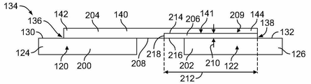
도 7은 예시적인 일 실시예에 따라 형성된 버스 바 조립체(134)의 단면도이다. 버스 바 조립체(134)의 판들(124, 126)과 버스 바(140)는 서로 별도로 제조되며 제조 동안 함께 연결된다. 버스 바(140)의 양의 단부(142)와 음의 단부(144)는, 예를 들어, 레이저 용접, 기타 용접, 또는 기타 부착 수단에 의해 양과 음의 판들(124, 126)에 각각 종단된다. 버스 바(140)는 평평한 패드들(130, 132)에서 양과 음의 판들(124, 126)에 각각 용접된다.7 is a cross-sectional view of a
예시적인 일 실시예에서, 양의 판(124)은 알루미늄 블록(200)으로 제조된다. 음의 판(126)은 구리 블록(202)으로 제조된다. 버스 바(140)는, 음의 단부(144)에서 버스 바(140)의 하부(208)에 도포된 구리 물질의 층 또는 스트립(206)을 갖는 알루미늄 블록(204)을 포함하는 바이메탈 바이다. 버스 바 조립체(134)는, 버스 바(140)를 조립하도록, 예를 들어, 클래딩, 용융, 레이저 용접, 초음파 용접에 의해 구리 스트립(206)을 알루미늄 블록(204)에 종단함으로써, 또는 그 외에는 스트립(206)을 블록(204)에 종단함으로써 제조된다. 구리 스트립(206)은 바이메탈 계면(141)에서 알루미늄 블록(204)에 종단된다. 구리 스트립(206)은 알루미늄 블록(204)에 종단되기 위한 넓은 표면적을 제공한다.In one exemplary embodiment, the
예시적인 일 실시예에서, 알루미늄 블록(204)은, 구리 스트립(206)을 수용하는 알루미늄 블록(204)의 엔벨로프 내에 규정된 포켓(209)을 포함한다. 엔벨로프는 버스 바(140)의 동일한 엔벨로프일 수 있다. 구리 스트립(206)은, 알루미늄 블록(204)의 포켓(209) 내에 삽입되고, 알루미늄 블록(204)의 엔벨로프 또는 프로파일 내에 끼워진다. 구리 스트립(206)은 버스 바(140)의 높이(146)보다 낮은 높이(210)를 갖는다. 구리 스트립(206)은 버스 바(140)의 폭(148)보다 작은 폭(212)을 갖는다. 알루미늄 블록(204)은 구리 스트립(206) 위로 버스 바(140)의 전체 폭(148)에 걸쳐 연장된다. 알루미늄 블록(204)은 양의 단부(142)에서 버스 바(140)의 전체 높이(146)에 걸쳐 연장된다. 구리 스트립(206)은, 상부(214), 음의 배터리 셀(122)의 평평한 패드(132)에 대면하는 하부(216), 및 상부(214)와 하부(216) 사이의 에지(218)를 갖는다. 알루미늄 블록(204)은, 구리 스트립(206)의 두 개의 서로 수직인 면을 따라 바이메탈 계면(141)을 규정하도록 상부(214) 및 에지(218)의 적어도 한 세그먼트를 따라 연장된다.In an exemplary embodiment, the
버스 바(140)의 알루미늄 단부는, 예를 들어, 레이저 용접 계면(136)에서 레이저 용접 또는 기타 적절한 수단에 의해 알루미늄인 양의 판(124)에 종단된다. 구리 스트립(206)은, 예를 들어, 레이저 용접 계면(138)에서 레이저 용접 또는 기타 적절한 수단에 의해 구리인 음의 판(126)에 종단된다. 따라서, 버스 바(140)는 양과 음의 판들(124, 126)에 용접되고, 이때, 버스 바(140)의 구리 스트립(206)은 구리 판(126)의 구리 블록(202)에 용접되고, 버스 바(140)의 알루미늄 블록(204)은 알루미늄 판(124)의 알루미늄 블록(200)에 용접된다. 양과 음의 셀 단자 판들(124, 126) 간에 바이메탈 구조를 사용함으로써, 아연 도금을 감소시키거나 제거할 수 있다.The aluminum end of the
버스 바(140)는 인접하는 배터리 셀들(102) 간에 결합되며, 이때, 양의 배터리 셀 단자(120)의 양의 판(124)은 하나의 배터리 셀(102)에 종단되고, 대응하는 음의 배터리 셀 단자(122)의 음의 판(126)은 인접하는 배터리 셀(102)에 종단된다. 예시적인 일 실시예에서, 판들(124, 126)은 대응하는 단자들(120, 122)의 일부들이다. 레이저 용접은 스레드형 포스트 상의 너트와 볼트를 필요 없게 한다. 버스 바(140)는 레이저 용접에 의해 더욱 빠르게 종단될 수 있다. 레이저 용접은, 낮은 계면 저항을 갖는 계면 등의, (도 4에 도시한) 버스 바(140)와 단자들(120, 122) 간의 양호한 전기적 연결을 제공한다.The
도 8은 예시적인 일 실시예에 따라 형성된 버스 바 조립체(134)의 단면도이다. 버스 바 조립체(134)의 판들(124, 126)과 버스 바(140)는 서로 별도로 제조되며 제조 동안 함께 연결된다. 버스 바(140)의 양의 단부(142)와 음의 단부(144)는, 예를 들어, 레이저 용접, 기타 용접, 또는 기타 부착 수단에 의해 양과 음의 판들(124, 126)에 각각 종단된다. 버스 바(140)는 평평한 패드들(130, 132)에서 양과 음의 판들(124, 126)에 각각 용접된다.8 is a cross-sectional view of a
예시적인 일 실시예에서, 음의 판(126)은 구리 블록(220)으로 제조된다. 양의 판(126)은, 버스 바(140)에 인접하는 패드(130)에 도포된 구리 물질의 층 또는 스트립(224)을 갖는 알루미늄 블록(222)을 포함하는 바이메탈 판이다. 버스 바(140)는 구리 물질의 블록 또는 바(226)이다. 버스 바 조립체(134)는, 양의 판(124)을 형성하도록, 예를 들어, 클래딩, 레이저 용접, 용융, 초음파 용접에 의해 구리 스트립(206)을 알루미늄 블록(222)에 종단함으로써, 또는 그 외에는 스트립(224)을 블록(222)에 종단함으로써 제조된다. 구리 스트립(224)은 바이메탈 계면(141)에서 알루미늄 블록(222)에 종단된다. 구리 스트립(224)은 알루미늄 블록(222)에 종단되기 위한 넓은 표면적을 제공한다.In an exemplary embodiment, the
예시적인 일 실시예에서, 알루미늄 블록(222)은, 구리 스트립(224)을 수용하는 알루미늄 블록(222)의 엔벨로프 내에 규정된 포켓(228)을 포함한다. 엔벨로프는 양의 판(124)의 동일한 엔벨로프 또는 프로파일일 수 있다. 구리 스트립(224)은, 알루미늄 블록(222)의 포켓(228) 내에 삽입되고, 알루미늄 블록(222)의 엔벨로프 또는 프로파일 내에 끼워진다. 구리 스트립(224)은 양의 판(124)의 높이보다 낮은 높이(230)를 갖는다. 구리 스트립(224)은 양의 판(124)의 폭)보다 작은 폭(232)을 갖는다. 알루미늄 블록(222)은 구리 스트립(224) 아래에서 양의 판(124)의 전체 폭에 걸쳐 연장된다. 알루미늄 블록(222)은 양의 판(124)의 전체 높이에 걸쳐 연장된다. 구리 스트립(224)은, 평평한 패드(130)의 적어도 일부를 규정하는 상부(234), 상부(234)의 반대측인 하부(236), 및 상부(234)와 하부(236) 사이의 에지(238)를 갖는다. 알루미늄 블록(222)은, 구리 스트립(224)의 두 개의 서로 수직하는 면들을 따라 바이메탈 계면(141)을 규정하도록 하부(236) 및 에지(2388)의 적어도 한 세그먼트를 따라 연장된다.In one exemplary embodiment, the
구리 바(226)는, 예를 들어, 레이저 용접 계면(136)에서 레이저 용접 또는 기타 적절한 수단에 의해 양의 판(124)의 양의 구리 스트립(224)에 종단된다. 구리 버스 바(226)는, 예를 들어, 레이저 용접 계면(138)에서 레이저 용접 또는 기타 적절한 수단에 의해 구리인 음의 판(126)에 종단된다. 따라서, 버스 바(140)는 양과 음의 판들(124, 126)에 용접되고, 이때, 양의 판(124)의 구리 스트립(224)은 버스 바(140)의 구리인 양의 단부(142)에 용접되고, 구리 판(126)의 구리 블록(220)은 버스 바(140)의 구리인 음의 단부(144)에 용접된다. 양과 음의 셀 단자 판들(124, 126) 간에 바이메탈 구조를 이용함으로써, 아연 도금을 감소시키거나 제거할 수 있다.The
버스 바(140)는 인접하는 배터리 셀들(102) 간에 결합되며, 이때, 양의 배터리 셀 단자(120)의 양의 판(124)은 하나의 배터리 셀(102)에 종단되고, 대응하는 음의 배터리 셀 단자(122)의 음의 판(126)은 인접하는 배터리 셀(102)에 종단된다. 예시적인 일 실시예에서, 판들(124, 126)은 대응하는 단자들(120, 122)의 일부들이다. 레이저 용접은 스레드형 포스트 상의 너트와 볼트를 필요 없게 한다. 버스 바(140)는 레이저 용접에 의해 더욱 빠르게 종단될 수 있다. 레이저 용접은, 낮은 계면 저항을 갖는 계면 등의, (도 4에 도시한) 버스 바(140)와 단자들(120, 122) 간의 양호한 전기적 연결을 제공한다.The
도 9는 예시적인 일 실시예에 따라 형성된 버스 바 조립체(134)의 단면도이다. 버스 바 조립체(134)의 판들(124, 126)과 버스 바(140)는 서로 별도로 제조되며 제조 동안 함께 연결된다. 버스 바(140)의 양의 단부(142)와 음의 단부(144)는, 예를 들어, 레이저 용접, 기타 용접, 또는 기타 부착 수단에 의해 양과 음의 판들(124, 126)에 각각 종단된다. 버스 바(140)는 평평한 패드들(130, 132)에서 양과 음의 판들(124, 126)에 각각 용접된다.9 is a cross-sectional view of a
예시적인 일 실시예에서, 음의 판(126)은 구리 블록(240)으로 제조된다. 양의 판(124)은 알루미늄 블록(242)으로 제조된다. 버스 바(140)는, 양의 단부(142)에서의 알루미늄 블록(244)과 음의 단부(144)에서의 구리 블록(246)을 포함하는 바이메탈 판으로 제조된다. 브리지(248)는, 알루미늄 블록(244)과 구리 블록(246) 간의 바이메탈 계면(141)에서 규정된다.In one exemplary embodiment, the
버스 바 조립체(134)는, 버스 바(140)를 형성하도록, 예를 들어, 클래딩, 용융, 레이저 용접, 초음파 용접에 의해 구리 블록(246)을 알루미늄 블록(244)에 종단함으로써, 또는 그 외에는 블록(244)을 블록(246)에 종단함으로써 제조된다. 브리지(248)는, 구리 블록(246)을 알루미늄 블록(244)에 종단하기 위한 넓은 대면적을 제공한다. 버스 바(140)는, 예를 들어, 레이저 용접 또는 기타 적절한 수단에 의해 양의 알루미늄 판(124)에 종단된다. 버스 바(140)는, 예를 들어, 레이저 용접 또는 기타 적절한 수단에 의해 음의 구리 판(126)에 종단된다. 따라서, 버스 바(140)는 양과 음의 판들(124, 126)에 용접되고, 이때, 구리 블록(246)은 음의 판(126)에 용접되고, 알루미늄 블록(244)은 양의 판(124)에 용접된다. 양과 음의 셀 단자 판들(124, 126) 간에 바이메탈 구조를 이용함으로써, 아연 도금을 감소시키거나 제거할 수 있다.
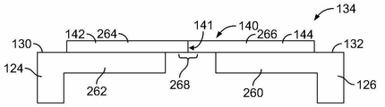
도 10은 예시적인 일 실시예에 따라 형성된 버스 바 조립체(134)의 단면도이다. 버스 바 조립체(134)의 판들(124, 126)과 버스 바(140)는 서로 별도로 제조되며 제조 동안 함께 연결된다. 버스 바(140)의 양의 단부(142)와 음의 단부(144)는, 예를 들어, 레이저 용접, 기타 용접, 또는 기타 부착 수단에 의해 양과 음의 판들(124, 126)에 각각 종단된다.10 is a cross-sectional view of a
예시적인 일 실시예에서, 음의 판(126)은 구리 블록(260)으로 제조된다. 양의 판(124)은 알루미늄 블록(262)으로 제조된다. 버스 바(140)는, 양의 단부(142)에서의 알루미늄 블록(264)과 음의 단부(144)에서의 구리 블록(266)을 포함하는 바이메탈 판으로 제조된다. 브리지(268)는, 알루미늄 블록(264)과 구리 블록(266) 간의 바이메탈 계면(141)에서 규정된다. 버스 바 조립체(134)는, 버스 바(140)를 형성하도록, 예를 들어, 클래딩, 레이저 용접, 초음파 용접에 의해 구리 블록(266)을 알루미늄 블록(264)에 종단함으로써, 또는 그 외에는 블록(264)을 블록(266)에 종단함으로써 제조된다. 버스 바(140)는 양과 음의 판들(124, 126)에 용접되고, 이때, 구리 블록(266)은 음의 판(126)에 용접되고, 알루미늄 블록(264)은 양의 판(124)에 용접된다. 양과 음의 셀 단자 판들(124, 126) 간에 바이메탈 구조를 이용함으로써, 아연 도금을 감소시키거나 제거할 수 있다.In one exemplary embodiment, the
도 11은 예시적인 일 실시예에 따라 형성된 버스 바 조립체(134)의 단면도이다. 버스 바 조립체(134)의 판들(124, 126)과 버스 바(140)는 서로 별도로 제조되며 제조 동안 함께 연결된다. 버스 바(140)의 양의 단부(142)와 음의 단부(144)는, 예를 들어, 레이저 용접, 기타 용접, 또는 기타 부착 수단에 의해 양과 음의 판들(124, 126)에 각각 종단된다.11 is a cross-sectional view of a
예시적인 일 실시예에서, 음의 판(126)은 구리 블록(280)으로 제조된다. 양의 판(124)은 알루미늄 블록(282)으로 제조된다. 버스 바(140)는, 바(284)와 바(284)를 둘러싸는 코팅(286)을 포함하는 바이메탈 판으로 제조된다. 코팅(286)은 바(284)와는 다른 금속 물질이다. 코팅(286)은 아연 도금에 저항하는 갈바니 방식(galvanic protection)을 제공한다. 양과 음의 셀 단자 판들(124, 126) 간에 바이메탈 구조를 이용함으로써, 아연 도금을 감소시키거나 제거할 수 있다.In an exemplary embodiment, the
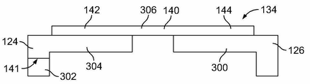
도 12는 예시적인 일 실시예에 따라 형성된 버스 바 조립체(134)의 단면도이다. 버스 바 조립체(134)의 판들(124, 126)과 버스 바(140)는 서로 별도로 제조되며 제조 동안 함께 연결된다. 버스 바(140)의 양의 단부(142)와 음의 단부(144)는, 예를 들어, 레이저 용접, 기타 용접, 또는 기타 부착 수단에 의해 양의 판(124)과 음의 판(126)에 각각 종단된다.12 is a cross-sectional view of a
예시적인 일 실시예에서, 음의 판(126)은 구리 블록(300)으로 제조된다. 양의 판(124)은, 바이메탈 계면(141)에서 접하는 알루미늄 블록(302)과 구리 블록(304)을 포함하는 바이메탈 판이다. 버스 바(140)는 구리 물질의 블록 또는 바(306)이다. 버스 바 조립체(134)는, 양의 판(124)을 형성하도록, 예를 들어, 클래딩, 레이저 용접, 초음파 용접에 의해 구리 블록(304)을 알루미늄 블록(302)에 종단함으로써, 또는 그 외에는 블록(304)을 블록(302)에 종단함으로써 제조된다. 바(306)는, 예를 들어, 레이저 용접 또는 기타 적절한 수단에 의해 양의 판(124)의 구리인 양의 블록(304)에 종단된다. 바(306)는, 예를 들어, 레이저 용접 또는 기타 적절한 수단에 의해 음의 판(126)에 종단된다. 따라서, 버스 바(140)는 양과 음의 판들(124, 126)에 용접된다. 양과 음의 셀 단자 판들(124, 126) 간에 바이메탈 구조를 이용함으로써, 아연 도금을 감소시키거나 제거할 수 있다.In an exemplary embodiment,
대체 실시예에서, 양의 판(124)은 마찬가지 방식으로 바이메탈 판으로서 제조될 수 있고, 이 경우, 버스 바는 구리 바라기보다는 알루미늄 바이다. 예를 들어, 양의 판(124)은 상부에서의 알루미늄 블록과 하부에서의 알루미늄 블록을 포함할 수 있다.In alternate embodiments, the
위 설명은 예시하기 위한 것이며 제한적이지 않다는 점을 이해하기 바란다. 예를 들어, 전술한 실시예들(및/또는 이들의 양태들)은 서로 조합하여 사용될 수 있다. 또한, 본 발명의 범위로부터 벗어나지 않고서 특정한 상황이나 물질을 본 발명의 교시에 맞추도록 많은 수정을 행할 수 있다. 치수, 물질의 유형, 다양한 구성요소들의 배향, 및 본 명세서에서 설명하는 다양한 구성요소들의 개수와 위치는, 일부 실시예들의 파라미터들을 규정하려는 것이며, 결코 한정적인 것이 아니며 예시적인 실시예들일 뿐이다. 청구범위의 사상과 범위 내의 다른 많은 실시예들과 수정예들은, 위 설명을 읽는 통상의 기술자에겐 명백할 것이다.It is to be understood that the above description is intended to be illustrative and not restrictive. For example, the above-described embodiments (and / or aspects thereof) may be used in combination with one another. In addition, many modifications may be made to adapt a particular situation or material to the teachings of the invention without departing from its scope. The dimensions, the type of material, the orientation of the various components, and the number and location of the various components described herein are intended to define the parameters of some embodiments, and are in no way limiting and are exemplary embodiments only. Many other embodiments and modifications within the spirit and scope of the claims will be apparent to those of ordinary skill in the art upon reading the foregoing description.
Claims (10)
평평한 패드(130)를 갖는 양(positive)의 배터리 셀 단자(120);
평평한 패드(132)를 갖는 음(negative)의 배터리 셀 단자(122); 및
음의 단부(144)와 양의 단부(142)를 갖는 버스 바(140)를 포함하고,
상기 버스 바는, 상기 양의 단부에서 상기 양의 배터리 셀 단자에 부착되고 상기 음의 단부에서 상기 음의 배터리 셀 단자에 부착되고,
상기 양의 배터리 셀 단자, 상기 음의 배터리 셀 단자, 및 상기 버스 바 중 적어도 하나는 바이메탈 계면(bimetal interface; 141)을 갖는, 바이메탈 버스 바 조립체(134).As a bimetal buss bar assembly,
A positive battery cell terminal 120 having a flat pad 130;
A negative battery cell terminal 122 having a flat pad 132; And
And a bus bar (140) having a negative end (144) and a positive end (142)
The bus bar is attached to the positive battery cell terminal at the positive end and to the negative battery cell terminal at the negative end,
Wherein at least one of the positive battery cell terminal, the negative battery cell terminal, and the bus bar has a bimetal interface (141).
Applications Claiming Priority (9)
| Application Number | Priority Date | Filing Date | Title |
|---|---|---|---|
| US201261649820P | 2012-05-21 | 2012-05-21 | |
| US61/649,820 | 2012-05-21 | ||
| US201261734674P | 2012-12-07 | 2012-12-07 | |
| US61/734,674 | 2012-12-07 | ||
| US201261735310P | 2012-12-10 | 2012-12-10 | |
| US61/735,310 | 2012-12-10 | ||
| US13/839,567 US9318734B2 (en) | 2012-05-21 | 2013-03-15 | Bimetal buss bar assembly |
| US13/839,567 | 2013-03-15 | ||
| PCT/US2013/040743 WO2013176914A1 (en) | 2012-05-21 | 2013-05-13 | Bimetal buss bar assembly |
Related Child Applications (1)
| Application Number | Title | Priority Date | Filing Date |
|---|---|---|---|
| KR1020167018195A Division KR20160086418A (en) | 2012-05-21 | 2013-05-13 | Bimetal buss bar assembly |
Publications (1)
| Publication Number | Publication Date |
|---|---|
| KR20150003864A true KR20150003864A (en) | 2015-01-09 |
Family
ID=49580371
Family Applications (2)
| Application Number | Title | Priority Date | Filing Date |
|---|---|---|---|
| KR1020147032786A KR20150003864A (en) | 2012-05-21 | 2013-05-13 | Bimetal buss bar assembly |
| KR1020167018195A KR20160086418A (en) | 2012-05-21 | 2013-05-13 | Bimetal buss bar assembly |
Family Applications After (1)
| Application Number | Title | Priority Date | Filing Date |
|---|---|---|---|
| KR1020167018195A KR20160086418A (en) | 2012-05-21 | 2013-05-13 | Bimetal buss bar assembly |
Country Status (6)
| Country | Link |
|---|---|
| US (1) | US9318734B2 (en) |
| EP (1) | EP2852991A1 (en) |
| JP (1) | JP2015517728A (en) |
| KR (2) | KR20150003864A (en) |
| CN (1) | CN104321906A (en) |
| WO (1) | WO2013176914A1 (en) |
Cited By (1)
| Publication number | Priority date | Publication date | Assignee | Title |
|---|---|---|---|---|
| US10573874B2 (en) | 2015-08-21 | 2020-02-25 | Dae San Electronics Co., Ltd. | Method of manufacturing electronical connection means |
Families Citing this family (29)
| Publication number | Priority date | Publication date | Assignee | Title |
|---|---|---|---|---|
| DE102013112060A1 (en) * | 2013-11-01 | 2015-05-07 | Johnson Controls Advanced Power Solutions Gmbh | Electrochemical accumulator |
| US9917291B2 (en) * | 2015-05-05 | 2018-03-13 | Johnson Controls Technology Company | Welding process for a battery module |
| US10407004B2 (en) * | 2015-06-30 | 2019-09-10 | Faraday & Future Inc. | Solid state switch for vehicle energy-storage systems |
| US10826042B2 (en) | 2015-06-30 | 2020-11-03 | Faraday & Future Inc. | Current carrier for vehicle energy-storage systems |
| US20170005303A1 (en) | 2015-06-30 | 2017-01-05 | Faraday&Future Inc. | Vehicle Energy-Storage System |
| US9692095B2 (en) * | 2015-06-30 | 2017-06-27 | Faraday&Future Inc. | Fully-submerged battery cells for vehicle energy-storage systems |
| US10505163B2 (en) | 2015-06-30 | 2019-12-10 | Faraday & Future Inc. | Heat exchanger for vehicle energy-storage systems |
| US11258104B2 (en) | 2015-06-30 | 2022-02-22 | Faraday & Future Inc. | Vehicle energy-storage systems |
| WO2017004078A1 (en) * | 2015-06-30 | 2017-01-05 | Faraday&Future Inc. | Vehicle energy-storage systems |
| US9692096B2 (en) * | 2015-06-30 | 2017-06-27 | Faraday&Future Inc. | Partially-submerged battery cells for vehicle energy-storage systems |
| CN114639908A (en) * | 2015-06-30 | 2022-06-17 | 法拉第未来公司 | Vehicle energy storage system |
| US11108100B2 (en) | 2015-06-30 | 2021-08-31 | Faraday & Future Inc. | Battery module for vehicle energy-storage systems |
| US9995535B2 (en) | 2015-06-30 | 2018-06-12 | Faraday&Future Inc. | Heat pipe for vehicle energy-storage systems |
| JP6590212B2 (en) * | 2015-07-17 | 2019-10-16 | 株式会社オートネットワーク技術研究所 | Wiring module and power storage module |
| CN106025162B (en) * | 2016-06-30 | 2019-11-08 | 上海捷新动力电池系统有限公司 | A kind of soft package battery module connection structure |
| US10333129B2 (en) * | 2017-01-26 | 2019-06-25 | Te Connectivity Corporation | Buss bar assembly for a battery system |
| DE102017201739B4 (en) | 2017-02-03 | 2021-02-25 | Volkswagen Aktiengesellschaft | Arrangement and method for making electrical contact with cell modules and batteries with such an arrangement |
| WO2018168802A1 (en) | 2017-03-15 | 2018-09-20 | 株式会社Gsユアサ | Electricity storage device |
| US10787084B2 (en) * | 2017-03-17 | 2020-09-29 | Ford Global Technologies, Llc | Busbar with dissimilar materials |
| KR102209773B1 (en) | 2017-05-29 | 2021-01-28 | 주식회사 엘지화학 | Battery Module |
| US11688900B2 (en) * | 2017-06-01 | 2023-06-27 | Clarios Advanced Solutions Gmbh | Energy storage module cell assembly including pouch cell, compression element, thermal plate, and cell frame, and method for assembling the same |
| CN108198988B (en) * | 2018-01-02 | 2021-08-06 | 华霆(合肥)动力技术有限公司 | Battery welding structure and method for welding and repairing positive electrode lug |
| DE102018112313A1 (en) * | 2018-05-23 | 2019-11-28 | Auto-Kabel Management Gmbh | Battery cells connector |
| KR102255487B1 (en) | 2018-07-03 | 2021-07-21 | 주식회사 엘지에너지솔루션 | Battery module, battery pack comprising the battery module and vehicle comprising the battery pack |
| KR102340419B1 (en) | 2018-09-21 | 2021-12-15 | 주식회사 엘지에너지솔루션 | Battery Module Having Module Bus-bar |
| US10964988B2 (en) | 2018-10-08 | 2021-03-30 | Ford Global Technologies, Llc | Fusible bimetallic bus bars for battery arrays |
| CN112889180B (en) * | 2018-10-31 | 2024-01-23 | 日本汽车能源株式会社 | Battery module |
| DE112020000459T5 (en) | 2019-01-21 | 2021-11-25 | Royal Precision Products, Llc | POWER DISTRIBUTION ARRANGEMENT WITH SCREWLESS BUSBAR SYSTEM |
| CN114788112A (en) | 2019-09-09 | 2022-07-22 | 伊顿智能动力有限公司 | Electrical bus and method for manufacturing the same |
Family Cites Families (8)
| Publication number | Priority date | Publication date | Assignee | Title |
|---|---|---|---|---|
| JP2002151045A (en) * | 2000-11-10 | 2002-05-24 | Honda Motor Co Ltd | Bus bar for battery module and battery module |
| JP2007134233A (en) * | 2005-11-11 | 2007-05-31 | Toyota Motor Corp | Battery terminal structure |
| US8257855B2 (en) | 2009-01-12 | 2012-09-04 | A123 Systems, Inc. | Prismatic battery module with scalable architecture |
| TW201042859A (en) | 2009-02-02 | 2010-12-01 | Gs Yuasa Corp | Electrode-connecting conductor, battery pack and manufacturing method of battery pack |
| US9024572B2 (en) * | 2009-03-31 | 2015-05-05 | Sanyo Electric Co., Ltd. | Battery module, battery system and electric vehicle |
| US9196890B2 (en) * | 2009-10-05 | 2015-11-24 | Samsung Sdi Co., Ltd. | Battery module with welded portion between terminals |
| WO2013065523A1 (en) * | 2011-10-31 | 2013-05-10 | 三洋電機株式会社 | Cell assembly, and rectangular secondary cell for use in cell assembly |
| US9105912B2 (en) * | 2012-05-21 | 2015-08-11 | Tyco Electronics Corporation | Boltless battery cell connection |
-
2013
- 2013-03-15 US US13/839,567 patent/US9318734B2/en active Active
- 2013-05-13 JP JP2015514049A patent/JP2015517728A/en active Pending
- 2013-05-13 KR KR1020147032786A patent/KR20150003864A/en active Application Filing
- 2013-05-13 KR KR1020167018195A patent/KR20160086418A/en not_active Application Discontinuation
- 2013-05-13 EP EP13727427.0A patent/EP2852991A1/en not_active Withdrawn
- 2013-05-13 CN CN201380026761.8A patent/CN104321906A/en active Pending
- 2013-05-13 WO PCT/US2013/040743 patent/WO2013176914A1/en active Application Filing
Cited By (1)
| Publication number | Priority date | Publication date | Assignee | Title |
|---|---|---|---|---|
| US10573874B2 (en) | 2015-08-21 | 2020-02-25 | Dae San Electronics Co., Ltd. | Method of manufacturing electronical connection means |
Also Published As
| Publication number | Publication date |
|---|---|
| EP2852991A1 (en) | 2015-04-01 |
| US20130306353A1 (en) | 2013-11-21 |
| CN104321906A (en) | 2015-01-28 |
| US9318734B2 (en) | 2016-04-19 |
| WO2013176914A1 (en) | 2013-11-28 |
| KR20160086418A (en) | 2016-07-19 |
| JP2015517728A (en) | 2015-06-22 |
Similar Documents
| Publication | Publication Date | Title |
|---|---|---|
| KR20150003864A (en) | Bimetal buss bar assembly | |
| EP2416436B1 (en) | Voltage-detecting member, and battery module including same | |
| US9640790B2 (en) | Middle or large-sized battery module | |
| US7892669B2 (en) | Middle or large-sized battery module | |
| US7875378B2 (en) | Voltage sensing member and battery module employed with the same | |
| CN106953060B (en) | Bus bar module and bus bar module manufacturing method | |
| KR101264550B1 (en) | Battery Pack | |
| JP6507136B2 (en) | Battery pack | |
| EP2887427A1 (en) | Battery module with bus-bar holder | |
| US20110269001A1 (en) | Assembled battery | |
| CN106605317B (en) | Assembled battery | |
| JP6051753B2 (en) | Power storage module | |
| US9837687B2 (en) | Battery module | |
| CN102804447A (en) | Battery module including sensing members with novel structure | |
| KR20150003866A (en) | Boltless battery cell connection | |
| JP2013093307A (en) | Wiring module for cell | |
| KR20150104733A (en) | Battery Module Having Voltage Sensing Member with Receptacle Structure | |
| US9088042B2 (en) | Battery pack having elongate curved lead plates | |
| CN111316464A (en) | Electrochemical cell stack, energy storage module and method for assembling same | |
| EP3754747B1 (en) | Bus bar module | |
| US20170222289A1 (en) | Assembly module comprising electrochemical cells received by lugs and connecting clips | |
| KR101741704B1 (en) | A Connecting Terminal Unit of Battery Pack and A Method for Connecting Battery Pack | |
| KR20130104844A (en) | Battery pack | |
| CN217086784U (en) | Battery module and battery pack | |
| JP4697100B2 (en) | Battery module |
Legal Events
| Date | Code | Title | Description |
|---|---|---|---|
| A201 | Request for examination | ||
| E902 | Notification of reason for refusal | ||
| AMND | Amendment | ||
| AMND | Amendment | ||
| A107 | Divisional application of patent |