KR20150003866A - Boltless battery cell connection - Google Patents
Boltless battery cell connection Download PDFInfo
- Publication number
- KR20150003866A KR20150003866A KR1020147032796A KR20147032796A KR20150003866A KR 20150003866 A KR20150003866 A KR 20150003866A KR 1020147032796 A KR1020147032796 A KR 1020147032796A KR 20147032796 A KR20147032796 A KR 20147032796A KR 20150003866 A KR20150003866 A KR 20150003866A
- Authority
- KR
- South Korea
- Prior art keywords
- battery
- positive
- negative
- bus bars
- carrier
- Prior art date
Links
Images


Classifications
-
- H—ELECTRICITY
- H01—ELECTRIC ELEMENTS
- H01M—PROCESSES OR MEANS, e.g. BATTERIES, FOR THE DIRECT CONVERSION OF CHEMICAL ENERGY INTO ELECTRICAL ENERGY
- H01M50/00—Constructional details or processes of manufacture of the non-active parts of electrochemical cells other than fuel cells, e.g. hybrid cells
- H01M50/50—Current conducting connections for cells or batteries
- H01M50/502—Interconnectors for connecting terminals of adjacent batteries; Interconnectors for connecting cells outside a battery casing
- H01M50/503—Interconnectors for connecting terminals of adjacent batteries; Interconnectors for connecting cells outside a battery casing characterised by the shape of the interconnectors
-
- H—ELECTRICITY
- H01—ELECTRIC ELEMENTS
- H01M—PROCESSES OR MEANS, e.g. BATTERIES, FOR THE DIRECT CONVERSION OF CHEMICAL ENERGY INTO ELECTRICAL ENERGY
- H01M50/00—Constructional details or processes of manufacture of the non-active parts of electrochemical cells other than fuel cells, e.g. hybrid cells
- H01M50/50—Current conducting connections for cells or batteries
- H01M50/502—Interconnectors for connecting terminals of adjacent batteries; Interconnectors for connecting cells outside a battery casing
- H01M50/507—Interconnectors for connecting terminals of adjacent batteries; Interconnectors for connecting cells outside a battery casing comprising an arrangement of two or more busbars within a container structure, e.g. busbar modules
-
- H—ELECTRICITY
- H01—ELECTRIC ELEMENTS
- H01M—PROCESSES OR MEANS, e.g. BATTERIES, FOR THE DIRECT CONVERSION OF CHEMICAL ENERGY INTO ELECTRICAL ENERGY
- H01M50/00—Constructional details or processes of manufacture of the non-active parts of electrochemical cells other than fuel cells, e.g. hybrid cells
- H01M50/50—Current conducting connections for cells or batteries
- H01M50/502—Interconnectors for connecting terminals of adjacent batteries; Interconnectors for connecting cells outside a battery casing
- H01M50/521—Interconnectors for connecting terminals of adjacent batteries; Interconnectors for connecting cells outside a battery casing characterised by the material
- H01M50/522—Inorganic material
-
- H—ELECTRICITY
- H01—ELECTRIC ELEMENTS
- H01M—PROCESSES OR MEANS, e.g. BATTERIES, FOR THE DIRECT CONVERSION OF CHEMICAL ENERGY INTO ELECTRICAL ENERGY
- H01M50/00—Constructional details or processes of manufacture of the non-active parts of electrochemical cells other than fuel cells, e.g. hybrid cells
- H01M50/50—Current conducting connections for cells or batteries
- H01M50/531—Electrode connections inside a battery casing
-
- H—ELECTRICITY
- H01—ELECTRIC ELEMENTS
- H01M—PROCESSES OR MEANS, e.g. BATTERIES, FOR THE DIRECT CONVERSION OF CHEMICAL ENERGY INTO ELECTRICAL ENERGY
- H01M50/00—Constructional details or processes of manufacture of the non-active parts of electrochemical cells other than fuel cells, e.g. hybrid cells
- H01M50/50—Current conducting connections for cells or batteries
- H01M50/543—Terminals
- H01M50/547—Terminals characterised by the disposition of the terminals on the cells
- H01M50/55—Terminals characterised by the disposition of the terminals on the cells on the same side of the cell
-
- H—ELECTRICITY
- H01—ELECTRIC ELEMENTS
- H01M—PROCESSES OR MEANS, e.g. BATTERIES, FOR THE DIRECT CONVERSION OF CHEMICAL ENERGY INTO ELECTRICAL ENERGY
- H01M50/00—Constructional details or processes of manufacture of the non-active parts of electrochemical cells other than fuel cells, e.g. hybrid cells
- H01M50/50—Current conducting connections for cells or batteries
- H01M50/543—Terminals
- H01M50/552—Terminals characterised by their shape
- H01M50/553—Terminals adapted for prismatic, pouch or rectangular cells
-
- H—ELECTRICITY
- H01—ELECTRIC ELEMENTS
- H01M—PROCESSES OR MEANS, e.g. BATTERIES, FOR THE DIRECT CONVERSION OF CHEMICAL ENERGY INTO ELECTRICAL ENERGY
- H01M50/00—Constructional details or processes of manufacture of the non-active parts of electrochemical cells other than fuel cells, e.g. hybrid cells
- H01M50/50—Current conducting connections for cells or batteries
- H01M50/543—Terminals
- H01M50/564—Terminals characterised by their manufacturing process
- H01M50/566—Terminals characterised by their manufacturing process by welding, soldering or brazing
-
- H—ELECTRICITY
- H01—ELECTRIC ELEMENTS
- H01M—PROCESSES OR MEANS, e.g. BATTERIES, FOR THE DIRECT CONVERSION OF CHEMICAL ENERGY INTO ELECTRICAL ENERGY
- H01M50/00—Constructional details or processes of manufacture of the non-active parts of electrochemical cells other than fuel cells, e.g. hybrid cells
- H01M50/50—Current conducting connections for cells or batteries
- H01M50/569—Constructional details of current conducting connections for detecting conditions inside cells or batteries, e.g. details of voltage sensing terminals
-
- H—ELECTRICITY
- H01—ELECTRIC ELEMENTS
- H01R—ELECTRICALLY-CONDUCTIVE CONNECTIONS; STRUCTURAL ASSOCIATIONS OF A PLURALITY OF MUTUALLY-INSULATED ELECTRICAL CONNECTING ELEMENTS; COUPLING DEVICES; CURRENT COLLECTORS
- H01R4/00—Electrically-conductive connections between two or more conductive members in direct contact, i.e. touching one another; Means for effecting or maintaining such contact; Electrically-conductive connections having two or more spaced connecting locations for conductors and using contact members penetrating insulation
- H01R4/10—Electrically-conductive connections between two or more conductive members in direct contact, i.e. touching one another; Means for effecting or maintaining such contact; Electrically-conductive connections having two or more spaced connecting locations for conductors and using contact members penetrating insulation effected solely by twisting, wrapping, bending, crimping, or other permanent deformation
- H01R4/18—Electrically-conductive connections between two or more conductive members in direct contact, i.e. touching one another; Means for effecting or maintaining such contact; Electrically-conductive connections having two or more spaced connecting locations for conductors and using contact members penetrating insulation effected solely by twisting, wrapping, bending, crimping, or other permanent deformation by crimping
- H01R4/183—Electrically-conductive connections between two or more conductive members in direct contact, i.e. touching one another; Means for effecting or maintaining such contact; Electrically-conductive connections having two or more spaced connecting locations for conductors and using contact members penetrating insulation effected solely by twisting, wrapping, bending, crimping, or other permanent deformation by crimping for cylindrical elongated bodies, e.g. cables having circular cross-section
- H01R4/184—Electrically-conductive connections between two or more conductive members in direct contact, i.e. touching one another; Means for effecting or maintaining such contact; Electrically-conductive connections having two or more spaced connecting locations for conductors and using contact members penetrating insulation effected solely by twisting, wrapping, bending, crimping, or other permanent deformation by crimping for cylindrical elongated bodies, e.g. cables having circular cross-section comprising a U-shaped wire-receiving portion
- H01R4/185—Electrically-conductive connections between two or more conductive members in direct contact, i.e. touching one another; Means for effecting or maintaining such contact; Electrically-conductive connections having two or more spaced connecting locations for conductors and using contact members penetrating insulation effected solely by twisting, wrapping, bending, crimping, or other permanent deformation by crimping for cylindrical elongated bodies, e.g. cables having circular cross-section comprising a U-shaped wire-receiving portion combined with a U-shaped insulation-receiving portion
-
- H—ELECTRICITY
- H01—ELECTRIC ELEMENTS
- H01M—PROCESSES OR MEANS, e.g. BATTERIES, FOR THE DIRECT CONVERSION OF CHEMICAL ENERGY INTO ELECTRICAL ENERGY
- H01M2220/00—Batteries for particular applications
- H01M2220/20—Batteries in motive systems, e.g. vehicle, ship, plane
-
- Y—GENERAL TAGGING OF NEW TECHNOLOGICAL DEVELOPMENTS; GENERAL TAGGING OF CROSS-SECTIONAL TECHNOLOGIES SPANNING OVER SEVERAL SECTIONS OF THE IPC; TECHNICAL SUBJECTS COVERED BY FORMER USPC CROSS-REFERENCE ART COLLECTIONS [XRACs] AND DIGESTS
- Y02—TECHNOLOGIES OR APPLICATIONS FOR MITIGATION OR ADAPTATION AGAINST CLIMATE CHANGE
- Y02E—REDUCTION OF GREENHOUSE GAS [GHG] EMISSIONS, RELATED TO ENERGY GENERATION, TRANSMISSION OR DISTRIBUTION
- Y02E60/00—Enabling technologies; Technologies with a potential or indirect contribution to GHG emissions mitigation
- Y02E60/10—Energy storage using batteries
Landscapes
- Chemical & Material Sciences (AREA)
- Chemical Kinetics & Catalysis (AREA)
- Electrochemistry (AREA)
- General Chemical & Material Sciences (AREA)
- Engineering & Computer Science (AREA)
- Manufacturing & Machinery (AREA)
- Inorganic Chemistry (AREA)
- Connection Of Batteries Or Terminals (AREA)
- Battery Mounting, Suspending (AREA)
Abstract
배터리 팩(100)은, 양과 음의 셀 단자들(120, 122)을 각각 갖는 복수의 배터리 셀(102), 및 복수의 배터리 셀 위로 장착되고 복수의 배터리 셀에 걸쳐 이어지는 캐리어(230)를 포함한다. 캐리어는, 양과 음의 셀 단자들을 노출시키는 개구들(236, 238)이 있는 트레이들(232)을 갖는다. 복수의 버스 바(150)는 대응하는 트레이들 내에 수용된다. 버스 바들의 각각은, 대응하는 개구를 통해 대응하는 배터리 셀의 양의 셀 단자에 레이저 용접된 양의 판(152) 및 대응하는 개구를 통해 다른 배터리 셀의 음의 셀 단자에 레이저 용접된 음의 판(154)을 구비한다. 버스 바들은 바이메탈 버스 바들일 수 있다.The battery pack 100 includes a plurality of battery cells 102 each having positive and negative cell terminals 120 and 122 and a carrier 230 mounted on the plurality of battery cells and extending over a plurality of battery cells do. The carrier has trays 232 with openings 236, 238 exposing positive and negative cell terminals. A plurality of bus bars (150) are received in corresponding trays. Each of the bus bars has a positive plate 152 welded to the positive cell terminal of the corresponding battery cell through a corresponding opening and a negative plate 152 welded to the negative cell terminal of the other battery cell through the corresponding opening Plate 154 is provided. The bus bars may be bimetal bus bars.
Description
본 개시 내용은 일반적으로 배터리 모듈에 관한 것이다. 전기 차량 또는 하이브리드 차량용 배터리 모듈 등의 배터리 모듈은, 통상적으로, 배터리 모듈들을 형성하도록 함께 그룹화된 복수의 셀을 포함한다. 배터리 모듈들은 함께 연결되어 배터리 팩들을 형성한다. 셀들의 각각은 함께 전기적으로 연결되는 양의 셀 단자와 음의 셀 단자를 포함한다. 서로 다른 유형의 배터리 모듈들은 서로 다른 유형의 셀들을 사용하여 형성된다. 예를 들어, 한 유형의 배터리 모듈들은 파우치형 배터리 모듈이라 하고, 다른 한 유형의 배터리 모듈들은 프리즘형 배터리 모듈이라 하고, 제3 유형의 배터리 모듈들은 원통형 배터리 모듈이라 한다.The present disclosure relates generally to battery modules. Battery modules, such as battery modules for electric vehicles or hybrid vehicles, typically include a plurality of cells grouped together to form battery modules. The battery modules are connected together to form battery packs. Each of the cells includes a positive cell terminal and a negative cell terminal electrically connected together. Different types of battery modules are formed using different types of cells. For example, one type of battery module is referred to as a pouch type battery module, another type of battery module is referred to as a prismatic battery module, and a third type of battery module is referred to as a cylindrical battery module.
프리즘형 배터리 모듈에서는 함께 적층되는 프리즘형 배터리 셀들을 사용한다. 양의 셀 단자와 음의 셀 단자는 버스 바를 이용하여 연결된다. 양의 셀 단자와 음의 셀 단자는 통상적으로 스레드형 포스트(threaded post) 또는 볼트를 포함한다. 버스 바는 너트를 사용하여 포스트에 연결된다. 통상적인 배터리 모듈들은, 버스 바와 너트를 사용하여 각각 함께 연결되는 10개 이상의 배터리 셀을 포함한다. 문제는, 이러한 연결이 시간 소모적이라는 것이다.In a prismatic battery module, prismatic battery cells stacked together are used. Positive cell terminals and negative cell terminals are connected using a bus bar. Positive and negative cell terminals typically include threaded posts or bolts. The bus bar is connected to the post using a nut. Typical battery modules include ten or more battery cells, each connected together using a bus bar and a nut. The problem is that this connection is time consuming.
해결책은, 양과 음의 셀 단자들을 각각 갖는 복수의 배터리 셀 및 복수의 배터리 셀 위에 장착되며 복수의 배터리 셀에 걸쳐 이어지는 캐리어를 포함하는, 본 명세서에서 개시하는 바와 같은 배터리 팩을 제공하는 것이다. 캐리어는, 양과 음의 셀 단자들을 노출시키는 개구들이 있는 트레이들을 구비한다. 복수의 버스 바가 대응하는 트레이들 내에 수용된다. 버스 바들의 각각은, 대응하는 개구를 통해 대응하는 배터리 셀의 양의 셀 단자에 레이저 용접된 양의 판 및 대응하는 개구를 통해 다른 배터리 셀의 음의 셀 단자에 레이저 용접된 음의 판을 구비한다. 버스 바들은 바이메탈 버스 바들일 수 있다.The solution is to provide a battery pack as disclosed herein comprising a plurality of battery cells each having positive and negative cell terminals and a carrier mounted over the plurality of battery cells and extending across the plurality of battery cells. The carrier has trays with openings that expose positive and negative cell terminals. A plurality of bus bars are accommodated in the corresponding trays. Each of the bus bars has a negative plate laser welded to the positive cell terminal of the corresponding battery cell through a corresponding opening and a negative plate laser welded to the negative cell terminal of the other battery cell through the corresponding opening do. The bus bars may be bimetal bus bars.
이제, 첨부 도면을 참조하여 본 발명을 예를 들어 설명한다.Now, the present invention will be described by way of example with reference to the accompanying drawings.
도 1은 예시적인 일 실시예에 따라 형성된 배터리 팩의 상부 사시도.
도 2는 예시적인 일 실시예에 따라 형성된 프리즘형 배터리 셀들 중 하나의 상부 사시도.
도 3은 예시적인 일 실시예에 따라 형성된 버스 바의 상부 사시도.
도 4는 예시적인 일 실시예에 따라 형성된 버스 바의 단면도.
도 5는 예시적인 일 실시예에 따라 형성된 버스 바의 단면도.
도 6은 예시적인 일 실시예에 따라 형성된 버스 바의 단면도.
도 7은 예시적인 일 실시예에 따라 형성된 버스 바의 단면도.
도 8은 예시적인 일 실시예에 따라 형성된 버스 바의 사시도.
도 9는 예시적인 일 실시예에 따라 형성된 버스 바의 사시도.
도 10은 예시적인 일 실시예에 따라 형성된 버스 바의 사시도.
도 11은 버스 바들을 위한 후면 캐리어를 도시하는 도.
도 12는 후면 커버를 도시하는 도.
도 13은 버스 바들을 위한 정면 캐리어를 도시하는 도.
도 14는 정면 커버를 도시하는 도.
도 15는 배터리 모듈의 일부를 도시하는 도.
도 16은 배터리 모듈의 다른 일부를 도시하는 도.
도 17은 예시적인 일 실시예에 따라 형성된 음의 배터리 단자의 사시도.
도 18은 암 커넥터(female connector)를 도시하는 도.
도 19는 음의 배터리 단자에 정합된 암 커넥터를 도시하는 도.
도 20은 양의 배터리 단자를 도시하는 도.
도 21은 양의 배터리 단자를 도시하는 도.
도 22는 양의 배터리 단자에 정합된 암 커넥터를 도시하는 도.
도 23은 배터리 모듈의 또 다른 일부를 도시하는 도.
도 24는 모듈간 암 커넥터(module-to-module female connector)의 사시도.
도 25는 예시적인 일 실시예에 따라 형성된 서미스터의 사시도.
도 26은 인접하는 배터리 셀들 사이에 로딩된 서미스터를 도시하는 도.
도 27은 배터리 팩의 예시적인 조립 방법을 도시하는 도.1 is a top perspective view of a battery pack formed in accordance with an exemplary embodiment;
Figure 2 is a top perspective view of one of the prismatic battery cells formed in accordance with an exemplary embodiment;
3 is a top perspective view of a bus bar formed in accordance with an exemplary embodiment;
4 is a cross-sectional view of a bus bar formed in accordance with an exemplary embodiment;
5 is a cross-sectional view of a bus bar formed in accordance with an exemplary embodiment;
6 is a cross-sectional view of a bus bar formed in accordance with an exemplary embodiment;
7 is a cross-sectional view of a bus bar formed in accordance with an exemplary embodiment;
8 is a perspective view of a bus bar formed in accordance with an exemplary embodiment;
9 is a perspective view of a bus bar formed in accordance with an exemplary embodiment;
10 is a perspective view of a bus bar formed in accordance with an exemplary embodiment;
11 is a view showing a rear carrier for bus bars;
12 is a view showing a rear cover.
Figure 13 shows a front carrier for bus bars;
14 is a view showing a front cover;
15 is a view showing a part of a battery module;
16 is a view showing another part of the battery module;
17 is a perspective view of a negative battery terminal formed in accordance with an exemplary embodiment;
18 is a view showing a female connector;
19 is a view showing a female connector matched to a negative battery terminal;
20 is a view showing a positive battery terminal;
21 is a view showing a positive battery terminal;
22 shows a female connector matched to a positive battery terminal;
23 is a view showing another part of the battery module.
24 is a perspective view of a module-to-module female connector;
25 is a perspective view of a thermistor formed in accordance with an exemplary embodiment;
26 is a view showing a thermistor loaded between adjacent battery cells;
27 is a view showing an exemplary assembling method of the battery pack.
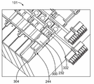
도 1은 예시적인 일 실시예에 따라 형성된 배터리 팩(100)의 상부 사시도이다. 배터리 팩(100)은 함께 적층된 복수의 배터리 모듈(101)을 포함한다. 배터리 팩(100)은, 전기 차량 또는 하이브리드 전기 차량 등의 차량의 배터리 시스템의 일부로서 사용될 수 있다. 대체 실시예들에서, 배터리 팩(100)은 다른 응용 분야들에서 사용될 수도 있다.1 is a top perspective view of a
각 배터리 모듈(101)은 복수의 프리즘형 배터리 셀(102)을 포함한다. 프리즘형 배터리 셀들(102)은, 적층 구성으로 나란히 배열되어 배터리 모듈(101)을 형성한다. 선택 사항으로, 배터리 모듈(101)은 프리즘형 배터리 셀들(102)을 유지하는 케이스 또는 기타 하우징을 포함할 수도 있다. 프리즘형 배터리 셀들(102)의 상부에 배터리 커버를 제공할 수 있다. 배터리 커버는 프리즘형 배터리 셀들(102)의 각각을 커버할 수 있다.Each
각 배터리 모듈(101)은 양의 배터리 단자(106)와 음의 배터리 단자(108)를 포함한다. 단자들(106, 108)은 외부 전력 케이블에 결합되도록 구성되거나 또는 대안으로 다른 배터리 모듈(101)의 배터리 셀 단자들에 버스 결합(buss)될 수 있다. 예시적인 일 실시예에서, 배터리 단자들(106, 108)은 빠른 연결형 커넥터들을 사용하여 연결된다.Each
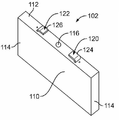
도 2는 예시적인 실시예에 따라 형성된 프리즘형 배터리 셀들(102) 중 하나의 상부 사시도이다. 프리즘형 배터리 셀(102)은 상부(112)와 측벽들(114)을 갖는 셀 하우징(110)을 포함한다. 예시한 실시예에서, 셀 하우징(110)은 4개의 측벽(114)을 갖는 박스 형상이다. 배터리 셀(102)은 상부(112) 상에 가스 압력 밸브(116)를 갖는다.2 is a top perspective view of one of the
배터리 셀(102)은 양의 배터리 셀 단자(120)와 음의 배터리 셀 단자(122)를 포함한다. 예시적인 일 실시예에서, 양의 배터리 셀 단자(120)는 알루미늄이고, 음의 배터리 셀 단자(122)는 구리이다. 양의 배터리 셀 단자(120)는, 배터리 셀(102)을 위한 연결 계면으로서 사용되는, 상부(112)로부터 연장되는 포스트(124)를 갖는다. 예시한 실시예에서, 포스트(124)는 연결 계면을 규정하는 상면을 갖는 평평한 패드를 포함한다. 음의 배터리 셀 단자(122)는, 배터리 셀(102)을 위한 연결 계면으로서 사용되는, 상부(112)로부터 연장되는 포스트(126)를 갖는다. 예시한 실시예에서, 포스트(126)는 연결 계면을 규정하는 상면을 갖는 평평한 패드를 포함한다. The
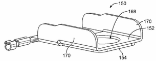
도 3은 예시적인 일 실시예에 따라 형성된 버스 바(150)의 상부 사시도이다. 버스 바(150)는, (도 2에 도시한) 인접하는 프리즘형 배터리 셀들(102)의 배터리 셀 단자들을 전기적으로 연결하는 데 사용된다. 버스 바(150)는, 양과 음의 셀 단자들(예를 들어, 알루미늄과 구리 셀 단자들) 모두에 연결될 때 아연 도금화(galvanizing)를 감소시키거나 제거함으로써 아연 도금 방지(galvanic protection)를 제공한다.FIG. 3 is a top perspective view of a
버스 바(150)는 양의 판(152)과 음의 판(154)을 포함한다. 양의 판(152)은 하나의 배터리 셀(102)의 (도 2에 도시한) 대응하는 양의 셀 단자(120)에 종단되도록 구성되고, 음의 판(154)은 인접하는 배터리 셀(102)의 (도 2에 도시한) 대응하는 음의 셀 단자(122)에 종단되도록 구성된다. 예시적인 일 실시예에서, 양과 음의 판들(152, 154)은 개별적으로 제조되고, 초음파 용접, 클래딩, 또는 기타 공정 등에 의해 함께 결합된다. 대안으로, 양과 음의 판들(152, 154)은 일체 형성될 수도 있다. 선택 사항으로, 양 및/또는 음의 판들(152, 154)을 도금할 수 있다. 양과 음의 판들(152, 154)은 임의의 두께와 형상을 가질 수 있다. 두께와 형상은 서로 다를 수 있다. 선택 사항으로, 64% ICAS 알루미늄 등의 고 농도 알루미늄을 사용할 수 있다. 양의 판(152)의 크기와 형상은, 버스 바(150)에 걸쳐 음의 판(154)과 유사하거나 균등한 저항을 갖도록 선택될 수 있다.The
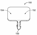
버스 바(150)는 음의 판(154)으로부터 연장되는 전압 감지 컨택트(156)를 포함한다. 예시한 실시예에서, 전압 감지 컨택트(156)는 전압 감지 시스템의 와이어를 수용하도록 구성된 크림프 배럴(crimp barrel)을 구성한다. 크림핑은, 정확하고 신뢰성 있는 감지를 위해 와이어와의 신뢰성 있는 연결을 제공한다. 대체 실시예들에서는, 다른 유형의 컨택트를 제공하여, 절연 변위 컨택트, 스프링 컨택트, 핀, 소켓, 포크인 와이어 연결부, 용접 패드 등의 전압 감지 시스템의 대응하는 부품에 연결할 수 있다. 전압 감지 와이어는, 대체 실시예들에서, 예를 들어, 용접, 솔더링, 도전성 접착제 등을 이용하여 버스 바(150)에 고정될 수 있다. 전압 감지 컨택트(156)의 위치는 특정 응용 분야에 따라 가변될 수 있다. 일부 실시예들은 전압 감지 컨택트(156)를 포함하지 않을 수도 있다. 대체 실시예들에서, 전압 감지 컨택트(156)는, 예를 들어, 솔더링, 용접, 잠궈짐으로써 음의 판(154)에 결합된 또는 그 외에는 음의 판(154)에 고정된 별도의 부품일 수 있다. 선택 사항으로, 전압 감지 컨택트(156)는 음의 판(154)과 함께 스탬핑되어 형성될 수 있다. 전압 감지 컨택트(156)는, 버스 바(150)에 걸친 전압을 측정함으로써 셀들의 전압을 감시하는 모듈 컨트롤러에 전기적으로 연결될 수 있다. 전압 감지 컨택트(156)는 대체 실시예들에서 양의 판(152)과 함께 형성될 수 있고 및/또는 양의 판으로부터 연장될 수 있다.The
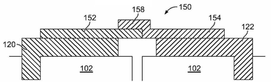
도 4는 예시적인 일 실시예에 따라 형성된 버스 바(150)의 단면도이다. 버스 바(150)는 양과 음의 판들(152, 154)을 초음파 용접함으로써 제조된다. 양의 판(152)은 알루미늄 물질로 제조된다. 음의 판(154)은 구리 물질로 제조된다. 바이메탈 브리지(158)는 양과 음의 판들(152, 154) 사이에 형성된다. 예시적인 일 실시예에서, 음의 판(154)의 일부는 양의 판(152)의 적어도 일부 위로 이어져 브리지(158)를 형성하지만, 양의 판(152)이 음의 판 위로 이어져 브리지를 형성할 수도 있다. 대체 실시예들에서. 브리지(158)는 양의 판(152)과 음의 판(154) 간의 바이메탈 계면을 규정한다. 바이메탈 계면은 양의 판(152)과 음의 판(154) 간의 연결을 보장하도록 넓은 표면적은 갖는다. 표면적은 브리지(158)의 중첩의 길이와 폭에 의해 규정된다. 예시적인 일 실시예에서, 길이와 폭 모두는 판들(152, 154)의 두께보다 크다. 선택 사항으로, 음의 판(154)의 약 10% 이상이 양의 판(152)과 중첩할 수 있다. 예시적인 일 실시예에서, 바이메탈 계면은 대략 평평하며 버스 바(150)의 면에 평행하다. 선택 사항으로, 양의 판(152)은 알루미늄 판일 수 있고, 음의 판(154)은 구리 판일 수 있다. 양의 판(152)은, 예를 들어, 클래딩 공정, 용접 공정, 또는 다른 종단 공정에 의해 음의 판(154)에 종단될 수 있다.4 is a cross-sectional view of a
버스 바(150)는, 양의 판(152)이 하나의 배터리 셀(102)의 양의 셀 단자(120)에 종단되고 음의 판(154)이 인접하는 배터리 셀(102)의 대응하는 음의 셀 단자(122)에 종단되도록, 인접하는 배터리 셀들(102) 간에 결합된다. 예시적인 일 실시예에서, 판들(152, 154)은 대응하는 단자들(120, 122)에 레이저 용접된다. 레이저 용접은, 너트와 스레딩 포스트에 대한 너트의 스레딩을 필요로 하지 않는다. 버스 바(150)는 레이저 용접에 의해 더욱 빠르게 종단될 수 있다. 레이저 용접은 버스 바(150)와 단자들(120, 122) 간의 양호한 전기적 연결, 예를 들어, 낮은 계면 저항을 갖는 계면을 제공한다.The
도 5는 예시적인 일 실시예에 따라 형성된 버스 바(150)의 단면도이다. 버스 바(150)는 양과 음의 판들(152, 154)을 클래딩함으로써 제조된다. 양의 판(152)은 알루미늄 물질로 제조된다. 음의 판(154)은 구리 물질로 제조된다. 바이메탈 브리지(158)는 클래딩 영역에서 양과 음의 판들(152, 154) 간에 형성된다.5 is a cross-sectional view of a
버스 바(150)는, 양의 판(152)이 하나의 배터리 셀(102)의 양의 셀 단자(120)에 종단되고 음의 판(154)이 인접하는 배터리 셀(102)의 대응하는 음의 셀 단자(122)에 종단되도록, 인접하는 배터리 셀들(102) 간에 결합된다. 예시적인 일 실시예에서, 판들(152, 154)은 대응하는 단자들(120, 122)에 레이저 용접된다.The
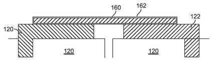
도 6은 예시적인 일 실시예에 따라 형성된 버스 바(150)의 단면도이다. 버스 바(150)는 코팅(162)이 코팅된 구리 판(160)으로 제조된다. 선택 사항으로, 코팅(162)은 판들(152, 154)에 고정될 수 있는 코팅일 수 있다. 예를 들어, 코팅(162)은 레이저 용접될 수 있다. 코팅(162)은 아연 도금에 저항하는 아연 도금 방지를 제공한다.6 is a cross-sectional view of a
버스 바(150)는, 양의 판(152)이 하나의 배터리 셀(102)의 양의 셀 단자(120)에 종단되고 음의 판(154)이 인접하는 배터리 셀(102)의 대응하는 음의 셀 단자(122)에 종단되도록, 인접하는 배터리 셀들(102) 간에 결합된다. 예시적인 일 실시예에서, 판들(152, 154)은 대응하는 단자들(120, 122)에 레이저 용접된다. 코팅(162)은 알루미늄 단자와 구리 단자 모두에 결합되도록 구성된 물질이다.The
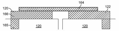
도 7은 예시적인 일 실시예에 따라 형성된 버스 바(150)의 단면도이다. 버스 바(150)는 구리 판(164)으로 제조된다. 양의 셀 단자(120)는, 알루미늄 포스트(165), 및 알루미늄 포스트(165)로부터 연장되는 바이메탈 포스트(166)를 포함한다. 바이메탈 포스트(166)는 알루미늄-구리 바이메탈일 수 있다.7 is a cross-sectional view of a
버스 바(150)는, 양의 판(152)이 하나의 배터리 셀(102)의 양의 셀 단자(120)에 종단되고 음의 판(154)이 인접하는 배터리 셀(102)의 대응하는 음의 셀 단자(122)에 종단되도록, 인접하는 배터리 셀들(102) 간에 결합된다. 예시적인 일 실시예에서, 판들(152, 1540은 대응하는 단자들(120, 122)에 레이저 용접된다.The
도 8은 예시적인 일 실시예에 따라 형성된 버스 바(150)의 사시도이다. 버스 바(150)는, 음의 판(154)을 통해 개구(168) 위로 양의 판(152)을 음의 판(154)에 초음파 용접함으로써 제조된다. 버스 바(150)는 버스 바(150)를 강화하도록 벽들(170)을 포함한다. 음의 판(154)의 형상은 양의 판(152)을 따른다. 양의 판(152)은 알루미늄 물질로 제조된다. 음의 판(154)은 구리 물질로 제조된다. 양과 음의 판들(152, 154)은, 양과 음의 판들 사이에 바이메탈 계면을 생성하여 아연 도금에 저항하는 아연 도금 방지를 제공하도록 초음파 용접된다.8 is a perspective view of a
도 9는 예시적인 일 실시예에 따라 형성된 버스 바(150)의 사시도이다. 버스 바(150)는 양과 음의 판들(152, 154)을 클래딩함으로써 제조된다. 양의 판(152)은 알루미늄 물질로 제조된다. 음의 판(154)은 구리 물질로 제조된다. 전압 감지 컨택트(156)는 음의 판(154)으로부터 연장된다.9 is a perspective view of a
도 10은 예시적인 일 실시예에 따라 형성된 버스 바(150)의 사시도이다. 버스 바(150)는 구리 시트로 제조된다. 버스 바(150)는, 니켈, 또는 다른 코팅을 포함할 수 있다. 양과 음의 판들(152, 154)은 구리 시트의 대향 단부들에 의해 규정된다. 전압 감지 컨택트(156)는, 구리 시트로부터 연장되며, 에지를 위치할 수 있으며, 예를 들어, 에지를 따라 중심에 위치할 수 있다.10 is a perspective view of a
도 11은 버스 바들(150)을 위한 후면 캐리어(200)를 도시한다. 후면 캐리어(200)는 (도 2에 도시한) 배터리 셀들(102)의 상부들(112)에 장착되도록 구성된다. 후면 캐리어(200)는 (도 3에 도시한) 대응하는 버스 바들(150)을 수용하는 복수의 트레이(202)를 포함한다. 트레이들(202)은 버스 바들(150)을 수용하는 리셉터클들 또는 포켓들(204)을 갖는다. 포켓들(204)은 버스 바들(150)을 수용하고 유지하기 위한 크기와 형상을 갖는다. 예를 들어, 버스 바들(150)은 간섭 끼워 맞춤에 의해 트레이들(202) 내에 유지될 수 있다. 돌출부들 또는 탭들(205)은 버스 바들(150)과 체결하여 버스 바들을 유지하도록 포켓들(204) 내로 연장될 수 있다.FIG. 11 shows a
트레이들(202)은 양과 음의 셀 단자들(120, 122)을 각각 노출시키는 개구들(206, 208)을 갖는다. 버스 바들(150)은 개구들(206, 208)을 통해 배터리 셀들(102)에 레이저 용접되거나 또는 그 외에는 배터리 셀들에 종단될 수 있다. 선택 사항으로, 버스 바들(150)의 일부가 배터리 셀들(102)과 체결하도록 개구들(206, 208) 내로 연장될 수 있고 및/또는 배터리 셀들의 일부가 버스 바들(150)과 체결하도록 개구들(206, 208) 내로 연장될 수 있다.The
트레이들(202)은 전압 감지 와이어 종단 영역들(210)을 갖는다. 전압 감지 와이어들은, (도 3에 도시한) 전압 감지 컨택트들(156)에 종단되도록 와이어 하니스(wire harness)로부터 영역들(210)로 경로 설정된다. 예시적인 일 실시예에서, 인접하는 트레이들(202)은, 배터리 셀들(102) 상에 위치 설정되도록 트레이들(202)과 버스 바들(150) 간의 상대적 이동을 허용하는 유연한 힌지들(212)에 의해 분리된다. 유연한 힌지들(212)은, 모든 인접하는 트레이들(202) 사이에, 또는 트레이들(202) 중 소정의 트레이들 사이에, 예를 들어, 모든 네 번째 트레이들(202) 사이에 제공될 수 있다. 후면 캐리어(200)는 플라스틱 물질 등의 유전 물질로 제조된다. 후면 캐리어(200)는 버스 바들(150)을 서로 그리고 버스 바들(150)을 둘러싸는 환경으로부터 전기적으로 분리한다.The
도 12는, 버스 바들(150) 위로 (도 11에 도시한) 후면 캐리어(200)에 결합되도록 구성된 후면 커버(220)를 도시한다. 후면 커버(220)는 플라스틱 물질 등의 유전 물질로 제조된다. 후면 커버(220)는 버스 바들(150)의 우연한 접촉을 방지한다. 선택 사항으로, 후면 커버(220)는, 예를 들어, 후면 캐리어(200)와 함께 성형되어 후면 캐리어(200)와 일체형일 수도 있다. 선택 사항으로, 후면 커버(220)는, 후면 캐리어(200) 상에 위치 설정되도록 후면 커버(220)의 섹션들의 상대적 이동을 허용하는 유연한 힌지들을 포함할 수 있다.12 illustrates a
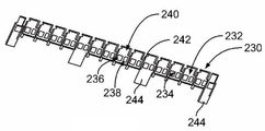
도 13은 버스 바들(150)을 위한 정면 캐리어(230)를 도시한다. 정면 캐리어(230)는 (도 2에 도시한) 배터리 셀들(102)의 상부들(112)에 장착되도록 구성된다. 정면 캐리어(230)는 플라스틱 물질 등의 유전 물질로 제조된다. 정면 캐리어(230)는 (도 3에 도시한) 버스 바들(150)의 우연한 접촉을 방지한다. 13 shows the
정면 캐리어(230)는 대응하는 버스 바들(150)을 수용하는 복수의 트레이(2332)를 포함한다. 트레이들(232)은 버스 바들(150)을 수용하는 리셉터클들 또는 포켓들(234)을 갖는다. 포켓들(234)은 버스 바들(150)을 수용하고 유지하기 위한 크기와 형상을 갖는다. 예를 들어, 버스 바들(150)은 간섭 끼워 맞춤에 의해 트레이들(232) 내에 유지될 수 있다. 돌출부들 또는 탭들은 버스 바들(150)과 체결하여 버스 바들을 유지하도록 포켓들(234) 내로 연장될 수 있다.The
트레이들(232)은 양과 음의 셀 단자들(120, 122)을 각각 노출시키는 개구들(236, 238)을 갖는다. 버스 바들(150)은 개구들(236, 238)을 통해 배터리 셀들(102)에 레이저 용접되거나 또는 그 외에는 배터리 셀들에 종단될 수 있다. 선택 사항으로, 버스 바들(150)의 일부가 배터리 셀들(102)과 체결하도록 개구들(236, 238) 내로 연장될 수 있고 및/또는 배터리 셀들(102)의 일부가 버스 바들(150)과 체결하도록 개구들(236, 238) 내로 연장될 수 있다.
트레이들(232)은 전압 감지 와이어 종단 영역들(240)을 갖는다. 전압 감지 와이어들은, (도 3에 도시한) 전압 감지 컨택트들(156)에 종단되도록 와이어 하니스로부터 영역들(240)로 경로 설정된다. 예시적인 일 실시예에서, 트레이들(232)은, 배터리 셀들(102) 상에 위치 설정되도록 트레이들(232)과 버스 바들(150) 간의 상대적 이동을 허용하는 유연한 힌지들(242)에 의해 분리된다. 유연한 힌지들(242)은, 모든 인접하는 트레이들(232) 사이에, 또는 트레이들(232) 중 소정의 트레이들 사이에, 예를 들어, 모든 네 번째 트레이들(202) 사이에 제공될 수 있다.
정면 트레이들(244)은 트레이들(232) 중 일부의 전방에 제공된다. 정면 트레이들(244)은 버스 바들(150)과 기타 부품들을 유지하기 위한 추가 공간을 제공한다. 선택 사항으로, 배터리 단자들은 정면 트레이들(2440 내의 대응하는 버스 바들에 종단될 수 있다. 모듈간 배터리 단자들은 정면 트레이들(244) 내에 수용될 수 있다. 양의 또는 음의 배터리 단자들은 정면 트레이들(244) 내에 수용될 수 있다. 전력 케이블들이 정면 트레이들(244) 내에 수용될 수 있다.
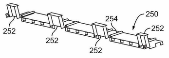
도 14는 버스 바들(150) 위로 (도 13에 도시한) 정면 캐리어(230)에 결합되도록 구성된 정면 커버(250)를 도시한다. 정면 커버(250)는 플라스틱 물질 등의 유전 물질로 제조된다. 정면 커버(250)는 버스 바들(150)의 우연한 접촉을 방지한다. 선택 사항으로, 정면 커버(250)는, 예를 들어, 정면 캐리어(230)와 함께 성형되어 정면 캐리어(230)와 일체형일 수도 있다. 14 illustrates a
정면 커버(250)는 리드들(lids; 252)을 포함한다. 리드들(252)은 정면 커버(250)의 정면 에지에 힌지 결합된다. 리드들(252)은 대응하는 정면 트레이들(244)과 정렬되도록 구성된다. 리드들(252)은 버스 바들(150) 및/또는 버스 바들(150)에 결합된 다른 부품들을 커버한다.The
예시적인 일 실시예에서, 정면 커버(250)는, 정면 캐리어(230) 상에 위치 설정되도록 정면 커버(250)의 섹션들의 상대적 이동을 허용하는 유연한 힌지들(254)을 포함한다.In an exemplary embodiment, the
도 15는 배터리 모듈(101)의 일부를 도시한다. 후면 캐리어(200)와 정면 캐리어(230)가 도시되어 있으며, 명확성을 위해 (도 12와 도 14에 도시한) 커버들(220, 250)은 제거되어 있다. 와이어 하니스들(260)은 와이어 하니스들의 단부들에서 커넥터들(262)과 함께 예시되어 있다. 와이어 하니스들(260)은, 대응하는 전압 감지 컨택트들(156)에 전기적으로 연결되며, 전압 감지 와이어 종단 영역들(210, 240)을 통과한다. 예를 들어, 와이어 하니스들(260)의 개별적인 전압 감지 와이어들(263)은 대응하는 전압 감지 컨택트들(156)에 연결될 수 있다.Fig. 15 shows a part of the
예시한 실시예에서, 전압 감지 컨택트들(156)은 전압 감지 와이어들(263)을 크림핑하기 위한 크림프 배럴들을 포함한다. 대안으로, 전압 감지 컨택트들(156)은, 전압 감지 와이어들(263)을 버스 바들(150)에 기계적으로 그리고 전기적으로 연결하도록 전압 감지 와이어들(263)의 단부들이 전압 감지 패드들에 용접되는 전압 감지 패드들 또는 용접 패드들을 포함할 수 있다.In the illustrated embodiment, the
버스 바들(150)은 포켓들(204, 234) 내에 위치한다. 양의 판(152)은 하나의 배터리 셀(102)과 정렬되도록 구성되고, 음의 판(154)은 인접하는 배터리 셀(102)과 정렬되도록 구성된다. 탭들(264)은 버스 바들(150)을 제 위치에서 유지한다. 전압 감지 컨택트들(156)은 전압 감지 와이어 종단 영역들(240) 내로 연장된다. 와이어 하니스들(260)로부터의 와이어들은, 컨택트들(156)에 종단되도록 전압 감지 와이어 종단 영역들(210, 240) 내로 경로 설정되도록 구성된다. 예시적인 일 실시예에서, 캐리어들(200, 230)은, 와이어 종단 영역들(210, 240) 내에서 와이어 하니스(260)를 유지하는 핑거들(266)을 포함한다.Bus bars 150 are located within
후면 캐리어(200) 및 대응하는 버스 바들(150)은 배터리 셀들(102) 상에 하나의 유닛으로서 위치되도록 구성된다. 이어서, 버스 바들(150)을 배터리 셀들(102)에 레이저 용접할 수 있고 또는 그 외에는 배터리 셀들에 기계적으로 그리고 전기적으로 연결할 수 있다. 마찬가지로, 정면 캐리어(230) 및 대응하는 버스 바들(150)도 배터리 셀들(102) 상에 하나의 유닛으로서 위치되도록 구성된다.The
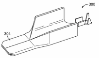
도 16은 배터리 모듈(101)의 다른 일부를 도시한다. 음의 배터리 단자(300)가 대응하는 트레이(232)와 정면 트레이(244) 내에 수용된 것으로 도시되어 있다. 음의 배터리 단자(300)는 전압 감지 컨택트(302)를 포함한다. 음의 배터리 단자(300)는 대응하는 부품에 빠르게 연결되도록 구성된 빠른 연결 단부(304)를 포함한다. 예시한 실시예에서, 빠른 연결 단부(304)는 대응하는 배터리 단자 내에 플러그 결합되도록 구성된 블레이드를 규정한다.16 shows another part of the
도 17은, 음의 배터리 단자(300)의 빠른 연결 단부(304)를 도시하는, 예시적인 일 실시예에 따라 형성된 음의 배터리 단자(300)의 사시도이다. 음의 배터리 단자(300)는 스탬핑되어 형성될 수 있다. 음의 배터리 단자(300)는 구리 물질로 제조된다. 예시한 실시예에서, 음의 배터리 단자(300)는, 예를 들어, 더욱 많은 전류를 반송하도록 및/또는 빠른 연결 단부(304)를 위한 강직도와 지지도를 제공하도록 단자들(300)을 위한 추가 단면적을 제공하는 강직한 측벽들을 갖지만, 이러한 측벽들은, 도 16에 예시한 실시예에서와 같이, 일부 응용 분야를 위해서는 음의 배터리 단자들(300)의 프로파일을 낮추도록 내측으로 접힐 수도 있다. 음의 배터리 단자(300)는 대체 실시예들에서 다른 형상을 가질 수도 있다. 음의 배터리 단자(300)는 대체 실시예들에서 블레이드와 다른 유형의 종단 단부를 가질 수도 있다.17 is a perspective view of a
도 18은 (도 17에 도시한) 음의 배터리 단자(300)와 정합되도록 구성된 전력 커넥터(310)를 도시한다. 전력 커넥터(310)는, 암 커넥터 또는 리셉터클 커넥터의 형태를 갖고, 이하 암 커넥터(310) 또는 리셉터클 커넥터(310)라 칭할 수도 있다. 암 커넥터(310)는, 음의 배터리 단자(300)의 (도 16에 도시한) 빠른 연결 단부(304)를 수용하는 리셉터클(312)을 포함한다. 선택 사항으로, 음의 배터리 단자(300)와 전기적으로 연결되도록 편향 가능한 핑거들 또는 다른 구조들을 제공할 수 있다. 암 커넥터(310)는 스탬핑되어 형성될 수 있다. 암 커넥터(310)는 단편 구조 또는 다편 구조일 수 있다.Fig. 18 shows a
암 커넥터(female connector; 310)는 반대측 단부에서 패드(314)를 포함한다. 패드(314)는 전력 케이블에 연결되도록 구성된다. 예를 들어, 전력 케이블은 패드(314)에 초음파 용접될 수 있다. 암 커넥터(310)는 전력 케이블에 종단되기 위한 기타 특징부나 구조를 포함할 수 있다.The
도 19는 음의 배터리 단자(300)에 정합된 암 커넥터(310)를 도시한다. 암 커넥터(310)는 정면 트레이(244) 내에 위치한다. 패드(314)는 전력 케이블의 종단을 위해 노출된다. 선택 사항으로, 정면 트레이(244)는 전력 케이블이 패드(314)에 대하여 여러 각도들에서 위치 설정될 수 있도록 하나보다 많은 방향으로 개방될 수 있다. 예를 들어, 전력 케이블은 암 커넥터(310)와 음의 배터리 단자(300)와 함께 패드(314)에 결합될 수 있다. 대안으로, 전력 케이블은, 대체 실시예들에서, 암 커넥터(310)와 음의 배터리 단자(300)에 수직으로 또는 다른 각도로 연장될 수도 있다.19 shows the
도 20은 양의 배터리 단자(320)를 도시한다. 양의 배터리 단자(320)는 전압 감지 컨택트(322)를 포함한다. 양의 배터리 단자(320)는 종단 단부를 포함하고, 예시한 실시예에서, 이 종단 단부는 대응하는 부품에 빠르게 연결되도록 구성된 빠른 연결 단부(323)이다. 대체 실시예들에서, 종단 단부는 다른 유형의 연결을 이루도록 다른 유형의 특징부를 가질 수도 있다.FIG. 20 shows a
양의 배터리 단자(320)는, (모두 도 2에 도시한) 배터리 셀(102)의 대응하는 양의 셀 단자(122)에 레이저 용접되도록 구성된 알루미늄 시트(324)를 포함한다. 알루미늄 시트(324)는, 양의 배터리 단자(320)의 주 본체(326)에 초음파 용접되거나 또는 그 외에는 기계적으로 그리고 전기적으로 연결될 수 있다. 주 본체(326)는 구리 시트로부터 스탬핑되어 형성될 수 있다. 따라서, 단자는 바이메탈 단자를 규정한다. 개구(328)는 알루미늄 시트(324)를 노출하도록 주 본체(326) 내에 제공될 수 있다.
도 21은 대응하는 트레이(232)와 정면 트레이(2440 내에 로딩된 양의 배터리 단자(320)를 도시한다. 도 22는 양의 배터리 단자(320)에 정합된 암 커넥터(310)의 형태인 전력 커넥터(310)를 도시한다. 전력 케이블은 암 커넥터(310)의 패드에 임의의 각도로 종단된다.Figure 21 shows a
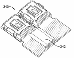
도 23은, 모듈간 전력 커넥터(340)를 사용하여 두 개의 배터리 모듈(101)이 함께 연결되어 있는 배터리 팩(100)의 다른 일부를 도시한다. 도 24는 모듈간 전력 커넥터(module-to-module power connector; 340)의 사시도이다.Fig. 23 shows another part of the
양과 음의 배터리 단자들(320, 300)은 정면 캐리어(230)를 따라 적절한 위치에서 대응하는 트레이(232)와 정면 트레이(244) 내에 로딩된다. 전력 커넥터(340)는 단자들(320, 300)에 정합된 모듈간 암 커넥터(340)의 형태로 된 것이다.Positive and
모듈간 암 커넥터(340)는, 브리지(342)에 의해 연결된, 암 커넥터들(310)과 유사한 두 개의 암 커넥터를 포함한다. 브리지(342)는 단자들(320, 300) 간의 상대적 이동을 허용하도록 유연한 브리지일 수 있다. 브리지(342)는 로우 프로파일을 갖는다. 브리지(342)는 암 단자들(310)을 제조하는 데 사용되는 프로그레션 다이(progression die)로부터의 캐리어로부터 형성될 수 있고, 여기서 프로그레션 다이로부터의 캐리어는 두 개의 암 커넥터(310) 사이에서 제거되지 않으며, 이에 따라, 브리지(342)를 규정하게 된다. 브리지(342)는 암 커넥터들(310) 간의 상대적 이동과 진동 에너지를 수용한다.The inter-module
도 25는 예시적인 일 실시예에 따라 형성된 서미스터(350)의 사시도이다. 도 26은 인접하는 배터리 셀들(102) 사이에 로딩된 서미스터(350)를 도시한다. 서미스터(350)는 베이스(354)로부터 연장되는 와이어들(352)을 포함한다. 베이스(354)는 캐리어(200 또는 300)의 대응하는 개구(356) 내에 수용된다. 서미스터(350)는 배터리 셀들(102) 중 임의의 두 개의 배터리 셀 사이에 위치할 수 있다. 캐리어들(200, 230)은 서미스터(350)를 위한 많은 위치를 허용함으로써 서미스터(350)의 유연한 위치 설정을 제공한다. 선택 사항으로, 배터리 모듈(101)의 서로 다른 위치에서의 온도를 감지하도록 서로 다른 배터리 셀들(102) 사이에 다수의 서미스터들(350)을 사용할 수도 있다. 개구(356)는 배터리 셀들(102) 간의 계면에서 서미스터를 적절히 정렬시킨다. 와이어들(352)은 전압 감지 와이어들이 경로 설정되어 있는 동일한 영역을 통해 캐리어(200 또는 300)로부터 멀어지도록 경로 설정될 수 있다.25 is a perspective view of a
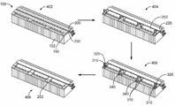
도 27은 배터리 팩(100)의 예시적인 조립 방법을 도시한다. 단계(400)에서는, 전압 감지 시스템과 온도 감지 시스템을 위한 대응하는 버스 바들(150)과 와이어 하니스들과 함께 캐리어들(200, 230)을 배터리 셀들(102)에 로딩한다. 버스 바들(150)은 예를 들어 레이저 용접에 의해 대응하는 셀 단자들(120, 122)에 기계적으로 그리고 전기적으로 연결된다.Fig. 27 shows an exemplary assembling method of the
단계(402)에서는, 커버들(220, 250)을 캐리어들(200, 230)에 각각 결합한다. 단계(404)에서는, 암 커넥터들(310)과 모듈간 암 커넥터들(340)을 대응하는 양과 음의 배터리 단자들(320, 300)에 결합한다. 전력 케이블들은 예를 들어 초음파 용접에 의해 암 커넥터들(310)에 종단된다. 단계(406)에서는, 리드들(252)을 폐쇄한다.In
위 설명은 예시적이며 제한적이지 않다는 점을 이해하기 바란다. 예를 들어, 전술한 실시예들(및/또는 그 양태들)은 서로 조합하여 사용될 수 있다. 또한, 본 발명의 범위로부터 벗어나지 않고서 특정한 상황이나 물질을 본 발명의 교시에 적응시키도록 많은 수정을 행할 수 있다. 본 명세서에서 설명하는 치수, 물질들의 유형, 다양한 구성요소들의 배향, 및 다양한 구성요소들의 개수와 위치는, 일부 실시예들의 파라미터들을 규정하려는 것이며, 결코 제한적이지 않으며 예시적인 실시예들일 뿐이다. 청구범위의 사상과 범위 내에서의 다른 많은 실시예들과 수정예들은, 위 설명을 읽는 통상의 기술자에겐 명백할 것이다.It is to be understood that the above description is intended to be illustrative and not restrictive. For example, the above-described embodiments (and / or aspects thereof) may be used in combination with one another. In addition, many modifications may be made to adapt a particular situation or material to the teachings of the invention without departing from its scope. The dimensions, the type of materials, the orientation of the various elements, and the number and location of the various elements described herein are intended to define the parameters of some embodiments, and are by no means limiting, and are exemplary embodiments only. Many other embodiments and modifications within the spirit and scope of the claims will be apparent to those of ordinary skill in the art upon reading the foregoing description.
Claims (10)
복수의 배터리 셀(102)로서, 각 배터리 셀이 양과 음의 셀 단자들(120, 122)을 갖는 것인, 상기 복수의 배터리 셀;
상기 복수의 배터리 셀 위에 장착되며, 상기 복수의 배터리 셀에 걸쳐 이어지는 캐리어(230)로서, 상기 양과 음의 셀 단자들을 노출시키는 개구들(236, 238)이 있는 트레이들(232)을 구비하는, 상기 캐리어; 및
대응하는 트레이들 내에 수용되는 복수의 버스 바(150)로서, 상기 복수의 버스 바의 각각은, 대응하는 개구를 통해 대응하는 배터리 셀의 양의 셀 단자에 레이저 용접된 양의 판(152) 및 대응하는 개구를 통해 다른 배터리 셀의 음의 셀 단자에 레이저 용접된 음의 판(154)을 구비하는 것인, 상기 복수의 버스 바를 포함하는, 배터리 팩(100).As the battery pack 100,
A plurality of battery cells (102), each battery cell having positive and negative cell terminals (120, 122);
And trays 232 mounted on the plurality of battery cells and having carriers 236 and 238 exposing the positive and negative cell terminals as a carrier 230 running across the plurality of battery cells. The carrier; And
A plurality of bus bars (150) received in corresponding trays, each of the plurality of bus bars comprising a positive plate (152) laser welded to a positive cell terminal of a corresponding battery cell through a corresponding opening, And a negative plate (154) laser-welded to negative cell terminals of other battery cells through corresponding openings.
상기 양과 음의 배터리 단자들의 각각은 빠른 연결 단부들(304)을 갖고, 상기 배터리 팩은, 상기 양과 음의 배터리 단자들을 전기적으로 연결하도록 상기 양과 음의 배터리 단자들의 빠른 연결 단부들에 연결된 모듈간 단자(module to module terminal; 340)를 더 포함하는, 배터리 팩(100).The battery pack of claim 1, further comprising a positive battery terminal (320) received in the carrier (230) and terminated in a corresponding positive cell terminal (120), and a negative battery terminal Further comprising a terminated negative battery terminal 322,
Each of the positive and negative battery terminals has fast connection ends 304 and the battery pack is connected between modules connected to the fast connection ends of the positive and negative battery terminals to electrically connect the positive and negative battery terminals Further comprising a module to module terminal (340).
Applications Claiming Priority (5)
| Application Number | Priority Date | Filing Date | Title |
|---|---|---|---|
| US201261649820P | 2012-05-21 | 2012-05-21 | |
| US61/649,820 | 2012-05-21 | ||
| US13/839,931 | 2013-03-15 | ||
| US13/839,931 US9105912B2 (en) | 2012-05-21 | 2013-03-15 | Boltless battery cell connection |
| PCT/US2013/040731 WO2013176913A1 (en) | 2012-05-21 | 2013-05-13 | Boltless battery cell connection |
Publications (1)
| Publication Number | Publication Date |
|---|---|
| KR20150003866A true KR20150003866A (en) | 2015-01-09 |
Family
ID=49581547
Family Applications (1)
| Application Number | Title | Priority Date | Filing Date |
|---|---|---|---|
| KR1020147032796A KR20150003866A (en) | 2012-05-21 | 2013-05-13 | Boltless battery cell connection |
Country Status (6)
| Country | Link |
|---|---|
| US (1) | US9105912B2 (en) |
| EP (1) | EP2852992B1 (en) |
| JP (1) | JP6497780B2 (en) |
| KR (1) | KR20150003866A (en) |
| CN (1) | CN104321905B (en) |
| WO (1) | WO2013176913A1 (en) |
Cited By (2)
| Publication number | Priority date | Publication date | Assignee | Title |
|---|---|---|---|---|
| KR20170142659A (en) * | 2016-06-20 | 2017-12-28 | 한국광기술원 | Busbar for bonding battery cell and method for battery cell using the same |
| US10559808B2 (en) | 2015-04-30 | 2020-02-11 | Lg Chem, Ltd. | Lithium secondary battery having improved safety by using bimetal tab |
Families Citing this family (23)
| Publication number | Priority date | Publication date | Assignee | Title |
|---|---|---|---|---|
| US9318734B2 (en) * | 2012-05-21 | 2016-04-19 | Tyco Electronics Corporation | Bimetal buss bar assembly |
| CN107672582A (en) * | 2012-06-13 | 2018-02-09 | 艾里逊变速箱公司 | Energy storage system with array resistant closure |
| US10056596B2 (en) * | 2013-06-06 | 2018-08-21 | Te Connectivity Corporation | Battery connector assembly |
| EP2874198B1 (en) * | 2013-11-15 | 2017-11-01 | Saft Groupe S.A. | Battery design with bussing integral to battery assembly |
| JPWO2015125936A1 (en) * | 2014-02-20 | 2017-03-30 | 矢崎総業株式会社 | Power supply |
| JP6315278B2 (en) | 2014-12-25 | 2018-04-25 | 株式会社オートネットワーク技術研究所 | Power storage module |
| US10062931B2 (en) * | 2015-04-22 | 2018-08-28 | Johnson Controls Technology Company | Welding process for battery module components |
| US9917291B2 (en) | 2015-05-05 | 2018-03-13 | Johnson Controls Technology Company | Welding process for a battery module |
| DE102016103841A1 (en) | 2016-03-03 | 2017-09-07 | Johnson Controls Advanced Power Solutions Gmbh | Attachment of electrochemical cells in a housing of a battery module |
| US10454080B2 (en) * | 2016-07-13 | 2019-10-22 | Te Connectivity Corporation | Connector assembly for a battery system |
| US11031728B2 (en) * | 2016-11-23 | 2021-06-08 | Black & Decker Inc. | Electrical connector |
| KR102617138B1 (en) | 2016-12-07 | 2023-12-26 | 삼성에스디아이 주식회사 | Battery pack |
| WO2018126437A1 (en) * | 2017-01-06 | 2018-07-12 | 宁德时代新能源科技股份有限公司 | Power battery top cover structure, power battery and battery module |
| DE102017200311A1 (en) * | 2017-01-10 | 2018-07-12 | Bayerische Motoren Werke Aktiengesellschaft | Battery, carrier board and carrier board element with locking elements |
| US11239526B2 (en) | 2017-03-15 | 2022-02-01 | Gs Yuasa International Ltd. | Energy storage apparatus |
| JP2019008877A (en) * | 2017-06-20 | 2019-01-17 | 矢崎総業株式会社 | Wire connection bus bar and conductive module |
| WO2020090492A1 (en) * | 2018-10-31 | 2020-05-07 | ビークルエナジージャパン株式会社 | Battery module |
| CN111384347B (en) * | 2018-12-29 | 2022-08-30 | 东莞莫仕连接器有限公司 | Battery connection module |
| WO2020154330A1 (en) | 2019-01-21 | 2020-07-30 | Royal Precision Products, Llc | Power distribution assembly with boltless busbar system |
| US20220149487A1 (en) * | 2019-03-12 | 2022-05-12 | Vehicle Energy Japan Inc. | Bus Bar, and Battery Module Using Same |
| CN114788112A (en) | 2019-09-09 | 2022-07-22 | 伊顿智能动力有限公司 | Electrical bus and method for manufacturing the same |
| EP3886207A1 (en) * | 2020-03-27 | 2021-09-29 | TE Connectivity Germany GmbH | Cell connecting system for a vehicle battery module and method for manufacturing the cell system |
| WO2023010510A1 (en) * | 2021-08-06 | 2023-02-09 | 江苏时代新能源科技有限公司 | Battery, electrical device, and battery manufacturing method and equipment |
Family Cites Families (19)
| Publication number | Priority date | Publication date | Assignee | Title |
|---|---|---|---|---|
| JPS58150269U (en) * | 1982-04-02 | 1983-10-08 | 三洋電機株式会社 | battery device |
| US5626984A (en) * | 1995-11-16 | 1997-05-06 | Albini; Salvatore | Battery terminal system |
| JP3707595B2 (en) * | 1998-09-09 | 2005-10-19 | 矢崎総業株式会社 | Battery connection plate |
| JP4637320B2 (en) * | 1999-05-14 | 2011-02-23 | 株式会社半導体エネルギー研究所 | Goggles type display device |
| DE10012387C2 (en) * | 2000-03-14 | 2002-10-02 | Itt Mfg Enterprises Inc | Arrangement for connecting a cable to a motor vehicle battery pole |
| JP2002151045A (en) * | 2000-11-10 | 2002-05-24 | Honda Motor Co Ltd | Bus bar for battery module and battery module |
| JP3860520B2 (en) * | 2002-09-04 | 2006-12-20 | 矢崎総業株式会社 | Mold structure for resin plate of battery connection plate |
| US7367847B2 (en) * | 2005-09-02 | 2008-05-06 | Alcoa Fujikura Ltd | Integrated module connection for HEV battery |
| EP2109906B1 (en) * | 2007-02-09 | 2016-09-07 | Johnson Controls Advanced Power Solutions LLC | Buss bar for batteries |
| JP5285997B2 (en) * | 2008-08-27 | 2013-09-11 | 矢崎総業株式会社 | Power supply |
| KR101082862B1 (en) * | 2008-10-14 | 2011-11-11 | 주식회사 엘지화학 | Battery Pack Containing Electrode Terminal Connecting Device |
| KR101087036B1 (en) * | 2008-12-17 | 2011-11-25 | 주식회사 엘지화학 | Electrode Terminal Connecting Device and Battery Module Assembly Employed with the Same |
| US20100248010A1 (en) * | 2009-01-12 | 2010-09-30 | A123 Systems, Inc. | Bi-metallic busbar jumpers for battery systems |
| WO2010085636A2 (en) | 2009-01-23 | 2010-07-29 | Johnson Controls - Saft Advanced Power Solutions Llc | Battery module having electrochemical cells with integrally formed terminals |
| JP5465440B2 (en) * | 2009-01-28 | 2014-04-09 | 三洋電機株式会社 | Assembled battery |
| JP5537111B2 (en) * | 2009-09-30 | 2014-07-02 | 株式会社東芝 | Secondary battery device |
| US8580423B2 (en) * | 2009-10-22 | 2013-11-12 | Samsung Sdi Co., Ltd. | Bus bar holder and battery pack including the same |
| CN102870254B (en) * | 2010-03-29 | 2014-12-31 | 株式会社神户制钢所 | Bus bar and method for producing bus bar |
| KR101201747B1 (en) * | 2010-05-24 | 2012-11-15 | 에스비리모티브 주식회사 | Battery module |
-
2013
- 2013-03-15 US US13/839,931 patent/US9105912B2/en active Active
- 2013-05-13 WO PCT/US2013/040731 patent/WO2013176913A1/en active Application Filing
- 2013-05-13 KR KR1020147032796A patent/KR20150003866A/en active Search and Examination
- 2013-05-13 EP EP13740392.9A patent/EP2852992B1/en active Active
- 2013-05-13 CN CN201380026698.8A patent/CN104321905B/en active Active
- 2013-05-13 JP JP2015514048A patent/JP6497780B2/en active Active
Cited By (2)
| Publication number | Priority date | Publication date | Assignee | Title |
|---|---|---|---|---|
| US10559808B2 (en) | 2015-04-30 | 2020-02-11 | Lg Chem, Ltd. | Lithium secondary battery having improved safety by using bimetal tab |
| KR20170142659A (en) * | 2016-06-20 | 2017-12-28 | 한국광기술원 | Busbar for bonding battery cell and method for battery cell using the same |
Also Published As
| Publication number | Publication date |
|---|---|
| JP2015520934A (en) | 2015-07-23 |
| EP2852992B1 (en) | 2018-09-05 |
| EP2852992A1 (en) | 2015-04-01 |
| US20130309537A1 (en) | 2013-11-21 |
| CN104321905B (en) | 2018-04-06 |
| CN104321905A (en) | 2015-01-28 |
| WO2013176913A1 (en) | 2013-11-28 |
| JP6497780B2 (en) | 2019-04-10 |
| US9105912B2 (en) | 2015-08-11 |
Similar Documents
| Publication | Publication Date | Title |
|---|---|---|
| EP2852992B1 (en) | Boltless battery cell connection | |
| JP6099211B2 (en) | Battery connector system | |
| KR102255240B1 (en) | Battery connector assembly | |
| CN110770946B (en) | Battery module, battery pack, and vehicle including the battery pack | |
| EP2421070B1 (en) | Battery pack | |
| KR101621182B1 (en) | Battery connector system | |
| KR102146936B1 (en) | Battery distribution unit | |
| EP3651237A1 (en) | Battery pack with improved assembly structure | |
| WO2016077266A1 (en) | Bus bar for a battery connector system | |
| KR20160086418A (en) | Bimetal buss bar assembly | |
| JP6793841B2 (en) | Battery module, battery pack including it and automobile | |
| JP2013093307A (en) | Wiring module for cell | |
| JP2013098032A (en) | Connection structure of voltage detection terminal | |
| JP2013152918A (en) | Wiring module | |
| JP6865724B2 (en) | How to assemble the busbar module | |
| EP4053989A1 (en) | Battery module having busbar, battery pack and vehicle | |
| JP2019520686A (en) | Connector assembly for battery system | |
| JP2016009645A (en) | Bus bar, chain bus bar, and wiring module | |
| CN112042004B (en) | Battery module comprising a module housing | |
| CN116235351A (en) | Battery wiring module | |
| CN113728519A (en) | FFC cable assembly | |
| EP4354644A1 (en) | Cell module assembly and battery pack comprising same | |
| JP2021136161A (en) | Busbar module and assembly method thereof | |
| CN114762177A (en) | Wire harness, power storage module, and method for manufacturing wire harness |
Legal Events
| Date | Code | Title | Description |
|---|---|---|---|
| A201 | Request for examination | ||
| E902 | Notification of reason for refusal | ||
| AMND | Amendment | ||
| E601 | Decision to refuse application | ||
| AMND | Amendment |