KR20140148316A - System and method for treating fluid mixtures including aqueous and organic phases - Google Patents
System and method for treating fluid mixtures including aqueous and organic phases Download PDFInfo
- Publication number
- KR20140148316A KR20140148316A KR1020140073434A KR20140073434A KR20140148316A KR 20140148316 A KR20140148316 A KR 20140148316A KR 1020140073434 A KR1020140073434 A KR 1020140073434A KR 20140073434 A KR20140073434 A KR 20140073434A KR 20140148316 A KR20140148316 A KR 20140148316A
- Authority
- KR
- South Korea
- Prior art keywords
- outlet
- flow path
- fluid
- filter element
- inlet
- Prior art date
Links
Images
Classifications
-
- B—PERFORMING OPERATIONS; TRANSPORTING
- B01—PHYSICAL OR CHEMICAL PROCESSES OR APPARATUS IN GENERAL
- B01D—SEPARATION
- B01D61/00—Processes of separation using semi-permeable membranes, e.g. dialysis, osmosis or ultrafiltration; Apparatus, accessories or auxiliary operations specially adapted therefor
- B01D61/58—Multistep processes
-
- B—PERFORMING OPERATIONS; TRANSPORTING
- B01—PHYSICAL OR CHEMICAL PROCESSES OR APPARATUS IN GENERAL
- B01D—SEPARATION
- B01D17/00—Separation of liquids, not provided for elsewhere, e.g. by thermal diffusion
- B01D17/08—Thickening liquid suspensions by filtration
- B01D17/085—Thickening liquid suspensions by filtration with membranes
-
- B—PERFORMING OPERATIONS; TRANSPORTING
- B01—PHYSICAL OR CHEMICAL PROCESSES OR APPARATUS IN GENERAL
- B01D—SEPARATION
- B01D17/00—Separation of liquids, not provided for elsewhere, e.g. by thermal diffusion
- B01D17/08—Thickening liquid suspensions by filtration
- B01D17/10—Thickening liquid suspensions by filtration with stationary filtering elements
-
- B—PERFORMING OPERATIONS; TRANSPORTING
- B01—PHYSICAL OR CHEMICAL PROCESSES OR APPARATUS IN GENERAL
- B01D—SEPARATION
- B01D61/00—Processes of separation using semi-permeable membranes, e.g. dialysis, osmosis or ultrafiltration; Apparatus, accessories or auxiliary operations specially adapted therefor
- B01D61/14—Ultrafiltration; Microfiltration
- B01D61/145—Ultrafiltration
- B01D61/146—Ultrafiltration comprising multiple ultrafiltration steps
-
- B—PERFORMING OPERATIONS; TRANSPORTING
- B01—PHYSICAL OR CHEMICAL PROCESSES OR APPARATUS IN GENERAL
- B01D—SEPARATION
- B01D61/00—Processes of separation using semi-permeable membranes, e.g. dialysis, osmosis or ultrafiltration; Apparatus, accessories or auxiliary operations specially adapted therefor
- B01D61/14—Ultrafiltration; Microfiltration
- B01D61/147—Microfiltration
- B01D61/1471—Microfiltration comprising multiple microfiltration steps
-
- B—PERFORMING OPERATIONS; TRANSPORTING
- B01—PHYSICAL OR CHEMICAL PROCESSES OR APPARATUS IN GENERAL
- B01D—SEPARATION
- B01D67/00—Processes specially adapted for manufacturing semi-permeable membranes for separation processes or apparatus
- B01D67/0081—After-treatment of organic or inorganic membranes
- B01D67/0088—Physical treatment with compounds, e.g. swelling, coating or impregnation
-
- B—PERFORMING OPERATIONS; TRANSPORTING
- B01—PHYSICAL OR CHEMICAL PROCESSES OR APPARATUS IN GENERAL
- B01D—SEPARATION
- B01D69/00—Semi-permeable membranes for separation processes or apparatus characterised by their form, structure or properties; Manufacturing processes specially adapted therefor
- B01D69/02—Semi-permeable membranes for separation processes or apparatus characterised by their form, structure or properties; Manufacturing processes specially adapted therefor characterised by their properties
-
- C—CHEMISTRY; METALLURGY
- C02—TREATMENT OF WATER, WASTE WATER, SEWAGE, OR SLUDGE
- C02F—TREATMENT OF WATER, WASTE WATER, SEWAGE, OR SLUDGE
- C02F1/00—Treatment of water, waste water, or sewage
- C02F1/44—Treatment of water, waste water, or sewage by dialysis, osmosis or reverse osmosis
- C02F1/444—Treatment of water, waste water, or sewage by dialysis, osmosis or reverse osmosis by ultrafiltration or microfiltration
-
- C—CHEMISTRY; METALLURGY
- C10—PETROLEUM, GAS OR COKE INDUSTRIES; TECHNICAL GASES CONTAINING CARBON MONOXIDE; FUELS; LUBRICANTS; PEAT
- C10G—CRACKING HYDROCARBON OILS; PRODUCTION OF LIQUID HYDROCARBON MIXTURES, e.g. BY DESTRUCTIVE HYDROGENATION, OLIGOMERISATION, POLYMERISATION; RECOVERY OF HYDROCARBON OILS FROM OIL-SHALE, OIL-SAND, OR GASES; REFINING MIXTURES MAINLY CONSISTING OF HYDROCARBONS; REFORMING OF NAPHTHA; MINERAL WAXES
- C10G33/00—Dewatering or demulsification of hydrocarbon oils
- C10G33/06—Dewatering or demulsification of hydrocarbon oils with mechanical means, e.g. by filtration
-
- B—PERFORMING OPERATIONS; TRANSPORTING
- B01—PHYSICAL OR CHEMICAL PROCESSES OR APPARATUS IN GENERAL
- B01D—SEPARATION
- B01D2315/00—Details relating to the membrane module operation
- B01D2315/10—Cross-flow filtration
-
- B—PERFORMING OPERATIONS; TRANSPORTING
- B01—PHYSICAL OR CHEMICAL PROCESSES OR APPARATUS IN GENERAL
- B01D—SEPARATION
- B01D2315/00—Details relating to the membrane module operation
- B01D2315/12—Feed-and-bleed systems
-
- B—PERFORMING OPERATIONS; TRANSPORTING
- B01—PHYSICAL OR CHEMICAL PROCESSES OR APPARATUS IN GENERAL
- B01D—SEPARATION
- B01D2315/00—Details relating to the membrane module operation
- B01D2315/14—Batch-systems
-
- B—PERFORMING OPERATIONS; TRANSPORTING
- B01—PHYSICAL OR CHEMICAL PROCESSES OR APPARATUS IN GENERAL
- B01D—SEPARATION
- B01D2317/00—Membrane module arrangements within a plant or an apparatus
- B01D2317/08—Use of membrane modules of different kinds
-
- B—PERFORMING OPERATIONS; TRANSPORTING
- B01—PHYSICAL OR CHEMICAL PROCESSES OR APPARATUS IN GENERAL
- B01D—SEPARATION
- B01D2325/00—Details relating to properties of membranes
- B01D2325/36—Hydrophilic membranes
-
- B—PERFORMING OPERATIONS; TRANSPORTING
- B01—PHYSICAL OR CHEMICAL PROCESSES OR APPARATUS IN GENERAL
- B01D—SEPARATION
- B01D2325/00—Details relating to properties of membranes
- B01D2325/38—Hydrophobic membranes
-
- C—CHEMISTRY; METALLURGY
- C02—TREATMENT OF WATER, WASTE WATER, SEWAGE, OR SLUDGE
- C02F—TREATMENT OF WATER, WASTE WATER, SEWAGE, OR SLUDGE
- C02F2101/00—Nature of the contaminant
- C02F2101/30—Organic compounds
- C02F2101/32—Hydrocarbons, e.g. oil
-
- C—CHEMISTRY; METALLURGY
- C02—TREATMENT OF WATER, WASTE WATER, SEWAGE, OR SLUDGE
- C02F—TREATMENT OF WATER, WASTE WATER, SEWAGE, OR SLUDGE
- C02F2301/00—General aspects of water treatment
- C02F2301/02—Fluid flow conditions
- C02F2301/026—Spiral, helicoidal, radial
-
- C—CHEMISTRY; METALLURGY
- C02—TREATMENT OF WATER, WASTE WATER, SEWAGE, OR SLUDGE
- C02F—TREATMENT OF WATER, WASTE WATER, SEWAGE, OR SLUDGE
- C02F2301/00—General aspects of water treatment
- C02F2301/08—Multistage treatments, e.g. repetition of the same process step under different conditions
Landscapes
- Chemical & Material Sciences (AREA)
- Engineering & Computer Science (AREA)
- Chemical Kinetics & Catalysis (AREA)
- Water Supply & Treatment (AREA)
- Oil, Petroleum & Natural Gas (AREA)
- Thermal Sciences (AREA)
- Organic Chemistry (AREA)
- Physics & Mathematics (AREA)
- Life Sciences & Earth Sciences (AREA)
- Hydrology & Water Resources (AREA)
- Environmental & Geological Engineering (AREA)
- Mechanical Engineering (AREA)
- General Chemical & Material Sciences (AREA)
- Inorganic Chemistry (AREA)
- Manufacturing & Machinery (AREA)
- Separation Using Semi-Permeable Membranes (AREA)
- Extraction Or Liquid Replacement (AREA)
Abstract
Description
본 발명은 수상 및 유기상을 포함하는 유체 혼합물의 처리 시스템 및 처리 방법에 관한 것이다. The present invention relates to a treatment system and method of treating a fluid mixture comprising a water phase and an organic phase.
물과 오일은 물, 오일 및 고체를 포함하는 혼합물로부터 제거될 수 있다. 예를 들어, 대체 연료 시장에서, 일부 회사들은 3상 세퍼레이터(three phase separator)를 사용하여 유상(oil phase)으로부터 또한 고상(solids phase)으로부터 수상(water phase)을 분리한다. 다른 분리 방법은, 예를 들어, 하나 이상의 원심분리기의 사용을 포함한다.Water and oil may be removed from the mixture comprising water, oil and solids. For example, in the alternative fuel market, some companies use a three phase separator to separate the water phase from the oil phase and also from the solids phase. Other separation methods include, for example, the use of one or more centrifuges.
그러나, 종래의 분리 방법은 비효율성 및/또는 많은 비용을 발생시키고 있다.However, conventional separation methods are inefficient and / or costly.
본 발명은 종래 기술의 단점들의 적어도 일부에 대한 개선을 제공한다. 본 발명의 이들 및 다른 이점들은 하기의 상세한 설명으로부터 명백해질 것이다.The present invention provides an improvement over at least some of the disadvantages of the prior art. These and other advantages of the present invention will become apparent from the following detailed description.
본 발명의 일 구현예에 따라, 수상 및 유기상을 포함하는 유체를 처리하는 시스템이 제공되며, 상기 시스템은 제1 필터 장치 및 제2 필터 장치를 포함하고, 상기 제1 필터 장치는 하우징 및 친수성 필터 요소를 포함하고, 상기 하우징은 유입구, 제1 유출구 및 제2 유출구를 포함하고, 상기 하우징은 상기 유입구와 상기 제1 유출구 사이의 제1 유체 흐름 경로 및 상기 유입구와 상기 제2 유출구 사이의 제2 유체 흐름 경로를 한정하고, 상기 친수성 필터 요소는 상기 제1 유체 흐름 경로를 가로지르는 다공성 친수성 막을 포함하며, 상기 제2 필터 장치는 하우징 및 소수성 필터 요소를 포함하고, 상기 하우징은 유입구, 제1 유출구 및 제2 유출구를 포함하고, 상기 하우징은 상기 유입구와 상기 제1 유출구 사이의 제1 유체 흐름 경로 및 상기 유입구와 상기 제2 유출구 사이의 제2 유체 흐름 경로를 한정하고, 상기 소수성 필터 요소는 상기 제1 유체 흐름 경로를 가로지른다. 상기 필터 장치들은 직렬 또는 병렬로 배열될 수 있다. 바람직한 일 구현예에 있어서, 상기 제1 필터 장치의 상기 제2 유출구는 상기 제2 필터 장치의 상기 유입구와 유체 연통한다. According to an embodiment of the present invention there is provided a system for treating a fluid comprising an aqueous phase and an organic phase, the system comprising a first filter device and a second filter device, the first filter device comprising a housing and a hydrophilic filter Wherein the housing includes a first fluid flow path between the inlet and the first outlet, and a second fluid flow path between the inlet and the second outlet, wherein the housing comprises an inlet, a first outlet and a second outlet, The hydrophilic filter element comprising a porous hydrophilic membrane across the first fluid flow path, the second filter device comprising a housing and a hydrophobic filter element, the housing comprising an inlet, a first outlet And a second outlet, wherein the housing has a first fluid flow path between the inlet and the first outlet, and a second fluid flow path between the inlet and the second oil outlet, Defining a second fluid flow path between the sphere, and the hydrophobic filter element is across the first fluid flow path. The filter devices may be arranged in series or in parallel. In a preferred embodiment, the second outlet of the first filter device is in fluid communication with the inlet of the second filter device.
일부 구현예들에 있어서, 상기 소수성 필터 요소는 다공성 소수성 막을 포함한다. 바람직한 일 구현예에 있어서, 상기 소수성 필터 요소는 입자 코팅된 다공성 친수성 막 또는 입자 코팅된 다공성 소수성 막을 포함하고, 상기 입자는 약 25 dynes/cm(약 2.5 x 10⁻² N/m) 이하의 임계 젖음 표면 장력(Critical Wetting Surface Tension: CWST), 통상적으로, 약 22 dynes/cm 내지 약 16 dynes/cm (약 2.2 x 10⁻² N/m 내지 약 1.6 x 10⁻² N/m) 범위의 CWST를 갖고, 상기 코팅은 상기 막의 상류쪽 표면에 존재한다. 바람직하게는, 상기 코팅 중의 입자는 PTFE 입자를 포함한다. 통상적으로, 상기 코팅 아래의 상기 다공성 막은 약 23 dynes/cm 내지 약 78 dynes/cm (약 2.3 x 10⁻² N/m 내지 약 7.8 x 10⁻² N/m) 범위의 CWST를 갖는다.In some embodiments, the hydrophobic filter element comprises a porous hydrophobic membrane. In a preferred embodiment, the hydrophobic filter element comprises a particle-coated porous hydrophilic membrane or a particle-coated porous hydrophobic membrane, wherein the particles have a criticality of less than about 25 dynes / cm (about 2.5 x 10⁻² N / m) wetting surface tension (Critical wetting surface tension: CWST), typically, about 22 dynes / cm to about 16 dynes / cm (about 2.2 x 10 -2 N / m to about 1.6 x 10 -2 N / m) range of CWST And the coating is present on the upstream surface of the membrane. Preferably, the particles in the coating comprise PTFE particles. Typically, the film has from about 23 dynes / cm to about 78 dynes / cm (about 2.3 x 10 -2 N / m to about 7.8 x 10 -2 N / m) range of CWST of the porous under the coating.
다른 구현예에 있어서, 연속적 수상 및 불연속적 유기상을 포함하는 유체 혼합물(또한, 상기 혼합물은 바람직하게는 고상(solid phase)도 포함할 수 있음)을 처리하는 방법이 제공된다.In another embodiment, a method is provided for treating a fluid mixture comprising a continuous aqueous phase and a discontinuous organic phase (which may also include a solid phase, preferably the solid phase).
바람직한 일 구현예에 있어서, 상기 방법은 다음의 단계들을 포함한다: 상기 연속적 수상 및 불연속적 유기상의 혼합물을 제1 필터 장치의 유입구로 전달하는 단계로서, 상기 제1 필터 장치는 하우징 및 친수성 필터 요소를 포함하고, 상기 하우징은 상기 유입구, 제1 유출구 및 제2 유출구를 포함하고, 상기 하우징은 상기 유입구와 상기 제1 유출구 사이의 제1 유체 흐름 경로 및 상기 유입구와 상기 제2 유출구 사이의 제2 유체 흐름 경로를 한정하고, 상기 친수성 필터 요소는 상류쪽 표면 및 하류쪽 표면을 갖고, 상기 친수성 필터 요소는 상기 제1 유체 흐름 경로를 가로질러 배치되어 있는 단계; 상기 혼합물을 상기 상류쪽 표면에 대해 접선 방향으로 이송하는 단계; 상기 연속적 수상을 상기 제1 유체 흐름 경로를 따라 이송하고, 상기 친수성 필터 요소를 통하여 통과시키고, 상기 제1 유출구를 통하여 통과시키는 단계; 수상이 감소된 불연속적 유기상 함유 유체를 상기 상류쪽 표면에 대해 접선 방향으로 이송하고, 상기 제2 유체 흐름 경로를 따라 이송하고, 상기 제2 유출구를 통하여 통과시키고, 제2 필터 장치의 유입구를 통하여 통과시키는 단계로서, 상기 제2 필터 장치는 하우징 및 소수성 필터 요소를 포함하고, 상기 하우징은 상기 유입구, 제1 유출구 및 제2 유출구를 포함하고, 상기 하우징은 상기 유입구와 상기 제1 유출구 사이의 제1 유체 흐름 경로 및 상기 유입구와 상기 제2 유출구 사이의 제2 유체 흐름 경로를 한정하고, 상기 소수성 필터 요소는 상류쪽 표면 및 하류쪽 표면을 가지며, 상기 소수성 필터 요소는 상기 제1 유체 흐름 경로를 가로질러 배치되어 있는 단계; 상기 수상이 감소된 불연속적 유기상 함유 유체를 상기 상류쪽 표면에 대해 접선 방향으로 이송하는 단계; 상기 불연속적 유기상을 상기 제1 유체 흐름 경로를 따라 이송하고, 상기 소수성 필터 요소를 통하여 통과시키고, 상기 제1 유출구를 통하여 통과시키는 단계; 및 수상이 감소되고 불연속적 유기상이 감소된 유체를 상기 상류쪽 표면에 대해 접선 방향으로 이송하고, 상기 제2 유체 흐름 경로를 따라 이송하고, 상기 제2 유출구를 통하여 통과시키는 단계.In a preferred embodiment, the method comprises the steps of: conveying a mixture of continuous aqueous and discontinuous organic phases to an inlet of a first filter device, said first filter device comprising a housing and a hydrophilic filter element Wherein the housing includes a first fluid flow path between the inlet and the first outlet, and a second fluid flow path between the inlet and the second outlet, wherein the housing includes the inlet, the first outlet and the second outlet, The hydrophilic filter element defining a fluid flow path, the hydrophilic filter element having an upstream surface and a downstream surface, the hydrophilic filter element being disposed across the first fluid flow path; Transferring the mixture in a tangential direction relative to the upstream surface; Passing said continuous water phase along said first fluid flow path, through said hydrophilic filter element and through said first outlet; The fluid containing a water-reduced, discontinuous organic phase is transferred in a tangential direction relative to the upstream surface, transferred along the second fluid flow path, passed through the second outlet and passed through an inlet of the second filter device Wherein the second filter device comprises a housing and a hydrophobic filter element, the housing comprising the inlet, a first outlet and a second outlet, the housing having a first inlet and a second outlet, 1 fluid flow path and a second fluid flow path between the inlet and the second outlet, the hydrophobic filter element having an upstream surface and a downstream surface, the hydrophobic filter element defining a first fluid flow path A step disposed across; Transferring the water-reduced discontinuous organic phase containing fluid in a tangential direction relative to the upstream surface; Passing said discontinuous organic phase along said first fluid flow path, through said hydrophobic filter element and through said first outlet; And transferring a fluid having a reduced water phase and reduced discontinuous organic phase tangential to the upstream surface and transferring along the second fluid flow path and passing through the second outlet.
바람직하게는, 적어도 상기 소수성 필터 요소를 통과한 불연속적 유기상은 추가적인 가공, 재활용 또는 폐기를 위해 적합한 조건에서 회수된다. Preferably, the discontinuous organic phase which has passed at least the hydrophobic filter element is recovered under suitable conditions for further processing, recycling or disposal.
다른 구현예에 있어서, 상기 유체 혼합물은 연속적 수상, 불연속적 유기상 및 고상을 포함하고, 상기 방법은 다음의 단계들을 포함한다: 상기 혼합물을 상기 제1 필터 장치의 유입구로 전달하고, 상기 혼합물을 상기 상류쪽 표면에 대해 접선 방향으로 이송하는 단계; 상기 연속적 수상을 상기 제1 유체 흐름 경로를 따라 이송하고, 상기 친수성 필터 요소를 통하여 통과시키고, 상기 제1 유출구를 통하여 통과시키는 단계; 수상이 감소된 불연속적 유기상 및 고상 함유 유체를 상기 상류쪽 표면에 대해 접선 방향으로 이송하고, 상기 제2 유체 흐름 경로를 따라 이송하고, 상기 제2 유출구를 통하여 통과시키고, 상기 제2 필터 장치의 유입구를 통하여 통과시키는 단계; 상기 수상이 감소된 불연속적 유기상 및 고상 함유 유체를 상기 상류쪽 표면에 대해 접선 방향으로 이송하는 단계; 상기 불연속적 유기상을 상기 제1 유체 흐름 경로를 따라 이송하고, 상기 소수성 필터 요소를 통하여 통과시키고, 상기 제1 유출구를 통하여 통과시키는 단계; 및 수상이 감소되고 불연속적 유기상이 감소된 고상 함유 유체를 상기 상류쪽 표면에 대해 접선 방향으로 이송하고, 상기 제2 유체 흐름 경로를 따라 이송하고, 상기 제2 유출구를 통하여 통과시키는 단계.In another embodiment, the fluid mixture comprises a continuous aqueous phase, a discontinuous organic phase and a solid phase, the method comprising the steps of: transferring the mixture to an inlet of the first filter device, Transporting in a tangential direction with respect to an upstream surface; Passing said continuous water phase along said first fluid flow path, through said hydrophilic filter element and through said first outlet; Wherein the water-reduced discontinuous organic phase and the solid phase containing fluid are transferred tangentially to the upstream surface, transferred along the second fluid flow path, passed through the second outlet, Passing through an inlet; Transferring the water-reduced discontinuous organic phase and the solid phase containing fluid in a tangential direction relative to the upstream surface; Passing said discontinuous organic phase along said first fluid flow path, through said hydrophobic filter element and through said first outlet; And delivering the solid phase containing fluid with reduced water phase and reduced discontinuous organic phase tangential to the upstream surface and transporting along the second fluid flow path and passing through the second outlet.
일부 구현예들에 있어서, 상기 제2 필터 장치의 제2 유출구를 통과한 상기 수상이 감소되고 불연속적 유기상이 감소된 유체는, 새로운 또는 추가의 유체 혼합물이 상기 제1 필터 장치의 유입구를 통과하기 전에, 상기 새로운 또는 추가의 유체 혼합물과 혼합된다. 대안적으로, 또는 추가적으로, 상기 방법은 정용여과(diafiltration)를 포함할 수 있고, 정용여과 유체는, 새로운 또는 추가의 유체 혼합물이 상기 제1 필터 장치의 유입구를 통과하기 전에, 상기 새로운 또는 추가의 유체 혼합물과 혼합된다. In some embodiments, the fluid that has passed through the second outlet of the second filtration device and has reduced water phase and reduced discontinuous organic phase may cause a new or additional fluid mixture to pass through the inlet of the first filter device Before it is mixed with the new or additional fluid mixture. Alternatively, or in addition, the method may comprise diafiltration, wherein the diesel filtration fluid is introduced into the first filter device before the new or additional fluid mixture passes through the inlet of the first filter device, Fluid mixture.
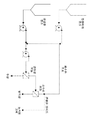
도 1은 본 발명의 일 구현예에 따라 사용되기 위한 시스템을 도시하는 다이아그램인데, 이때 필터 장치들은 직렬로 배열되어 있고, 또한 이 시스템은 선택적인(optional) 정용여과 탱크 및 유로, 및 선택적인(optional) 잔류물 블리드(retentate bleed)를 포함하고 있다.
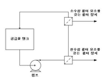
도 2는 본 발명의 일 구현예에 따라 사용되기 위한 시스템을 도시하는 다이아그램인데, 필터 장치들이 직렬로 배열되어 있는데, 2 개의 필터 장치 중 어느 하나든지 먼저 배열될 수 있다.
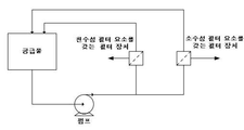
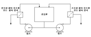
도 3a 및 3b는 본 발명의 구현예들에 따른 사용을 위한 또 다른 시스템들을 도시하는데, 도 3a는 단일 펌프 병렬 루프(single pump parallel loop)를 도시하고, 도 3b는 이중(dual) 펌프 병렬 루프를 도시한다.
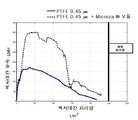
도 4는 제2 필터 장치만을 사용한 경우와 비교된, 본 발명의 일 구현예에 따른 제1 및 제2 필터 장치를 포함하는 시스템을 사용한 처리량(throughput)을 보여주는 그래프이다.
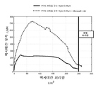
도 5는 제2 필터 장치만을 사용한 경우와 비교된, 본 발명의 다른 구현예에 따른 제1 및 제2 필터 장치를 포함하는 시스템을 사용한 처리량을 보여주는 그래프이다. Figure 1 is a diagram illustrating a system for use in accordance with an embodiment of the present invention wherein the filter devices are arranged in series and the system also includes an optional dental filtration tank and a flow path, and an optional retentate bleed.
Figure 2 is a diagram illustrating a system for use in accordance with an embodiment of the present invention in which the filter devices are arranged in series and any one of the two filter devices can be arranged first.
Figures 3a and 3b show further systems for use in accordance with embodiments of the present invention, wherein Figure 3a shows a single pump parallel loop, Figure 3b shows a dual pump parallel loop / RTI >
4 is a graph showing throughput using a system including first and second filter devices in accordance with an embodiment of the present invention, compared to using only a second filter device.
5 is a graph showing the throughput using a system including first and second filter devices according to another embodiment of the present invention compared to the case of using only the second filter device.
유리하게도, 본 발명에 따른 시스템 및 방법은, 높은 표면 에너지의 연속적 액상(liquid phase) (바람직하게는, 물과 같은 수상) 및 낮은 표면 에너지의 불연속적 액상(바람직하게는 유기상, 더욱 바람직하게는 오일)을, 초기에 이 두 상을 함유하는 혼합물로부터 분리하는 데에 사용될 수 있다.Advantageously, the system and method according to the present invention are characterized in that a continuous liquid phase of high surface energy (preferably a water phase such as water) and a discontinuous liquid phase of low surface energy (preferably an organic phase, Oil) can be initially used to separate from the mixture containing these two phases.
추가적으로, 수상을 분리함으로써 유기상 농도를 유지할 수 있게 되는데, 이를 통하여, 바람직한 높은 수준의 유기상 농도를 유지할 수 있고, 또한, 오일 유속(oil flux)이 더 긴 시간 동안 높은 수준으로 유지되는 것을 가능하게 한다. In addition, by separating the water phase, the organic phase concentration can be maintained, through which a desired high level of organic phase concentration can be maintained and also the oil flux can be maintained at a high level for a longer period of time .
본 발명의 일 구현예에 따라, 수상 및 유기상을 포함하는 유체를 처리하는 시스템이 제공되는 데, 이 시스템은 제1 필터 장치 및 제2 필터 장치를 포함하고, 제1 필터 장치는 하우징 및 친수성 필터 요소를 포함하고, 하우징은 유입구, 제1 유출구 및 제2 유출구를 포함하고, 하우징은 유입구와 제1 유출구 사이의 제1 유체 흐름 경로 및 유입구와 제2 유출구 사이의 제2 유체 흐름 경로를 한정하고, 친수성 필터 요소는 제1 유체 흐름 경로를 가로지르는 다공성 친수성 막을 포함하며, 제2 필터 장치는 하우징 및 소수성 필터 요소를 포함하고, 하우징은 유입구, 제1 유출구 및 제2 유출구를 포함하고, 하우징은 유입구와 제1 유출구 사이의 제1 유체 흐름 경로 및 유입구와 제2 유출구 사이의 제2 유체 흐름 경로를 한정하고, 소수성 필터 요소는 제1 유체 흐름 경로를 가로지른다. 상기 필터 장치들은 직렬(소수성 필터 요소를 포함하는 필터 장치의 상류쪽에 친수성 필터 요소를 포함하는 필터 장치가 배열되거나, 또는 친수성 필터 요소를 포함하는 필터 장치의 상류쪽에 소수성 필터 요소를 포함하는 필터 장치가 배열됨), 또는 병렬로 배열될 수 있다. 바람직한 일 구현예에 있어서, 제1 필터 장치의 제2 유출구는 제2 필터 장치의 유입구와 유체 연통한다. According to an embodiment of the present invention, there is provided a system for treating a fluid comprising a water phase and an organic phase, the system comprising a first filter device and a second filter device, the first filter device comprising a housing and a hydrophilic filter Wherein the housing defines an inlet, a first outlet and a second outlet, the housing defining a first fluid flow path between the inlet and the first outlet and a second fluid flow path between the inlet and the second outlet, , The hydrophilic filter element comprises a porous hydrophilic membrane across the first fluid flow path, the second filter device comprising a housing and a hydrophobic filter element, the housing comprising an inlet, a first outlet and a second outlet, A first fluid flow path between the inlet and the first outlet and a second fluid flow path between the inlet and the second outlet, the hydrophobic filter element defining a first fluid flow path between the inlet and the first outlet, Horizontal crosses. The filter devices may comprise a filter device comprising a hydrophilic filter element on the upstream side of a filter device comprising a hydrophobic filter element, or a filter device comprising a hydrophobic filter element on the upstream side of the filter device comprising a hydrophilic filter element Aligned), or arranged in parallel. In a preferred embodiment, the second outlet of the first filter device is in fluid communication with the inlet of the second filter device.
일부 구현예들에 있어서, 소수성 필터 요소는 다공성 소수성 막을 포함한다. 다른 구현예들에 있어서, 소수성 필터 요소는 입자 코팅된 다공성 친수성 막 또는 입자 코팅된 다공성 소수성 막을 포함하되, 입자는 약 25 dynes/cm(약 2.5 x 10⁻² N/m) 이하의 임계 젖음 표면 장력(Critical Wetting Surface Tension: CWST), 통상적으로, 약 22 dynes/cm 내지 약 16 dynes/cm (약 2.2 x 10⁻² N/m 내지 약 1.6 x 10⁻² N/m) 범위의 CWST를 갖는다. 바람직하게는, 상기 코팅 중의 입자는 PTFE 입자를 포함한다. 통상적으로, 상기 코팅 아래의 상기 다공성 막은 약 23 dynes/cm 내지 약 78 dynes/cm (약 2.3 x 10⁻² N/m 내지 약 7.8 x 10⁻² N/m) 범위의 CWST를 갖는다.In some embodiments, the hydrophobic filter element comprises a porous hydrophobic membrane. In other embodiments, the hydrophobic filter element comprises a particle-coated porous hydrophilic membrane or a particle-coated porous hydrophobic membrane, wherein the particles have a critical wetting surface of less than about 25 dynes / cm (about 2.5 x 10⁻² N / m) tension (Critical Wetting Surface tension: CWST), typically, from about 22 dynes / cm to about 16 dynes / cm (about 2.2 x 10 -2 N / m to about 1.6 x 10 -2 N / m) range of CWST . Preferably, the particles in the coating comprise PTFE particles. Typically, the film has from about 23 dynes / cm to about 78 dynes / cm (about 2.3 x 10 -2 N / m to about 7.8 x 10 -2 N / m) range of CWST of the porous under the coating.
다른 구현예에 있어서, 연속적 수상 및 불연속적 유기상을 포함하는 유체 혼합물(또한, 혼합물은 바람직하게는 고상을 포함함)을 처리하는 방법이 제공된다.In another embodiment, a method is provided for treating a fluid mixture comprising a continuous aqueous phase and a discontinuous organic phase (also, the mixture preferably comprises a solid phase).
바람직한 일 구현예에 있어서, 유체 혼합물 처리 방법은 다음의 단계들을 포함한다: 연속적 수상 및 불연속적 유기상의 혼합물을 제1 필터 장치의 유입구로 전달하는 단계로서, 제1 필터 장치는 하우징 및 친수성 필터 요소를 포함하고, 하우징은 유입구, 제1 유출구 및 제2 유출구를 포함하고, 하우징은 유입구와 제1 유출구 사이의 제1 유체 흐름 경로 및 유입구와 제2 유출구 사이의 제2 유체 흐름 경로를 한정하고, 친수성 필터 요소는 상류쪽 표면 및 하류쪽 표면을 갖고, 친수성 필터 요소는 상기 제1 유체 흐름 경로를 가로질러 배치되어 있는 단계; 혼합물을 상류쪽 표면에 대해 접선 방향으로 이송하는 단계; 연속적 수상을 제1 유체 흐름 경로를 따라 이송하고, 친수성 필터 요소를 통하여 통과시키고, 제1 유출구를 통하여 통과시키는 단계; 수상이 감소된 불연속적 유기상 함유 유체를 상류쪽 표면에 대해 접선 방향으로 이송하고, 제2 유체 흐름 경로를 따라 이송하고, 제2 유출구를 통하여 통과시키고, 제2 필터 장치의 유입구를 통하여 통과시키는 단계로서, 제2 필터 장치는 하우징 및 소수성 필터 요소를 포함하고, 하우징은 유입구, 제1 유출구 및 제2 유출구를 포함하고, 하우징은 유입구와 제1 유출구 사이의 제1 유체 흐름 경로 및 유입구와 제2 유출구 사이의 제2 유체 흐름 경로를 한정하고, 소수성 필터 요소는 상류쪽 표면 및 하류쪽 표면을 가지며, 소수성 필터 요소는 제1 유체 흐름 경로를 가로질러 배치되어 있는 단계; 수상이 감소된 불연속적 유기상 함유 유체를 상류쪽 표면에 대해 접선 방향으로 이송하는 단계; 불연속적 유기상을 제1 유체 흐름 경로를 따라 이송하고, 소수성 필터 요소를 통하여 통과시키고, 제1 유출구를 통하여 통과시키는 단계; 및 수상이 감소되고 불연속적 유기상이 감소된 유체를 상류쪽 표면에 대해 접선 방향으로 이송하고, 제2 유체 흐름 경로를 따라 이송하고, 제2 유출구를 통하여 통과시키는 단계.In a preferred embodiment, the method of treating a fluid mixture comprises the following steps: delivering a mixture of continuous aqueous and discontinuous organic phases to an inlet of a first filter device, wherein the first filter device comprises a housing and a hydrophilic filter element Wherein the housing defines an inlet, a first outlet and a second outlet, the housing defining a first fluid flow path between the inlet and the first outlet and a second fluid flow path between the inlet and the second outlet, Wherein the hydrophilic filter element has an upstream surface and a downstream surface, and wherein the hydrophilic filter element is disposed across the first fluid flow path; Transferring the mixture in a tangential direction relative to the upstream surface; Passing the continuous water phase along a first fluid flow path, passing through a hydrophilic filter element and passing through a first outlet; Passing the tapered discontinuous organic phase containing fluid in a tangential direction relative to the upstream surface, transporting along a second fluid flow path, passing through a second outlet, and passing through an inlet of a second filter device Wherein the housing includes a first fluid flow path and an inlet between the inlet and the first outlet, and a second fluid flow path between the inlet and the second outlet, wherein the housing comprises a housing and a hydrophobic filter element, the housing comprising an inlet, a first outlet and a second outlet, Wherein the hydrophobic filter element defines a second fluid flow path between the outlet and the hydrophobic filter element has an upstream surface and a downstream surface and wherein the hydrophobic filter element is disposed across the first fluid flow path; Transporting the water-reduced discontinuous organic phase containing fluid in a tangential direction relative to the upstream surface; Passing the discontinuous organic phase along a first fluid flow path, passing through a hydrophobic filter element, and passing through a first outlet; And transferring the fluid with reduced water phase and reduced discontinuous organic phase in a tangential direction relative to the upstream surface and transferring along the second fluid flow path and passing through the second outlet.
바람직하게는, 적어도 소수성 필터 요소를 통과한 불연속적 유기상은 추가적인 처리, 재활용 또는 처분을 위해 적합한 조건에서 회수된다. Preferably, the discontinuous organic phase which has passed through at least the hydrophobic filter element is recovered under suitable conditions for further processing, recycling or disposal.
다른 구현예에 있어서, 유체 혼합물은 연속적 수상, 불연속적 유기상 및 고상을 포함하고, 유체 혼합물 처리 방법은 다음의 단계들을 포함한다: 혼합물을 제1 필터 장치의 유입구로 전달하고, 혼합물을 상류쪽 표면에 대해 접선 방향으로 이송하는 단계; 연속적 수상을 제1 유체 흐름 경로를 따라 이송하고, 친수성 필터 요소를 통하여 통과시키고, 제1 유출구를 통하여 통과시키는 단계; 수상이 감소된 불연속적 유기상 및 고상 함유 유체를 상류쪽 표면에 대해 접선 방향으로 이송하고, 제2 유체 흐름 경로를 따라 이송하고, 제2 유출구를 통하여 통과시키고, 제2 필터 장치의 유입구를 통하여 통과시키는 단계; 수상이 감소된 불연속적 유기상 및 고상 함유 유체를 상류쪽 표면에 대해 접선 방향으로 이송하는 단계; 불연속적 유기상을 제1 유체 흐름 경로를 따라 이송하고, 소수성 필터 요소를 통하여 통과시키고, 제1 유출구를 통하여 통과시키는 단계; 및 수상이 감소되고 불연속적 유기상이 감소된 고상 함유 유체를 상류쪽 표면에 대해 접선 방향으로 이송하고, 제2 유체 흐름 경로를 따라 이송하고, 제2 유출구를 통하여 통과시키는 단계.In another embodiment, the fluid mixture comprises a continuous aqueous phase, a discontinuous organic phase and a solid phase, and the method of treating the fluid mixture comprises the following steps: delivering the mixture to the inlet of the first filter device, In a tangential direction; Passing the continuous water phase along a first fluid flow path, passing through a hydrophilic filter element and passing through a first outlet; The reduced water phase discontinuous organic phase and the solid phase containing fluid are transported in a tangential direction relative to the upstream surface and transported along the second fluid flow path and passed through the second outlet port and passed through the inlet of the second filter device ; Transferring the water-reduced discontinuous organic phase and the solid phase containing fluid in a tangential direction relative to the upstream surface; Passing the discontinuous organic phase along a first fluid flow path, passing through a hydrophobic filter element, and passing through a first outlet; And delivering the solid phase containing fluid with reduced water phase and reduced discontinuous organic phase tangential to the upstream surface and transporting along the second fluid flow path and passing through the second outlet.
일부 구현예들에 있어서, 제2 필터 장치의 제2 유출구를 통과한 수상이 감소되고 불연속적 유기상이 감소된 유체는, 새로운 (예를 들어, 공급물) 및/또는 추가의 유체 혼합물이 제1 필터 장치의 유입구를 통과하기 전에, 새로운 및/또는 추가의 유체 혼합물과 혼합된다. 대안적으로, 또는 추가적으로, 상기 방법은 정용여과를 포함할 수 있고, 정용여과 유체는, 새로운 또는 추가의 유체 혼합물이 제1 필터 장치의 유입구를 통과하기 전에, 새로운 또는 추가의 유체 혼합물과 혼합된다. 일부 구현예들에 있어서, 제2 필터 장치의 제2 유출구를 통과한 수상이 감소되고 불연속적 유기상이 감소된 유체는, 추가적으로 (예를 들어, 잔류물 블리드를 통하여) 고상이 감소된 후, 정용여과 유체 또는 새로운 공급물 유체 및/또는 추가의 유체와 혼합될 수 있으며, 그 다음, 이렇게 얻어진 유체 혼합물이 제1 필터 장치의 유입구를 통과할 수 있다. In some embodiments, a fluid having a reduced water phase and a reduced discontinuous organic phase passing through a second outlet of the second filtration device may be a fluid having a first (e.g., a feed) and / Before passing through the inlet of the filter device, is mixed with the new and / or additional fluid mixture. Alternatively or additionally, the method may include diafiltration and the dyed filtration fluid is mixed with a new or additional fluid mixture before the new or additional fluid mixture passes through the inlet of the first filter device . In some embodiments, a fluid having a reduced water phase passing through the second outlet of the second filter device and having a reduced discontinuous organic phase may be further reduced after the solid phase is reduced (e.g., via the residual bleed) Filtration fluid or new feed fluid and / or additional fluid, and then the resulting fluid mixture can pass through the inlet of the first filter device.
다른 구현예에 있어서, 유체 혼합물 처리 방법은 다음의 단계들을 포함한다: 연속적 수상 및 불연속적 유기상의 혼합물을 제1 필터 장치의 유입구로 전달하는 단계로서, 제1 필터 장치는 하우징 및 소수성 필터 요소를 포함하고, 하우징은 유입구, 제1 유출구 및 제2 유출구를 포함하고, 하우징은 유입구와 제1 유출구 사이의 제1 유체 흐름 경로 및 유입구와 제2 유출구 사이의 제2 유체 흐름 경로를 한정하고, 소수성 필터 요소는 상류쪽 표면 및 하류쪽 표면을 갖고, 소수성 필터 요소는 상기 제1 유체 흐름 경로를 가로질러 배치되어 있는 단계; 혼합물을 유입구로 전달한 다음 상류쪽 표면에 대해 접선 방향으로 이송하는 단계; 불연속적 유기상을 제1 유체 흐름 경로를 따라 이송하고, 소수성 필터 요소를 통하여 통과시키고, 제1 유출구를 통하여 통과시키는 단계; 불연속적 유기상이 감소된 수상 함유 유체를 상류쪽 표면에 대해 접선 방향으로 이송하고, 제2 유체 흐름 경로를 따라 이송하고, 제2 유출구를 통하여 통과시키고, 제2 필터 장치의 유입구를 통하여 통과시키는 단계로서, 제2 필터 장치는 하우징 및 친수성 필터 요소를 포함하고, 하우징은 유입구, 제1 유출구 및 제2 유출구를 포함하고, 하우징은 유입구와 제1 유출구 사이의 제1 유체 흐름 경로 및 유입구와 제2 유출구 사이의 제2 유체 흐름 경로를 한정하고, 친수성 필터 요소는 상류쪽 표면 및 하류쪽 표면을 가지며, 친수성 필터 요소는 제1 유체 흐름 경로를 가로질러 배치되어 있는 단계; 불연속적 유기상이 감소된 수상 함유 유체를 상류쪽 표면에 대해 접선 방향으로 이송하는 단계; 수상 함유 유체를 제1 유체 흐름 경로를 따라 이송하고, 친수성 필터 요소를 통하여 통과시키고, 제1 유출구를 통하여 통과시키는 단계; 및 수상이 감소되고 불연속적 유기상이 감소된 유체를 상류쪽 표면에 대해 접선 방향으로 이송하고, 제2 유체 흐름 경로를 따라 이송하고, 제2 유출구를 통하여 통과시키는 단계. 일부 구현예들에 있어서, 유체 혼합물은 연속적 수상, 불연속적 유기상 및 고상을 포함하고, 유체 혼합물 처리 방법은, 혼합물을 제1 필터 장치의 유입구로 전달하는 단계; 및 혼합물을 상류쪽 표면에 대해 접선 방향으로 이송하는 단계;를 포함하고, 이때, 상류쪽 표면들에 대해 접선 방향으로 이송되고, 상기 장치들의 제2 유체 흐름 경로를 따라 이송된 후, 제2 유출구들을 통과한, 유체는, 일반적으로 앞에서 논의된 바와 같이, 고체를 포함한다. In another embodiment, a method for treating a fluid mixture comprises the steps of: delivering a mixture of continuous aqueous and discontinuous organic phases to an inlet of a first filter device, wherein the first filter device comprises a housing and a hydrophobic filter element Wherein the housing defines an inlet, a first outlet and a second outlet, the housing defining a first fluid flow path between the inlet and the first outlet and a second fluid flow path between the inlet and the second outlet, The filter element having an upstream surface and a downstream surface, the hydrophobic filter element being disposed across the first fluid flow path; Transferring the mixture to an inlet and then tangentially transporting the mixture onto an upstream surface; Passing the discontinuous organic phase along a first fluid flow path, passing through a hydrophobic filter element, and passing through a first outlet; Containing fluid having a reduced discontinuous organic phase is transported tangentially to the upstream surface and transported along a second fluid flow path and passed through a second outlet and passed through an inlet of a second filter device The housing including a first fluid flow path between the inlet and the first outlet, and a second fluid flow path between the inlet and the second outlet, wherein the housing comprises a housing and a hydrophilic filter element, the housing comprising an inlet, a first outlet and a second outlet, Wherein the hydrophilic filter element defines a second fluid flow path between the outlet and the hydrophilic filter element has an upstream surface and a downstream surface and wherein the hydrophilic filter element is disposed across the first fluid flow path; Transporting the water-containing fluid with reduced discontinuous organic phase in a tangential direction relative to the upstream surface; Passing the water-bearing fluid along a first fluid flow path, through a hydrophilic filter element, and through a first outlet; And transferring the fluid with reduced water phase and reduced discontinuous organic phase in a tangential direction relative to the upstream surface and transferring along the second fluid flow path and passing through the second outlet. In some embodiments, the fluid mixture comprises a continuous water phase, a discontinuous organic phase and a solid phase, the method comprising: transferring the mixture to an inlet of the first filter device; And transferring the mixture in a tangential direction relative to the upstream surface, wherein the transfer is tangential to the upstream surfaces and after being conveyed along a second fluid flow path of the devices, , The fluid generally includes solids, as discussed above.
또 다른 구현예에 있어서, 유체 혼합물 처리 방법은 다음의 단계들을 포함한다: 연속적 수상 및 불연속적 유기상의 혼합물을 제1 필터 장치의 유입구로 전달하는 단계로서, 제1 필터 장치는 하우징 및 친수성 필터 요소를 포함하고, 하우징은 유입구, 제1 유출구 및 제2 유출구를 포함하고, 하우징은 유입구와 제1 유출구 사이의 제1 유체 흐름 경로 및 유입구와 제2 유출구 사이의 제2 유체 흐름 경로를 한정하고, 친수성 필터 요소는 상류쪽 표면 및 하류쪽 표면을 갖고, 친수성 필터 요소는 상기 제1 유체 흐름 경로를 가로질러 배치되어 있는 단계; 혼합물을 상류쪽 표면에 대해 접선 방향으로 이송하는 단계; 연속적 수상을 제1 유체 흐름 경로를 따라 이송하고, 친수성 필터 요소를 통하여 통과시키고, 제1 유출구를 통하여 통과시키는 단계; 및 수상이 감소된 불연속적 유기상 함유 유체를 상류쪽 표면에 대해 접선 방향으로 이송하고, 제2 유체 흐름 경로를 따라 이송하고, 제2 유출구를 통하여 통과시키는 단계; 연속적 수상 및 불연속적 유기상의 혼합물을 제2 필터 장치의 유입구로 전달하는 단계로서, 제2 필터 장치는 하우징 및 소수성 필터 요소를 포함하고, 하우징은 유입구, 제1 유출구 및 제2 유출구를 포함하고, 하우징은 유입구와 제1 유출구 사이의 제1 유체 흐름 경로 및 유입구와 제2 유출구 사이의 제2 유체 흐름 경로를 한정하고, 소수성 필터 요소는 상류쪽 표면 및 하류쪽 표면을 가지며, 소수성 필터 요소는 제1 유체 흐름 경로를 가로질러 배치되어 있는 단계; 혼합물을 유입구로 전달하고, 상류쪽 표면에 대해 접선 방향으로 이송하는 단계; 불연속적 유기상을 제1 유체 흐름 경로를 따라 이송하고, 소수성 필터 요소를 통하여 통과시키고, 제1 유출구를 통하여 통과시키는 단계; 및 불연속적 유기상이 감소된 수상 함유 유체를 상류쪽 표면에 대해 접선 방향으로 이송하고, 제2 유체 흐름 경로를 따라 이송하고, 제2 유출구를 통하여 통과시키는 단계. 바람직하게는, 이 유체 혼합물 처리 방법은 다음의 단계들을 더 포함한다: 수상이 감소된 불연속적 유기상 함유 유체를 제1 장치의 제2 유출구로부터 배출하고, 공급물 탱크와 같은 용기로 전달하는 단계; 및 불연속적 유기상이 감소된 수상 함유 유체를 제2 장치의 제2 유출구로부터 배출하고, 상기 용기로 전달하여, 수상이 감소된 불연속적 유기상 함유 유체 및 불연속적 유기상이 감소된 수상 함유 유체를 상기 용기 내에서 배합하는(combine) 단계. 필요한 경우, 이어서, 상기 배합물(combination)은, 그대로 또는 추가의 유체(예를 들어, 새로운 및/또는 추가의 혼합물 유체 및/또는 정용여과 유체)를 첨가한 다음, 앞에서 논의된 바와 같이, 제1 및 제2 필터 장치로 전달된다.In another embodiment, a method of treating a fluid mixture comprises the steps of: delivering a mixture of continuous aqueous and discontinuous organic phases to an inlet of a first filter device, wherein the first filter device comprises a housing and a hydrophilic filter element Wherein the housing defines an inlet, a first outlet and a second outlet, the housing defining a first fluid flow path between the inlet and the first outlet and a second fluid flow path between the inlet and the second outlet, Wherein the hydrophilic filter element has an upstream surface and a downstream surface, and wherein the hydrophilic filter element is disposed across the first fluid flow path; Transferring the mixture in a tangential direction relative to the upstream surface; Passing the continuous water phase along a first fluid flow path, passing through a hydrophilic filter element and passing through a first outlet; And transferring the water-reduced discontinuous organic phase containing fluid in a tangential direction relative to the upstream surface, transporting along a second fluid flow path, and passing through a second outlet; Delivering a mixture of continuous aqueous phase and discontinuous organic phase to an inlet of a second filter device, the second filter device comprising a housing and a hydrophobic filter element, the housing comprising an inlet, a first outlet and a second outlet, The housing defines a first fluid flow path between the inlet and the first outlet and a second fluid flow path between the inlet and the second outlet, the hydrophobic filter element having an upstream surface and a downstream surface, One fluid flow path; Transferring the mixture to the inlet and transferring the mixture in a tangential direction with respect to the upstream surface; Passing the discontinuous organic phase along a first fluid flow path, passing through a hydrophobic filter element, and passing through a first outlet; And delivering the water-containing fluid with reduced discontinuous organic phase tangential to the upstream surface, transporting along the second fluid flow path, and passing through the second outlet. Preferably, the method of treating the fluid mixture further comprises the steps of: discharging the water-reduced discontinuous organic phase-containing fluid from the second outlet of the first apparatus and delivering it to a vessel such as a feed tank; And discharging the water-containing fluid having a reduced discontinuous organic phase from the second outlet of the second apparatus and transferring the water-containing fluid from the second outlet of the second apparatus to the vessel so that the discontinuous organic phase containing fluid and the discontinuous organic phase- ≪ / RTI > If necessary, the combination may then be added as is or after adding additional fluids (e.g., new and / or additional mixture fluids and / or customary filtration fluids) And the second filter device.
유기상은, 예를 들면, 혼합물의 총부피 중 약 5% 내지 약 15% 범위일 수 있다. 그러나, 유기상은 혼합물의 5% 미만이거나 또는 혼합물의 15% 초과일 수도 있다. 통상적으로, 고상은 직경이 약 10 ㎛ 정도 이하인 작은 입자를 포함한다. 고상은, 예를 들면, 혼합물의 총부피의 약 10% 내지 약 20% 범위일 수 있다. 그러나, 고상은 혼합물의 10% 미만이거나 또는 혼합물의 20% 초과일 수도 있다. The organic phase may range, for example, from about 5% to about 15% of the total volume of the mixture. However, the organic phase may be less than 5% of the mixture or more than 15% of the mixture. Typically, the solid phase comprises small particles having a diameter of about 10 占 퐉 or less. The solid phase can range, for example, from about 10% to about 20% of the total volume of the mixture. However, the solid phase may be less than 10% of the mixture or more than 20% of the mixture.
임의의 특정 메커니즘에 제한되는 것은 아니지만, 추정되는 바에 따르면, 막이 교차흐름 여과 용도(cross-flow filtration application)로 사용되는 경우 (특히, 고체 입자가 오일 액적(droplet)보다 클 경우, 고체는 떠올라가게 되고, 오일 액적은 연속적 층으로 조대화되어 또한 막으로 끌려내려가게 되며, 그 결과 투과가 향상된다. Although not limited to any particular mechanism, it is believed that when the membrane is used as a cross-flow filtration application (particularly when the solid particles are larger than the oil droplets) And the oil droplets are converged into a continuous layer and dragged down to the membrane, resulting in improved permeation.
다양한 시스템 구성(configuration)이 본 발명의 구현예들의 사용에 적합하고, 이는 당해 기술 분야에 공지되어 있다. 본 시스템에서의 필터 장치들은 (예를 들어, 일반적으로 도 1 및 도 2에 나타난 바와 같이) 직렬로 배열될 수 있다. 도 1 및 도 2에 도시된 구현예들은, 소수성 필터 요소(도 1에서의 "소수성 모듈")를 포함하는 필터 장치의 상류쪽에 배열되는 친수성 필터 요소(도 1에서의 "친수성 모듈")를 포함하는 필터 장치를 보여주지만, 소수성 필터 요소를 포함하는 필터 장치가 친수성 필터 요소를 포함하는 필터 장치의 상류쪽에 배열될 수도 있다. 대안적으로, 시스템에서의 필터 장치는 (예를 들어, 도 3a(단일 펌프 병렬 루프) 및 도 3b(이중 펌프 병렬 루프)에 나타난 바와 같이) 병렬로 배열될 수 있다. 당해 기술 분야에 공지된 바와 같이, 병렬 루프의 사용은, 예를 들어, 단일 펌프 및 필터 장치(들)의 하류쪽의 흐름 제어(flow control) 장치(예를 들어, 밸브)를 사용함으로써, 또는 이중 펌프(또한 필요한 경우, 흐름 제어 장치)를 사용함으로써, 각각의 필터 장치를 통하여 상이한 유량을 제공하는 데에 바람직할 수 있다. Various system configurations are suitable for use with embodiments of the present invention and are known in the art. The filter devices in the present system may be arranged in series (e.g., as generally shown in Figures 1 and 2). The embodiments shown in Figures 1 and 2 include a hydrophilic filter element ("hydrophilic module" in Figure 1) arranged upstream of a filter device comprising a hydrophobic filter element ("hydrophobic module" The filter device comprising the hydrophobic filter element may be arranged upstream of the filter device comprising the hydrophilic filter element. Alternatively, the filter devices in the system may be arranged in parallel (e.g., as shown in Figure 3a (single pump parallel loop) and Figure 3b (dual pump parallel loop)). As is known in the art, the use of a parallel loop may be achieved, for example, by using a single pump and a flow control device (e.g., valve) downstream of the filter device (s) By using a dual pump (and, if necessary, a flow control device), it may be desirable to provide a different flow rate through each filter device.
시스템은 추가의 구성요소, 예를 들어 하나 이상의 재순환 루프, 정용여과 탱크 및 유로, (농축된 고체를 수득하기 위한) 하나 이상의 잔류물 블리드, 및/또는 하나 이상의 추가 펌프를 포함할 수 있다.The system may include additional components, for example, one or more recycle loops, a static filtration tank and a flow path, one or more residue bleeds (to obtain a concentrated solid), and / or one or more additional pumps.
통상적으로, 시스템은, 유체가 각각의 필터 장치를 통과할 때의 수상의 감소율과 유기상의 감소율이 서로 균형을 이루어서, 바람직한 시간 동안, 바람직한 대략적 총 농도를 유지할 수 있도록 작동된다. 예를 들어, 시스템은, 공급물 탱크에서의 오일 대 물 비율의 목표치를 유지하도록 작동될 수 있다. Typically, the system operates such that the rate of reduction of the aquifer and the rate of reduction of the organic phase when the fluid passes through each filter device are balanced to maintain the desired approximate total concentration for a desired amount of time. For example, the system may be operated to maintain a target value of the oil to water ratio in the feed tank.
통상적으로 캐리어 유체(carrier fluid)와 함께 제공되는, 예를 들어, 입자 유체 및 스프레이 중의, 다양한 입자(바람직하게는 PTFE 입자)가 본 발명의 사용에 적합하며, 이에는, 상업적으로 입수가능한 액체 및 스프레이 중의 입자가 포함된다. 입자 코팅은 당해 기술 분야에 공지된 다양한 기법들, 예를 들어 스프레이 코팅(이때, 입자는 에어로졸(aerosol) 형태로 막 위에 분무된 액적 속에 현탁되어 있음) 및 딥 코팅(dip coating; 이때, 막은 액체 내로 잠깐 담그어, 입자는 그 액체 속에 현탁되어 있음)에 의해 막 위에 부착될 수 있다. 바람직하게는, 입자는 막의 표면에 도포하기 위한 휘발성 캐리어 액체 속에 현탁되어 있다. 적합한 휘발성 캐리어 액체로는, 예를 들어, 1,1,1,2-테트라플루오로에탄, 메탄올 등이 있다. PTFE 입자를 포함하는 예시적인 적합한 스프레이, 이형제 및 윤활제는, 예를 들어, "Miller-Stephenson Chemical Company Inc.", "SPRAYON (Cleveland, OH)", 및 "Chem-Trend L.P. (Howell, MI)"로부터 입수가능하다. A variety of particles (preferably PTFE particles), typically in a particle fluid and spray, for example, provided with a carrier fluid, are suitable for use in the present invention, including commercially available liquids and Particles in the spray are included. Particle coating may be accomplished by a variety of techniques known in the art such as spray coating wherein the particles are suspended in droplets sprayed onto the membrane in the form of an aerosol and a dip coating, And the particles are suspended in the liquid). Preferably, the particles are suspended in a volatile carrier liquid for application to the surface of the membrane. Suitable volatile carrier liquids include, for example, 1,1,1,2-tetrafluoroethane, methanol and the like. Exemplary suitable sprays, release agents and lubricants comprising PTFE particles are described, for example, in "Miller-Stephenson Chemical Company Inc.", "SPRAYON (Cleveland, OH) Lt; / RTI >
입자는 임의의 적합한 평균 직경을 가질 수 있고, 입자는 임의의 적합한 농도로 막의 표면에 도포될 수 있다. 통상적으로, 입자는 약 1 ㎛ 내지 약 6 ㎛ 범위의 평균 직경(일부 구현예에 있어서, 약 3 ㎛ 내지 약 6 ㎛ 범위의 평균 직경)을 갖는다. 그러나, 약 6 ㎛보다 더 크거나 또는 약 1 ㎛보다 더 작은 평균 입경을 갖는 입자도 본 발명의 구현예들에 따른 사용에 적합할 수 있다. 통상적으로, 입자가 스프레이 건에 의해 도포되는 경우, 입자는 적어도 약 0.2 gm/플레이트의 속도로 도포되고, 더욱 통상적으로는, 적어도 0.8 gm/플레이트의 속도로 도포된다.The particles may have any suitable average diameter, and the particles may be applied to the surface of the membrane at any suitable concentration. Typically, the particles have an average diameter in the range of about 1 [mu] m to about 6 [mu] m (in some embodiments, an average diameter in the range of about 3 [mu] m to about 6 [mu] m). However, particles having an average particle size of greater than about 6 占 퐉 or less than about 1 占 퐉 may also be suitable for use in accordance with embodiments of the present invention. Typically, when the particles are applied by a spray gun, the particles are applied at a rate of at least about 0.2 gm / plate, and more typically at a rate of at least 0.8 gm / plate.
입자는 약 25 dynes/cm(약 2.5 x 10⁻² N/m) 이하의, 바람직하게는, 약 22 dynes/cm 내지 약 16 dynes/cm (약 2.2 x 10⁻² N/m 내지 약 1.6 x 10⁻² N/m) 범위의 임계 젖음 표면 장력(CWST: 예를 들면, 미국 특허 제4,925,572호에 정의되어 있음)을 갖는다.Particles of about 25 dynes / cm (about 2.5 x 10 -2 N / m) or less, preferably, about 22 dynes / cm to about 16 dynes / cm (about 2.2 x 10 -2 N / m to about 1.6 x 10 < -2 > N / m) (CWST: as defined, for example, in U.S. Patent No. 4,925,572).
막들은 임의의 바람직한 CWST를 가질 수 있다. CWST는 당해 기술 분야에 공지된 바와 같이, 예를 들어, 미국 특허 제5,152,905호, 제5,443,743호, 제5,472,621호 및 제6,074,869호에 추가적으로 개시되어 있는 바와 같이 선택될 수 있다.The films may have any desired CWST. The CWST can be selected as is further disclosed in, for example, U.S. Patent Nos. 5,152,905, 5,443,743, 5,472,621 and 6,074,869, as is known in the art.
통상적으로, 친수성 필터 요소에서 사용되는 친수성 막(들)은 적어도 72 dynes/cm (약 7.2 x 10⁻² N/m)의 CWST를 갖는다.Typically, the hydrophilic membrane (s) used in a hydrophilic filter element has a CWST of at least 72 dynes / cm (about 7.2 x 10 -2 N / m) .
소수성 필터 요소가 입자 코팅이 결여된 적어도 하나의 다공성 소수성 막을 포함하는, 구현예들에 있어서, 막은 약 25 dynes/cm (약 2.5 x 10⁻² N/m) 이하의 CWST를 갖는다. 소수성 필터 요소가 막의 상류쪽 표면에 위치하는 입자 코팅을 갖는 적어도 하나의 다공성 막을 포함하는, 구현예들에 있어서는, 막(즉, 코팅 아래)은 소수성 또는 친수성일 수 있다. 통상적으로, 막은 약 23 dynes/cm (약 2.3 x 10⁻² N/m) 내지 약 78 dynes/cm (about 78 x 10-2 N/m) 범위의 CWST를 갖지만, CWST는 이러한 범위보다 더 작거나 또는 더 클 수 있다.In that the hydrophobic filter elements include particle coating is devoid of at least one hydrophobic porous membrane, embodiment, the membrane has a CWST of less than about 25 dynes / cm (about 2.5 x 10 -2 N / m) . In embodiments where the hydrophobic filter element comprises at least one porous membrane with a particle coating located on the upstream surface of the membrane, the membrane (i.e., under the coating) may be hydrophobic or hydrophilic. Typically, the film gatjiman about 23 dynes / cm (about 2.3 x 10 -2 N / m) to about 78 dynes / cm (about 78 x 10 -2 N / m) range of CWST, CWST is smaller than this range, Or larger.
다양한 막, 바람직하게는, 폴리머성 막이 본 발명의 사용에 적합하고, 이는 상업적으로 입수가능한 막을 포함한다. 적합한 폴리머로는, 이에 제한되지는 않지만, 폴리테트라플루오로에틸렌(PTFE)과 같은 과불화 폴리올레핀, 폴리올레핀(예를 들어, 폴리프로필렌 및 폴리메틸펜텐), 폴리에스테르, 폴리아미드(예를 들어, 임의의 나일론, 구체적인 예를 들면, 나일론 6, 11, 46, 66 및 610), 폴리이미드, 술폰 (예를 들어, 폴리에테르술폰, 비스페놀 A 폴리술폰, 폴리아릴술폰 및 폴리페닐술폰과 같은, 방향족 폴리술폰을 포함하는 폴리술폰), (폴리비닐리덴 플루오라이드(PVDF)를 포함하는) 폴리비닐리덴 할라이드, 아크릴, 폴리아크릴로니트릴, 폴리아라미드, 폴리아릴렌 옥사이드 및 술피드, 할로겐화 올레핀 및 불포화 니트릴로부터 제조된 폴리머 및 코폴리머, 등을 포함한다. A variety of membranes, preferably polymeric membranes, are suitable for use with the present invention, including commercially available membranes. Suitable polymers include, but are not limited to, perfluoropolyesters such as polytetrafluoroethylene (PTFE), polyolefins (e.g., polypropylene and polymethylpentene), polyesters, polyamides Nylons, such as nylons 6, 11, 46, 66 and 610), polyimides, sulfones (e.g., polyether sulfone, bisphenol A polysulfone, polyaryl sulfone, Polyvinylidene halide (including polyvinylidene fluoride (PVDF)), acryl, polyacrylonitrile, polyaramid, polyarylene oxide and sulfide, halogenated olefins and unsaturated nitriles Prepared polymers and copolymers, and the like.
다른 적합한 재료로는 셀룰로오스 아세테이트, 셀룰로오스 프로피오네이트, 셀룰로오스 아세테이트-프로피오네이트, 셀룰로오스 아세테이트-부티레이트 및 셀룰로오스 부티레이트와 같은 셀룰로오스 유도체를 포함한다. Other suitable materials include cellulose derivatives such as cellulose acetate, cellulose propionate, cellulose acetate-propionate, cellulose acetate-butyrate, and cellulose butyrate.
적합한 상업적으로 입수가능한 막은, 이에 제한되지는 않지만, 상표명 SUPOR®, VERSAPOR®, POSIDYNE®, ULTIPOR N66 ®, ULTIPOR®, FLUORODYNE®, LOPRODYNE®, CARBOXYDYNE®, IMMUNODYNE®, BIODYNE A®, BIODYNE B®, BIODYNE C® 및 MUSTANG®으로 폴 코포레이션으로부터 입수가능한 막들을 포함한다. Suitable commercially available membranes include, but are not limited to, the trademarks SUPOR ® , VERSAPOR ® , POSIDYNE ® , ULTIPOR N 66 ® , ULTIPOR ® , FLUORODYNE ® , LOPRODYNE ® , CARBOXYDYNE ® , IMMUNODYNE ® , BIODYNE A ® , BIODYNE B ® , BIODYNE C ® and MUSTANG ® available from Paul Corporation.
막들의 기공 구조는, 예를 들어, 처리되는 유체의 조성 및/또는 유기상 액적의 크기에 의존한다. 막들은 임의의 적합한 기공 구조, 예를 들어, 기공 크기(예를 들어, 버블 포인트에 의하여 측정되거나, 예를 들어 미국특허 제4,340,479호에 기술된 KL에 의하여 측정되거나, 또는 모세관 응축 흐름 기공측정기(capillary condensation flow porometry)에 의하여 측정됨), 평균 흐름 기공(mean flow pore: MFP) 크기(예를 들어, "Porvair Porometer (Porvair plc, Norfolk, UK)"와 같은 기공측정기, 또는 상표명 "POROLUX (Porometer.com; Belgium)"로 입수가능한 기공측정기를 사용하여 특성기술(characterization)됨), 기공 등급, 기공 직경(예를 들어, 미국특허 제4,925,572호에 기술된 것과 같은 변형된 OSU F2 시험법을 사용하여 특성기술됨), 또는 제거 등급(유체가 다공성 막을 통과할 때, 하나 이상의 관심 물질의 통과를 감소시키거나 허용하는 것)을 가질 수 있다. 통상적으로, 막 각각은 약 0.1 ㎛ 내지 약 0.8 ㎛ 범위의 평균 기공 크기를 가질 수 있지만, 평균 기공 크기는 상기 범위 내의 크기보다 더 크거나 또는 더 작을 수 있다.The pore structure of the membranes depends, for example, on the composition of the fluid being treated and / or on the size of the organic phase droplets. The membranes may be of any suitable pore structure, e.g., pore size (e.g., as measured by bubble point, as measured by, for example, K L as described in U.S. Patent No. 4,340,479, or capillary condensation flow pore measurement (measured by capillary condensation flow porometry), a mean flow pore (MFP) size (e.g., a porosimeter such as a Porvair Porometer (Porvair plc, Norfolk, UK) Porometer.com; Belgium), porosity grade, pore diameter (for example, the modified OSU F2 test as described in U.S. Patent No. 4,925,572) , Or removal grade (which reduces or allows passage of one or more substances of interest when the fluid passes through the porous membrane). Typically, each of the membranes may have an average pore size ranging from about 0.1 μm to about 0.8 μm, but the average pore size may be larger or smaller than the size within the range.
본 발명의 구현예들에 따르면, 막들은 편평한, 주름진, 및/또는 속이 빈 원기둥 형태를 포함하는 다양한 외형(configuration)을 가질 수 있다.According to embodiments of the present invention, the membranes may have various configurations, including flat, wrinkled, and / or hollow cylindrical shapes.
통상적으로, 필터 장치 또는 필터 모듈을 제공하기 위해, 하나 이상의 막이 하우징 내에 배치되는 데 , 이 때 하우징은 적어도 하나의 유입구 및 적어도 하나의 유출구를 포함하고, 하우징은 유입구와 유출구 사이의 적어도 하나의 유체 흐름 경로를 한정하며, 막은 유체 흐름 경로를 가로지른다. 일 구현예에 있어서, 적어도 하나의 필터 장치는 하우징 및 막을 포함할 수 있고, 하우징은 유입구 및 제1 유출구를 포함하고, 하우징은 유입구와 제1 유출구 사이의 제1 유체 흐름 경로를 한정하며, 막은 제1 유체 흐름 경로를 가로질러 하우징 내에 배치되어 있다.Typically, to provide a filter device or filter module, one or more membranes are disposed in the housing, wherein the housing includes at least one inlet and at least one outlet, the housing having at least one fluid between the inlet and the outlet Defines a flow path, and the membrane traverses the fluid flow path. In one embodiment, the at least one filter device may comprise a housing and a membrane, the housing comprising an inlet and a first outlet, the housing defining a first fluid flow path between the inlet and the first outlet, And is disposed within the housing across the first fluid flow path.
바람직하게는, 접선 유속(tangential flow) 응용에서, 필터 모듈을 제공하기 위해, 하나 이상의 막을 하우징 내에 배치하되, 이때, 하우징은 적어도 하나의 유입구 및 적어도 두 개의 유출구를 포함하고, 하우징은 적어도 유입구와 제1 유출구 사이의 제1 유체 흐름 경로 및 유입구와 제2 유출구 사이의 제2 유체 흐름 경로를 한정하며, 막(들)은 제1 유체 흐름 경로를 가로지른다. 예시적인 일 구현예에 있어서, 제1 및 제2 필터 장치들 각각은 교차흐름 필터 모듈을 포함하고, 이때, 하우징은 제2 유출구를 더 포함하고, 유입구와 제2 유출구 사이의 제2 유체 흐름 경로를 한정하며, 제1 유출구는 농축물 유출구를 포함하고, 제2 유출구는 투과물 유출구를 포함하며, 막은 제1 유체 흐름 경로를 가로질러 배치되어 있다.Preferably, in a tangential flow application, to provide a filter module, one or more membranes are disposed in the housing, wherein the housing includes at least one inlet and at least two outlets, the housing having at least one inlet A first fluid flow path between the first outlet and a second fluid flow path between the inlet and the second outlet, the membrane (s) traversing the first fluid flow path. In an exemplary embodiment, the first and second filter devices each include a cross flow filter module, wherein the housing further comprises a second outlet, and wherein the second fluid flow path between the inlet and the second outlet Wherein the first outlet includes a concentrate outlet, the second outlet comprises a permeate outlet, and the membrane is disposed across the first fluid flow path.
필터 장치 또는 모듈은 균 제거 성능을 가질 수 있다. 하나의 유입구 및 하나 이상의 유출구를 제공하는 적합한 형태의 임의의 하우징이 채용될 수 있다. The filter device or module may have bactericidal performance. Any suitable form of housing providing one inlet and one or more outlets may be employed.
하우징은 처리 대상 유체와 양립가능한, 임의의 적합한 단단한 불투과성 재료(임의의 불투과성 열가소성 수지 재료를 포함)로 제작될 수 있다. 예를 들어, 하우징은 금속(예를 들어, 스테인리스강) 또는 고분자(예를 들어, 투명 또는 반투명 고분자이며, 그 구체적인 예로서는, 아크릴 수지, 폴리프로필렌 수지, 폴리스티렌 수지 또는 폴리카보네이트 수지)로 제작될 수 있다. The housing may be made of any suitable rigid impermeable material (including any impervious thermoplastic resin material) compatible with the fluid to be treated. For example, the housing may be made of a metal (e.g., stainless steel) or a polymer (e.g., a transparent or semitransparent polymer, and specific examples thereof include acrylic resin, polypropylene resin, polystyrene resin or polycarbonate resin) have.
하기의 실시예는 본 발명을 더욱 상세하게 예시한다. 그러나, 물론, 하기의 실시예가 본 발명의 범위를 어떤 식으로든 제한하는 것으로 해석되어서는 안 된다.
The following examples illustrate the invention in more detail. However, of course, the following embodiments should not be construed as limiting the scope of the invention in any way.
실시예Example 1 One
본 실시예는 제2 필터 장치만을 사용한 경우에 비하여, 본 발명의 일 구현예에 따른 제1 및 제2 필터 장치를 포함하는 시스템을 사용함으로써 개선된 결과를 얻을 수 있음을 실증한다.The present embodiment demonstrates that improved results can be obtained by using a system including the first and second filter devices according to an embodiment of the present invention as compared with the case where only the second filter device is used.
제1 필터 장치는 MICROZA 모듈(Pall Corporation, Port Washington, NY)로써, MICROZA 모듈은 0.1 ㎛ 등급을 갖는 친수성 비대칭 중공사 막을 포함하였고, 상기 모듈을 내부-외향(inside-out) 흐름을 제공하도록 배열하였다. 유효 막 면적은 0.12M2이었다.The first filter device was a MICROZA module (Pall Corporation, Port Washington, NY), the MICROZA module contained a hydrophilic asymmetric hollow fiber membrane with a 0.1 μm grade, and the module was arranged to provide an inside- Respectively. The effective membrane area was 0.12 M 2 .
제2 필터 장치는 단일의 편평한 시트 막을 포함하였다. 75-78 dynes/cm의 CWST를 갖는 0.45 ㎛의 ULTIPOR 나일론 6,6 막(Pall Corporation, Port Washingon, NY)에, 용매 중에 현탁된 (약 18-20 dynes/cm의 CWST의) 폴리테트라플루오로에틸렌(PTFE) 입자들(Miller-Stephenson spray MS-122V; 평균 입자 크기 6 ㎛, 입자 크기 범위 1-20 ㎛)을 분무하여, 막 위에 입자 코팅을 제공하였고, 이때 입자 코팅이 제공된 면이 막의 상류쪽 표면(장치 내에서 유체와 접촉하게 되는 장치의 제1 표면)이 된다. 편평한 시트 형태의 막을 교차흐름 스테인리스강 하우징 내의 스테인리스강 지지체에 용매 접착시켜(solvent-bonded), 제2 필터 장치를 제공하였다. 하우징 내의 유효 막 면적은 0.0128M2이었다. 코팅된 표면을 하우징 내에서 막의 상류쪽 표면이 되도록 배열하였다.The second filter device included a single flat sheet membrane. (With a CWST of about 18-20 dynes / cm) suspended in a solvent in a 0.45 占 퐉 ULTIPOR nylon 6,6 membrane (Pall Corporation, Port Washingon, NY) with a CWST of 75-78 dynes / Ethylene (PTFE) particles (Miller-Stephenson spray MS-122V; average particle size 6 占 퐉, particle size range 1-20 占 퐉) were sprayed to provide a particle coating on the film, (The first surface of the device in fluid contact with the device). The membrane in the form of a flat sheet was solvent-bonded to a stainless steel support in a cross-flow stainless steel housing to provide a second filter device. The effective membrane area in the housing was 0.0128 M 2 . The coated surface was arranged in the housing to be the upstream surface of the membrane.
상기 제1 및 제2 필터 장치를 포함하는 시스템을 도 2에 일반적으로 도시한 바와 같이 배열하였다.The system comprising the first and second filter devices is arranged as generally shown in Fig.
테스트 유체는 (연속적 수상을 나타내는) 90%의 물 및 (분산된 유기상을 나타내는) 10%의 헥사데칸이었다. 각각의 필터 장치를 통과하는 유량(flow rate)은 9 GPM(gallon per minute)이었다.The test fluid was 90% water (representing continuous water phase) and 10% hexadecane (representing dispersed organic phase). The flow rate through each filter device was 9 GPM (gallon per minute).
테스트 유체의 초기 공급물 중 헥사데칸의 양에 기초하여, 이 실험에서 도달될 수 있는 최대 처리량은 253 L/M2이었다. Based on the amount of hexadecane in the initial feed of test fluid, the maximum throughput that could be reached in this experiment was 253 L / M 2 .
헥사데칸만이 제2 필터 장치를 통과하였다.Only hexadecane passed through the second filter device.
도 4에 나타난 바와 같이, L/M2 단위의 헥사데칸 처리량 (X-축) 및 시간 당 L/M2 (LMH; lm-2h-1)단위의 헥사데칸 유속(flux) (Y-축)의 그래프는, 본 발명의 일 구현예에 따른 2 개의 필터 시스템의 경우, 253 L/M2의 총 처리량과 더불어 725 LMH에 도달하는 유속을 보여주는 반면, 제2 필터 장치만을 사용한 경우에는 245 L/M2의 총 처리량과 더불어 약 225 LMH에 도달하는 유속이 나타났다. 또한, 이 그래프는, 2 개의 필터 시스템에서 유속이 더 긴 기간 동안 높게 유지되는 것으로 보아, 공정 중의 물의 제거가 오일의 농도를 유지하고 전체적인 성능을 향상시킴을 보여준다.
As shown in FIG. 4, L / M 2 The graph of the hexadecane throughput (X-axis) of the unit and the hexadecane flux (Y-axis) in units of L / M 2 (LMH; lm -2 h -1 ) Shows a total throughput of 253 L / M 2 with a total throughput of 725 LMH, while for the second filter system only a total throughput of 245 L / M 2 and about 225 LMH . This graph also shows that in two filter systems the flow rate remains high for a longer period of time and removal of water during the process maintains the oil concentration and improves overall performance.
실시예Example 2 2
본 실시예는 제2 필터 장치만을 사용한 경우에 비하여, 본 발명의 다른 구현예에 따른 제1 및 제2 필터 장치를 포함하는 시스템을 사용함으로써 개선된 결과를 얻을 수 있음을 실증한다.This embodiment demonstrates that improved results can be obtained by using a system including the first and second filter devices according to another embodiment of the present invention, as compared with the case where only the second filter device is used.
제1 필터 장치는 MICROZA 모듈(Pall Corporation, Port Washington, NY)로써, MICROZA 모듈은 실시예 1에서 기술된 바와 같은 친수성 비대칭 중공사 막을 포함하였다.The first filter device was a MICROZA module (Pall Corporation, Port Washington, NY) and the MICROZA module contained a hydrophilic asymmetric hollow fiber membrane as described in Example 1.
제2 필터 장치는 단일의 편평한 시트 막을 포함하였다. 0.45 ㎛의 PTFE 막(CWST 25 dynes/cm; EMFLON, Pall Corporation, East Hills, NY)에, 실시예 1에서 기술한 바와 같은 폴리테트라플루오로에틸렌(PTFE) 입자들을 분무하였다. 편평한 시트 형태의 막을 교차흐름 스테인리스강 하우징 내의 스테인리스강 지지체에 용매 접착시켜, 제2 필터 장치를 제공하였다. 하우징 내의 유효 막 면적은 0.0128M2이었다. 코팅된 표면을 하우징 내에서 막의 상류쪽 표면이 되도록 배열하였다.The second filter device included a single flat sheet membrane. Polytetrafluoroethylene (PTFE) particles as described in Example 1 were sprayed onto a 0.45 占 퐉 PTFE membrane (CWST 25 dynes / cm; EMFLON, Pall Corporation, East Hills, NY). A flat sheet-like membrane was solvent bonded to a stainless steel support in a cross-flow stainless steel housing to provide a second filter device. The effective membrane area in the housing was 0.0128 M 2 . The coated surface was arranged in the housing to be the upstream surface of the membrane.
제1 및 제2 필터 장치를 포함하는 시스템을 도 2에 일반적으로 도시한 바와 같이 배열하였다.The system comprising the first and second filter devices is arranged as generally shown in Fig.
테스트 유체는 (연속적 수상을 나타내는) 90%의 물 및 (분산된 유기상을 나타내는) 10%의 헥사데칸이었다. 각각의 필터 장치를 통과하는 유량의 범위는 1.5 GPM 내지 2 GPM이었다.The test fluid was 90% water (representing continuous water phase) and 10% hexadecane (representing dispersed organic phase). The flow rate through each filter device ranged from 1.5 GPM to 2 GPM.
테스트 유체의 초기 공급물 중 헥사데칸의 양에 기초하여, 이 실험에서 도달될 수 있는 최대 처리량은 253 L/M2이었다. Based on the amount of hexadecane in the initial feed of test fluid, the maximum throughput that could be reached in this experiment was 253 L / M 2 .
헥사데칸만이 제2 필터 장치를 통과하였다.Only hexadecane passed through the second filter device.
도 5에 나타난 바와 같이, L/M2 단위의 헥사데칸 처리량 (X-축) 및 시간 당 L/M2 (LMH; lm-2h-1) 단위의 헥사데칸 유속(flux) (Y-축)의 그래프는, 본 발명의 일 구현예에 따른 2 개의 필터 시스템의 경우, 240 L/M2의 총 처리량과 더불어 350 LMH에 도달하는 유속을 보여주는 반면, 제2 필터 장치만의 사용은 225 L/M2의 총 처리량과 더불어 약 160 LMH에 도달하는 유속을 보여준다. 또한, 그래프는, 2 개의 필터 시스템에서 유속이 더 긴 기간 동안 높게 유지되는 것으로 보아, 공정 중의 물의 제거가 오일의 농도를 유지하고 전체적인 성능을 향상시킴을 보여준다.
As shown in Figure 5, L / M 2 The graph of the hexadecane throughput (X-axis) of the unit and the hexadecane flux (Y-axis) in units of L / M 2 (LMH; lm -2 h -1 ) For the two filter systems according to the present invention shows a flow rate reaching 350 LMH with a total throughput of 240 L / M 2 , while the use of the second filter device alone has a total throughput of 225 L / M 2 , Of the flow rate. The graph also shows that the removal of water during the process maintains the oil concentration and improves the overall performance since the flow rates in the two filter systems are kept high for a longer period of time.
본 명세서에서 인용된, 간행물, 특허출원 및 특허를 포함하는 모든 인용문헌은 인용에 의하여 본 명세서에 통합되는데, 이는, 각 인용문헌이 인용에 의하여 통합되는 것으로 개별적으로 그리고 구체적으로 표시되고 그 전체가 본 명세서에 기재되어 있는 것과 마찬가지의 효과를 갖는다.All citations, including publications, patent applications, and patents, cited in this specification, are incorporated herein by reference in their entirety, as each citation is individually and specifically indicated to be incorporated by reference, And has the same effect as described in this specification.
본 발명을 기술하는 문맥에서(특히, 하기 청구항의 문맥에서), "하나의", "일", "상기", "적어도 하나의" 등의 용어 및 이와 유사한 지시어의 사용은, 본 명세서에서 달리 표시되거나 문맥상 명백한 모순이 발생하지 않는 한, 단수 및 복수를 모두 포괄하는 것으로 해석되어야 한다. 열거된 하나 이상의 항목의 앞에 나오는 "적어도 하나의"라는 용어의 사용(예를 들어, "적어도 하나의 A 및 B")은, 본 명세서에서 달리 표시되거나 문맥상 명백한 모순이 발생하지 않는 한, 열거된 항목들 중에서 선택된 하나의 항목(A 또는 B)을 의미하거나, 또는, 열거된 항목들의 둘 이상의 임의의 조합(A 및 B)을 의미하는 것으로 해석되어야 한다. "포함하는(comprising 또는 including)", "갖는", "함유하는" 등의 용어는 말단 개방형 용어(즉, "포함하되 이에 제한되지 않는"의 의미)인 것으로 해석되어야 한다. 다만, 달리 표시된 경우에는 그러하지 아니하다. 본 명세서에서의 수치 범위의 언급은, 달리 표시되어 있지 않은 한, 그 범위 내에 들어오는 각각의 수치들을 개별적으로 일일이 언급하는 것의 축약법의 역할을 하고자 하는 것으로 단순히 의도되며, 각각의 개별적인 수치는, 마치 그것이 본 명세서에 개별적으로 언급된 것인양, 본 명세서에 통합된다. 본 명세서에서 기술된 모든 방법은 임의의 적합한 순서로 수행될 수 있다. 다만, 달리 표시되거나 문맥상 명백히 모순되는 경우에는 그러하지 아니하다. 본 명세서에 제공된 임의의 모든 예들 또는 예시적인 표현(예를 들어, "와 같은")의 사용은 단지 본 발명을 더욱 상세하게 설명하고자 하는 것으로 의도되며, 달리 청구되지 않는 한, 본 발명의 범위에 제한을 부과하지 않는다. 본 명세서의 어떠한 표현도, 임의의 청구되지 않은 요소를, 본 발명의 실시에 필수적인 것으로 표시하는 것으로 해석되어서는 안 된다.The use of the terms "a", "one", "the", "at least one", and similar terms in the context of describing the invention (especially in the context of the following claims) Are to be construed to cover both the singular and the plural, unless otherwise indicated or implied by the context. The use of the term "at least one" preceding one or more of the listed items (e.g., "at least one A and B") means that, Means one item (A or B) selected from among the listed items, or is intended to mean any combination (A and B) of two or more of the listed items. The terms " comprising ", "having "," containing ", and the like are to be construed as being open ended terms (i. E. Unless otherwise indicated. Reference in this specification to the numerical ranges is merely intended to serve as an abbreviation for individually referring to each numerical value falling within its range unless otherwise indicated, It is hereby incorporated herein by reference as if individually set forth herein. All of the methods described herein can be performed in any suitable order. Provided, however, that this shall not apply where otherwise indicated or where the context clearly contradicts. The use of any or all of the examples provided herein (e.g., "such as") is intended to describe the invention in more detail and, unless otherwise claimed, No restrictions are imposed. No language in the specification should be construed as indicating any non-claimed element as essential to the practice of the invention.
본 발명을 수행하는데 있어서 본 발명자가 알고 있기에는 베스트 모드인 구현예를 포함하는 본 발명의 바람직한 구현예가 본 명세서에 기술되어 있다. 그러한 바람직한 구현예의 변형은, 앞에 기술된 상세한 설명을 읽은 당업자에게는 명백해질 것이다. 본 발명자들이 예상하기에, 당업자는 그러한 변형을 적절하게 채용할 수 있다. 본 발명자들이 의도하는 바는, 본 명세서에 구체적으로 기술된 것과 다른 방식으로도, 본 발명이 수행될 수 있다는 것이다. 따라서, 본 발명은, 관련 법규에 의하여 허용되는 바와 같이, 본 명세서에 첨부된 청구항에 언급된 주제에 대한 모든 변형예 및 균등물을 포함한다. 게다가, 앞에 기술된 요소들의 임의의 조합을 통한 모든 가능한 변형예도 본 발명의 범위에 속한다. 다만, 본 명세서에 달리 표시되어 있거나 문맥상 명백하게 모순되는 경우에는 그러하지 아니하다.
A preferred embodiment of the present invention, including best mode embodiments, is known to the inventor in the practice of the present invention. Variations of such preferred embodiments will become apparent to those skilled in the art having read the foregoing detailed description. As those skilled in the art would expect, those skilled in the art can appropriately employ such variations. It is the intention of the inventors that the present invention may be practiced otherwise than as specifically described herein. Accordingly, the present invention includes all modifications and equivalents to the subject matter recited in the claims appended hereto, as permitted by applicable law. In addition, all possible variations through any combination of the elements described above are within the scope of the invention. Provided, however, that this shall not apply where otherwise indicated or implied in the context.
Claims (9)
제1 필터 장치; 및,
제2 필터 장치;를 포함하고,
상기 제1 필터 장치는 하우징 및 친수성 필터 요소를 포함하고, 상기 하우징은 유입구, 제1 유출구 및 제2 유출구를 포함하고, 상기 하우징은 상기 유입구와 상기 제1 유출구 사이의 제1 유체 흐름 경로 및 상기 유입구와 상기 제2 유출구 사이의 제2 유체 흐름 경로를 한정하고, 상기 친수성 필터 요소는 상기 제1 유체 흐름 경로를 가로지르는 다공성 친수성 막을 포함하며,
상기 제2 필터 장치는 하우징 및 소수성 필터 요소를 포함하고, 상기 하우징은 유입구, 제1 유출구 및 제2 유출구를 포함하고, 상기 하우징은 상기 유입구와 상기 제1 유출구 사이의 제1 유체 흐름 경로 및 상기 유입구와 상기 제2 유출구 사이의 제2 유체 흐름 경로를 한정하고, 상기 소수성 필터 요소는 상기 제1 유체 흐름 경로를 가로지르는,
유체 처리 시스템.A system for treating a fluid comprising an organic phase, the system comprising:
A first filter device; And
And a second filter device,
The first filter device comprising a housing and a hydrophilic filter element, the housing comprising an inlet, a first outlet and a second outlet, the housing having a first fluid flow path between the inlet and the first outlet, The hydrophilic filter element defining a second fluid flow path between the inlet and the second outlet, the hydrophilic filter element comprising a porous hydrophilic membrane across the first fluid flow path,
Wherein the housing comprises a first fluid flow path between the inlet and the first outlet, and a second fluid flow path between the inlet and the first outlet, and the second filter device comprises a housing and a hydrophobic filter element, the housing comprising an inlet, a first outlet and a second outlet, Wherein the hydrophobic filter element defines a second fluid flow path between the inlet and the second outlet,
Fluid handling system.
상기 혼합물을 제1 필터 장치의 유입구로 전달하는 단계로서, 상기 제1 필터 장치는 하우징 및 친수성 필터 요소를 포함하고, 상기 하우징은 상기 유입구, 제1 유출구 및 제2 유출구를 포함하고, 상기 하우징은 상기 유입구와 상기 제1 유출구 사이의 제1 유체 흐름 경로 및 상기 유입구와 상기 제2 유출구 사이의 제2 유체 흐름 경로를 한정하고, 상기 친수성 필터 요소는 상류쪽 표면 및 하류쪽 표면을 갖고, 상기 친수성 필터 요소는 다공성 친수성 막을 포함하며, 또한 상기 친수성 필터 요소는 상기 제1 유체 흐름 경로를 가로질러 배치되어 있는 단계;
상기 혼합물을 상기 친수성 필터 요소의 상류쪽 표면에 대해 접선 방향으로(tangentially) 이송하는 단계;
상기 연속적 수상을 상기 제1 유체 흐름 경로를 따라 이송하고, 상기 친수성 필터 요소를 통하여 통과시키고, 상기 제1 유출구를 통하여 통과시키는 단계;
수상이 감소된 불연속적 유기상 함유 유체를 상기 친수성 필터 요소의 상류쪽 표면에 대해 접선 방향으로 이송하고, 상기 제2 유체 흐름 경로를 따라 이송하고, 상기 제2 유출구를 통하여 통과시키고, 제2 필터 장치의 유입구를 통하여 통과시키는 단계로서, 상기 제2 필터 장치는 하우징 및 소수성 필터 요소를 포함하고, 상기 하우징은 상기 유입구, 제1 유출구 및 제2 유출구를 포함하고, 상기 하우징은 상기 유입구와 상기 제1 유출구 사이의 제1 유체 흐름 경로 및 상기 유입구와 상기 제2 유출구 사이의 제2 유체 흐름 경로를 한정하고, 상기 소수성 필터 요소는 상류쪽 표면 및 하류쪽 표면을 가지며, 상기 소수성 필터 요소는 상기 제1 유체 흐름 경로를 가로질러 배치되어 있는 단계;
상기 수상이 감소된 불연속적 유기상 함유 유체를 상기 소수성 필터 요소의 상류쪽 표면에 대해 접선 방향으로 이송하는 단계;
상기 불연속적 유기상을 상기 제1 유체 흐름 경로를 따라 이송하고, 상기 소수성 필터 요소를 통하여 통과시키고, 상기 제1 유출구를 통하여 통과시키는 단계; 및
수상이 감소되고 불연속적 유기상이 감소된 유체를 상기 소수성 필터 요소의 상류쪽 표면에 대해 접선 방향으로 이송하고, 상기 제2 유체 흐름 경로를 따라 이송하고, 상기 제2 유출구를 통하여 통과시키는 단계.A method of treating a fluid mixture comprising an aqueous phase and a discontinuous organic phase, the method comprising the steps of:
Transferring the mixture to an inlet of a first filter device, the first filter device comprising a housing and a hydrophilic filter element, the housing comprising the inlet, a first outlet and a second outlet, A first fluid flow path between the inlet and the first outlet and a second fluid flow path between the inlet and the second outlet, the hydrophilic filter element having an upstream surface and a downstream surface, the hydrophilic Wherein the filter element comprises a porous hydrophilic membrane and wherein the hydrophilic filter element is disposed across the first fluid flow path;
Transferring the mixture tangentially to an upstream surface of the hydrophilic filter element;
Passing said continuous water phase along said first fluid flow path, through said hydrophilic filter element and through said first outlet;
The hydrophilicity of the hydrophilic filter element is reduced and the hydrophilic filter medium containing the hydrophilic filter medium is transported in a tangential direction with respect to the upstream surface of the hydrophilic filter element and is transported along the second fluid flow path and passes through the second outlet port, Passing through an inlet of the first filter device, the second filter device comprising a housing and a hydrophobic filter element, the housing including the inlet, the first outlet and the second outlet, Wherein the hydrophobic filter element defines a first fluid flow path between the outlet and a second fluid flow path between the inlet and the second outlet, the hydrophobic filter element having an upstream surface and a downstream surface, The fluid flow path being disposed across the fluid flow path;
Transferring the water-reduced discontinuous organic phase-containing fluid tangentially to an upstream surface of the hydrophobic filter element;
Passing said discontinuous organic phase along said first fluid flow path, through said hydrophobic filter element and through said first outlet; And
The fluid having reduced water phase and reduced discontinuous organic phase is transported tangentially to the upstream surface of the hydrophobic filter element and transported along the second fluid flow path and passed through the second outlet.
상기 혼합물을 상기 제1 필터 장치의 유입구로 전달하고, 상기 혼합물을 상기 친수성 필터 요소의 상류쪽 표면에 대해 접선 방향으로 이송하는 단계;
상기 연속적 수상을 상기 제1 유체 흐름 경로를 따라 이송하고, 상기 친수성 필터 요소를 통하여 통과시키고, 상기 제1 유출구를 통하여 통과시키는 단계;
수상이 감소된 불연속적 유기상 및 고상 함유 유체를 상기 친수성 필터 요소의 상류쪽 표면에 대해 접선 방향으로 이송하고, 상기 제2 유체 흐름 경로를 따라 이송하고, 상기 제2 유출구를 통하여 통과시키고, 상기 제2 필터 장치의 유입구를 통하여 통과시키는 단계;
상기 수상이 감소된 불연속적 유기상 및 고상 함유 유체를 상기 소수성 필터 요소의 상류쪽 표면에 대해 접선 방향으로 이송하는 단계;
상기 불연속적 유기상을 상기 제1 유체 흐름 경로를 따라 이송하고, 상기 소수성 필터 요소를 통하여 통과시키고, 상기 제1 유출구를 통하여 통과시키는 단계; 및
수상이 감소되고 불연속적 유기상이 감소된 고상 함유 유체를 상기 소수성 필터 요소의 상류쪽 표면에 대해 접선 방향으로 이송하고, 상기 제2 유체 흐름 경로를 따라 이송하고, 상기 제2 유출구를 통하여 통과시키는 단계.7. The method of claim 6, wherein the fluid mixture comprises a continuous water phase, a discontinuous organic phase, and a solid phase, the method comprising the steps of:
Transferring the mixture to an inlet of the first filter device and transferring the mixture in a tangential direction relative to an upstream surface of the hydrophilic filter element;
Passing said continuous water phase along said first fluid flow path, through said hydrophilic filter element and through said first outlet;
Wherein the water-reduced discontinuous organic phase and the solid phase-containing fluid are transferred in a tangential direction with respect to the upstream surface of the hydrophilic filter element, transferred along the second fluid flow path, passed through the second outlet, 2 through an inlet of the filter device;
Transferring the water-reduced discontinuous organic phase and the solid phase containing fluid in a tangential direction relative to the upstream surface of the hydrophobic filter element;
Passing said discontinuous organic phase along said first fluid flow path, through said hydrophobic filter element and through said first outlet; And
Transferring a solid phase containing fluid with reduced water phase and reduced discontinuous organic phase tangential to the upstream surface of the hydrophobic filter element and transferring along the second fluid flow path and passing through the second outlet port .
9. A method according to any one of claims 6 to 8, wherein before introducing a new or additional fluid mixture into the inlet of the first filter device, a diafiltration fluid is mixed with the new or additional fluid mixture ≪ / RTI > further comprising the steps of:
Applications Claiming Priority (2)
| Application Number | Priority Date | Filing Date | Title |
|---|---|---|---|
| US13/924,032 | 2013-06-21 | ||
| US13/924,032 US20140374352A1 (en) | 2013-06-21 | 2013-06-21 | System and method for treating fluid mixtures including aqueous and organic phases |
Publications (1)
| Publication Number | Publication Date |
|---|---|
| KR20140148316A true KR20140148316A (en) | 2014-12-31 |
Family
ID=50884276
Family Applications (1)
| Application Number | Title | Priority Date | Filing Date |
|---|---|---|---|
| KR1020140073434A KR20140148316A (en) | 2013-06-21 | 2014-06-17 | System and method for treating fluid mixtures including aqueous and organic phases |
Country Status (9)
| Country | Link |
|---|---|
| US (1) | US20140374352A1 (en) |
| EP (1) | EP2815805A1 (en) |
| JP (1) | JP5802989B2 (en) |
| KR (1) | KR20140148316A (en) |
| CN (1) | CN104289009A (en) |
| BR (1) | BR102014014350A2 (en) |
| CA (1) | CA2854214A1 (en) |
| IN (1) | IN2014DE01487A (en) |
| NO (1) | NO20140732A1 (en) |
Cited By (1)
| Publication number | Priority date | Publication date | Assignee | Title |
|---|---|---|---|---|
| WO2021194044A1 (en) * | 2020-03-23 | 2021-09-30 | 포항공과대학교 산학협력단 | System for continuous oil/water separation using superhydrophilic oil/water separation filter |
Families Citing this family (9)
| Publication number | Priority date | Publication date | Assignee | Title |
|---|---|---|---|---|
| US9821274B1 (en) * | 2014-02-09 | 2017-11-21 | Spf Innovations Llc | Hybrid diafiltration system and methods |
| EP3181526A1 (en) * | 2015-12-18 | 2017-06-21 | SUEZ Groupe | Process for treating produced water from an oil & gas field |
| EP3181525A1 (en) * | 2015-12-18 | 2017-06-21 | SUEZ Groupe | Process for treating produced water from an oil & gas field |
| CN107349789B (en) * | 2017-07-21 | 2023-12-12 | 绍兴齐英膜科技有限公司 | Membrane assembly, device and method for deeply removing water in oil |
| JP6900274B2 (en) * | 2017-08-16 | 2021-07-07 | 株式会社Screenホールディングス | Chemical supply device, substrate processing device, chemical solution supply method, and substrate processing method |
| JP2019130484A (en) * | 2018-01-31 | 2019-08-08 | 国立研究開発法人産業技術総合研究所 | Continuous liquid liquid content separator and continuous liquid liquid content separation method |
| EP3897904A1 (en) | 2018-12-21 | 2021-10-27 | W.L. Gore & Associates Inc. | Systems and methods for fuel tank draining and polishing |
| CN110711524A (en) * | 2019-11-29 | 2020-01-21 | 福州大学 | Micro-fluidic device for measuring liquid-liquid phase balance |
| CN115504598B (en) * | 2022-09-21 | 2024-05-14 | 中国电建集团昆明勘测设计研究院有限公司 | Wastewater treatment and recycling process for gelatin production workshop |
Family Cites Families (19)
| Publication number | Priority date | Publication date | Assignee | Title |
|---|---|---|---|---|
| US4111812A (en) * | 1977-02-28 | 1978-09-05 | Energy Resources Co. Inc. | Recovering surfactant |
| DK170416B1 (en) | 1978-05-15 | 1995-08-28 | Pall Corp | Microporous, hydrophilic, membrane-free, alcohol-insoluble polyamide resin membrane, process for its preparation, use of the membrane in filter elements, and resin molding solution for use in the process |
| AU7134887A (en) * | 1986-04-11 | 1987-10-15 | Applied Membrane Technology Inc. | Separation of emulsion using surface modified porous membrane |
| DD255282A1 (en) * | 1986-12-22 | 1988-03-30 | Medizin Labortechnik Veb K | METHOD FOR HYDROPHOBICIZING MICROBACTERIALLY SEALED AIR FILTER MATERIALS |
| US4855162A (en) * | 1987-07-17 | 1989-08-08 | Memtec North America Corp. | Polytetrafluoroethylene coating of polymer surfaces |
| US4925572A (en) | 1987-10-20 | 1990-05-15 | Pall Corporation | Device and method for depletion of the leukocyte content of blood and blood components |
| US4886603A (en) * | 1989-02-06 | 1989-12-12 | Separation Dynamics, Inc. | Method and apparatus for water decontamination |
| US5152905A (en) | 1989-09-12 | 1992-10-06 | Pall Corporation | Method for processing blood for human transfusion |
| NL9000082A (en) * | 1990-01-11 | 1991-08-01 | Rijkslandbouwhogeschool | Membrane with coating layer of specified hydrophobicity - used in sepg. mixts. esp. edible oil |
| GB9007304D0 (en) * | 1990-03-31 | 1990-05-30 | Gore W L & Ass Uk | Filter element |
| US5677031A (en) * | 1990-03-31 | 1997-10-14 | W. L. Gore & Associates, Inc. | Porous PTFE structures |
| US5443743A (en) | 1991-09-11 | 1995-08-22 | Pall Corporation | Gas plasma treated porous medium and method of separation using same |
| CA2083075A1 (en) | 1992-06-10 | 1993-12-11 | Vlado I. Matkovich | System for treating transition zone material |
| DE4300438C1 (en) * | 1993-01-09 | 1994-06-30 | Sartorius Gmbh | Method and device for separating oil / water mixtures |
| US6074869A (en) | 1994-07-28 | 2000-06-13 | Pall Corporation | Fibrous web for processing a fluid |
| WO1998045019A1 (en) * | 1996-05-30 | 1998-10-15 | G-Tec Inc. | Organic contaminant recovery arrangement and method of using same |
| SG99371A1 (en) * | 2001-08-17 | 2003-10-27 | Environmental Technology Inst | Hollow fiber membrane for the treatment of waste lubricants and method for its production |
| US7794593B2 (en) * | 2005-11-30 | 2010-09-14 | 3M Innovative Properties Company | Cross-flow membrane module |
| JP5407133B2 (en) * | 2007-10-24 | 2014-02-05 | 住友電気工業株式会社 | Separation membrane element for filtration and membrane module for filtration |
-
2013
- 2013-06-21 US US13/924,032 patent/US20140374352A1/en not_active Abandoned
-
2014
- 2014-06-04 IN IN1487DE2014 patent/IN2014DE01487A/en unknown
- 2014-06-04 EP EP20140171144 patent/EP2815805A1/en not_active Withdrawn
- 2014-06-11 NO NO20140732A patent/NO20140732A1/en not_active Application Discontinuation
- 2014-06-12 BR BRBR102014014350-5A patent/BR102014014350A2/en not_active IP Right Cessation
- 2014-06-13 CA CA2854214A patent/CA2854214A1/en not_active Abandoned
- 2014-06-13 JP JP2014122594A patent/JP5802989B2/en not_active Expired - Fee Related
- 2014-06-17 KR KR1020140073434A patent/KR20140148316A/en not_active Application Discontinuation
- 2014-06-20 CN CN201410413329.0A patent/CN104289009A/en active Pending
Cited By (2)
| Publication number | Priority date | Publication date | Assignee | Title |
|---|---|---|---|---|
| WO2021194044A1 (en) * | 2020-03-23 | 2021-09-30 | 포항공과대학교 산학협력단 | System for continuous oil/water separation using superhydrophilic oil/water separation filter |
| KR20210118999A (en) * | 2020-03-23 | 2021-10-05 | 포항공과대학교 산학협력단 | Continuous Oil-Water Separation System Using Superhydrophilic Oil-Water Separation Filter |
Also Published As
| Publication number | Publication date |
|---|---|
| EP2815805A1 (en) | 2014-12-24 |
| CA2854214A1 (en) | 2014-12-21 |
| IN2014DE01487A (en) | 2015-06-19 |
| US20140374352A1 (en) | 2014-12-25 |
| NO20140732A1 (en) | 2014-12-22 |
| CN104289009A (en) | 2015-01-21 |
| JP2015006664A (en) | 2015-01-15 |
| JP5802989B2 (en) | 2015-11-04 |
| BR102014014350A2 (en) | 2015-06-02 |
Similar Documents
| Publication | Publication Date | Title |
|---|---|---|
| KR20140148316A (en) | System and method for treating fluid mixtures including aqueous and organic phases | |
| Sopajaree et al. | An integrated flow reactor-membrane filtration system for heterogeneous photocatalysis. Part II: Experiments on the ultrafiltration unit and combined operation | |
| Drioli et al. | Membrane contactors: fundamentals, applications and potentialities | |
| He et al. | The effects of salt concentration and foulant surface charge on hydrocarbon fouling of a poly (vinylidene fluoride) microfiltration membrane | |
| WO2014000113A1 (en) | Techniques for biocatalytic treatment of co2-containing gas and for separation of biocatalyst from ion loaded streams | |
| Jönsson et al. | Influence of the concentration of a low-molecular organic solute on the flux reduction of a polyethersulphone ultrafiltration membrane | |
| TWI637988B (en) | Coated ptfe membrane | |
| WO2017073347A1 (en) | Bubble liquid concentration device, bubble liquid concentration method, and device for generating highly dense fine bubble liquid | |
| Makabe et al. | Mitigation of particle deposition onto membrane surface in cross-flow microfiltration under high flow rate | |
| Vatai et al. | Ultrafiltration of oil-in-water emulsion: Comparison of ceramic and polymeric membranes | |
| KR101515056B1 (en) | Membrane with multiple size fibers | |
| Hidalgo et al. | Modeling of aniline removal by reverse osmosis using different membranes | |
| KR101610860B1 (en) | Membrane and method for treating fluid including an organic phase | |
| CN108430612B (en) | Composite semipermeable membrane | |
| JP2020028819A (en) | Pore diffusion flat membrane separation module using fluidizing fractionation and membrane separation device applied with the same | |
| Dalbosco et al. | Diffusion of Fluoxetina Through a reverse osmosis membrane | |
| JPS63232805A (en) | Method and device for concentrating suspended solid matter in slurry | |
| WO2017073346A1 (en) | Bubble liquid concentration device, and device for generating highly dense fine bubble liquid | |
| US11577973B2 (en) | Fluid treatment apparatus | |
| Younas et al. | Introduction to Membrane Contactor Technology | |
| Kopylova et al. | Hybrid technology for separation of oil-in-water emulsions combining coalescing filtration and microfiltration | |
| Kaykhaii et al. | Effect of Laminar Pulsatile Fluid Flow on Separation of Volatile Organic Compounds from Aqueous Solution by a Hollow Fiber Membrane-Based Process | |
| WO2007066826A1 (en) | Oil/water separation filter and oil/water separator | |
| JP2007181819A (en) | Oil/water separation filter and oil/water separator | |
| Pisco | Assessment of Protein Fouling in Poly (ether sulfone) Membranes following Radiation-induced Surface Modification |
Legal Events
| Date | Code | Title | Description |
|---|---|---|---|
| A201 | Request for examination | ||
| E902 | Notification of reason for refusal | ||
| E90F | Notification of reason for final refusal | ||
| E902 | Notification of reason for refusal | ||
| E601 | Decision to refuse application |