KR20140147125A - Method for filtering a suspension and recess plate - Google Patents
Method for filtering a suspension and recess plate Download PDFInfo
- Publication number
- KR20140147125A KR20140147125A KR1020147031383A KR20147031383A KR20140147125A KR 20140147125 A KR20140147125 A KR 20140147125A KR 1020147031383 A KR1020147031383 A KR 1020147031383A KR 20147031383 A KR20147031383 A KR 20147031383A KR 20140147125 A KR20140147125 A KR 20140147125A
- Authority
- KR
- South Korea
- Prior art keywords
- recess
- filter
- recess plate
- duct
- plate
- Prior art date
Links
Images

Classifications
-
- B—PERFORMING OPERATIONS; TRANSPORTING
- B01—PHYSICAL OR CHEMICAL PROCESSES OR APPARATUS IN GENERAL
- B01D—SEPARATION
- B01D25/00—Filters formed by clamping together several filtering elements or parts of such elements
- B01D25/12—Filter presses, i.e. of the plate or plate and frame type
- B01D25/164—Chamber-plate presses, i.e. the sides of the filtering elements being clamped between two successive filtering plates
-
- B—PERFORMING OPERATIONS; TRANSPORTING
- B01—PHYSICAL OR CHEMICAL PROCESSES OR APPARATUS IN GENERAL
- B01D—SEPARATION
- B01D25/00—Filters formed by clamping together several filtering elements or parts of such elements
- B01D25/12—Filter presses, i.e. of the plate or plate and frame type
- B01D25/21—Plate and frame presses
- B01D25/215—Construction of the filter plates, frames
-
- B—PERFORMING OPERATIONS; TRANSPORTING
- B01—PHYSICAL OR CHEMICAL PROCESSES OR APPARATUS IN GENERAL
- B01D—SEPARATION
- B01D25/00—Filters formed by clamping together several filtering elements or parts of such elements
- B01D25/28—Leaching or washing filter cakes in the filter handling the filter cake for purposes other than regenerating
- B01D25/281—Leaching or washing filter cakes in the filter handling the filter cake for purposes other than regenerating specially for chamber filter presses
-
- B—PERFORMING OPERATIONS; TRANSPORTING
- B01—PHYSICAL OR CHEMICAL PROCESSES OR APPARATUS IN GENERAL
- B01D—SEPARATION
- B01D25/00—Filters formed by clamping together several filtering elements or parts of such elements
- B01D25/28—Leaching or washing filter cakes in the filter handling the filter cake for purposes other than regenerating
- B01D25/282—Leaching or washing filter cakes in the filter handling the filter cake for purposes other than regenerating for drying
- B01D25/284—Leaching or washing filter cakes in the filter handling the filter cake for purposes other than regenerating for drying by gases or by heating
Abstract
본 발명은 여과기 디바이스에서 현탁액을 여과하기 위한 방법에 관한 것이고, 상기 여과기 디바이스는 정지 헤드 피스와 이동 가능한 단부 피스 사이에, 적어도 제 1 리세스 (4) 를 갖는 제 1 리세스 플레이트 (1) 및/또는 제 2 리세스를 갖는 제 2 리세스 플레이트 (1) 의 팩을 갖고, 상기 제 1 리세스 (4) 및/또는 상기 제 2 리세스는 상기 제 1 리세스 플레이트 (1) 와 상기 제 2 리세스 플레이트 (1) 사이에 여과기 챔버를 형성하고, 상기 여과기 디바이스는 상기 현탁액으로부터 고형분을 여과기 케이크로서 여과하기 위해 상기 제 1 리세스 플레이트 (1) 와 상기 제 2 리세스 플레이트 (1) 사이에 두개의 여과포들을 갖고, 상기 제 1 리세스 플레이트 (1) 는 제 1 유출구 (10) 를 향하는 제 1 덕트 (9) 를 갖고 상기 제 2 리세스 플레이트 (1) 는 제 2 유출구를 향하는 제 2 덕트를 갖고, 상기 현탁액을 여과하기 위한 방법은, 상기 여과포들 사이에서의 상기 여과기 챔버 내로 상기 현탁액을 공급하는 단계, 상기 여과기 케이크가 상기 여과포들 사이에서 침강하도록 상기 여과포들을 통해 상기 현탁액을 지향시키는 단계, 상기 여과기 챔버로부터 상기 제 1 덕트 (9) 및 상기 제 2 덕트를 통해 그리고 상기 제 1 리세스 플레이트 (1) 의 제 1 유출구 (10) 및 상기 제 2 리세스 플레이트 (1) 의 제 2 유출구를 통해 상기 현탁액의 액체분을 여과액으로서 배출하는 단계, 및 상기 헤드 피스로부터 상기 여과기 챔버 내로 상기 제 1 덕트 (9) 를 통해 건조 가스를 공급하고 상기 제 2 덕트를 통해 상기 건조 가스를 배출하는 단계를 포함하는 단계들의 순서를 포함한다. 본 발명은 추가로 그러한 리세스 플레이트 (1) 에 관한 것이다. 본 발명에 따라 공지된 방법들, 리세스 플레이트들 (1) 및 여과기 디바이스들의 여과 용량을 증가시키도록, 제 2 덕트로부터 주변부로 곧장 건조 가스를 배출시키는 것이 제안된다. 추가로 본 발명에 따르면 주변 공기로 제 1 덕트 (9) 를 개방하기 위한 밸브 (14) 가 리세스 플레이트 (1) 에 내포되는 것이 제안된다.The present invention relates to a method for filtering a suspension in a filter device, the filter device comprising a first recess plate (1) having at least a first recess (4) and a second recess plate (1) and / or a second recess plate (1) having a second recess, wherein the first recess (4) and / or the second recess A filter chamber is formed between the first and second recess plates (1), and the filter device is arranged between the first and second recess plates (1) and (1) to filter the solids from the suspension as filter cake The first recess plate 1 has a first duct 9 directed toward the first outlet 10 and the second recess plate 1 has a second duct 9 directed toward the second outlet 10, duct The method comprising the steps of: supplying the suspension into the filter chamber between the filter cloths, directing the suspension through the filter cloths so that the filter cake is settled between the filter cloths, (10) of the first recess plate (1) and a second outlet of the second recess plate (1) through the first duct (9) and the second duct from the filter chamber Wherein the step of discharging the liquid fraction of the suspension as a filtrate through the first duct (9) into the filter chamber from the headpiece and discharging the dry gas through the second duct And < / RTI > The present invention further relates to such a recess plate (1). It is proposed to discharge the dry gas straight from the second duct to the periphery, so as to increase the filtration capacity of the recess plates (1) and the filter devices according to the known methods according to the invention. Further, according to the present invention, it is proposed that the valve 14 for opening the first duct 9 with ambient air is contained in the recess plate 1.
Description
본 발명은 일반적으로 여과에 관한 것이고 특히 여과기 디바이스에서 현탁액을 여과하기 위한 방법 및 리세스 플레이트에 관한 것이다.The present invention relates generally to filtration and, more particularly, to a method and a recess plate for filtering a suspension in a filter device.
여과기 디바이스들 등을 가압할 때에, 여과기 챔버는 리세스 플레이트들의 적어도 하나의 리세스에 의해 두개의 인접한 리세스 플레이트들 사이에서 형성된다. 여과액은 여과기 챔버로부터 유출구들을 통해 두개의 분리된 여과액 수집 덕트들 내로 배출되어, 여과기 디바이스의 헤드 피스로 다시 안내된다. 건조 가스는 헤드 피스로부터 이들 여과액 수집 덕트들 및 유출구들의 하나를 통해 여과기 챔버 내로 공급되고 (piped) 다른 덕트 및 여과액 수집 덕트를 통해 헤드 피스로 다시 배출된다. When pressurizing filter devices or the like, the filter chamber is formed between two adjacent recess plates by at least one recess of the recess plates. The filtrate is discharged from the filter chamber through the outlets into two separate filtrate collecting ducts and is guided back to the headpiece of the filter device. The drying gas is piped from the headpiece through one of these filtrate collection ducts and outlets into the filter chamber and back through the other duct and filtrate collection duct to the headpiece.
건조 가스는 여과기 챔버 내로 공급될 때에 압력 하에 존재하고, 여과기 챔버에서의 여과기 매체 상에 형성된 여과기 케이크를 통해 남아 있는 액체를 민다. 케이크를 투과한 후에, 건조 가스 압력은 주변 압력으로 떨어지고 따라서 건조 가스는 팽창한다. 여과기 챔버로부터 헤드 피스로 다시 팽창된 건조 가스를 공급하기 위해, 관련된 여과액 수집 덕트는 헤드 피스로부터 여과기 챔버들로 가압된 건조 가스를 공급하는 덕트보다 현저하게 보다 큰 파이프들을 요구하거나, 또는 팽창된 건조 가스는 현저하게 보다 고속으로 유동한다. 전자의 경우에, 관련된 파이프 횡단면은 여과기 챔버에 대해 이용될 수 없고 따라서 여과기 디바이스의 여과 용량을 감소시킨다. 후자의 경우에, 가스 유동의 증가된 속도는 리세스 플레이트의 부식 및 마모를 발생시킨다. The dry gas is present under pressure when fed into the filter chamber and pushes the remaining liquid through the filter cake formed on the filter media in the filter chamber. After permeating the cake, the dry gas pressure drops to ambient pressure and the dry gas expands. In order to supply the expanded dry gas back to the headpiece from the filter chamber, the associated filtrate collection duct requires significantly larger pipes than ducts that supply the pressurized dry gas from the headpiece to the filter chambers, The drying gas flows at a significantly higher speed. In the former case, the associated pipe cross section can not be used for the filter chamber, thus reducing the filtration capacity of the filter device. In the latter case, the increased velocity of the gas flow causes corrosion and wear of the recess plate.
종래 기술 분야에 따른 리세스 플레이트들은 여과 사이클 중에 테스팅 목적용으로 주변부로 여과액 덕트들을 수동으로 개방시키기 위해 여과액 탭들을 갖는다. 탭들로부터 나오는 여과액의 불투명도의 비교는 간단하지만 그러나 관련된 여과포들의 정성적으로 민감한 시각 성능 체크 (visual performance check) 를 제공한다. 또한, 종래 기술에 따른 몇몇 여과기 디바이스들에서 여과액은 항상 여과기 챔버들로부터 각각의 리세스 플레이트들의 베이스 본체를 통해 주변부로 곧장 처리된다. 그러나, 그러한 여과기 디바이스들은 여과기 케이크를 건조하는 것을 제공하지 않는다.The recess plates according to the prior art have filtrate taps to manually open the filtrate ducts to the periphery for testing purposes during the filtration cycle. A comparison of the opacity of the filtrate from the taps is simple but provides a qualitatively sensitive visual performance check of the associated filter cloths. Also, in some filter devices according to the prior art, the filtrate is always straight from the filter chambers to the periphery through the base body of each of the recess plates. However, such filter devices do not provide for drying the filter cake.
따라서 본 발명의 목적은 공지된 방법들, 리세스 플레이트들 및 여과기 디바이스들의 여과 용량을 증가시키는 것이다.It is therefore an object of the present invention to increase the filtration capacity of known methods, recess plates and filter devices.
본 발명은 여과기 디바이스에서 현탁액을 여과하기 위한 방법을 제안하고, 상기 여과기 디바이스는 정지 헤드 피스와 이동 가능한 단부 피스 사이에 적어도 제 1 리세스를 갖는 제 1 리세스 플레이트 및/또는 제 2 리세스를 갖는 제 2 리세스 플레이트의 팩을 갖고, 제 1 리세스 및/또는 제 2 리세스는 제 1 리세스 플레이트와 제 2 리세스 플레이트 사이에 여과기 챔버를 형성하고, 여과기 디바이스는 현탁액으로부터 고형분을 여과기 케이크로서 여과하기 위해 제 1 리세스 플레이트와 제 2 리세스 플레이트 사이에 두개의 여과포를 갖고, 제 1 리세스 플레이트는 제 1 유출구를 향하는 제 1 덕트를 갖고 제 2 리세스 플레이트는 제 2 유출구를 향하는 제 2 덕트를 갖고, 상기 방법은 여과포들 사이에서의 여과기 챔버 내로 현탁액을 공급하는 단계, 여과기 케이크가 여과포들 사이에서 침강하도록 여과포들을 통해 현탁액을 지향시키는 단계, 여과기 챔버로부터 제 1 덕트 및 제 2 덕트를 통해 그리고 제 1 리세스 플레이트의 제 1 유출구 및 제 2 리세스 플레이트의 제 2 유출구를 통해 현탁액의 액체분을 여과액으로서 배출하는 단계, 및 헤드 피스로부터 여과기 챔버 내로 제 1 덕트를 통해 건조 가스를 공급하고 제 2 덕트를 통해 상기 건조 가스를 배출하는 단계를 포함하는 일련의 단계들을 포함하고, 제 2 덕트로부터 주변부로 곧장 건조 가스를 배출하는 것을 특징으로 한다. 본 발명에 따른 방법은 팽창된 건조 가스를 위한 수집 덕트에 대한 필요성을 회피한다. 그러한 방법을 실행하는 여과기 디바이스에서, 팽창된 건조 가스를 위해 제공되는 이미 개발된 기술인 파이프 횡단면은 다른 목적을 위해, 특히 여과 챔버, 및 따라서 여과 용량을 확장시키는 데 유용하다. The present invention proposes a method for filtering a suspension in a filter device, the filter device comprising a first recess plate and / or a second recess having at least a first recess between the stop head piece and the moveable end piece Wherein the first and / or second recesses form a filter chamber between the first and second recess plates, wherein the filter device removes solids from the suspension in a filter Wherein the first recess plate has a first duct facing the first outlet and the second recess plate has a second outlet port between the first outlet plate and the second outlet plate for filtering as a cake, Said method comprising the steps of feeding a suspension into a filter chamber between filter cloths, Directing the suspension from the filter chamber through the first duct and the second duct and through the first outlet of the first recess plate and the second outlet of the second recess plate to direct the suspension through the filter cloth to settle between the filter cloths, And discharging the dry gas from the headpiece through the first duct and into the filter chamber through the second duct and discharging the dry gas through the second duct, And the drying gas is directly discharged from the second duct to the peripheral portion. The process according to the invention avoids the need for a collection duct for the expanded dry gas. In a filter device that implements such a method, a pipe cross section, an already developed technique provided for expanded dry gas, is useful for other purposes, particularly in the filtration chamber, and thus in the filtration capacity expansion.
바람직하게, 본 발명에 따른 방법 내에서, 여과액은 주변부로 곧장 제 1 및 제 2 덕트들을 통해 배출되고, 제 1 덕트는 여과기 챔버 내로 건조 가스를 공급하기 전에 주변부에 대해 폐쇄된다. 본 발명에 따른 그러한 방법은 여과액 수집 덕트들에 대한 필요성을 추가로 회피한다. 그러한 방법을 실행하기 위한 여과기 디바이스에서, 여과액을 수집하기 위해 제공되는 이미 개발된 기술인 파이프 횡단면은 다른 목적을 위해, 특히 여과 챔버, 및 따라서 여과 용량을 확장하는 데 유용하다. 그러나, 그러한 여과기 디바이스는 제 1 덕트들로 건조 가스를 공급하기 위한 수단을 제공해야만 한다. Preferably, in the process according to the invention, the filtrate is discharged straight to the periphery through the first and second ducts, and the first duct is closed against the periphery before supplying the drying gas into the filter chamber. Such a method according to the present invention further avoids the need for filtrate collection ducts. In a filter device for carrying out such a method, a pipe cross-section, which has already been developed for collecting filtrate, is useful for other purposes, particularly in the filtration chamber, and hence in the filtration capacity expansion. However, such a filter device must provide means for supplying dry gas to the first ducts.
대안적으로, 본 발명에 따른 방법은 특히 여과액이 오염으로부터 방지되어야 하는 헤드 피스로 다시 여과액을 공급하는 여과기 디바이스 상에서 실행될 수 있다. 본 발명에 따른 그러한 방법을 실행하기 위해, 리세스 플레이트들은 팽창된 건조 가스를 위해 주변부로 제 2 덕트를 개방하는 밸브들을 갖는다. 관련된 여과기 디바이스에서, 여과액 수집 덕트들의 파이프 횡단면은 여과기 챔버들로부터 나오는 여과액을 위해 충분해야만 한다. Alternatively, the method according to the invention can be carried out on a filter device which in particular supplies the filtrate back to the headpiece where the filtrate must be prevented from contamination. To implement such a method according to the present invention, the recess plates have valves that open the second duct to the periphery for the expanded dry gas. In the associated filter device, the pipe cross-section of the filtrate collecting ducts must be sufficient for the filtrate coming out of the filter chambers.
추가로 바람직하게, 본 발명에 따른 방법 내에서, 건조 가스를 공급하기 전에, 남아 있는 액체는 이동 가능한 멤브레인과 제 1 리세스 플레이트 사이에서의 압착 챔버 내로 압착 유체를 충전함으로써 여과기 케이크로부터 기계적으로 가압된다. 여과기 케이크를 가압하기 위한 그러한 이동 가능한 멤브레인들의 사용은 이미 개발된 기술에서 공통적으로 공지되어 있다. Further preferably, within the method according to the invention, the residual liquid is mechanically pressurized from the filter cake by filling the pressurized fluid into the pressurized chamber between the movable membrane and the first recess plate, prior to supplying the dry gas do. The use of such movable membranes for pressurizing the filter cake is commonly known in the art already developed.
본 발명에 따른 유리한 방법에서, 건조 가스를 공급하기 전에, 세정 액체는 헤드 피스로부터 여과기 챔버 내로 제 1 덕트를 통해 공급되고 제 2 덕트를 통해 배출된다. 여과기 케이크를 세정하기 위한 세정 액체의 사용은 이미 개발된 기술에서 공통적으로 공지되어 있다. 세정 액체는 관련된 여과기 디바이스에서 건조 가스를 위해 제공되는 동일한 수단을 사용하여 제 1 덕트들로 공급되고 및/또는 제 2 덕트를 통해 배치될 수 있다. In an advantageous method according to the invention, before supplying the drying gas, the cleaning liquid is supplied from the headpiece through the first duct into the filter chamber and through the second duct. The use of cleaning liquids to clean filter cakes is commonly known in the art. The cleaning liquid may be supplied to the first ducts and / or disposed through the second duct using the same means provided for the dry gas in the associated filter device.
본 발명은 여과기 디바이스의 정지 헤드 피스와 이동 가능한 단부 피스 사이에서의 팩 내에 리세스 플레이트의 복수의 견본들을 팩킹하기 위해 구성된 리세스 플레이트를 추가로 제안하고, 리세스 플레이트는 제 1 리세스를 갖고 및/또는 여과기 디바이스에서 인접한 리세스 플레이트는 제 2 리세스를 갖고, 제 1 리세스 및/또는 제 2 리세스는 리세스 플레이트와 인접한 리세스 플레이트 사이에 여과기 챔버를 형성하고, 여과기 디바이스는 현탁액으로부터 고형분을 여과기 케이크로서 여과하기 위해 리세스 플레이트와 인접한 리세스 플레이트 사이에 두개의 여과포들을 갖고 리세스 플레이트는 여과기 챔버로부터 현탁액의 액체분을 여과액으로서 배출하기 위한 덕트, 및 주변부로 덕트를 개방하기 위한 밸브를 갖고, 주변부로 제 2 덕트를 개방하기 위한 밸브는 리세스 플레이트에 내포된다 (nesting). 본 발명에 따른 리세스 플레이트는 본 발명에 따른 상기 언급된 방법을 실행하도록 허용하고 상기 언급된 이점을 동등하게 특징으로 한다. 본 발명에 따른 리세스 플레이트들은 플라스틱들, 예를 들면 폴리프로필렌 (PP), 또는 금속, 예를 들면 알루미늄 또는 강으로 제조된다. The invention further proposes a recess plate configured for packing a plurality of specimens of a recess plate in a pack between a stop head piece and a movable end piece of a strainer device, the recess plate having a first recess And / or in the filter device, the adjacent recess plate has a second recess, the first recess and / or the second recess forming a filter chamber between the recess plate and the adjacent recess plate, Wherein the recess plate has two filter beds between the recess plate and the adjacent recess plate for filtering the solid content from the filter cake as a filter cake, the recess plate having a duct for discharging the liquid fraction of the suspension as a filtrate from the filter chamber, To open the second duct to the periphery, Valve is contained in a recess plate (nesting). The recess plate according to the invention allows to carry out the above-mentioned method according to the invention and equally characterizes the above-mentioned advantages. The recess plates according to the invention are made of plastics, for example polypropylene (PP), or a metal, for example aluminum or steel.
바람직하게, 본 발명에 따른 리세스 플레이트는 밸브용 제어 도관을 갖는다. 밸브는 가압된 유체, 특히 공기, 워터 또는 유압 오일에 의해 작동될 수 있다. 대안적으로, 밸브는 전기적으로 작동될 수 있다. Preferably, the recess plate according to the invention has a control conduit for the valve. The valve may be operated by a pressurized fluid, in particular by air, water or hydraulic oil. Alternatively, the valve may be operated electrically.
추가로 바람직하게, 그러한 리세스 플레이트는 제어 도관에 연결된 관통 구멍을 갖고, 여과기 디바이스에서, 리세스 플레이트의 견본들의 관통 구멍들은 헤드 피스로의 제어 파이프를 형성한다. 밸브들의 작동은 따라서 외부 덕트를 요구하지 않는다. Further preferably, such a recess plate has a through-hole connected to the control conduit, in the filter device, the through-holes of the swatches of the recess plate form a control pipe to the headpiece. Operation of the valves thus does not require an external duct.
본 발명에 따른 리세스 플레이트의 유리한 실시형태에서, 밸브는 공압으로 구동되는 멤브레인, 바람직하게 핀치 밸브이다. 공압으로 구동되는 멤브레인, 특히 핀치 밸브는 매우 간단하고 따라서 값싼 밸브 타입을 제공한다. 밸브는 고장의 경우에 용이한 교체를 위해 카트리지 내에 제공될 수 있다.In an advantageous embodiment of the recess plate according to the invention, the valve is a pneumatically driven membrane, preferably a pinch valve. Pneumatically actuated membranes, especially pinch valves, are very simple and therefore provide an inexpensive valve type. The valve may be provided in the cartridge for easy replacement in case of failure.
바람직하게, 본 발명에 따른 리세스 플레이트는 여과기 챔버 주위에 밀봉되는 이동 가능한 멤브레인을 갖고, 멤브레인 및 리세스 플레이트는 압착 챔버를 둘러싸고 리세스 플레이트는 여과기 케이크로부터 남아 있는 유체를 기계적으로 가압하기 위해 압착 챔버 내로 압착 유체를 충전하기 위한 유입구 덕트를 갖는다. 여과기 케이크를 가압하기 위한 그러한 이동 가능한 멤브레인들의 사용은 이미 개발된 기술에서 공통적으로 공지되어 있다. Preferably, the recess plate according to the present invention has a movable membrane that is sealed around the filter chamber, the membrane and the recess plate surround the compression chamber, and the recess plate is pressurized to mechanically press the remaining fluid from the filter cake And an inlet duct for filling the pressurized fluid into the chamber. The use of such movable membranes for pressurizing the filter cake is commonly known in the art already developed.
본 발명에 따른 그러한 리세스 플레이트는 여과기 챔버에 대향하는 면에서 제 2 이동 가능한 멤브레인을 가질 수 있고, 제 2 이동 가능한 멤브레인은 제 2 여과기 챔버 주위에 밀봉되고, 제 2 이동 가능한 멤브레인 및 제 2 리세스 플레이트는 제 2 압착 챔버를 둘러싸고 리세스 플레이트는 제 2 압착 챔버 내로 압착 유체를 삽입하기 위한 제 2 유입구 덕트를 갖는다. 그러한 대칭적인 리세스 플레이트들 ("멤브레인 플레이트들" 로 칭함) 은, 여과기 디바이스에서의 리세스 플레이트의 팩에서 멤브레인들을 갖지 않는 다른 대칭적인 리세스 플레이트들 ("챔버 플레이트들" 로 칭함) 과 교대하여 사용되는 것이 이미 개발된 기술에서 공통적으로 공지되어 있다. Such a recess plate according to the present invention may have a second movable membrane in a plane opposite the filter chamber, a second movable membrane is sealed around the second filter chamber, and a second movable membrane and a second movable membrane The cessation plate surrounds the second compression chamber and the recess plate has a second inlet duct for inserting the pressurized fluid into the second compression chamber. Such symmetrical recess plates (referred to as "membrane plates ") alternate with other symmetrical recess plates (referred to as" chamber plates ") that do not have membranes in the pack of recess plates in the filter device Are commonly known in the already-developed technologies.
추가로 본 발명에 따르면 여과기 디바이스는 상기 언급된 특징들을 갖는 적어도 하나 리세스 플레이트를 구비하는 것, 특히 리세스 플레이트들의 팩을 구비하는 것이 제안되고, 각각은 팩 ("혼합 팩" 으로 칭함) 에서 교대하는 다른 리세스 플레이트들 및 상기 언급된 바와 같은 두개의 이동 가능한 멤브레인들을 갖는다.It is furthermore proposed in accordance with the invention that the filter device is provided with at least one recess plate with the abovementioned characteristics, in particular with a pack of recess plates, each of which is in the form of a pack Alternating recess plates and two movable membranes as mentioned above.
대안적으로, 본 발명에 따른 리세스 플레이트는 두개의 인접한 여과기 챔버들을 갖지만 멤브레인을 구비한 단지 하나의 면만을 가질 수 있다. 그러한 리세스 플레이트들 ("콤비 플레이트들" 로 칭함) 은 여과기 디바이스에서 리세스 플레이트들의 팩 ("콤비 팩" 으로 칭함) 에서 순서대로 사용되는 것이 이미 개발된 기술에서 공통적으로 공지된다. Alternatively, the recess plate according to the present invention may have only two adjacent filter chambers but only one side with a membrane. It is commonly known in the art that such recess plates (referred to as "combi plates") are used in turn in a pack of recess plates in a filter device (referred to as a "combi pack").
본 발명에 따른 여과기 디바이스에서, 팩의 리세스 플레이트들은 서로 상단에 수직으로 적층되거나 또는 나란히 걸린다. 여과기 디바이스는 유압력에 의해, 적층된 리세스 플레이트들의 중량에 의해 및/또는 기계적 수단에 의해 고정된다.In the filter device according to the invention, the recess plates of the pack are stacked vertically on top of each other or juxtaposed. The filter device is fixed by oil pressure, by the weight of the stacked recess plates and / or by mechanical means.
본 발명에 따른 여과기 디바이스에서, 여과기 챔버는 두개의 인접한 리세스들, 또는 리세스를 갖지 않는 리세스 플레이트의 면에 접하는 하나의 단일 리세스에 의해 형성될 수 있다. 추가로, 팩은 변하지 않는 배향으로의 동일한 리세스 플레이트들의 순서, 변하는 배향으로의 동일한 리세스 플레이트들의 순서 또는 교대하는 리세스 플레이트들의 순서를 포함할 수 있다. 따라서, 리세스 플레이트들은 두개의 리세스들, 하나의 리세스를 갖거나 또는 심지어 리세스를 갖지 않을 수 있다.In a filter device according to the invention, the filter chamber may be formed by two adjacent recesses, or one single recess in contact with the face of the recess plate without recesses. In addition, the pack may include the order of the same recess plates in the unchanged orientation, the order of the same recess plates in the varying orientation, or the order of the alternating recess plates. Thus, the recess plates may have two recesses, one recess, or even no recesses.
본 발명에 따른 방법 및 관련된 리세스 플레이트와 여과기 디바이스는 이어서 도면들에 예시된 바람직한 실시형태들을 참조하여 보다 상세하게 설명된다.The method and related recess plate and filter device according to the invention will now be described in more detail with reference to the preferred embodiments illustrated in the drawings.
도 1a 는 본 발명에 따른 제 1 리세스 플레이트 ("콤비 플레이트") 의 멤브레인 면을 도시하고,
도 1b 는 이러한 콤비 리세스 플레이트의 절단면 (cut through) 을 도시하고,
도 1c 이러한 콤비 리세스 플레이트의 상세를 도시하고,
도 2a 는 본 발명에 따른 제 2 리세스 플레이트 ("멤브레인 플레이트") 의 하나의 면을 도시하고,
도 2b 는 이러한 멤브레인 플레이트의 절단면을 도시하고,
도 3a 는 또 다른 리세스 플레이트 ("챔버 플레이트") 의 하나의 면을 도시하고,
도 3b 는 이러한 챔버 플레이트의 절단면을 도시한다.1A shows a membrane face of a first recess plate ("combination plate") according to the invention,
Figure 1b shows the cut through of this combination recess plate,
Fig. 1c shows the details of such a combination recess plate,
Figure 2a shows one side of a second recess plate ("membrane plate") according to the invention,
Figure 2b shows a cut-away view of such a membrane plate,
Figure 3a shows one side of another recess plate ("chamber plate"),
Fig. 3B shows a cross section of such a chamber plate.
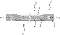
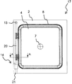
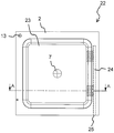
도 1a/도 1b 에 도시된 본 발명에 따른 제 1 리세스 플레이트 (1) 는 제 1 여과기 디바이스의 정지 헤드 피스와 이동 가능한 단부 피스 사이에서의 팩 (소위 "콤비 팩") 내에 제 1 리세스 플레이트 (1) 의 복수의 견본들만을 팩킹하기 위해 구성되고, 제 1 여과기 디바이스는 현탁액으로부터 고형분을 여과기 케이크로서 여과하기 위해 제 1 리세스 플레이트 (1) 의 인접한 견본들 사이에 두개의 여과포를 갖는다. 제 1 여과기 디바이스, 그 헤드 및 단부 피스들, 제 1 리세스 플레이트 (1) 의 견본들의 팩 및 여과포들은 도시 생략된다. The
제 1 리세스 플레이트 (1) 는 PP 로 제조된 베이스 본체 (2) 를 갖고, 베이스 본체 (2) 의 제 1 면 (3) 에서 제 1 리세스 (4) 를 갖고 제 2 면 (5) 에서 제 2 리세스 (6) 를 갖고, 팩에서, 제 1 리세스 플레이트 (1) 의 인접한 견본들의 제 1 리세스 (4) 및 제 2 리세스 (6) 는 여과기 챔버를 형성한다. 제 1 리세스 플레이트 (1) 의 제 1 리세스 (4) 및 제 2 리세스 (6) 를 제외하고, 여과기 챔버는 도시 생략된다. The
제 1 리세스 플레이트 (1) 는 관통 구멍 (7) 을 갖고, 팩에서 제 1 리세스 플레이트 (1) 의 견본들의 관통 구멍들 (7) 은 헤드로부터 여과기 챔버들 내로 그리고 각각의 여과포들 사이로 현탁액을 공급하기 위한 현탁액 파이프를 형성한다. 제 1 리세스 플레이트 (1) 의 관통 구멍 (7) 을 제외하고, 현탁액 파이프는 도시 생략된다. The
제 1 리세스 플레이트 (1) 는 제 1 리세스 (4) 주위에 밀봉된 이동 가능한 멤브레인 (8) 을 갖고, 멤브레인 (8) 및 제 1 리세스 플레이트 (1) 는 압착 챔버를 둘러싸고 리세스 플레이트 (1) 는 여과기 케이크로부터 남아 있는 유체를 기계적으로 가압하기 위해 압착 챔버 내로 압착 유체를 충전하기 위한 유입구 덕트를 갖는다. 압착 유체를 위한 유입구 덕트 및 압착 챔버는 도시 생략된다. The
제 1 리세스 플레이트 (1) 는 제 1 리세스 (4) 로부터 현탁액의 액체분을 여과액으로서 배출하기 위한 주변부로의 제 1 덕트 (9) 와 제 1 유출구 (10) 및 제 2 리세스 (6) 로부터 여과액을 배출하기 위한 주변부로의 제 2 덕트 (11) 와 제 2 유출구 (12) 를 추가로 갖는다. 제 1 덕트 (9) 는 관통 구멍 (13) 에 연결되고, 제 1 리세스 플레이트 (1) 의 인접한 견본들의 관통 구멍들 (13) 은 제 1 덕트 (9) 내로 세정 액체 및 건조 가스를 공급하기 위한 공급 파이프를 형성한다. 제 1 리세스 플레이트 (1) 의 관통 구멍들 (13) 을 제외하고, 공급 파이프는 도시 생략된다. The
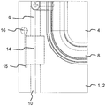
제 1 리세스 플레이트 (1) 는 도 1c 에 상세하게 도시되는 밸브 (14) 를 추가로 갖는다. 밸브 (14) 는 공압으로 구동되는 멤브레인, 즉 주변부로 제 1 덕트 (9) 를 개방하기 위한 핀치 밸브이다. 제 1 리세스 플레이트 (1) 는 밸브 (14) 용 제어 도관 (15) 및 제어 도관 (15) 에 연결된 관통 구멍 (16) 을 추가로 갖고, 제 1 여과기 디바이스에서, 제 1 리세스 플레이트 (1) 의 인접한 견본들의 관통 구멍들 (16) 은 헤드 피스로의 제어 파이프를 형성한다. 제 1 리세스 플레이트 (1) 의 관통 구멍 (16) 을 제외하고, 제어 파이프는 도시 생략된다. The
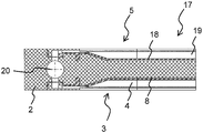
도 2a/도 2b 에 도시된 본 발명에 따른 제 2 리세스 플레이트 (17) 는 도 1a/도 1b 에 도시된 바와 같은 제 1 리세스 플레이트 (1) 와 기본적으로 유사하다. 제 1 리세스 플레이트 (1) 에 따른 제 2 리세스 플레이트 (17) 의 기본적으로 동일한 특징들은 마킹되어 있다. The
제 1 리세스 플레이트 (1) 와 상이하게, 제 2 리세스 플레이트 (17) 는 제 2 리세스 (19) 주위에 밀봉된 제 2 이동 가능한 멤브레인 (18) 을 갖고, 제 2 멤브레인 (18) 및 제 2 리세스 플레이트 (17) 는 제 2 압착 챔버를 둘러싸고 제 2 리세스 플레이트 (17) 는 제 2 압착 챔버 내로 압착 유체를 삽입하기 위한 제 2 유입구 덕트를 갖는다. 또한, 압착 유체를 위한 유입구 덕트 및 압착 챔버는 도시 생략된다. Unlike the
추가로 제 1 리세스 플레이트 (1) 와 다르게, 제 2 리세스 플레이트 (17) 에서 양쪽 제 1 리세스 (4) 및 제 2 리세스 (19) 는 여과액을 배출하기 위한 공통의 제 1 덕트 (20) 및 제 1 유출구 (21) 에 연결된다. 제 2 리세스 플레이트 (17) 는 여과액을 배출하기 위한 제 2 덕트를 갖지 않는다. In addition, unlike the
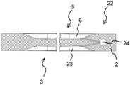
도 3a/도 3b 에 도시된 제 3 리세스 플레이트 (22) 는 도 1a/도 1b 에 도시된 바와 같은 제 1 리세스 플레이트 (1) 와 또한 기본적으로 유사하다. 제 1 리세스 플레이트 (1) 에 따른 제 3 리세스 플레이트 (22) 의 기본적으로 동일한 특징들은 마킹되어 있다. The
제 1 리세스 플레이트 (1) 와 상이하게, 제 3 리세스 플레이트 (22) 는 이동 가능한 멤브레인을 갖지 않는다. 추가로 제 1 리세스 플레이트 (1) 와 상이하게, 제 3 리세스 플레이트 (22) 는 여과액을 배출하기 위한 제 1 덕트를 갖지 않는다. 제 3 리세스 플레이트 (22) 에서 양쪽 제 1 리세스 (23) 및 제 2 리세스 (6) 는 여과액을 배출하기 위한 공통의 제 2 덕트 (24) 및 제 2 유출구 (25) 에 연결된다. 본 발명에 따른 제 2 여과기 디바이스에서, 제 2 리세스 플레이트 (17) 의 견본들 및 제 3 리세스 플레이트 (22) 의 견본들은 팩 (소위 "혼합형 팩") 에서 교대한다. Unlike the
본 발명에 따른 제 3 여과기 디바이스의 팩은 제 2 리세스 플레이트 (17) 및 제 3 리세스 플레이트 (22) 와 유사하지만 어느쪽의 리세스에서도 멤브레인을 갖는 제 4 리세스 플레이트 (소위 "풀 멤브레인 팩") 의 교대 순서를 포함한다. 본 발명에 따른 제 4 여과기 디바이스의 팩은 제 2 리세스 플레이트 (17) 와 유사하지만, 멤브레인들을 갖지 않는 본 발명에 따른 제 5 리세스 플레이트와 제 3 리세스 플레이트 (소위 "풀 챔버 팩") 의 교대 순서를 포함한다. 제 3 및 제 4 여과기 디바이스들과 제 4 및 제 5 리세스 플레이트들은 도시 생략된다. The pack of the third filter device according to the present invention is similar to the second and
본 발명에 따른 방법에서 제 1 내지 제 4 여과기 디바이스들을 작동시킬 때에, 처음에 현탁액은 현탁액 파이프를 통해 여과기 챔버들 내로 그리고 각각의 여과포들 사이로 공급된다. 현탁액의 고형분은 여과포들 사이에 침강되고, 현탁액의 액체분은 여과포들을 투과하고 제 1 덕트들 (9, 20) 을 통해 그리고 제 2 덕트들 (11, 24) 을 통해 여과기 챔버들로부터 여과액으로서 배출된다. 여과기 디바이스는 그 후에 현탁액 공급부로부터 차단되고, 밸브들 (14) 은 가압된 공기를 제어 파이프에 공급함으로써 폐쇄된다. In operating the first through fourth filter devices in the method according to the invention, the suspension is initially fed into the filter chambers through the suspension pipe and into the respective filter cloths. The solids of the suspension are settled between the filter cloths and the liquid fraction of the suspension is passed through the filter cloths and passed through the
그 후에, 제 1 내지 제 3 여과기 디바이스들을 작동시킬 때에, 압착 챔버들은 유입구 덕트들을 통해 압착 유체, 즉 워터로써 채워진다. 멤브레인들 (8, 18) 은 압착 유체에 의해 여과기 챔버들 내에 힘이 가해지고 여과기 케이크로부터 남아 있는 현탁액을 압착시킨다. 압착 챔버들은 압착 유체 공급부로부터 차단되고 압착 유체를 배출하기 위해 개방된다. Thereafter, when operating the first through third filter devices, the compression chambers are filled with compression fluid, i.e. water, through the inlet ducts. The
그 후에, 여과기 챔버들에는 공급 파이프를 통해 그리고 제 1 덕트들 (9, 20) 를 통해 세정 액체, 즉 워터가 공급된다. 세정 액체는 중간에서 여과기 케이크들 및 여과포들을 투과하고, 제 2 덕트들 (11, 24) 을 통해 배출된다. 단계 변화 조건 (step change condition) 에서, 여과기 디바이스는 세정 액체로부터 차단된다. Thereafter, the filter chambers are supplied with a cleaning liquid, i. E. Water, through a supply pipe and through the first ducts (9, 20). The cleaning liquid passes through the filter cakes and filter cloths in the middle, and is discharged through the second ducts (11, 24). In a step change condition, the filter device is shut off from the cleaning liquid.
그 후에 또한, 제 1 내지 제 3 여과기 디바이스들을 작동시킬 때에, 압착 챔버들은 여과기 케이크로부터 남아 있는 세정 액체를 압착하기 위해 압착 유체로써 채워진다. 압착 챔버들은 압착 유체 공급부로부터 차단되고 압착 유체를 배출하기 위해 개방된다. Thereafter, also when operating the first to third filter devices, the compression chambers are filled with a squeezing fluid to squeeze the remaining cleaning liquid from the filter cake. The compression chambers are disconnected from the compression fluid supply and open to discharge the compression fluid.
동시에 여과기 챔버들에는 제 1 덕트들 (9, 20) 을 통해 프로세스 공기가 공급된다. 건조 가스는 중간에서 여과기 케이크들 및 여과포를 투과하고 제 2 덕트들 (11, 24) 를 통해 배출된다. 단계 변화 조건에서, 여과기 디바이스는 건조 가스로부터 차단된다. At the same time, the filter chambers are supplied with process air through the first ducts (9, 20). The dry gas passes through the filter cakes and filter cloth in the middle and is discharged through the second ducts (11, 24). In the step change condition, the filter device is shut off from the drying gas.
마지막으로, 단부 플레이트는 해제되고 여과기 디바이스 및 팩은 여과기 케이크들을 언로드하기 (unloading) 위해, 여과포들, 멤브레인들 (8, 18) 및 리세스 플레이트들 (1, 17, 22), 특히 여과기 챔버들을 세척하고 변경하기 위해, 그리고 또 다른 사이클을 위해 개방된다. Finally, the end plates are released and the filter device and the packs are removed from the filter cloths, the
1 리세스 플레이트
2 베이스 본체
3 면
4 리세스
5 면
6 리세스
7 관통 구멍
8 멤브레인
9 덕트
10 유출구
11 덕트
12 유출구
13 관통 구멍
14 밸브
15 제어 도관
16 관통 구멍
17 리세스 플레이트
18 멤브레인
19 리세스
20 덕트
21 유출구
22 리세스 플레이트
23 리세스
24 덕트
25 유출구1 recess plate
2 base body
3 sides
4 recess
5th
6 recess
7 through hole
8 membrane
9 duct
10 outlet
11 duct
12 outlet
13 Through hole
14 valves
15 control conduit
16 through holes
17 recess plate
18 membrane
19 recess
20 duct
21 outlet
22 recess plate
23 recess
24 ducts
25 outlet
Claims (13)
상기 여과기 디바이스는 정지 헤드 피스와 이동 가능한 단부 피스 사이에, 적어도 제 1 리세스 (4, 19) 를 갖는 제 1 리세스 플레이트 (1, 17) 및/또는 제 2 리세스 (6, 23) 를 갖는 제 2 리세스 플레이트 (1, 22) 의 팩을 갖고,
상기 제 1 리세스 (4, 19) 및/또는 상기 제 2 리세스 (6, 23) 는 상기 제 1 리세스 플레이트 (1, 17) 와 상기 제 2 리세스 플레이트 (1, 22) 사이에 여과기 챔버를 형성하고,
상기 여과기 디바이스는 상기 현탁액으로부터 고형분을 여과기 케이크로서 여과하기 위해 상기 제 1 리세스 플레이트 (1, 17) 와 상기 제 2 리세스 플레이트 (1, 22) 사이에 두개의 여과포들을 갖고,
상기 제 1 리세스 플레이트 (1, 17) 는 제 1 유출구 (10, 21) 를 향하는 제 1 덕트 (9, 20) 를 갖고 상기 제 2 리세스 플레이트 (1, 22) 는 제 2 유출구 (12, 25) 를 향하는 제 2 덕트 (11, 24) 를 갖고,
상기 현탁액을 여과하기 위한 방법은,
a. 상기 여과포들 사이에서의 상기 여과기 챔버 내로 상기 현탁액을 공급하는 (piping) 단계,
b. 상기 여과기 케이크가 상기 여과포들 사이에서 침강 (settle) 하도록 상기 여과포들을 통해 상기 현탁액을 지향시키는 단계,
c. 상기 여과기 챔버로부터 상기 제 1 덕트 (9, 20) 및 상기 제 2 덕트 (11, 24) 를 통해 그리고 상기 제 1 리세스 플레이트 (1, 17) 로부터 상기 제 1 유출구 (10, 21) 및 상기 제 2 리세스 플레이트 (1, 22) 로부터 상기 제 2 유출구 (12, 25) 를 통해 상기 현탁액의 액체분을 여과액으로서 배출하는 단계, 및
d. 상기 헤드 피스로부터 상기 여과기 챔버 내로 상기 제 1 덕트 (9, 20) 를 통해 건조 가스를 공급하고 상기 제 2 덕트 (11, 24) 를 통해 상기 건조 가스를 배출하는 단계를 포함하는 일련의 단계들을 포함하고,
상기 제 2 덕트 (11, 24) 로부터 주변부로 곧장 상기 건조 가스를 배출하는 것을 특징으로 하는, 현탁액을 여과하기 위한 방법. CLAIMS 1. A method for filtering a suspension in a filter device,
The filter device comprises a first recess plate (1, 17) and / or a second recess (6, 23) having at least a first recess (4, 19) between the stop head piece and the movable end piece Having a second recess plate (1, 22)
The first and second recesses (4, 19) and / or the second recesses (6, 23) are arranged between the first and second recess plates (1, 17) Forming a chamber,
Said filter device having two filter beds between said first and second recess plates (1, 17) and said second recess plate (1, 22) for filtering solids from said suspension as filter cake,
The first and second recess plates 1 and 17 have first ducts 9 and 20 directed toward the first outlet 10 and 21 and the second recess plates 1 and 22 are connected to the second outlet 12, 25 facing the first and second ducts 11, 24,
The method for filtering the suspension comprises:
a. Piping the suspension into the filter chamber between the filter cloths,
b. Directing the suspension through the filter cloths such that the filter cake settle between the filter cloths,
c. (10, 21) and said second duct (11, 24) from said filter chamber through said first duct (9, 20) and said second duct Discharging the liquid fraction of the suspension from the two recess plates (1, 22) through the second outlets (12, 25) as a filtrate, and
d. Supplying a drying gas through the first duct (9, 20) from the headpiece into the filter chamber and discharging the drying gas through the second duct (11, 24) and,
Characterized in that the drying gas is discharged straight from the second duct (11, 24) to the periphery.
상기 제 1 덕트 (9, 20) 및 상기 제 2 덕트 (11, 24) 를 통해 상기 주변부로 곧장 상기 여과액을 배출하고, 상기 방법은 상기 여과기 챔버 내로 상기 건조 가스를 공급하기 전에 상기 주변부에 대해 상기 제 1 덕트 (9, 20) 를 폐쇄하는 단계를 추가로 포함하는 것을 추가로 특징으로 하는, 현탁액을 여과하기 위한 방법.The method according to claim 1,
The filtrate is discharged straight to the periphery through the first duct (9, 20) and the second duct (11, 24), the method comprising the steps of: The method of claim 1, further comprising closing the first duct (9, 20).
상기 건조 가스를 공급하기 전에, 이동 가능한 멤브레인 (8, 18) 과 상기 제 1 리세스 플레이트 (1, 17) 사이에서의 압착 챔버 내로 압착 유체를 충전함으로써 상기 여과기 케이크로부터 남아 있는 액체를 기계적으로 가압하는 단계를 추가로 포함하는, 현탁액을 여과하기 위한 방법.3. The method according to claim 1 or 2,
Prior to feeding the drying gas, the remaining liquid from the filter cake is mechanically pressurized by filling the pressurized fluid into the pressurized chamber between the movable membrane (8, 18) and the first recess plate (1, 17) ≪ / RTI > further comprising the step of filtering the suspension.
상기 건조 가스를 공급하기 전에, 상기 헤드 피스로부터 상기 여과기 챔버 내로 상기 제 1 덕트 (9, 20) 를 통해 세정 액체를 공급하고 상기 제 2 덕트 (11 , 24) 를 통해 상기 세정 액체를 배출하는 단계를 추가로 포함하는, 현탁액을 여과하기 위한 방법.4. The method according to any one of claims 1 to 3,
Supplying cleaning liquid from the headpiece through the first ducts (9, 20) into the filter chamber and discharging the cleaning liquid through the second ducts (11, 24) before supplying the drying gas ≪ / RTI > further comprising the step of filtering the suspension.
상기 리세스 플레이트는 여과기 디바이스의 정지 헤드 피스와 이동 가능한 단부 피스 사이에서의 팩 내에 상기 리세스 플레이트 (1, 17) 의 복수의 견본들을 팩킹하도록 구성되고,
상기 리세스 플레이트 (1, 17) 는 제 1 리세스 (4, 19) 를 갖고 그리고/또는 상기 여과기 디바이스에서 인접한 리세스 플레이트 (1, 22) 는 제 2 리세스 (6, 23) 를 갖고, 상기 제 1 리세스 (4, 19) 및/또는 상기 제 2 리세스 (6, 23) 는 상기 리세스 플레이트 (15) 와 상기 인접한 리세스 플레이트 (1, 22) 사이에 여과기 챔버를 형성하고,
상기 여과기 디바이스는 현탁액으로부터 고형분을 여과기 케이크로서 여과하기 위해 상기 리세스 플레이트 (1, 17) 와 상기 인접한 리세스 플레이트 (1, 22) 사이의 두개의 여과포들을 갖고,
상기 리세스 플레이트 (1, 17) 는 상기 여과기 챔버로부터 상기 현탁액의 액체분을 여과액으로서 배출하기 위한 덕트 및 주변부로 상기 덕트를 개방하기 위한 밸브 (14) 를 갖고,
상기 밸브 (14) 는 상기 리세스 플레이트 (1, 17) 에 내포되는 (nested), 리세스 플레이트 (1 , 17).As the recess plates (1, 17)
Said recess plate being configured to pack a plurality of specimens of said recess plate (1, 17) in a pack between a stop head piece and a moveable end piece of a strainer device,
Characterized in that the recess plate (1, 17) has a first recess (4, 19) and / or the adjacent recess plate (1, 22) in the strainer device has a second recess (6, 23) The first and second recesses (4, 19) and / or the second recesses (6, 23) form a filter chamber between the recess plate (15) and the adjacent recess plate (1, 22)
Said filter device having two filter beds between said recess plate (1, 17) and said adjacent recess plate (1, 22) for filtering solids from said suspension as filter cake,
Wherein the recess plate (1, 17) has a duct for discharging the liquid fraction of the suspension from the filter chamber as filtrate and a valve (14) for opening the duct to the periphery,
The valve (14) is nested in the recess plate (1, 17).
상기 밸브 (14) 용 제어 도관 (15) 을 추가로 특징으로 하는, 리세스 플레이트 (1 , 17).6. The method of claim 5,
Characterized in that it further comprises a control conduit (15) for said valve (14).
상기 제어 도관 (15) 에 연결된 관통 구멍 (16) 을 추가로 특징으로 하고,
상기 여과기 디바이스에서 상기 리세스 플레이트 (1, 17) 의 상기 견본들의 상기 관통 구멍들 (16) 은 상기 헤드 피스로의 제어 파이프를 형성하는, 리세스 플레이트 (1, 17).The method according to claim 6,
Characterized by further comprising a through hole (16) connected to said control conduit (15)
Wherein the through-holes (16) of the specimens of the recess plate (1, 17) in the filter device form a control pipe to the headpiece.
상기 밸브 (14) 는 공압으로 구동되는 멤브레인 것을 추가로 특징으로 하는, 리세스 플레이트 (1, 17).8. The method according to any one of claims 5 to 7,
The valve (14) is further characterized by a pneumatically driven membrane.
상기 밸브 (14) 는 핀치 밸브 (14) 인 것을 추가로 특징으로 하는, 리세스 플레이트 (1, 17).9. The method of claim 8,
Characterized in that the valve (14) is a pinch valve (14).
상기 여과기 챔버 주위로 밀봉되는 이동 가능한 멤브레인 (8, 18) 를 추가로 특징으로 하고,
상기 이동 가능한 멤브레인 (8, 18) 및 상기 리세스 플레이트 (1, 17) 는 압착 챔버를 둘러싸고 상기 리세스 플레이트 (1, 17) 는 상기 여과기 케이크로부터 남아 있는 유체를 기계적으로 가압하기 위해 상기 압착 챔버 내로 압착 유체를 충전하기 위한 유입구 덕트를 갖는, 리세스 플레이트 (1, 17).10. The method according to any one of claims 5 to 9,
Characterized by further comprising a movable membrane (8, 18) sealed around said filter chamber,
Characterized in that said movable membrane (8,18) and said recess plate (1, 17) surround a compression chamber and said recess plate (1, 17) (1, 17) having an inlet duct for filling a squeezing fluid into the interior of the recess plate.
상기 여과기 챔버에 대향하는 면 (3) 에서 제 2 이동 가능한 멤브레인 (18) 을 추가로 특징으로 하고,
상기 제 2 이동 가능한 멤브레인 (18) 은 제 2 여과기 챔버 주위에 밀봉되고,
상기 제 2 이동 가능한 멤브레인 (18) 및 상기 리세스 플레이트 (17) 는 제 2 압착 챔버를 둘러싸고 상기 리세스 플레이트 (17) 는 상기 제 2 압착 챔버 내로 압착 유체를 삽입하기 위한 제 2 유입구 덕트를 갖는, 리세스 플레이트 (17).11. The method of claim 10,
Characterized by further comprising a second movable membrane (18) at a face (3) opposite said filter chamber,
The second movable membrane (18) is sealed around a second filter chamber,
Wherein the second movable membrane (18) and the recess plate (17) surround a second compression chamber and the recess plate (17) has a second inlet duct for inserting a pressurized fluid into the second compression chamber , And a recess plate (17).
상기 여과기 디바이스는 정지 헤드 피스와 이동 가능한 단부 피스 사이에 적어도 제 1 리세스 플레이트 (1, 17) 및 제 2 리세스 플레이트 (1, 22) 의 팩을 갖고,
상기 제 1 리세스 플레이트 (1, 17) 는 제 1 리세스 (4, 19) 를 갖고 그리고/또는 상기 제 2 리세스 플레이트 (1, 22) 는 제 2 리세스 (6, 23) 를 갖고,
상기 제 1 리세스 (4, 19) 및/또는 상기 제 2 리세스 (6, 23) 는 상기 제 1 리세스 플레이트 (1, 17) 와 상기 제 2 리세스 플레이트 (1, 22) 사이에 여과기 챔버를 형성하고,
상기 여과기 디바이스는 상기 현탁액으로부터 고형분을 여과기 케이크로서 여과하기 위해 상기 제 1 리세스 플레이트 (1, 17) 와 상기 제 2 리세스 플레이트 (1, 22) 사이에 두개의 여과포를 갖고,
상기 제 1 리세스 플레이트 (1, 17) 는 제 1 유출구 (10, 21) 를 향하는 제 1 덕트 (9, 20) 를 갖고 상기 제 2 리세스 플레이트 (1, 22) 는 제 2 유출구 (12, 25) 를 향하는 제 2 덕트 (11, 24) 를 갖고,
제 5 항 내지 제 12 항 중 어느 한 항에 따른 적어도 상기 제 1 리세스 플레이트 (1, 17) 를 특징으로 하는, 여과기 디바이스.As a filter device,
The filter device has a pack of at least a first recess plate (1, 17) and a second recess plate (1, 22) between the stop head piece and the movable end piece,
Wherein the first recess plate has a first recess and the second recess plate has a second recess,
The first and second recesses (4, 19) and / or the second recesses (6, 23) are arranged between the first and second recess plates (1, 17) Forming a chamber,
Said filter device having two filterbags between said first and second recess plates (1, 17) and said second recess plate (1, 22) for filtering solids from said suspension as filter cake,
The first and second recess plates 1 and 17 have first ducts 9 and 20 directed toward the first outlet 10 and 21 and the second recess plates 1 and 22 are connected to the second outlet 12, 25 facing the first and second ducts 11, 24,
A filter device characterized by at least said first recess plate (1, 17) according to any one of claims 5 to 12.
팩에서 교대하는 제 11 항에 따른 리세스 플레이트들 (17) 및 다른 리세스 플레이트들 (22) 을 추가로 특징으로 하는, 여과기 디바이스.13. The method of claim 12,
Characterized in that it further features the recess plates (17) and other recess plates (22) according to claim 11 alternating in the pack.
Applications Claiming Priority (1)
| Application Number | Priority Date | Filing Date | Title |
|---|---|---|---|
| PCT/EP2012/057186 WO2013156070A1 (en) | 2012-04-19 | 2012-04-19 | Method for filtering a suspension and recess plate |
Publications (1)
| Publication Number | Publication Date |
|---|---|
| KR20140147125A true KR20140147125A (en) | 2014-12-29 |
Family
ID=45976405
Family Applications (1)
| Application Number | Title | Priority Date | Filing Date |
|---|---|---|---|
| KR1020147031383A KR20140147125A (en) | 2012-04-19 | 2012-04-19 | Method for filtering a suspension and recess plate |
Country Status (15)
| Country | Link |
|---|---|
| US (1) | US9776109B2 (en) |
| EP (1) | EP2838638B1 (en) |
| JP (1) | JP2015517906A (en) |
| KR (1) | KR20140147125A (en) |
| CN (2) | CN108837567B (en) |
| AU (1) | AU2012377126C1 (en) |
| BR (1) | BR112014025453B8 (en) |
| CA (1) | CA2867629C (en) |
| CL (1) | CL2018000423A1 (en) |
| EA (1) | EA028296B1 (en) |
| ES (1) | ES2672126T3 (en) |
| MX (1) | MX2014012471A (en) |
| TR (1) | TR201807623T4 (en) |
| UA (1) | UA109999C2 (en) |
| WO (1) | WO2013156070A1 (en) |
Families Citing this family (3)
| Publication number | Priority date | Publication date | Assignee | Title |
|---|---|---|---|---|
| CN109475794B (en) * | 2016-07-11 | 2022-03-15 | 奥图泰(芬兰)公司 | Horizontal pressure filter with wash liquor recovery, filtration system related thereto, method of operation and computer program product |
| RU2686905C1 (en) * | 2018-10-24 | 2019-05-06 | Сергей Леонидович Филатов | Filter plate for filter press |
| CN114146461A (en) * | 2021-12-10 | 2022-03-08 | 湖北省轻工业科学研究设计院有限公司 | Novel filter plate structure of filter press |
Family Cites Families (24)
| Publication number | Priority date | Publication date | Assignee | Title |
|---|---|---|---|---|
| US1441445A (en) * | 1919-04-29 | 1923-01-09 | United Filters Corp | Filter plate |
| US1342839A (en) * | 1919-06-23 | 1920-06-08 | Harry T Shriver | Filter |
| CH399422A (en) | 1962-05-28 | 1965-09-30 | Ciba Geigy | Filter press |
| GB2189403B (en) * | 1986-04-21 | 1989-11-29 | Steetley Refractories Ltd | Method of and apparatus for filtering a slurry |
| JP3016751B2 (en) * | 1997-07-10 | 2000-03-06 | 株式会社栗田機械製作所 | Squeezed plate in squeezed filter press |
| US6180002B1 (en) * | 1998-08-03 | 2001-01-30 | United States Filter Corporation | Filter press with alternating diaphragm squeeze chamber plates and filtration chamber plates |
| RU2156639C1 (en) * | 1999-07-06 | 2000-09-27 | Потапов Олег Аркадьевич | Method and press-filter for dehydration of aqueous suspension |
| JP2001224910A (en) * | 2000-02-17 | 2001-08-21 | Ishigaki Co Ltd | Method for releasing stuck cake in filter press |
| CN2472787Y (en) * | 2001-04-04 | 2002-01-23 | 朱兴源 | Nesting type diaphragm filter plate |
| JP2003136099A (en) * | 2002-08-30 | 2003-05-13 | Tsukishima Kikai Co Ltd | Sludge dehydration method |
| JP3773192B2 (en) * | 2002-08-30 | 2006-05-10 | 月島機械株式会社 | Sludge dewatering method |
| US20060032805A1 (en) * | 2002-09-13 | 2006-02-16 | Hildebrant Mark W | Heating plate for vacuum filter press |
| JP3773193B2 (en) * | 2002-09-26 | 2006-05-10 | 月島機械株式会社 | Filter press apparatus and sludge dewatering method |
| DE10331383A1 (en) * | 2003-07-11 | 2005-02-10 | E. Begerow Gmbh & Co | Device for filtering fluids |
| JP2005131508A (en) * | 2003-10-29 | 2005-05-26 | Tsukishima Kikai Co Ltd | Filter cloth deposition cake removal method in dehydration using filter cloth, dehydration method by filter press and filter press device |
| CN2706217Y (en) * | 2004-05-20 | 2005-06-29 | 周明远 | Suspension liquid material filter pressing drying dewatering equipment |
| CN1297334C (en) * | 2004-05-20 | 2007-01-31 | 周明远 | Thermal pressure filtration process for deep dehydration of fine coal suspension liquid and apparatus therefor |
| JP2006223946A (en) * | 2005-02-15 | 2006-08-31 | Unozawa Gumi Iron Works Ltd | Filter press apparatus and slurry pressing method of slurry in the same |
| JP4497475B2 (en) * | 2005-03-08 | 2010-07-07 | 月島機械株式会社 | Filter press equipment |
| CN2869488Y (en) * | 2006-01-20 | 2007-02-14 | 深圳迈瑞生物医疗电子股份有限公司 | Pneumatic pressure cut-off valve |
| CN201076786Y (en) * | 2007-06-26 | 2008-06-25 | 梁建国 | Filtration washing dehydration drying device for micro sized particles |
| CN101332372A (en) * | 2007-06-29 | 2008-12-31 | 上海奇谋能源技术开发有限公司 | Entirety type pressure filter with pressing function |
| DE102007062102A1 (en) * | 2007-12-21 | 2009-06-25 | Mahle International Gmbh | filtering device |
| PT104494B (en) * | 2009-04-06 | 2010-03-25 | Inst Superior Tecnico | INTEGRATED FILTRATION, COMPRESSION AND VACUUM UNIT FOR INTEGRATED PROCESS OF FILTRATION, COMPRESSION AND DRYING VACUUM OF THE CERAMIC INDUSTRY DRÊCHE, AND RESPECTIVE APPLICATION OF THE FINAL PRODUCTS |
-
2012
- 2012-04-19 JP JP2015506103A patent/JP2015517906A/en not_active Ceased
- 2012-04-19 UA UAA201410516A patent/UA109999C2/en unknown
- 2012-04-19 BR BR112014025453A patent/BR112014025453B8/en active IP Right Grant
- 2012-04-19 ES ES12715111.6T patent/ES2672126T3/en active Active
- 2012-04-19 CN CN201810639985.0A patent/CN108837567B/en active Active
- 2012-04-19 EP EP12715111.6A patent/EP2838638B1/en active Active
- 2012-04-19 KR KR1020147031383A patent/KR20140147125A/en not_active Application Discontinuation
- 2012-04-19 MX MX2014012471A patent/MX2014012471A/en unknown
- 2012-04-19 CN CN201280072454.9A patent/CN104302376A/en active Pending
- 2012-04-19 AU AU2012377126A patent/AU2012377126C1/en active Active
- 2012-04-19 TR TR2018/07623T patent/TR201807623T4/en unknown
- 2012-04-19 WO PCT/EP2012/057186 patent/WO2013156070A1/en active Application Filing
- 2012-04-19 EA EA201491798A patent/EA028296B1/en not_active IP Right Cessation
- 2012-04-19 US US14/394,495 patent/US9776109B2/en active Active
- 2012-04-19 CA CA2867629A patent/CA2867629C/en active Active
-
2018
- 2018-02-15 CL CL2018000423A patent/CL2018000423A1/en unknown
Also Published As
| Publication number | Publication date |
|---|---|
| WO2013156070A1 (en) | 2013-10-24 |
| ES2672126T3 (en) | 2018-06-12 |
| BR112014025453B8 (en) | 2023-02-07 |
| AU2012377126A1 (en) | 2014-10-30 |
| CN108837567B (en) | 2021-07-13 |
| AU2012377126B2 (en) | 2015-11-12 |
| CN108837567A (en) | 2018-11-20 |
| CA2867629A1 (en) | 2013-10-24 |
| TR201807623T4 (en) | 2018-06-21 |
| CN104302376A (en) | 2015-01-21 |
| JP2015517906A (en) | 2015-06-25 |
| BR112014025453B1 (en) | 2021-03-02 |
| BR112014025453A2 (en) | 2017-08-08 |
| EA028296B1 (en) | 2017-10-31 |
| AU2012377126C1 (en) | 2016-03-03 |
| CL2018000423A1 (en) | 2018-06-08 |
| CA2867629C (en) | 2017-11-07 |
| US9776109B2 (en) | 2017-10-03 |
| EP2838638A1 (en) | 2015-02-25 |
| UA109999C2 (en) | 2015-10-26 |
| EA201491798A1 (en) | 2015-03-31 |
| EP2838638B1 (en) | 2018-03-14 |
| US20150114914A1 (en) | 2015-04-30 |
| MX2014012471A (en) | 2015-03-13 |
Similar Documents
| Publication | Publication Date | Title |
|---|---|---|
| US7998354B2 (en) | Filter press with improved plate assembly and method of filtering | |
| KR20140147125A (en) | Method for filtering a suspension and recess plate | |
| WO2007104233A1 (en) | A filter press | |
| US20150108072A1 (en) | Method for sealing a filter chamber and filter device | |
| EP3433000A1 (en) | Horizontal pressure filter collector element, horizontal pressure filter plate element, horizontal pressure filter, and methods related thereto | |
| JP2015517906A5 (en) | ||
| US10252191B2 (en) | Method for air drying a filter cake and filter plate | |
| WO2000007487A1 (en) | Cylindrical filter | |
| AU2012377129B2 (en) | Filter device and method for filtering a suspension | |
| GB104673A (en) | Improvements in Filters. | |
| JP2021053577A (en) | Filter press | |
| GB191414976A (en) | Improvements in and relating to Pressing Apparatus for Separating Solids from Liquids and for other purposes. |
Legal Events
| Date | Code | Title | Description |
|---|---|---|---|
| A201 | Request for examination | ||
| E902 | Notification of reason for refusal | ||
| E601 | Decision to refuse application |