EP2838638B1 - Method for filtering a suspension and recess plate - Google Patents
Method for filtering a suspension and recess plate Download PDFInfo
- Publication number
- EP2838638B1 EP2838638B1 EP12715111.6A EP12715111A EP2838638B1 EP 2838638 B1 EP2838638 B1 EP 2838638B1 EP 12715111 A EP12715111 A EP 12715111A EP 2838638 B1 EP2838638 B1 EP 2838638B1
- Authority
- EP
- European Patent Office
- Prior art keywords
- recess
- recess plate
- filter
- duct
- plate
- Prior art date
- Legal status (The legal status is an assumption and is not a legal conclusion. Google has not performed a legal analysis and makes no representation as to the accuracy of the status listed.)
- Active
Links
- 239000000725 suspension Substances 0.000 title claims description 28
- 238000000034 method Methods 0.000 title claims description 24
- 238000001914 filtration Methods 0.000 title claims description 20
- 239000012528 membrane Substances 0.000 claims description 38
- 239000000706 filtrate Substances 0.000 claims description 28
- 238000001035 drying Methods 0.000 claims description 27
- 239000012065 filter cake Substances 0.000 claims description 23
- 239000012530 fluid Substances 0.000 claims description 20
- 239000007788 liquid Substances 0.000 claims description 18
- 238000007599 discharging Methods 0.000 claims description 17
- 238000005406 washing Methods 0.000 claims description 9
- 239000007787 solid Substances 0.000 claims description 7
- 238000012856 packing Methods 0.000 claims description 3
- 239000004744 fabric Substances 0.000 claims 1
- 239000004743 Polypropylene Substances 0.000 description 3
- 239000012466 permeate Substances 0.000 description 3
- 229920001155 polypropylene Polymers 0.000 description 3
- 238000004140 cleaning Methods 0.000 description 2
- XLYOFNOQVPJJNP-UHFFFAOYSA-N water Substances O XLYOFNOQVPJJNP-UHFFFAOYSA-N 0.000 description 2
- 229910000831 Steel Inorganic materials 0.000 description 1
- 239000004411 aluminium Substances 0.000 description 1
- 229910052782 aluminium Inorganic materials 0.000 description 1
- XAGFODPZIPBFFR-UHFFFAOYSA-N aluminium Chemical compound [Al] XAGFODPZIPBFFR-UHFFFAOYSA-N 0.000 description 1
- 239000007900 aqueous suspension Substances 0.000 description 1
- 230000007423 decrease Effects 0.000 description 1
- 230000003628 erosive effect Effects 0.000 description 1
- 229910052751 metal Inorganic materials 0.000 description 1
- 239000002184 metal Substances 0.000 description 1
- 239000000203 mixture Substances 0.000 description 1
- 239000004033 plastic Substances 0.000 description 1
- 229920003023 plastic Polymers 0.000 description 1
- -1 polypropylene Polymers 0.000 description 1
- 239000010959 steel Substances 0.000 description 1
- 230000000007 visual effect Effects 0.000 description 1
Images

Classifications
-
- B—PERFORMING OPERATIONS; TRANSPORTING
- B01—PHYSICAL OR CHEMICAL PROCESSES OR APPARATUS IN GENERAL
- B01D—SEPARATION
- B01D25/00—Filters formed by clamping together several filtering elements or parts of such elements
- B01D25/12—Filter presses, i.e. of the plate or plate and frame type
- B01D25/164—Chamber-plate presses, i.e. the sides of the filtering elements being clamped between two successive filtering plates
-
- B—PERFORMING OPERATIONS; TRANSPORTING
- B01—PHYSICAL OR CHEMICAL PROCESSES OR APPARATUS IN GENERAL
- B01D—SEPARATION
- B01D25/00—Filters formed by clamping together several filtering elements or parts of such elements
- B01D25/12—Filter presses, i.e. of the plate or plate and frame type
- B01D25/21—Plate and frame presses
- B01D25/215—Construction of the filter plates, frames
-
- B—PERFORMING OPERATIONS; TRANSPORTING
- B01—PHYSICAL OR CHEMICAL PROCESSES OR APPARATUS IN GENERAL
- B01D—SEPARATION
- B01D25/00—Filters formed by clamping together several filtering elements or parts of such elements
- B01D25/28—Leaching or washing filter cakes in the filter handling the filter cake for purposes other than regenerating
- B01D25/281—Leaching or washing filter cakes in the filter handling the filter cake for purposes other than regenerating specially for chamber filter presses
-
- B—PERFORMING OPERATIONS; TRANSPORTING
- B01—PHYSICAL OR CHEMICAL PROCESSES OR APPARATUS IN GENERAL
- B01D—SEPARATION
- B01D25/00—Filters formed by clamping together several filtering elements or parts of such elements
- B01D25/28—Leaching or washing filter cakes in the filter handling the filter cake for purposes other than regenerating
- B01D25/282—Leaching or washing filter cakes in the filter handling the filter cake for purposes other than regenerating for drying
- B01D25/284—Leaching or washing filter cakes in the filter handling the filter cake for purposes other than regenerating for drying by gases or by heating
Definitions
- the invention relates in general to filtering and in particular to a method for filtering a suspension in a filter device and to a recess plate.
- a filter chamber is formed between two adjacent recess plates by the recess of at least one of the recess plates. Filtrate is discharged from the filter chamber through outlets into two separate filtrate collecting ducts, leading back to a head piece of the filter device. A Drying gas is piped from the head piece through one of these filtrate collecting ducts and outlets into the filter chamber and discharged through the other duct and filtrate collecting duct back to the head piece.
- the drying gas is under pressure when piped into the filter chamber, and pushes the remaining liquid through a filter cake formed on a filter media in the filter chamber. After permeating the cake, the drying gas pressure falls down to ambient pressure and the drying gas expands, accordingly.
- the related filtrate collecting duct either requires significantly larger pipes than the duct that pipes the pressurized drying gas from the head piece to the filter chambers, or the expanded drying gas flows at a significantly higher speed. In the former case, the related pipe cross section is unavailable for the filter chamber and thus decreases filtration capacity of the filter device. In the latter case, the increased speed of gas flow causes erosion and wearing of the recess plate.
- Recess plates according to prior art have filtrate taps for manually opening the filtrate ducts to the ambience, for testing purposes, during a filtration cycle. Comparing opacity of the filtrate protruding from the taps provides for a simple but however qualitatively sensitive visual performance check of the related filter cloths. Moreover, in some filter devices according to prior art filtrate is always disposed straight from the filter chambers through the base body of the respective recess plates, to the ambience. However, such filter devices do not provide for drying the filter cake.
- Document WO 02/09842A1 discloses a method for dehydrating an aqueous suspension by filtration with the aid of a pressure filter. The drying of the deposit is carried out by using pressurised gas.
- the invention suggests a method for filtering a suspension in a filter device, the filter device having between a stationary head piece and a movable end piece a pack of at least a first recess plate having a first recess and/or a second recess plate having a second recess, the first recess and/or the second recess forming a filter chamber between the first recess plate and the second recess plate, and the filter device having two filter cloths between the first recess plate and the second recess plate for filtering a solid content out of the suspension as a filter cake, and the first recess plate having a first duct towards a first outlet and the second recess plate having a second duct towards a second outlet, the method comprising a sequence of steps, including piping the suspension into the filter chamber between the filter cloths, directing the suspension through the filter cloths, such that the filter cake settles between the filter cloths, discharging a liquid fraction of the suspension through the first duct and the second duct out
- a method according to the invention avoids the need for a collecting duct for the expanded drying gas.
- the pipe cross section that was in the state of the art provided for the expanded drying gas is available for other purpose, in particular for enlarging the filtration chamber, and thus the filtration capacity.
- the filtrate is discharged through the first and second ducts straight to the ambience, and the first duct is closed to the ambience prior to piping the drying gas into the filter chamber.
- Such method according to the invention further avoids the need for filtrate collecting ducts.
- the pipe cross section that was in the state of the art provided for collecting the filtrate is available for other purpose, in particular for enlarging the filtration chamber, and thus the filtration capacity.
- such filter device must provide means for piping the drying gas to the first ducts.
- a method according to the invention may be executed on a filter device piping the filtrate back to the head piece, in particular where the filtrate must be prevented from pollution.
- the recess plates have valves opening the second duct to the ambience, for the expanded drying gas.
- the pipe cross section of the filtrate collecting ducts only has to be sufficient for the filtrate, that protrudes from the filter chambers.
- a remaining liquid is mechanically pressed out of the filter cake by filling a squeezing fluid into a squeezing chamber between a movable membrane and the first recess plate. Making use of such movable membranes for pressing the filter cake is commonly known in the state of the art.
- a washing liquid is piped from the head piece into the filter chamber through the first duct and discharged through the second duct.
- the washing liquid may be piped to the first ducts and/or disposed through the second ducts using the same means that are provided for the drying gas, in the related filter device.
- the invention further suggests a recess plate, that is designed for packing a plurality of specimens of the recess plate into a pack between a stationary head piece and a movable end piece of a filter device, wherein the recess plate has a first recess and/or an adjacent recess plate in the filter device has a second recess, the first recess and/or the second recess forming a filter chamber between the recess plate and the adjacent recess plate, wherein the filter device has two filter cloths between the recess plate and the adjacent recess plate for filtering a solid content out of a suspension as a filter cake, and wherein the recess plate has a duct for discharging a liquid fraction of the suspension out of the filter chamber as a filtrate, and a valve for opening the duct to the ambience, and wherein a valve for opening the duct to the ambience is nested in the recess plate.
- a recess plate according to the invention allows for executing the above mentioned method according to the invention and is equally characterized by the advantages mentioned above.
- Recess plates according to the invention are made of plastics, e.g. polypropylene (PP), or of metal, e.g. aluminium or steel.
- a recess plate according to the invention has a control conduit for the valve.
- such recess plate has a through-hole, connected to the control conduit, wherein in a filter device, the through-holes of the specimens of the recess plate form a control pipe to the head piece.
- Operating the valves thus requires no external duct.
- the valve is a pneumatically driven membrane, preferably a pinch valve.
- a pneumatically driven membrane, in particular a pinch valve provides for a very simple and thus cheap valve type.
- the valve may be provided in a cartridge for easy replacement in case of failure.
- a recess plate according to the invention has a movable membrane sealed around the filter chamber, wherein the membrane and the recess plate enclose a squeezing chamber and the recess plate has an inlet duct for filling a squeezing fluid into the squeezing chamber, for mechanically pressing a remaining fluid out of the filter cake.
- movable membranes for pressing the filter cake is commonly known in the state of the art.
- Such a recess plate according to the invention may have a second movable membrane at a face opposite to the filter chamber, wherein the movable membrane is sealed around a second filter chamber, wherein the second membrane and the second recess plate enclose a second squeezing chamber and the recess plate has a second inlet duct for inserting a squeezing fluid into the second squeezing chamber.
- symmetrical recess plates are commonly known in the state of the art to be used alternating with other symmetrical recess plates, having no membranes (named “chamber plates”), in a pack of recess plates in a filter device.
- a filter device is suggested to have at least one recess plate having the features mentioned above, in particular to have a pack of recess plates, each having two movable membranes, as mentioned above, and other recess plates alternating in the pack (named "mix pack").
- a recess plate according to the invention may have two adjacent filter chambers, but only one face with a membrane.
- Such recess plates are commonly known in the state of the art to be used in sequence, in a pack of recess plates (named “combi pack”) in a filter device.
- the recess plates of the pack are vertically stacked on top of each other or hanging side by side.
- the filter device is secured by hydraulic force, by the weight of the stacked recess plates and/or by mechanical means.
- the filter chamber may be formed by two adjacent recesses, or by one single recess adjoining to a face of a recess plate with no recess.
- the pack may contain a sequence of identical recess plates in unchanging orientation, a sequence of identical recess plates in changing orientation or a sequence of alternating recess plates. Accordingly, recess plates may have two recesses, one recess or even no recess at all.
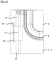
- the first recess plate 1 shown in figures 1a /b is designed for packing a plurality of only specimens of the first recess plate 1 into a pack (so-called "combi pack") between a stationary head piece and a movable end piece of a first filter device, wherein the first filter device has two filter cloths between adjacent specimens of the first recess plate 1 for filtering a solid content out of a suspension as a filter cake.
- the first filter device, it's head and end pieces, the pack of specimens of the first recess plate 1 and the filter cloths are not shown.
- the first recess plate 1 has a base body 2 made of PP, and in a first face 3 of the base body 2 has a first recess 4 and in a second face 5 a second recess 6, wherein in the pack, the first recess 4 and the second recess 6 of adjacent specimens of the first recess plate 1 form a filter chamber. Apart from the first recess 4 and the second recess 6 of the first recess plate 1, the filter chamber is not shown.
- the first recess plate 1 has a through-hole 7, wherein in the pack, the through-holes 7 of the specimens of the first recess plate 1 form a suspension pipe for piping the suspension from the head into the filter chambers, and between the respective filter cloths. Apart from the through-hole 7 of the first recess plate 1, the suspension pipe is not shown.
- the first recess plate 1 has a movable membrane 8 sealed around the first recess 4, wherein the membrane 8 and the first recess plate 1 enclose a squeezing chamber and the recess plate 1 has an inlet duct for filling a squeezing fluid into the squeezing chamber, for mechanically pressing a remaining fluid out of the filter cake.
- the squeezing chamber and the inlet duct for the squeezing fluid are not shown.
- the first recess plate 1 further has a first duct 9 and a first outlet 10 to the ambience for discharging a liquid fraction of the suspension out of the first recess 4 as a filtrate, and a second duct 11 and a second outlet 12 to the ambience for discharging the filtrate out of the second recess 6.
- the first duct 9 is connected to a through-hole 13, wherein the through-holes 13 of adjacent specimens of the first recess plate 1 form a supply pipe for piping the drying gas and the washing liquid into the first duct 9. Apart from the through-holes 13 of the first recess plate 1, the supply pipe is not shown.
- the first recess plate 1 further has a valve 14, that is in detail shown in figure 1c .
- the valve 14 is a pneumatically driven membrane, namely a pinch valve for opening the first duct 9 to the ambience.
- the first recess plate 1 further has a control conduit 15 for the valve 14, and a through-hole 16, connected to the control conduit 15, wherein in the first filter device, the through-holes 16 of adjacent specimens of the first recess plate 1 form a control pipe to the head piece. Apart from the through-hole 16 of the first recess plate 1, the control pipe is not shown.
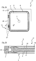
- the second recess plate 17 according to the invention basically resembles the first recess plate 1 as shown in figures 1a /b. Basically identical features of the second recess plate 17 are marked according to the first recess plate 1.
- the second recess plate 17 Differing from the first recess plate 1, the second recess plate 17 has a second movable membrane 18 sealed around the second recess 19, wherein the second membrane 18 and the second recess plate 17 enclose a second squeezing chamber and the second recess plate 17 has a second inlet duct for inserting a squeezing fluid into the second squeezing chamber.
- the squeezing chamber and the inlet duct for the squeezing fluid are not shown.
- both the first recess 4 and the second recess 19 are connected to a common first duct 20 and first outlet 21 for discharging the filtrate.
- the second recess plate 17 has no second duct for discharging the filtrate.
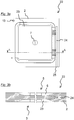
- the third recess plate 22 has no movable membrane. Further differing from the first recess plate 1, the third recess plate 22 has no first duct for discharging the filtrate. In the third recess plate 22 both the first recess 23 and the second recess 6 are connected to a common second duct 24 and second outlet 25 for discharging the filtrate. In a second filter device according to the invention, specimens of the second recess plate 17 and specimens of the third recess plate 22 are alternating in the pack (so-called "mixed pack").
- the pack of a third filter device according to the invention contains an alternating sequence of the second recess plate 17 and a fourth recess plate, that is similar to the third recess plate 22, but having membranes at either recess (so-called "full membrane pack”).
- the pack of a fourth filter device according to the invention contains an alternating sequence of a fifth recess plate according to the invention, that is similar to second recess plate 17, but having no membranes, a the third recess plate (so-called "full chamber pack”).
- the third and fourth filter devices and the fourth and fifth recess plates are not shown.
- first a suspension is piped through the suspension pipe into the filter chambers and between the respective filter cloths.
- the solid content of the suspension settles between the filter cloths, and the liquid fraction of the suspension permeates the same and discharges out of the filter chambers through the first ducts 9, 20, and through the second ducts 11, 24, as filtrate.
- the filter device is then disconnected from the suspension supply, and the valves 14 are closed by supplying the control pipe with pressurized air.
- the squeezing chambers are charged with a squeezing fluid, namely water, through the inlet ducts.
- a squeezing fluid namely water
- the membranes 8, 18 are forced into the filter chambers by the squeezing fluid, and squeezing the remaining suspension out of the filter cake.
- the squeezing chambers are disconnected from the squeezing fluid supply and opened for discharging the squeezing fluid.
- the filter chambers are supplied with a washing liquid, namely water, through the supply pipe and through the first ducts 9, 20.
- the washing liquid permeates the filter cloths and the filter cakes inbetween, and discharges through the second ducts 11, 24.
- the filter device is disconnected from the washing liquid.
- the squeezing chambers are charged with the squeezing fluid for squeezing the remaining washing liquid out of the filter cake.
- the squeezing chambers are disconnected from the squeezing fluid supply and opened for discharging the squeezing fluid.
- the filter chambers are supplied with process air through the first ducts 9, 20.
- the drying gas permeates the filter cloths and the filter cakes inbetween, and discharges through the second ducts 11, 24.
- the filter device is disconnected from the drying gas.
Description
- The invention relates in general to filtering and in particular to a method for filtering a suspension in a filter device and to a recess plate.
- In press filter devices and the like, a filter chamber is formed between two adjacent recess plates by the recess of at least one of the recess plates. Filtrate is discharged from the filter chamber through outlets into two separate filtrate collecting ducts, leading back to a head piece of the filter device. A Drying gas is piped from the head piece through one of these filtrate collecting ducts and outlets into the filter chamber and discharged through the other duct and filtrate collecting duct back to the head piece.
- The drying gas is under pressure when piped into the filter chamber, and pushes the remaining liquid through a filter cake formed on a filter media in the filter chamber. After permeating the cake, the drying gas pressure falls down to ambient pressure and the drying gas expands, accordingly. For piping the expanded drying gas from the filter chamber back to the head piece, the related filtrate collecting duct either requires significantly larger pipes than the duct that pipes the pressurized drying gas from the head piece to the filter chambers, or the expanded drying gas flows at a significantly higher speed. In the former case, the related pipe cross section is unavailable for the filter chamber and thus decreases filtration capacity of the filter device. In the latter case, the increased speed of gas flow causes erosion and wearing of the recess plate.
- Recess plates according to prior art have filtrate taps for manually opening the filtrate ducts to the ambience, for testing purposes, during a filtration cycle. Comparing opacity of the filtrate protruding from the taps provides for a simple but however qualitatively sensitive visual performance check of the related filter cloths. Moreover, in some filter devices according to prior art filtrate is always disposed straight from the filter chambers through the base body of the respective recess plates, to the ambience. However, such filter devices do not provide for drying the filter cake.
- Document
WO 02/09842A1 - Thus it is an object of the invention to increase filtration capacity of the known methods, recess plates and filter devices.
- The invention suggests a method for filtering a suspension in a filter device, the filter device having between a stationary head piece and a movable end piece a pack of at least a first recess plate having a first recess and/or a second recess plate having a second recess, the first recess and/or the second recess forming a filter chamber between the first recess plate and the second recess plate, and the filter device having two filter cloths between the first recess plate and the second recess plate for filtering a solid content out of the suspension as a filter cake, and the first recess plate having a first duct towards a first outlet and the second recess plate having a second duct towards a second outlet, the method comprising a sequence of steps, including piping the suspension into the filter chamber between the filter cloths, directing the suspension through the filter cloths, such that the filter cake settles between the filter cloths, discharging a liquid fraction of the suspension through the first duct and the second duct out of the filter chamber and through the first outlet of the first recess plate and the second outlet of the second recess plate as a filtrate, and piping a drying gas from the head piece into the filter chamber through the first duct and discharging the same through the second duct, and to discharge the drying gas straight from the second duct to the ambience. A method according to the invention avoids the need for a collecting duct for the expanded drying gas. In a filter device executing such method, the pipe cross section that was in the state of the art provided for the expanded drying gas, is available for other purpose, in particular for enlarging the filtration chamber, and thus the filtration capacity.
- Preferably, within a method according to the invention, the filtrate is discharged through the first and second ducts straight to the ambience, and the first duct is closed to the ambience prior to piping the drying gas into the filter chamber. Such method according to the invention further avoids the need for filtrate collecting ducts. In a filter device executing such method, the pipe cross section that was in the state of the art provided for collecting the filtrate, is available for other purpose, in particular for enlarging the filtration chamber, and thus the filtration capacity. However, such filter device must provide means for piping the drying gas to the first ducts.
- Alternatively, a method according to the invention may be executed on a filter device piping the filtrate back to the head piece, in particular where the filtrate must be prevented from pollution. For executing such method according to the invention, the recess plates have valves opening the second duct to the ambience, for the expanded drying gas. In the related filter device, the pipe cross section of the filtrate collecting ducts only has to be sufficient for the filtrate, that protrudes from the filter chambers.
- Further preferred, within a method according to the invention, prior to the drying gas, a remaining liquid is mechanically pressed out of the filter cake by filling a squeezing fluid into a squeezing chamber between a movable membrane and the first recess plate. Making use of such movable membranes for pressing the filter cake is commonly known in the state of the art.
- In an advantageous method according to the invention, prior to the drying gas, a washing liquid is piped from the head piece into the filter chamber through the first duct and discharged through the second duct. Making use of washing liquid for cleaning the filter cake is commonly known in the state of the art. The washing liquid may be piped to the first ducts and/or disposed through the second ducts using the same means that are provided for the drying gas, in the related filter device.
- The invention further suggests a recess plate, that is designed for packing a plurality of specimens of the recess plate into a pack between a stationary head piece and a movable end piece of a filter device, wherein the recess plate has a first recess and/or an adjacent recess plate in the filter device has a second recess, the first recess and/or the second recess forming a filter chamber between the recess plate and the adjacent recess plate, wherein the filter device has two filter cloths between the recess plate and the adjacent recess plate for filtering a solid content out of a suspension as a filter cake, and wherein the recess plate has a duct for discharging a liquid fraction of the suspension out of the filter chamber as a filtrate, and a valve for opening the duct to the ambience, and wherein a valve for opening the duct to the ambience is nested in the recess plate. A recess plate according to the invention allows for executing the above mentioned method according to the invention and is equally characterized by the advantages mentioned above. Recess plates according to the invention are made of plastics, e.g. polypropylene (PP), or of metal, e.g. aluminium or steel.
- Preferably, a recess plate according to the invention has a control conduit for the valve.
- Further preferred, such recess plate has a through-hole, connected to the control conduit, wherein in a filter device, the through-holes of the specimens of the recess plate form a control pipe to the head piece. Operating the valves thus requires no external duct. The valve is a pneumatically driven membrane, preferably a pinch valve. A pneumatically driven membrane, in particular a pinch valve provides for a very simple and thus cheap valve type. The valve may be provided in a cartridge for easy replacement in case of failure. Preferably, a recess plate according to the invention has a movable membrane sealed around the filter chamber, wherein the membrane and the recess plate enclose a squeezing chamber and the recess plate has an inlet duct for filling a squeezing fluid into the squeezing chamber, for mechanically pressing a remaining fluid out of the filter cake. Making use of such movable membranes for pressing the filter cake is commonly known in the state of the art.
- Such a recess plate according to the invention may have a second movable membrane at a face opposite to the filter chamber, wherein the movable membrane is sealed around a second filter chamber, wherein the second membrane and the second recess plate enclose a second squeezing chamber and the recess plate has a second inlet duct for inserting a squeezing fluid into the second squeezing chamber. Such symmetrical recess plates (named "membrane plates") are commonly known in the state of the art to be used alternating with other symmetrical recess plates, having no membranes (named "chamber plates"), in a pack of recess plates in a filter device.
- Further according to the invention a filter device is suggested to have at least one recess plate having the features mentioned above, in particular to have a pack of recess plates, each having two movable membranes, as mentioned above, and other recess plates alternating in the pack (named "mix pack").
- Alternatively, a recess plate according to the invention may have two adjacent filter chambers, but only one face with a membrane. Such recess plates (named "combi plates") are commonly known in the state of the art to be used in sequence, in a pack of recess plates (named "combi pack") in a filter device.
- In a filter device according to the invention, the recess plates of the pack are vertically stacked on top of each other or hanging side by side. The filter device is secured by hydraulic force, by the weight of the stacked recess plates and/or by mechanical means.
- In a filter device according to the invention, the filter chamber may be formed by two adjacent recesses, or by one single recess adjoining to a face of a recess plate with no recess. Furthermore, the pack may contain a sequence of identical recess plates in unchanging orientation, a sequence of identical recess plates in changing orientation or a sequence of alternating recess plates. Accordingly, recess plates may have two recesses, one recess or even no recess at all.
- The method according to the invention and the associated recess plate and filter device are subsequently described in more detail with reference to preferred embodiments illustrated in the drawing figures.
- Fig. 1a
- shows the membrane face of a first recess plate ("combi plate") according to the invention,
- Fig. 1b
- shows a cut through this combi recess plate, and
- Fig. 1c
- shows a detail of this combi recess plate,
- Fig. 2a
- shows one face of a second recess plate ("membrane plate") according to the invention, and
- Fig. 2b
- shows a cut through this membrane plate,
- Fig. 3a
- shows one face of another recess plate ("chamber plate"), and
- Fig. 3b
- shows a cut through this chamber plate.
- The
first recess plate 1 according to the invention, shown infigures 1a /b is designed for packing a plurality of only specimens of thefirst recess plate 1 into a pack (so-called "combi pack") between a stationary head piece and a movable end piece of a first filter device, wherein the first filter device has two filter cloths between adjacent specimens of thefirst recess plate 1 for filtering a solid content out of a suspension as a filter cake. The first filter device, it's head and end pieces, the pack of specimens of thefirst recess plate 1 and the filter cloths are not shown. - The
first recess plate 1 has abase body 2 made of PP, and in afirst face 3 of thebase body 2 has afirst recess 4 and in a second face 5 asecond recess 6, wherein in the pack, thefirst recess 4 and thesecond recess 6 of adjacent specimens of thefirst recess plate 1 form a filter chamber. Apart from thefirst recess 4 and thesecond recess 6 of thefirst recess plate 1, the filter chamber is not shown. - The
first recess plate 1 has a through-hole 7, wherein in the pack, the through-holes 7 of the specimens of thefirst recess plate 1 form a suspension pipe for piping the suspension from the head into the filter chambers, and between the respective filter cloths. Apart from the through-hole 7 of thefirst recess plate 1, the suspension pipe is not shown. - The
first recess plate 1 has amovable membrane 8 sealed around thefirst recess 4, wherein themembrane 8 and thefirst recess plate 1 enclose a squeezing chamber and therecess plate 1 has an inlet duct for filling a squeezing fluid into the squeezing chamber, for mechanically pressing a remaining fluid out of the filter cake. The squeezing chamber and the inlet duct for the squeezing fluid are not shown. - The
first recess plate 1 further has afirst duct 9 and afirst outlet 10 to the ambience for discharging a liquid fraction of the suspension out of thefirst recess 4 as a filtrate, and asecond duct 11 and asecond outlet 12 to the ambience for discharging the filtrate out of thesecond recess 6. Thefirst duct 9 is connected to a through-hole 13, wherein the through-holes 13 of adjacent specimens of thefirst recess plate 1 form a supply pipe for piping the drying gas and the washing liquid into thefirst duct 9. Apart from the through-holes 13 of thefirst recess plate 1, the supply pipe is not shown. - The
first recess plate 1 further has avalve 14, that is in detail shown infigure 1c . Thevalve 14 is a pneumatically driven membrane, namely a pinch valve for opening thefirst duct 9 to the ambience. Thefirst recess plate 1 further has acontrol conduit 15 for thevalve 14, and a through-hole 16, connected to thecontrol conduit 15, wherein in the first filter device, the through-holes 16 of adjacent specimens of thefirst recess plate 1 form a control pipe to the head piece. Apart from the through-hole 16 of thefirst recess plate 1, the control pipe is not shown. - The
second recess plate 17 according to the invention, shown infigures 2a /b basically resembles thefirst recess plate 1 as shown infigures 1a /b. Basically identical features of thesecond recess plate 17 are marked according to thefirst recess plate 1. - Differing from the
first recess plate 1, thesecond recess plate 17 has a secondmovable membrane 18 sealed around thesecond recess 19, wherein thesecond membrane 18 and thesecond recess plate 17 enclose a second squeezing chamber and thesecond recess plate 17 has a second inlet duct for inserting a squeezing fluid into the second squeezing chamber. Again, the squeezing chamber and the inlet duct for the squeezing fluid are not shown. - Further differing from the
first recess plate 1, in thesecond recess plate 17 both thefirst recess 4 and thesecond recess 19 are connected to a commonfirst duct 20 andfirst outlet 21 for discharging the filtrate. Thesecond recess plate 17 has no second duct for discharging the filtrate. - The
third recess plate 22, shown infigures 3a /b again basically resembles thefirst recess plate 1 as shown infigures 1a /b. Basically identical features of thethird recess plate 22 are marked according to thefirst recess plate 1. - Differing from the
first recess plate 1, thethird recess plate 22 has no movable membrane. Further differing from thefirst recess plate 1, thethird recess plate 22 has no first duct for discharging the filtrate. In thethird recess plate 22 both thefirst recess 23 and thesecond recess 6 are connected to a commonsecond duct 24 andsecond outlet 25 for discharging the filtrate. In a second filter device according to the invention, specimens of thesecond recess plate 17 and specimens of thethird recess plate 22 are alternating in the pack (so-called "mixed pack"). - The pack of a third filter device according to the invention contains an alternating sequence of the
second recess plate 17 and a fourth recess plate, that is similar to thethird recess plate 22, but having membranes at either recess (so-called "full membrane pack"). The pack of a fourth filter device according to the invention contains an alternating sequence of a fifth recess plate according to the invention, that is similar tosecond recess plate 17, but having no membranes, a the third recess plate (so-called "full chamber pack"). The third and fourth filter devices and the fourth and fifth recess plates are not shown. - Operating the first to fourth filter devices in a method according to the invention, first a suspension is piped through the suspension pipe into the filter chambers and between the respective filter cloths. The solid content of the suspension settles between the filter cloths, and the liquid fraction of the suspension permeates the same and discharges out of the filter chambers through the
first ducts second ducts valves 14 are closed by supplying the control pipe with pressurized air. - Then, in operating the first to third filter devices, the squeezing chambers are charged with a squeezing fluid, namely water, through the inlet ducts. The
membranes - Then, the filter chambers are supplied with a washing liquid, namely water, through the supply pipe and through the
first ducts second ducts - Then again, in operating the first to third filter devices, the squeezing chambers are charged with the squeezing fluid for squeezing the remaining washing liquid out of the filter cake. The squeezing chambers are disconnected from the squeezing fluid supply and opened for discharging the squeezing fluid.
- At the same time the filter chambers are supplied with process air through the
first ducts second ducts - Finally, the end plate is released and the filter device and the pack opened for unloading the filter cakes, for cleaning and revising the filter cloths, the
membranes recess plates - In the figures
- 1
- recess plate
- 2
- base body
- 3
- face
- 4
- recess
- 5
- face
- 6
- recess
- 7
- through-hole
- 8
- membrane
- 9
- duct
- 10
- outlet
- 11
- duct
- 12
- outlet
- 13
- through-hole
- 14
- valve
- 15
- control conduit
- 16
- through-hole
- 17
- recess plate
- 18
- membrane
- 19
- recess
- 20
- duct
- 21
- outlet
- 22
- recess plate
- 23
- recess
- 24
- duct
- 25
- outlet
Claims (12)
- Method for filtering a suspension in a filter device, the filter device having between a stationary head piece and a movable end piece a pack of at least a first recess plate (1, 17) having a first recess (4, 19) and/or a second recess plate (1, 22) having a second recess (6, 23), the first recess (4, 19) and/or the second recess (6, 23) forming a filter chamber between the first recess plate (1, 17) and the second recess plate (1, 22), and the filter device having two filter cloths between the first recess plate (1, 17) and the second recess plate (1, 22) for filtering a solid content out of the suspension as a filter cake, and the first recess plate (1, 17) having a first duct (9, 20) towards a first outlet (10, 21) and the second recess plate (1, 22) having a second duct (11, 24) towards a second outlet (12, 25), the method comprising a sequence of steps, includinga. piping the suspension into the filter chamber between the filter cloths,b. directing the suspension through the filter cloths, such that the filter cake settles between the filter cloths,c. discharging a liquid fraction of the suspension through the first duct (9, 20) and the second duct (11, 24) out of the filter chamber and through the first outlet (10, 21) of the first recess plate (1, 17) and the second outlet (12, 25) out of the second recess plate (1, 22) as a filtrate, andd. piping a drying gas from the head piece into the filter chamber through the first duct (9, 20) and discharging the same through the second duct (11, 24),characterized by discharging the drying gas straight from the second duct (11, 24) to the ambience, and a valve (14) for opening the first duct (9, 20) to the ambience, wherein the valve (14) is a pneumatically driven membrane, and is nested in the first recess plate (1, 17).
- Method according to the preceding claim, further characterized by discharging the filtrate through the first duct (9, 20) and the second duct (11, 24) straight to the ambience, and further comprising the step of closing the first duct (9, 20) to the ambience prior to piping the drying gas into the filter chamber.
- Method according to one of the preceding claims, further comprising the step of prior to the drying gas, mechanically pressing a remaining liquid out of the filter cake by filling a squeezing fluid into a squeezing chamber between a movable membrane (8, 18) and the first recess plate (1, 17).
- Method according to one of the preceding claims, further comprising the step of prior to the drying gas, piping a washing liquid from the head piece into the filter chamber through the first duct (9, 20) and discharging the same through the second duct (11, 24).
- Recess plate (1, 17), that is designed for packing a plurality of specimens of the recess plate (1, 17) into a pack between a stationary head piece and a movable end piece of a filter device, wherein in said filter device the recess plate (1, 17) has a first recess (4, 19) and an adjacent recess plate (1, 22) has a second recess (6, 23), the first recess (4, 19) and the second recess (6, 23) forming a filter chamber between the recess plate (15) and the adjacent recess plate (1, 22), wherein the filter device has two filter cloths between the recess plate (1, 17) and the adjacent recess plate (1, 22) for filtering a solid content out of a suspension as a filter cake, and wherein the recess plate (1, 17) has a duct for discharging a liquid fraction of the suspension out of the filter chamber as a filtrate, and a valve (14) for opening the duct to the ambience, characterized in that the valve (14) is a pneumatically driven membrane, and is nested in the recess plate (1, 17).
- Recess plate (1, 17) according to the preceding claim, further characterized by a control conduit (15) for the valve (14).
- Recess plate (1, 17) according to the preceding claim, further characterized by a through-hole (16), connected to the control conduit (15), wherein in the filter device the through-holes (16) of the specimens of the recess plate (1, 17) form a control pipe to the head piece.
- Recess plate (1, 17) according to one of claims 5 to 7,further characterized in that the valve (14) is a pinch valve (14).
- Recess plate (1, 17) according to one of claims 5 to 8, further characterized by a movable membrane (8, 18) sealed around the filter chamber, wherein the membrane (8, 18) and the recess plate (1, 17) enclose a squeezing chamber and the recess plate (1, 17) has an inlet duct for filling a squeezing fluid into the squeezing chamber, for mechanically pressing a remaining fluid out of the filter cake.
- Recess plate (17) according to the preceding claim, further characterized by a second movable membrane (18) at a face (3) opposite to the filter chamber, wherein the movable membrane (18) is sealed around a second filter chamber, wherein the second membrane (18) and the recess plate (17) enclose a second squeezing chamber and the recess plate (17) has a second inlet duct for inserting a squeezing fluid into the second squeezing chamber.
- Filter device, having between a stationary head piece and a movable end piece a pack of at least a first recess plate (1, 17) and a second recess plate (1, 22), the first recess plate (1, 17) having a first recess (4, 19) and the second recess plate (1, 22) having a second recess (6, 23), the first recess (4, 19) and the second recess (6, 23) forming a filter chamber between the first recess plate (1, 17) and the second recess plate (1, 22), and the filter device having two filter cloth between the first recess plate (1, 17) and the second recess plate (1, 22) for filtering a solid content out of the suspension as a filter cake, and the first recess plate (1, 17) having a first duct (9, 20) towards a first outlet (10, 21) and the second recess plate (1, 22) having a second duct (11, 24) towards a second outlet (12, 25), characterized by at least the first recess plate (1, 17) according to one of claims 5 to 10.
- Filter device according to the preceding claim, further characterized by recess plates (17) according to claim 10 and other recess plates (22) alternating in the pack.
Applications Claiming Priority (1)
| Application Number | Priority Date | Filing Date | Title |
|---|---|---|---|
| PCT/EP2012/057186 WO2013156070A1 (en) | 2012-04-19 | 2012-04-19 | Method for filtering a suspension and recess plate |
Publications (2)
| Publication Number | Publication Date |
|---|---|
| EP2838638A1 EP2838638A1 (en) | 2015-02-25 |
| EP2838638B1 true EP2838638B1 (en) | 2018-03-14 |
Family
ID=45976405
Family Applications (1)
| Application Number | Title | Priority Date | Filing Date |
|---|---|---|---|
| EP12715111.6A Active EP2838638B1 (en) | 2012-04-19 | 2012-04-19 | Method for filtering a suspension and recess plate |
Country Status (15)
| Country | Link |
|---|---|
| US (1) | US9776109B2 (en) |
| EP (1) | EP2838638B1 (en) |
| JP (1) | JP2015517906A (en) |
| KR (1) | KR20140147125A (en) |
| CN (2) | CN104302376A (en) |
| AU (1) | AU2012377126C1 (en) |
| BR (1) | BR112014025453B8 (en) |
| CA (1) | CA2867629C (en) |
| CL (1) | CL2018000423A1 (en) |
| EA (1) | EA028296B1 (en) |
| ES (1) | ES2672126T3 (en) |
| MX (1) | MX2014012471A (en) |
| TR (1) | TR201807623T4 (en) |
| UA (1) | UA109999C2 (en) |
| WO (1) | WO2013156070A1 (en) |
Families Citing this family (3)
| Publication number | Priority date | Publication date | Assignee | Title |
|---|---|---|---|---|
| CN109475794B (en) * | 2016-07-11 | 2022-03-15 | 奥图泰(芬兰)公司 | Horizontal pressure filter with wash liquor recovery, filtration system related thereto, method of operation and computer program product |
| RU2686905C1 (en) * | 2018-10-24 | 2019-05-06 | Сергей Леонидович Филатов | Filter plate for filter press |
| CN114146461A (en) * | 2021-12-10 | 2022-03-08 | 湖北省轻工业科学研究设计院有限公司 | Novel filter plate structure of filter press |
Family Cites Families (24)
| Publication number | Priority date | Publication date | Assignee | Title |
|---|---|---|---|---|
| US1441445A (en) * | 1919-04-29 | 1923-01-09 | United Filters Corp | Filter plate |
| US1342839A (en) * | 1919-06-23 | 1920-06-08 | Harry T Shriver | Filter |
| CH399422A (en) | 1962-05-28 | 1965-09-30 | Ciba Geigy | Filter press |
| GB2189403B (en) * | 1986-04-21 | 1989-11-29 | Steetley Refractories Ltd | Method of and apparatus for filtering a slurry |
| JP3016751B2 (en) * | 1997-07-10 | 2000-03-06 | 株式会社栗田機械製作所 | Squeezed plate in squeezed filter press |
| US6180002B1 (en) * | 1998-08-03 | 2001-01-30 | United States Filter Corporation | Filter press with alternating diaphragm squeeze chamber plates and filtration chamber plates |
| RU2156639C1 (en) * | 1999-07-06 | 2000-09-27 | Потапов Олег Аркадьевич | Method and press-filter for dehydration of aqueous suspension |
| JP2001224910A (en) * | 2000-02-17 | 2001-08-21 | Ishigaki Co Ltd | Method for releasing stuck cake in filter press |
| CN2472787Y (en) * | 2001-04-04 | 2002-01-23 | 朱兴源 | Nesting type diaphragm filter plate |
| JP3773192B2 (en) * | 2002-08-30 | 2006-05-10 | 月島機械株式会社 | Sludge dewatering method |
| JP2003136099A (en) * | 2002-08-30 | 2003-05-13 | Tsukishima Kikai Co Ltd | Sludge dehydration method |
| CA2498236A1 (en) * | 2002-09-13 | 2004-03-25 | Usfilter Corporation | Heating plate for vacuum filter press |
| JP3773193B2 (en) * | 2002-09-26 | 2006-05-10 | 月島機械株式会社 | Filter press apparatus and sludge dewatering method |
| DE10331383A1 (en) * | 2003-07-11 | 2005-02-10 | E. Begerow Gmbh & Co | Device for filtering fluids |
| JP2005131508A (en) | 2003-10-29 | 2005-05-26 | Tsukishima Kikai Co Ltd | Filter cloth deposition cake removal method in dehydration using filter cloth, dehydration method by filter press and filter press device |
| CN2706217Y (en) * | 2004-05-20 | 2005-06-29 | 周明远 | Suspension liquid material filter pressing drying dewatering equipment |
| CN1297334C (en) * | 2004-05-20 | 2007-01-31 | 周明远 | Thermal pressure filtration process for deep dehydration of fine coal suspension liquid and apparatus therefor |
| JP2006223946A (en) | 2005-02-15 | 2006-08-31 | Unozawa Gumi Iron Works Ltd | Filter press apparatus and slurry pressing method of slurry in the same |
| JP4497475B2 (en) | 2005-03-08 | 2010-07-07 | 月島機械株式会社 | Filter press equipment |
| CN2869488Y (en) * | 2006-01-20 | 2007-02-14 | 深圳迈瑞生物医疗电子股份有限公司 | Pneumatic pressure cut-off valve |
| CN201076786Y (en) * | 2007-06-26 | 2008-06-25 | 梁建国 | Filtration washing dehydration drying device for micro sized particles |
| CN101332372A (en) * | 2007-06-29 | 2008-12-31 | 上海奇谋能源技术开发有限公司 | Entirety type pressure filter with pressing function |
| DE102007062102A1 (en) * | 2007-12-21 | 2009-06-25 | Mahle International Gmbh | filtering device |
| PT104494B (en) * | 2009-04-06 | 2010-03-25 | Inst Superior Tecnico | INTEGRATED FILTRATION, COMPRESSION AND VACUUM UNIT FOR INTEGRATED PROCESS OF FILTRATION, COMPRESSION AND DRYING VACUUM OF THE CERAMIC INDUSTRY DRÊCHE, AND RESPECTIVE APPLICATION OF THE FINAL PRODUCTS |
-
2012
- 2012-04-19 CN CN201280072454.9A patent/CN104302376A/en active Pending
- 2012-04-19 ES ES12715111.6T patent/ES2672126T3/en active Active
- 2012-04-19 BR BR112014025453A patent/BR112014025453B8/en active IP Right Grant
- 2012-04-19 JP JP2015506103A patent/JP2015517906A/en not_active Ceased
- 2012-04-19 TR TR2018/07623T patent/TR201807623T4/en unknown
- 2012-04-19 WO PCT/EP2012/057186 patent/WO2013156070A1/en active Application Filing
- 2012-04-19 KR KR1020147031383A patent/KR20140147125A/en not_active Application Discontinuation
- 2012-04-19 US US14/394,495 patent/US9776109B2/en active Active
- 2012-04-19 UA UAA201410516A patent/UA109999C2/en unknown
- 2012-04-19 EA EA201491798A patent/EA028296B1/en not_active IP Right Cessation
- 2012-04-19 MX MX2014012471A patent/MX2014012471A/en unknown
- 2012-04-19 CN CN201810639985.0A patent/CN108837567B/en active Active
- 2012-04-19 AU AU2012377126A patent/AU2012377126C1/en active Active
- 2012-04-19 CA CA2867629A patent/CA2867629C/en active Active
- 2012-04-19 EP EP12715111.6A patent/EP2838638B1/en active Active
-
2018
- 2018-02-15 CL CL2018000423A patent/CL2018000423A1/en unknown
Also Published As
| Publication number | Publication date |
|---|---|
| JP2015517906A (en) | 2015-06-25 |
| US20150114914A1 (en) | 2015-04-30 |
| EA201491798A1 (en) | 2015-03-31 |
| CN108837567B (en) | 2021-07-13 |
| EP2838638A1 (en) | 2015-02-25 |
| TR201807623T4 (en) | 2018-06-21 |
| US9776109B2 (en) | 2017-10-03 |
| BR112014025453A2 (en) | 2017-08-08 |
| CN108837567A (en) | 2018-11-20 |
| CL2018000423A1 (en) | 2018-06-08 |
| EA028296B1 (en) | 2017-10-31 |
| AU2012377126C1 (en) | 2016-03-03 |
| MX2014012471A (en) | 2015-03-13 |
| AU2012377126A1 (en) | 2014-10-30 |
| CN104302376A (en) | 2015-01-21 |
| BR112014025453B8 (en) | 2023-02-07 |
| CA2867629A1 (en) | 2013-10-24 |
| WO2013156070A1 (en) | 2013-10-24 |
| ES2672126T3 (en) | 2018-06-12 |
| CA2867629C (en) | 2017-11-07 |
| UA109999C2 (en) | 2015-10-26 |
| KR20140147125A (en) | 2014-12-29 |
| AU2012377126B2 (en) | 2015-11-12 |
| BR112014025453B1 (en) | 2021-03-02 |
Similar Documents
| Publication | Publication Date | Title |
|---|---|---|
| EP2838638B1 (en) | Method for filtering a suspension and recess plate | |
| CN207203613U (en) | A kind of back-flushing filtering system | |
| WO2007022309A2 (en) | Filtration apparatus operating features | |
| CN101730569B (en) | Water filtration system | |
| CN109937079A (en) | The filter of vertical plate with tight spacing | |
| WO2013156069A1 (en) | Method for sealing a filter chamber and filter device | |
| CN202376822U (en) | Diaphragm filtering plate | |
| CN201840923U (en) | Self-cleaning filter | |
| JP2015517906A5 (en) | ||
| JP2015058424A (en) | Filter press device and solid-liquid separation method of slurry | |
| CN207462773U (en) | A kind of stacked microporous filter | |
| US10252191B2 (en) | Method for air drying a filter cake and filter plate | |
| CN218944443U (en) | Backwash single-chamber feeding filter press | |
| CN210021465U (en) | Switching type filter unit | |
| RU2255790C2 (en) | Method of separation of suspensions and press filter for realization of this method | |
| CN201022996Y (en) | Plate frame filter press | |
| CN209204802U (en) | Superfine iron powder accurate filter | |
| CN201551890U (en) | Filter device of ink filling box | |
| CN201940103U (en) | Nano micro porous filtration system | |
| CN114452692A (en) | Double-cavity balanced type combined filter plate and filter press | |
| US634947A (en) | Filter apparatus. | |
| Godwin et al. | Dewatering fine coal tailings with recessed chamber or membrane plate filter presses | |
| US20150068986A1 (en) | Filter device and method for filtering a suspension |
Legal Events
| Date | Code | Title | Description |
|---|---|---|---|
| PUAI | Public reference made under article 153(3) epc to a published international application that has entered the european phase |
Free format text: ORIGINAL CODE: 0009012 |
|
| 17P | Request for examination filed |
Effective date: 20141023 |
|
| AK | Designated contracting states |
Kind code of ref document: A1 Designated state(s): AL AT BE BG CH CY CZ DE DK EE ES FI FR GB GR HR HU IE IS IT LI LT LU LV MC MK MT NL NO PL PT RO RS SE SI SK SM TR |
|
| AX | Request for extension of the european patent |
Extension state: BA ME |
|
| DAX | Request for extension of the european patent (deleted) | ||
| RAP1 | Party data changed (applicant data changed or rights of an application transferred) |
Owner name: OUTOTEC (FINLAND) OY |
|
| STAA | Information on the status of an ep patent application or granted ep patent |
Free format text: STATUS: EXAMINATION IS IN PROGRESS |
|
| 17Q | First examination report despatched |
Effective date: 20161208 |
|
| GRAP | Despatch of communication of intention to grant a patent |
Free format text: ORIGINAL CODE: EPIDOSNIGR1 |
|
| STAA | Information on the status of an ep patent application or granted ep patent |
Free format text: STATUS: GRANT OF PATENT IS INTENDED |
|
| INTG | Intention to grant announced |
Effective date: 20171130 |
|
| GRAS | Grant fee paid |
Free format text: ORIGINAL CODE: EPIDOSNIGR3 |
|
| GRAA | (expected) grant |
Free format text: ORIGINAL CODE: 0009210 |
|
| STAA | Information on the status of an ep patent application or granted ep patent |
Free format text: STATUS: THE PATENT HAS BEEN GRANTED |
|
| AK | Designated contracting states |
Kind code of ref document: B1 Designated state(s): AL AT BE BG CH CY CZ DE DK EE ES FI FR GB GR HR HU IE IS IT LI LT LU LV MC MK MT NL NO PL PT RO RS SE SI SK SM TR |
|
| REG | Reference to a national code |
Ref country code: GB Ref legal event code: FG4D |
|
| REG | Reference to a national code |
Ref country code: CH Ref legal event code: EP Ref country code: AT Ref legal event code: REF Ref document number: 978291 Country of ref document: AT Kind code of ref document: T Effective date: 20180315 |
|
| REG | Reference to a national code |
Ref country code: IE Ref legal event code: FG4D |
|
| REG | Reference to a national code |
Ref country code: DE Ref legal event code: R096 Ref document number: 602012043950 Country of ref document: DE |
|
| REG | Reference to a national code |
Ref country code: ES Ref legal event code: FG2A Ref document number: 2672126 Country of ref document: ES Kind code of ref document: T3 Effective date: 20180612 |
|
| REG | Reference to a national code |
Ref country code: SE Ref legal event code: TRGR |
|
| REG | Reference to a national code |
Ref country code: NL Ref legal event code: MP Effective date: 20180314 |
|
| REG | Reference to a national code |
Ref country code: LT Ref legal event code: MG4D |
|
| PG25 | Lapsed in a contracting state [announced via postgrant information from national office to epo] |
Ref country code: LT Free format text: LAPSE BECAUSE OF FAILURE TO SUBMIT A TRANSLATION OF THE DESCRIPTION OR TO PAY THE FEE WITHIN THE PRESCRIBED TIME-LIMIT Effective date: 20180314 Ref country code: NO Free format text: LAPSE BECAUSE OF FAILURE TO SUBMIT A TRANSLATION OF THE DESCRIPTION OR TO PAY THE FEE WITHIN THE PRESCRIBED TIME-LIMIT Effective date: 20180614 Ref country code: HR Free format text: LAPSE BECAUSE OF FAILURE TO SUBMIT A TRANSLATION OF THE DESCRIPTION OR TO PAY THE FEE WITHIN THE PRESCRIBED TIME-LIMIT Effective date: 20180314 Ref country code: CY Free format text: LAPSE BECAUSE OF FAILURE TO SUBMIT A TRANSLATION OF THE DESCRIPTION OR TO PAY THE FEE WITHIN THE PRESCRIBED TIME-LIMIT Effective date: 20180314 |
|
| PG25 | Lapsed in a contracting state [announced via postgrant information from national office to epo] |
Ref country code: LV Free format text: LAPSE BECAUSE OF FAILURE TO SUBMIT A TRANSLATION OF THE DESCRIPTION OR TO PAY THE FEE WITHIN THE PRESCRIBED TIME-LIMIT Effective date: 20180314 Ref country code: GR Free format text: LAPSE BECAUSE OF FAILURE TO SUBMIT A TRANSLATION OF THE DESCRIPTION OR TO PAY THE FEE WITHIN THE PRESCRIBED TIME-LIMIT Effective date: 20180615 Ref country code: BG Free format text: LAPSE BECAUSE OF FAILURE TO SUBMIT A TRANSLATION OF THE DESCRIPTION OR TO PAY THE FEE WITHIN THE PRESCRIBED TIME-LIMIT Effective date: 20180614 Ref country code: RS Free format text: LAPSE BECAUSE OF FAILURE TO SUBMIT A TRANSLATION OF THE DESCRIPTION OR TO PAY THE FEE WITHIN THE PRESCRIBED TIME-LIMIT Effective date: 20180314 |
|
| PG25 | Lapsed in a contracting state [announced via postgrant information from national office to epo] |
Ref country code: AL Free format text: LAPSE BECAUSE OF FAILURE TO SUBMIT A TRANSLATION OF THE DESCRIPTION OR TO PAY THE FEE WITHIN THE PRESCRIBED TIME-LIMIT Effective date: 20180314 Ref country code: IT Free format text: LAPSE BECAUSE OF FAILURE TO SUBMIT A TRANSLATION OF THE DESCRIPTION OR TO PAY THE FEE WITHIN THE PRESCRIBED TIME-LIMIT Effective date: 20180314 Ref country code: PL Free format text: LAPSE BECAUSE OF FAILURE TO SUBMIT A TRANSLATION OF THE DESCRIPTION OR TO PAY THE FEE WITHIN THE PRESCRIBED TIME-LIMIT Effective date: 20180314 Ref country code: EE Free format text: LAPSE BECAUSE OF FAILURE TO SUBMIT A TRANSLATION OF THE DESCRIPTION OR TO PAY THE FEE WITHIN THE PRESCRIBED TIME-LIMIT Effective date: 20180314 Ref country code: RO Free format text: LAPSE BECAUSE OF FAILURE TO SUBMIT A TRANSLATION OF THE DESCRIPTION OR TO PAY THE FEE WITHIN THE PRESCRIBED TIME-LIMIT Effective date: 20180314 Ref country code: NL Free format text: LAPSE BECAUSE OF FAILURE TO SUBMIT A TRANSLATION OF THE DESCRIPTION OR TO PAY THE FEE WITHIN THE PRESCRIBED TIME-LIMIT Effective date: 20180314 |
|
| PG25 | Lapsed in a contracting state [announced via postgrant information from national office to epo] |
Ref country code: SM Free format text: LAPSE BECAUSE OF FAILURE TO SUBMIT A TRANSLATION OF THE DESCRIPTION OR TO PAY THE FEE WITHIN THE PRESCRIBED TIME-LIMIT Effective date: 20180314 Ref country code: SK Free format text: LAPSE BECAUSE OF FAILURE TO SUBMIT A TRANSLATION OF THE DESCRIPTION OR TO PAY THE FEE WITHIN THE PRESCRIBED TIME-LIMIT Effective date: 20180314 Ref country code: CZ Free format text: LAPSE BECAUSE OF FAILURE TO SUBMIT A TRANSLATION OF THE DESCRIPTION OR TO PAY THE FEE WITHIN THE PRESCRIBED TIME-LIMIT Effective date: 20180314 |
|
| REG | Reference to a national code |
Ref country code: CH Ref legal event code: PL |
|
| REG | Reference to a national code |
Ref country code: DE Ref legal event code: R097 Ref document number: 602012043950 Country of ref document: DE |
|
| REG | Reference to a national code |
Ref country code: BE Ref legal event code: MM Effective date: 20180430 |
|
| PG25 | Lapsed in a contracting state [announced via postgrant information from national office to epo] |
Ref country code: PT Free format text: LAPSE BECAUSE OF FAILURE TO SUBMIT A TRANSLATION OF THE DESCRIPTION OR TO PAY THE FEE WITHIN THE PRESCRIBED TIME-LIMIT Effective date: 20180716 |
|
| PLBE | No opposition filed within time limit |
Free format text: ORIGINAL CODE: 0009261 |
|
| STAA | Information on the status of an ep patent application or granted ep patent |
Free format text: STATUS: NO OPPOSITION FILED WITHIN TIME LIMIT |
|
| REG | Reference to a national code |
Ref country code: IE Ref legal event code: MM4A |
|
| PG25 | Lapsed in a contracting state [announced via postgrant information from national office to epo] |
Ref country code: DK Free format text: LAPSE BECAUSE OF FAILURE TO SUBMIT A TRANSLATION OF THE DESCRIPTION OR TO PAY THE FEE WITHIN THE PRESCRIBED TIME-LIMIT Effective date: 20180314 Ref country code: LU Free format text: LAPSE BECAUSE OF NON-PAYMENT OF DUE FEES Effective date: 20180419 Ref country code: MC Free format text: LAPSE BECAUSE OF FAILURE TO SUBMIT A TRANSLATION OF THE DESCRIPTION OR TO PAY THE FEE WITHIN THE PRESCRIBED TIME-LIMIT Effective date: 20180314 |
|
| 26N | No opposition filed |
Effective date: 20181217 |
|
| GBPC | Gb: european patent ceased through non-payment of renewal fee |
Effective date: 20180614 |
|
| PG25 | Lapsed in a contracting state [announced via postgrant information from national office to epo] |
Ref country code: BE Free format text: LAPSE BECAUSE OF NON-PAYMENT OF DUE FEES Effective date: 20180430 Ref country code: CH Free format text: LAPSE BECAUSE OF NON-PAYMENT OF DUE FEES Effective date: 20180430 Ref country code: LI Free format text: LAPSE BECAUSE OF NON-PAYMENT OF DUE FEES Effective date: 20180430 Ref country code: SI Free format text: LAPSE BECAUSE OF FAILURE TO SUBMIT A TRANSLATION OF THE DESCRIPTION OR TO PAY THE FEE WITHIN THE PRESCRIBED TIME-LIMIT Effective date: 20180314 |
|
| PG25 | Lapsed in a contracting state [announced via postgrant information from national office to epo] |
Ref country code: GB Free format text: LAPSE BECAUSE OF NON-PAYMENT OF DUE FEES Effective date: 20180614 Ref country code: IE Free format text: LAPSE BECAUSE OF NON-PAYMENT OF DUE FEES Effective date: 20180419 Ref country code: FR Free format text: LAPSE BECAUSE OF NON-PAYMENT OF DUE FEES Effective date: 20180514 |
|
| PG25 | Lapsed in a contracting state [announced via postgrant information from national office to epo] |
Ref country code: MT Free format text: LAPSE BECAUSE OF NON-PAYMENT OF DUE FEES Effective date: 20180419 |
|
| PG25 | Lapsed in a contracting state [announced via postgrant information from national office to epo] |
Ref country code: HU Free format text: LAPSE BECAUSE OF FAILURE TO SUBMIT A TRANSLATION OF THE DESCRIPTION OR TO PAY THE FEE WITHIN THE PRESCRIBED TIME-LIMIT; INVALID AB INITIO Effective date: 20120419 |
|
| PG25 | Lapsed in a contracting state [announced via postgrant information from national office to epo] |
Ref country code: MK Free format text: LAPSE BECAUSE OF NON-PAYMENT OF DUE FEES Effective date: 20180314 |
|
| PG25 | Lapsed in a contracting state [announced via postgrant information from national office to epo] |
Ref country code: IS Free format text: LAPSE BECAUSE OF FAILURE TO SUBMIT A TRANSLATION OF THE DESCRIPTION OR TO PAY THE FEE WITHIN THE PRESCRIBED TIME-LIMIT Effective date: 20180714 |
|
| REG | Reference to a national code |
Ref country code: AT Ref legal event code: UEP Ref document number: 978291 Country of ref document: AT Kind code of ref document: T Effective date: 20180314 |
|
| REG | Reference to a national code |
Ref country code: FI Ref legal event code: PCE Owner name: METSO OUTOTEC FINLAND OY |
|
| REG | Reference to a national code |
Ref country code: ES Ref legal event code: PC2A Owner name: METSO OUTOTEC FINLAND OY Effective date: 20221011 |
|
| REG | Reference to a national code |
Ref country code: AT Ref legal event code: PC Ref document number: 978291 Country of ref document: AT Kind code of ref document: T Owner name: METSO MINERALS OY, FI Effective date: 20221103 |
|
| REG | Reference to a national code |
Ref country code: DE Ref legal event code: R081 Ref document number: 602012043950 Country of ref document: DE Owner name: METSO OUTOTEC FINLAND OY, FI Free format text: FORMER OWNER: OUTOTEC (FINLAND) OY, ESPOO, FI |
|
| PGFP | Annual fee paid to national office [announced via postgrant information from national office to epo] |
Ref country code: SE Payment date: 20230310 Year of fee payment: 12 |
|
| REG | Reference to a national code |
Ref country code: DE Ref legal event code: R081 Ref document number: 602012043950 Country of ref document: DE Owner name: METSO OUTOTEC FINLAND OY, FI Free format text: FORMER OWNER: METSO OUTOTEC FINLAND OY, TAMPERE, FI |
|
| PGFP | Annual fee paid to national office [announced via postgrant information from national office to epo] |
Ref country code: ES Payment date: 20230512 Year of fee payment: 12 Ref country code: DE Payment date: 20230307 Year of fee payment: 12 |
|
| P01 | Opt-out of the competence of the unified patent court (upc) registered |
Effective date: 20230627 |
|
| PGFP | Annual fee paid to national office [announced via postgrant information from national office to epo] |
Ref country code: TR Payment date: 20230417 Year of fee payment: 12 Ref country code: FI Payment date: 20230411 Year of fee payment: 12 Ref country code: AT Payment date: 20230327 Year of fee payment: 12 |