Hereinafter, an embodiment embodying the present invention will be described with reference to the drawing when the passenger type weaving machine 1 of the 8th planting system (hereinafter referred to simply as the weaving machine 1) is applied. In the following description, the left side toward the traveling direction of the traveling base 2 is simply referred to as the left side and the right side toward the traveling direction is simply referred to as the right side.
(1) Outline of rice milling period
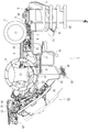
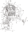
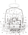
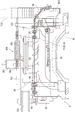
First, the outline of the herbicide unit 1 will be described with reference to Figs. 1 and 2. Fig. The rehabilitation machine 1 of the embodiment has a traveling vehicle 2 supported by a pair of right and left front wheels 3 as a traveling part and a pair of right and left rear wheels 4 in the same manner. The engine 5 is mounted on the front portion of the traveling base 2 and the power from the engine 5 is transmitted to the rear transmission case 6 to drive the front wheels 3 and the rear wheels 4 And is configured to travel forward and backward. The front axle case 7 is projected to the left and right sides of the transmission case 6 and the front wheels 3 are conductively attached to the front axle extending from the front axle case 7 to the left and right. The rear axle case 9 is fixed to the rear end side of the tubular frame 8 by projecting the tubular frame 8 behind the transmission case 6 and the rear axle case 9 is extended from the rear axle case 9 in the left- The rear wheel 4 is attached to the rear axle.
As shown in Figs. 1 and 2, a work step (body cover) 10 for boarding the operator is provided on the front side of the traveling base 2 and the upper side of the central portion. A front bonnet 11 is disposed above the front portion of the work step 10 and an engine 5 is provided inside the front bonnet 11. [ A running speed change pedal 12 is arranged on the upper side of the working step 10 on the side of the rear side of the front bonnet 11 in the actuation direction. Although the detailed description is omitted, the pancake unit 1 of the embodiment is configured to adjust the shift power output from the hydraulic CVT of the mission case 6 by driving the variable speed electric motor in accordance with the depression amount of the speed change pedal 12 have.
A steering handle 14, a running peripheral speed lever 15 and a working lever 16 are provided on a driving operation portion 13 on the rear upper surface side of the front bonnet 11. A steering seat 18 is disposed on the rear side of the front bonnet 11 in the upper surface of the work step 10 through a seat frame 17. On the left and right sides of the front bonnet 11, left and right preliminary seedlings 24 are provided with a work step 10 therebetween.
A link frame (19) is installed upright at the rear end of the traveling base (2). The seedling planting device 23 for planting the 8-row planting is connected to the link frame 19 via the parallel link mechanism 22 comprising the lower link 20 and the top link 21 so as to be able to ascend and descend. The operator is carried on the work step 10 from the elevation step 25 on the side of the work step 10 and drives the seedling type device 23 to feed the seedlings to the pavement Execute planting work (planting work). In addition, during the seedling planting operation, the seedling mat on the preliminary seedling stand 24 is occasionally supplied to the seedling planting device 23 by the operator.
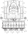
3 and 4, the seedling type feeding device 23 includes a feeding input case 26 through which power from the engine 5 is transmitted via the transmission case 6, A seedling planting mechanism 28 provided on the rear end side of each food borne transmission case 27 and a seedling plant 29 for planting eight plants, And a float 32 for a non-surface flattened surface disposed on the lower surface of each eating-and-conveying case 27. The seedling planting mechanism 28 is provided with a rotary case 31 having two food compartments 30 for one tank. Two rotary casings 31 are disposed in the food-feeding transmission case 27. The two food claws 30 cut and hold the seedlings for one week each by a single rotation of the rotary case 31 and feed the seedlings to the rice surface grounded by the float 32. [
The power transmitted from the engine 5 via the transmission case 6 is transmitted to the front wheels 3 and the rear wheels 4 as well as to the food inlet case 26 of the seedling- Lt; / RTI > In this case, the power from the transmission case 6 to the seedling type device 23 is once transmitted to a four-period transmission case (not shown) provided on the upper right side of the rear axle case 9, So that power is transmitted to the case 26. The seedling planting device 28 and the seedling stand 29 are driven by the transmitted power. Although a detailed description is omitted, a four-period transmission mechanism for switching a for-sparse period of a seedling to be fed into the four-period transmission case by, for example, a cruciform planting, a standard planting, And a PTO clutch for connecting / disconnecting the PTO clutch.
Further, the side marker 33 is provided on the left and right outside of the seedling-type seedling unit 23. [ The side marker 33 has a marker wheel 34 for line drawing and a marker arm 35 for rotatably supporting the marker wheel 34. The proximal end side of each marker arm 35 is pivotally supported on the left and right outer sides of the seedling type device 23 so as to be rotatable in the left and right direction. The side marker 33 has a working posture formed by landing a locus to be a reference in the next step on the non-magnetic surface based on the operation of the working lever 16 in the driving operation section 13, So as to be able to rotate in a non-working posture spaced apart from the surface of the rice.
(2) Support structure of the engine and surrounding structure of the engine
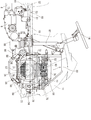
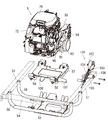
Next, the supporting structure of the engine 5 with respect to the traveling base 2 and the structure around the engine 5 will be described with reference to Figs. 3 to 12. Fig. As shown in Figs. 3 and 4, the traveling base 2 is provided with a pair of left and right base frames 50 extending back and forth. Each base frame 50 is divided into a front sub-frame 51 and a rear sub-frame 52 in two. The rear end portion of the front sub-frame 51 and the front end portion of the rear sub-frame 52 are welded and fixed to the intermediate connection frame 53, which is laterally long in the left and right direction. The front end portions of the pair of left and right front sub-frames 51 are welded and fixed to the front frame 54. The rear end side of the pair of left and right rear frames 52 is welded and fixed to the rear frame 55. [ The front frame 54, the left and right front side frames 51, and the intermediate connection frame 53 are formed in a rectangular frame shape when seen from the plane. Similarly, the intermediate connecting frame 53, the left and right rear frames 52, and the rear frame 55 are also formed in a rectangular frame shape when seen from the plane.
As shown in Figs. 5 to 7, the front portions of the left and right front sub-frames 51 are connected by two front and rear base frames 56, respectively. Each of the base frames 56 is formed in a U-shape so that the middle portion thereof is located lower than both the left and right front sub-frames 51. The left and right end portions of the base frames 56 are welded and fixed to the corresponding front sub-frames 51, respectively. The engine 5 is mounted on both of the front and rear base frames 56 via the approximately planar engine base 57 and the plurality of anti-vibration rubber members 58 as anti-vibration members. The front side base frame 56 is connected to the front frame 54 via a front relay frame 59 welded and fixed thereto. And the base frame 56 on the rear side is connected to the front portion of the mission case 6 through a rear relay bracket 60. [ The engine 5 of the embodiment is a four-stroke V-type two-cylinder gasoline engine.
4, rear portions of the left and right front sub-frames 51 are connected to the front axle case 7 protruded to the left and right sides of the transmission case 6, respectively. The left and right ends of the U-shaped frame 61, which extends obliquely downward as viewed from the side, are fixed to the center of the intermediate connecting frame 53 by welding. An intermediate portion of the U-shaped frame 61 is connected to the middle portion of the tubular frame 8 connecting the transmission case 6 and the rear axle case 9 (see FIGS. 3 and 4). In the middle portion of the rear frame 55, the upper ends of the two vertical frames 62 are welded and fixed. A middle portion of the rear axle supporting frame 63, which is laterally longer in the left and right directions, is fixedly welded to the lower ends of the right and left vertical frames 62. Both left and right ends of the rear axle supporting case 63 are connected to the rear axle case 9. A muffler 65 for reducing the exhaust sound of the engine 5 is disposed below the step support 64 protruding outwardly from the left front side frame 51.
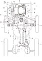
4 to 6, a power steering unit 66 is provided at a front portion of the mission case 6 disposed at the rear of the engine 5. A handle shaft (not shown) is rotatably disposed inside the handle post 67 erected on the upper surface of the power steering unit 66. A steering handle 14 is fixed to an upper end side of the handle shaft. A steering output shaft (not shown) protrudes downward on the lower side of the power steering unit 66. The steering output shaft is connected to a steering lever 68 (see Fig. 4) for steering the front wheels 6 on the left and right sides.
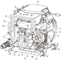
The engine 5 of the embodiment is disposed on the middle portion of the front and rear base frames 56 toward the left and right in the output shaft 70 (crankshaft). The left and right widths of the engine 5 and the engine mount 57 are smaller than the inner dimension between the left and right front subframes 51 and the lower side of the engine 5 and the engine mount 57 are located in the middle of the front and rear base frames 56 And are exposed downward from both the left and right front sub-frames 51 in a state where they are disposed on the floor. In this case, the output shaft 70 (axial line) of the engine 5 overlaps with both the left and right front sub-frames 51 when viewed from the side.
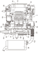
The output shaft (70) of the engine (5) protrudes outwardly from both left and right sides of the engine (5). A suction fan 71 for air cooling the engine is provided at one projecting end (the right projecting end in the embodiment) of the output shaft 70 (see Fig. 5). The suction fan (71) is configured to rotate integrally with the output shaft (70). The suction fan 71 is covered with a fan cover 72. The cooling wind introduction port 73 formed at the center of the fan cover 72 is provided with a dust-proofing network 74. The engine 5 itself is forcibly cooled by the cooling wind introduced from the cooling wind inlet 73 by the rotation of the suction fan 71. [
The engine 1 is rotated from the left and right sides of the front bonnet 11 (which may be referred to as an engine room) to the other side (left to right in the embodiment) by the rotation of the suction fan 71 (Outside air) for cooling the cooling air. In other words, a flow port 75 for allowing cooling wind to flow into and out of the front bonnet 11 is formed on the lower side of the left and right sides of the front bonnet 11. In the embodiment, a plurality of slit-shaped through-holes are formed on both right and left sides of the front bonnet 11 so as to be vertically arranged with a proper spacing therebetween. These through hole groups are formed in the flow port 75.
Therefore, when the suction fan 71 rotates, the air in the front bonnet 11 flows from right to left, the pressure in the front bonnet 11 drops, and a difference occurs in the pressure inside and outside the front bonnet 11. Then, the cooling wind is introduced from below the flow port 75 on the right side, the front side frame 51 on the right side and the work step 10, and the engine 5 is air-cooled by the introduced cooling wind. The cooling wind (air flow) circulated in the front bonnet 11 and warmed is discharged from the front bonnet 11 through the left flow port 75, the left front sub-frame 51 and the work step 10 (See FIG. 7).
On the upper surface of the engine 5, a cleaner case 76 for accommodating an air cleaner (not shown) is vertically disposed at an appropriate interval. The clearance formed between the cleaner case 76 and the engine 5 passes through right and left to constitute an upper ventilation path 77 (see FIG. 7) through which the cooling wind introduced by the rotation of the suction fan 71 can pass have. Although not shown, a communication hole for communicating the inside and the outside of the cleaner case 76 is formed in the vicinity of the suction fan 71 on the lower surface side of the cleaner case 76. The cooling air passing through the upper ventilation path 77 is introduced into the cleaner case 76 via the communication hole by the rotation of the suction fan 71. [ Further, the cleaner case 76 is connected to the intake machine of the engine 5. The cooling air filtered by the air cleaner in the cleaner case 76 is transferred to the intake system (carburetor or the like) of the engine 5. [ The cooling air is introduced into the cleaner case 76 by the rotation of the suction fan 71 so that the temperature rise in the cleaner case 76 is suppressed and cool air is supplied to the intake machine (carburetor or the like) As a result, the driving efficiency of the engine 5 can be improved.
A first oil cooler 78 for cooling engine oil is provided on the rear side of the engine 5. A second oil cooler 79 for cooling engine oil, which is opposed to the cooling air inlet 73, is disposed outside the fan cover 72. The second oil cooler 79 is connected to the first oil cooler 78 to maintain the cooling capability of the first oil cooler 78. The cooling wind introduced into the front bonnet 11 by the rotation of the suction fan 71 is jetted to the first and second oil coolers 78 and 79 so that the first and second oil coolers 78 and 79 Engine oil) is forcibly cooled. The second oil cooler 79 of the embodiment is located between the right front sub-frame 51 and the right side surface (the fan cover 72 side) of the engine 5, and the right side front sub- Respectively. In other words, the second oil cooler 79 is disposed below the front bonnet 11 covering the engine 5 from above, and is opposed to the suction fan 71.
5 to 7, in the front bonnet 11, a substantially box-shaped bonnet frame 80 surrounding the engine 5 is connected to the front frame 54 and the handle post 67 . An attachment bracket 82 is provided on the branch frame 81 welded and fixed to one side portion (right side portion in the embodiment) of the bonnet frame 80 so as to extend vertically. And a second oil cooler 79 is connected to the lower side of the attachment bracket 82 to reach the cooling air inlet 73 of the fan cover 72. The second oil cooler 79 is rotated by the rotation of the suction fan 71 so that the cooling air introduced from below the front subframe 51 and the work step 10, It is cooled first. Therefore, the cooling efficiency of the second oil cooler 79 can be improved without using the cooling fan dedicated to the second oil cooler 79, contributing to the downsizing of the second oil cooler 79. [
On the upper side of the attachment bracket 82, an electric component 83 such as a controller relating to the engine 5 is attached. The electric component 83 is mounted on the right side flow port 75 from the inside of the front bonnet 11. The cooling wind that has passed through the flow port 75 on the right side by the rotation of the suction fan 71 is sprayed on the electric component 83 and the electric component 83 is cooled. The temperature rise of the electric component 83 disposed around the engine 5 can be suppressed by the cooling wind from the flow port 75 on the right side. The adverse effect on the electric component 83 due to the heat of the engine 5 can be avoided. The inlet side of the upper ventilation path 77 between the cleaner case 76 and the engine 5 is located on the opposite side of the right flow port 75 with the electric component 83 therebetween ).
6 and 7, the outlet side of the upper air passage 77 is opened on the upper side of the other side (the left side in the embodiment) of the engine 5 opposite to the suction fan 71. As shown in Fig. A ventilation duct 84 is attached to the upper side of the left side surface of the engine 5 so as to surround the outlet side of the upper ventilation path 77 when viewed from the side. The ventilation duct 84 is located at a position higher than the left front side frame 51 and is located at the left side flow port 75 from the inside of the front bonnet 11. And the ventilation duct 84 forms an upper ventilating passage 85 of the engine 5. That is, the exhausted air that has passed through the upper ventilation path 77 and absorbed heat of the engine 5 is discharged through the ventilation duct 84 from the left flow port 75 to the front bonnet 11. The presence of the ventilation duct 84 prevents the warmed airflow from returning to the front bonnet 11 and can be smoothly discharged from the left side flow port 75 to improve the discharge efficiency of the airflow.
7, the heated air taken from the engine 5 is discharged out of the front bonnet 11 via the upper air path 85, and the left front frame 51 and the working step 10). That is, the lower side of the left front side frame 51 and the working step 10 is formed in the lower airflow path 86 of the engine 5.
An exhaust pipe 87 communicating with the exhaust system of the engine is disposed on the other side (the left side in the embodiment) of the engine 5 opposite to the suction fan 71. The exhaust pipe 87 extends between the ventilation duct 84 and the other projecting end portion (the left projecting end portion in the embodiment) of the output shaft 70, and is extended from one side (front side in the embodiment) Like shape extending in the longitudinal direction. The exhaust pipe 87 of the embodiment includes a horizontal tube portion 87a extending across the ventilation duct 84 and the output shaft 70 and a vertical tube portion 87b extending forwardly and downwardly from the output shaft 70, And a connecting pipe portion 87c extending from the lower end of the vertical pipe portion 87b toward the muffler 65. [ The base end of the horizontal tube portion 87a is connected to one of the cylinders of the engine 5. A portion of the horizontal tube portion 87a that branches from a portion near the vertical tube portion 87b is connected to the other cylinder of the engine 5. [ Therefore, the exhaust gas from both cylinders joins in front of the vertical tube portion 87b in the horizontal tube portion 87a. And the tip end side of the connecting tube portion 87c is connected to the exhaust inlet side of the muffler 65. [
A shielding cover 88 surrounding the horizontal tube portion 87a and the vertical tube portion 87b of the exhaust pipe 87 is provided on the left side surface of the engine 5. The shielding cover 88 of the embodiment includes a horizontal cover member 89 covering the horizontal tube portion 87a and a vertical cover member 90 covering the vertical tube portion 87b. The horizontal cover member 89 is made of a metal plate having an upper face plate, a rear face plate and a left face plate. Further, the vertical cover member 90 is made of a metal plate having a top plate, a bottom plate, left and right face plates, and a front plate. That is, the horizontal cover member 89 and the vertical cover member 90 are formed in a substantially box shape with the discharge fan 91 side provided at the other projecting end (the left projecting end in the embodiment) of the output shaft 70 opened have. The horizontal cover member 89 and the vertical cover member 90 are arranged in a substantially L shape when viewed from the side in terms of surrounding the horizontal pipe portion 87a and the vertical pipe portion 87b of the exhaust pipe 87. [ The shielding cover 88 encloses the horizontal pipe portion 87a and the vertical pipe portion 87b of the exhaust pipe 87 to prevent the heat generated from the exhaust pipe 87 from being diffused in the front bonnet 11. [ Needless to say, the ventilation duct 84 and the shielding cover 88 of the embodiment are located between the left front sub-frame 51 and the left side surface of the engine 5 and are housed in the front bonnet 11 (See FIG. 7).
6 and 9, the inner side of the shield cover 88 (the inner side divided by the horizontal cover body 89 and the vertical cover body 90) of the left side of the engine 5 is provided with the other side of the output shaft 70 (In the embodiment, the left projecting end) protrudes. At the left projecting end of the output shaft 70, a discharge fan 91 is provided separately from the suction fan 71. The discharge fan 91 is configured to rotate integrally with the output shaft 70, like the suction fan 71. The surrounding exhaust air is introduced by the rotation of the exhaust fan 91 and is discharged mainly from the lower exhaust path 86 (downward of the left front frame 51 and the working step 10) to the front bonnet 11 . Therefore, the cooling fan is sprayed to the engine 5 by the rotation of the suction fan 71 on the right side of the engine 5 to forcibly cool the engine 5, So that the cooling wind introduction effect of the suction fan 71 and the wind exhaust effect of the exhaust fan 91 are reduced as well as the effect of cooling air introduction of the exhaust fan 91. [ It is possible to remarkably improve the cooling efficiency of the heat exchanger 5.
Since the horizontal cover member 89 and the vertical cover member 90 are formed in a substantially box shape with the discharge fan 91 side opened as described above, heat generated from the discharge pipe 87 is transferred to the front bonnet 11 And is actively discharged out of the front bonnet 11 via the lower air discharge path 86 by the rotation of the discharge fan 91. [ Therefore, the heat environment on the left side of the engine 5 having the exhaust pipe 87, and further, the heat environment in the front bonnet 11 can be improved.
A plurality of output pulleys 92 and 93 for transmitting torque as well as a discharge fan 91 are provided in the left projecting end of the output shaft 70 as shown in Figs. 6, 8, 9 and 11 2) are installed. The output pulleys 92 and 93 are configured to rotate together with the discharge fan 91 by the rotation of the output shaft 70. Each of the output pulleys 92 and 93 is disposed in the axial direction of the output shaft 70 with the discharge fan 91 interposed therebetween. The output pulley 92 closer to the engine 5 is a first output pulley 92 for transmitting rotational power to a generator 94 (to be described later in detail) Is a second output pulley 93 for transmitting rotational force to a mission input shaft 97 (details will be described later) protruding leftward outward from the transmission case 6.
Here, the generator 94 is disposed on the opposite side (rear side in the embodiment) of the vertical pipe portion 87b of the exhaust pipe 87 with the left projecting end portion of the output shaft 70 interposed therebetween. The generator 94 is attached to a fixed bracket 95 bolted to the left rear side of the left side projecting end of the output shaft 70 in the left side of the engine 5 and below the transverse cover body 89. Although not shown, the left side of the engine 5 and the generator 94 are appropriately spaced from each other. An auxiliary machine input pulley 94a is provided on the side of the generator 94 opposed to the left side of the engine 5. The transmission belt 96 is wound around the first output pulley 92 on the output shaft 70 side and the auxiliary machine input pulley 94a on the generator 94 side. A rotational force is transmitted from the engine 5 to the generator 94 via the pulley 92 and the belt 96 electric power system so that the generator 94 is generated. The generator 94 is attached to the left side surface of the engine 5 through the fixing bracket 95 and thus included in the same vibration system as the engine 5. [ Therefore, the load applied to the generator 94 itself can be reduced, and the risk of deformation or breakage of the generator 94 can be suppressed.
On the other hand, a mission input pulley 98 is provided on the mission input shaft 97 protruding leftward from the mission case 6. The transmission belt 99 is wound around the second output pulley 93 on the output shaft 70 side and the mission input pulley 98 on the transmission case 6 side. The rotational force is transmitted from the engine 5 to the mission case 6 through the pulleys 93 and 98 and the belt 99 electrical system. A mission cooling fan 100 for air cooling of the mission case 6 is provided on the left side of the mission output shaft 97 on the left side of the mission input pulley 98. [ The mission cooling fan 100 is configured to rotate together with the mission input pulley 98 by the rotational force transmitted through the pulleys 93 and 98 and the belt 99 electrical system.
6 and 9, a discharge fan 91, first and second output pulleys 92 and 93, a generator 94, and a transmission / discharge valve 93 are disposed inside the shielding cover 88 on the left side of the engine 5, Belts 96 and 99 are disposed. The pulleys 92 and 93 and the belts 96 and 99 are disposed compactly on the inside of the shielding cover 88 on the left side of the engine 5 while the exhaust fan 91 The heat around the left side surface of the engine 5 can be smoothly discharged via the lower air discharge path 86. [ The pulleys 92 and 93 and the belts 96 and 99 can be cooled by injecting the air to the electric power generators 94 and thus the pulleys 92 and 93 and the belts 96 and 99, ) Can be suppressed, and the durability of these can be improved.
11, the outer diameter of the discharge fan 91 is larger than the diameter of each of the output pulleys 92 and 93. As shown in Fig. Therefore, there is little fear that the presence of the output pulleys 92 and 93 will interfere with the discharge of the exhaust air via the lower air discharge path 86 by the rotation of the discharge fan 91, It is possible to maintain the discharge efficiency of the exhaust air well. Further, the output pulleys 92 and 93 are formed to have a smaller diameter as they are closer to the engine 5. Therefore, when the heat on the left side of the engine 5 is taken off by the rotation of the discharge fan 91, the influence of the first output pulley 92 closer to the engine 5 being present can be reduced. The output pulleys 92 and 93 and the discharge fan 91 are compactly mounted on the left projecting end portion of the output shaft 70 while suppressing thermal deterioration of the pulleys 92 and 93 and the belts 96 and 99 And it is possible to suppress the enlargement of the width of the front bonnet 11 covering the engine 5 and thus covering it.
A tension applying member 101 for tensioning the transmission belt 99 is provided between the second output pulley 93 on the output shaft 70 side and the transmission output pulley 98 as shown in Figs. 3, 6 and 11 Respectively. The tension imparting member 101 is provided with a tension pulley 102 that contacts the transmission belt 99 from below. The tension pulley 102 is pivotally supported on the free end side of a tension arm 103 which is vertically rotatably connected to the left side of the engine mount 57. The tension arm 103 is tensioned in the upward rotating direction by the biasing spring 104 so that the tension pulley 102 always presses against the transmission belt 99 from below. The biasing spring 104 is mounted between the swinging arm 106 erected on the boss 105 on the base end side of the tension arm 103 and the support plate 107 protruded on the left side of the engine mount 57 have.
Since the tension imparting member 101 is provided in the engine mount 57 on which the engine 5 is mounted and the tension imparting member 101 is included in the same vibration system as the engine 5, The load applied to itself can be reduced. As a result, it is possible to suppress the risk of deformation or breakage of the tension imparting member (101). In addition, there is an advantage that the vibration of the tension imparting member 101 follows the vibration of the engine 5, and the transmission belt 99 can be easily held in a proper tension state. In the embodiment, not only the tension imparting member 101 but also the generator 94 are disposed between the second output pulley 93 and the mission output pulley 98 together with the engine 5 and the transmission case 6 in the front- So that space between the engine 5 and the mission case 6 is effectively utilized.
The engine 5 of the embodiment is bolted to the engine mount 57 supported by the front and rear base frames 56 via a plurality of anti-vibration rubber members 58. As shown in Figs. 8, 9 and 12, an exhaust hole 108 is formed in the engine mount 57 at the bottom of the engine 5 in the up-and-down direction. And the rib groove 109 formed in the bottom surface of the engine 5 is placed in the exhaust hole 108 of the engine mount 57. [ In this case, the engine 5 is disposed on the engine mount 57 so as to flow the cooling air from the exhaust hole 108 toward the exhaust fan 91 on the left side of the engine from the exhaust hole 108 (to the right) have. In other words, a part of the exhaust hole 108 is opened vertically without covering the entire exhaust hole 108 of the engine mount 57 with the bottom surface of the engine 5. The first output pulley 92 and the transmission belt 96 on the left side of the engine 5 are visible in a part of the exhaust hole 108 when the exhaust hole 108 is viewed from the lower side of the engine mount 57 do.
When the exhaust holes 108 on the bottom surface of the engine 5 are formed in the engine mount 57 as described above, the cooling air introduced by the rotation of the suction fan 71 is guided to the bottom surface of the engine 5 It is possible to positively cool the engine oil in the engine 5, thereby suppressing an excessive increase in the engine oil temperature. The cooling efficiency of the first and second oil coolers 78 and 79 as well as the cooling of the engine oil can be effectively performed and the heat balance of the engine 5 can be well maintained. Since the engine 5 is disposed on the engine mount 57 so as to be out of the exhaust hole 108 so that the cooling air flows from the exhaust hole 108 toward the exhaust fan 91, The cooling wind can be transferred from the bottom surface side of the engine 5 toward the left side surface via the exhaust hole 108 by the rotation. Therefore, the temperature of the air itself can be lowered by mixing the cooling wind of relatively low temperature around the left side surface of the engine 5, and the thermal environment on the left side of the engine 5 can be greatly improved.
(3) Theorem
According to the above embodiment, the engine 5 mounted on the traveling base 2 and the transmission case 4 for transmitting the power of the engine 5 to the traveling sections 3 and 4 of the traveling base 2 And a seedling feeding device 23 mounted on the traveling base 2 and having a suction fan 71 for air cooling on one side of the engine 5, (87) communicating with the exhaust system of the engine (5) is provided on the other side of the engine (5) opposite to the suction fan (71) with an output shaft (70) protruding from the other side interposed therebetween. 87b) and the generator 94 to the both sides of the output shaft 70, the exhaust pipe 87 (87b) and the generator 94 are extended to the exhaust pipe 87b (87 (87b)) and the upper surface of the exhaust pipe (87 (87b)) on the other side of the engine (5) while suppressing an adverse effect on the generator (94) The generator 94 can be compactly arranged.
A transmission belt 99 wound around a mission input pulley 98 fixed to a transmission input shaft 97 of the transmission case 6 and an output pulley 93 fixed to the output shaft 70, And the tension applying member 101 and the generator 94 are positioned between the output pulley 93 and the mission input pulley 98 The space between the engine 5 and the mission case 6 can be effectively used to reduce the size of the arrangement of the pulleys 93 and 98 and the belt 99 to the transmission case 6 have.
The engine 5 is mounted on the engine base 57 attached to the traveling base 2 through the anti-vibration member 58, and the tension imparting member 101 is attached to the engine base 57 And the generator 94 is attached to the fixing bracket 95 fastened to the other side of the engine 5 so that the tension imparting member 101 and the generator 94 are connected to the engine 5 And the like. Therefore, the load applied to the tension imparting member 101 and the generator 94 itself can be reduced, and the risk of deformation or breakage of the tension imparting member 101 and the generator 94 can be suppressed.
According to the above embodiment, the engine 5 mounted on the traveling base 2 and the transmission case 4 for transmitting the power of the engine 5 to the traveling sections 3 and 4 of the traveling base 2 And a seedling feeding device 23 mounted on the traveling base 2 and having a suction fan 71 for air cooling on one side of the engine 5, And the engine 5 is disposed between the pair of left and right base frames 50 constituting the traveling base 2 so as to protrude below the base frames 50. The engine 5 A ventilation duct 84 for passing the cooling wind from the suction fan 71 is disposed on the other side of the opposite side of the suction fan 71 from the gas frame 50. The ventilation duct 84, And the lower portion of the gas frame 50 on the other side of the engine 5 It is possible to suppress the spread of the warmed air generated in the engine room due to the heat of the engine 5 due to the presence of the ventilation duct 84 . Further, it is possible to prevent the exhaust air from staying in the engine room and to smoothly discharge the exhaust air from the upper air path 85, thereby improving the discharge efficiency of the exhaust air. In addition, the exhaust path of the engine 5 can be divided into two parts, that is, the upper air path 85 and the lower air path 86, so that the air can be efficiently discharged outside the engine room, The efficiency can be maintained in a good state.
A cleaner case 76 for accommodating the air cleaner is disposed on the upper surface of the engine 5 at appropriate intervals in the vertical direction and an upper ventilation path (not shown) between the cleaner case 76 and the engine 5 77 can communicate with the ventilation duct 84 so that cooling air can be introduced around the upper surface of the engine 5 by the rotation of the suction fan 71 to cool the periphery of the upper surface of the engine 5 . Further, it is possible to take out the heat around the upper surface of the engine 5 and discharge the heated air smoothly through the ventilation duct 84. Therefore, the cooling efficiency of the engine 5 is enhanced.
The output shaft 70 protruding from the other side of the engine 5 overlaps the base frame 50 on the other side of the engine 5 when viewed from the side, An exhaust pipe 87 communicating with the exhaust system of the engine 100 is formed in an L shape extending in the longitudinal direction from one side across the output shaft 70 after crossing between the ventilation duct 84 and the output shaft 70 Since the shield cover 88 surrounding the exhaust pipe 87 is provided on the other side surface of the engine 5, the heat generated from the exhaust pipe 87 due to the presence of the shield cover 88 Can be suppressed from being diffused in the engine room.
According to the above embodiment, the engine 5 mounted on the traveling base 2 and the transmission case 4 for transmitting the power of the engine 5 to the traveling sections 3 and 4 of the traveling base 2 And a seedling feeding device 23 mounted on the traveling base 2 and having a suction fan 71 for air cooling on one side of the engine 5, And the exhaust fan 91 is provided on the other side of the engine 5 opposite to the suction fan 71 so as to be separate from the suction fan 71. Therefore, Not only the engine 5 is forcedly cooled by spraying the cooling air to the engine 5 by the suction fan 71 but also by the rotation of the discharge fan 91 on the other side of the engine 5 The heat of the engine 5 is taken away and the heated air is discharged from the engine room. Accordingly, the cooling effect of the suction fan 71 and the exhaust fan 91 can be improved, and the cooling efficiency of the engine 5 can be improved remarkably.
The output shaft 70 of the engine 5 is provided with output pulleys 92 and 93 for transmitting rotational force together with the discharge fan 91. The discharge fan 91 and the output pulleys 92, 93 are configured to rotate together by the rotation of the output shaft 70 so that wind is blown to the output pulleys 92, 93 using the rotation of the discharge fan 91, 93 can be cooled. Therefore, thermal degradation of the output pulleys 92, 93 can be suppressed while compactly arranging the discharge fan 91 and the output pulleys 92, 93, thereby improving their durability. The disposition of the discharge fan 91 and the output pulleys 92 and 93 can be made compact so that expansion of the width of the engine 5 and further the width of the engine room can be suppressed.
Since the outer diameter of the discharge fan 91 is larger than that of the output pulleys 92 and 93, when the discharge fan 91 discharges the air by the rotation of the discharge fan 91, the output pulleys 92 and 93 Is less likely to be interfered with, and the discharge efficiency of the exhaust air caused by the rotation of the discharge fan 91 can be satisfactorily maintained.
Since the plurality of output pulleys 92 and 93 are formed to have a smaller diameter as the engine 5 approaches the engine 5, It is possible to reduce the influence of the presence of the output pulley 92 closer to the engine 5 when the heat on the other side of the engine 5 is taken off by rotation.
According to the above embodiment, the engine 5 mounted on the traveling base 2 and the transmission case 4 for transmitting the power of the engine 5 to the traveling sections 3 and 4 of the traveling base 2 And a seedling feeding device 23 mounted on the traveling base 2 and having a suction fan 71 for air cooling on one side of the engine 5, The engine 5 is mounted on the engine base 57 attached to the traveling base 2 through the anti-vibration member 58, and the engine base 57 is provided with The cooling air introduced by the rotation of the suction fan 71 can be sprayed on the bottom surface of the engine 5 because the exhaust hole 108 is formed. Therefore, the engine oil in the engine 5 is actively cooled to suppress the excessive increase of the engine oil temperature, so that the heat balance of the engine 5 can be well maintained.
In addition, a discharge fan is provided separately from the suction fan on the other side of the engine 5 opposite to the suction fan 71, so that the cooling air flows from the discharge hole to the discharge fan. The cooling air is blown from the bottom surface side of the engine 5 to the other side surface side via the exhaust hole 108 by the rotation of the exhaust fan 91 because the engine is disposed shifted from the exhaust hole on the engine 5, As shown in Fig. Therefore, it is possible to lower the temperature of the wind itself by mixing the cooling wind of relatively low temperature to the wind around the other side of the engine 5, so that the thermal environment on the other side of the engine 5 can be greatly improved.
The engine 5 and the engine mount 57 are disposed so as to protrude downward from both the base frames 50 between a pair of left and right base frames 50 constituting the traveling base 2 Therefore, it is possible to smoothly introduce the cooling air from the bottom surface side of the engine 5.
According to the above embodiment, the engine 5 mounted on the traveling base 2 and the transmission case 4 for transmitting the power of the engine 5 to the traveling sections 3 and 4 of the traveling base 2 And a seedling feeding device 23 mounted on the traveling base 2 and having a suction fan 71 for air cooling on one side of the engine 5, And the engine 5 is disposed so as to protrude below the both base frames 50 between a pair of left and right base frames 50 constituting the traveling base 2, The oil cooler 79 is disposed below the front bonnet 11 covering from above so as to face the suction fan 71 so that the oil cooler 79 is rotated by the rotation of the suction fan 71, Is cooled before the engine (5) by the cooling wind introduced from below the base frame (50). Therefore, the cooling efficiency of the oil cooler 79 can be improved without using a cooling fan dedicated to the oil cooler 79. Thereby contributing to the downsizing of the oil cooler 79.
An electric component 83 disposed above the oil cooler 79 is placed in a flow port 75 formed on the lower side of the front bonnet 11 so as to surround the engine 5, The oil cooler 79 and the electric component 83 are supported by the bonnet frame 80 provided in the housing 11 so that the cooling wind which has passed through the flow port 75 by the rotation of the suction fan 71 And the electric component 83 is cooled by being sprayed onto the electric component 83. The temperature rise of the electric component 83 disposed around the engine 5 can be suppressed by the cooling wind from the flow port 75. [ The adverse effect on the electric component 83 due to the heat of the engine 5 can be avoided. The bonnet frame 80 can be used to simplify the supporting structure of the oil cooler 79 and the electric component 83.
According to the above embodiment, the engine 5 mounted on the traveling base 2 and the transmission case 4 for transmitting the power of the engine 5 to the traveling sections 3 and 4 of the traveling base 2 And a seedling feeding device 23 mounted on the traveling base 2 and having a suction fan 71 for air cooling on one side of the engine 5, Wherein the engine 5 is mounted on the traveling base 2 in the left-right direction and the other side of the engine 5 opposite to the suction fan 71 is connected to the suction fan 71 Since the shielding cover 88 surrounding the exhausting fan 91 is provided on the other side of the engine 5, the suction fan 71 The cooling effect of the engine 5 and the effect of ventilation of the exhaust fan 91 can be remarkably improved. In addition, the shielding cover 88 The heat in the vicinity of the left side surface of the engine 5 can be prevented from diffusing in the engine room.
The output shaft 70 of the engine 5 is provided with output pulleys 92 and 93 for transmitting rotational force together with the exhaust fan 91. The output shaft 70 of the engine 5 is connected to the shield cover 93 and the belts 96, 99 are disposed on the inside of the pulleys 92, 93 and the discharge fan 91, the generator 94, the pulleys 92, 93 and the belts 96, And the heat around the left side surface of the engine 5 can be smoothly discharged by rotating the discharge fan 91 while arranging the electric motor or the generator 94 compactly. Since the discharge fan 91 can rotate the pulleys 92 and 93 and the belts 96 and 99 and the generator 94 by blowing an air stream to the pulleys 92 and 93 And the thermal degradation of the belts 96 and 99 and the generator 94 and the durability of the belts 96 and 99 can be improved.
(4) Other
The present invention may be embodied in various forms without being limited to the above-described embodiments. The configuration of each unit is not limited to the illustrated embodiment, and various modifications can be made without departing from the spirit of the present invention.