KR20140137461A - Hemodialysis systems and methods - Google Patents
Hemodialysis systems and methods Download PDFInfo
- Publication number
- KR20140137461A KR20140137461A KR1020147030728A KR20147030728A KR20140137461A KR 20140137461 A KR20140137461 A KR 20140137461A KR 1020147030728 A KR1020147030728 A KR 1020147030728A KR 20147030728 A KR20147030728 A KR 20147030728A KR 20140137461 A KR20140137461 A KR 20140137461A
- Authority
- KR
- South Korea
- Prior art keywords
- fluid
- pump
- cassette
- dialysis
- blood
- Prior art date
Links
- 238000001631 haemodialysis Methods 0.000 title claims abstract description 96
- 230000000322 hemodialysis Effects 0.000 title claims abstract description 96
- 238000000034 method Methods 0.000 title abstract description 115
- 239000012530 fluid Substances 0.000 abstract description 443
- 239000000385 dialysis solution Substances 0.000 abstract description 284
- 230000017531 blood circulation Effects 0.000 abstract description 155
- 239000008280 blood Substances 0.000 abstract description 147
- 210000004369 blood Anatomy 0.000 abstract description 147
- 238000000502 dialysis Methods 0.000 abstract description 103
- 238000002156 mixing Methods 0.000 abstract description 94
- 238000004891 communication Methods 0.000 abstract description 33
- XLYOFNOQVPJJNP-UHFFFAOYSA-N water Substances O XLYOFNOQVPJJNP-UHFFFAOYSA-N 0.000 description 102
- 239000007788 liquid Substances 0.000 description 92
- 238000005086 pumping Methods 0.000 description 83
- 238000011282 treatment Methods 0.000 description 51
- 239000007789 gas Substances 0.000 description 47
- 239000003146 anticoagulant agent Substances 0.000 description 46
- 229940127219 anticoagulant drug Drugs 0.000 description 46
- 239000000463 material Substances 0.000 description 42
- 239000000523 sample Substances 0.000 description 36
- 239000000243 solution Substances 0.000 description 31
- 238000005259 measurement Methods 0.000 description 28
- UIIMBOGNXHQVGW-UHFFFAOYSA-M Sodium bicarbonate Chemical compound [Na+].OC([O-])=O UIIMBOGNXHQVGW-UHFFFAOYSA-M 0.000 description 26
- BVKZGUZCCUSVTD-UHFFFAOYSA-M Bicarbonate Chemical compound OC([O-])=O BVKZGUZCCUSVTD-UHFFFAOYSA-M 0.000 description 25
- 239000002253 acid Substances 0.000 description 24
- FAPWRFPIFSIZLT-UHFFFAOYSA-M Sodium chloride Chemical compound [Na+].[Cl-] FAPWRFPIFSIZLT-UHFFFAOYSA-M 0.000 description 22
- 238000004659 sterilization and disinfection Methods 0.000 description 22
- 230000007246 mechanism Effects 0.000 description 20
- 239000012528 membrane Substances 0.000 description 20
- 230000001954 sterilising effect Effects 0.000 description 19
- 238000010586 diagram Methods 0.000 description 17
- 230000000670 limiting effect Effects 0.000 description 17
- 230000008569 process Effects 0.000 description 16
- 238000011049 filling Methods 0.000 description 14
- 239000002699 waste material Substances 0.000 description 14
- 230000037452 priming Effects 0.000 description 13
- 235000017557 sodium bicarbonate Nutrition 0.000 description 13
- 229910000030 sodium bicarbonate Inorganic materials 0.000 description 13
- 230000008901 benefit Effects 0.000 description 11
- 230000006870 function Effects 0.000 description 11
- 239000011780 sodium chloride Substances 0.000 description 11
- 230000000875 corresponding effect Effects 0.000 description 10
- 239000000203 mixture Substances 0.000 description 10
- 239000000356 contaminant Substances 0.000 description 9
- 230000001276 controlling effect Effects 0.000 description 9
- 238000009413 insulation Methods 0.000 description 9
- 239000004033 plastic Substances 0.000 description 9
- 229920003023 plastic Polymers 0.000 description 9
- 238000002560 therapeutic procedure Methods 0.000 description 9
- 238000012546 transfer Methods 0.000 description 9
- 238000009530 blood pressure measurement Methods 0.000 description 8
- 238000012360 testing method Methods 0.000 description 8
- 238000003466 welding Methods 0.000 description 8
- 238000009529 body temperature measurement Methods 0.000 description 7
- 238000001914 filtration Methods 0.000 description 7
- 238000003825 pressing Methods 0.000 description 7
- 230000008859 change Effects 0.000 description 6
- DDRJAANPRJIHGJ-UHFFFAOYSA-N creatinine Chemical compound CN1CC(=O)NC1=N DDRJAANPRJIHGJ-UHFFFAOYSA-N 0.000 description 6
- 230000009977 dual effect Effects 0.000 description 6
- 238000010438 heat treatment Methods 0.000 description 6
- 244000052769 pathogen Species 0.000 description 6
- 239000002994 raw material Substances 0.000 description 6
- 239000010935 stainless steel Substances 0.000 description 6
- 229910001220 stainless steel Inorganic materials 0.000 description 6
- 210000001124 body fluid Anatomy 0.000 description 5
- 150000002500 ions Chemical class 0.000 description 5
- 230000033001 locomotion Effects 0.000 description 5
- 238000002360 preparation method Methods 0.000 description 5
- 239000000126 substance Substances 0.000 description 5
- XSQUKJJJFZCRTK-UHFFFAOYSA-N Urea Chemical compound NC(N)=O XSQUKJJJFZCRTK-UHFFFAOYSA-N 0.000 description 4
- QTBSBXVTEAMEQO-UHFFFAOYSA-N acetic acid Substances CC(O)=O QTBSBXVTEAMEQO-UHFFFAOYSA-N 0.000 description 4
- 239000010839 body fluid Substances 0.000 description 4
- 230000036760 body temperature Effects 0.000 description 4
- 239000004202 carbamide Substances 0.000 description 4
- 230000002596 correlated effect Effects 0.000 description 4
- 229920001971 elastomer Polymers 0.000 description 4
- 238000007373 indentation Methods 0.000 description 4
- 230000010354 integration Effects 0.000 description 4
- 238000004519 manufacturing process Methods 0.000 description 4
- BASFCYQUMIYNBI-UHFFFAOYSA-N platinum Chemical compound [Pt] BASFCYQUMIYNBI-UHFFFAOYSA-N 0.000 description 4
- 239000002510 pyrogen Substances 0.000 description 4
- 230000003068 static effect Effects 0.000 description 4
- 238000011144 upstream manufacturing Methods 0.000 description 4
- IJGRMHOSHXDMSA-UHFFFAOYSA-N Atomic nitrogen Chemical compound N#N IJGRMHOSHXDMSA-UHFFFAOYSA-N 0.000 description 3
- -1 CaCl Chemical compound 0.000 description 3
- OKTJSMMVPCPJKN-UHFFFAOYSA-N Carbon Chemical compound [C] OKTJSMMVPCPJKN-UHFFFAOYSA-N 0.000 description 3
- RTAQQCXQSZGOHL-UHFFFAOYSA-N Titanium Chemical compound [Ti] RTAQQCXQSZGOHL-UHFFFAOYSA-N 0.000 description 3
- 230000009471 action Effects 0.000 description 3
- 238000013459 approach Methods 0.000 description 3
- 230000000295 complement effect Effects 0.000 description 3
- 238000005314 correlation function Methods 0.000 description 3
- 229940109239 creatinine Drugs 0.000 description 3
- 238000013461 design Methods 0.000 description 3
- 238000001514 detection method Methods 0.000 description 3
- 238000006073 displacement reaction Methods 0.000 description 3
- 239000010439 graphite Substances 0.000 description 3
- 229910002804 graphite Inorganic materials 0.000 description 3
- 230000005484 gravity Effects 0.000 description 3
- 238000000338 in vitro Methods 0.000 description 3
- 208000015181 infectious disease Diseases 0.000 description 3
- 230000002458 infectious effect Effects 0.000 description 3
- 229910052751 metal Inorganic materials 0.000 description 3
- 239000002184 metal Substances 0.000 description 3
- 230000003287 optical effect Effects 0.000 description 3
- 230000036961 partial effect Effects 0.000 description 3
- 230000037361 pathway Effects 0.000 description 3
- 239000000047 product Substances 0.000 description 3
- 230000003134 recirculating effect Effects 0.000 description 3
- 230000000717 retained effect Effects 0.000 description 3
- 229920006395 saturated elastomer Polymers 0.000 description 3
- 238000007789 sealing Methods 0.000 description 3
- 230000001360 synchronised effect Effects 0.000 description 3
- 239000010936 titanium Substances 0.000 description 3
- 229910052719 titanium Inorganic materials 0.000 description 3
- 241001325256 Ellisia nyctelea Species 0.000 description 2
- HTTJABKRGRZYRN-UHFFFAOYSA-N Heparin Chemical compound OC1C(NC(=O)C)C(O)OC(COS(O)(=O)=O)C1OC1C(OS(O)(=O)=O)C(O)C(OC2C(C(OS(O)(=O)=O)C(OC3C(C(O)C(O)C(O3)C(O)=O)OS(O)(=O)=O)C(CO)O2)NS(O)(=O)=O)C(C(O)=O)O1 HTTJABKRGRZYRN-UHFFFAOYSA-N 0.000 description 2
- 241000282414 Homo sapiens Species 0.000 description 2
- 241000269799 Perca fluviatilis Species 0.000 description 2
- ZLMJMSJWJFRBEC-UHFFFAOYSA-N Potassium Chemical compound [K] ZLMJMSJWJFRBEC-UHFFFAOYSA-N 0.000 description 2
- UIIMBOGNXHQVGW-DEQYMQKBSA-M Sodium bicarbonate-14C Chemical compound [Na+].O[14C]([O-])=O UIIMBOGNXHQVGW-DEQYMQKBSA-M 0.000 description 2
- 208000007536 Thrombosis Diseases 0.000 description 2
- 238000009825 accumulation Methods 0.000 description 2
- 230000002378 acidificating effect Effects 0.000 description 2
- 230000005540 biological transmission Effects 0.000 description 2
- 230000000903 blocking effect Effects 0.000 description 2
- 230000004087 circulation Effects 0.000 description 2
- 239000012141 concentrate Substances 0.000 description 2
- 238000005260 corrosion Methods 0.000 description 2
- 230000007797 corrosion Effects 0.000 description 2
- 239000000806 elastomer Substances 0.000 description 2
- 230000036541 health Effects 0.000 description 2
- 229960002897 heparin Drugs 0.000 description 2
- 229920000669 heparin Polymers 0.000 description 2
- 239000004615 ingredient Substances 0.000 description 2
- 238000011016 integrity testing Methods 0.000 description 2
- 238000002955 isolation Methods 0.000 description 2
- 238000012423 maintenance Methods 0.000 description 2
- 230000014759 maintenance of location Effects 0.000 description 2
- 239000013642 negative control Substances 0.000 description 2
- 239000003921 oil Substances 0.000 description 2
- 229910052697 platinum Inorganic materials 0.000 description 2
- 229920002492 poly(sulfone) Polymers 0.000 description 2
- 229910052700 potassium Inorganic materials 0.000 description 2
- 239000011591 potassium Substances 0.000 description 2
- 239000002243 precursor Substances 0.000 description 2
- 238000010926 purge Methods 0.000 description 2
- 230000005855 radiation Effects 0.000 description 2
- 230000002829 reductive effect Effects 0.000 description 2
- 230000004044 response Effects 0.000 description 2
- 238000001223 reverse osmosis Methods 0.000 description 2
- 239000005060 rubber Substances 0.000 description 2
- 238000005070 sampling Methods 0.000 description 2
- 229910052710 silicon Inorganic materials 0.000 description 2
- 239000010703 silicon Substances 0.000 description 2
- 239000007787 solid Substances 0.000 description 2
- 239000011343 solid material Substances 0.000 description 2
- 239000000758 substrate Substances 0.000 description 2
- CCEKAJIANROZEO-UHFFFAOYSA-N sulfluramid Chemical group CCNS(=O)(=O)C(F)(F)C(F)(F)C(F)(F)C(F)(F)C(F)(F)C(F)(F)C(F)(F)C(F)(F)F CCEKAJIANROZEO-UHFFFAOYSA-N 0.000 description 2
- 241000272525 Anas platyrhynchos Species 0.000 description 1
- OYPRJOBELJOOCE-UHFFFAOYSA-N Calcium Chemical compound [Ca] OYPRJOBELJOOCE-UHFFFAOYSA-N 0.000 description 1
- 241000282472 Canis lupus familiaris Species 0.000 description 1
- BVKZGUZCCUSVTD-UHFFFAOYSA-L Carbonate Chemical compound [O-]C([O-])=O BVKZGUZCCUSVTD-UHFFFAOYSA-L 0.000 description 1
- 241000282693 Cercopithecidae Species 0.000 description 1
- 229920002943 EPDM rubber Polymers 0.000 description 1
- 239000004593 Epoxy Substances 0.000 description 1
- JOYRKODLDBILNP-UHFFFAOYSA-N Ethyl urethane Chemical compound CCOC(N)=O JOYRKODLDBILNP-UHFFFAOYSA-N 0.000 description 1
- 241000282326 Felis catus Species 0.000 description 1
- WQZGKKKJIJFFOK-GASJEMHNSA-N Glucose Natural products OC[C@H]1OC(O)[C@H](O)[C@@H](O)[C@@H]1O WQZGKKKJIJFFOK-GASJEMHNSA-N 0.000 description 1
- 101000926140 Homo sapiens Gem-associated protein 2 Proteins 0.000 description 1
- 101000716750 Homo sapiens Protein SCAF11 Proteins 0.000 description 1
- 101000723833 Homo sapiens Zinc finger E-box-binding homeobox 2 Proteins 0.000 description 1
- 229910019142 PO4 Inorganic materials 0.000 description 1
- 239000004952 Polyamide Substances 0.000 description 1
- 102100020876 Protein SCAF11 Human genes 0.000 description 1
- 239000003929 acidic solution Substances 0.000 description 1
- 238000004026 adhesive bonding Methods 0.000 description 1
- 239000003570 air Substances 0.000 description 1
- 230000010100 anticoagulation Effects 0.000 description 1
- 239000007864 aqueous solution Substances 0.000 description 1
- 102000015736 beta 2-Microglobulin Human genes 0.000 description 1
- 108010081355 beta 2-Microglobulin Proteins 0.000 description 1
- WQZGKKKJIJFFOK-VFUOTHLCSA-N beta-D-glucose Chemical compound OC[C@H]1O[C@@H](O)[C@H](O)[C@@H](O)[C@@H]1O WQZGKKKJIJFFOK-VFUOTHLCSA-N 0.000 description 1
- 239000013060 biological fluid Substances 0.000 description 1
- 230000036772 blood pressure Effects 0.000 description 1
- 230000003139 buffering effect Effects 0.000 description 1
- 239000011575 calcium Substances 0.000 description 1
- 229910052791 calcium Inorganic materials 0.000 description 1
- 230000000747 cardiac effect Effects 0.000 description 1
- 239000003518 caustics Substances 0.000 description 1
- 239000001913 cellulose Substances 0.000 description 1
- 229920002678 cellulose Polymers 0.000 description 1
- 238000006243 chemical reaction Methods 0.000 description 1
- 150000001875 compounds Chemical class 0.000 description 1
- 238000000748 compression moulding Methods 0.000 description 1
- 238000010276 construction Methods 0.000 description 1
- 230000008602 contraction Effects 0.000 description 1
- 238000007485 conventional hemodialysis Methods 0.000 description 1
- 238000001816 cooling Methods 0.000 description 1
- 238000012937 correction Methods 0.000 description 1
- 230000001351 cycling effect Effects 0.000 description 1
- 238000013016 damping Methods 0.000 description 1
- 230000007547 defect Effects 0.000 description 1
- 230000003111 delayed effect Effects 0.000 description 1
- 230000002939 deleterious effect Effects 0.000 description 1
- 230000000994 depressogenic effect Effects 0.000 description 1
- 238000003745 diagnosis Methods 0.000 description 1
- 238000009826 distribution Methods 0.000 description 1
- 239000003814 drug Substances 0.000 description 1
- 230000000694 effects Effects 0.000 description 1
- 239000000839 emulsion Substances 0.000 description 1
- 230000007613 environmental effect Effects 0.000 description 1
- 239000000835 fiber Substances 0.000 description 1
- 239000012467 final product Substances 0.000 description 1
- 229920002457 flexible plastic Polymers 0.000 description 1
- 239000006260 foam Substances 0.000 description 1
- 239000008103 glucose Substances 0.000 description 1
- 239000008187 granular material Substances 0.000 description 1
- 238000002615 hemofiltration Methods 0.000 description 1
- 230000002209 hydrophobic effect Effects 0.000 description 1
- 230000002706 hydrostatic effect Effects 0.000 description 1
- 238000001802 infusion Methods 0.000 description 1
- 230000000977 initiatory effect Effects 0.000 description 1
- 238000002347 injection Methods 0.000 description 1
- 239000007924 injection Substances 0.000 description 1
- 238000001746 injection moulding Methods 0.000 description 1
- 238000001990 intravenous administration Methods 0.000 description 1
- 210000003734 kidney Anatomy 0.000 description 1
- 238000012886 linear function Methods 0.000 description 1
- 230000005291 magnetic effect Effects 0.000 description 1
- 238000012544 monitoring process Methods 0.000 description 1
- 150000002825 nitriles Chemical class 0.000 description 1
- 229910052757 nitrogen Inorganic materials 0.000 description 1
- 231100000252 nontoxic Toxicity 0.000 description 1
- 230000003000 nontoxic effect Effects 0.000 description 1
- 230000000050 nutritive effect Effects 0.000 description 1
- 230000008520 organization Effects 0.000 description 1
- 239000002245 particle Substances 0.000 description 1
- 230000001717 pathogenic effect Effects 0.000 description 1
- 230000000149 penetrating effect Effects 0.000 description 1
- 230000035515 penetration Effects 0.000 description 1
- NBIIXXVUZAFLBC-UHFFFAOYSA-K phosphate Chemical compound [O-]P([O-])([O-])=O NBIIXXVUZAFLBC-UHFFFAOYSA-K 0.000 description 1
- 239000010452 phosphate Substances 0.000 description 1
- 229920000110 poly(aryl ether sulfone) Polymers 0.000 description 1
- 229920002239 polyacrylonitrile Polymers 0.000 description 1
- 229920002647 polyamide Polymers 0.000 description 1
- 239000004417 polycarbonate Substances 0.000 description 1
- 229920000515 polycarbonate Polymers 0.000 description 1
- 229920000642 polymer Polymers 0.000 description 1
- 229920001296 polysiloxane Polymers 0.000 description 1
- 229920000036 polyvinylpyrrolidone Polymers 0.000 description 1
- 239000001267 polyvinylpyrrolidone Substances 0.000 description 1
- 235000013855 polyvinylpyrrolidone Nutrition 0.000 description 1
- 239000013641 positive control Substances 0.000 description 1
- 239000000843 powder Substances 0.000 description 1
- 230000003449 preventive effect Effects 0.000 description 1
- 230000000541 pulsatile effect Effects 0.000 description 1
- 238000000746 purification Methods 0.000 description 1
- 230000008929 regeneration Effects 0.000 description 1
- 238000011069 regeneration method Methods 0.000 description 1
- 230000008439 repair process Effects 0.000 description 1
- 239000012465 retentate Substances 0.000 description 1
- 150000003839 salts Chemical class 0.000 description 1
- 238000011012 sanitization Methods 0.000 description 1
- 238000012216 screening Methods 0.000 description 1
- 238000000926 separation method Methods 0.000 description 1
- 150000003384 small molecules Chemical class 0.000 description 1
- XHFLOLLMZOTPSM-UHFFFAOYSA-M sodium;hydrogen carbonate;hydrate Chemical compound [OH-].[Na+].OC(O)=O XHFLOLLMZOTPSM-UHFFFAOYSA-M 0.000 description 1
- 241000894007 species Species 0.000 description 1
- 239000007921 spray Substances 0.000 description 1
- 239000003206 sterilizing agent Substances 0.000 description 1
- 238000003860 storage Methods 0.000 description 1
- 229940124597 therapeutic agent Drugs 0.000 description 1
- 230000001225 therapeutic effect Effects 0.000 description 1
- 229920001169 thermoplastic Polymers 0.000 description 1
- 239000012815 thermoplastic material Substances 0.000 description 1
- 229920001187 thermosetting polymer Polymers 0.000 description 1
- 239000004416 thermosoftening plastic Substances 0.000 description 1
- 230000007704 transition Effects 0.000 description 1
- 238000013024 troubleshooting Methods 0.000 description 1
- 238000000108 ultra-filtration Methods 0.000 description 1
- 230000000007 visual effect Effects 0.000 description 1
Images


Classifications
-
- A—HUMAN NECESSITIES
- A61—MEDICAL OR VETERINARY SCIENCE; HYGIENE
- A61M—DEVICES FOR INTRODUCING MEDIA INTO, OR ONTO, THE BODY; DEVICES FOR TRANSDUCING BODY MEDIA OR FOR TAKING MEDIA FROM THE BODY; DEVICES FOR PRODUCING OR ENDING SLEEP OR STUPOR
- A61M1/00—Suction or pumping devices for medical purposes; Devices for carrying-off, for treatment of, or for carrying-over, body-liquids; Drainage systems
- A61M1/14—Dialysis systems; Artificial kidneys; Blood oxygenators ; Reciprocating systems for treatment of body fluids, e.g. single needle systems for hemofiltration or pheresis
- A61M1/15—Dialysis systems; Artificial kidneys; Blood oxygenators ; Reciprocating systems for treatment of body fluids, e.g. single needle systems for hemofiltration or pheresis with a cassette forming partially or totally the flow circuit for the treating fluid, e.g. the dialysate fluid circuit or the treating gas circuit
- A61M1/156—Constructional details of the cassette, e.g. specific details on material or shape
-
- A—HUMAN NECESSITIES
- A61—MEDICAL OR VETERINARY SCIENCE; HYGIENE
- A61M—DEVICES FOR INTRODUCING MEDIA INTO, OR ONTO, THE BODY; DEVICES FOR TRANSDUCING BODY MEDIA OR FOR TAKING MEDIA FROM THE BODY; DEVICES FOR PRODUCING OR ENDING SLEEP OR STUPOR
- A61M1/00—Suction or pumping devices for medical purposes; Devices for carrying-off, for treatment of, or for carrying-over, body-liquids; Drainage systems
- A61M1/14—Dialysis systems; Artificial kidneys; Blood oxygenators ; Reciprocating systems for treatment of body fluids, e.g. single needle systems for hemofiltration or pheresis
- A61M1/16—Dialysis systems; Artificial kidneys; Blood oxygenators ; Reciprocating systems for treatment of body fluids, e.g. single needle systems for hemofiltration or pheresis with membranes
-
- A—HUMAN NECESSITIES
- A61—MEDICAL OR VETERINARY SCIENCE; HYGIENE
- A61M—DEVICES FOR INTRODUCING MEDIA INTO, OR ONTO, THE BODY; DEVICES FOR TRANSDUCING BODY MEDIA OR FOR TAKING MEDIA FROM THE BODY; DEVICES FOR PRODUCING OR ENDING SLEEP OR STUPOR
- A61M1/00—Suction or pumping devices for medical purposes; Devices for carrying-off, for treatment of, or for carrying-over, body-liquids; Drainage systems
- A61M1/14—Dialysis systems; Artificial kidneys; Blood oxygenators ; Reciprocating systems for treatment of body fluids, e.g. single needle systems for hemofiltration or pheresis
- A61M1/15—Dialysis systems; Artificial kidneys; Blood oxygenators ; Reciprocating systems for treatment of body fluids, e.g. single needle systems for hemofiltration or pheresis with a cassette forming partially or totally the flow circuit for the treating fluid, e.g. the dialysate fluid circuit or the treating gas circuit
- A61M1/153—Dialysis systems; Artificial kidneys; Blood oxygenators ; Reciprocating systems for treatment of body fluids, e.g. single needle systems for hemofiltration or pheresis with a cassette forming partially or totally the flow circuit for the treating fluid, e.g. the dialysate fluid circuit or the treating gas circuit the cassette being adapted for heating or cooling the treating fluid, e.g. the dialysate or the treating gas
-
- A—HUMAN NECESSITIES
- A61—MEDICAL OR VETERINARY SCIENCE; HYGIENE
- A61M—DEVICES FOR INTRODUCING MEDIA INTO, OR ONTO, THE BODY; DEVICES FOR TRANSDUCING BODY MEDIA OR FOR TAKING MEDIA FROM THE BODY; DEVICES FOR PRODUCING OR ENDING SLEEP OR STUPOR
- A61M1/00—Suction or pumping devices for medical purposes; Devices for carrying-off, for treatment of, or for carrying-over, body-liquids; Drainage systems
- A61M1/14—Dialysis systems; Artificial kidneys; Blood oxygenators ; Reciprocating systems for treatment of body fluids, e.g. single needle systems for hemofiltration or pheresis
- A61M1/15—Dialysis systems; Artificial kidneys; Blood oxygenators ; Reciprocating systems for treatment of body fluids, e.g. single needle systems for hemofiltration or pheresis with a cassette forming partially or totally the flow circuit for the treating fluid, e.g. the dialysate fluid circuit or the treating gas circuit
- A61M1/154—Dialysis systems; Artificial kidneys; Blood oxygenators ; Reciprocating systems for treatment of body fluids, e.g. single needle systems for hemofiltration or pheresis with a cassette forming partially or totally the flow circuit for the treating fluid, e.g. the dialysate fluid circuit or the treating gas circuit with sensing means or components thereof
-
- A—HUMAN NECESSITIES
- A61—MEDICAL OR VETERINARY SCIENCE; HYGIENE
- A61M—DEVICES FOR INTRODUCING MEDIA INTO, OR ONTO, THE BODY; DEVICES FOR TRANSDUCING BODY MEDIA OR FOR TAKING MEDIA FROM THE BODY; DEVICES FOR PRODUCING OR ENDING SLEEP OR STUPOR
- A61M1/00—Suction or pumping devices for medical purposes; Devices for carrying-off, for treatment of, or for carrying-over, body-liquids; Drainage systems
- A61M1/14—Dialysis systems; Artificial kidneys; Blood oxygenators ; Reciprocating systems for treatment of body fluids, e.g. single needle systems for hemofiltration or pheresis
- A61M1/15—Dialysis systems; Artificial kidneys; Blood oxygenators ; Reciprocating systems for treatment of body fluids, e.g. single needle systems for hemofiltration or pheresis with a cassette forming partially or totally the flow circuit for the treating fluid, e.g. the dialysate fluid circuit or the treating gas circuit
- A61M1/155—Dialysis systems; Artificial kidneys; Blood oxygenators ; Reciprocating systems for treatment of body fluids, e.g. single needle systems for hemofiltration or pheresis with a cassette forming partially or totally the flow circuit for the treating fluid, e.g. the dialysate fluid circuit or the treating gas circuit with treatment-fluid pumping means or components thereof
-
- A—HUMAN NECESSITIES
- A61—MEDICAL OR VETERINARY SCIENCE; HYGIENE
- A61M—DEVICES FOR INTRODUCING MEDIA INTO, OR ONTO, THE BODY; DEVICES FOR TRANSDUCING BODY MEDIA OR FOR TAKING MEDIA FROM THE BODY; DEVICES FOR PRODUCING OR ENDING SLEEP OR STUPOR
- A61M1/00—Suction or pumping devices for medical purposes; Devices for carrying-off, for treatment of, or for carrying-over, body-liquids; Drainage systems
- A61M1/14—Dialysis systems; Artificial kidneys; Blood oxygenators ; Reciprocating systems for treatment of body fluids, e.g. single needle systems for hemofiltration or pheresis
- A61M1/15—Dialysis systems; Artificial kidneys; Blood oxygenators ; Reciprocating systems for treatment of body fluids, e.g. single needle systems for hemofiltration or pheresis with a cassette forming partially or totally the flow circuit for the treating fluid, e.g. the dialysate fluid circuit or the treating gas circuit
- A61M1/156—Constructional details of the cassette, e.g. specific details on material or shape
- A61M1/1562—Details of incorporated reservoirs
- A61M1/15625—Details of incorporated reservoirs the reservoirs acting as balance chambers
-
- A—HUMAN NECESSITIES
- A61—MEDICAL OR VETERINARY SCIENCE; HYGIENE
- A61M—DEVICES FOR INTRODUCING MEDIA INTO, OR ONTO, THE BODY; DEVICES FOR TRANSDUCING BODY MEDIA OR FOR TAKING MEDIA FROM THE BODY; DEVICES FOR PRODUCING OR ENDING SLEEP OR STUPOR
- A61M1/00—Suction or pumping devices for medical purposes; Devices for carrying-off, for treatment of, or for carrying-over, body-liquids; Drainage systems
- A61M1/14—Dialysis systems; Artificial kidneys; Blood oxygenators ; Reciprocating systems for treatment of body fluids, e.g. single needle systems for hemofiltration or pheresis
- A61M1/15—Dialysis systems; Artificial kidneys; Blood oxygenators ; Reciprocating systems for treatment of body fluids, e.g. single needle systems for hemofiltration or pheresis with a cassette forming partially or totally the flow circuit for the treating fluid, e.g. the dialysate fluid circuit or the treating gas circuit
- A61M1/156—Constructional details of the cassette, e.g. specific details on material or shape
- A61M1/1563—Details of incorporated filters
-
- A—HUMAN NECESSITIES
- A61—MEDICAL OR VETERINARY SCIENCE; HYGIENE
- A61M—DEVICES FOR INTRODUCING MEDIA INTO, OR ONTO, THE BODY; DEVICES FOR TRANSDUCING BODY MEDIA OR FOR TAKING MEDIA FROM THE BODY; DEVICES FOR PRODUCING OR ENDING SLEEP OR STUPOR
- A61M1/00—Suction or pumping devices for medical purposes; Devices for carrying-off, for treatment of, or for carrying-over, body-liquids; Drainage systems
- A61M1/14—Dialysis systems; Artificial kidneys; Blood oxygenators ; Reciprocating systems for treatment of body fluids, e.g. single needle systems for hemofiltration or pheresis
- A61M1/15—Dialysis systems; Artificial kidneys; Blood oxygenators ; Reciprocating systems for treatment of body fluids, e.g. single needle systems for hemofiltration or pheresis with a cassette forming partially or totally the flow circuit for the treating fluid, e.g. the dialysate fluid circuit or the treating gas circuit
- A61M1/156—Constructional details of the cassette, e.g. specific details on material or shape
- A61M1/1565—Details of valves
-
- A—HUMAN NECESSITIES
- A61—MEDICAL OR VETERINARY SCIENCE; HYGIENE
- A61M—DEVICES FOR INTRODUCING MEDIA INTO, OR ONTO, THE BODY; DEVICES FOR TRANSDUCING BODY MEDIA OR FOR TAKING MEDIA FROM THE BODY; DEVICES FOR PRODUCING OR ENDING SLEEP OR STUPOR
- A61M1/00—Suction or pumping devices for medical purposes; Devices for carrying-off, for treatment of, or for carrying-over, body-liquids; Drainage systems
- A61M1/14—Dialysis systems; Artificial kidneys; Blood oxygenators ; Reciprocating systems for treatment of body fluids, e.g. single needle systems for hemofiltration or pheresis
- A61M1/16—Dialysis systems; Artificial kidneys; Blood oxygenators ; Reciprocating systems for treatment of body fluids, e.g. single needle systems for hemofiltration or pheresis with membranes
- A61M1/1601—Control or regulation
-
- A—HUMAN NECESSITIES
- A61—MEDICAL OR VETERINARY SCIENCE; HYGIENE
- A61M—DEVICES FOR INTRODUCING MEDIA INTO, OR ONTO, THE BODY; DEVICES FOR TRANSDUCING BODY MEDIA OR FOR TAKING MEDIA FROM THE BODY; DEVICES FOR PRODUCING OR ENDING SLEEP OR STUPOR
- A61M1/00—Suction or pumping devices for medical purposes; Devices for carrying-off, for treatment of, or for carrying-over, body-liquids; Drainage systems
- A61M1/14—Dialysis systems; Artificial kidneys; Blood oxygenators ; Reciprocating systems for treatment of body fluids, e.g. single needle systems for hemofiltration or pheresis
- A61M1/16—Dialysis systems; Artificial kidneys; Blood oxygenators ; Reciprocating systems for treatment of body fluids, e.g. single needle systems for hemofiltration or pheresis with membranes
- A61M1/1621—Constructional aspects thereof
-
- A—HUMAN NECESSITIES
- A61—MEDICAL OR VETERINARY SCIENCE; HYGIENE
- A61M—DEVICES FOR INTRODUCING MEDIA INTO, OR ONTO, THE BODY; DEVICES FOR TRANSDUCING BODY MEDIA OR FOR TAKING MEDIA FROM THE BODY; DEVICES FOR PRODUCING OR ENDING SLEEP OR STUPOR
- A61M1/00—Suction or pumping devices for medical purposes; Devices for carrying-off, for treatment of, or for carrying-over, body-liquids; Drainage systems
- A61M1/14—Dialysis systems; Artificial kidneys; Blood oxygenators ; Reciprocating systems for treatment of body fluids, e.g. single needle systems for hemofiltration or pheresis
- A61M1/16—Dialysis systems; Artificial kidneys; Blood oxygenators ; Reciprocating systems for treatment of body fluids, e.g. single needle systems for hemofiltration or pheresis with membranes
- A61M1/1654—Dialysates therefor
-
- A—HUMAN NECESSITIES
- A61—MEDICAL OR VETERINARY SCIENCE; HYGIENE
- A61M—DEVICES FOR INTRODUCING MEDIA INTO, OR ONTO, THE BODY; DEVICES FOR TRANSDUCING BODY MEDIA OR FOR TAKING MEDIA FROM THE BODY; DEVICES FOR PRODUCING OR ENDING SLEEP OR STUPOR
- A61M1/00—Suction or pumping devices for medical purposes; Devices for carrying-off, for treatment of, or for carrying-over, body-liquids; Drainage systems
- A61M1/14—Dialysis systems; Artificial kidneys; Blood oxygenators ; Reciprocating systems for treatment of body fluids, e.g. single needle systems for hemofiltration or pheresis
- A61M1/16—Dialysis systems; Artificial kidneys; Blood oxygenators ; Reciprocating systems for treatment of body fluids, e.g. single needle systems for hemofiltration or pheresis with membranes
- A61M1/168—Sterilisation or cleaning before or after use
- A61M1/1686—Sterilisation or cleaning before or after use by heat
-
- A—HUMAN NECESSITIES
- A61—MEDICAL OR VETERINARY SCIENCE; HYGIENE
- A61M—DEVICES FOR INTRODUCING MEDIA INTO, OR ONTO, THE BODY; DEVICES FOR TRANSDUCING BODY MEDIA OR FOR TAKING MEDIA FROM THE BODY; DEVICES FOR PRODUCING OR ENDING SLEEP OR STUPOR
- A61M1/00—Suction or pumping devices for medical purposes; Devices for carrying-off, for treatment of, or for carrying-over, body-liquids; Drainage systems
- A61M1/14—Dialysis systems; Artificial kidneys; Blood oxygenators ; Reciprocating systems for treatment of body fluids, e.g. single needle systems for hemofiltration or pheresis
- A61M1/16—Dialysis systems; Artificial kidneys; Blood oxygenators ; Reciprocating systems for treatment of body fluids, e.g. single needle systems for hemofiltration or pheresis with membranes
- A61M1/1694—Dialysis systems; Artificial kidneys; Blood oxygenators ; Reciprocating systems for treatment of body fluids, e.g. single needle systems for hemofiltration or pheresis with membranes with recirculating dialysing liquid
-
- A—HUMAN NECESSITIES
- A61—MEDICAL OR VETERINARY SCIENCE; HYGIENE
- A61M—DEVICES FOR INTRODUCING MEDIA INTO, OR ONTO, THE BODY; DEVICES FOR TRANSDUCING BODY MEDIA OR FOR TAKING MEDIA FROM THE BODY; DEVICES FOR PRODUCING OR ENDING SLEEP OR STUPOR
- A61M1/00—Suction or pumping devices for medical purposes; Devices for carrying-off, for treatment of, or for carrying-over, body-liquids; Drainage systems
- A61M1/14—Dialysis systems; Artificial kidneys; Blood oxygenators ; Reciprocating systems for treatment of body fluids, e.g. single needle systems for hemofiltration or pheresis
- A61M1/16—Dialysis systems; Artificial kidneys; Blood oxygenators ; Reciprocating systems for treatment of body fluids, e.g. single needle systems for hemofiltration or pheresis with membranes
- A61M1/26—Dialysis systems; Artificial kidneys; Blood oxygenators ; Reciprocating systems for treatment of body fluids, e.g. single needle systems for hemofiltration or pheresis with membranes and internal elements which are moving
- A61M1/267—Dialysis systems; Artificial kidneys; Blood oxygenators ; Reciprocating systems for treatment of body fluids, e.g. single needle systems for hemofiltration or pheresis with membranes and internal elements which are moving used for pumping
-
- A—HUMAN NECESSITIES
- A61—MEDICAL OR VETERINARY SCIENCE; HYGIENE
- A61M—DEVICES FOR INTRODUCING MEDIA INTO, OR ONTO, THE BODY; DEVICES FOR TRANSDUCING BODY MEDIA OR FOR TAKING MEDIA FROM THE BODY; DEVICES FOR PRODUCING OR ENDING SLEEP OR STUPOR
- A61M1/00—Suction or pumping devices for medical purposes; Devices for carrying-off, for treatment of, or for carrying-over, body-liquids; Drainage systems
- A61M1/34—Filtering material out of the blood by passing it through a membrane, i.e. hemofiltration or diafiltration
- A61M1/3401—Cassettes therefor
-
- A—HUMAN NECESSITIES
- A61—MEDICAL OR VETERINARY SCIENCE; HYGIENE
- A61M—DEVICES FOR INTRODUCING MEDIA INTO, OR ONTO, THE BODY; DEVICES FOR TRANSDUCING BODY MEDIA OR FOR TAKING MEDIA FROM THE BODY; DEVICES FOR PRODUCING OR ENDING SLEEP OR STUPOR
- A61M1/00—Suction or pumping devices for medical purposes; Devices for carrying-off, for treatment of, or for carrying-over, body-liquids; Drainage systems
- A61M1/34—Filtering material out of the blood by passing it through a membrane, i.e. hemofiltration or diafiltration
- A61M1/3403—Regulation parameters
- A61M1/341—Regulation parameters by measuring the filtrate rate or volume
-
- A—HUMAN NECESSITIES
- A61—MEDICAL OR VETERINARY SCIENCE; HYGIENE
- A61M—DEVICES FOR INTRODUCING MEDIA INTO, OR ONTO, THE BODY; DEVICES FOR TRANSDUCING BODY MEDIA OR FOR TAKING MEDIA FROM THE BODY; DEVICES FOR PRODUCING OR ENDING SLEEP OR STUPOR
- A61M1/00—Suction or pumping devices for medical purposes; Devices for carrying-off, for treatment of, or for carrying-over, body-liquids; Drainage systems
- A61M1/34—Filtering material out of the blood by passing it through a membrane, i.e. hemofiltration or diafiltration
- A61M1/3413—Diafiltration
-
- A—HUMAN NECESSITIES
- A61—MEDICAL OR VETERINARY SCIENCE; HYGIENE
- A61M—DEVICES FOR INTRODUCING MEDIA INTO, OR ONTO, THE BODY; DEVICES FOR TRANSDUCING BODY MEDIA OR FOR TAKING MEDIA FROM THE BODY; DEVICES FOR PRODUCING OR ENDING SLEEP OR STUPOR
- A61M1/00—Suction or pumping devices for medical purposes; Devices for carrying-off, for treatment of, or for carrying-over, body-liquids; Drainage systems
- A61M1/34—Filtering material out of the blood by passing it through a membrane, i.e. hemofiltration or diafiltration
- A61M1/342—Adding solutions to the blood, e.g. substitution solutions
- A61M1/3424—Substitution fluid path
-
- A—HUMAN NECESSITIES
- A61—MEDICAL OR VETERINARY SCIENCE; HYGIENE
- A61M—DEVICES FOR INTRODUCING MEDIA INTO, OR ONTO, THE BODY; DEVICES FOR TRANSDUCING BODY MEDIA OR FOR TAKING MEDIA FROM THE BODY; DEVICES FOR PRODUCING OR ENDING SLEEP OR STUPOR
- A61M1/00—Suction or pumping devices for medical purposes; Devices for carrying-off, for treatment of, or for carrying-over, body-liquids; Drainage systems
- A61M1/36—Other treatment of blood in a by-pass of the natural circulatory system, e.g. temperature adaptation, irradiation ; Extra-corporeal blood circuits
- A61M1/3607—Regulation parameters
- A61M1/3609—Physical characteristics of the blood, e.g. haematocrit, urea
-
- A—HUMAN NECESSITIES
- A61—MEDICAL OR VETERINARY SCIENCE; HYGIENE
- A61M—DEVICES FOR INTRODUCING MEDIA INTO, OR ONTO, THE BODY; DEVICES FOR TRANSDUCING BODY MEDIA OR FOR TAKING MEDIA FROM THE BODY; DEVICES FOR PRODUCING OR ENDING SLEEP OR STUPOR
- A61M1/00—Suction or pumping devices for medical purposes; Devices for carrying-off, for treatment of, or for carrying-over, body-liquids; Drainage systems
- A61M1/36—Other treatment of blood in a by-pass of the natural circulatory system, e.g. temperature adaptation, irradiation ; Extra-corporeal blood circuits
- A61M1/3621—Extra-corporeal blood circuits
- A61M1/3622—Extra-corporeal blood circuits with a cassette forming partially or totally the blood circuit
- A61M1/36223—Extra-corporeal blood circuits with a cassette forming partially or totally the blood circuit the cassette being adapted for heating or cooling the blood
-
- A—HUMAN NECESSITIES
- A61—MEDICAL OR VETERINARY SCIENCE; HYGIENE
- A61M—DEVICES FOR INTRODUCING MEDIA INTO, OR ONTO, THE BODY; DEVICES FOR TRANSDUCING BODY MEDIA OR FOR TAKING MEDIA FROM THE BODY; DEVICES FOR PRODUCING OR ENDING SLEEP OR STUPOR
- A61M1/00—Suction or pumping devices for medical purposes; Devices for carrying-off, for treatment of, or for carrying-over, body-liquids; Drainage systems
- A61M1/36—Other treatment of blood in a by-pass of the natural circulatory system, e.g. temperature adaptation, irradiation ; Extra-corporeal blood circuits
- A61M1/3621—Extra-corporeal blood circuits
- A61M1/3622—Extra-corporeal blood circuits with a cassette forming partially or totally the blood circuit
- A61M1/36224—Extra-corporeal blood circuits with a cassette forming partially or totally the blood circuit with sensing means or components thereof
-
- A—HUMAN NECESSITIES
- A61—MEDICAL OR VETERINARY SCIENCE; HYGIENE
- A61M—DEVICES FOR INTRODUCING MEDIA INTO, OR ONTO, THE BODY; DEVICES FOR TRANSDUCING BODY MEDIA OR FOR TAKING MEDIA FROM THE BODY; DEVICES FOR PRODUCING OR ENDING SLEEP OR STUPOR
- A61M1/00—Suction or pumping devices for medical purposes; Devices for carrying-off, for treatment of, or for carrying-over, body-liquids; Drainage systems
- A61M1/36—Other treatment of blood in a by-pass of the natural circulatory system, e.g. temperature adaptation, irradiation ; Extra-corporeal blood circuits
- A61M1/3621—Extra-corporeal blood circuits
- A61M1/3622—Extra-corporeal blood circuits with a cassette forming partially or totally the blood circuit
- A61M1/36225—Extra-corporeal blood circuits with a cassette forming partially or totally the blood circuit with blood pumping means or components thereof
-
- A—HUMAN NECESSITIES
- A61—MEDICAL OR VETERINARY SCIENCE; HYGIENE
- A61M—DEVICES FOR INTRODUCING MEDIA INTO, OR ONTO, THE BODY; DEVICES FOR TRANSDUCING BODY MEDIA OR FOR TAKING MEDIA FROM THE BODY; DEVICES FOR PRODUCING OR ENDING SLEEP OR STUPOR
- A61M1/00—Suction or pumping devices for medical purposes; Devices for carrying-off, for treatment of, or for carrying-over, body-liquids; Drainage systems
- A61M1/36—Other treatment of blood in a by-pass of the natural circulatory system, e.g. temperature adaptation, irradiation ; Extra-corporeal blood circuits
- A61M1/3621—Extra-corporeal blood circuits
- A61M1/3622—Extra-corporeal blood circuits with a cassette forming partially or totally the blood circuit
- A61M1/36226—Constructional details of cassettes, e.g. specific details on material or shape
- A61M1/362263—Details of incorporated filters
-
- A—HUMAN NECESSITIES
- A61—MEDICAL OR VETERINARY SCIENCE; HYGIENE
- A61M—DEVICES FOR INTRODUCING MEDIA INTO, OR ONTO, THE BODY; DEVICES FOR TRANSDUCING BODY MEDIA OR FOR TAKING MEDIA FROM THE BODY; DEVICES FOR PRODUCING OR ENDING SLEEP OR STUPOR
- A61M1/00—Suction or pumping devices for medical purposes; Devices for carrying-off, for treatment of, or for carrying-over, body-liquids; Drainage systems
- A61M1/36—Other treatment of blood in a by-pass of the natural circulatory system, e.g. temperature adaptation, irradiation ; Extra-corporeal blood circuits
- A61M1/3621—Extra-corporeal blood circuits
- A61M1/3622—Extra-corporeal blood circuits with a cassette forming partially or totally the blood circuit
- A61M1/36226—Constructional details of cassettes, e.g. specific details on material or shape
- A61M1/362265—Details of valves
-
- A—HUMAN NECESSITIES
- A61—MEDICAL OR VETERINARY SCIENCE; HYGIENE
- A61M—DEVICES FOR INTRODUCING MEDIA INTO, OR ONTO, THE BODY; DEVICES FOR TRANSDUCING BODY MEDIA OR FOR TAKING MEDIA FROM THE BODY; DEVICES FOR PRODUCING OR ENDING SLEEP OR STUPOR
- A61M1/00—Suction or pumping devices for medical purposes; Devices for carrying-off, for treatment of, or for carrying-over, body-liquids; Drainage systems
- A61M1/36—Other treatment of blood in a by-pass of the natural circulatory system, e.g. temperature adaptation, irradiation ; Extra-corporeal blood circuits
- A61M1/3621—Extra-corporeal blood circuits
- A61M1/3622—Extra-corporeal blood circuits with a cassette forming partially or totally the blood circuit
- A61M1/36226—Constructional details of cassettes, e.g. specific details on material or shape
- A61M1/362266—Means for adding solutions or substances to the blood
-
- A—HUMAN NECESSITIES
- A61—MEDICAL OR VETERINARY SCIENCE; HYGIENE
- A61M—DEVICES FOR INTRODUCING MEDIA INTO, OR ONTO, THE BODY; DEVICES FOR TRANSDUCING BODY MEDIA OR FOR TAKING MEDIA FROM THE BODY; DEVICES FOR PRODUCING OR ENDING SLEEP OR STUPOR
- A61M1/00—Suction or pumping devices for medical purposes; Devices for carrying-off, for treatment of, or for carrying-over, body-liquids; Drainage systems
- A61M1/36—Other treatment of blood in a by-pass of the natural circulatory system, e.g. temperature adaptation, irradiation ; Extra-corporeal blood circuits
- A61M1/3621—Extra-corporeal blood circuits
- A61M1/3623—Means for actively controlling temperature of blood
-
- A—HUMAN NECESSITIES
- A61—MEDICAL OR VETERINARY SCIENCE; HYGIENE
- A61M—DEVICES FOR INTRODUCING MEDIA INTO, OR ONTO, THE BODY; DEVICES FOR TRANSDUCING BODY MEDIA OR FOR TAKING MEDIA FROM THE BODY; DEVICES FOR PRODUCING OR ENDING SLEEP OR STUPOR
- A61M1/00—Suction or pumping devices for medical purposes; Devices for carrying-off, for treatment of, or for carrying-over, body-liquids; Drainage systems
- A61M1/36—Other treatment of blood in a by-pass of the natural circulatory system, e.g. temperature adaptation, irradiation ; Extra-corporeal blood circuits
- A61M1/3621—Extra-corporeal blood circuits
- A61M1/3627—Degassing devices; Buffer reservoirs; Drip chambers; Blood filters
- A61M1/3638—Degassing devices; Buffer reservoirs; Drip chambers; Blood filters with a vapour trap
-
- A—HUMAN NECESSITIES
- A61—MEDICAL OR VETERINARY SCIENCE; HYGIENE
- A61M—DEVICES FOR INTRODUCING MEDIA INTO, OR ONTO, THE BODY; DEVICES FOR TRANSDUCING BODY MEDIA OR FOR TAKING MEDIA FROM THE BODY; DEVICES FOR PRODUCING OR ENDING SLEEP OR STUPOR
- A61M1/00—Suction or pumping devices for medical purposes; Devices for carrying-off, for treatment of, or for carrying-over, body-liquids; Drainage systems
- A61M1/36—Other treatment of blood in a by-pass of the natural circulatory system, e.g. temperature adaptation, irradiation ; Extra-corporeal blood circuits
- A61M1/3621—Extra-corporeal blood circuits
- A61M1/3643—Priming, rinsing before or after use
- A61M1/3644—Mode of operation
- A61M1/3646—Expelling the residual body fluid after use, e.g. back to the body
-
- A—HUMAN NECESSITIES
- A61—MEDICAL OR VETERINARY SCIENCE; HYGIENE
- A61M—DEVICES FOR INTRODUCING MEDIA INTO, OR ONTO, THE BODY; DEVICES FOR TRANSDUCING BODY MEDIA OR FOR TAKING MEDIA FROM THE BODY; DEVICES FOR PRODUCING OR ENDING SLEEP OR STUPOR
- A61M1/00—Suction or pumping devices for medical purposes; Devices for carrying-off, for treatment of, or for carrying-over, body-liquids; Drainage systems
- A61M1/36—Other treatment of blood in a by-pass of the natural circulatory system, e.g. temperature adaptation, irradiation ; Extra-corporeal blood circuits
- A61M1/3621—Extra-corporeal blood circuits
- A61M1/3643—Priming, rinsing before or after use
- A61M1/3644—Mode of operation
- A61M1/3649—Mode of operation using dialysate as priming or rinsing liquid
-
- A—HUMAN NECESSITIES
- A61—MEDICAL OR VETERINARY SCIENCE; HYGIENE
- A61M—DEVICES FOR INTRODUCING MEDIA INTO, OR ONTO, THE BODY; DEVICES FOR TRANSDUCING BODY MEDIA OR FOR TAKING MEDIA FROM THE BODY; DEVICES FOR PRODUCING OR ENDING SLEEP OR STUPOR
- A61M1/00—Suction or pumping devices for medical purposes; Devices for carrying-off, for treatment of, or for carrying-over, body-liquids; Drainage systems
- A61M1/36—Other treatment of blood in a by-pass of the natural circulatory system, e.g. temperature adaptation, irradiation ; Extra-corporeal blood circuits
- A61M1/3621—Extra-corporeal blood circuits
- A61M1/3643—Priming, rinsing before or after use
- A61M1/3644—Mode of operation
- A61M1/365—Mode of operation through membranes, e.g. by inverted trans-membrane pressure [TMP]
-
- A—HUMAN NECESSITIES
- A61—MEDICAL OR VETERINARY SCIENCE; HYGIENE
- A61M—DEVICES FOR INTRODUCING MEDIA INTO, OR ONTO, THE BODY; DEVICES FOR TRANSDUCING BODY MEDIA OR FOR TAKING MEDIA FROM THE BODY; DEVICES FOR PRODUCING OR ENDING SLEEP OR STUPOR
- A61M1/00—Suction or pumping devices for medical purposes; Devices for carrying-off, for treatment of, or for carrying-over, body-liquids; Drainage systems
- A61M1/36—Other treatment of blood in a by-pass of the natural circulatory system, e.g. temperature adaptation, irradiation ; Extra-corporeal blood circuits
- A61M1/3621—Extra-corporeal blood circuits
- A61M1/3643—Priming, rinsing before or after use
- A61M1/3644—Mode of operation
- A61M1/3652—Mode of operation using gas, e.g. air
-
- A—HUMAN NECESSITIES
- A61—MEDICAL OR VETERINARY SCIENCE; HYGIENE
- A61M—DEVICES FOR INTRODUCING MEDIA INTO, OR ONTO, THE BODY; DEVICES FOR TRANSDUCING BODY MEDIA OR FOR TAKING MEDIA FROM THE BODY; DEVICES FOR PRODUCING OR ENDING SLEEP OR STUPOR
- A61M1/00—Suction or pumping devices for medical purposes; Devices for carrying-off, for treatment of, or for carrying-over, body-liquids; Drainage systems
- A61M1/36—Other treatment of blood in a by-pass of the natural circulatory system, e.g. temperature adaptation, irradiation ; Extra-corporeal blood circuits
- A61M1/3672—Means preventing coagulation
-
- A—HUMAN NECESSITIES
- A61—MEDICAL OR VETERINARY SCIENCE; HYGIENE
- A61M—DEVICES FOR INTRODUCING MEDIA INTO, OR ONTO, THE BODY; DEVICES FOR TRANSDUCING BODY MEDIA OR FOR TAKING MEDIA FROM THE BODY; DEVICES FOR PRODUCING OR ENDING SLEEP OR STUPOR
- A61M1/00—Suction or pumping devices for medical purposes; Devices for carrying-off, for treatment of, or for carrying-over, body-liquids; Drainage systems
- A61M1/14—Dialysis systems; Artificial kidneys; Blood oxygenators ; Reciprocating systems for treatment of body fluids, e.g. single needle systems for hemofiltration or pheresis
- A61M1/15—Dialysis systems; Artificial kidneys; Blood oxygenators ; Reciprocating systems for treatment of body fluids, e.g. single needle systems for hemofiltration or pheresis with a cassette forming partially or totally the flow circuit for the treating fluid, e.g. the dialysate fluid circuit or the treating gas circuit
- A61M1/156—Constructional details of the cassette, e.g. specific details on material or shape
- A61M1/1561—Constructional details of the cassette, e.g. specific details on material or shape at least one cassette surface or portion thereof being flexible, e.g. the cassette having a rigid base portion with preformed channels and being covered with a foil
-
- A—HUMAN NECESSITIES
- A61—MEDICAL OR VETERINARY SCIENCE; HYGIENE
- A61M—DEVICES FOR INTRODUCING MEDIA INTO, OR ONTO, THE BODY; DEVICES FOR TRANSDUCING BODY MEDIA OR FOR TAKING MEDIA FROM THE BODY; DEVICES FOR PRODUCING OR ENDING SLEEP OR STUPOR
- A61M1/00—Suction or pumping devices for medical purposes; Devices for carrying-off, for treatment of, or for carrying-over, body-liquids; Drainage systems
- A61M1/36—Other treatment of blood in a by-pass of the natural circulatory system, e.g. temperature adaptation, irradiation ; Extra-corporeal blood circuits
- A61M1/3621—Extra-corporeal blood circuits
- A61M1/3622—Extra-corporeal blood circuits with a cassette forming partially or totally the blood circuit
- A61M1/36226—Constructional details of cassettes, e.g. specific details on material or shape
- A61M1/362261—Constructional details of cassettes, e.g. specific details on material or shape at least one cassette surface or portion thereof being flexible, e.g. the cassette having a rigid base portion with preformed channels and being covered with a foil
-
- A—HUMAN NECESSITIES
- A61—MEDICAL OR VETERINARY SCIENCE; HYGIENE
- A61M—DEVICES FOR INTRODUCING MEDIA INTO, OR ONTO, THE BODY; DEVICES FOR TRANSDUCING BODY MEDIA OR FOR TAKING MEDIA FROM THE BODY; DEVICES FOR PRODUCING OR ENDING SLEEP OR STUPOR
- A61M2205/00—General characteristics of the apparatus
- A61M2205/07—General characteristics of the apparatus having air pumping means
-
- A—HUMAN NECESSITIES
- A61—MEDICAL OR VETERINARY SCIENCE; HYGIENE
- A61M—DEVICES FOR INTRODUCING MEDIA INTO, OR ONTO, THE BODY; DEVICES FOR TRANSDUCING BODY MEDIA OR FOR TAKING MEDIA FROM THE BODY; DEVICES FOR PRODUCING OR ENDING SLEEP OR STUPOR
- A61M2205/00—General characteristics of the apparatus
- A61M2205/12—General characteristics of the apparatus with interchangeable cassettes forming partially or totally the fluid circuit
- A61M2205/123—General characteristics of the apparatus with interchangeable cassettes forming partially or totally the fluid circuit with incorporated reservoirs
-
- A—HUMAN NECESSITIES
- A61—MEDICAL OR VETERINARY SCIENCE; HYGIENE
- A61M—DEVICES FOR INTRODUCING MEDIA INTO, OR ONTO, THE BODY; DEVICES FOR TRANSDUCING BODY MEDIA OR FOR TAKING MEDIA FROM THE BODY; DEVICES FOR PRODUCING OR ENDING SLEEP OR STUPOR
- A61M2205/00—General characteristics of the apparatus
- A61M2205/12—General characteristics of the apparatus with interchangeable cassettes forming partially or totally the fluid circuit
- A61M2205/125—General characteristics of the apparatus with interchangeable cassettes forming partially or totally the fluid circuit with incorporated filters
-
- A—HUMAN NECESSITIES
- A61—MEDICAL OR VETERINARY SCIENCE; HYGIENE
- A61M—DEVICES FOR INTRODUCING MEDIA INTO, OR ONTO, THE BODY; DEVICES FOR TRANSDUCING BODY MEDIA OR FOR TAKING MEDIA FROM THE BODY; DEVICES FOR PRODUCING OR ENDING SLEEP OR STUPOR
- A61M2205/00—General characteristics of the apparatus
- A61M2205/12—General characteristics of the apparatus with interchangeable cassettes forming partially or totally the fluid circuit
- A61M2205/127—General characteristics of the apparatus with interchangeable cassettes forming partially or totally the fluid circuit with provisions for heating or cooling
-
- A—HUMAN NECESSITIES
- A61—MEDICAL OR VETERINARY SCIENCE; HYGIENE
- A61M—DEVICES FOR INTRODUCING MEDIA INTO, OR ONTO, THE BODY; DEVICES FOR TRANSDUCING BODY MEDIA OR FOR TAKING MEDIA FROM THE BODY; DEVICES FOR PRODUCING OR ENDING SLEEP OR STUPOR
- A61M2205/00—General characteristics of the apparatus
- A61M2205/12—General characteristics of the apparatus with interchangeable cassettes forming partially or totally the fluid circuit
- A61M2205/128—General characteristics of the apparatus with interchangeable cassettes forming partially or totally the fluid circuit with incorporated valves
-
- A—HUMAN NECESSITIES
- A61—MEDICAL OR VETERINARY SCIENCE; HYGIENE
- A61M—DEVICES FOR INTRODUCING MEDIA INTO, OR ONTO, THE BODY; DEVICES FOR TRANSDUCING BODY MEDIA OR FOR TAKING MEDIA FROM THE BODY; DEVICES FOR PRODUCING OR ENDING SLEEP OR STUPOR
- A61M2205/00—General characteristics of the apparatus
- A61M2205/15—Detection of leaks
-
- A—HUMAN NECESSITIES
- A61—MEDICAL OR VETERINARY SCIENCE; HYGIENE
- A61M—DEVICES FOR INTRODUCING MEDIA INTO, OR ONTO, THE BODY; DEVICES FOR TRANSDUCING BODY MEDIA OR FOR TAKING MEDIA FROM THE BODY; DEVICES FOR PRODUCING OR ENDING SLEEP OR STUPOR
- A61M2205/00—General characteristics of the apparatus
- A61M2205/16—General characteristics of the apparatus with back-up system in case of failure
-
- A—HUMAN NECESSITIES
- A61—MEDICAL OR VETERINARY SCIENCE; HYGIENE
- A61M—DEVICES FOR INTRODUCING MEDIA INTO, OR ONTO, THE BODY; DEVICES FOR TRANSDUCING BODY MEDIA OR FOR TAKING MEDIA FROM THE BODY; DEVICES FOR PRODUCING OR ENDING SLEEP OR STUPOR
- A61M2205/00—General characteristics of the apparatus
- A61M2205/33—Controlling, regulating or measuring
- A61M2205/3317—Electromagnetic, inductive or dielectric measuring means
-
- A—HUMAN NECESSITIES
- A61—MEDICAL OR VETERINARY SCIENCE; HYGIENE
- A61M—DEVICES FOR INTRODUCING MEDIA INTO, OR ONTO, THE BODY; DEVICES FOR TRANSDUCING BODY MEDIA OR FOR TAKING MEDIA FROM THE BODY; DEVICES FOR PRODUCING OR ENDING SLEEP OR STUPOR
- A61M2205/00—General characteristics of the apparatus
- A61M2205/33—Controlling, regulating or measuring
- A61M2205/3324—PH measuring means
-
- A—HUMAN NECESSITIES
- A61—MEDICAL OR VETERINARY SCIENCE; HYGIENE
- A61M—DEVICES FOR INTRODUCING MEDIA INTO, OR ONTO, THE BODY; DEVICES FOR TRANSDUCING BODY MEDIA OR FOR TAKING MEDIA FROM THE BODY; DEVICES FOR PRODUCING OR ENDING SLEEP OR STUPOR
- A61M2205/00—General characteristics of the apparatus
- A61M2205/33—Controlling, regulating or measuring
- A61M2205/3331—Pressure; Flow
- A61M2205/3334—Measuring or controlling the flow rate
-
- A—HUMAN NECESSITIES
- A61—MEDICAL OR VETERINARY SCIENCE; HYGIENE
- A61M—DEVICES FOR INTRODUCING MEDIA INTO, OR ONTO, THE BODY; DEVICES FOR TRANSDUCING BODY MEDIA OR FOR TAKING MEDIA FROM THE BODY; DEVICES FOR PRODUCING OR ENDING SLEEP OR STUPOR
- A61M2205/00—General characteristics of the apparatus
- A61M2205/33—Controlling, regulating or measuring
- A61M2205/3368—Temperature
-
- A—HUMAN NECESSITIES
- A61—MEDICAL OR VETERINARY SCIENCE; HYGIENE
- A61M—DEVICES FOR INTRODUCING MEDIA INTO, OR ONTO, THE BODY; DEVICES FOR TRANSDUCING BODY MEDIA OR FOR TAKING MEDIA FROM THE BODY; DEVICES FOR PRODUCING OR ENDING SLEEP OR STUPOR
- A61M2205/00—General characteristics of the apparatus
- A61M2205/36—General characteristics of the apparatus related to heating or cooling
- A61M2205/3653—General characteristics of the apparatus related to heating or cooling by Joule effect, i.e. electric resistance
-
- A—HUMAN NECESSITIES
- A61—MEDICAL OR VETERINARY SCIENCE; HYGIENE
- A61M—DEVICES FOR INTRODUCING MEDIA INTO, OR ONTO, THE BODY; DEVICES FOR TRANSDUCING BODY MEDIA OR FOR TAKING MEDIA FROM THE BODY; DEVICES FOR PRODUCING OR ENDING SLEEP OR STUPOR
- A61M2205/00—General characteristics of the apparatus
- A61M2205/50—General characteristics of the apparatus with microprocessors or computers
- A61M2205/502—User interfaces, e.g. screens or keyboards
- A61M2205/505—Touch-screens; Virtual keyboard or keypads; Virtual buttons; Soft keys; Mouse touches
-
- A—HUMAN NECESSITIES
- A61—MEDICAL OR VETERINARY SCIENCE; HYGIENE
- A61M—DEVICES FOR INTRODUCING MEDIA INTO, OR ONTO, THE BODY; DEVICES FOR TRANSDUCING BODY MEDIA OR FOR TAKING MEDIA FROM THE BODY; DEVICES FOR PRODUCING OR ENDING SLEEP OR STUPOR
- A61M2205/00—General characteristics of the apparatus
- A61M2205/82—Internal energy supply devices
- A61M2205/8218—Gas operated
- A61M2205/8225—Gas operated using incorporated gas cartridges for the driving gas
-
- Y—GENERAL TAGGING OF NEW TECHNOLOGICAL DEVELOPMENTS; GENERAL TAGGING OF CROSS-SECTIONAL TECHNOLOGIES SPANNING OVER SEVERAL SECTIONS OF THE IPC; TECHNICAL SUBJECTS COVERED BY FORMER USPC CROSS-REFERENCE ART COLLECTIONS [XRACs] AND DIGESTS
- Y10—TECHNICAL SUBJECTS COVERED BY FORMER USPC
- Y10T—TECHNICAL SUBJECTS COVERED BY FORMER US CLASSIFICATION
- Y10T137/00—Fluid handling
- Y10T137/8593—Systems
- Y10T137/877—With flow control means for branched passages
- Y10T137/87893—With fluid actuator
Abstract
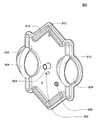
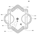
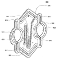
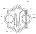
본 발명은 일반적으로 혈액투석을 더 효율적이고, 쉽고, 및/또는 더 적절한 가격으로 만드는 다양한 시스템과 방법을 포함하는 혈액투석 및 유사한 투석 시스템에 관한 것이다. 본 발명의 일 태양은 일반적으로 유체 유동을 위한 새로운 유체 회로에 관한 것이다. 실시예의 일 세트에서, 혈액투석 시스템은 혈류 통로와 투석액 유로를 포함할 수 있고, 투석액 유로는 하나 이상의 균형 회로, 혼합 회로, 및/또는 지시 회로를 포함한다. 일부 경우에, 회로를 준비함으로써 투석액을 준비하는 것은 환자 투석과 분리될 수 있다. 일부 경우에, 회로는 적어도 부분적으로 하나 이상의 카세트 내에 형성될 수 있고, 선택적으로는 도관, 펌프 등과 상호연결된다. 일 실시예에서, 유체 회로 및/또는 다양한 유체 유로는 혈액투석 시스템의 전기 부품으로부터 공간적으로 및/또는 열적으로 적어도 부분적으로 고립될 수 있다. 일부 경우에, 기체 공급원은 투석액 유로 및/또는 투석기와 유체 연통하게 될 수 있고, 작동될 시, 투석액이 투석기를 통과하도록 가압하고 혈류 통로 내의 혈액이 환자에게 되돌아가도록 가압할 수 있다. 이러한 시스템은, 예를 들어, 환자에게 가능한 많은 혈액을 되돌려주는 것이 요구되는 임의의 응급 상황(예를 들어, 정전)에서 유용할 수 있다. 또한, 본 발명의 다른 태양에서, 혈액투서 시스템은 공기와 같은 제어 유체를 사용하여 작동될 수 있는 펌프, 밸브, 혼합기 등과 같은 하나 이상의 유체 취급 장치를 포함할 수 있다. 일부 경우에, 제어 유체는 임의의 경우에 탈거 가능한 외부 펌프 또는 기타 장치를 사용하여 유체 취급 장치로 이송될 수 있다. 일 실시예에서, 하나 이상의 유체 취급 장치는 일반적으로 강성이며(예를 들어, 구상 형상을 갖음), 선택적으로는, 장치를 제1 격실과 제2 격실로 나누는 다이어프램을 장치 내부에 포함한다.The present invention relates generally to hemodialysis and similar dialysis systems that include a variety of systems and methods that make hemodialysis more efficient, easier, and / or more affordable. One aspect of the present invention generally relates to a new fluid circuit for fluid flow. In one set of embodiments, the hemodialysis system may comprise a blood flow path and a dialysis fluid flow path, and the dialysis fluid flow path includes at least one balancing circuit, mixing circuit, and / or indicating circuit. In some cases, preparing the dialysis fluid by preparing the circuit can be separated from the patient dialysis. In some cases, the circuit may be formed, at least in part, in one or more cassettes, and is optionally interconnected with a conduit, pump, and the like. In one embodiment, the fluid circuit and / or the various fluid passageways may be spatially and / or thermally isolated at least partially from the electrical components of the hemodialysis system. In some cases, the gas source may be in fluid communication with the dialysis fluid channel and / or the dialyzer, and when actuated, pressurize the dialysis fluid to pass through the dialyzer and pressurize the blood in the blood flow channel back to the patient. Such a system may be useful, for example, in any emergency (e.g., electrostatic discharge) where it is desired to return as much blood as possible to the patient. Further, in another aspect of the invention, the blood transfusing system may include one or more fluid handling devices, such as pumps, valves, mixers, etc., which may be operated using a control fluid such as air. In some cases, the control fluid may be delivered to the fluid handling device using an external pump or other device that is removable in any event. In one embodiment, the at least one fluid handling device is generally rigid (e.g., having a spherical shape) and optionally includes a diaphragm within the device that divides the device into a first compartment and a second compartment.
Description
본 발명은 일반적으로 혈액투석(hemodialysis) 및 유사한 투석 시스템, 예컨데, 혈액 또는 기타 체액을 체외적으로(extracorporeally) 치료할 수 있는 시스템에 관한 것이다. 임의의 태양에서 시스템은 혈액투석을 더욱 효과적이고, 쉽고, 및/또는 더욱 적절한 가격으로 만들 수 있는 다양한 시스템과 방법을 포함한다.The present invention relates generally to systems capable of extracorporeally treating hemodialysis and similar dialysis systems, such as blood or other body fluids. In any embodiment, the system includes a variety of systems and methods that can make hemodialysis more effective, easier, and / or more affordable.
혈액투석을 비효율적이고, 어렵고, 비싸게 만드는 데에는 많은 요인이 있다. 이러한 요인들에는 혈액투석의 복잡성, 혈액투석에 관련된 안전 문제, 및 혈액투석에 요구되는 투석액의 양이 매우 많다는 것이 있다. 또한, 혈액투석은 전형적으로 숙련된 기술을 요구하는 투석 센터에서 이루어진다. 그러므로, 투석 과정을 더 효율적이고 쉽게 만드는 모든 것들이 치료 비용 또는 환자 결과에 영향을 줄 수 있다.There are many factors that make hemodialysis inefficient, difficult, and expensive. These factors include the complexity of hemodialysis, safety issues related to hemodialysis, and the amount of dialysis fluid required for hemodialysis. In addition, hemodialysis is typically performed at dialysis centers that require skilled techniques. Therefore, anything that makes the dialysis process more efficient and easier can affect the cost of treatment or patient outcomes.
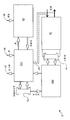
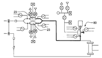
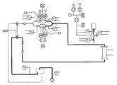
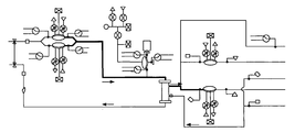
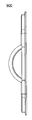
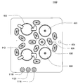
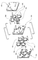
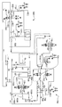
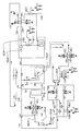
도 1은 혈액투석 시스템의 개략적인 도면이다. 시스템(5)은 2개의 유로들, 혈류 통로(10), 및 투석액 유로(20)를 포함한다. 혈액은 환자로부터 끌어내진다. 혈류 펌프(13)는 혈액을 혈류 통로(10) 주위로 유동시키고, 환자로부터 혈액을 끌어내고, 혈액을 투석기(14)로 통과시키고, 환자에게 되돌아오게 한다. 선택적으로는, 혈액은 환자에게 되돌아가기 전에 필터 및/또는 공기 트랩(air trap: 19)과 같은 다른 구성요소를 통과할 수 있다. 또한, 일부 경우에 항응고제 밸브(12)를 거쳐 항응고제 공급원(11)으로부터 항응고제(anticoagulant)가 공급될 수 있다.Figure 1 is a schematic illustration of a hemodialysis system. The
투석액 펌프(15)는 투석액 공급원(16)으로부터 투석액을 끌어내어 투석기(14)를 통과하게 하고, 이 후에 투석액은 폐기 밸브(18)를 통과하고, 및/또는 투석액 펌프(15)를 거쳐 투석액 공급기로 되돌아 갈 수 있다. 투석액 밸브(17)는 투석액 공급원(16)으로부터의 투석액의 유동을 제어한다. 투석기는 혈류 회로로부터의 혈액이 작은 튜브를 통해 유동하여 튜브 바깥 주위로 투석액 용액이 순환하도록 구성된다. 튜브의 벽을 통해 폐기성 분자(예를 들어, 요소, 크레아티닌 등)와 물을 혈액으로부터 투석액 용액으로 이동시킴으로써 치료가 이루어진다. 치료가 끝나면 투석액 용액은 폐기된다.The
본 발명은 일반적으로 혈액투석 및 유사한 투석 시스템에 관한 것이다. 본 발명의 주제는 일부 경우에 특정 문제에 대한 대안적 해법, 상호 관련된 생산물, 및/또는 하나 이상의 시스템 및/또는 제품의 복수의 다른 사용에 대한 것이다. 본 명세서에 기술된 다양한 시스템과 방법이 혈액투석과 관련되어 기술되었으나, 본 명세서에 기술된 다양한 시스템과 방법은 다른 투석 시스템에 적용되고 및/또는 모든 체외적 시스템에서 혈액여과(hemofiltration), 혈액투석여과(hemodiafiltration) 등과 같이 혈액이나 기타 체액을 치료할 수 있다.The present invention relates generally to hemodialysis and similar dialysis systems. The subject matter of the present invention is in some cases an alternative solution to a particular problem, an interrelated product, and / or a plurality of different uses of one or more systems and / or products. While the various systems and methods described herein have been described in connection with hemodialysis, the various systems and methods described herein may be applied to other dialysis systems and / or may be used in all in vitro systems to perform hemofiltration, Blood or other body fluids such as hemodiafiltration can be treated.
일 태양에서, 시스템은 4개의 유체 통로, 즉, 혈액, 내부 투석액, 외부 투석액, 및 투석액 혼합을 포함한다. 일부 실시예에서, 이러한 4개의 통로는 단일 카세트(cassette)로 결합된다. 다른 실시예에서, 이러한 4개의 통로는 각각의 카세트에 존재한다. 다른 실시예에서, 2개 이상의 유로는 하나의 카세트에 포함된다.In one aspect, the system includes four fluid passages, namely, blood, an internal dialysate, an external dialysate, and a dialysate mix. In some embodiments, these four passageways are combined into a single cassette. In another embodiment, these four passages are present in each cassette. In another embodiment, two or more channels are included in one cassette.
일 실시예에서, 1) 혈류 펌프 카세트, 2) 내부 투석액 카세트, 3) 외부 투석액 카세트, 및 4) 혼합 카세트로 통합된 적어도 2개의 유체 통로를 갖는 혈액투석 시스템이 제공된다. 카세트는 서로 유동적으로 연결될 수 있다. 일부 실시예에서, 이러한 카세트의 하나 이상의 태양은 단일 카세트로 결합될 수 있다.In one embodiment, there is provided a hemodialysis system having at least two fluid passageways integrated into 1) a blood flow pump cassette, 2) an internal dialysate cassette, 3) an external dialysis fluid cassette, and 4) a mixing cassette. The cassettes may be fluidly connected to one another. In some embodiments, one or more aspects of such a cassette may be combined into a single cassette.
또한, 다른 실시예에서, 환자로부터 미처리 혈액이 끌어내져 투석기를 통과하고 치료된 혈액이 환자에게 되돌아가는 혈류 통로를 포함하는 혈액투석 시스템이 제공된다. 혈류 통로는 제거 가능한 카세트에 위치된 적어도 하나의 혈류 펌프를 포함할 수 있다. 또한, 혈액투석 시스템은 혈류 통로의 카세트를 수용하기 위한 제1 수용 구조물과, 투석액이 투석기를 통해 투석액 공급원으로부터 유동하는 투석액 유로와, 투석액 유로의 카세트를 수용하기 위한 제2 수용 구조물과, 각각의 혈류 펌프와 투석액 펌프이 작동하도록 작동 기구로부터 카세트로 제어 유체를 제공하는 제어 유체 통로를 포함한다. 일부 예시에서, 투석액 유로는 제거 가능한 카세트에 위치된 적어도 하나의 투석액 펌프를 포함할 수 있다.In another embodiment, there is also provided a hemodialysis system comprising blood flow passages through which untreated blood is drawn from a patient and passed through a dialyzer and the treated blood returns to the patient. The blood flow passageway may include at least one blood flow pump located in a removable cassette. The hemodialysis system further includes a first receiving structure for receiving the cassette of the blood flow passage, a dialysis fluid channel through which the dialysis fluid flows from the dialysis fluid supply source through the dialyzer, a second receiving structure for receiving the cassette of the dialysis fluid channel, And a control fluid passage for providing a control fluid from the operating mechanism to the cassette so that the blood flow pump and the dialysis fluid pump operate. In some instances, the dialysis fluid channel may include at least one dialysis fluid pump located in a removable cassette.
다른 실시예에서, 혈액투석 시스템이 기재된다. 이 실시예에서 혈액투석 시스템은 미처리 혈액이 환자로부터 끌어내져 투석기를 통과하고 치료된 혈액이 환자에게 되돌아가는 혈류 통로를 포함한다. 혈류 통로는 적어도 하나의 혈액 밸브를 포함할 수 있다. 또한, 혈액투석 시스템은 작동 기구로부터 혈액 밸브를 작동시키기 위한 혈액 밸브로 제어 유체를 제공하는 제어 유체 통로를 포함할 수 있으며, 투석액 혼합 시스템은 (적어도 하나의 투석기 밸브를 포함하는) 투석기와 가열 수단 또는 투석액을 가열하기 위한 히터에 유동적으로 연결된다.In another embodiment, a hemodialysis system is described. In this embodiment, a hemodialysis system includes a blood flow path through which untreated blood is drawn from the patient and passed through the dialyzer and the treated blood returns to the patient. The blood flow passage may include at least one blood valve. The hemodialysis system may also include a control fluid pathway providing a control fluid to a blood valve for actuating a blood valve from an operating device, wherein the dialysis fluid mixing system includes a dialyzer (including at least one dialyzer valve) Or is fluidly connected to a heater for heating the dialysis fluid.
다른 실시예에서, 미처리 혈액이 환자로부터 끌어내져 투석기를 통과하고 치료된 혈액이 환자에게 되돌아가는 혈류 통로를 포함하는 혈액투석 시스템이 기재된다. 혈류 통로는 적어도 하나의 혈류 펌프를 포함할 수 있다. 또한, 혈액투석 시스템은 투석액이 투석액 공급원으로부터 투석기를 통해 유동하는 투석액 유로를 포함할 수 있다. 투석액 유로는 적어도 하나의 공압식 펌프를 포함할 수 있다.In another embodiment, a hemodialysis system is described wherein the untreated blood is withdrawn from the patient, passed through a dialyzer, and the treated blood returns to the patient. The blood flow passage may include at least one blood flow pump. In addition, the hemodialysis system may include a dialysis fluid channel through which the dialysis fluid flows from the dialysis fluid supply source through the dialyzer. The dialysate flow path may include at least one pneumatic pump.
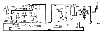
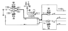
일 태양에서, 본 발명은 혈액투석 시스템에 관한 것이다. 일 실시예의 세트에서, 혈액투석 시스템은, 혈류 통로와, 내부 투석액 유로를 형성하는 제1 카세트와, 혈류 통로와 유체 연통하는 투석기와, 외부 투석액 유로를 형성하는 제2 카세트와, 제1 카세트를 제2 카세트에 유동적으로 연결하는 필터를 포함한다.In one aspect, the present invention relates to a hemodialysis system. In one set of embodiments, a hemodialysis system includes a blood flow path, a first cassette that forms an internal dialysate flow path, a dialysis machine in fluid communication with the blood flow path, a second cassette that forms an external dialysis fluid flow path, And a filter for fluidly connecting to the second cassette.
다른 실시예의 세트에서, 혈액투석 시스템은, 혈류 통로와, 내부 투석액 유로와, 혈류 통로와 내부 투석액 유로와 유체 연통하는 투석기와, 외부 투석액 유로와, 내부 투석액 유로와 외부 투석액 유로를 유동적으로 연결시키는 필터와, 내부 투석액 유로를 통해 투석액을 펌핑하는 제1 투석액 펌프와, 외부 투석액 유로를 통해 투석액을 펌핑하는 제2 투석액 펌프를 포함하며, 제2 투석액 펌프와 제1 투석액 펌프는 작동가능하게 연결되어 내부 투석액 유로를 통한 유동이 외부 투석액 유로를 통한 유동과 대체로 동일하게 한다.In another set of embodiments, the hemodialysis system includes a blood flow path, an internal dialysate flow path, a dialysis machine in fluid communication with the blood flow path and the internal dialysis fluid flow path, an external dialysis fluid flow path, and an internal dialysis fluid flow path, A first dialysis solution pump for pumping the dialysis solution through the internal dialysis solution flow path and a second dialysis solution pump for pumping the dialysis solution through the external dialysis solution flow passage, wherein the second dialysis solution pump and the first dialysis solution pump are operatively connected The flow through the internal dialysate flow path is made substantially the same as the flow through the external dialysis fluid flow path.
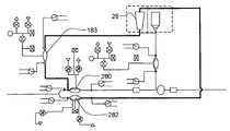
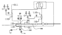
다른 실시예의 세트에서, 혈액투석 시스템은, 혈액이 환자로부터 끌어내져 투석기를 통과하는 혈류 통로와, 투석액이 투석액 공급원으로부터 투석기를 통해 유동하는 투석액 유로를 포함한다. 일부 경우에, 투석액 유로는, 투석기를 통과하는 투석액의 양을 제어하는 균형 카세트(balancing cassette)와, 물로부터 투석액을 형성하는 혼합 카세트(mixing cassette)와, 물을 물 공급원으로부터 혼합 카세트로 이동시켜 혼합 카세트로부터 균형 카세트로 투석액을 이동시키는 지시 카세트(directing cassette)를 포함한다.In another set of embodiments, a hemodialysis system includes a blood flow path through which blood is drawn from the patient and through the dialyzer, and a dialysis fluid flow path through which the dialysis fluid flows from the dialysis fluid source through the dialyzer. In some cases, the dialysis fluid channel may include a balancing cassette to control the amount of dialysis fluid passing through the dialyzer, a mixing cassette to form a dialysis fluid from water, and water to a mixing cassette And a directing cassette for transferring the dialysis liquid from the mixed cassette to the balance cassette.
다른 실시예의 세트에서, 혈액투석 시스템은, 지시 카세트와 균형 카세트를 포함하는 카세트 시스템을 포함한다. 일부 경우에, 지시 카세트는 물 공급원으로부터 혼합 카세트로 물을 유도할 수 있고, 혼합 카세트로부터 균형 카세트로 투석액을 유도할 수 있으며, 혼합 카세트는 지시 카세트로부터의 물을 투석액 공급원 전구체와 혼합하여 전구체를 생성할 수 있고, 균형 카세트는 투석기를 통과하는 투석액의 양을 제어할 수 있다.In another set of embodiments, the hemodialysis system includes a cassette system including an indicator cassette and a balance cassette. In some cases, the indicator cassette can direct water from the water source to the mixing cassette and direct the dialysis liquid from the mixing cassette to the balance cassette, wherein the mixing cassette mixes water from the indicator cassette with the dialysate source precursor to form a precursor And the balance cassette can control the amount of dialysis fluid passing through the dialyzer.
일 실시예의 세트에서, 혈액투석 시스템은 혈액이 환자로부터 끌어내져 투석기를 통과하는 혈류 통로를 포함하고, 혈류 통로는 혈류 펌프와, 투석액이 투석액 공급원으로부터 투석기를 통해 유동하는 투석액 유로를 포함하고, 투석액 유로는 투석액 펌프와, 제어 유체가 혈류 펌프와 투석액 펌프를 작동시키는 제어 유체 통로를 포함한다.In one set of embodiments, a hemodialysis system includes a blood flow path through which blood is drawn from a patient and passes through a dialyzer, the blood flow path includes a blood flow pump, and a dialysis fluid flow path through which the dialysis fluid flows from the dialysis fluid supply source through the dialyzer, The flow path includes a dialysis fluid pump and a control fluid passage through which the control fluid operates the blood flow pump and the dialysis fluid pump.
다른 실시예의 세트에서, 혈액투석 시스템은 혈액이 환자로부터 끌어내져 투석기를 통과하는 혈류 통로와, 투석액이 투석액 공급원으로부터 투석기를 통해 유동하는 투석액 유로를 포함한다. 일부 경우에, 투석액 유로는 적어도 하나의 공압식 펌프를 포함한다.In another set of embodiments, the hemodialysis system includes a blood flow path through which blood is drawn from the patient and through the dialyzer, and a dialysis fluid flow path through which the dialysis fluid flows from the dialysis fluid source through the dialyzer. In some cases, the dialysis fluid flow path includes at least one pneumatic pump.
다른 실시예의 세트에서, 혈액투석 시스템은, 펌프 챔버(pumping chamber)와 작동 챔버(actuation chamber)를 포함하는 제1 펌프와, 펌프 챔버와 작동 챔버를 포함하는 제2 펌프와, 제1 및 제2 펌프의 작동 챔버 각각과 유체 연통하는 제어 유체와, 제1 및 제2 펌프의 작동을 제어하기 위해 제어 유체를 가압할 수 있는 제어기를 포함한다.In another set of embodiments, a hemodialysis system includes a first pump comprising a pumping chamber and an actuation chamber, a second pump comprising a pump chamber and an operating chamber, A control fluid in fluid communication with each of the actuating chambers of the pump, and a controller able to pressurize the control fluid to control the operation of the first and second pumps.
다른 실시예의 세트에서, 혈액투석 시스템은 밸브 챔버(valving chamber)와 작동 챔버를 포함하는 제1 밸브와, 밸브 챔버와 작동 챔버를 포함하는 제2 밸브와, 제1 및 제2 밸브의 작동 챔버 각각과 유체 연통하는 제어 유체와, 제1 및 제2 밸브의 작동을 제어하기 위해 제어 유체를 가압할 수 있는 제어기를 포함한다.In another set of embodiments, the hemodialysis system may include a first valve including a valving chamber and an actuating chamber, a second valve including a valve chamber and an actuating chamber, and a second valve including a first chamber and a second chamber, And a controller able to pressurize the control fluid to control operation of the first and second valves.
실시예의 일 세트에서, 혈액투석 시스템은 혈액이 환자로부터 끌어내져 투석기를 통과하는 혈류 통로와, 혈류 통로의 적어도 일부를 포함하는 카세트와, 카세트와 일체형으로 형성된 스파이크(spike)를 포함하고, 스파이크는 유체 약병(vial)을 수용하며, 일체형으로 형성된 스파이크는 카세트 내부의 혈류 통로와 유체 연통한다.In one set of embodiments, a hemodialysis system includes a blood flow path through which blood is drawn from the patient and through the dialyzer, a cassette comprising at least a portion of the blood flow path, and a spike formed integrally with the cassette, A fluid receiving vial is formed and the integrally formed spike is in fluid communication with the blood flow passageway within the cassette.
다른 실시예의 세트에서, 혈액투석 시스템은 미처리 혈액이 환자로부터 끌어내져 투석기를 통과하는 혈류 통로와, 투석액이 투석액 공급원으로부터 투석기를 통해 유동하는 투석액 유로와, 투석액이 투석액 유로로부터 혈류 통로로 이동하게 하는 투석기와, 투석액 유로와 유체 연통하는 기체 공급원을 포함하고, 작용 시, 기체 공급원으로부터의 기체는 투석액을 투석기로 통과시키고 혈류 통로 내의 혈액을 환자에게로 다시 가압된다.In another set of embodiments, the hemodialysis system includes a blood flow path through which the untreated blood is drawn from the patient and passes through the dialyzer, a dialysis fluid flow path through which the dialysis fluid flows from the dialysis fluid supply source through the dialyzer, and a dialysis fluid flow from the dialysis fluid flow path to the blood flow path A dialysis machine and a gas supply in fluid communication with the dialysis fluid flow path, wherein the gas from the gas supply passes the dialysis fluid through the dialyzer and the blood in the blood flow path is pressurized back to the patient.
다른 실시예의 세트에서, 혈액투석 시스템은, 미처리 혈액이 환자로부터 끌어내져 투석기를 통과하는 혈류 통로와, 투석액이 투석액 공급원으로부터 투석기를 통해 유동하는 투석액 유로와, 투석액이 투석액 유로로부터 혈류 통로로 이동하게 하는 투석기와, 유체 공급원과, 유체 공급원과 유체 연통하는 챔버와, 투석액 유로를 포함하고, 챔버는 유체 공급원의 의 유체를 투석액 유로의 투석액으로부터 분리시키는 다이어프램을 갖고, 챔버 내의 투석액에 대해 다이어프램을 가압하기 위해 유체 공급원을 가압하는 가압 장치 포함하며, 이에 따라 투석액이 투석기를 통과하고 혈류 통로 내의 혈액이 환자에게로 다시 가압되게 된다.In another set of embodiments, the hemodialysis system may include a blood flow path through which untreated blood is drawn from the patient and passes through the dialyzer, a dialysis fluid flow path through which the dialysis fluid flows from the dialysis fluid supply source through the dialyzer, and a dialysis fluid that flows from the dialysis fluid flow path to the blood flow path The chamber having a diaphragm for separating the fluid of the fluid supply source from the dialysate of the dialysate flow passage, and the diaphragm is pressed against the dialysis liquid in the chamber, , So that the dialysis fluid passes through the dialyzer and the blood in the blood flow path is pressed back to the patient.
다른 실시예의 세트에서, 혈액투석 시스템은 미처리 혈액이 환자로부터 끌어내져 투석기를 통과하는 혈류 통로와, 투석액이 투석액 공급원으로부터 투석기를 통해 유동하는 투석액 유로를 포함하고, 투석기 유로와 혈류 통로는 유체 연통하며, 투석액 유로 내의 투석액이 혈류 통로로 유동하게 가압할 수 있는 압력 장치를 포함한다.In another set of embodiments, the hemodialysis system includes a blood flow path through which untreated blood is withdrawn from the patient and passes through the dialyzer, and a dialysis fluid flow path through which the dialysis fluid flows from the dialysis fluid supply source through the dialyzer, wherein the dialysis fluid flow path and the blood flow path are in fluid communication And a pressure device capable of pressurizing the dialysis fluid in the dialysis fluid channel to flow into the blood flow passage.
다른 실시예의 세트에서, 혈액투석 시스템은, 제어 유체에 의해 작동되는 정변위 펌프(positive-displacement pump)와, 제어 유체 펌프로 정변위 펌프에 유동적으로 연결되는 유체 도관과, 제어 유체 펌프를 포함하는 제2 하우징을 포함하고, 제2 하우징은 제1 하우징으로부터 탈거 가능하다.In another set of embodiments, a hemodialysis system includes a positive-displacement pump actuated by a control fluid, a fluid conduit fluidly connected to the positive displacement pump by a control fluid pump, and a control fluid pump The second housing includes a second housing, and the second housing is detachable from the first housing.
다른 실시예의 세트에서, 혈액투석 시스템은 격리벽에 의해 분리된 제1 구획과 제2 구획을 포함하는 하우징을 포함하고, 제1 구획은 적어도 약 80℃의 온도에서 소독될 수 있고, 제2 구획은 전자 부품을 포함하여 제1 구획이 적어도 약 80℃의 온도로 가열될 시 60℃ 초과의 온도로 가열된다.In another set of embodiments, the hemodialysis system includes a housing comprising a first compartment and a second compartment separated by an isolation wall, wherein the first compartment can be disinfected at a temperature of at least about 80 캜, Including the electronic component, is heated to a temperature greater than 60 占 폚 when the first compartment is heated to a temperature of at least about 80 占 폚.
다른 실시예의 세트에서, 혈액투석 시스템은, 미처리 혈액이 환자로부터 끌어내져 투석기를 통과하는 혈류 통로로서 적어도 하나의 혈액 밸브를 포함하는 혈류 통로와, 혈액 밸브를 작동시키기 위해 작동 기구로부터 혈액 밸브로 제어 유체를 제공하는 제어 유체 통로와, 투석기에 유동적으로 연결되고 적어도 하나의 투석기 밸브를 포함하는 투석액 혼합 시스템과, 투석액을 가열하기 위한 히터를 포함한다.In another set of embodiments, a hemodialysis system includes a blood flow path including at least one blood valve as a blood flow path through which untreated blood is withdrawn from the patient and passes through the dialyzer, and a blood valve A control fluid passage providing fluid, a dialysate mixing system fluidly connected to the dialyzer and including at least one dialyzer valve, and a heater for heating the dialysate.
본 발명의 다른 태양은 밸브 시스템(vlaving system)에 관한 것이다. 실시예의 일 세트에서, 밸브 시스템은, 복수의 밸브를 포함하는 밸브 하우징으로서 적어도 2개의 밸브 각각은 밸브 챔버와 작동 챔버를 포함하고 작동 챔버 내의 제어 유체에 의해 작동 가능한, 밸브 하우징과, 베이스 유닛으로부터 제어 유체와 유체 연통하도록 복수의 유체 인터페이스 포트(fluid-interface port)를 갖는 제어 하우징과, 밸브 하우징과 제어 하우징 사이로 연장되는 복수의 튜브를 포함하고, 각 튜브는 하나의 유체 인터페이스 포트와 적어도 하나의 작동 챔버 사이에 유체 연통이 되게하고, 베이스 유닛은 유체 인터페이스 포트 내의 제어 유체를 가압함으로써 밸브를 작동시킬 수 있다.Another aspect of the invention relates to a vlaving system. In one set of embodiments, the valve system includes a valve housing including a plurality of valves, wherein each of the at least two valves includes a valve chamber and an actuating chamber and is operable by a control fluid in the actuating chamber; A control housing having a plurality of fluid-interface ports in fluid communication with the control fluid, and a plurality of tubes extending between the valve housing and the control housing, each tube having a fluid interface port and at least one Fluid communication between the operating chambers, and the base unit can actuate the valve by pressurizing the control fluid in the fluid interface port.
일 실시예의 세트에서, 본 발명은, 제1 플레이트와, 제1 플레이트를 측면 대면하는 만입부를 갖는 제2 플레이트로서 만입부는 만입부 내에 형성된 홈(groove)을 갖고 홈은 제1 플레이트를 대면하는 방향으로 개방되는, 제2 플레이트와, 제3 플레이트를 포함하며, 제2 플레이트는 제1 플레이트와 제3 플레이트 사이에 위치하고, 제1 플레이트와 제2 플레이트 사이의 만입부에 위치하는 다이어프램으로서 홈에 유지되는 림을 갖는, 다이어프램을 포함하는, 밸브에 관한 것이다. 제2 플레이트는 폐쇄된 밸브 시트(valve seat)를 밀봉하기 위해 다이어프램이 공기압에 의해 가압되도록 배열되는 밸브 시트를 포함할 수 있으며, 홈은 밸브 시트를 둘러싼다. 일부 경우에, 밸브 입구와 밸브 출구는 제2 플레이트와 제3 플레이트 사이에 형성된다. 일부 실시예에서, 공기압을 제공하기 위한 통로가 제1 플레이트와 제2 플레이트 사이에 형성된다.In a set of one embodiment, the present invention is characterized in that the groove has a groove formed in the indentation portion which is embossed as a second plate having a first plate and a depressed portion facing the first plate laterally, And the second plate is positioned between the first plate and the third plate and is held in the groove as a diaphragm located at the indentation between the first plate and the second plate, Wherein the diaphragm has a rim that is in contact with the diaphragm. The second plate may include a valve seat arranged such that the diaphragm is urged by air pressure to seal a closed valve seat, the groove surrounding the valve seat. In some cases, the valve inlet and the valve outlet are formed between the second plate and the third plate. In some embodiments, a passage for providing air pressure is formed between the first plate and the second plate.
본 발명의 다른 태양은 펌프 시스템에 관한 것이다. 실시예의 일 세트에서, 펌프 시스템은, 복수의 펌프를 포함하는 펌프 하우징으로서 펌프들 중 적어도 2개 각각은 펌프 챔버와 작동 챔버를 갖고 적어도 2개의 펌프 각각은 작동 챔버 내의 제어 유체에 의해 작동 가능한, 펌프 하우징과, 베이스 유닛으로부터 제어 유체와 유체 연통시키기 위한 복수의 유체 인터페이스 포트를 갖는 제어 하우징과, 펌프 하우징과 제어 하우징 사이로 연장되는 복수의 튜브로서 각 튜브는 유체 인터페이스 포트들 중 하나와 작동 챔버들 중 적어도 하나 사이에 유체 연통을 제공하는, 복수의 튜브를 포함하여, 베이스 유닛이 유체 인터페이스 포트 내의 제어 유체를 가압함으로써 펌프를 작동시킬 수 있게 한다.Another aspect of the invention relates to a pump system. In one set of embodiments, the pump system comprises a pump housing including a plurality of pumps, wherein each of at least two of the pumps has a pump chamber and an operation chamber, and each of the at least two pumps is operable by a control fluid in the operation chamber, A control housing having a pump housing, a control housing having a plurality of fluid interface ports for fluidly communicating with the control fluid from the base unit, a plurality of tubes extending between the pump housing and the control housing, each tube having one of the fluid interface ports, A plurality of tubes that provide fluid communication between at least one of the fluid interface ports to enable the base unit to operate the pump by pressurizing the control fluid in the fluid interface port.
다른 태양에서 본 발명은 일반적으로 펌프 카세트에 관한 것이다. 일 세트이 실시예에서, 펌프 카세트는, 적어도 하나의 유체 입구와, 적어도 하나의 유체 출구와, 적어도 하나의 유체 입구와 적어도 하나의 유체 출구를 연결하는 유로와, 상기 카세트에 약병을 부착시키기 위한 스파이크를 포함한다. 스파이크는 일부 경우에 유로와 유체 연통할 수 있다.In another aspect, the present invention generally relates to a pump cassette. One set In this embodiment, the pump cassette comprises at least one fluid inlet, at least one fluid outlet, a flow passage connecting at least one fluid inlet and at least one fluid outlet, and a spike for attaching the vial to the cassette . The spike may in some cases be in fluid communication with the flow path.
일 태양에서 본 발명은 일발적으로 목표물로의 그리고 목표물로부터의 유동을 균형 잡기 위한 펌프 카세트에 관한 것이다. 일 세트의 실시예에서, 펌프 카세트는 카세트 입구와, 목표물로의 공급 라인과, 목표물로부터의 복귀 라인과, 카세트 출구와, 유체가 카세트 입구로부터 공급 라인으로 그리고 복귀 라인으로부터 카세트 출구로 유동하게 하는 펌프 기구와, 균형 챔버를 포함한다. 일부 경우에, 펌프 기구는, 펌핑 공간(pumping volume)을 형성하고 입구와 출구를 갖는 강성 만곡 벽(curved wall)과, 펌핑 공간 내에 장착된 펌프 다이어프램과, 포드 펌프(pod pump)를 공압식 작동 시스템에 연결하는 작동 포트를 포함하고, 다이어프램은 유체를 펌핑 공간 내로 그리고 펌핑 공간 바깥으로 가압하도록 작동될 수 있고, 펌프 다이어프램은 공압식 작동 시스템과 유체 연통하는 기체로부터 유체를 분리시킨다. 임의의 경우에, 균형 챔버는 균형 공간(balance volume)을 형성하는 강성 만곡 벽과, 균형 공간 내부에 장착된 균형 다이어프램을 포함하고, 균형 다이어프램은 균형 공간을 공급측과 복귀측으로 분리시키고, 공급측과 복귀측 각각은 입구와 출구를 갖는다. 일부 경우에, 카세트 입구로부터의 유체는 공급측 입구로 유동하고, 공급측 출구로부터의 유체는 공급 라인으로, 복귀라인으로부터의 유체는 복귀측 입구로, 복귀측 출구로부터의 유체는 카세트 출구로 유동한다.In one aspect, the present invention relates to a pump cassette for uniquely balancing flow from and to a target. In one set of embodiments, the pump cassette includes a cassette inlet, a supply line to the target, a return line from the target, a cassette outlet, and a fluid outlet to allow fluid to flow from the cassette inlet to the supply line and from the return line to the cassette outlet A pump mechanism, and a balance chamber. In some cases, the pump mechanism includes a rigid curved wall defining a pumping volume and having an inlet and an outlet, a pump diaphragm mounted within the pumping space, and a pod pump coupled to a pneumatic actuation system Wherein the diaphragm is operable to press fluid into and out of the pumping space and the pump diaphragm separates fluid from the gas in fluid communication with the pneumatic actuation system. In any case, the balance chamber comprises a rigid curved wall defining a balance volume and a balance diaphragm mounted within the balance space, the balance diaphragm separating the balance space into a feed side and a return side, Each side has an inlet and an outlet. In some cases, the fluid from the cassette inlet flows to the feed side inlet, the fluid from the feed side outlet flows to the feed line, the fluid from the return line flows to the return side inlet, and the fluid from the return side outlet flows to the cassette outlet.
실시예의 다른 세트에서, 펌프 시스템은, 시스템 입구와, 목표물로의 공급 라인과, 목표물로부터의 복귀 라인과, 시스템 출구와, 시스템 입구로부터 공급 라인으로 그리고 복귀 라인으로부터 시스템 출구로 유체가 유동하게 하는 펌프 기구와, 균형 챔버를 포함한다.In another set of embodiments, the pump system includes a system inlet, a supply line to the target, a return line from the target, a system outlet, and a flow path from the system inlet to the supply line and from the return line to the system outlet A pump mechanism, and a balance chamber.
일 실시예에서, 펌프 기구는 강성 구상 벽(spheroid wall)을 포함하는데, 강성 구상 벽은 펌핑 공간을 형성하고, 입구와, 출구와, 내부에서 구상 벽으로 장착되는 펌프 다이어프램과, 포드 펌프를 공압식 작동 시스템에 연결하는 포트를 갖고, 다이어프램은 유체를 펌핑 공간으로 그리고 펌핑 공간 밖으로 가압하기 위해 작동될 수 있다. 일부 경우에, 펌프 다이어프램은 공압식 작동 시스템과 유체 연통하는 기체로부터 유체를 분리시킨다.In one embodiment, the pump mechanism includes a spheroid wall, the rigid spherical wall defining a pumping space and having an inlet, an outlet, a pump diaphragm mounted with a spherical wall therein, and a pneumatic The diaphragm can be actuated to pressurize the fluid into and out of the pumping space. In some cases, the pump diaphragm separates the fluid from the gas in fluid communication with the pneumatic actuation system.
임의의 경우에, 균형 챔버는 균형 공간을 형성하는 강성 구상 벽과, 내부에서 구상 벽으로 장착되는 균형 다이어프램을 포함한다. 일 실시예에서, 균형 다이어프램은 균형 공간을 공급측과 복귀측으로 분리시키고, 공급측과 복귀측 각각은 입구와 출구를 갖는다. 일부 경우에, 시스템 입구로부터의 유체는 공급측 입구로 유동하고, 공급측 출구로부터의 유체는 공급 라인으로 유동하고, 복귀 라인으로부터의 유체는 복귀측 입구로 유동하고, 복귀측 출구로부터의 유체는 시스템 출구로 유동한다. 또한, 펌프 기구는 공급측과 히송측의 입구와 출구 각각에 위치하는 밸브 기구를 포함할 수 있다. 밸브 기구는 공압식으로 작동될 수 있다.In any case, the balance chamber includes a rigid spherical wall defining a balance space and a balance diaphragm mounted within the spherical wall. In one embodiment, the balance diaphragm separates the balance space into a supply side and a return side, each of the supply side and the return side having an inlet and an outlet. In some cases, the fluid from the system inlet flows to the feed side inlet, the fluid from the feed side outlet flows to the feed line, the fluid from the return line flows to the return side inlet, Lt; / RTI > The pump mechanism may also include a valve mechanism located at the inlet and outlet of the feed side and the feed side, respectively. The valve mechanism may be operated pneumatically.
본 발명의 다른 태양은 카세트에 관한 것이다. 일 세트의 실시예에서, 카세트는 제1 입구를 제1 출구로 연결시키는 제1 유로와, 제2 입구를 제2 출구로 연결시키는 제2 유로와, 제2 유로의 적어도 일부분을 통해 유체를 펌핑할 수 있는 펌프와, 강성 용기를 제1 구획과 제2 구획으로 나누는 다이어프램을 포함하는 강성 용기를 포함하는 균형 챔버로서 각 균형 챔버의 제1 구획은 제1 유로와 유체 연통하고 제2 구획은 제2 유로와 유체 연통하는, 적어도 2개의 균형 챔버를 포함한다.Another aspect of the invention relates to a cassette. In one set of embodiments, the cassette includes a first flow path for connecting the first inlet to the first outlet, a second flow path for connecting the second inlet to the second outlet, and a second flow path for pumping the fluid through at least a portion of the second flow path. And a rigid vessel including a diaphragm that divides the rigid vessel into a first section and a second section, the first section of each balance chamber being in fluid communication with the first flow path, And at least two balance chambers in fluid communication with the two flow paths.
실시예의 다른 세트에서, 카세트는, 제1 입구를 제1 출구에 연결하는 제1 유로와, 제2 입구를 제2 출구에 연결하는 제2 유로와, 제어 유체 통로와, 강성 용기를 제1 구획과 제2 구획으로 나누는 다이어프램을 포함하는 강성 용기를 포함하는 펌프로서 각 펌프의 제1 구획은 제어 유체 통로와 유체 연통하고 제2 구획은 제2 유로와 유체 연통하는, 적어도 2개의 펌프와, 제1 유로와 제2 유로 사이의 유동을 균형 잡을 수 있는 균형 챔버를 포함한다.In another set of embodiments, the cassette includes a first flow path connecting the first inlet to the first outlet, a second flow path connecting the second inlet to the second outlet, a control fluid passageway, Wherein the first section of each pump is in fluid communication with the control fluid path and the second section is in fluid communication with the second flow path, And a balance chamber capable of balancing the flow between the first and second flow paths.
실시예의 다른 세트에서, 카세트는, 제1 입구를 제1 출구에 연결하는 제1 유로와, 제2 입구를 제2 출구에 연결하는 제2 유로와, 강성 용기를 제1 구획과 제2 구획으로 나누는 다이어프램을 포함하는 강성 용기를 포함한다. 일부 경우에, 제1 구획은 제1 유로와 유체 연통하고, 제2 구획은 제2 유로와 유체 연통한다.In another set of embodiments, the cassette includes a first flow path connecting the first inlet to the first outlet, a second flow path connecting the second inlet to the second outlet, and a second flow path connecting the rigid vessel to the first and second compartments Lt; RTI ID = 0.0 > diaphragm. ≪ / RTI > In some cases, the first compartment is in fluid communication with the first flow path, and the second compartment is in fluid communication with the second flow path.
본 발명의 다른 태양은 일반적으로 펌프에 관한 것이다. 실시예의 일 세트에서, 펌프는 제1 강성 구성요소와, 내부에 형성된 홈을 제1 플레이트 대면측 상에 갖는 제2 강성 구성요소로서 홈은 제1 강성 구성요소를 대면하는 방향으로 개방되는, 제2 강성 구성요소와, 림을 갖는 다이어프램으로서 림은 림에 대한 제1 강성 구성요소에 의한 접촉 없이 그루부 내에 끼워지는 마찰력으로 홈 내에 유지되는, 다이어프램을 포함한다. 일부 경우에, 제1 및 제2 강성 구성요소는 적어도 부분적으로 포드 펌프 챔버(pod-pump chamber)를 형성하고, 포드 펌프 챔버는 분리된 챔버로 다이어프램에 의해 나누어지고, 적어도 부분적으로 포드 펌프 챔버로의 유로는 더 형성하고, 홈은 포드 펌프 챔버를 둘러싼다.Another aspect of the invention relates generally to pumps. In one set of embodiments, the pump includes a first rigid component and a second rigid component having a groove formed therein on the first plate facing side, wherein the groove is open in a direction facing the first rigid component, A diaphragm component and a diaphragm having a rim, wherein the rim is held in the groove with frictional forces that fit within the groove without contact by the first rigid component to the rim. In some cases, the first and second rigid components form at least in part a pod-pump chamber, the pod pump chamber is divided by a diaphragm into a separate chamber, and at least partially into a pod pump chamber And the groove surrounds the pod pump chamber.
실시예의 다른 세트에서, 펌프는 강성 용기를 제1 구획과 제2 구획으로 나누는 가요성 다이어프램을 포함하는 실절적으로 구상인 용기를 포함하고, 제1 구획과 제2 구획은 서로 유체 연통하지 않으며, 제1 구획으로 진입하는 유체로 인한 다이어프램의 이동은 제2 구획 내부의 유체의 펌핑이 일어나게 한다.In another set of embodiments, the pump includes a substantially spherical container comprising a flexible diaphragm that divides the rigid container into a first compartment and a second compartment, wherein the first compartment and the second compartment are not in fluid communication with each other, Movement of the diaphragm due to fluid entering the first compartment causes pumping of fluid within the second compartment.
실시예의 다른 세트에서, 펌프는 왕복식 정변위 펌프(reciprocating positive-displacement pump)이다. 일 실시예에서, 펌프는 강성 챔버 벽과, 강성 챔버 벽에 부착된 가요성 다이어프램으로서 가요성 다이어프램과 강성 챔버 벽이 펌프 챔버를 형성하는, 가요성 다이어프램과, 강성 챔버 벽을 통해 펌프 챔버로 유동을 유도하는 입구와, 강성 챔버 벽을 통해 펌프 챔버 바깥으로 유동을 유도하는 출구와, 다이어프램의 이동을 제한하고 펌프 챔버의 최대 용적을 제한하는 강성 제한 벽으로서 가요성 다이어프램과 강성 제한 벽이 작동 챔버를 형성하는, 강성 제한 벽과, 간헐적으로 작동 챔버에 제어 압력을 제공하는 공압식 작동 시스템을 포함한다. 일부 경우에, 공압식 작동 시스템은, 작동 챔버의 압력을 측정하기 위한 작동 챔버 압력 변환기와, 제1 압력을 갖는 기체 저장기(reservoir)와, 작동 챔버와 기체 저장기 사이의 기체 유동을 가변적으로 제한하기 위한 가변 밸브 기구와, 작동 챔버 압력 변환기로부터 압력 정보를 받아 작동 챔버 내에 제1 압력 미만의 제어 압력을 생성하도록 가변 밸브를 제어하는 제어기를 포함한다.In another set of embodiments, the pump is a reciprocating positive-displacement pump. In one embodiment, the pump comprises a rigid chamber wall, a flexible diaphragm attached to the rigid chamber wall, the flexible diaphragm defining a pump chamber with the rigid chamber wall, and a flexible diaphragm, An outlet for leading the flow out of the pump chamber through the rigid chamber wall and a rigid restrictor wall for restricting movement of the diaphragm and limiting the maximum volume of the pump chamber, A rigid limiting wall, and a pneumatic actuation system that provides control pressure to the actuation chamber intermittently. In some cases, the pneumatic actuation system includes an operating chamber pressure transducer for measuring the pressure of the operating chamber, a gas reservoir having a first pressure, and a gas reservoir for variably limiting the gas flow between the operating chamber and the gas reservoir. And a controller for receiving the pressure information from the operating chamber pressure transducer and controlling the variable valve to produce a control pressure less than the first pressure in the operating chamber.
본 발명의 다른 태양은 방법에 관한 것이다. 일 세트의 실시에에서, 방법은, 펌프 챔버와 작동 챔버를 포함하는 제1 펌프와 펌프 챔버와 작동 챔버를 포함하는 제2 펌프를 포함하는 제2 펌프를 제공하는 단계와, 공통 유체를 제1 및 제2 펌프 각각의 작동 챔버로 가압하는 단계와, 제1 및 제2 펌프 각각을 통해 유체를 펌핑하도록 공통 유체를 가압하는 단계를 포함한다.Another aspect of the invention relates to a method. In one set of implementations, the method includes providing a second pump comprising a first pump comprising a pump chamber and an operation chamber, and a second pump comprising a pump chamber and an operation chamber, And the second pump, respectively, and pressing the common fluid to pump the fluid through each of the first and second pumps.
실시예의 다른 세트에서, 방법은, 밸브 챔버와 작동 챔버를 포함하는 제1 밸브와 밸브 챔버와 작동 챔버를 포함하는 제2 밸브를 제공하는 단계와, 제1 및 제2 밸브 각각의 작동 챔버로 공통 유체를 가압하는 단계와, 제1 및 제2 밸브 각각을 통해 적어도 부분적으로 유체 유동을 억제하기 위해 공통 유체를 가압하는 단계를 포함한다.In another set of embodiments, the method includes providing a first valve including a valve chamber and an operation chamber, a second valve including a valve chamber and an operation chamber, Pressurizing the fluid and pressurizing the common fluid to at least partially inhibit fluid flow through the first and second valves, respectively.
실시예의 다른 세트에서, 방법은, 투석기의 클리어런스(clearance)를 측정하는 방법이며, 투석기는 혈류 통로에 위치하고, 이를 통해 미처리 혈액이 환자로부터 끌어내져 투석기를 통과하고, 투석액 유로를 통해서는 투석액이 투석액 공급원으로부터 투석기를 통해 유동할 수 있으며, 혈류 통로는 투석기 내의 멤브레인에 의해 투석액 유로로부터 분리된다. 일 실시예에서, 방법은, 투석액 유로를 통해 투석기로 액체를 가압하여 멤브레인이 습윤한 상태를 유지하고 멤브레인을 통한 기체의 유동을 방지하는 단계와, 기체를 혈류 통로를 통해 투석기로 가압하여 투석기 내의 혈류 통로를 기체로 충진시키는 단계와, 투석기 내의 기체의 용적을 측정하는 단계와, 투석기 내에서 측정된 기체의 용적에 기초하여 투석기의 클리어런스를 계산하는 단계를 포함한다.In another set of embodiments, the method is a method of measuring the clearance of a dialyzer, wherein the dialyzer is located in a blood flow passage through which untreated blood is drawn from the patient and passes through the dialyzer, From the source, through the dialyzer, and the blood flow passage is separated from the dialysis fluid flow path by the membrane in the dialyzer. In one embodiment, the method includes the steps of pressurizing a liquid with a dialyzer through a dialysis fluid channel to maintain the membrane in a wet state and preventing the flow of gas through the membrane, and pressurizing the gas with a dialyzer through the blood flow path, Filling the blood flow passage with the gas, measuring the volume of the gas in the dialyzer, and calculating the clearance of the dialyzer based on the volume of the gas measured in the dialyzer.
실시예의 다른 세트에서, 방법은, 투석기의 클리어런스를 측정하는 방법이다. 일 실시예에서, 방법은, 투석기에 걸쳐 압력차를 가하는 단계와, 투석기의 유속을 측정하는 단계와, 압력차와 유속에 기초하여 투석기의 클리어런스를 결정하는 단계를 포함한다.In another set of embodiments, the method is a method of measuring the clearance of a dialyzer. In one embodiment, the method includes applying a pressure differential across the dialyzer, measuring the flow rate of the dialyzer, and determining a clearance of the dialyzer based on the pressure difference and flow rate.
실시예의 다른 세트에서, 방법은, 투석기의 클리어런스를 측정하는 방법이다. 일 실시예에서, 방법은, 투석기를 통해 물을 이동시키는 단계와, 투석기를 통과한 후에 물에 의해 수집된 이온의 양을 측정하는 단계와, 투석기를 통과한 후에 물에 의해 수집된 이온의 양에 기초하여 투석기의 클리어런스를 결정하는 단계를 포함한다. 실시예의 다른 세트에서, 방법은, 투석기를 통해 물을 이동시키는 단계와, 물의 도전율(conductivity)을 측정하는 단계와, 물의 도전율의 변화에 기초하여 투석기의 클리어런스를 결정하는 단계를 포함한다.In another set of embodiments, the method is a method of measuring the clearance of a dialyzer. In one embodiment, the method comprises moving water through the dialyzer, measuring the amount of ions collected by the water after passing through the dialyzer, measuring the amount of ions collected by the water after passing through the dialyzer, And determining a clearance of the dialyzer based on the measured values. In another set of embodiments, the method includes moving water through the dialyzer, measuring the conductivity of the water, and determining the clearance of the dialyzer based on the change in conductivity of the water.
실시예의 일 세트에서, 방법은, 혈액으로 유체를 주입하는 방법이다. 일 실시예에서, 방법은, 유체의 약병을 수용하는 일체형으로 형성된 스파이크를 포함하는 카세트와 약병으로부터 카세트로의 유체 유동을 제어하는 밸브 기구를 제공하는 단계와, 유체를 포함하는 약병을 스파이크에 부착하는 단계와, 혈액을 카세트를 통해 펌핑하는 단계와, 유체를 약병으로부터 혈액으로 주입하는 단계를 포함한다.In one set of embodiments, the method is a method of injecting fluid into the blood. In one embodiment, the method includes providing a cassette comprising an integrally formed spike for receiving a vial of fluid and a valve mechanism for controlling fluid flow from the vial to the cassette, and attaching the vial containing fluid to the spike , Pumping blood through the cassette, and injecting fluid from the vial into the blood.
실시예의 일 세트에서, 방법은, 미처리 혈액이 환자로부터 끌어내져 투식기를 통화가는 혈류 통로와 투석액 공급원으로부터 투석기를 통해 투석액이 유동하는 투석액 유로를 포함하는 혈액투석 시스템을 제공하는 단계와, 혈류 통로와 투석액 유로를 유체 연통하게 하는 단계와, 투석액을 투석액 유로를 통해 가압하여 혈류 통로 내의 혈액을 환자에게 이동시키는 단계를 포함한다.In one set of embodiments, the method includes the steps of providing a hemodialysis system comprising a blood flow path through which untreated blood is drawn from a patient and through which the dialysis fluid flows from the dialysis fluid source to the blood flow path through which the dialysis fluid flows, And allowing the blood in the blood flow passage to be transferred to the patient by pressing the dialysis fluid through the dialysis fluid flow path.
실시예의 다른 세트에서, 방법은, 미처리 혈액이 환자로부터 끌어내져 투석기를 통과하는 혈류 통로와 투석액이 투석액 공급원으로부터 투석기를 통해 유동하는 투석액 유로를 포함하는 혈액투석 시스템을 제공하는 단계와, 혈류 통로와 투석액 유로가 유체 연통하게 하는 단계와, 혈류 통로 내의 혈액을 유동시키기 위해 투석액 유로로 기체를 가압하는 단계를 포함한다.In another set of embodiments, the method comprises the steps of providing a hemodialysis system in which untreated blood is withdrawn from the patient and passes through the dialyzer and a dialysis fluid channel through which the dialysis fluid flows from the dialysate source through the dialyzer, Causing the dialysis fluid channel to communicate with fluid, and pressurizing the gas with a dialysis fluid channel to flow blood in the bloodstream channel.
실시예의 다른 세트에서 방법은 혈액투석을 실행하는 방법이다. 일 실시예에서, 방법은, 미처리 혈액이 환자로부터 끌어내져 투석기를 통과하는 혈류 통로를 제공하는 단계와, 투석액이 투석액 공급원으로부터 투석기를 통해 유동할 수 있는 투석액 유로를 제공하는 단계와, 투석액의 전체 용적을 준비하기 위한 성분을 제공하는 단계와, 투석액 성분과 혼합기 위해 물을 제공하는 단계와, 성분의 일부와 일정량의 물을 혼합하여 전체 용적 미만인 투석액의 제1 국부량을 준비하는 단계와, 투석액 유로와 투석기를 통해 투석액의 국부량을 펌핑하는 단계와, 투석액의 제1 국부량이 투석기로 펌핑되는 동안 혈류 통로와 투석기를 통해 혈액을 펌핑하는 단계와, 일정량의 물과 성분의 일부를 혼합하여 투석액의 제2 국부량을 준비하고 혈액과 투석액의 제1 국부량이 투석기를 통해 펌핑되는 동안 투석액의 제2 국부량을 용기 내부에 저장시키는 단계를 포함한다.In another set of embodiments, the method is a method of performing hemodialysis. In one embodiment, the method comprises the steps of: providing a blood flow passage through which the untreated blood is withdrawn from the patient and passing through the dialyzer; providing a dialysis fluid channel through which the dialysis fluid can flow from the dialysate supply through the dialyzer; Comprising the steps of: providing a component for preparing a dialysis fluid component; providing water for mixing with a dialysis fluid component; mixing a portion of the component with a quantity of water to prepare a first localized amount of dialysis fluid less than the total volume; Pumping blood through a blood flow passage and a dialyzer while the first local amount of the dialysis fluid is being pumped into the dialyzer; mixing a portion of the water and the components to form a dialysis fluid And a second local amount of the dialysis fluid is supplied to the dialyzer while the first local amount of blood and the dialysis fluid is pumped through the dialyzer. And a step for storing therein.
다른 실시예에서, 방법은, 혈액을 환자로부터 이동시키고 혈액투석 시스템 내부에 포함된 투석기를 통해 투석액을 제1 속도로 이동시키는 단계와, 혈액투석 시스템 내부에서 제1 속도와 실질적으로 상이한 제2 속도로 투석액을 형성하는 단계를 포함하고, 잉여 투석액은 혈액투석 시스템 내부에 포함된 용기 내부에 저장된다.In another embodiment, the method comprises moving blood from a patient and moving the dialysis fluid at a first rate through a dialyzer contained within the hemodialysis system, and delivering the dialyzate at a second rate that is substantially different from the first rate within the hemodialysis system And the surplus dialysis fluid is stored inside a container contained within the hemodialysis system.
볼 발명의 다른 태양은, 예를 들어, 혈액투석 시스템과 같은 본 명세서에 기술된 하나 이상의 실시예를 만드는 방법에 관한 것이다. 다른 태양에서 본 발명은, 예를 들어, 혈액투석 시스템과 같은 본 명세서에서 기술된 하나 이상의 실시예를 사용하는 방법에 관한 것이다.Another aspect of the invention is directed to a method of making one or more embodiments described herein, such as, for example, a hemodialysis system. In another aspect, the invention is directed to a method of using one or more embodiments described herein, such as, for example, a hemodialysis system.
본 발명의 다른 장점과 신규 특징부는 첨부하는 도면과 함께 고려하여 후술하는 본 발명의 다양한 비제한적 실시예들의 상세한 설명으로부터 명백해질 것이다. 본 명세서와 참조로서 포함된 문건이 대립되고 및/또는 일치하지 않는 기재를 포함할 시에는 본 명세서가 우선이다. 참조로서 포함된 2개 이상의 문건이 서로에 대해 대립되고 및/또는 일치하지 않는 기재를 포함한다면, 더 나중의 유효 날짜를 갖는 문건이 우선이다.Other advantages and novel features of the present invention will become apparent from the following detailed description of various non-limiting embodiments of the present invention, taken in conjunction with the accompanying drawings. It is the priority of the present disclosure that the documents included herein and the references include conflicting and / or inconsistent documents. If two or more documents included as references contain conflicting and / or inconsistent references to each other, the document with a later expiration date shall take precedence.
본 발명의 비제한적인 실시예는 첨부하는 도면을 참조하여 예시로서 기술될 것이며, 이는 개략적인 것이고 축척된 것이 아니다. 도면에서 각각의 동일하거나 거의 동일한 예시된 구성요소는 전형적으로 단일 도면부호로 나타내진다. 명확성을 위해 모든 구성요소가 모든 도면에 표시되지는 않았으며, 본 발명을 본 기술분야의 당업자가 이해하는 데 예시가 필요하지 않은 곳에는 각 실시예에 모든 구성요소가 표시되지는 않았다.
도 1은 혈액투석 시스템의 개략도이다.
도 2A 및 도 2B는 투석 시스템의 다양한 실시예의 상부 개략도이다.
도 3A 및 도 3B는 투석 시스템을 위한 유체 배선의 예시를 도시하는 개략도이다.
도 4는 혈액투석 시스템에 사용될 수 있는 혈류 회로의 일 실시예의 개략도이다.
도 5는 혈액투석 시스템에 사용될 수 있는 균형 회로의 일 실시예의 개략도이다.
도 6은 혈액투석 시스템에 사용될 수 있는 지시 회로(directing circuit)의 개략도이다.
도 7A 및 도 7B는 혈액투석 시스템에 사용될 수 있는 혼합 회로의 개략도이다.
도 8A 내지 도 8C는 상(phase) 관계를 도시화한다.
도 9는 유체 제어 카세트의 실시예에 포함될 수 있는 밸브의 단면도이다.
도 10은 유체 제어 카세트의 실시예에 포함될 수 있는 포드 펌프(pod-pup)의 단면도이다.
도 11A 및 도 11B는 포드 펌프를 위한 다양한 공압식 제어 시스템의 개략도이다.
도 12는 포드 펌프에 가해진 압력이 어떻게 제어될 수 있는지를 보여준다.
도 13A 및 도 13B는 막힘 감지(occlusion detection)를 나타낸다.
도 14는 제어 알고리즘의 일 실시예의 다이어그램이다.
도 15는 제어기의 표준 이산 PI 조절기(standard discrete PI regulator)의 일 실시예의 다이어그램이다.
도 16은 일 실시예에 따른 이중 하우징 카세트 배열의 개략도이다.
도 17A 내지 도 17C는 본 발명의 일 실시예에서 시스템의 일부가 프라이밍(priming)되는 것과 관련된 개략도이다.
도 18A 및 도 18B는 본 발명의 일 실시예에서 투석액 탱크로부터 투석기를 통과하여 배수구로 나가는 투석액의 유체 유동을 도시한다.
도 19는 본 발명의 다른 실시예에서 투석액 탱크를 비우는 것을 도시한다.
도 20은 본 발명의 일 실시예에 따라 치료 종료 시에 시스템을 공기로 세척(purge)하는 것을 도시한다.
도 21A 내지 도 21C는 볼 발명의 다른 실시예에서 항응고제 펌프 내의 공기를 끌어내는 것을 도시한다.
도 22A 내지 도 22D는 본 발명의 임의의 실시예에 따른 일체성 검사를 도시한다.
도 23은 본 발명의 다른 실시예에서 유로를 재순환시키는 것을 도시한다.
도 24A 내지 도 24D는 본 발명의 다른 실시예에서 투석액으로 시스템을 프라이밍하는 것을 도시한다.
도 25는 본 발명의 다른 실시예에서 항응고제 펌프의 프라이밍을 도시한다.
도 26A 내지 도 26F는 본 발명의 일 실시예에서 혈류 회로로부터 투석액을 제거하는 것을 도시한다.
도 27A 내지 도 27C는 본 발명의 다른 실시예에서 항응고제의 덩어리(bolus)를 환자에게 투여하는 것을 도시한다.
도 28은 본 발명의 일 실시예에서의 용액 주입을 도시한다.
도 29A 및 도 29B는 응급 린스-백 과정(emergency rinse-back procedure)이 어떻게 실행되는지 도시하는 개략도이다.
도 30A 및 도 30B는 카세트의 예시적인 실시예의 외부 상부 플레이트의 등각 평면도이다
도 30C 및 도 30D는 카세트의 예시적인 실시예의 내부 상부 플레이트의 등각 평면도이다.
도 30E는 카세트의 예시적인 실시예의 상부 플레이트의 측면도이다.
도 31A 및 도 31B는 카세트의 예시적인 실시예에 따른 중간 플레이트 액체측의 등각 평면도이다.
도 31C 및 도 31D는 카세트의 예시적인 실시예에 따른 중간 플레이트의 공기측의 등각 평면도이다.
도 32A 및 도 32B는 카세트의 예시적인 실시예에 따른 바다 플레이트의 내부측의 등각 평면도이다.
도 32C 및 도 32D는 카세트의 예시적인 실시예에 따른 바닥 플레이트의 외부측의 등각 평면도이다.
도 32E는 카세트의 예시적인 실시예에 따른 바닥 플레이트의 측면도이다.
도 33A는 카세트의 예시적인 실시예의 부착된 약병과 조립된 상태의 평면도이다.
도 33B는 카세트의 예시적인 실시예의 부착된 약병과 조립된 상태의 저면도이다.
도 33C는 카세트의 예시적인 실시예의 약병과 조립된 상태의 분해도이다.
도 33D는 카세트의 예시적인 실시예의 약병과 조립된 상태의 분해도이다.
도 34A는 카세트의 예시적인 실시예의 중간 플레이트의 예시적인 실시예의 등각 저면도이다.
도 34B는 카세트의 예시적인 실시예의 중간 플레이트의 등각 평면도이다.
도 34C는 카세트의 중간 플레이트의 예시적인 실시예의 등각 저면도이다.
도 34D는 카세트의 중간 플레이트의 예시적인 실시예의 측면도이다.
도 35A 및 도 35B는 카세트의 예시적인 실시예의 상부 플레이트의 예시적인 실시예의 등각 평면도이다.
도 35C 및 도 35D는 카세트의 예시적인 실시예의 상부 플레이트의 예시적인 실시예의 등각도이다.
도 35E는 카세트의 상부 플에이트의 예시적인 실시예의 측면도이다.
도 36A 및 도 36B는 카세트의 예시적인 실시예의 바닥 플레이트의 예시적인 실시예의 등각 저면도이다.
도 36C 및 도 36D는 카세트의 예시적인 실시예의 바닥 플레이트의 예시적인 실시예의 등각 평면도이다.
도 36E는 카세트의 예시적인 실시예의 바닥 플레이트의 예시적인 실시예의 측면도이다.
도 37은 도 36에 대응하는 지시된 밸브를 갖는 카세트의 중간 플레이트의 작동측의 예시적인 실시예의 등각 정면도이다.
도 38A는 카세트의 외부 상부 플레이트의 예시적인 실시예를 도시한다.
도 38B는 카세트의 내부 상부 플레이트의 예시적인 실시예를 도시한다.
도 38C는 카세트의 상부 플레이트의 예시적인 실시예의 측면도이다.
도 39A는 카세트의 중간 플레이트의 유체 측의 예시적인 실시예를 도시한다.
도 39B는 카세트의 중간 플레이트의 공기측의 예시적인 실시예의 정면도이다.
도 39C는 카세트의 중간 플레이트의 예시적인 실시예의 측면도이다.
도 40A는 카세트의 바닥 플레이트의 내부측의 예시적인 실시예를 도시한다.
도 40B는 카세트의 바닥 플레이트의 외부측의 예시적인 실시예를 도시한다.
도 40C는 카세트의 중간 플레이트의 예시적인 실시예의 측면도이다.
도 41A 및 도 41B는 카세트의 예시적인 실시예의 외부 상부 플레이트의 예시적인 실시예의 등각 정면도이다.
도 41C 및 도 41D는 카세트의 내부 상부 플레이트의 예시적인 실시예의 등각 정면도이다.
도 41E는 카세트의 예시적인 실시예의 상부 플레이트의 측면도이다.
도 42A 및 도 42B는 카세트의 중간 플레이트의 액체측의 예시적인 실시예의 등각 정면도이다.
도 42C 및 도 42D는 카세트의 바닥 플레이트의 외부측의 예시적인 실시예의 등각 정면도이다.
도 42E는 카세트의 예시적인 실시예에 따른 바닥 플레이트의 측면도이다.
도 43A 및 도 43B는 카세트의 예시적인 실시예에 따른 바닥 플레이트의 내부측의 등각 정면도이다.
도 43C 및 도 43D는 카세트의 바닥 플레이트의 외부측의 예시적인 실시예의 등각 정면도이다.
도 43E는 카세트의 예시적인 실시예에 따른 바닥 플레이트의 측면도이다.
도 44A는 카세트의 조립된 예시적인 실시예의 평면도이다.
도 44B는 카세트의 조립된 예시적인 실시예의 저면도이다.
도 44C는 카세트의 조립된 예시적인 실시예의 분해도이다.
도 44D는 카세트의 조립된 예시적인 실시예의 분해도이다.
도 45는 조립된 카세트의 예시적인 실시예의 단면도이다.
도 46A는 카세트 시스템의 조립된 예시적인 실시예의 정면도이다.
도 46B는 카세트 시스템의 조립된 예시적인 실시예의 등각도이다.
도 46C는 카세트 시스템의 조립된 예시적인 실시예의 등각도이다.
도 46D는 카세트 시스템의 조립된 예시적인 실시예의 분해도이다.
도 46E는 카세트 시스템의 조립된 예시적인 실시예의 분해도이다.
도 47A는 카세트의 포드의 예시적인 실시예의 등각도이다.
도 47B는 카세트 시스템의 포드의 예시적인 실시예의 등각도이다.
도 47C는 카세트 시스템의 포드의 예시적인 실시예의의 측면도이다.
도 47D는 카세트 시스템의 포드의 일 반부의 예시적인 실시예의 등각도이다.
도 47E는 카세트 시스템의 포드의 일 반부의 예시적인 실시예의 등각도이다.
도 48A는 카세트 시스템의 포드 멤브레인의 예시적인 실시예의 회화도이다.
도 48B는 카세트 시스템의 포드 멤브레인의 예시적인 실시예의 회화도이다.
도 49는 카세트 시스템의 포드의 예시적인 실시예의 분해도이다.
도 50A는 카세트 시스템의 체크 밸브 유체 라인(check valve fluid line)의 일 실시예의 분해도이다.
도 50B는 카세트 시스템의 체크 밸브 유체 라인의 일 실시예의 분해도이다.
도 50C는 카세트 시스템의 유체 라인의 예시적인 실시예의 등각도이다.
도 51A는 카세트 시스템이 결합된 유체 유로 개략도의 일 실시예이다.
도 51B는 카세트 시스템이 결합된 유체 유로 개략도의 일 실시예이다.
도 52A 내지 도 52F는 본 시스템의 일 실시예에 따른 매니폴드에 공압식 튜브를 연결하기 위한 블록의 일 실시예의 다양한 도면이다.
도 53은 다른 예시적인 센서 매니폴드를 도시한다.
도 54는 도 53에 도시된 예시적인 센서 매니폴드 내부의 유로를 도시한다.
도 55는 도 53에 도시된 예시적인 센서 매니폴드의 측면도이다.
도 56A는 도 56B의 A-A를 따라 취한 단면에서 도 53에 도시된 예시적인 센서 매니폴드의 단면도이다.
도 56B는 도 53에 도시된 예시적인 센서 매니폴드의 정면도이다.
도 57은 도 53에 도시된 예시적인 센서 매니폴드의 분해도이다.
도 58은 도 53에 도시된 예시적인 센서 매니폴드에 따른 미디어 에지 커넥터(media edge connector)와 인쇄 회로 기판을 도시한다.
도 59는 혈액투석 시스템의 예시적인 유체 개략도이다.Non-limiting embodiments of the invention will now be described, by way of example only, with reference to the accompanying drawings, which are schematic and non-exhaustive. In the drawings, each identical or substantially identical illustrated component is typically represented by a single reference numeral. For the sake of clarity, not all components are shown in all drawings, and all components are not shown in each embodiment unless the illustrations are necessary for those skilled in the art to understand.
Figure 1 is a schematic diagram of a hemodialysis system.
Figures 2A and 2B are top schematic views of various embodiments of a dialysis system.
Figures 3A and 3B are schematic diagrams illustrating examples of fluid lines for a dialysis system.
4 is a schematic diagram of one embodiment of a blood flow circuit that may be used in a hemodialysis system.
5 is a schematic diagram of one embodiment of a balancing circuit that may be used in a hemodialysis system.
Figure 6 is a schematic diagram of a directing circuit that may be used in a hemodialysis system.
7A and 7B are schematic diagrams of a mixing circuit that may be used in a hemodialysis system.
Figures 8A-8C illustrate the phase relationship.
9 is a cross-sectional view of a valve that may be included in an embodiment of a fluid control cassette.
10 is a cross-sectional view of a pod-pup that may be included in an embodiment of a fluid control cassette.
11A and 11B are schematic diagrams of various pneumatic control systems for a pod pump.
Figure 12 shows how the pressure applied to the pod pump can be controlled.
Figures 13A and 13B show occlusion detection.
14 is a diagram of one embodiment of a control algorithm.
Figure 15 is a diagram of one embodiment of a standard discrete PI regulator of the controller.
16 is a schematic diagram of a dual housing cassette arrangement in accordance with one embodiment.
17A-17C are schematic diagrams related to a portion of a system being primed in an embodiment of the invention.
Figures 18A and 18B illustrate fluid flow of a dialysis fluid from a dialysis fluid tank through a dialyzer to a drain port in one embodiment of the present invention.
Figure 19 illustrates emptying the dialysis fluid tank in another embodiment of the present invention.
Figure 20 illustrates purging the system with air at the end of treatment according to one embodiment of the present invention.
Figures 21A-21C illustrate withdrawing air from an anticoagulant pump in another embodiment of the present invention.
Figures 22A-22D illustrate an integrity check according to any embodiment of the present invention.
Figure 23 illustrates recirculating the flow path in another embodiment of the present invention.
24A-24D illustrate priming the system with dialysis fluid in another embodiment of the present invention.
Figure 25 illustrates the priming of an anticoagulant pump in another embodiment of the present invention.
Figures 26A-26F illustrate the removal of a dialysis fluid from a blood flow circuit in one embodiment of the invention.
Figures 27A-27C illustrate administration of a bolus of an anticoagulant to a patient in another embodiment of the present invention.
Figure 28 illustrates solution injection in one embodiment of the present invention.
29A and 29B are schematic diagrams showing how an emergency rinse-back procedure is performed.
30A and 30B are isometric top plan views of an external top plate of an exemplary embodiment of a cassette
30C and 30D are isometric top plan views of an internal top plate of an exemplary embodiment of a cassette.
30E is a side view of the top plate of an exemplary embodiment of a cassette.
31A and 31B are isometric plan views of an intermediate plate liquid side according to an exemplary embodiment of a cassette.
31C and 31D are isometric plan views of the air side of the intermediate plate in accordance with an exemplary embodiment of the cassette.
32A and 32B are isometric top plan views of the inner side of the sea plate according to an exemplary embodiment of the cassette.
32C and 32D are isometric plan views of the outer side of the bottom plate according to an exemplary embodiment of the cassette.
32E is a side view of a bottom plate in accordance with an exemplary embodiment of a cassette.
33A is a plan view of an assembled vial of an exemplary embodiment of a cassette.
33B is a bottom view of the cassette in its assembled condition with the attached vial of an exemplary embodiment;
33C is an exploded view of a vial and an assembled condition of an exemplary embodiment of a cassette;
33D is an exploded view of a vial and an assembled condition of an exemplary embodiment of a cassette.
34A is an isometric bottom view of an exemplary embodiment of an intermediate plate of an exemplary embodiment of a cassette;
34B is an isometric top view of an intermediate plate of an exemplary embodiment of a cassette.
34C is an isometric bottom view of an exemplary embodiment of an intermediate plate of a cassette.
34D is a side view of an exemplary embodiment of an intermediate plate of a cassette.
35A and 35B are isometric top plan views of an exemplary embodiment of a top plate of an exemplary embodiment of a cassette.
35C and 35D are isometric views of an exemplary embodiment of a top plate of an exemplary embodiment of a cassette.
35E is a side view of an exemplary embodiment of an upper plate of a cassette.
36A and 36B are isometric bottom views of an exemplary embodiment of a bottom plate of an exemplary embodiment of a cassette.
36C and 36D are isometric plan views of an exemplary embodiment of a bottom plate of an exemplary embodiment of a cassette.
Figure 36E is a side view of an exemplary embodiment of a bottom plate of an exemplary embodiment of a cassette.
37 is an isometric front view of an exemplary embodiment of the operating side of the intermediate plate of the cassette having the indicated valve corresponding to Fig.
Figure 38A shows an exemplary embodiment of an external top plate of a cassette.
Figure 38B shows an exemplary embodiment of the inner top plate of the cassette.
Figure 38C is a side view of an exemplary embodiment of the top plate of the cassette.
39A shows an exemplary embodiment of the fluid side of the intermediate plate of the cassette.
39B is a front view of an exemplary embodiment of the air side of the intermediate plate of the cassette.
39C is a side view of an exemplary embodiment of an intermediate plate of a cassette.
40A shows an exemplary embodiment of the inner side of the bottom plate of the cassette.
40B shows an exemplary embodiment of the outer side of the bottom plate of the cassette.
Figure 40C is a side view of an exemplary embodiment of an intermediate plate of a cassette.
41A and 41B are isometric front views of an exemplary embodiment of an external top plate of an exemplary embodiment of a cassette.
41C and 41D are isometric front views of an exemplary embodiment of the inner top plate of the cassette.
41E is a side view of the top plate of an exemplary embodiment of a cassette.
42A and 42B are isometric front views of an exemplary embodiment of the liquid side of the intermediate plate of the cassette.
42C and 42D are isometric front views of an exemplary embodiment of the outer side of the bottom plate of the cassette.
42E is a side view of a bottom plate according to an exemplary embodiment of a cassette;
43A and 43B are isometric front views of the inside of the bottom plate according to an exemplary embodiment of the cassette;
43C and 43D are isometric front views of an exemplary embodiment of the outer side of the bottom plate of the cassette.
Figure 43E is a side view of a bottom plate according to an exemplary embodiment of a cassette.
44A is a top view of an assembled exemplary embodiment of a cassette;
44B is a bottom view of an assembled exemplary embodiment of a cassette;
44C is an exploded view of an assembled, illustrative embodiment of a cassette.
Figure 44D is an exploded view of an assembled, illustrative embodiment of a cassette.
45 is a cross-sectional view of an exemplary embodiment of an assembled cassette.
46A is a front view of an assembled, illustrative embodiment of a cassette system.
46B is an isometric view of an assembled, illustrative embodiment of a cassette system.
46C is an isometric view of an assembled exemplary embodiment of a cassette system.
Figure 46D is an exploded view of an assembled, illustrative embodiment of a cassette system.
46E is an exploded view of an assembled, illustrative embodiment of a cassette system.
47A is an isometric view of an exemplary embodiment of a pod of a cassette.
47B is an isometric view of an exemplary embodiment of a pod of a cassette system.
47C is a side view of an exemplary embodiment of a pod of a cassette system.
47D is an isometric view of an exemplary embodiment of a portion of a pod of a cassette system.
47E is an isometric view of an exemplary embodiment of a portion of a pod of a cassette system.
48A is a pictorial representation of an exemplary embodiment of a pod membrane of a cassette system.
48B is a pictorial representation of an exemplary embodiment of a pod membrane of a cassette system.
49 is an exploded view of an exemplary embodiment of a pod of a cassette system.
50A is an exploded view of one embodiment of a check valve fluid line of a cassette system.
50B is an exploded view of one embodiment of a check valve fluid line of a cassette system.
50C is an isometric view of an exemplary embodiment of a fluid line of a cassette system.
51A is an embodiment of a fluid flow path schematic in which a cassette system is combined.
51B is an embodiment of a fluid flow path schematic in which a cassette system is combined.
Figures 52A-52F are various views of one embodiment of a block for connecting a pneumatic tube to a manifold according to one embodiment of the present system.
53 shows another exemplary sensor manifold.
54 shows the flow path inside the exemplary sensor manifold shown in Fig.
55 is a side view of the exemplary sensor manifold shown in Fig.
56A is a cross-sectional view of the exemplary sensor manifold shown in FIG. 53 in a cross-section taken along AA of FIG. 56B.
56B is a front view of the exemplary sensor manifold shown in Fig.
57 is an exploded view of the exemplary sensor manifold shown in FIG.
58 illustrates a media edge connector and a printed circuit board according to the exemplary sensor manifold shown in FIG.
59 is an exemplary fluid schematic of a hemodialysis system.
본 발명은 일반적으로 혈액투석을 더 효율적이고 쉽고 및/또는 더 적절한 가격으로 만드는 다양한 시스템과 방법을 포함하는 혈액투석 및 유사한 투석 시스템에 관한 것이다. 본 발명의 일 태양은 일반적으로 유체 유동을 위한 새로운 유체 회로에 관한 것이다. 실시예의 일 세트에서, 혈액투석 시스템은 혈류 통로와 투석액 유로를 포함할 수 있고, 투석액 유로는 하나 이상의 균형 회로와, 혼합 회로와, 및/또는 지시 회로를 포함한다. 일부 경우에 혼합 회로의 의한 투석액 준비는 환자 투석과 분리될 수 있다. 일부 경우에, 회로는 하나 이상의 카세트 내부에 적어도 부분적으로 형성되고, 선택적으로는 도과, 펌프 등에 상호연결된다. 일 실시예에서, 유체 도관 및/또는 다양한 유체 유로는 적어도 부분적으로 혈액투석 시스템의 전기적 구성요소로부터 공간적으로 및/또는 열적으로 고립된다. 일부 경우에, 기체 공급원은 투석액 유로 및/또는 투석기와 유체 연통하게 될 수 있는데, 작동 시에 투석액이 투석기를 통과하도록 가압하고 혈류 통로 내의 혈액을 환자에게로 다시 가압할 수 있다. 예를 들어, 이러한 시스템은 가능한 많은 혈액을 환자에게 되돌려 보내는 것이 요구되는 임의의 응급 상황에서 유용할 수 있다(예를 들어, 정전). 또한 혈액투석 시스템은 본 발명의 다른 태양에서 펌프, 밸브, 혼합기 등과 같은 하나 이상의 유체 취급 장치를 포함할 수 있으며, 이러한 유체 취급 장치는 공기와 같은 제어 유체를 사용하여 작동될 수 있다. 일부 경우에, 제어 유체는 임의의 경우에 탈거될 수 있는 외부 펌프 또는 기타 장치를 사용하여 유체 취급 장치에 이송될 수 있다. 일 실시예에서, 하나 이상의유체 취급 장치는 일반적으로 강성일 수 있고(예를 들어, 구상 형상을 갖음), 선택적으로는 장치 내에 포함된 다이어프램으로 제1 및 제2 구획으로 나눠질 수 있다.The present invention relates generally to hemodialysis and similar dialysis systems that include various systems and methods that make hemodialysis more efficient, easier, and / or more affordable. One aspect of the present invention generally relates to a new fluid circuit for fluid flow. In one set of embodiments, the hemodialysis system may include a blood flow path and a dialysis fluid flow path, and the dialysis fluid flow path includes one or more balance circuits, mixing circuits, and / or indicating circuits. In some cases, the dialysis liquid preparation by the mixing circuit can be separated from the patient dialysis. In some cases, the circuit is at least partially formed within one or more cassettes, and is optionally interconnected with a pattern, a pump, and the like. In one embodiment, the fluid conduits and / or the various fluid channels are at least partially spatially and / or thermally isolated from the electrical components of the hemodialysis system. In some cases, the gas source may be in fluid communication with the dialysis fluid channel and / or the dialyzer, which in operation may pressurize the dialysis fluid through the dialyzer and pressurize the blood in the blood flow channel back to the patient. For example, such a system may be useful in any emergency where it is desired to send as much blood as possible back to the patient (e.g., outage). The hemodialysis system may also include one or more fluid handling devices, such as pumps, valves, mixers, etc., in other aspects of the invention, and such fluid handling devices may be operated using a control fluid such as air. In some cases, the control fluid can be delivered to the fluid handling device using an external pump or other device that can be removed in any case. In one embodiment, the one or more fluid handling devices can be generally rigid (e.g., having a spherical shape) and optionally divided into first and second compartments with a diaphragm contained within the device.
본 발명의 다양한 태양은 일반적으로 혈액여과 시스템, 혈액투석여과 시스템, 플라즈마포레시스(plasmaphoresis) 시스템 등과 같은 혈액투석 등을 위한 새로운 시스템에 관한 것이다. 따라서, 본 명세서에서 혈액투석과 관련되어 기술된 다양한 시스템과 방법이 기술되었으나, 본 명세서에서 기술된 다양한 시스템과 방법은 다른 투석 시스템 및/또는 혈액이나 플라즈마와 같은 다른 체액을 치료할 수 있는 모든 체외적 시스템에 적용될 수 있다는 것을 알 수 있다.The various aspects of the present invention generally relate to new systems for hemodialysis, such as blood filtration systems, hemodialysis filtration systems, plasmaphoresis systems, and the like. Thus, while various systems and methods described herein have been described in connection with hemodialysis, the various systems and methods described herein may be applied to other dialysis systems and / or to all other in vitro methods capable of treating other body fluids such as blood or plasma System. ≪ / RTI >
전술한 바와 같이, 혈액투석 시스템은 전형적으로 혈류 통로와 투석액 유로를 포함한다. 이러한 유로 내부에서 유체의 유동은 선형적일 필요는 없고, 유로 내부에 임의의 수의 "브랜치(branch)"가 있을 수 있으며, 유체가 유로의 입구로부터 유로의 출구로 유동할 수 있다는 것을 알 수 있다. 이러한 브랜칭(branching)의 예시는 하기에 상세히 논의된다. 혈류 통로에서, 혈액은 환자로부터 끌어내지고, 환자에게 되돌아 가기전에 투석기를 통과한다. 혈액은 투석기에 의해 치료되고, 폐기 분자(예를 들어, 요소, 크레아티닌 등)와 물은 혈액으로부터 이동되어 투석기를 거쳐, 투석액 유로에 의해 투석기를 통화가는 투석액 용액으로 이동한다. 다양한 실시예에서, 혈액은 환자로부터 2개의 라인들로부터 끌어내질 수 있고[예를 들어, 동맥 라인과 정맥 라인, 즉, "듀얼 니들(dual needle)" 유동], 또는 일부 경우에는 혈액은 환자로부터 끌어내져 동일한 니들을 통해 되돌아갈 수 있다[예를 들어, 2개의 라인은 모두 동일한 니들 내에 존재할 수 있음. 즉, "싱글 니들(single needle)" 유동]. 다른 실시예에서, "Y" 위치 또는 "T" 위치가 사용되는데, 이곳에서 혈액은 환자로부터 끌어내져 2개의 브랜치(하나는 끌어내진 혈액을 위한 유로이고, 다른 하나 되돌아가는 혈액을 위한 유로임)를 갖는 하나의 환자 연결부를 통해 환자에게 되돌아간다. 환자는 혈액투석 또는 유사한 치료를 필요로하는 모든 것일 수 있으며, 전형적으로는 환자는 인간이다. 그러나, 혈액투석은 개, 고양이, 원숭이 등과 같은 비인간에 대해서 실행될 수 있다.As described above, a hemodialysis system typically includes a blood flow passage and a dialysis fluid flow path. It will be appreciated that the flow of fluid within such flow path need not be linear, there may be any number of "branches" within the flow path, and that the fluid may flow from the inlet of the flow path to the outlet of the flow path . Examples of such branching are discussed in detail below. In the bloodstream, blood is drawn from the patient and passed through the dialyzer before returning to the patient. The blood is treated by the dialyzer, the waste molecules (e.g., urea, creatinine, etc.) and water are transferred from the blood through the dialyzer to the dialyzer solution through the dialyzer fluid channel. In various embodiments, blood can be drawn from two lines (e.g., an arterial line and an intravenous line, i.e., a "dual needle" flow), or in some cases, It can be pulled out and back through the same needle. (For example, all two lines can be in the same needle. A "single needle" flow). In another embodiment, a "Y" position or a "T" position is used where blood is drawn from the patient into two branches, one for the drawn blood and the other for the returning blood. Lt; RTI ID = 0.0 > patient < / RTI > The patient may be anything requiring hemodialysis or similar treatment, and typically the patient is a human. However, hemodialysis can be performed for non-human beings such as dogs, cats, monkeys, and the like.
투석액 유로에서, 신선한 투석액이 준비되고 투석기를 통과하여 혈류 통로로부터의 혈액을 치료한다. 또한, 투석액은 투석기 내에서 혈액 치료를 위해 평형을 이룰 수 있고(즉, 투석액과 혈액 사이의 압력이 평형을 이룸), 즉, 투석기를 통한 투석액의 압력은 투석기를 통한 혈액의 압력에 거의 필적하고, 종종 정확하게 필적하며, 또는 일부 실시예에서 혈액 압력은 적어도 약 1% 내지 약 2%이다. 투석기를 통과한 후에 (후술하는 바와 같은) 폐기 분자를 포함하는 사용된 투석액은 어떤 방법으로 폐기된다. 일부 경우에, 투석액은 전기 저항 히터와 같은 적절한 히터를 사용하여 투석기 내부에서의 혈액의 치료 전에 가열된다. 또한, 투석액은 오염물, 전염성 유기체, 파편 등을, 예컨데, 울트라필터(ultrafilter)를 사용하여 제거되도록 여과될 수 있다. 울트라필터는 이러한 것과 같은 종들이 통과하지 못하도록 메쉬(mesh) 사이즈가 선택될 수 있다. 에컨데, 메쉬 사이즈는 약 0.3 마이크로미터 미만, 약 0.2 마이크로미터 미만, 약 0.1 마아크로미터 미만, 또는 약 0.05 마이크로미터 미만 등일 수 있다. 투석액은 폐기 분자(예를 들어, 요소, 크레아티닌, 칼륨, 인산염과 같은 이온 등)와 물을 혈액으로부터 투석액으로 삼투를 통해 끌어내는 데 사용되며, 투석액 용액은 본 기술분야의 당업자에게 잘 알려져 있다.In the dialysis fluid channel, a fresh dialysis fluid is prepared and passed through a dialyzer to treat blood from the bloodstream passage. In addition, the dialysis fluid can equilibrate for blood treatment in the dialyzer (i.e., the pressure between the dialysis fluid and the blood equilibrates), that is, the pressure of the dialysis fluid through the dialyzer is nearly equal to the pressure of the blood through the dialyzer , Often exactly matched, or in some embodiments, the blood pressure is at least about 1% to about 2%. After passing through the dialyzer, the used dialysis fluid containing waste molecules (as described below) is discarded in some way. In some cases, the dialysis fluid is heated prior to treatment of blood inside the dialyzer using a suitable heater, such as an electric resistance heater. In addition, the dialysis fluid can be filtered to remove contaminants, infectious organisms, debris, etc., for example, using an ultrafilter. The ultrafilter can be selected to have mesh sizes such that such species do not pass through. , The mesh size may be less than about 0.3 micrometer, less than about 0.2 micrometer, less than about 0.1 micrometer, or less than about 0.05 micrometer, and the like. Dialysis fluids are used to draw waste molecules (e.g., ions such as urea, creatinine, potassium, phosphate, etc.) and water from the blood into the dialysis fluid through osmosis, and dialysis fluid solutions are well known to those skilled in the art.
투석액은 전형적으로 건강한 혈액 내의 자연적인 농도에 가까운 칼륨과 칼슘과 같은 다양한 이온을 포함한다. 일부 경우에, 투석액은, 일반적인 혈액에서 벌경되는 것보다 보통 약간 더 높은 농도를 갖는 탄산수소나트륨(sodium bicarbonate)을 포함할 수 있다. 전형적으로는, 투석액은, "산(acid)"(아세트산, 포도당, NaCl, CaCl, KCl, MgCl 등과 같은 다양한 종류를 포함할 수 있음)과, 탄산수소나트륨(NaHCO3), 및/또는 염화나트륨(NaCl)과 같은 하나 이상의 성분과 물 공급원으로부터의 물을 혼합함으로써 준비된다. 염(slat), 삼투몰농도(osmolarity), pH 등의 적절한 농도를 사용하는 것을 포함하는 투석액 준비는 본 기술분야의 당업자에게 잘 알려져 있다. 아래에 자세히 논의되는 바와 같이, 투석액은 투석액이 혈액을 치료하는 데 사용되는 것과 동일한 속도로 준비될 필요는 없다. 예컨데, 투석액은 투석과 동시에 또는 그 전에 만들어질 수 있으며, 투석액 저장 용기 등 내에 저장된다.Dialysis fluids typically include various ions such as potassium and calcium that are close to the natural concentration in healthy blood. In some cases, the dialysis fluid may comprise sodium bicarbonate, which is usually slightly higher in concentration than is normally observed in blood. Typically, the dialysis solution is, "acid (acid)" (which may include a variety of types, such as acetic acid, glucose, NaCl, CaCl, KCl, MgCl) and sodium hydrogen carbonate (NaHCO 3), and / or salt ( ≪ / RTI > NaCl) and water from a water source. Preparations of dialysis fluids, including using appropriate concentrations such as slat, osmolarity, pH, and the like, are well known to those skilled in the art. As discussed in detail below, the dialysis fluid need not be prepared at the same rate as the dialysis fluid is used to treat the blood. For example, the dialysis solution may be made at the same time as or before the dialysis, and stored in a dialysis solution storage container or the like.
투석기 내부에서, 투석액과 혈액은 전형적으로는 서로에게 물리적으로 접촉하게 되지 않으며, 반투과성 멤브레인에 의해 분리된다. 전형적으로는, 반투과성 멤브레인은 셀룰로오스, 폴리아릴에테르술폰(polyarylethersulfone), 폴리아미드, 폴리비닐피롤리돈(polyvinylpyrrolidone), 폴리카보네이트, 폴리아크릴로니트릴 등과 같은 폴리머로부터 형성되며, 이는 이온이나 작은 분자(예를 들어, 요소, 물 등)의 수송을 허용하지만, 혈액 치료 중에 대량의 수송이나 대류는 허용하지 않는다. 일부 경우에, 베타-2-마이크로글로뷸린(beta-2-microglobulin)과 같은 심지어 더 큰 분자도 멤브레인을 통과할 수 있다.Inside the dialyzer, the dialysate and blood typically do not come into physical contact with each other and are separated by a semipermeable membrane. Typically, semi-permeable membranes are formed from polymers such as cellulose, polyarylethersulfone, polyamide, polyvinylpyrrolidone, polycarbonate, polyacrylonitrile, etc., which can be ionic or small molecules For example, urea, water, etc.), but does not allow large quantities of transport or convection during blood treatment. In some cases, even larger molecules such as beta-2-microglobulin may pass through the membrane.
투석액과 혈액은 투석기 내에서 서로 접촉하게 되지 않으며, 보통 멤브레인에 의해 분리된다. 종종, 투석기는 "쉘과 튜브(shell-and-tube)" 설계에 따라 구성되는데, 이 설계는 복수의 튜브 또는 섬유를 포함하고, 반투과성 멤브레인으로부터 형성되고, 투석액이 통과하여 유동하는 더 큰 "쉘"에 의해 둘러싸진다(또는 일부 경우에 반대로 됨). 투석액과 혈액이 투석기를 통해 유동하는 것은 역류일 수 있으며, 일부 경우에 병류일 수 있다. 투석기는 본 기술분야의 당업자에게 잘 알려져 있으며, 많은 상이한 상용 소스로부터 얻어질 수 있다.The dialysate and blood do not come into contact with each other in the dialyzer and are usually separated by a membrane. Often, the dialyzer is configured according to a "shell-and-tube" design, which comprises a plurality of tubes or fibers, formed from a semipermeable membrane, and a larger "shell" (Or in some cases reversed). The flow of dialysate and blood through the dialyzer may be countercurrent, and in some cases it may be contemporaneous. Dialysis machines are well known to those skilled in the art and can be obtained from many different commercial sources.
일 태양에서, 투석액 유로는 균형 회로, 혼합 회로, 및/또는 지시 회로와 같은 하나 이상의 회로로 나누어질 수 있다. 유체 유동에 있어서 회로는 반드시 유체적으로 고립되어야하는 것이 아니며, 즉, 유체는 유체 회로로 유동될 수 있고 유체 회로 밖으로 유동될 수 있다. 유사하게, 유체 회로들이 서로 유체 연통하거나 유동적으로 연결될 시 유체는 하나의 유체 회로에서 다른 유체 회로로 이동할 수 있다. 본 명세서에서 사용된 바와 같이 "유체(Fluid)"는, 공기와 같은 기체, 물, 수용액, 혈액, 투석액과 같은 액체 등을 포함하는(단, 이에 한정되지 않음) 유체의 특성을 갖는 모든 것을 의미한다는 것을 알 수 있다.In one aspect, the dialysis fluid flow path may be divided into one or more circuits such as balance circuits, mixing circuits, and / or indicating circuits. In fluid flow, the circuit is not necessarily fluidically isolated, i.e. the fluid can flow into the fluid circuit and out of the fluid circuit. Similarly, when the fluid circuits are fluidly connected or fluidly connected to one another, the fluid may move from one fluid circuit to another. "Fluid, " as used herein, means anything having properties of a fluid, including, but not limited to, a gas such as air, water, an aqueous solution, blood, .
유체 회로는 전형적으로, 임의의 수의 유체 입력을 수용하고 일부 경우에 유체가 적절한 산출물이 되기 전에 유체 입력 상에 하나 이상의 작업을 실행하는 잘 형성된 모듈이다. 본 발명의 임의의 실시예에서, 후술하는 바와 같이, 유체 회로는 카세트로서 형성된다. 특정 예시로서, 투석액 유로는 균형 회로, 지시 회로, 및 혼합회로를 포함할 수 있다. 다른 예시로서, 혈류 통로는 혈류 회로를 포함할 수 있다. 균형 회로 내부에서 투석액은 균형 회로로 주입되고, 펌프가 투석액에 작동되어 전술한 바와 같이 투석기를 통과하는 투석액의 압력이 투석액을 통과하는 혈액의 압력과 균형을 이룬다. 유사하게, 지시 회로 내부에서, 신선한 투석액은 혼합 회로로부터 균형 회로로 이동하고, 사용된 투석액은 균형 회로로부터 배수구로 이동한다. 혼합 회로 내부에서, 성분과 물은 서로 혼합되어 신선한 투석액을 형성한다. 혈류 회로는 환자로부터 혈액을 끌어내고, 혈액을 투석기를 통해 이동시키고, 환자에게 혈액을 되돌려주는 데 사용된다. 이러한 회로는 하기에 자세히 논의될 것이다.Fluid circuits are typically well-formed modules that accept any number of fluid inputs and, in some cases, perform one or more operations on the fluid input before the fluid becomes a suitable output. In certain embodiments of the invention, the fluid circuit is formed as a cassette, as described below. As a specific example, the dialysis fluid flow path may include a balance circuit, an indicator circuit, and a mixing circuit. As another example, the blood flow passageway may include a blood flow circuit. Inside the balancing circuit, the dialysis fluid is injected into the balancing circuit, and the pump is operated on the dialysis fluid, so that the pressure of the dialysis fluid passing through the dialysis machine as described above is balanced with the pressure of the blood passing through the dialysis fluid. Similarly, inside the indicating circuit, the fresh dialysis liquid is transferred from the mixing circuit to the balancing circuit, and the used dialysis liquid moves from the balancing circuit to the drain. Inside the mixing circuit, the ingredients and water are mixed with each other to form a fresh dialysate. The blood flow circuit is used to draw blood from the patient, to move the blood through the dialyzer, and to return the blood to the patient. Such a circuit will be discussed in detail below.
이러한 유체 회로를 갖는 혈액투석 시스템의 예시가 도 2A에서 상부에서 바라보는 것으로서 개략적으로 도시된다. 도 2A는, 혈액이 환자로부터 투석기(14)로 이동하고 치료된 혈액이 환자에게 되돌아가는 혈류 회로(10)를 포함하는 투석 시스템(5)을 도시한다. 또한, 이러한 예시에서 혈액투석 시스템은 균형 회로 또는 내부 투석 회로(143)를 포함하며, 이는 사용된 투석액이 투석기(14)로부터 균형 회로(143)로 되돌아감으로써 울트라필터(73)를 통과하여 투석기(14)를 통해 투석액을 이동시킨 후에 투석액을 필요로 한다. 지시 회로 또는 외부 투석액 회로(142)는 울트라필터(73)를 통과하기 전에 신선한 투석액을 취급한다. 혼합 회로(25)는 투석액을 준비하는데, 예컨데, 필요로할 시 투석 등의 도중에 및/또는 앞서 다양한 성분(49)과 물을 사용하여 투석액을 준비한다. 또한, 지시 회로(142)는 물공급원(30)으로부터 물을 수용하고 투석액 준비를 위해 혼합 회로(25)로 이동시킬 수 있으며, 또한, 지시 회로(142)는 균형 회로(143)로부터 사용된 투석액을 수용하여 배수구(31)를 거쳐 폐기물로서 시스템(5) 바깥으로 보낼 수 있다. 점선으로도 도시된 바와 같이 도관(67)은, 예를 들어, 혈액투석 시스템의 살균을 위해 혈류 회로(10)와 지시 회로(142) 사이에 연결될 수 있다. 실시예의 일 세트에서, 하나 이상의 이러한 회로(예를 들어, 혈류 회로, 균형 회로, 지시 회로, 및/또는 혼합 회로)는 이러한 부분을 통해 유동을 제어하기 위해 필요한 펌프와 밸브를 포함하는 카세트를 포함할 수 있다. 이러한 시스템의 예시는 하기에 상세히 논의된다.An example of a hemodialysis system having such a fluid circuit is schematically illustrated as viewed from the top in FIG. 2A. 2A shows a
도 2B는 본 발명의 일 실시예에 따른 혈액투석 시스템의 개략적인 도면이다. 이 개략도에서, 혈액 유동 카세트(22)는 혈류 회로(10)를 통해 유동을 제어하는 데 사용되고, 투석액 카세트(21)는 투석액 회로를 통해 유동을 제어하는 데 사용된다. 혈액 유동 카세트는, 카세트(22)를 통해 혈액의 유동을 제어하기 위해 밸브(24)(다른 실시예에서는 하나 이상의 입구 밸브가 포함됨)를 적어도 하나 포함할 뿐 아니라, 혈액으로의 항응고제의 유동을 제어하기 위한 항응고제 밸브 또는 펌프(12), 및 혈류 펌프(13)를 포함하고, 일부 경우에 한 쌍의 포드 펌프를 포함할 수 있다. 이러한 포드 펌프는, 2006년 4월 14일에 출원된 미국 특허가출원 제60/792,073호의 "체외적 열 치료 시스템 및 방법(Extracorporeal Thermal Therapy Systems and Methods)", 또는 2007년 4월 13일에 출원된 미국 특허출원 제11/787,212호의 "유체 펌프 시스템, 장치, 및 방법(fluid Pumping Systems, Devices and Methods)"에 기술된 형식(또는 이러한 형식의 변형)일 수 있으며, 이들 각각은 본 명세서에서 전체로서 포함된다. 이러한 예시 시스템에서 모든 펌프와 밸브는, 예를 들어, 전자 및 디지털 제어 시스템과 같은 제어 시스템에 의해 제어될 수 있으나, 다른 실시예에는 다른 시스템이 가능하다.Figure 2B is a schematic illustration of a hemodialysis system in accordance with one embodiment of the present invention. In this schematic, the
2개의 포드 펌프를 제공하는 것은 혈류 회로(10)를 통해 혈액이 더 연속적으로 유동하도록 살 수 있으나, 단일 포드 펌프와 같은 단일 포드 펌프는 다른 실시예에서 사용될 수 있다. 포드 펌프는 (입구와 출구에서의 수동 체크 밸브 대신에) 능동 입구 및 출구 밸브를 포함하여 혈류 회로(10) 내의 유동이 일부 조건 하에서 역전되게 할 수 있다. 예컨데, 혈류 회로 내의 유동을 역전시킴으로써, 혈액투석 시스템은 혈류 회로의 출구가 환자에게 적당하게 연결되어 치료된 혈액이 환자에게 정확하게 되돌아 갔는지를 체크할 수 있다. 예를 들어, 만약 환자 연결 지점이, 예를 들어, 떨어뜨려짐으로써 끊어졌다면, 혈류 펌프를 역전시키는 것은 혈액보다는 공기를 끌어들일 것이다. 이러한 공기는 시스템에 포함된 표준 공기 검출기에 의해 검출될 수 있다.Providing two pod pumps may live to allow more continuous flow of blood through the
다른 실시예에서, 투석기의 하류에 위치된 혈액 출구 밸브(26)와 공기 트랩/필터(air trap/filter: 19)가 혈액 유동 카세트(22)에 포함될 수 있다. 혈액 유동 카세트(22) 내의 포드 펌프와 (포드 펌프의 입구와 출구와 관련된 밸브를 포함하는) 모든 밸브는 공압식으로 작동될 수 있다. 일 실시예에서 양의 기체 압력 소스와 음의 기체 압력 소스는 카세트를 유지하는 베이스 유닛 또는 카세트를 유지하는 기타 장치 에 의해 제공된다. 그러나, 다른 실시예에서, 양의 기체 압력과 음의 기체 압력은 카세트에 유동적으로 연결된 외부 장치 또는 시스템에 설치된 모든 장치에 의해 제공될 수 있다. 펌프 챔버는, 2006년 4월 14일에 출원된 미국 특허가출원 제60/792,073호의 "체외적 열 치료 시스템 및 방법(Extracorporeal Thermal Therapy Systems and Methods)", 또는 2007년 4월 13일에 출원된 미국 특허출원 제11/787,212호의 "유체 펌프 시스템, 장치, 및 방법(fluid Pumping Systems, Devices and Methods)"에 기술된 방법으로 작동될 수 있으며, 이들은 상기에 참조되었다. 예컨데, 펌프는 제어될 수 있고 스트로크(stroke)의 단부가 후술하는 방법으로 검출된다. 또한, 혈류 카세트(22)는 항응고제 약병을 수용하기 위한 일체형으로 형성된 스파이크를 포함할 수 있다.In another embodiment, a
일 실시예에서, 항응고제 펌프는 (제어 유체로 제어될 수 있는) 3개의 유체 밸브와 단일 펌프 구획(다른 실시예에서는 하나 이상의 펌프 구획이 있을 수 있음)을 포함한다. 밸브는 구획을 여과된 공기 환기구로 연결시키고, 항응고제 약병[또는 백(bag) 또는 병(bottle) 등과 같은 다른 항응고제 공급원]으로 연결시키고, 또는 혈류 통로로 연결시킬 수 있다. 항응고제 펌프는 유체 밸브의 개방과 폐쇄를 배열시키고, 예를 들어, 제어 유체를 통해 펌프 구획 내의 압력을 제어함으로써 작동될 수 있다. 항응고제가 약병으로부터 제거될 시, 예를 들어, 동일 용적의 공기로 대체되어 약병 내의 압력을 비교적 일정하게 유지할 수 있다. 이렇게 일정량의 항응고제를 공기로 대체하는 것은, 예를 들어, (i) 여과된 공기 환기구로부터 펌프 구획으로 밸브를 개방시키는 것, (ii) 음의 압력 소스를 챔버로 연결시킴으로써 공기를 구획으로 빨아들이는 것, (iii) 공기 환기구 밸브를 폐쇠시키는 것, (iv) 구획을 약병으로 연결시키는 밸브를 개방시키는 것, 및 (v) 양의 압력 소스를 구획으로 연결시킴으로써 약병으로 공기를 가압하는 것에 의해 달성될 수 있다. 항응고제는, 약병과 공기 환기구로의 밸브보다는 혈액 통로와 약병으로의 밸브를 사용함으로써 약병으로부터 혈류 통로로 유사한 배열로 펌핑될 수 있다.In one embodiment, the anticoagulant pump includes three fluid valves (which may be controlled with a control fluid) and a single pump compartment (which may be one or more pump compartments in other embodiments). The valve may connect the compartment to a filtered air vent and connect it to an anticoagulant vial (or other source of anticoagulant such as a bag or bottle), or to a blood flow passageway. The anticoagulant pump can be operated by arranging the opening and closing of the fluid valve, for example, by controlling the pressure in the pump compartment through the control fluid. When the anticoagulant is removed from the vial, it can, for example, be replaced by the same volume of air to keep the pressure within the vial relatively constant. Substituting this constant amount of anticoagulant into air can be accomplished, for example, by (i) opening the valve from the filtered air vent to the pump compartment, (ii) by sucking air into the compartment by connecting a negative pressure source to the chamber (Iii) closing the air vent valve, (iv) opening the valve connecting the compartment to the vial, and (v) pressing the air into the vial by connecting the positive pressure source to the compartment Can be achieved. Anticoagulants can be pumped in a similar arrangement from the vial to the bloodstream passageway by using valves to the blood passageway and vials rather than vials and valves to the air vents.
도 3A는 도 2A에 도시된 일반적 개관의 특정 실시예를 도시하는 개략도이다. 도 3A는 혈류 회로(141), 균형 회로(143), 지시 회로(142), 및 혼합 회로(25)가 본 발명의 일 실시예에 따라 카세트 상에서 어떻게 실행되는지와, 서로에게 그리고 투석기(14), 울트라필터(73), 및/또는 히터(72)와 어떻게 관계시키는지를 상세히 도시한다. 물론, 도 3A는 단지 도 2A의 일반적인 혈액투석 시스템의 가능한 일 실시예이며, 다른 실시예에서는 다른 유체 회로, 모듈, 유로, 배치 등이 가능하다는 것을 알 수 있다. 이러한 시스템의 예시는 하기에 더 상세히 논의되며, 또한, 2007년 2월 27일에 출원된 미국 특허가출원 제60/903,582호의 "혈액투석 시스템 및 방법(Hemodialysis System and Methods)"과, 2007년 2월 27일에 출원된 미국 특허가출원 제60/904,024호의 "혈액투석 시스템 및 방법(Hemodialysis System and Methods)"과, 2007년 10월 12일에 출원된 미국 특허출원 제11/871,680호의 "펌프 카세트(Pumping Cassette)"와, 2007년 10월 12일에 출원된 미국 특허출원 제11/871,712호의 "펌프 카세트(Pumping Cassette)"와, 2007년 10월 12일에 출원된 미국 특허출원 제11/871,787호의 "펌프 카세트(Pumping Cassette)"와 2007년 10월 12일에 출원된 미국 특허출원 제11/871,793호의 "펌프 카세트(Pumping Cassette)", 또는 2007년 10월 12일에 출원된 미국 특허출원 제11/871,803호의 "카세트 시스템 통합 장치(Cassette System Integrated Apparatus)"에서 발견될 수 있으며, 이들은 본 명세서에서 참조로서 포함한다.Figure 3A is a schematic diagram illustrating a specific embodiment of the general overview shown in Figure 2A. Figure 3A illustrates how
도 3A의 구성요소는 하기에 상세히 논의될 것이다. 간단하게는, 혈류 회로(141)는 항응고제 공급원(11), 및 환자로부터 투석기(14)로 혈액을 펌핑하는 혈류 펌프(13)를 포함한다. 항응고제 공급원(11)은 투석기를 향해 유동하는 혈액의 통로에 나타나지만 다른 실시예에서는 대신 환자를 향해 유동하는 혈액의 통로에 위치하고, 또는 다른 적절한 위치에 위치한다. 항응고제 공급원(11)은 혈류 펌프(13)로부터의 하류 모든 위치에 놓일 수 있다. 균형 회로(143)는 투석액을 투석기(14)로, 그리고 바이패스 펌프(35)로 펌핑하는 2개의 투석액 펌프(15)를 포함한다. 지시 회로(142)는 투석액을 투석액 탱크(169)로부터 히터(72)를 통해 및/또는 울트라필터(73)을 통해 균형 회로로 펌핑하는 투석액 펌프(159)를 포함한다. 또한,지시 회로(142)는 균형 회로(14)으로부터 폐기 유체를 받아 배수구(31)로 유도한다. 일부 경우에, 혈류 회로(141)는 도관(67)을 거쳐 연결되어, 예를 들어, 후술하는 바와 같이 살균을 위해 지시 회로(142)로 연결될 수 있다. 투석액은 투석액 공급원으로부터 투석액 탱크(169)로 유동된다. 일 실시예에서, 도 3A에 도시된 바와 같이, 투석액은 혼합 회로(25)에서 생성된다. 물 공급원(30)으로부터의 물은 지시 회로(142)를 통해 혼합 회로(25)로 유동할 수 있다. 또한, 투석액 성분(49)(예를 들어, 중탄산염 및 산)은 혼합 회로(25)에 첨가되고, 일련의 혼합펌프(180, 183, 184)들은 투석액을 생성하는 데 사용되고, 이는 지시 회로(142)로 보내진다.The components of Figure 3A will be discussed in detail below. Briefly, the
이러한 예시적 시스템에서, 유체 회로 중 하나는 혈류 회로, 예를 들어, 도 3A의 혈류 회로(141)이다. 혈류 회로에서, 환자로부터의 혈액은 투석기를 통해 펌핑된 후 환자에게 되돌아간다. 일부 경우에, 혈류 회로는 꼭 그럴 필요는 없지만 후술하는 바와 같이 카세트 상에서 실행된다. 일부 경우에, 혈류 회로를 통한 혈액의 유동은, 투석액 유로를 통한, 특히 투석기와 균형 회로를 통한 투석액 유동의 유동과 균형을 잡는다.In this exemplary system, one of the fluid circuits is a blood flow circuit, e. G., The
도 4에 혈류 회로의 일 예시가 도시된다. 일반적으로, 혈액은 혈류 펌프(13)에 의해 동맥 라인(203)을 통해 환자로부터 투석기(14)로 유동한다[일반적인 투석 도중의 유동 방향이 화살표(205)로 표시되었으나, 일부 작동 모드에서 유동은 후술하는 바와 같이 다른 방향일 수 있음]. 선택적으로 항응고제는 항응고제 공급원으로부터 항응고제 펌프(80)를 거쳐 혈액으로 주입될 수 있다. 도 4에 도시된 바와 같이, 항응고제는 혈액이 혈류 펌프(13)를 통과한 후에 혈류 통로로 진입할 수 있으나, 다른 실시예에서 항응고제는 혈류 통로를 따라 모든 적절한 위치에서 첨가될 수 있다. 다른 실시예에서, 항응고제 공급원(11)은 혈류 펌프로부터의 하류 모든 곳에 위치할 수 있다. 혈액은 투석기(14)와 투석기에서 이루어지는 투석을 통과한 후 정맥 라인(204)을 통해 환자에게 되돌아가는데, 선택적으로는 공기 트랩 및/또는 혈액 샘플 포트(19)를 통과한다.An example of a blood flow circuit is shown in Fig. In general, the blood flows from the patient to the
또한, 도 4에 도시된 바와 같이, 혈액 유동 카세트(141)는 혈액 유동 카세트를 통해 혈액을 이동시키는 하나 이상의 혈류 펌프(13)를 포함한다. 예컨데, 펌프는 후술하는 바와 같은 제어 유체에 의해 작동되는 펌프일 수 있다. 예컨데, 일 실시예에서, 펌프(13)는 예를 들어, 도 4의 포드 펌프(23)와 같은 2개(또는 그 이상)의 포드 펌프를 포함할 수 있다. 이러한 특정 예시에서, 각 포드 펌프는, 각 챔버를 유체 구획과 제어 구획으로 나누는 멤브레인 또는 가요성 다이어프램을 갖는 강성 챔버를 포함할 수 있다. 이러한 구획에는 4개의 진입/방출(entry/exit) 밸브가 있어서, 2개는 유체 구획에, 2개는 제어 구획에 존재한다. 챔버의 제어 구획 상의 밸브는 2방향 비례 밸브(two-way proportional valve)로서, 하나는 제1 제어 유체 소스(예를 들어, 고압 공기 소스)에 연결되고, 다른 하나는 제2 제어 유체 소스(예를 들어, 저압 공기 소스) 또는 진공 싱크(vacuum sink)에 연결될 수 있다. 구획 상의 유체 밸브는 포드 펌프가 펌핑할 시 유체 유동을 유도하기 위해 개방되고 폐쇄될 수 있다. 포드 펌프의 비제한적 예시는, 2006년 4월 14일에 출원된 미국 특허가출원 제60/792,073호의 "체외적 열 치료 시스템 및 방법(Extracorporeal Thermal Therapy Systems and Methods)", 또는 2007년 4월 13일에 출원된 미국 특허출원 제11/787,212호의 "유체 펌프 시스템, 장치, 및 방법(Fluid Pumping Systems, Devices and Methods)"에 기술되며, 이들 각각은 본 명세서에서 참조로서 포함된다. 포드 펌프는 하기에 더 상세히 논의된다. 만약 1개 초과의 포드 펌프가 존재한다면, 포드 펌프는, 예를 들어, 동시성으로, 비동시성으로, 인페이즈(in-phase)로, 아웃오브페이즈(out-of-phase) 등으로 모든 적절한 방법으로 작동될 수 있다.4, the
예를 들면, 몇몇 실시예에서, 두 개의 포드 펌프들은, 예를 들어, 제1 펌프 챔버가 채워지는 반면에 제2 펌프 챔버가 비어있는 펌핑 사이클을 실행하도록 위상을 달리하여(out of phase) 사이클 될 수 있다. 위상 관계는 임의의 양호한 펌핑 사이클을 부여하기 위해서 0도(포드 펌프들이 동일한 방향으로 작동)와 180도(포드 펌프들이 대향 방향으로 작동) 사이에서 어디라도 선택될 수 있다.For example, in some embodiments, two pod pumps may be configured to pump out of phase, for example, such that the first pump chamber is filled while the second pump chamber is running an empty pumping cycle . The phase relationship can be selected anywhere between 0 degrees (the pod pumps operate in the same direction) and 180 degrees (the pod pumps operate in the opposite direction) to give any good pumping cycle.
180도의 위상 관계는 포드 펌프 내로 그리고 밖으로 연속 유동을 발생시킬 수 있다. 예를 들면 연속 유동이 바람직한 경우에, 이것은 이중 니들 유동(dual needle flow) 또는 "Y" 연결부 또는 "T" 연결부에 사용하기에 유용하다. 그러나, 0도의 위상 관계의 설정은 단일 니들 유동을 위한 몇몇 경우에 또는 다른 경우에 유용할 수 있다. 0도의 위상 관계에서, 포드 펌프들은 니들로부터 먼저 충진될 것이고, 이어서 혈류 통로를 통해 그리고 동일한 니들을 사용하는 환자에게 돌아가서 혈액을 전달할 것이다. 또한, 0도와 180도 사이의 위상에서의 이동은 투석기를 가로지르는 푸쉬/풀(push/full) 관계[혈액투석여과(hemodiafiltration) 또는 연속적인 백 플러시(continuous back flush)]를 달성하도록 몇몇 경우에 사용될 수 있다. 도 8A 내지 도 8C는 이러한 위상 관계의 도식적인 대표 예들이다. 이들 도면들에서, 각각의 포드 펌프의 용적 또는 유동, 각각의 포드 펌프들의 용적들 및 포드 펌프들 양쪽 모두의 전체 보유 용적은 시간의 함수로서 도시된다. 이들 시간 및 유동률은 임의로 선택되어, 다른 위상에서 포드 펌프들 사이의 관계를 예시하도록 본 명세서에 나타낸다. 예를 들면, 180도 위상 관계(도 8B)에서, 전체 보유 용적은 실질적으로 일정하게 유지된다.A 180 degree phase relationship can cause continuous flow into and out of the Ford pump. For example, if continuous flow is desired, it is useful for use in a dual needle flow or "Y" connection or "T" connection. However, setting the 0 degree phase relationship may be useful in some cases or in other cases for a single needle flow. In the 0 degree phase relationship, the pod pumps will be filled first from the needle, then through the blood flow passage and back to the patient using the same needle to deliver blood. Also, the movement in phase between 0 and 180 degrees can be used to achieve a push / full relationship across the dialyzer (hemodiafiltration or continuous back flush) in some cases Can be used. Figures 8A-8C are schematic representations of this phase relationship. In these figures, the total holding volume of both the pod pump's volume or flow, the volumes of each pod pump, and the pod pumps is shown as a function of time. These times and flow rates are arbitrarily chosen and are set forth herein to illustrate the relationship between the pod pumps at different phases. For example, in the 180 degree phase relationship (Fig. 8B), the total retention volume remains substantially constant.
일부의 경우에, 항응고물질(예를 들어, 헤파린 또는 당업자에게 알려진 임의의 다른 항응고물질)은 도 14에 도시된 바와 같이 혈류 카세트(141) 내부의 혈액과 혼합될 수 있다. 예를 들면, 항응고물질은 약병(11)(또는 튜브나 백과 같은 다른 항응고물질 공급부) 내부에 함유될 수 있고, 혈류 카세트(141)는 약병의 밀봉부를 관통할 수 있는 (일 실시예에서, 니들인) 일체로 형성된 스파이크(201)를 갖는 항응고물질 약병을 수용할 수 있다. 스파이크는 플라스틱, 스테인리스강 또는 다른 적합한 재료로 형성될 수 있고, 일부의 경우에 살균가능 재료일 수 있고, 예를 들어 살균가능 재료는 재료를 살균하기 위해서 충분히 높은 온도 및/또는 방사선을 견딜 수 있다. 하나의 예로서, 도 4에 도시된 바와 같이, 스파이크(201)는 혈류 카세트(141)와 함께 일체로 형성될 수 있고, 항응고물질이 혈류 통로 내의 혈액과 혼합되게 하기 위해서 또는 일부의 경우에 아래에 기술되는 바와 같이 투석액과 혼합되게 하기 위해서 혈류 카세트 내로 유동할 수 있도록, 약병(11)이 약병의 밀봉을 관통하는 스파이크 상에 위치될 수 있다.In some cases, the anticoagulant material (e. G., Heparin or any other anticoagulant material known to those skilled in the art) may be mixed with blood inside the
혈류 카세트(141) 내의, 일부의 경우에, 계량 챔버로서 작동할 수 있는, 제3 펌프(80)는 카세트 내부에서 혈액 내로의 항응고물질의 유동을 제어하도록 사용될 수 있다. 제3 펌프(80)는 펌프(13)와 동일하거나 다른 설계일 수 있다. 예를 들면, 제3 펌프(80)는 포드 펌프일 수 있고, 및/또는 제3 펌프(80)는 공기와 같은 제어 유체에 의해 작동될 수 있다. 예를 들면, 도 4에 도시된 바와 같이, 제3 펌프(80)는 유체 구획 및 제어 구획 내로 챔버를 분할하는 가요성 다이어프램을 갖는 강성 챔버를 포함할 수 있다. 챔버의 제어 구획 상의 밸브들은 제1 제어 유체원(예를 들어, 고압 공기원)에 연결될 수 있고, 나머지 다른 구획은 제2 제어 유체원(예를 들어, 저압 공기원) 또는 진공 싱크에 연결될 수 있다. 챔버의 유체 구획 상의 밸브들은 제어 구획에 대응하여 개방되고 폐쇄될 수 있고, 이에 따라 혈액 내로의 항응고물질의 유동을 제어할 수 있다. 이러한 포드 챔버는 이하에서 더욱 상세하게 기술된다. 하나의 세트의 실시예들에서, 공기는 이하에서 기술되는 바와 같이 필터(81)를 관통하는 혈류 통로 내로 또한 도입될 수 있다.In some cases, within the
일부의 경우에, 항응고물질 펌프는 FMS 펌프이다. FMS 알고리즘은 충진 스트로크의 말단에서 그리고 전달 스트로크의 말단에서 용적 측정치를 계산하도록 압력에서의 변화들을 이용한다. 충진 스트로크와 전달 스트로크의 말단에서의 계산된 용적들 사이의 차이는 실제 스트로크 용적이다. 이 실제 스트로크 용적은 특정 크기의 챔버에 대하여 예상된 스트로크 용적과 비교될 수 있다. 만약 실제 용적과 예상 용적이 상당히 차이가 있다면, 스트로크는 적절하게 완료되지 않고 에러 메시지가 발생될 수 있다.In some cases, the anticoagulant material pump is an FMS pump. The FMS algorithm utilizes changes in pressure to calculate volumetric measurements at the end of the fill stroke and at the end of the transfer stroke. The difference between the filling strokes and the calculated volumes at the ends of the transfer strokes is the actual stroke volume. This actual stroke volume can be compared to the expected stroke volume for a chamber of a certain size. If there is a significant difference between the actual volume and the expected volume, the stroke may not be properly completed and an error message may be generated.
만약 스트로크 용적들이 하나의 축적으로 수집된다면, 기준 챔버에 대한 교정 값을 결정하도록 거꾸로 계산될 수 있다. FMS 시스템은 FMS 측정를 위하여 대기로 통기될 수 있다. 대안적으로, 시스템은 FMS 측정을 위하여 고압 포지티브 소스 및 저압 네거티브 소스로 통기될 수 있다. 다른 것들 중에서, 다음의 이점들을 또한 제공한다. (1) 만약 고압 소스가 제어 압력을 갖는 압력 저장소라면, 그들이 챔버가 저장소에 통기될 때와 유사하도록 보장하기 위해서 저장소 및 챔버의 압력 센서들에 대한 교차 체크를 할 기회가 존재한다. 이것은 고장난 압력 센서 또는 실패 값을 검출하도록 사용될 수 있다. (2) 통기하도록 고압/저압을 사용함으로써, FMS 측정을 위하여 더 큰 압력 차이가 존재하여서 더 좋은 해결책이 얻어질 수 있다.If the stroke volumes are collected in one accumulation, they can be computed inversely to determine the calibration value for the reference chamber. The FMS system can be vented to the atmosphere for FMS measurements. Alternatively, the system may be vented to a high pressure positive source and a low pressure negative source for FMS measurement. Among other things, it also provides the following advantages. (1) If the high pressure source is a pressure reservoir with a control pressure, there is an opportunity to make cross checks on the pressure sensors of the reservoir and chamber to ensure that they are similar to when the chamber is vented to the reservoir. This can be used to detect a failed pressure sensor or failure value. (2) By using high / low pressure to vent, there is a larger pressure difference for FMS measurement, and a better solution can be obtained.
혈류 회로(141)는 몇몇의 경우에 혈류 회로(141) 내로 통합된 에어 트랩(19)을 또한 포함할 수 있다. 에어 트랩(19)은 혈류 통로 내에 존재할 수 있는 공기 버블을 제거하도록 사용될 수 있다. 몇몇의 경우에, 에어 트랩(19)은 중력으로 인하여 혈액으로부터 존재할 수 있는 임의의 공기를 분리할 수 있다. 일부의 경우에, 에어 트랩(19)은 샘플링 혈액을 위한 포트를 또한 포함할 수 있다. 에어 트랩은 당업자에 의해 알려져 있다.The
부가적인 유체 연결부(82)는 혈류 회로(10)가 환자에게 연결되거나, 및/또는 혈류 회로(10)를 포함하는 시스템에 프라이밍(priming) 되거나 시스템을 살균하기 위한 유체 소스에 연결되게 할 수 있다. 일반적으로, 살균 동안, 동맥 라인(203)과 정맥 라인(204)은 도관(67)를 통해 배향 회로(142)로 직접 연결되므로, 살균 유체(예를 들어, 가열된 물 그리고 몇몇 실시예에서 가열된 물과 하나 이상의 화학제의 조합)는 재순환을 위하여 배향 회로(142)로 돌아가 투석기(14)와 혈류 회로(141)를 통해 유동될 수 있고, 이러한 살균은 본 명세서에 의해 참조로 통합되는 켄레이 등(Kenley et al.)에 의한 미국 특허 제5,651,898호에서 도시된 것들과 유사하다. 또한, 이것은 이하에서 더욱 상세하게 기술된다.The
환자로부터 혈액을 끌어당기는 동맥 라인(203) 내부의 압력은 일부의 경우에 대기압 이하의 압력으로 유지될 수 있다. 만약 포드 펌프가 사용된다면, 혈류 펌프(13) 내부의 압력은 펌프를 작동하도록 사용된 정압 및 부압으로부터 이용 가능한 압력에 본질적으로 제한될 수 있다. 압력 저장소 또는 밸브가 고장나는 경우에, 펌프 챔버 압력은 저장소 압력에 도달할 것이다. 이것은 포드 펌프 내의 다이어프램이 "바닥에 닿을(bottom)"(즉, 표면과의 접촉으로 인하여 더 이상 이동할 수 없을)때까지 저장소 압력과 부합하도록 유체 압력을 증가시킬 것이고, 유체 압력은 안전 한계를 초과하지 않을 것이고 체액 압력과 동등할 것이다. 이 고장은 임의의 특별한 간섭 없이 포드 펌프의 작동을 자연스럽게 멈춘다.The pressure inside the
혈류 카세트의 특정한 비제한적인 예는 도 30 내지 도 33에서 도시된다. 도 30A 및 도 30B를 이제 참조하면, 카세트의 예시적인 실시예의 상부 플레이트(900)의 외측면이 도시된다. 상부 플레이트(900)는 포드 펌프(820, 828)들의 반부를 포함한다. 이 반부는 소스 유체가 관통하여 유동할 수 있는 액체 절반부이다. 두 개의 유로(818, 812)가 도시된다. 이들 유로들은 그들 각각의 포트 펌프(820, 828)들과 통한다.Specific non-limiting examples of blood flow cassettes are shown in Figures 30-33. Referring now to Figures 30A and 30B, the outer side of the
포드 펌프(820, 828)들은 상승된 유로(908, 910)를 포함한다. 상승된 유로(908, 910)는 다이어프램(도시 생략)이 스트로크의 말단에 도달한 후에 유체가 포드 펌프(820, 828)를 관통하여 계속 유동하게 한다. 따라서, 상승된 유로(908, 910)는 포드 펌프(820, 828) 내에 공기 또는 유체가 포획되게 하는 다이어프램 또는 연속 유동을 방지하는 포드 펌프(820, 828)들의 입구 또는 출구를 막는 다이어프램을 최소화시킨다. 상승된 유로(908, 910)는 특정한 치수들을 갖는 하나의 예시적인 실시예로서 도시되고, 일부의 경우에, 치수들은 유로(818, 812)들과 같다. 그러나, 대안적인 실시예에서, 상승된 유로(908, 910)는 더 좁아지거나, 또 다른 실시예에서는, 상승된 유로(908, 910)는 유체의 양호한 유동률 또는 거동을 달성하기 위해서 유체 유동을 제어하는 것이 목적인 바와 같은 임의의 치수일 수 있다. 몇몇 실시예에서, 상승된 유로(908, 910)와 유로(818, 812)는 다른 치수를 갖는다. 따라서, 상승된 유로, 포드 펌프, 밸브 또는 다른 태양에 대하여 본 명세서에서 도시되고 기술된 치수들은 단지 예시적이고 대안적인 실시예들이다. 다른 실시예들은 쉽게 알 수 있다.The pod pumps 820, 828 include raised
이러한 카세트의 예시적인 실시예에서, 상부 플레이트는 용기 퍼치(container perch, 904)뿐만 아니라 스파이크(902)를 포함한다. 스파이크(902)는 이 예에서 중공이고, 유로에 유동적으로 연결된다. 몇몇 실시예에서, 니들은 스파이크 내로 부착된다. 다른 실시예에서, 니들은 용기 부착부에 연결된다.In an exemplary embodiment of such a cassette, the top plate includes a
도 30C 및 도 30D를 이제 참조하면, 상부 플레이트(900)의 내부가 도시된다. 상승된 유로(908, 910)는 포드 펌프(820, 828)의 입구 유로(912, 916) 및 출구 유로(914, 918)에 연결된다. 상승된 유로들은 위에서 더 상세하게 기술되어 있다.Referring now to Figures 30C and 30D, the interior of the
계량 펌프(도시 생략)는 스파이크의 중공 통로(902)에 대한 연결부뿐만 아니라 공기 통기부(906)에 대한 연결부를 포함한다. 하나의 예시적인 실시예에서, 공기 통기부(906)는 공기 필터(도시 생략)를 포함한다. 공기 피터는 일부 경우에 입자 공기 필터일 수 있다. 몇몇 실시예에서, 필터는 소미크론 소수성 공기 필터(somicron hydrophobic air filter)이다. 여러 가지의 실시예들에서, 필터의 크기는 변화될 수 있고, 일부의 경우에 크기는 양호한 결과에 좌우될 것이다. 계량 펌프는 공기 통기부(906)를 관통하여 공기를 흡기함으로써 작동하여, 스파이크의 중공 통로(902)를 관통하여 제2 유체(도시 생략)의 용기로 공기를 펌핑하고 이어서 스파이크의 중공 통로(902)를 관통하여 용기(도시 생략) 밖으로 그리고 지점(826)에서 유체 라인 내로 제2 유체의 용적을 펌핑한다. 이러한 계량 펌프용 유로는 도 30C에서 화살표로 도시된다.The metering pump (not shown) includes a connection to the
도 31A 및 도 31B를 이제 참조하면, 중간 플레이트(1000)의 액체 측면이 도시된다. 내부 상부 플레이트 상의 유로에 보상적인 영역들이 도시된다. 이들 영역들은 일 실시예에서 제조 방식인 레이저 용접으로 이끌어지는 표면 마무리를 나타내는 약간 상승된 트랙들이다. 유체 입구(810) 및 유체 출구(824)는 또한 이 도면에서 도시된다.Referring now to Figures 31A and 31B, the liquid side of the
도 31C 및 도 31D를 다음에 참조하면, 중간 플레이트(1000)의 공기 측면이 일 실시예에 따라 도시된다. 밸브 구멍(808, 814, 816, 822)의 공기 측면은 (도 31A에서 도시된) 중간 플레이트의 유체 측면 내이 구멍에 대응한다. 도 33C 및 도 33D에서 볼 수 있는 바와 같이, 다이어프램(1220)은 밸브(808, 814, 816, 822)들을 완성시키는 반면에, 다이어프램(1226)은 포드 펌프(820, 828)을 완성시킨다. 계량 펌프(830)는 다이어프램(1224)에 의해 완성된다. 밸브(808, 814, 816, 822, 832, 834, 836)들은 공압적으로 작동되고, 다이어프램이 구멍으로부터 멀리 당겨질 때 액체가 끌어 내지고, 다이어프램이 구멍을 향하여 압박될 때, 액체가 관통된다. 유체 유동은 밸브(808, 814, 816, 822, 832, 834, 836)들의 개방 및 폐쇄에 의해 배향된다. Referring now to Figures 31C and 31D, the air side of the
도 31A 및 도 31C를 참조하면, 계량 펌프는 3개의 구멍(1002, 1004, 1006)들을 포함한다. 하나의 구멍(1002)은 계량 펌프 내로 공기를 끌어당기고, 제2 구멍(1004)은 스파이크/소스 용기로 공기를 압박하고 또한 소스 용기로부터 액체를 끌어내며, 제3 구멍(1006)은 계량 펌프(830)로부터 지점(826)에 대한 유체 라인까지 압박한다.Referring to Figs. 31A and 31C, the metering pump includes three
밸브(832, 834, 836)들은 제2 유체 계량 펌프를 작동시킨다. 밸브(832)는 제2 유체/스파이크 밸브이고, 밸브(834)는 공기 밸브이고, 밸브(836)는 영역(826)에 대한 유체 라인까지 유체의 유동을 제어하는 밸브이다.
도 32A 및 도 32B를 다음에 참조하면, 바닥 플레이트(1100)의 내부도가 도시된다. 작동/공기 챔버의 밸브(808, 814, 816, 822, 832, 834, 836), 포드 펌프(820, 828) 및 계량 펌프(830)의 내부도가 도시된다. 포드 펌프(820, 828), 계량 펌프(830) 및 밸브(808, 814, 816, 822, 832, 834, 836)는 공압적 공기 소스에 의해 작동된다. 도 32C 및 도 32D를 이제 참조하면, 바닥 플레이트(1100)의 외측면이 도시된다. 공기의 소스는 카세트의 이 측면에 부착된다. 일 실시예에서, 튜브는 밸브 및 펌프(1102) 상의 형상부에 연결된다. 몇몇 실시예에서, 밸브들은 집단을 이루고, 하나 이상의 밸브가 같은 공기 라인에 의해 작동된다.Referring now to Figures 32A and 32B, an interior view of the
도 33A 및 도 33B를 이제 참조하면, 제2 유체(1202)의 용기(또는 다른 소스)를 갖는 조립 카세트(1200)가 도시되고, 이것은 이 실시예에서 상술되고 도시된 바와 같이 항응고물질일 수 있다. 용기(1202)는 제2 유체의 소소를 함유하고 용기 부착부(1206)에 의해 스파이크(도시 생략)에 부착된다. 공기 필터(1204)는 공기 통기부(도시 생략, 도 30A에서 도면부호 906으로 도시)에 부착되어 도시된다. 도 33A에서 볼 수는 없지만, 용기 퍼치(도 30A에서 도면부호 904로 도시)는 용기 부착부(1206) 아래에 있다. 도 33A 및 도 12B에 도시된 조립 카세트(1200)의 확대도가 도 33C 및 도 33D에서 도시된다. 이들 도면들에서, 포드 펌프 다이어프램(1226)의 예시적인 실시예가 도시된다. 다이어프램의 가스켓은 [상부 플레이트(900) 내의] 액체 챔버와 [바닥 플레이트(1100) 내의] 공기/작동 챔버 사이의 밀봉을 제공한다. 다이어프램(1226)의 돔(dome) 상의 울퉁불퉁한 구성(dimpled texture)이 스트로크의 말단에서 공기 또는 액체가 챔버를 빠져나오게 하도록 다른 형상부들 사이에 부가적인 공간을 제공한다.Referring now to Figures 33A and 33B, there is shown an
본 발명의 시스템은 도 3A에 도시된 바와 같이 균형 회로, 예를 들어, 균형 회로(143)를 또한 포함한다. 일부의 경우에, 필요하지 않을지라도, 혈류 회로가 카세트에 대해 실행된다. 균형 회로 내에서, 투석기 내외로 통과하는 투석액의 유동은 투석기 내로 들어가는 투석액의 양과 필수적으로 동일한 양이 투석기 밖으로 나가도록 일부 경우에 균형을 맞출 수 있다(그러나, 이 균형은 아래에서 기술되는 바와 같이 바이패스 펌프(bypass pump)의 사용으로 인하여 특정 경우에 변경될 수 있다). 또한, 일부의 경우에, 투석액의 유동은 투석기의 내부의 투석액의 압력이 혈류 회로를 관통하는 혈액의 압력과 대체로 같도록 투석기를 통하여 균형을 또한 맞출 수 있다.The system of the present invention also includes a balancing circuit, e. G., A balancing
균형 회로의 비제한적인 실시예가 도 5에 도시된다. 균형 회로(143)에서, 투석액은 선택적인 울트라필터(ultrafilter, 73)로부터 하나 이상의 투석액 펌프(15)(예를 들어, 도 5에서 두 개로 도시) 내로 유동한다. 이 도면에서 투석액 펌프(15)는 두 개의 포드 펌프(161, 162)들, 두 개의 균형 챔버(341, 342)들 및 균형 챔버들을 우회하기 위한 펌프(35)를 포함한다. 균형 챔버들은 챔버를 두 개의 분리 유체 구획들로 분할하는 가요성 다이어프램을 갖는 강성 챔버로 형성되도록 구성될 수 있으므로, 하나의 구획 내로의 유체의 진입이 다른 구획 외부로 유체를 끌어내도록 그리고 그 반대로 사용될 수 있다. 포드 펌프 및/또는 균형 챔버로서 사용될 수 있는 펌프들의 비제한적인 예들은 "체외의 열적 치료 시스템 및 방법(Extracorporeal Thermal Therapy Systems and Methods)"이라는 제목으로 2006년 4월 14일자로 출원된 미국 가특허 출원 번호 제60/792,073호, 또는 "유체 펌핑 시스템, 장치 및 방법(Fluid Pumping Systems, Devices and Methods)"이라는 제목으로 2007년 4월 13일자로 출원된 미국 특허 출원 제11/787,212호에서 기술되고, 각각은 본 명세서에서 참조로 통합된다. 포드 펌프들의 부가적인 예들은 아래에 상세하게 기술된다. 도 5에서 개략적으로 볼 수 있는 바와 같이, 한 세트 내의 모든 밸브들이 동시에 개방되거나 폐쇄될 수 있도록, 많은 밸브들이 "집단을 이루거나(ganged)" 혹은 세트로 함께 동기화될 수 있다.A non-limiting embodiment of a balancing circuit is shown in Fig. In the
더욱 구체적으로, 일 실시예에서, 유동의 균형은 다음과 같이 작동한다. 도 5는, 밸브(211, 212, 213)들이 집단을 이루고 밸브(241 및 242)들이 집단을 이루어 함께 동기화되고 제어된 제1 세트의 밸브(211, 212, 213, 241, 242)들과, 밸브(221, 222, 223)들이 집단을 이루고 밸브(231 및 232)들이 집단을 이루어 함께 동기화되고 제어된 제2 세트의 밸브(221, 222, 223, 231, 232)들을 포함한다. 제1 지점의 시간에서, 제1 집단 세트의 밸브(211, 212, 213, 241, 242)들이 개방되는 반면에, 제2 집단 세트의 밸브(221, 222, 223, 231, 232)들이 폐쇄된다. 신선한 투석액은 균형 챔버(341) 내로 유동하는 반면에, 사용된 투석액은 투석기(14)로부터 포드 펌프(161) 내로 유동한다. 신선한 투석액은 밸브(221)가 폐쇄되기 때문에 균형 챔버(342) 내로 유동하지 않는다. 신선한 투석액이 균형 챔버(341) 내로 유동할 때, 균형 챔버(341) 내부의 사용된 투석액은 균형 회로(143) 밖으로 가압되어 빠져나간다[사용된 투석액은 밸브(223)가 폐쇄되어 있기 때문에 포드 펌프(161)로 진입할 수 없다]. 동시에, 포드 펌프(162)는 포드 펌프 내부에 존재하는 사용된 투석액을 균형 챔버(342) 내로 가압한다[개방되어 있는 밸브(213)와 폐쇄되어 있는 밸브(242 및 222)를 통해, 사용된 투석액이 균형 챔버(342) 내로 유동하는 것을 보장한다]. 이것은 균형 챔버(342) 내부에 함유된 신선한 투석액이 투석기(14) 내로 균형 회로(143)를 빠져나가게 한다. 또한, 포드 펌프(161)는 사용된 투석액을 투석기(14)로부터 포드 펌프(161) 내로 끌어낸다. 이것은 도 18A에 또한 예시되어 있다.More specifically, in one embodiment, the flow balance operates as follows. Figure 5 shows a first set of
포드 펌프(161) 및 균형 챔버(341)가 투석액으로 충진되면, 제1 세트의 밸브(211, 212, 213, 241, 242)들이 폐쇄되고 제2 세트의 밸브(221, 222, 223, 231, 232)들이 개방된다. 밸브(212)가 폐쇄되는 반면에 밸브(221)가 개방될 때, 신선한 투석액은 균형 챔버(341) 대신에 균형 챔버(342) 내로 유동한다. 신선한 투석액이 균형 챔버(342) 내로 유동할 때, 밸브(213)가 폐쇄되기 때문에, 챔버 내부에 사용된 투석액은 균형 회로 밖으로 가압되어 빠져나간다. 또한, 포드 펌프(162)는 분석기로부터 포드 펌프 내로 사용된 분석기를 끌어내는 반면에, 밸브(232)가 폐쇄되고 밸브(222)가 개방될 때, 사용된 투석액은 포드 펌프(161) 내로 유동하는 것이 방지된다. 밸브(232 및 211)들이 폐쇄되고 밸브(223)가 개방되어 있기 때문에, 포드 펌프(161)는 (이전 단계로부터) 포드 펌프 내부에 함유된 사용된 투석액을 균형 챔버(341) 내로 가압한다. 이것은 [밸브(241)가 개방되는 반면에 밸브(212)가 폐쇄되기 때문에] 균형 챔버(341) 내부에 함유된 신선한 투석액이 분석기 내로 배향되게 한다. 이 단계의 말단에서, 포드 펌프(162) 및 균형 챔버(342)는 투석액으로 충진된다. 이것은 시스템의 상태를 이 기술의 초기에서의 구성으로 되돌리게 하고, 이에 따라 사이클이 반복될 수 있고, 분석기로 그리고 분석기로부터의 투석액의 일정한 유동을 보장한다. 또한, 이것은 도 18B에 도시되어 있다.When the
특정한 예로서, 진공(예를 들어, 4 p.s.i.의 진공)은 제1 집단 세트의 밸브를 위한 포트에 인가될 수 있어서, 이들 밸브들을 개방하게 하는 반면에, 정압(예를 들어, 20 p.s.i.의 공기 압력, 1 p.s.i.는 6.89475 킬로파스칼)이 제2 집단 세트의 밸브들에 인가되어서, 이들 밸브를 폐쇄하게 한다(또는 그 반대). 포드 펌프들은 균형 챔버(341, 342)들 중 하나의 균형 챔버 내의 용적들 중 하나의 용적 내로 투석액을 각각 압박한다. 균형 챔버의 용적 내로 투석액을 가압함으로써, 투석액의 동등한 양이 균형 챔버 내의 다른 용적 밖으로 다이어프램에 의해 압착된다. 각각의 균형 챔버에서, 하나의 용적은 투석기를 향하여 나아가는 신선한 투석액에 의해 점유되고, 나머지 다른 용적은 투석기로부터 나아가는 사용된 투석액에 의해 점유된다. 따라서, 투석기로 진입하고 투석기를 떠나는 투석액의 용적은 실질적으로 동등하게 유지된다.As a specific example, a vacuum (e.g., a vacuum of 4 psi) can be applied to the ports for the first set of valves to allow them to open, whereas a static pressure (e. G., 20 psi of air Pressure, 1 psi, 6.89475 kilo pascals) is applied to the second set of valves to close these valves (or vice versa). The pod pumps each pressurize the dialysis fluid into one of the volumes in the balance chamber of one of the
(균형 챔버 내의 하나의 용적이 최소로 접근하고 나머지 다른 용적이 최대로 접근하도록) 다이어프램들이 균형 챔버 내의 벽에 접근할 때, 정압은 제1 집단 세트의 밸브들을 위한 포트에 인가되어 이들 밸브들을 폐쇄시키는 반면에, 진공이 제2 집단 세트의 벨브들에 인가되어 이들 밸브들을 개방시킨다. 그리고 나서, 포드 펌프들은 균형 챔버(341, 342)들의 다른 하나의 챔버 내의 용적들 중 하나로 투석액을 각각 압박한다. 다시, 균형 챔버의 용적 내로 투석액을 가압함으로써, 투석액의 동등한 양이 균형 챔버 내의 다른 하나의 용적 밖으로 다이어프램에 의해 압착된다. 각각의 균형 챔버에서, 하나의 용적이 분석기를 향하여 나아가는 신선한 투석액에 의해 점유되고 나머지 다른 용적이 투석기로부터 나아가는 사용된 투석액에 의해 점유되기 때문에, 투석기로 진입하고 투석기로부터 떠나는 투석액의 용적은 동등하게 유지된다.When the diaphragms approach the wall in the balance chamber (so that one volume in the balance chamber approaches minimum and the other remaining volume approaches the maximum), a positive pressure is applied to the ports for the first set of valves to close these valves While a vacuum is applied to the valves of the second set of groups to open these valves. The pod pumps then press the dialysis fluid, respectively, into one of the volumes in the other chamber of the
포드 펌프(161 또는 162)들 중 어느 하나를 관통하지 않고 균형 회로(143)를 통해 분석기(14)로부터 투석액의 유동을 배향할 수 있는 바이패스 펌프(35)가 또한 도 5에 도시되어 있다. 이 도면에서, 바이패스 펌프(35)는 각각의 챔버를 유체 구획 및 제어 구획 내로 분할하는 가요성 다이어프램과 강성 챔버를 갖는, 위에서 기술된 바와 유사한, 포드 펌프이다. 이 펌프는 상술된 균형 챔버들 및/또는 나머지 다른 포드 펌프과 동일하거나 다를 수 있다. 예를 들어, 이 펌프는 "체외의 열적 치료 시스템 및 방법(Extracorporeal Thermal Therapy Systems and Methods)"이라는 제목으로 2006년 4월 14일자로 출원된 미국 가특허 출원 번호 제60/792,073호, 또는 "유체 펌핑 시스템, 장치 및 방법(Fluid Pumping Systems, Devices and Methods)"이라는 제목으로 2007년 4월 13일자로 출원된 미국 특허 출원 제11/787,212호에서 기술된 바와 같은 펌프일 수 있고, 각각은 본 명세서에서 참조로 통합된다. 포드 펌프들은 아래에서 상세하게 또한 기술된다.A
제어 유체가 이 펌프를 작동하도록 사용될 때, 투석액은 투석기를 통한 혈액의 유동에 대하여 균형을 이루지 않는 방식으로 투석기를 통해 끌어낼 수 있다. 이것은 액체의 전체 유동이 투석기를 통해 배수관(drain)을 향하여 환자로부터 멀어지게 한다. 이러한 바이패스는, 예를 들어, 환자가 갖는 유체의 양을 감소시키는데 유용할 수 있고, 이것은 환자의 무능력으로 인하여 신장을 관통하는 유체(주로 물)를 상실하도록 흔히 증가된다. 도 5에 도시된 바와 같이, 바이패스 펌프(35)는 포드 펌프(161, 162)의 작동과 상관없이 제어 유체(예를 들어, 공기)에 의해 제어될 수 있다. 이 구성은 이러한 유체가 환자로부터 끌어지도록 허용하는 방식으로 균형 펌프를 작동할 필요가 없이 환자로부터 전체 유체 제거의 더 용이한 제어를 허용할 수 있다.When the control fluid is used to operate the pump, the dialysis fluid can be drawn through the dialyzer in an unbalanced manner with respect to the flow of blood through the dialyzer. This causes the entire flow of liquid to move away from the patient through the dialyzer toward the drain. This bypass can be useful, for example, to reduce the amount of fluid the patient has, which is often increased to lose fluid (mainly water) penetrating the kidney due to the patient's inability to do so. As shown in FIG. 5, the
투석기를 가로지르는 균형된 유동을 달성하기 위해서, 혈류 펌프, 균형 회로의 펌프들 및 배향 회로(아래에 기술)의 펌프들은 투석기 내로의 유동이 투석기 밖으로의 유동과 대체로 동등한 것을 보장하도록 함께 작업하도록 작동될 수 있다. 울트라필터 여과가 요구된다면, 울트라필터 여과 펌프(하나가 존재한다면)는 양호한 울트라필터 여과율을 달성하도록 모든 또는 일부의 다른 혈액 및/또는 투석액 펌프들과 독립적으로 작동될 수 있다.To achieve a balanced flow across the dialyzer, the pumps of the blood flow pump, the pumps of the balance circuit and the pumps of the orientation circuit (described below) operate to work together to ensure that the flow into the dialyzer is substantially equivalent to the flow out of the dialyzer . If ultrafilter filtration is desired, an ultrafilter filtration pump (if one exists) can be operated independently of all or some of the other blood and / or dialysate pumps to achieve a good ultrafilter filtration rate.
투석액의 기체 제거를 방지하기 위해서, 균형 회로의 펌프는 대기압을 넘는 압력에서 항상 유지될 수 있다. 그러나, 대조적으로, 혈류 펌프 및 배향 회로 펌프는 충진 스트로크 동안 챔버 벽을 향하여 다이어프램을 당기도록 대기압 아래의 압력을 사용한다. 투석기를 가로지르는 유체 전송의 전위차 때문에 그리고 균형 회로의 펌프들이 정압에서 작동하기 때문에, 균형 회로 펌프들은 균형된 유동 모드로 작동하기 위해서 혈류 펌프로부터의 정보를 이용할 수 있다.To prevent the removal of gas from the dialysis fluid, the pumps in the balancing circuit can always be maintained at pressures above atmospheric pressure. In contrast, however, the blood flow pump and the orientation circuit pump use a pressure below atmospheric pressure to pull the diaphragm toward the chamber wall during the fill stroke. Because of the potential difference of the fluid transmission across the dialyzer and because the pumps in the balancing circuit operate at a constant pressure, the balancing circuit pumps can use the information from the blood flow pump to operate in a balanced flow mode.
하나의 세트의 실시예들에서, 이러한 균형 모드에서 작동할 때, 혈류 펌프로부터의 전달 압력이 없다면, 균형 회로 펌프 다이어프램은 혈액 내로 투석기를 가로질러 유체를 가압할 것이고, 균형 회로의 대안적인 포드는 완전히 충진되지 않을 것이다. 이러한 이유로, 혈류 펌프는 스트로크가 작동식으로 전달될 때 리포트(report) 한다. 혈류 펌프가 스트로크를 전달받을 때, 균형 펌프가 작동한다. 혈류 펌프가 혈액을 전달받지 못할 때, 투석기로부터 균형 펌프까지 유동을 제어하는 밸브들(이전에 기술된 바와 같이, 이들 밸브와 함께 집단을 이루는 다른 균형 밸브들)은 혈액측으로부터 투석액측으로 임의의 유체 전송이 발생하는 것을 방지하도록 폐쇄될 수 있다. 혈류 펌프가 전달받지 못하는 시간 동안, 균형 펌프들은 효과적으로 냉동되고, 혈류 펌프가 다시 전달하기 시작하면 스트로크는 계속된다. 균형 펌프 충진 압력은 최소 임피던스에서 대기압를 넘어서 작동하는 것을 보장하도록 최소 포지티브 값으로 설정될 수 있다. 또한, 균형 펌프 전달 압력은 투석기의 어느 한 측면 상의 압력과 대체로 부합하도록 혈류 펌프 압력으로 설정될 수 있고, 내부 펌프의 전달 스트로크 동안 투석기를 가로지르는 유동을 최소화한다.In one set of embodiments, when operating in this balanced mode, there is no transfer pressure from the blood flow pump, the balanced circuit pump diaphragm will press fluid into the blood across the dialyzer, and the alternative pod of the balance circuit It will not be completely filled. For this reason, the blood flow pump reports when the stroke is actuated. When the blood flow pump receives the stroke, the balancing pump operates. When the blood flow pump is not receiving blood, the valves (as previously described, other balance valves grouped together with these valves) that control the flow from the dialyzer to the balance pump can be any blood flow from the blood side to the dialysis fluid side May be closed to prevent transmission from occurring. During the time that the blood flow pump is not delivered, the balance pumps are effectively frozen, and the stroke continues when the blood flow pump begins to deliver again. The balancing pump fill pressure can be set to a minimum positive value to ensure that it operates at atmospheric pressure at minimum impedance. In addition, the balanced pump delivery pressure can be set to the blood flow pump pressure to substantially match the pressure on either side of the dialyzer, minimizing the flow across the dialyzer during the delivery stroke of the internal pump.
흐르지않는 혈류가 혈액 덩어리를 초래할 수 있기 때문에, 치료 동안 가능한 연속적으로 혈류를 유지하는 것이 대체로 유리하다. 또한, 혈류 펌프에 대한 전달 유동률이 불연속적일 때, 균형 펌프는 더욱 자주 스트로크를 정지해야만 하고, 이것은 불연속 및/또는 낮은 투석액 유동률을 초래할 수 있다.It is generally advantageous to maintain as continuous blood flow as possible during treatment, since non-flowing blood flow may result in blood clots. Also, when the delivery flow rate to the blood flow pump is discontinuous, the balance pump must stop the stroke more often, which can result in discontinuous and / or low dialysis fluid flow rates.
그러나, 혈류 펌프가 여러 가지의 이유로 불연속적일 수 있다. 예를 들면, 압력이 혈류 펌프, 예를 들어, +600mmHg 및/또는 -350mmHg 내에서 제한될 수 있다. 예를 들면, 이중 니들 유동 동안, 혈류 펌프의 두 개의 포드 펌프는 서로 위상을 달리하여 180도로 이동하도록 프로그램될 수 있다. 만약 압력에 제한이 없다면, 이 위상은 항상 달성될 수 있다. 그러나, 환자를 위하여 안전 혈류를 제공하기 위해서, 이들 압력은 제한된다. 만약 임피던스가 (소형 니들, 고점성 혈액, 불량한 환자 접근 등으로 인하여) 충진 스트로크에 대해 높게 되면, 부압력 한계치가 도달될 수 있고 충진 유동률이 양호한 충진 유동률보다 더 느리게 될 것이다. 따라서, 전달 스트로크는 혈류 펌프의 전달 유동률에서의 정지를 초래하는 것을 완료하도록 이전의 충진 스트로크를 위해 기다려야만 한다. 유사하게, 단일 니들 유동 동안, 혈류 펌프는 0도 위상으로 이동될 수 있고, 여기서 두 개의 혈류 펌프 포드 펌프들은 동시에 비워지고 채워진다. 포드 펌프들 양쪽 모두가 충진될 때, 두 개의 포드 펌프들의 용적이 전달된다. 따라서, 단일 니들에서의 유동은 불연속일 수 있다.However, the blood flow pump may be discontinuous for a variety of reasons. For example, the pressure may be limited within a blood flow pump, e.g., +600 mmHg and / or -350 mmHg. For example, during double needle flow, the two pod pumps of the blood flow pump may be programmed to move 180 degrees out of phase with each other. If there is no pressure limitation, this phase can always be achieved. However, in order to provide safe blood flow for the patient, these pressures are limited. If the impedance is raised relative to the filling stroke (due to small needles, high viscous blood, poor patient access, etc.), the negative pressure limit may be reached and the filling flow rate will be slower than the good filling flow rate. Thus, the delivery stroke must wait for the previous filling stroke to complete to result in a stop in the flow rate of the blood flow pump. Similarly, during a single needle flow, the blood flow pump can be moved in a zero degree phase, where the two blood flow pump pod pumps are simultaneously emptied and filled. When both pod pumps are filled, the volume of the two pod pumps is delivered. Thus, the flow in a single needle may be discontinuous.
압력 포화 한계치를 제어하는 하나의 방법은 가장 느린 충진 및 전달 스크로크들에 대한 양호한 유동률을 제한하는 것이다. 이것이 더 느린 혈액 전달 유동률을 초래할지라도, 유동률은 여전히 알려져 있고 항상 연속적이며 더욱 정확하고 연속적인 투석액 유동률을 초래한다. 단일 니들 작동으로 더욱 연속적인 혈류률을 이루는 다른 방법은 충진 시간이 최소화되도록 포드를 충진하는 최대 압력을 사용하게 된다. 양호한 전달 시간은 전체 양호한 스트로크 시간에 충진 스트로크가 일어나는 시간을 빼도록 설정될 수 있다. 그러나, 만약 혈류률이 연속으로 이루어질 수 없다면, 혈류률이 전달되는 경우에, 혈류 펌프가 충진될 때 투석액 펌프가 정지되는 시간을 보상하도록 프로그램된 값보다 투석액 유동률이 더 높게 되도록, 투석액 유동률이 조정될 수 있어야 한다. 만약 이것이 정확한 타이밍으로 행해지면, 여러개의 스트로크들에 걸쳐서 얻어진 평균 투석액 유동률은 여전히 양호한 투석액 유동률과 부합할 수 있다. One way to control the pressure saturation threshold is to limit the good flow rate for the slowest filling and delivery scrolls. Although this results in a slower blood transfer rate, the flow rate is still known and is always continuous, leading to a more accurate and continuous dialysis fluid flow rate. Another way to achieve a more continuous blood flow rate with a single needle operation is to use the maximum pressure to fill the pod so that filling time is minimized. The good transfer time can be set to subtract the time at which the fill stroke takes place over the entire good stroke time. However, if the blood flow rate can not be achieved continuously, the dialysis fluid flow rate is adjusted so that the dialysis fluid flow rate is higher than the programmed value to compensate for the time the dialysis fluid pump is stopped when the blood flow pump is delivered, when the blood flow rate is delivered Should be able to. If this is done at the correct timing, the average dialysis fluid flow rate across the multiple strokes can still be met with a good dialysis fluid flow rate.
균형 카세트의 비제한적인 예는 도 34 내지 도 36에 도시되어 있다. 도 34A에 도시된 카세트의 하나의 구조에서, 밸브들은 그들이 동시에 작동되도록 집단을 이룬다. 일 실시예에서, 4개의 집단 밸브(832, 834, 836, 838)들이 존재한다. 일부의 경우에, 집단을 이룬 밸브들은 동일한 공기 라인에 의해 작동된다. 그러나, 다른 실시예에서, 각각의 밸브는 자신의 공기 라인을 갖는다. 예시적인 실시예에서 도시된 바와 같이 밸브들의 집단은 상술된 유체 유동을 일으킨다. 몇몇 실시예에서, 밸브들의 집단은 적절한 밸브들이 필요에 따라 유로를 지시하도록 개방되고 폐쇄되는 것을 보장한다. Non-limiting examples of balanced cassettes are shown in Figures 34-36. In one configuration of the cassette shown in Figure 34A, the valves are grouped so that they are operated simultaneously. In one embodiment, there are four
이 실시예에서, 본 명세서에 상세하게 기술된 바와 같이, 유체 밸브들은 볼케이노 밸브(volcano valve)들이다. 유로가 특정 유로에 대하여 개략적으로 기술되었지만, 여러 가지의 실시예들에서, 유로들은 밸브 및 펌프의 작동에 기초하여 변화할 수 있다. 부가적으로, 제1 유체 및 제2 유체뿐만 아니라 입구 및 출구라는 용어들은 (이 카세트를 위하여, 그리고 또한 본 명세서에 기술된 다른 카세트들을 위하여) 단지 기술 목적을 위하여 사용된다. 다른 실시예들에서, 입구는 출구일 수 있을 뿐만 아니라, 제1 유체 및 제2 유체는 다른 유체이거나 동일한 유체 형태 또는 성분일 수 있다.In this embodiment, as described in detail herein, the fluid valves are volcano valves. Although the flow path has been schematically described for a particular flow path, in various embodiments, the flow paths can vary based on valve and pump operation. Additionally, the terms inlet and outlet as well as the first fluid and the second fluid are used for technical purposes only (for this cassette and also for the other cassettes described herein). In other embodiments, the inlet may be an outlet, and the first fluid and the second fluid may be different fluids or the same fluid form or composition.
도 35A 내지 도 35E를 이제 참조하면, 카세트의 예시적인 실시예의 상부 플레이트(1000)가 도시되어 있다. 이 예시적인 실시예에서, 포드 펌프(820, 828)들 및 상부 플레이트 상의 균형 포드(812, 822)들은 유사한 방식으로 형성된다. 이 실시예에서, 포드 펌프(820, 828)들 및 균형 포드(812, 822)들은, 바닥 플레이트와 조립될 때, 38ml의 전체 용적의 용량을 갖는다. 그러나, 여러 가지의 실시예들에서, 전체 용적 용량은 이 실시예에서 보다 더 크거나 더 작을 수 있다. 제1 유체 입구(810) 및 제2 유체 출구(816)가 도시되어 있다.35A-35E,
도 35C 및 도 35D를 이제 참조하면, 상부 플레이트(1000)의 바닥도가 도시되어 있다. 유로들은 이 도면에서 도시되어 있다. 이들 유로들은 중간 플레이트(900)에서 도 34B에 도시된 유로에 대응한다. 상부 플레이트(1000) 및 중간 플레이트의 상부는 포드 펌프(820, 828)를 위하여 그리고 균형 포드(812, 822)의 한 측면을 위하여 카세트의 액체 또는 유체 측면을 형성한다. 따라서, 유로의 대부분이 상부 플레이트 및 중간 플레이트 상에 있다. 균형 포드(812, 822) 유로들의 다른 측면은, 여기서 도시되지 않고 도 36A 내지 도 36B에서 도시된, 바닥 플레이트의 내부 측면 상에 위치된다. Referring now to Figures 35C and 35D, a bottom view of the
도 35C 및 도 35D를 참조하면, 포드 펌프(820, 822) 및 균형 포드(812, 822)는 홈(1002)을 포함한다. 홈(1002)은 특정한 형상을 갖도록 도시되어 있으나, 다른 실시예에서, 홈(1002)이 형상은 양호한 임의의 형상일 수 있다. 도 35C 및 도 35D에서 도시된 형상은 예시적인 실시예이다. 홈(1002)의 몇몇 실시예들에서, 홈은 포드 펌프(820, 828) 및 균형 포드(812, 822)의 유체 입구측과 유체 출구측 사이의 통로를 형성한다.Referring to Figures 35C and 35D, the pod pumps 820 and 822 and the
홈(1002)은 다이어프램이 스트로크의 말단에 있을 때 유로를 형성함으로써, 유체 또는 공기의 포켓이 포드 펌프 또는 균형 포드 내에 포획되지 않도록 입구와 출구 사이에 유로가 또한 존재한다. 홈(1002)은 포드 펌프(820, 828) 및 균형 포드(812, 822)의 액체 및 공기 측면들 양쪽 모두에서 포함된다[포드 펌프(820, 828)의 공기 측면과 균형 포드(812, 822)의 대향 측면에 대하여 도 36A 내지 도 36B를 참조].
하나의 예시적인 실시예에서, 포드 펌프(820, 828) 및 균형 포드(812, 822)의 액체 측면은 입구 및 출구 유로들이 연속적이면서 출구 링(1004)도 연속적인 하나의 형상부를 포함한다. 이 형상부는 다이어프램(도시 생략)이 형성된 밀봉부가 유지되게 한다.In one exemplary embodiment, the liquid sides of the pod pumps 820, 828 and
도 35E를 참조하면, 상부 플레이트(1000)의 예시적인 실시예의 측면도가 도시되어 있다. 포드 펌프(820, 828) 및 균형 포드(812, 822)의 연속적인 외부 링(1004)이 보일 수 있다.35E, a side view of an exemplary embodiment of the
도 36A 내지 도 36E를 이제 참조하면, 바닥 플레이트(1100)가 도시되어 있다. 먼저, 도 36A 및 도 36B를 참조하면, 바닥 플레이트(1100)의 내부 표면이 도시된다. 내부 표면은 중간 플레이트의 바닥 표면과 접촉하는 측면이다(도시 생략, 도 34E 참조). 바닥 플레이트(1100)는 공기 라인(도시 생략)에 부착된다. 중간 플레이트에서 포드 펌프(820, 928)들 및 밸브들(도시 생략, 도 34E 참조)을 작동시키는 공기를 위한 대응 진입 구멍은 도면부호 1106으로 볼 수 있다. 구멍(1108, 1110)들은 도 34C에서 도시된 제2 유체 입구 및 제2 유체 출구(824, 826)에 각각 대응한다. 유로를 위한 홈(1112)들이 있을 때, 포드 펌프(820, 828) 및 균형 포드(812, 822)의 대응 반부들이 또한 도시되어 있다. 상부 플레이트와 달리, 포드 펌프(820, 828) 및 균형 포드(812, 822)의 바닥 플레이트 대응 반부들은 포드 펌프(820, 828)와 균형 포드(812, 822) 사이의 차이를 명백하게 한다. 포드 펌프(820, 828)는 바닥 플레이트 내의 제2 반부 상의 공기 통로를 포함하는 반면에, 균형 포드(812, 822)는 상부 플레이트 내의 반부에 대해 동일한 구성을 갖는다. 다시, 균형 포드(812, 822)는 액체의 균형을 맞추고, 이에 따라 다이어프램의 양쪽 측면들(도시 생략)이 유로를 포함할 것인 반면에, 포드 펌프(820, 828)는 액체를 펌핑하는 압력 펌프이고, 이에 따라 한 측면이 액체 유로를 포함하고, 바닥 플레이트(1100) 내에 도시된 다른 측면이 공기 작동 챔버 또는 공기 유로를 포함한다.Referring now to Figures 36A-36E, a
카세트의 하나의 예시적인 실시예에서, 센서 요소들이 펌핑되는 유체의 여러 가지의 특성들을 구별하기 위해서 카세트 내로 통합된다. 일 실시예에서, 3개의 센서 요소들이 포함된다. 일 실시예에서, 센서 요소들은 센서 셀(1114) 내에 우치된다. 센서 셀(1114)은 센서 요소 하우징(1116, 1118, 1120) 내의 3개의 센서 요소들을 수용한다. 실시예에서, 2개의 센서 하우징(1116, 1118)들은 도전성 센서 요소를 수용하고, 제3 센서 요소 하우징(1120)은 온도 센서 요소를 수용한다. 도전성 센서 요소들 및 온도 센서 요소들은 당업계의 임의의 도전성 또는 온도 센서 요소들일 수 있다. 일 실시예에서, 도전성 센서 요소들은 흑연 포스트이다. 다른 실시예에서, 도전성 센서 요소들은 스테인리스강, 티타늄, 백금 또는 부식 저항성 및 전기 도전성을 갖도록 코팅된 임의의 다른 금속으로 이루어진다. 도전성 센서 요소들은 제어기 또는 다른 장치에 대한 탐사 정보(probe information)를 전송하는 전기적 리드를 포함할 수 있다. 일 실시예에서, 온도 센서는 스테인리스강 탐침 내에 놓여진 서미스터(thermister)이다. 대안적인 실시예에서, 카세트 내에 어떤 센서도 없거나, 온도 센서만이 있거나, 하나 이상의 도전성 센서만이 있거나, 하나 이상의 다른 형태의 센서가 존재한다. 몇몇 실시예에서, 센서 요소들은 카세트의 외부측에 개별 카세트 내에 위치되고, 유체 라인을 통해 카세트에 연결될 수 있다.In one exemplary embodiment of the cassette, the sensor elements are incorporated into a cassette to distinguish among the various characteristics of the fluid to be pumped. In one embodiment, three sensor elements are included. In one embodiment, the sensor elements are positioned within the
도 36A 및 36B를 참조하면, 계량 펌프(830)의 작동 측면이 도시되어 있을 뿐만 아니라 펌프를 작동시키는 공기를 위한 대응 공기 진입 구멍(1106)이 도시되어 있다. 도 36C 및 도 36D를 이제 참조하면, 바닥 플레이트(1100)의 외부 측면이 도시되어 있다. 다시, 균형 포드(812, 822)들은 공기에 의해 작동되지 않을 때 공기 라인 연결 지점들을 갖지 않는다. 또한, 제2 유체 출구(824) 및 제2 유체 입구(826)를 위한 바닥 플레이트(1100) 내의 대응 개구들이 도시되어 있다.Referring to Figs. 36A and 36B, not only is the operating side of the
도 36E를 이제 참조하면, 바닥 플레이트(1100)의 측면도가 도시되어 있다. 측면도에서, 내부 바닥 플레이트(1100)를 둘러싸는 림(rim, 1124)이 보일 수 있다. 림(1124)은 상승되고 연속적이고, 다이어프램(도시 생략)을 위한 연결 지점을 형성된다. 다이어프램은 바닥 플레이트(1100)에서의 포드 펌프(820, 828) 및 균형 포드(812, 822)의 반부와 상부 플레이트(도시 생략, 도 35A 내지 도 35D 참조)에서의 포드 펌프(820, 828) 및 균형 포드(812, 822)의 반부 사이에서 밀봉부를 형성하는 연속적이고 상승된 림(1124)에 장착된다.Referring now to Figure 36E, a side view of the
기술된 바와 같이, 투석액은 배향 회로로부터 선택적으로 히터를 통해 및/또는 울트라필터를 통해 균형 회로로 유동한다. 일부의 경우에, 배향 회로는 필요하지 않지만 카세트 상에 실행된다. 배향 회로의 예는 배향 회로(142)로서 도 3에서 볼 수 있다. 배향 회로(142)는 이 예에서 많은 다른 기능들을 수행할 수 있다. 예를 들면, 투석액은 (아래에서 기술된 바와 같이, 혼합 회로로부터와 같이) 투석액 공급원으로부터 배향 회로를 통해 균형 회로로 유동하는 반면에, 사용된 투석액은 균형 회로로부터 배수관으로 유동한다. 투석액은 배향 회로 내부에 수납된 하나 이상의 펌프의 작동으로 인하여 유동할 수 있다. 일부의 경우에, 배향 회로는 균형 회로에 투석액을 통과시키기 전에 투석액을 함유할 수 있는 투석액 탱크를 또한 포함할 수 있다. 이러한 투석액 탱크는, 특정 예에서, 투석액의 생산율이 시스템 내부에서 투석기 내의 투석액의 사용률과 다르게 할 수 있다. 또한, 배향 회로는 물 공급원으로부터 혼합 회로(하나가 존재한다면)까지 물을 배향시킬 수 있다. 또한, 이미 기술된 바와 같이, 혈류 회로는 일부 작동들, 예를 들어 살균을 위하여 배향 회로에 유동적으로 연결될 수 있다.As described, the dialysis fluid flows selectively from the orientation circuit through the heater and / or through the ultrafilter to the balance circuit. In some cases, an orientation circuit is not required but is performed on a cassette. An example of the alignment circuit is shown in Fig. 3 as the
따라서, 일부의 경우에, 투석액은 대량의 투석액이 저장될 필요가 없도록 필요할 때 이루어질 수 있다. 예를 들면, 투석액이 준비된 후에, 투석액은 투석액 탱크(169) 내에 유지될 수 있다. 투석액 밸브(17)는 투석액의 유동을 탱크(169)로부터 투석액 회로(20) 내로 제어할 수 있다. 투석액은 투석기(14) 내로 보내지기 전에 여과되거나 및/또는 가열될 수 있다. 폐기 밸브(waste valve, 18)는 투석액 회로(20)의 외부로의 사용된 투석액의 유동을 제어하도록 사용될 수 있다.Thus, in some cases, the dialysis fluid can be made as needed so that a large volume of the dialysis fluid does not need to be stored. For example, after the dialysis liquid is prepared, the dialysis liquid can be held in the
배향 회로의 하나의 비제한적인 예가 도 6에 도시되어 있다. 이 도면에서, 배향 회로(142)는 투석액 공급원으로부터 투석액 탱크(169)까지 투석액을 유체적으로 연결하고, 그리고 나서, 이미 기술한 바와 같이 균형 회로에 진입하기 전에, 투석액 펌프(159), 히터(72) 및 울트라필터(73)를 관통한다. 이 도면이 투석액 유로 내의 투석액이 투석액 공급원으로부터 투석액 탱크, 펌프, 히터 및 울트라 필터(이 순서로)로 유동하는 것을 도시하지만, 다른 순서들이 또한 다른 실시예들에서 가능하다는 것이 이해되어야 한다. 히터(72)는 혈류 회로 내의 혈액이 투석액에 의해 가열되도록 그리고 환자에게 되돌아가는 혈액이 신체 온도에 있도록 신체 온도 및/또는 소정 온도로 투석액을 따뜻하게 하도록 사용될 수 있다. 울트라필터(73)는 아래에 기술되는 바와 같이 투석액 솔루션 내에 있을 수 있는 임의의 병원균, 발열물질 등을 제거하도록 사용될 수 있다. 투석액 솔루션은 투석기로 배향되도록 균형 회로 내로 유동한다.One non-limiting example of an alignment circuit is shown in FIG. In this figure, the
투석액 탱크(169)는 사용하기 전에 투석액을 저장하기 위하여 임의의 적합한 치수 및 재료를 포함할 수 있다. 예를 들면, 투석액 탱크(169)는 플라스틱, 금속 등을 포함할 수 있다. 일부의 경우에, 투석액 탱크는 본 명세서에 기술된 바와 같은 포드 펌프들을 형성하도록 사용된 것들과 유사한 재료를 포함할 수 있다.The
배향 회로(142)를 관통하는 투석액의 유동은 투석액 펌프(159)의 작동에 의해 (적어도 부분적으로) 제어될 수 있다. 또한, 투석액 펌프(159)는 균형 회로를 관통하는 유동을 제어할 수 있다. 예를 들면, 도 5를 참조하여 상술한 바와 같이, 배향 회로로부터의 신선한 투석액은 균형 회로(143) 상의 균형 챔버(341 및 342)들 내로 유동하고, 투석액 펌프(159)는 신선한 투석액이 이들 균형 챔버들 내로 유동하게 하도록 구동력으로서 사용될 수 있다. 하나의 세트의 실시예들에서, 투석액 펌프(159)는 상술한 것들과 유사한 포드 펌프를 포함한다. 포드 펌프는 각각의 챔버를 유체 구획과 제어 구획으로 분할하는 가요성 다이어프램을 갖는 강성 챔버를 포함할 수 있다. 제어 구획은 공기 소스와 같은 제어 유체 소스에 연결될 수 있다. 포드 펌프 및/또는 균형 챔버로서 사용될 수 있는 펌프의 비제한적인 예들은 "체외의 열적 치료 시스템 및 방법(Extracorporeal Thermal Therapy Systems and Methods)"이라는 제목으로 2006년 4월 14일자로 출원된 미국 가특허 출원 번호 제60/792,073호, 또는 "유체 펌핑 시스템, 장치 및 방법(Fluid Pumping Systems, Devices and Methods)"이라는 제목으로 2007년 4월 13일자로 출원된 미국 특허 출원 제11/787,212호에서 기술되고, 각각은 본 명세서에서 참조로 통합된다. 또한, 포드 펌프들은 아래에 상세하게 기술된다.The flow of the dialysis fluid passing through the
펌프(159)를 통과한 후에, 투석액은 히터, 예를 들어, 도 6에서 히터(72)로 유동할 수 있다. 히터는 투석액을 가열시키기에 적합한 임의의 가열 장치, 예를 들어, 당업자에게 잘 알려진 전기저항성 히터일 수 있다. 히터는 배향 회로로부터 분리되어 유지될 수 있거나(예를 들어, 도 3A에서 도시), 혹은 히터는 배향 회로 배향 회로 또는 다른 회로(예를 들어, 균형 회로) 내로 또한 포함될 수 있다 After passing through the
일부의 경우에, 투석액은 투석기를 관통하는 혈액이 상당히 냉각되지 않도록 소정 온도로 가열된다. 예를 들면, 투석액의 온도는 투석액이 투석기를 관통하는 혈액의 온도에서 또는 온도보다 더 크도록 제어될 수 있다. 이러한 예에서, 혈액은 다소 가열될 수 있고, 상술된 바와 같이 이것은 혈류 회로의 여러 가지의 구성요소들을 관통하는 혈액에 의해 야기된 열 손실을 상쇄하는데 유용할 수 있다. 또한, 일부 경우에 아래에서 기술되는 바와 같이, 히터는 부정확하게 가열되는 투석액(즉, 투석액이 너무 뜨겁거나 너무 차갑게 되는 것)이 투석기, 예를 들어, 라인(731)을 통해 통과하는 대신에 (예를 들어, 투석액 탱크로 되돌아가) 재순환될 수 있도록 제어 시스템에 연결될 수 있다. 히터는 배향 회로 및/또는 균형 회로와 같은 유체 회로의 일부분으로서 통합될 수 있거나, 또는 도 3A에 도시된 바와 같이, 히터는 투석액 유로 내부의 별도의 구성요소일 수 있다.In some cases, the dialysis fluid is heated to a predetermined temperature such that blood passing through the dialyzer is not significantly cooled. For example, the temperature of the dialysis fluid can be controlled such that the dialysis fluid is at or above the temperature of the blood passing through the dialyzer. In this example, the blood may be heated somewhat and, as described above, this may be useful to offset the heat loss caused by blood passing through the various components of the blood flow circuit. Also, in some cases, as described below, the heater may cause the dialysis fluid (i.e., the dialysis fluid becoming too hot or too cold) to be heated incorrectly, instead of passing through the dialyzer, e.g.,
몇몇 실시예에서, 히터는 살균 또는 소독 목적을 위하여 또한 사용될 수 있다. 예를 들면, 물이 혈액 투석 시스템을 관통하여 살균 또는 소독이 일어날 수 있는 온도, 예를 들어, 적어도 약 70도, 적어도 약 80도, 적어도 약 90도, 적어도 약 100도, 적어도 약 110도의 온도 등으로 가열되도록 히터를 이용하여 가열될 수 있다. 일부의 경우에, 아래에 기술한 바와 같이, 물은 여러 가지의 구성요소들 부근에서 재순환될 수 있거나, 및/또는 시스템 내부의 열손실은 히터가 이러한 살균 또는 소독 온도로 물을 가열할 수 있도록 (예를 들어, 아래에서 기술된 바와 같이) 최소화될 수 있다.In some embodiments, the heater may also be used for sterilization or disinfection purposes. For example, a temperature at which water can penetrate the hemodialysis system to effect sterilization or disinfection, such as a temperature of at least about 70 degrees, at least about 80 degrees, at least about 90 degrees, at least about 100 degrees, at least about 110 degrees Or the like using a heater. In some cases, as described below, water can be recirculated in the vicinity of the various components, and / or the heat loss inside the system can cause the heater to heat water to such sterilization or disinfection temperature (E. G., As described below). ≪ / RTI >
히터는 (예를 들어, 환자를 투석하기 위하여 투석액을 신체 온도까지 이르게 하기 위해서, 시스템을 세정하기 위하여 물을 살균 온도까지 이르게 하기 위해서) 상술한 바와 같이 히터를 제어할 수 있는 제어 시스템을 포함할 수 있다. The heater includes a control system that can control the heater as described above (e.g., to bring the dialysis fluid up to the body temperature to dial the patient, to bring the water to the sterilization temperature to clean the system) .
히터 제어기의 비제한적인 예가 뒤따른다. 제어기는 유동율을 맥동(pulsatile)시키거나 변화시킬 뿐만 아니라 입구 유체 온도의 변화를 다룰 수 있도록 선택될 수 있다. 또한, 히터 제어는 유동이 각각의 다른 유로들(투석, 살균, 재순환 등)을 통해 배향될 때 적절하게 역할을 수행해야만 한다. 일 실시예에서, 히터 제어기는 울트라필터 상의 IR(적외선) 온도 센서와 탱크 상의 IR 온도센서를 갖는 SIP1 보드에 사용된다. 다른 실시예에서, 보드는 작은 열손실을 갖고 입구 온도 센서를 위한 도전성 센서들을 이용하는 박스 내에 있다. 제어기의 다른 실시예는 탱크(히터 입구) 및 울트라필터(히터 출구) 온도들을 양쪽 모두 이용하는 단순한 비례 제어기를 사용한다. 예를 들어,A non-limiting example of a heater controller follows. The controller can be selected to handle changes in the inlet fluid temperature as well as pulsatile or change the flow rate. In addition, the heater control must play a role properly when the flow is oriented through each of the other flow paths (dialysis, sterilization, recirculation, etc.). In one embodiment, the heater controller is used in an SIP1 board having an IR (infrared) temperature sensor on the ultrafilter and an IR temperature sensor on the tank. In another embodiment, the board is in a box that has small heat losses and uses conductive sensors for the inlet temperature sensor. Another embodiment of the controller uses a simple proportional controller that utilizes both the tank (heater inlet) and ultra filter (heater outlet) temperatures. E.g,
powerHeater = massFlow * ((tankPGain * errorThank) + (UFPGain * errorUF),powerHeater = massFlow * ((tankPGain * errorThank) + (UFPGain * errorUF),
여기서, PowerHeater = 히터 총효율 사이클 cmd (0-100%),Here, PowerHeater = heater total efficiency cycle cmd (0-100%),
MassFlow = 유체 질량 유동율 MassFlow = fluid mass flow rate
TankPGain = 탱크 또는 입구 온도 센서를 위한 비례 증가 TankPGain = Proportional increase for tank or inlet temperature sensor
ErrorThank = 탱크 또는 입구 온도 센서와 양호한 온도 사이의 차 ErrorThank = Difference between tank or inlet temperature sensor and good temperature
UFPGain = 울트라필터 또는 출구 온도 센서를 위한 비례 증가 UFPGain = proportional increase for ultrafilter or outlet temperature sensor
ErrorUF = 울트라필터 또는 출구 온도 센서와 양호한 온도 사이의 차 ErrorUF = Difference between Ultra Filter or outlet temperature sensor and good temperature
히터 총효율 사이클 명령(0-100%)으로부터, PWM 명령이 발생된다.From the heater total efficiency cycle command (0-100%), a PWM command is generated.
몇몇 실시예에서, 이 제어기는 소정 온도가 유지되지 않고 히터가 포화되는 경우에 질량 유동률을 감소시킬 수 있다.In some embodiments, the controller can reduce the mass flow rate in the event that the predetermined temperature is not maintained and the heater is saturated.
상술한 히터 제어가 단지 예시하는 방식이라는 점과 다른 히터 제어 시스템 및 다른 히터들이 본 발명의 다른 실시예들에서 또한 가능하다는 점이 이해되어야 한다.It should be understood that the heater control described above is merely exemplary and other heater control systems and other heaters are also possible in other embodiments of the present invention.
투석액은 오염물질, 전염성 유기물, 병원균, 발열 물질, 부스러기 및 예를 들어 울트라필터를 이용하는 유사한 것을 제거하도록 또한 여과될 수 있다. 필터는, 예를 들어, 도 3A에서 도시된 바와 같이 배향 회로와 균형 회로 사이에서, 투석액 유로 내의 임의의 적합한 위치 내에 위치설정될 수 있고, 및/또는 울트라필터는 배향 회로 또는 균형 회로 내로 통합될 수 있다. 만약 울트라필터가 사용된다면, 이들과 같은 종류들이 필터를 관통하는 것을 방지하도록 선택된 눈금 크기를 갖도록 선택될 수 있다. 예를 들면, 눈금 크기는 약 0.3 마이크로미터 미만, 약 0.2 마이크로미터 미만, 약 0.1 마이크로미터 미만 또는 약 0.05 마이크로미터 미만 등일 수 있다. 당업자라면, 울트라필터와 같은 필터를 잘 알 수 있고, 다수의 경우에 이러한 필터들은 쉽게 상용으로 입수 가능하다.The dialysis fluid may also be filtered to remove contaminants, infectious organisms, pathogens, pyrogens, debris, and the like, for example using an ultrafilter. The filter can be positioned, for example, in any suitable position in the dialysis fluid flow path, between the orientation circuit and the balance circuit, as shown in Figure 3A, and / or the ultrafilter can be integrated into the orientation circuit or balance circuit . If an ultrafilter is used, then these same types can be selected to have a selected scale size to prevent penetration through the filter. For example, the scale size may be less than about 0.3 micrometers, less than about 0.2 micrometers, less than about 0.1 micrometers, or less than about 0.05 micrometers, and the like. Those skilled in the art are well aware of filters such as ultrafilters, and in many cases these filters are readily commercially available.
일부의 경우에, 울트라필터는 필터로부터의 폐기물[예를 들어, 잔류물 스트림(retentate stream)]이 도 6에서 폐기 라인(39)과 같은 폐기 스트림으로 통과되도록 작동될 수 있다. 일부의 경우에, 잔류물 스트림 내로 유동하는 투석액의 양이 제어될 수 있다. 예를 들면, 만약 잔류물이 너무 냉각되거나[즉, 히터(72)가 작동되지 않거나) 또는 히터(72)가 충분한 온도로 투석액을 가열시키지 못한다면, 전체 투석액 스트림(또는 적어도 투석액의 일부분)은 폐기 라인(39)으로 전환될 것이고, 선택적으로 라인(48)을 이용하여 투석액 탱크(169)로 재순환될 수 있다. 필터로부터의 유동은 예를 들어 온도 센서들[예를 들어, 센서(251 및 252)들], 도전성 센서들[투석액 농도를 확인하기 위한, 예를 들어, 센서(253)] 또는 유사한 것들을 이용하여 여러 개의 이유들을 위하여 모니터링될 수 있다. 이러한 센서들의 예는 아래에 기술되어 있고, 다른 비제한적인 예들이 본 명세서에 참조로 통합되고 본 명세서와 동일자로 출원된 "센서 장치 시스템, 장치 및 방법(Sensor Apparatus Systems, Devices and Methods)"이라는 제목인 미국 특허 출원[제12/038,474호(도켓 번호 F63)]에서 볼 수 있다.In some cases, the ultrafilter can be operated such that waste (e.g., a retentate stream) from the filter is passed through the waste stream, such as the discard
이 특정한 예에서(다른 경우에서, 울트라필터가 없을지라도), 울트라필터 및 투석기는 오염물질, 전염성 유기물, 병원균, 발열 물질, 부스러기 및 유사한 것들의 제거를 위한 여분의 스크리닝 방법(redundant screening methods)을 제공한다는 것을 주목해야 한다. 이에 따라, 오염 물질이 투석액으로부터 환자에 도달하기 위하여, 오염물질은 울트라필터 및 투석기 양쪽 모두를 관통해야만 한다. 하나가 실패하는 경우에도, 다른 하나는 여전히 소독을 제공할 수 있어서 오염물질이 환자의 혈액에 도달하는 것을 방지한다.In this particular example (in other cases, even without an ultrafilter), the ultrafilter and the catapult have redundant screening methods for the removal of contaminants, infectious organisms, pathogens, pyrogens, debris and the like . ≪ / RTI > Thus, in order for contaminants to reach the patient from the dialysate, the contaminants must penetrate both the ultrafilter and the dialyzer. Even if one fails, the other can still provide disinfection, preventing contaminants from reaching the patient's blood.
배향 회로(142)는 균형 회로에서 발생하는 사용된 투석액을 배수관으로, 예를 들어, 도 6에서 폐기 라인(39)를 통해 배수관(31)으로 또한 안내할 수 있다. 배수관은 국지적인 배수관 또는 적절하게 폐기처분될 폐기물(예를 들어, 사용된 투석액)을 오염시키는 별도의 오염물질일 수 있다. 일부의 경우에, 하나 이상의 체크 또는 "일방향(one-way)" 밸브[예를 들어, 체크 밸브(215 및 216)]는 배향 회로로부터 그리고 시스템으로부터 폐기물의 유동을 제어하도록 사용될 수 있다. 또한, 임의의 예들에서, 혈액 누출 센서[예를 들어, 센서(258)]는 혈액이 투석기를 관통하여 투석액 유로 내로 누출되는 지를 결정하도록 사용될 수 있다.The
또한, 배향 회로(142)는 물 공급원(30)으로부터, 예를 들어 백(bag)과 같은 물의 용기로부터, 및/또는 물을 생성할 수 있는 장치로부터, 예를 들어 상용으로 입수가능한 것들과 같은 역삼투 장치로부터 물을 수용할 수 있다. 일부의 경우에, 당업자에게 알려진 바와 같이, 물 진입 시스템은, 예를 들어, 특정 값 아래의 이온 농도를 갖는 특정한 순도에서 설정된다. 물 진입 배향 회로(142)는 여러 가지의 위치들로, 예를 들어 신선한 투석액을 생성하기 위한 혼합 회로로 및/또는 폐기 라인(39)으로 통과될 수 있다. 일부의 경우에, 아래에서 기술되는 바와 같이, 배수관(31), 개방되는 여러 가지의 재생 라인들 및 도관(67)으로의 밸브들은, 물이 시스템 부근에서 연속적으로 유동할 수 있도록 배향회로(142)와 혈류 회로(141) 사이에서 연결될 수 있다. 만약 히터(72)가 또한 작동된다면, 시스템을 관통하는 물은 예를 들어 시스템을 살균하기에 충분한 온도로 연속적으로 가열될 것이다. 이러한 살균 방법은 아래에서 상세하게 기술될 것이다.The
균형 카세트의 비제한적인 예가 도 41 내지 도 45에서 도시되어 있다. 도 41A 및 도 41B를 이제 참조하면, 카세트의 일 실시예의 상부 플레이트(900)의 외부 측면이 도시되어 있다. 상부 플레이트(900)는 포드 펌프(820, 828)의 반부를 포함한다. 이 반부는 소스 유체가 관통 유동할 수 있는 유체/액체 절반부이다. 포드 펌프 유로의 입구 및 출구가 도시되어 있다. 이들 유로들은 그들 각각의 포드 펌프(820, 828)들로 안내된다.A non-limiting example of a balanced cassette is shown in Figures 41-45. Referring now to Figures 41A and 41B, the outer side of the
포드 펌프(820, 828)들은 상승된 유로(908, 910)를 포함할 수 있다. 상승된 유로(908, 910)는 다이어프램(도시 생략)이 스트로크의 말단에 도달한 후에 유체가 포드 펌프(820, 828)을 통해 계속 유동하게 한다. 따라서, 상승된 유로(908, 910)는 공기 또는 유체가 포드 펌프(820, 828) 내에 포획되게 하는 다이어프램 또는 포드 펌프(820, 828)의 입구 또는 출구를 가로막아 유동을 억제하는 다이어프램을 최소화한다. 상승된 유로(908, 910)는 특정한 치수를 갖는 이 실시예에서 도시되어 있다. 대안적인 실시예에서, 상승된 유로(908, 910)는 더 크거나 더 좁거나, 혹은 또 다른 실시예에서, 상승된 유로(908, 910)는 양호한 유동률 또는 유체의 거동을 달성하기 위해서 유체 유동을 제어하는 것이 목적인 임의의 치수일 수 있다. 따라서, 상승된 유로, 포드 펌프들, 밸브들 또는 어떤 다른 태양에 대하여 본 명세서에서 도시되고 기술된 치수들은 단지 예시적이고 대안적인 실시예들이다. 다른 실시예들은 쉽게 알 수 있다. 도 41C 및 도 41D는 카세트의 이 실시예의 상부 플레이트(900)의 내부 측면을 도시한다. 도 41E는 상부 플레이트(900)의 측면도를 도시한다.The pod pumps 820 and 828 may include raised
도 42A 및 도 42B를 이제 참조하면, 중간 플레이트(1000)의 유체/액체 측면이 도시된다. 도 41C 및 도 41D에 도시된 내부 상부 플레이트 상의 유로에 대해 보상적인 영역들이 도시된다. 이들 영역들은 레이저 용접으로 이끌어지는 표면 마무리를 나타내는 약간 상승된 트랙들이 있고, 이것은 이 실시예에서의 제작하는 하나의 방식이다. 카세트를 제작하는 다른 방식들이 위에서 기술되어 있다.Referring now to Figures 42A and 42B, the fluid / liquid side of the
도 42C 및 도 42D를 이제 참조하면, 중간 플레이트(1000)의 바닥 플레이트에 면하는 공기 측면 또는 측면(도시 생략, 도 43A 내지 도 43E 참조)은 이 실시예에 따라 도시되어 있다. 밸브 구멍(802, 808, 814, 816, 822, 836, 838, 840, 842, 844, 856)의 공기 측면은 중간 플레이트(1000)의 유체 측면 내의 구멍들에 대응한다(도 42A 및 도 42B 참조). 도 44C 및 도 44D에서 볼 수 있는 바와 같이, 다이어프램(1220)은 포드 펌프(820, 828)들을 완성하는 반면에, 다이어프램(1222)은 밸브(802, 808, 814, 816, 822, 836, 838, 840, 842, 844, 856)들을 완성한다. 밸브(802, 808, 814, 816, 822, 836, 838, 840, 842, 844, 856)들은 공압적으로 작동되고, 다이어프램이 구멍들로부터 멀리 당겨질 때, 유체 액체는 유동하도록 허용된다. 다이어프램이 구멍들을 향하여 가압될 때, 유체 유동이 억제된다. 유체 유동은 밸브(802, 808, 814, 816, 822, 836, 838, 840, 842, 844, 856)들의 개방 및 폐쇄에 의해 배향된다. 다음에 도 43A 및 도 43B를 참조하면, 바닥 플레이트(1100)의 내부도가 도시되어 있다. 포드 펌프(820, 828)들의 내부도와, 밸브(802, 808, 814, 816, 822, 836, 838, 840, 842, 844, 856) 작동/공기 챔버가 도시되어 있다. 포드 펌프(820, 828)들과 밸브(802, 808, 814, 816, 822, 836, 838, 840, 842, 844, 856)들은 공압적인 공기 소스에 의해 작동된다. 도 43C 및 도 43D를 이제 참조하면, 바닥 플레이트(1100)의 외부 측면이 도시되어 있다. 공기의 소스는 카세트의 이 측면에 부착된다. 일 실시예에서, 튜브들은 밸브들 및 펌프들(1102) 상의 튜브들에 연결된다. 몇몇 실시예들에서, 밸브들은 집단을 이루고, 하나 이상의 밸브는 동일한 공기 라인에 의해 작동된다.Referring now to Figures 42C and 42D, air side or side surfaces (not shown, see Figures 43A-43E) facing the bottom plate of
도 44A 및 도 44B를 이제 참조하면, 조립된 카세트(1200)가 도시되어 있다. 도 44A 및 도 44B에 도시된 조립된 카세트(1200)의 확대도가 도 12C 및 도 12D에 도시되어 있다. 이들 도면들에서, 포드 펌프 다이어프램(1220)의 실시예가 도시되어 있다. 다이어프램의 가스켓은 [상부 플레이트(900)에서의] 액체 챔버와 [바닥 플레이트(1100)에서의] 공기/작동 챔버 사이에 밀봉부를 형성한다. 몇몇 실시예에서, 다이어프램(1220)의 돔 상의 구성은 스트로크의 말단에서 공기 및 액체가 챔버를 빠져나가도록 부가적인 공간을, 다른 형상부들 사이에서, 형성한다. 카세트의 대안적인 실시예에서, 다이어프램은 이중 가스켓을 포함할 수 있다. 이중 가스켓 형상부는 포드 펌프의 양쪽 측면들이 액체를 포함하는 실시예들에서 또는 양쪽 챔버들의 측면들을 밀봉하는 것이 바람직한 적용예들에서 바람직하다. 이들 실시예들에서, 가스켓 또는 다른 형상에 보상적인 림(도시 생략)은 바닥 플레이트(1100) 내의 포드 펌프 챔버를 밀봉하도록 가스켓을 내부 바닥 플레이트(1100)에 추가될 수 있다.Referring now to Figures 44A and 44B, an assembled
도 45를 이제 참조하면, 카세트 내의 포드 펌프(828)의 단면도가 도시되어 있다. 다이어프램(1220)의 부착의 상세함이 이 도면에서 볼 수 있다. 다시, 이 실시예에서, 다이어프램(1220) 가스켓은 중간 플레이트(1000) 및 바닥 플레이트(1100)에 의해 끼워진다. 중간 플레이트(1000) 상의 림은 상부 플레이트(900) 내에 위치된 포드 펌프(828) 챔버를 밀봉하도록 가스켓을 위한 형상부를 형성한다.Referring now to Fig. 45, a cross-sectional view of the
다음에 도 45를 참조하면, 이 단면도가 조립된 카세트 내의 밸브(834, 836)들을 도시한다. 다이어프램(1220)은 중간 플레이트(1000)와 바닥 플레이트(1100) 사이에서 개재됨으로써, 이 실시예에서, 조립되고 적소에 유지되는 것이 도시된다. 도 45를 언급하면, 이 단면도는 조립된 카세트 내의 밸브(822)를 또한 도시한다. 다이어프램(1222)은 중간 플레이트(1000)과 바닥 플레이트(1100) 사이에 개재됨으로써 적소에 유지되는 것이 도시된다.Referring now to Figure 45, this cross-sectional view shows the
하나의 세트의 실시예들에서, 투석액은 배향 회로에 사용하기 위한 시스템에 대하여 별도로 준비되고 제시될 수 있다. 그러나, 일부의 경우에, 투석액은 혼합 회로에서 준비될 수 있다. 혼합 회로는 임의의 적합한 시간에서 투석액을 생성하도록 작동될 수 있다. 예를 들면, 투석액은 환자의 투석 중에 및/또는 투석 이전에(예를 들면, 투석액이 투석액 탱크 내에 저장될 수 있다) 생성될 수 있다. 혼합 회로 내에서, (예를 들어, 물 공급원으로부터, 배향 회로에 의해 혼합 회로로 선택적으로 전달되는) 물은 투석액을 형성하도록 여러 가지의 투석액 성분으로 혼합될 수 있다. 당업자라면, 이미 기술된 바와 같이, 적합한 투석액 원료, 예를 들면, 중탄산 나트륨, 염화 나트륨, 및/또는 산을 알고 있을 것이다. 일부분이 투석액 탱크 내에 저장될 수 있지만, 투석액은 대량이 저장될 필요가 없도록 필요에 따른 기준으로 구성될 수 있다. In one set of embodiments, the dialysis fluid may be separately prepared and presented for a system for use in an alignment circuit. However, in some cases, the dialysis fluid may be prepared in a mixing circuit. The mixing circuit can be operated to produce a dialysis fluid at any suitable time. For example, the dialysis fluid can be generated during dialysis of the patient and / or before dialysis (e.g., the dialysis fluid can be stored in the dialysis fluid tank). In a mixing circuit, water (for example, which is selectively transferred from the water source to the mixing circuit by the alignment circuit) may be mixed with various dialysate components to form a dialysis liquid. Those skilled in the art will know, as already described, a suitable dialysate source, for example sodium bicarbonate, sodium chloride, and / or acid. Although a portion may be stored in the dialysis liquid tank, the dialysis liquid may be configured as necessary to avoid the need to store large quantities.
도 7A는 일부의 경우에 카세트 상에 시행될 수 있는 혼합 회로의 비제한적인 예를 예시한다. 도 7A에서, 배향 회로로부터의 물은 펌프(180)의 작용으로 인하여 혼합 회로(25) 내로 유동한다. 일부의 경우에, 물의 일부분은 예를 들어 혼합 회로를 통해 원료(49)를 수송하는데 사용하기 위하여 원료(49)로 배향된다. 도 7A에 도시된 바와 같이, 물은 (일부의 경우에, 염화 나트륨을 또한 함유할 수 있는) 중탄산염 소스(28)로 전달된다. 중탄산염 및/또는 중탄산 나트륨은 일부분의 경우에 물의 작용을 통해 이동되는 분말 또는 과립 형태로 제공될 수 있다. 중탄산염 소스(28)로부터의 중탄산염은 중탄산염 펌프(183)을 통해 혼합 라인(186)으로 전달되고, 배향 회로로부터의 물이 또한 혼합라인으로 유동한다. 산 소스(acid source; 29)로부터의 산은 산 펌프(184)를 통해 혼합 라인(186)으로 또한 펌핑된다. 원료(물, 탄산염, 산, 염화 나트륨 등)는 투석액을 생성하도록 혼합 챔버(189) 내에서 혼합되고, 투석액은 혼합 회로(25) 밖으로 유동한다. 도전성 센서(178 및 179)들은, 각각의 원료가 혼합 라인에 추가될 때, 적절한 농도로 추가되는 것을 보장하도록 혼합 라인(186)을 따라 위치된다. Figure 7A illustrates a non-limiting example of a mixing circuit that may be implemented on a cassette in some cases. In Figure 7A, the water from the orientation circuit flows into the mixing
하나의 세트의 실시예들에서, 펌프(180)는 상술된 것들과 유사한 하나 이상의 포드 펌프를 포함한다. 포드 펌프들은 각각의 챔버를 유체 구획과 제어 구획으로 분할하는 가요성 다이어프램을 갖는 강성 챔버를 포함할 수 있다. 제어 구획은 공기 소스와 같은 제어 유체 소스에 연결될 수 있다. 포드 펌프로서 사용될 수 있는 펌프들의 비제한적인 예들은 "체외의 열적 치료 시스템 및 방법(Extracorporeal Thermal Therapy Systems and Methods)"이라는 제목으로 2006년 4월 14일자로 출원된 미국 가특허 출원 번호 제60/792,073호, 또는 "유체 펌핑 시스템, 장치 및 방법(Fluid Pumping Systems, Devices and Methods)"이라는 제목으로 2007년 4월 13일자로 출원된 미국 특허 출원 제11/787,212호에서 기술되고, 각각은 본 명세서에서 참조로 통합된다. 유사하게, 일부의 경우에, 펌프(183 및/또는 184)는 각각 포드 펌프일 수 있다. 포드 펌프의 부가적인 상세함은 아래에서 기술된다.In one set of embodiments, the
일부의 경우에, 하나 이상의 펌프들이 펌프 내의 압력을 모니터하도록 압력 센서들을 구비할 수 있다. 이 압력 센서는 펌프 구획이 완전하게 충진되고 전달되는 것을 보장하도록 사용될 수 있다. 예를 들어, 펌프가 유체의 최대한의 스트로크를 전달하는 것에 대한 보장은, (ⅰ) 구획을 충진하는 단계, (ⅱ) 양쪽 유체 밸브들을 폐쇄시키는 단계, (ⅲ) 양의 공압 저장소와 구획 사이의 밸브를 개방시킴으로써 구획에 압력을 인가하는 단계, (ⅳ) 이 양의 압력 밸브를 폐쇄하고, 밸브와 구획 사이의 통로 내에 가압된 공기를 지나가게 하는 단계, (ⅴ) 유체가 펌프 구획을 지나갈 수 있도록 유체 밸브를 개방하는 단계, (ⅵ) 유체가 지나갈 때 구획 내의 압력 하강을 모니터링하는 단계에 의해 달성될 수 있다. 최대 스트로크에 대응하는 압력 하강은 일관될 수 있고, 초기 압력, 밸브와 구획 사이의 유지 용적 및/또는 스토로크 용적에 좌우될 수 있다. 그러나, 본 명세서에 기술된 임의의 포드 펌프의 다른 실시예들에서, 기준 용적 구획이 사용될 수 있고, 여기서 용적은 압력 및 용적 데이터를 통해 결정된다.In some cases, one or more pumps may be provided with pressure sensors to monitor the pressure in the pump. This pressure sensor can be used to ensure that the pump compartment is fully filled and delivered. For example, the assurance that the pump delivers the maximum stroke of the fluid can be accomplished by: (i) filling the compartment, (ii) closing both fluid valves, (iii) (Iv) closing the positive pressure valve and allowing the pressurized air to pass through the passage between the valve and the compartment, (v) allowing the fluid to pass through the pump compartment, (Vi) monitoring the pressure drop in the compartment as the fluid passes. The pressure drop corresponding to the maximum stroke can be consistent and can depend on the initial pressure, the volume of retention between the valve and the compartment and / or the volume of Stokes. However, in other embodiments of any pod pump described herein, a reference volume compartment may be used, wherein the volume is determined through pressure and volume data.
물 펌프 및/또는 다른 펌프들에 의해 전달된 용적은 도전성 측정에 직접 관계될 수 있고, 용적 측정이 생성되는 투석액의 성분에 대한 교차 체크로서 사용될 수 있다. 이것은 도전성 측정이 치료 동안 부정확하게 되는 경우에도 투석액 성분이 안전하게 유지되는 것을 보장할 수 있다.The volume delivered by the water pump and / or other pumps can be directly related to the conductivity measurement and can be used as a cross check on the components of the dialysis fluid in which the volume measurement is generated. This can ensure that the dialysis fluid component remains safe even if the conductivity measurement becomes inaccurate during treatment.
도 7B는 임의의 경우에 카세트에 대해 실행가능한 혼합 회로의 다른 예를 도시하는 개략도이다. 이 도면에서 혼합 회로(25)는 투석액을 만드는 여러 가지의 원료들이 물 내로 도입되는 라인(186)을 따라 공급원으로부터의 물을 펌핑하기 위하여 포드 펌프(181)를 포함한다. 다른 펌프(182)는 물 공급원으로부터의 물을 중탄산 나트륨을 유지하는 소스(28)(예를 들어, 용기) 내로 그리고/또는 염화 나트륨을 유지하는 소스(188) 내로 펌핑한다. 제3 펌프(183)는 [혼합 챔버(189) 내에 혼합된] 혼합 라인(186) 내로 용해된 중탄산염을 도입하는 반면에, 제4 펌프(185)는 [혼합 챔버(191) 내에 혼합된] 혼합 라인(186) 내로 용해된 염화 나트륨을 도입한다. 제5 펌프(184)는 제1 펌프(181)를 통과하기 전에 물 내로 산을 도입한다. 혼합은 원료의 적절한 양 및/또는 농도가 추가된 것을 보장하기 위해서 특정한 원료가 혼합 라인(186)에 추가된 후에 도전성을 각각 측정하는 도전성 센선(178, 179 및 177)를 이용하여 모니터링된다. 이러한 센서들의 예는 아래에 기술된다. 또 다른 비제한적인 예들은 본 명세서에 참조로 통합되고 본 명세서와 동일자로 출원된 "센서 장치 시스템, 장치 및 방법(Sensor Apparatus Systems, Devices and Methods)"이라는 제목인 미국 특허 출원[제12/038,474호(도켓 번호 F63)]에서 볼 수 있다.7B is a schematic diagram showing another example of a mixing circuit executable for a cassette in any case. In this figure, the mixing
도 3B를 이제 참조하면, 이 실시예에서, 혼합 회로(25)는 산 농도 소스(27)와 조합된 중탄산 나트륨(NaHCO3) 및 염화 나트륨(NaCl) 소스인 두 개의 소스들을 이용하여 투석액을 구성한다. 도 3B에서 도시된 실시예에서 볼 수 있는 바와 같이, 몇몇 실시예들에서, 투석액 구성 시스템(25)은 다수의 각각의 소스를 포함할 수 있다. 시스템이 연속적으로 작동하는 방법의 실시예들에서, 여분의 투석액 소스는 시스템의 연속적인 기능을 허용하고, 하나의 세트의 소스가 고갈될 때, 시스템은 여분의 소스를 사용하고 제1 세트의 소스가 교체된다. 이 공정은 예를 들어 시스템이 정지될 때까지 필수적으로 반복된다.Referring now to Figure 3B, in this embodiment, the mixing
균형 카세트의 비제한적인 예는 도 34 내지 도 36에 도시되어 있다. 도 37에서 도시된 예시적인 유체 유로 카세트에서, 밸브들이 개별적으로 개방된다. 이 예시적인 실시예에서, 밸브들은 공압적으로 개방된다. 또한, 이 실시예에서, 유체 밸브들은 본 명세서에서 더욱 상세하게 기술된 바와 같이 볼케이노 밸브들이다.Non-limiting examples of balanced cassettes are shown in Figures 34-36. In the exemplary fluid flow cassette shown in Fig. 37, the valves are individually opened. In this exemplary embodiment, the valves are pneumatically opened. Also, in this embodiment, fluid valves are volcanic valves as described in more detail herein.
도 38A 내지 도 34B를 이제 참조하면, 카세트의 하나의 예시적인 실시예의 상부 플레이트(1100)가 도시되어 있다. 이 예시적인 실시예에서, 포드 펌프(820, 828)들과, 상부 플레이트(1100) 상의 혼합 챔버들(818)은 유사한 방식으로 형성된다. 이 예시적인 실시예에서, 포드 펌프(820, 828)들과 혼합 챔버(818)는, 바닥 플레이트와 함께 조립될 때, 38ml의 전체 용적 용량을 갖는다. 그러나, 다른 실시예들에서, 혼합 챔버는 양호한 임의의 크기 용적을 가질 수 있다.Referring now to Figures 38A-B,
도 38B를 이제 참조하면, 상부 플레이트(1100)의 바닥도가 도시되어 있다. 유로는 이 도면에서 도시되어 있다. 이들 유로는 중간 플레이트(1200) 내의 도 39A 내지 도 39B에서 도시된 유로에 대응한다. 상부 플레이트(1100) 및 중간 플레이트(1200)의 상부는 포드 펌프(820, 828)를 위하여 그리고 혼합 챔버(818)의 일 측면을 위하여 카세트의 액체 또는 유체 측면을 형성한다. 따라서, 액체 유로의 대부분은 상부 플레이트(1100) 및 중간 플레이트(1200) 상에 있다. 도 39B를 참조하면, 제1 유체 입구(810) 및 제2 유체 출구(824)가 도시되어 있다.Referring now to Figure 38B, a bottom view of the
도 38A 및 도 38B를 참조하면, 포드 펌프(820, 828)들은 홈(1002)을 포함한다(대안적인 실시예들에서, 이것은 홈이다). 홈(1002)은 특정한 크기 및 형상을 갖는 것으로 도시되어 있으나, 다른 실시예들에서, 홈(1002)의 크기 및 형상은 양호한 임의의 크기 또는 형상일 수 있다. 도 38A 및 도 38B에서 도시된 크기 및 형상은 하나의 예시적인 실시예이다. 홈(1002)의 모든 실시예들에서, 홈(1002)은 포드 펌프(820, 828)의 유체 입구 측면 및 유체 출구 측면 사이의 통로를 형성한다. 대안적인 실시예에서, 홈(1002)은 포드 펌프의 내부 펌핑 챔버 벽 내의 홈이다.38A and 38B, the pod pumps 820 and 828 include a groove 1002 (in alternative embodiments, it is a groove). While
홈(1002)은 유로를 제공함으로써, 다이어프램이 말단의 스트로크에 있을 때, 유체 또는 공기의 포켓들이 포드 펌프 내에 포획되지 않도록 입구 및 출구 사이의 유로가 여전히 존재한다. 홈(1002)은 포드 펌프(820, 828)들의 액체/유체 및 공기/작동 측면 양쪽에서 포함된다. 몇몇 실시예에서, 홈(1002)은 포드 펌프(820, 828)의 작동/공기 측면 및 혼합 챔버(818)의 대향 측면에 대하여 혼합 챔버(818) 내에 포함될 수 있다. 대안적인 실시예에서, 홈(1002)은 포드 펌프(820, 828)들에 포함되지 않거나 하나의 일 측면 상에 있다.
카세트의 대안적인 실시예에서, 포드 펌프(820, 828)들의 액체/유체 측면은 형상부(도시 생략)를 포함할 수 있어서, 입구 유로 및 출구 유로는 연속적이고, 강성 외부 링(도시 생략)은 펌핑 챔버의 주연에 대하여 성형되고 또한 연속적이다. 이 형상부는 유지될 다이어프램(도시 생략)과 형성된 밀봉을 허용한다. 도 38E를 참조하면, 상부 플레이트(1100)의 예시적인 실시예의 측면도가 도시되어 있다.In an alternative embodiment of the cassette, the liquid / fluid side of the pod pumps 820, 828 may include features (not shown) such that the inlet and outlet flow paths are continuous and a rigid outer ring Shaped and continuous with respect to the periphery of the pumping chamber. This feature permits sealing with a diaphragm (not shown) to be retained. 38E, a side view of an exemplary embodiment of the
이제 도 39A 및 도 39B를 참조하여, 중간 플레이트(1200)의 예시적인 실시예가 도시된다. 중간 플레이트(1200)는 도 37A 내지 도 37F에도 도시되며, 이 도면들은 도 39A 및 도 39B에 대응된다. 이에 따라, 도 37A 내지 도 37F는 다양한 밸브 및 밸브 통로의 위치를 나타낸다. 각 포드 펌프(820, 828)에 대한 다이어프램(미도시)의 위치 및 혼합 챔버(818)의 위치가 도시되었다.Referring now to Figures 39A and 39B, an exemplary embodiment of an
이제 도 39A를 참조하여, 카세트의 일 실시예에서는, 펌핑될 유체의 다양한 특성을 식별하기 위해 카세트에 센서 소자가 통합되었다. 일 실시예에는, 3 개의 센서 소자가 포함되었다. 그러나, 본 실시예에서는, 6 개의 센서 소자(3 개씩 두 세트)가 포함되었다. 센서 소자는 센서 셀(1314, 1316)에 위치된다. 본 실시예에서, 센서 셀(1314, 1316)은 센서 소자를 위한 카세트상의 영역에 포함된다. 일 실시예에서, 두 개의 센서 셀(1314, 1316)의 세 개의 센서 소자들은 각각의 센서 소자 하우징(1308, 1310, 1312 및 1318, 1320, 1322)에 수용된다. 일 실시예에서, 두 개의 센서 소자 하우징(1308, 1312 및 1318, 1320)은 도전율 센서 소자를 수용하고, 제3 센서 소자 하우징(1310, 1322)은 온도 센서 소자를 수용한다. 도전율 센서 소자 및 온도 센서 소자는 종래의 임의의 도전율 또는 온도 센서 소자일 수 있다. 일 실시예에서, 도전율 센서는 흑연 지주이다. 다른 실시예에서, 도전율 센서 소자는 부식 저항성 및 전기 도전율을 갖도록 코팅되는 스테인리스 스틸, 티타늄, 플래티늄 또는 임의의 다른 재료로 제조된 지주이다. 도전율 센서 소자는 제어기 또는 다른 장치에 프로브 정보를 전달하는 전기 리드를 포함할 것이다. 일 실시예에서, 온도 센서는 스테인리스 스틸 프로브에 위치된 서미스터이다. 그러나, 다른 실시예에서는, 2007년 10월 12일 출원된 "센서 장치 시스템, 장치 및 방법(Sensor Apparatus System, Devices and Methods)"이라는 제목의 미국 특허 출원(DEKA-024XX)에 기재된 것과 유사한, 통합 온도 센서 소자와 도전율 센서 소자가 사용된다. Referring now to Figure 39A, in one embodiment of the cassette, a sensor element is incorporated into the cassette to identify various characteristics of the fluid to be pumped. In one embodiment, three sensor elements were included. However, in the present embodiment, six sensor elements (two sets of three) are included. The sensor elements are located in the
다른 실시예에서는, 카세트 내에 센서가 갖춰지지 않거나, 또는 온도 센서만이, 또는 하나 이상의 도전율 센서 또는 하나 이상의 다른 종류의 센서만이 갖춰진다.In another embodiment, no sensors are provided in the cassette, or only a temperature sensor, or at least one conductivity sensor or at least one other type of sensor.
이제 도 39C를 참조하면, 중간 플레이트(1200)의 예시적인 실시예의 측면도가 도시된다. 이제 도 40A 및 도 40B를 참조하면, 바닥 플레이트(1300)가 도시된다. 먼저 도 40A를 참조하면, 바닥 플레이트(1300)의 내면 또는 내부면이 도시된다. 내면 또는 내부면은 중간 플레이트(미도시)의 바닥면과 접촉하는 면이다. 바닥 플레이트(1300)는 공기 또는 작동 라인(미도시)에 부착된다. 포드 펌프(820, 828)를 작동시키는 공기를 위한 대응 입구 홀 및 중간 플레이트(1300)의 밸브(미도시, 도 37A 내지 도 38F 참조)가 보여질 수 있다. 홀(810, 824)은 도 39B에 도시된 제1 유체 입구(810) 및 제1 유체 출구(824)에 각각 대응된다. 유로를 위한 홈(1002)이 도시되는 것과 같이, 포드 펌프(820, 828)의 대응 반부 및 혼합 챔버(818)도 도시된다. 펌프 내의 작동 홀도 도시된다. 상부 플레이트와는 다르게, 바닥 플레이트(1300)에서는, 포드 펌프(820, 828)의 대응 반부와 혼합 챔버(818)는 포드 펌프(820, 828)와 혼합 챔버(818) 간의 차이를 명확히 한다. 포드 펌프(820, 828)는 바닥 플레이트(1300) 상에 공기/작동 통로를 포함하며, 혼합 챔버(818)는 상부 플레이트의 반부와 동일한 구조이다. 혼합 챔버(818)는 액체를 혼합시키기 때문에 다이어프램(미도시) 또는 공기/작동 통로 어느 것도 포함하지 않는다. 세 개의 센서 소자 하우징(1308, 1310, 1312 및 1318, 1320, 1322)을 갖춘 센서 셀(1314, 1316)도 도시된다.Referring now to Figure 39C, a side view of an exemplary embodiment of the
이제 도 40B를 참조하면, 외측 또는 외부 바닥 플레이트(1300)상에 작동 포트(1306)가 도시된다. 작동 소스는 이러한 작동 포트(1306)에 연결된다. 다시말해, 혼합 챔버가 공기에 의해 작동하지 않기 때문에 혼합 챔버(818)는 작동 포트를 구비하지 않는다. 도 40C를 참조하면, 바닥 플레이트(1300)의 예시적인 실시예의 측면도가 도시된다.Referring now to Fig. 40B, an
전술된 바와 같이, 본 발명의 다양한 태양에서, 예를 들어 혈류 회로, 균형 회로(balancing circuit), 지시 회로(directing circuit), 및/또는 혼합 회로 등 하나 이상의 유체 회로가 카세트에서 실행될 수 있다. 다른 카세트로서, 예를 들어, 동일자로 출원되어 본원에 참조로 통합된 "센서 장치 시스템, 장치 및 방법(Sensor Apparatus System, Devices and Methods)"이라는 제목의 미국 특허 출원(도켓 번호 F63, 일련 번호 제12/038,474호)에 기재된 감지 카세트가 있을 수 있다. 일부 실시예에서는, 이러한 회로의 일부 또는 전체가 단일 카세트에 통합된다. 다른 실시예에서는, 이러한 회로 각각이 각각의 카세트에 형성된다. 또 다른 실시예에서는, 두 개 이상의 유체 회로가 하나의 카세트에 포함된다. 어떤 경우에는, 두 개 이상의 카세트가 서로에 대해, 선택적으로 카세트 간의 유체 연결을 이용하여 고정될 수 있다. 예를 들어, 일 실시예에서는, 두 개의 카세트가 펌프(예를 들어, 전술된 포드 펌프)를 통해 연결될 수 있다. 포드 펌프는 각 챔버를 제1 측 및 제2 측으로 분할하는 가요성 다이어프램을 갖춘 강성 챔버를 포함할 수 있으며, 상기 측들은 전술된 바와 같이 다양한 목적으로 사용될 수 있다.As described above, in various aspects of the present invention, one or more fluid circuits may be implemented in the cassette, for example, a blood flow circuit, a balancing circuit, a directing circuit, and / or a mixing circuit. As another cassette, for example, a US patent application entitled " Sensor Apparatus System, Devices and Methods, "filed on even date herewith and incorporated herein by reference, 12 / 038,474). In some embodiments, some or all of these circuits are integrated into a single cassette. In another embodiment, each of these circuits is formed in each cassette. In yet another embodiment, two or more fluid circuits are included in one cassette. In some cases, more than one cassette can be fixed relative to each other, optionally using a fluid connection between the cassettes. For example, in one embodiment, two cassettes may be connected via a pump (e. G., A pod pump described above). The pod pump may include a rigid chamber with a flexible diaphragm that divides each chamber into a first side and a second side, which sides may be used for various purposes as described above.
본 발명에서 사용될 수 있는 제한되지 않는 실시예의 카세트는, 2007년 10월 12일 출원된 "펌프 카세트(Pumping Cassette)"라는 제목의 미국 특허 출원 번호 제11/871,680호; 2007년 10월 12일 출원된 "펌프 카세트(Pumping Cassette)"라는 제목의 미국 특허 출원 번호 제11/871,712호; 2007년 10월 12일 출원된 "펌프 카세트(Pumping Cassette)"라는 제목의 미국 특허 출원 번호 제11/871,787호; 2007년 10월 12일 출원된 "펌프 카세트(Pumping Cassette)"라는 제목의 미국 특허 출원 번호 제11/871,793호; 2007년 10월 12일 출원된 "카세트 시스템 통합 장치(Cassette System Integrated Apparatus)"라는 제목의 미국 특허 출원 번호 제11/871,803호; 동일자로 출원된 "카세트 시스템 통합 장치(Cassette System Integrated Apparatus)"라는 제목의 미국 특허 출원(도켓 번호 F62)에 기재되어 있는 것을 포함한다. 이들 각각은 전문이 본원에 참조로서 통합되었다.A cassette of an unrestricted embodiment that may be used in the present invention is described in U. S. Patent Application Serial No. 11 / 871,680 entitled " Pumping Cassette ", filed October 12, 2007; U.S. Patent Application Serial No. 11 / 871,712 entitled "Pumping Cassette", filed October 12, 2007; U.S. Patent Application Serial No. 11 / 871,787 entitled " Pumping Cassette ", filed October 12, 2007; U.S. Patent Application Serial No. 11 / 871,793 entitled " Pumping Cassette ", filed October 12, 2007; U.S. Patent Application Serial No. 11 / 871,803 entitled " Cassette System Integrated Apparatus ", filed October 12, 2007; Quot; Cassette System Integrated Apparatus "filed on even date herewith, which is incorporated herein by reference. Each of which is incorporated herein by reference in its entirety.
카세트는 포드 펌프, 유체 라인, 밸브 등 다양한 특징부를 포함할 수도 있다. 본원에 도시 및 기재된 카세트의 실시예는 예시적이고 다양한 대체 예를 포함한다. 그러나, 유사한 기능을 포함하는 임의의 다양한 카세트가 고려될 수 있다. 본원에 기재된 카세트의 실시예는 도면에 도시된 유체의 개략적인 수행을 기재하지만, 다른 실시예에서, 카세트는 유로 및/또는 밸브의 위치 설정 및/또는 포드 펌프의 위치 설정을 변화시키고 다양화할 수 있으므로, 이 때문에 여전히 본 발명의 범위 내에 있다.The cassette may include various features such as a pod pump, fluid lines, valves, and the like. Embodiments of cassettes as shown and described herein are exemplary and include various alternatives. However, any of a variety of cassettes including similar functions may be considered. Although the embodiments of the cassettes described herein describe a schematic implementation of the fluid shown in the figures, in other embodiments the cassettes can vary and vary the positioning of the channels and / or valves and / or the positioning of the pod pumps Therefore, it is still within the scope of the present invention.
일 실시예에서, 카세트는 상부 플레이트, 중간 플레이트 및 바닥 플레이트를 포함할 수 있다. 각 플레이트에 대한 다양한 예시가 기재되었다. 일반적으로, 상부 플레이트는 펌프 챔버 및 유체 라인을 포함하며, 중간 플레이트는 상보적인 유체 라인, 측정 펌프 및 밸브를 포함하고, 바닥 플레이트는 작동 챔버를 포함한다(그리고 일부 실시예에서, 상부 플레이트 및 바닥 플레이트는 균형 챔버 또는 포드 펌프의 상보적 부분을 포함한다).In one embodiment, the cassette may include an upper plate, an intermediate plate, and a bottom plate. Various examples for each plate have been described. Typically, the top plate includes a pump chamber and a fluid line, the intermediate plate includes a complementary fluid line, a metering pump and a valve, and the bottom plate includes an actuation chamber (and in some embodiments, Plate includes a balance chamber or a complementary part of a pod pump).
일반적으로, 다이어프램은 중간 플레이트와 바닥 플레이트 사이에 위치되지만, 균형 챔버 또는 포드 펌프를 고려하면, 다이어프램의 일부는 중간 플레이트와 상부 플레이트 사이에 위치된다. 일부 실시예는, 다이어프램이 카세트에 부착되는 곳에서 사용되는 오버몰딩, 포획, 접착, 끼워 맞춤, 용접 또는 부착을 위한 임의의 다른 과정 또는 방법을 포함하지만, 예시적인 실시예에서, 다이어프램은 플레이트가 조립될 때까지 상부 플레이트, 중간 플레이트 및 바닥 플레이트와 분리된다.Generally, the diaphragm is positioned between the intermediate plate and the bottom plate, but considering a balance chamber or pod pump, a portion of the diaphragm is positioned between the intermediate plate and the top plate. Some embodiments include any other process or method for overmolding, trapping, gluing, fitting, welding or attaching where the diaphragm is attached to the cassette, but in the exemplary embodiment, And is separated from the upper plate, the intermediate plate and the bottom plate until assembled.
카세트는 다양한 재료로 구성될 수 있다. 일반적으로, 다양한 실시예에서, 사용되는 재료는 고체 및 비가요성 재료이다. 일 실시예에서, 플레이트는 폴리술폰(polysulfone)으로 구성되며, 다른 실시예에서, 카세트는 임의의 다른 고체 재료로 구성되며, 다른 예시적인 실시예에서, 카세트는 임의의 열가소성 또는 열경화성 재료로 구성된다. The cassette can be composed of various materials. Generally, in various embodiments, the materials used are solid and non-rigid materials. In one embodiment, the plate is comprised of polysulfone, and in other embodiments, the cassette is comprised of any other solid material, and in other exemplary embodiments, the cassette is comprised of any thermoplastic or thermoset material .
일 예시적인 실시예에서, 카세트는 (예를 들어, 포드 펌프가 갖춰진다면 하나 이상의 포드 펌프에 대해) 정확한 위치에 다이어프램을 위치시키고, 플레이트를 조립하고, 플레이트들을 연결함으로 형성된다. 일 실시예에서, 플레이트는 레이저 용접 기법을 사용하여 연결된다. 그러나, 다른 실시예에서, 플레이트들은 접착, 기계적 체결, 스트랩핑, 초음파 용접될 수 있거나 또는 플레이트들을 함께 부착하는 임의의 다른 모드를 취할 수 있다.In one exemplary embodiment, the cassette is formed by positioning the diaphragm in the correct position (e.g., for one or more pod pumps if the pod pump is equipped), assembling the plate, and connecting the plates. In one embodiment, the plates are connected using a laser welding technique. However, in other embodiments, the plates may be bonded, mechanically fastened, strapped, ultrasonically welded, or any other mode of attaching the plates together.
실제로, 카세트는 임의의 소스로부터 임의의 위치로 임의의 종류의 유체를 펌핑하는데 사용될 수 있다. 유체의 종류에는 영양성(nutritive), 무영향성(nonnutritive), 무기 화학품, 유기 화학품, 체액(bodily fluid) 또는 임의의 다른 종류의 유체가 있다. 또한, 일부 실시예의 유체는 가스를 포함하기 때문에, 일부 실시예에서 카세트는 가스를 펌핑하는데 사용된다.Indeed, a cassette can be used to pump any kind of fluid from any source to any location. Types of fluids include nutritive, nonnutritive, inorganic chemicals, organic chemicals, bodily fluids or any other kind of fluid. Further, because the fluid of some embodiments includes gas, in some embodiments the cassette is used to pump the gas.
카세트는 원하는 위치로부터 원하는 위치로 유체를 펌핑하고 유도한다. 일부 실시예에서, 외부 펌프는 유체를 카세트로 펌핑하고, 카세트는 유체를 외부로 펌핑한다. 그러나, 일부 실시예에서, 포드 펌프는 유체를 카세트로 끌어내고 카세트 밖으로 유체를 펌핑한다.The cassette pumps and directs the fluid from the desired location to the desired location. In some embodiments, the external pump pumps the fluid to the cassette, and the cassette pumps the fluid out. However, in some embodiments, the pod pump draws fluid into the cassette and pumps the fluid out of the cassette.
전술된 바와 같이, 밸브의 위치에 따라, 유로가 제어된다. 따라서, 다른 위치에 있는 밸브 또는 추가 밸브는 이러한 카세트의 교체가능한 실시예이다. 또한, 전술된 도면들에 도시된 유체 라인 및 통로는 유체 라인 및 통로에 대한 예시일 뿐이다. 다른 실시예는 보다 많고, 보다 적고 및/또는 상이한 유로를 구비할 수 있다. 또 다른 실시예에서, 밸브는 카세트 내에 갖춰지지 않는다.As described above, depending on the position of the valve, the flow path is controlled. Thus, valves or additional valves in other positions are replaceable embodiments of such cassettes. In addition, the fluid lines and passageways illustrated in the preceding figures are only examples for fluid lines and passageways. Other embodiments may have more, fewer, and / or different flow paths. In another embodiment, the valve is not equipped in the cassette.
(카세트 내에 포드 펌프가 갖춰질 때) 전술된 포드 펌프의 수는 실시예에 따라 다양할 수도 있다. 예를 들어, 전술되어 도시 및 개시된 다양한 실시예는 두 개의 포드 펌프를 포함하지만, 다른 실시예에서, 카세트는 하나의 포드 펌프를 포함한다. 또 다른 실시예에서, 카세트는 두 개 이상의 포드 펌프를 포함하거나, 포드 펌프를 갖추지 않을 수 있다. 포드 펌프는 단일 펌프일 수 있거나, 또는 다중 포드 펌프는, 예를 들어 전술된 바와 같이 보다 연속적인 유동을 제공하기 위하여 직렬로 작동하게 갖춰질 수 있다. 카세트의 다양한 실시예에 상기 펌프들 중 하나의 또는 둘 모두가 사용될 수 있다. 그러나, 전술된 바와 같이, 일부 경우에, 카세트에 포드 펌프가 갖춰지지 않을 수 있지만, 포드 펌프는 두 개 이상의 카세트 사이에 수납될 수 있다. 제한되지 않는 이러한 예시적인 시스템은 동일자로 출원되어 본원에 참조로 통합된 "카세트 시스템 통합 장치(Cassette System Integrated Apparatus)"라는 제목의 미국 특허 출원(도켓 번호 F62)에서 볼 수 있다.The number of pod pumps mentioned above (when the pod pump is equipped in the cassette) may vary according to the embodiment. For example, while the various embodiments shown and described above include two pod pumps, in other embodiments, the cassette includes one pod pump. In yet another embodiment, the cassette may include two or more pod pumps, or may not include a pod pump. The pod pump may be a single pump, or a multi-pod pump may be equipped to operate in series to provide more continuous flow, for example, as described above. One or both of the pumps may be used in various embodiments of the cassette. However, as described above, in some cases, the pod pump may be housed between two or more cassettes, although the pod pump may not be equipped in the cassette. This exemplary system, which is not limited, can be seen in a US patent application (Docket No. F62) entitled " Cassette System Integrated Apparatus ", filed on even date herewith and incorporated herein by reference.
일부 경우에, 본원에 개시된 다양한 유체 입구 및 유체 출구는 유체 포트일 수 있다. 실제로, 밸브 구조 및 제어에 따라, 유체 입구가 유체 출구가 될 수 있다. 이에 따라, 유체 입구 또는 유체 출구로서 유체 포트를 명명하는 것은 단지 본 발명의 목적을 위한 것일 뿐이다. 다양한 실시예는 상호 교환가능한 유체 포트를 구비한다. 특정 유로를 카세트에 부여하기 위해 유체 포트가 갖춰진다. 이러한 유체 포트가 항상 사용될 필요는 없으며, 다양한 유체 포트는 실제 카세트 사용에 있어서 유연성을 제공한다.In some cases, the various fluid inlets and fluid outlets disclosed herein may be fluid ports. Indeed, depending on the valve structure and control, the fluid inlet can be the fluid outlet. Accordingly, naming fluid ports as fluid inlets or fluid outlets is merely for purposes of the present invention. Various embodiments have interchangeable fluid ports. A fluid port is provided to impart a specific flow path to the cassette. Such a fluid port need not always be used, and various fluid ports provide flexibility in actual cassette use.
다른 제한되지 않는 카세트의 예시가 도 46을 참조하여 도시된다. 이제 도 46A를 참조하면, 통합된 조립 카세트 시스템이 도시된다. 혼합 카세트(500), 중간 카세트(600) 및 균형 카세트(700)가 유체 라인 또는 도관에 의해 연결된다. 카세트들 사이에 포드가 갖춰진다. 이제 도 46B 및 도 46C를 참조하면, 다양한 도면은 효율성있게 통합된 카세트 시스템을 도시한다. 유체 라인 또는 도관(1200, 1300, 1400)이 도 50A, 도 50B, 및 도 50C에 각각 도시된다. 유체는 이러한 유체 라인 또는 도관을 통해 카세트 사이를 유동한다. 이제 도 50A 및 도 50B를 참조하면, 이러한 유체 라인 또는 도관은 보다 큰 체크 밸브 유체 라인(1300) 및 보다 작은 체크 밸브 유체 라인(1200)을 나타낸다. 예시적인 실시예에서, 체크 밸브는 덕빌밸브(duck bill valve)이지만, 다른 실시예에서는, 임의의 체크 밸브가 사용될 수 있다. 도 50C를 참조하면, 유체 라인 또는 도관(1400)은 체크 밸브를 수납하지 않는 유체 라인 또는 도관이다. 이러한 기재를 위해, 용어 "유체 라인" 및 "도관"이 도면 부호 1200, 1300, 1400와 관련하여 상호 교환가능하게 사용된다.An example of another unrestricted cassette is shown with reference to Fig. Referring now to Figure 46A, an integrated assembly cassette system is shown. The mixing
이제 도 46B 및 도 46C, 도 51A를 참조하여, 다양한 카세트를 통한 유체 유동의 일 실시예가 후술된다. 기재의 용이성을 위해서, 유체 유동은 혼합 카세트(500)와 함께 개시될 것이다. 이제 도 46B 및 도 51A를 참조하면, 혼합 카세트(500)의 유체 측이 도시된다. 유체 측은 유체 입구 또는 유체 출구인 복수의 포트(8000, 8002, 8004, 8006, 8008 및 8010 내지 8026)를 포함한다. 다양한 실시예에서, 유체 입구 및 출구는 역삼투("RO") 물(8004), 중탄산염, 산, 투석액(8006)을 위한 하나 이상의 유체 입구를 포함할 수 있다. 또한, 하나 이상의 유체 출구는 산을 위한 배수구(8002) 및 투석액 탱크용 통기구로서의 하나 이상의 공기 통기구 출구를 포함한다. 일 실시예에서, 튜브(미도시)는 출구에서 떨어져 있는 (오염물을 막기 위한) 통기구이다. 또한, 물, 중탄산나트륨 및 물 혼합물, 투석액 혼합물(산 및 물이 첨가된 중탄산나트륨)용 출구도 포함될 수 있다.Referring now to Figures 46B and 46C, Figure 51A, one embodiment of fluid flow through the various cassettes is described below. For ease of substrate, fluid flow will be disclosed with mixing
투석액은 혼합 카세트(500)를 나와 투석액 탱크(미도시, 도 51A의 도면부호 1502로 도시)를 향해 유동하여 도관을 통해 [외부 투석액 카세트(600), 포드 펌프(602 및 604)에 의해 펌핑되는(도면 부호 604는 미도시, 도 46D 및 도 46E에 도시)] 내부 투석액 카세트(700)로 향한다. 카세트 내의 유로는 다양할 수 있다. 이에 따라, 다양한 카세트 유로와 함께 다양한 입구 및 출구의 위치가 다양할 수 있다.The dialysis liquid exits the mixing
이제 도 51B를 참조하면, 카세트 시스템의 일 실시예에서, 콘도 셀(condo cell), 도전율 및 온도 센서가 도 46A 내지 도 46C에 도시된 카세트 시스템 외부의 분리 카세트(1504)에 포함된다. 이러한 외부 센서 카세트(1504)는 동일자로 출원되어 전문이 본원에 참조로 통합된 "센서 장치 시스템, 장치 및 방법(Sensor Apparatus System, Device and Methods)"라는 제목의 미국 특허 출원(도켓 번호 F63, 일련 번호 제12/038,474호)에 기재된 것 중 하나일 수 있다.Referring now to Figure 51B, in one embodiment of the cassette system, a condo cell, conductivity and temperature sensor are included in the
이러한 실시예에 있어서 유체 유로가 도 51B에 도시된다. 본 실시예에서, 투석액의 혼합 과정 동안, 중탄산나트륨 혼합물은 혼합 카세트(500)를 떠나 외부 센서 카세트로 유동하고, 이후 혼합 카세트(500) 내로 다시 유동하여 돌아온다. 중탄산나트륨 혼합물이 사전 결정된 임계치에 도달하면, 중탄산나트륨 혼합물에 산이 첨가된다. 다음으로, 중탄산나트륨과 산이 혼합 챔버(506) 내에서 혼합되면, 투석액은 카세트를 나와 센서 카세트로 유동한 후 혼합 카세트(500)로 다시 돌아온다.The fluid flow path in this embodiment is shown in Figure 51B. In the present embodiment, during the mixing process of the dialysis liquid, the sodium bicarbonate mixture leaves the mixing
이제 도 46D를 참조하여, 혼합 카세트(500)는 공기식 작동 측을 포함한다. 도면부호 500으로 도시된 블록에서, 산 또는 중탄산나트륨을 펌핑하거나 또는 측정하기 위해 복수의 밸브 및 두 개의 펌핑 챔버(8030, 8032)가 카세트(500) 내에 갖춰진다. 일부 실시예에서는, 추가 측정 펌프 또는 보다 적은 측정 펌프가 포함된다. 측정 펌프(8030, 8032)는 원하는 임의의 크기를 가질 수 있다. 일부 실시예에서, 펌프는 서로 다른 크기를 갖지만, 다른 실시예에서, 펌프는 서로 동일한 크기를 갖는다. 예를 들어, 일 실시예에서, 산 펌프는 중탄산나트륨 펌프보다 작은 크기를 갖는다. 이는, 정확성을 위해 작은 펌프를 사용하는 것이 바람직함에 따라, 또한, 작은 펌프를 구비하여 부분 행정이 아닌 제어 상의 모든 행정을 사용하도록 설계를 제어하는 것이 바람직함에 따라, 높은 농도의 산을 사용할 때, 보다 효율적이고 효과적일 수 있다.Referring now to Figure 46D, mixing
도관(1200, 1300)은 체크 밸브를 포함한다. 이러한 도관(1200, 1300)은 일 방향 유동을 허용한다. 예시적인 실시예에서, 이러한 도관(1200, 1300)들은 모두 배수를 유도한다. 도 51A의 개시적인 유로를 참조하면, 이러한 체크 밸브 도관의 위치가 명백하게 도시된다. 도시된 실시예에서, 배수되는 임의의 유체는 혼합 카세트(500)를 통해 유동한다. 다시 도 46B를 참조하면, 유체 배수 포트(8006)은 카세트(500)의 유체 측상에 위치된다.The
투석액이 혼합된 후 센서 카세트(도 51B의 도면부호 1504)로 유동하면, 투석액이 설정 파라미터/임계치 내에 존재하지 않는다는 것이 결정되어, 투석액은 단순 도관(1400; plain conduit)을 통해 혼합 카세트(500) 내로 다시 펌핑될 것이며, 이후 외부 투석액 카세트(600)를 향한 후 도관을 통해 체크 밸브 도관(1200)으로 다시 들어간 후 혼합 카세트(500)를 통해 배수 유체 출구로 유도될 것이다.When the dialysate is mixed and flows into the sensor cassette (
도 46D 및 도 46E를 참조하면, 다양한 포드(502, 504, 506, 602, 604, 702, 704, 706, 708)가 도시된다. 각각의 포드 하우징은 동일하게 구조를 갖지만, 포드 하우징의 내부는 포드가 포드 펌프(502, 504, 602, 604, 702, 704), 균형 챔버 포드(706, 708) 또는 혼합 챔버 포드(504)인지에 따라 상이하다.46D and 46E,
이제 도 46D 및 도 46E를 참조하고, 이와 함께 도 51A 및 도 51B를 참조하면, 유체 유로와 카세트 시스템 모두에 다양한 포드가 도시된다. 포드(502)는 물 포드 펌프이며, 도면 부호 504는 혼합 카세트(500)의 중탄산나트륨 물 포드 펌프(물을 중탄산나트륨으로 보냄)이다. 포드(506)는 혼합 챔버이다. 투석액이 혼합 챔버(506)에서 혼합된 후 혼합 카세트(500)로부터 센서 카세트(1504)로 유동하고, 투석액이 수용가능하다고 결정되면, 투석액은 혼합 카세트 투석액 탱크 출구를 통해 투석액 탱크(1502)로 유동하게 된다. 그러나, 투석액이 수용가능하지 않다면, 유체는 카세트(500)로 다시 펌핑된 후, 도관(1400)을 통해 외부 투석액 카세트(600)로 유도될 것이며, 이후 체크 밸브 도관(1200)을 통해 혼합 카세트(500)를 통해 펌핑되어 배수 출구를 빠져나올 것이다.Referring now to Figs. 46D and 46E, and with reference to Figs. 51A and 51B, various pods are shown for both the fluid channel and the cassette system. The
도 46A 내지 도 46C를 참조하고, 이와 함께 도 51A 및 도 51B를 참조하면, 외부 투석액 카세트가 혼합 카세트(500)와 내부 투석액 카세트(700) 사이에서 도면 부호 600으로 도시된다. 포드 펌프(602, 604)는, 투석액 탱크(1502)로부터 투석액을 펌핑하고, 내부 투석액 카세트(700)의 균형 챔버(706, 708)로 투석액을 보낸다(투석 용액을 위한 구동력). 외부 투석액 카세트(600)는 투석액을 내부 투석액 카세트 내로 가압합다[즉, 내부 투석액 카세트(700) 내의 펌프는 내부의 투석액을 끌어내지 않는다]. 이에 따라, 외부 투석액 카세트(600)로부터의 투석액은, 투석액 탱크(1502)로부터 히터(1506)을 통해, 그리고 울트라필터(ultrafilter)를 통해 펌핑되어, 내부 투석액 카세트(700)로 유입된다.Referring to Figures 46A-46C, and with reference to Figures 51A and 51B, an external dialysate cassette is shown at 600 between mixing
이제 계속해서 도 46D 및 도 46E를 참조하고, 이와 함께 도 51A 및 도 51B를 참조하면, 내부 투석액 카세트(700)는 측정 포드(8038)(즉, 한외 여과 측정 포드)을 포함하고, 균형 포드(706, 708) 및 포드 펌프(702, 704)를 포함한다. 내부 투석액 카세트(700)는 또한 유체 출구 및 입구를 포함한다. 이러한 입구 및 출구는 투석기(1510)로의 출구, 투석기(1510)로부터의 입구, 투석액 입구를 포함한다[울트라필터(1508)는 내부 투석액 카세트의 포트에 연결된다]. 또한, 프라이밍 및 살균 동안의 DCA 및 DCV 연결을 위해 유체 입구 및 출구가 포함된다. 다양한 도관(1200, 1300, 1400)은 카세트(500, 600, 700) 사이에서 유체 연결부로서 작용하며, 유체가 통과하여 혼합 카세트(500)를 통해 배수되게 할 뿐 아니라 투석액 유체 유동을 위해 사용된다. 가장 큰 체크 밸브(1300; 도 50B 에도 도시됨)는 가장 큰 체크 밸브이며, 살균 작용 동안 사용된다. 양호한 실시예에서, 살균 작용 동안 도관을 통해 유동하는 혈액 덩어리 및 다른 오염물을 수용하기 위해 튜브의 크기는 대형이다.Referring now to FIGS. 46D and 46E, and with reference to FIGS. 51A and 51B, the
카세트 시스템의 밸브 및 펌프는 예시적인 실시예에서 공기으로 작동한다. 공기 장치는 개개의 튜브를 통해 카세트에 부착된다. 이에 따라, 각각의 펌프, 균형 포드, 또는 밸브는 공기 작동 매니폴드(미도시)에의 개개의 튜브 연결부를 포함한다. 이제 도 52A 내지 도 52F를 참조하면, 예시적인 실시예에서, 튜브는 적어도 하나의 블록(1600)에 연결된다. 일부 실시예에서는, 하나 이상의 블록이 다양한 튜브를 연결하는데 사용된다. 블록(1600)은 매니폴드와 만난 후 공기 작동기에 적절하게 연결된다. 이는 공기 튜브를 매니폴드에 용이하게 연결되게 한다.The valves and pumps of the cassette system operate with air in the exemplary embodiment. The air device is attached to the cassette through an individual tube. Accordingly, each pump, balance pod, or valve includes individual tube connections to an air actuation manifold (not shown). Referring now to Figures 52A-52F, in an exemplary embodiment, the tube is connected to at least one
다시 도 46D를 참조하면, 일 실시예에서, 카세트 시스템은 시스템을 함께 유지하기 위해 스프링(8034)을 포함한다. 스프링(8034)은 포획부(8036)를 통해 혼합 카세트(500) 및 내부 투석액 카세트(700)로 구부려진다. 그러나, 다른 실시예에서는, 적절한 배향으로 시스템을 유지하기 위해 예를 들어 래칭 수단 또는 탄성 수단 등을 포함하지만 이로 제한되지 않는 임의의 다른 수단 또는 장치가 사용될 수 있다.Referring again to Figure 46D, in one embodiment, the cassette system includes a
이제 도 47A 내지 도 47C를 참조하면, 포드의 예시적인 실시예가 도시된다. 포드는 두 개의 유체 포드(902, 904)(입구 및 출구)를 포함하고 포트는 다양한 실시예에서 상이하게 구성될 수 있다. 구조물의 다양한 실시예는, 2007년 4월 13일 출원되어 전문이 본원에 참조로 통합된 "유체 펌핑 시스템, 장치 및 방법(Fluid Pumping Systems, Devices and Methods)"이라는 제목의 계류 중인 미국 특허 출원 번호 제11/787,212호(도켓 번호 E78)에 기재되어 있다.Referring now to Figures 47A-47C, an exemplary embodiment of a pod is shown. The pod includes two
이제 도 47A, 47D, 및 47E를 참조하면, 챔버 내에 홈(906)이 도시된다. 홈(906)은 포드 하우징의 반부 각각에 포함된다. 다른 실시예에서, 홈은 포함되지 않았으며, 일부 실시예에서, 홈은 포트의 하나의 반부에만 포함되었다.Referring now to Figures 47A, 47D, and 47E,
이제 도 48A 및 48B를 참조하면, 포드 펌프(502, 504, 602, 604, 702, 704)에 사용되는 멤브레인의 예시적인 실시예가 도시된다. 이러한 멤브레인은 도 5A를 참조하여 도시 및 전술되었다. 다른 실시예에서는, 도 5B 내지 도 5D에 도시된 임의의 멤브레인이 사용될 수 있다. 예시적인 실시예에 따른 포드 펌프의 확대도가 도 49에 도시된다.Referring now to FIGS. 48A and 48B, there is shown an exemplary embodiment of a membrane for use in pod pumps 502, 504, 602, 604, 702, 704. Such membranes have been shown and described above with reference to Figure 5A. In another embodiment, any of the membranes shown in Figures 5B-5D may be used. An enlarged view of the pod pump according to the exemplary embodiment is shown in Fig.
본 발명의 다양한 태양은 다양한 목적으로 사용되는 하나 이상의 "포드 펌프"를 포함한다. 전술된 바와 같이, 일반적인 포드 펌프의 구조가 이제 기재될 것이지만, 이러한 구조는 다양한 목적, 예를 들어 펌프, 균형 챔버, 혼합 챔버 등을 위해 수정될 수 있다. 또한, 포드 펌프는 시스템의 어떠한 위치(예를 들어 카세트 상에 또는 두 개 이상의 카세트 사이에 등)에든 위치된 수 있다.Various aspects of the invention include one or more "pod pumps" used for various purposes. As described above, the structure of a typical pod pump will now be described, but this structure can be modified for various purposes, such as pumps, balance chambers, mixing chambers, and the like. The pod pump may also be located at any position of the system (e.g., on a cassette or between two or more cassettes, etc.).
일반적으로, 포드 펌프는 (예를 들어 구형, 타원형 등의 임의의 적절한 형상을 가질 수 있는) 강성 챔버를 포함하며, 각 챔버를 제1 반부 및 제2 반부로 분할하는 가요성 다이어프램을 포함할 수 있다. 일부 경우에, 강성 챔버는 구상이다. 본원에 사용된 용어, "구상"은 일반적으로 주축, 긴 부분 또는 짧은 부분들 중 하나를 중심으로 회전하는 타원체에 대응하고, 3차원 달걀 형상, 편원형 및 장구형, 구형, 및 대체로 동일한 형상을 포함하는 임의의 3 차원 형상을 의미한다.In general, a pod pump may include a rigid chamber (which may have any suitable shape, e.g., spherical, elliptical, etc.), and may include a flexible diaphragm that divides each chamber into a first half and a second half have. In some cases, the stiff chamber is spherical. The term "spherical " as used herein generally refers to an ellipsoid that rotates about one of the major axis, the long axis, or the short axis, and has a three-dimensional egg shape, a circular and oblong shape, a spherical shape, Quot; means any three-dimensional shape including.
포드 펌프의 각 반부는 적어도 하나의 전체 밸브를 구비할 수 있으며, 때로는(항상은 아님) 적어도 하나의 출구 밸브를 구비할 수 있다 (일부 경우, 동일한 포트가 입구 및 출구 모두에 사용될 수 있다). 밸브는 예를 들어, 개방/폐쇄 밸브 또는 2 방향 비례 밸브일 수 있다. 예를 들어, 챔버의 일 측상의 밸브는 2 방향 비례 밸브일 수 있는바, 하나의 밸브는 고압 소스에 연결되고, 다른 밸브는 저압 (또는 진공) 싱크에 연결되며, 다른 반부 상의 밸브는 유체 유동을 유도하기 위해 개방 및 폐쇄될 수 있다.Each half of the pod pump may have at least one full valve and sometimes (but not always) at least one outlet valve (in some cases the same port may be used for both the inlet and the outlet). The valve may be, for example, an open / close valve or a bi-directional proportional valve. For example, a valve on one side of the chamber may be a bi-directional proportional valve, one valve connected to a high pressure source, the other valve connected to a low pressure (or vacuum) sink, Lt; RTI ID = 0.0 > and / or < / RTI >
일부 실시예에서, 다이어프램은 다양한 단면 두께를 갖는다. 얇은 두께, 뚜꺼운 두께 또는 가변적인 두께의 다이어프램은 선택된 다이어프램 재료의 강도, 굽힘성 및 다른 특성을 수용하는데 사용될 수 있다. 얇은, 뚜꺼운 또는 가변적인 다이어프램 벽 두께는 다이어프램을 관리하는데도 사용될 수 있어서, 다른 영역보다 일부 영역에서 다이어프램을 보다 용이하게 구부릴 수 있게 해주며, 이로써 펌프 챔버 내의 주요 유체의 유동 및 펌핑 작동의 관리에 도움을 준다. 이러한 실시예에서, 다이어프램은 중심부의 최근접부에서 가장 두꺼운 단면 영역을 갖는 것으로 도시된다. 그러나, 다른 실시예에서는, 다양한 단면을 구비한 다이어프램을 갖는 것을 도시하는바, 가장 두꺼운 영역 및 가장 얇은 영역은 다이어프램 상의 임의의 위치에 위치될 수 있다. 따라서, 예를 들어, 얇은 단면은 중심 부근 및 다이어프램의 주연부에 근접하게 위치되는 두꺼운 단면 부근에 위치될 수 있다. 다이어프램의 일 실시예에서, 다이어프램은 적어도 하나의 섹션에서 접선 기울기를 갖지만, 다른 실시예에서, 다이어프램은 완전히 평활하거나 또는 사실상 평활하다.In some embodiments, the diaphragm has various cross-sectional thicknesses. A thin, thick or variable thickness diaphragm can be used to accommodate the strength, bendability and other properties of the selected diaphragm material. A thin, thick, or variable diaphragm wall thickness can also be used to manage the diaphragm, allowing the diaphragm to bend more easily in some areas than in other areas, thereby helping to manage the flow and pumping operation of the primary fluid within the pump chamber Help. In this embodiment, the diaphragm is shown having the thickest cross-sectional area at the closest proximity of the center. However, in other embodiments, it is shown having diaphragms with various cross-sections, wherein the thickest region and the thinnest region can be located at any position on the diaphragm. Thus, for example, a thin section may be located near the center and near a thick section located proximate the periphery of the diaphragm. In one embodiment of the diaphragm, the diaphragm has a tangent slope in at least one section, but in other embodiments the diaphragm is completely smooth or substantially smooth.
다이어프램은 원하는 내구성 및 주 유체(subject fluid) 적합성을 갖는 임의의 가요성 재료로 제조될 수 있다. 다이어프램은 작동 챔버에 가해지는 유체, 액체 또는 가스 압력 또는 진공에 반응해 가요적일 수 있는 임의의 재료로 제조될 수 있다. 다이어프램 재료는, 특히 생물학적 적합성, 온도 적합성, 또는 다이어프램의 움직임을 용이하게 하기 위해 다이어프램에 의해 펌핑될 수 있고 챔버로 유도될 수 있는 다양한 주 유체와의 적합성을 위해 선택될 수도 있다. 예시적인 실시예에서, 다이어프램은 고신장성 실리콘으로 제조된다. 그러나, 다른 실시예에서, 다이어프램은 실리콘, 우레탄, 니트릴, EPDM 또는 임의의 다른 고무, 탄성체 또는 가요성 재료를 포함하지만 이로 제한되지 않는 임의의 탄성체 또는 고무로 제조된다.The diaphragm may be made of any flexible material having the desired durability and subject fluid compliance. The diaphragm can be made of any material that can be flexible in response to fluid, liquid or gas pressure or vacuum applied to the operating chamber. The diaphragm material may be pumped by the diaphragm to facilitate biocompatibility, temperature compliance, or movement of the diaphragm, and may be selected for compatibility with a variety of dominant fluids that may be introduced into the chamber. In an exemplary embodiment, the diaphragm is made of high-sheer silicon. However, in other embodiments, the diaphragm is made of any elastomer or rubber including, but not limited to, silicone, urethane, nitrile, EPDM or any other rubber, elastomer or flexible material.
다이어프램의 형상은 매우 가변적이다. 이러한 가변성은 챔버의 형상, 챔버의 크기, 주 유체의 특성, 행정마다 펌핑되는 주 유체의 체적, 및 하우징에 다이어프램을 부착하는 수단 또는 모드를 포함하지만, 이로 제한되지 않는다. 다이어프램의 크기는 매우 가변적이다. 이러한 가변성은 챔버의 형상, 챔버의 크기, 주 유체의 특성, 행정마다 펌핑되는 주 유체의 체적, 및 하우징에 다이어프램을 부착하는 수단 또는 모드를 포함하지만, 이로 제한되지 않는다. 그러므로, 이러한 또는 이와는 다른 가변성에 따라, 다이어프램의 형상 및 크기느 다양한 실시예에서 다양할 수 있다.The shape of the diaphragm is very variable. This variability includes, but is not limited to, the shape of the chamber, the size of the chamber, the nature of the main fluid, the volume of the main fluid pumped per stroke, and the means or mode of attaching the diaphragm to the housing. The size of the diaphragm is very variable. This variability includes, but is not limited to, the shape of the chamber, the size of the chamber, the nature of the main fluid, the volume of the main fluid pumped per stroke, and the means or mode of attaching the diaphragm to the housing. Therefore, depending on this or other variability, the shape and size of the diaphragm may vary in various embodiments.
다이어프램은 임의의 두께를 가질 수 있다. 그러나, 일부 실시예에서, 두께의 범위는 0.002 인치 내지 0.125 인치이다(1 인치= 2.54cm). 다이어프램에 사용되는 재료에 따라, 원하는 두께가 다양할 수 있다. 일 실시예에서, 고신장성 실리콘은 0.015 인치 내지 0.050 인치의 두께 범위로 사용된다. 그러나, 다른 실시예에서, 두께는 변화될 수 있다. The diaphragm may have any thickness. However, in some embodiments, the thickness ranges from 0.002 inches to 0.125 inches (1 inch = 2.54 cm). Depending on the material used in the diaphragm, the desired thickness may vary. In one embodiment, the high-tensile silicon is used in a thickness range of 0.015 inch to 0.050 inch. However, in other embodiments, the thickness can be varied.
예시적인 실시예에서, 다이어프램은 다이어프램의 적어도 일부 영역에서 사실상 돔 형상을 포함하도록 사전 성형된다. 다시 말해, 돔의 치수는 전술된 많은 가변성에 기초하여 다양할 수 있다. 그러나, 다른 실시예에서, 다이어프램은 사전 성형된 돔 형상을 포함하지 않을 수 있다.In an exemplary embodiment, the diaphragm is preformed to include a substantially dome shape in at least a portion of the area of the diaphragm. In other words, the dimensions of the dome can vary based on the many variabilities described above. However, in other embodiments, the diaphragm may not include a preformed dome shape.
예시적인 실시예에서, 다이어프램 돔은 액체 사출 성형을 사용하여 성형된다. 그러나, 다른 실시예에서, 돔은 압축 성형을 사용하여 성형될 수 있다. 다른 실시예에서, 다이어프램은 사실상 평평하다. 다른 실시예에서, 돔의 크기, 폭 또는 높이는 다양할 수 있다.In an exemplary embodiment, the diaphragm dome is molded using liquid injection molding. However, in other embodiments, the dome can be molded using compression molding. In another embodiment, the diaphragm is substantially flat. In other embodiments, the size, width, or height of the dome may vary.
다양한 실시예에서, 다이어프램은 다양한 수단 및 방법에 의해 제 위치에 유지될 수 있다. 일 실시예에서, 다이어프램은 카세트의 부분들 사이에 고정되며, 일부 이러한 실시예에서, 카세트의 림은 다이어프램을 파지하기 위한 특징부를 포함할 수 있다. 다른 실시예에서, 다이어프램은 적어도 하나의 볼트 또는 다른 장치를 사용하여 카세트에 고정된다. 다른 실시예에서, 다이어프램은 일 피스의 프라스틱으로 오버몰딩되며, 이 후, 플라스틱은 카세트에 용접되거나 또는 부착된다. 다른 실시예에서, 다이어프램은 중간 플레이트와 바닥 플레이트 사이에 끼워진다. 다이어프램을 카세트에 부착하기 위한 일부 실시예가 기재되었지만, 다이어프램을 카세트에 부착하기 위한 임의의 방법 또는 수단이 사용될 수 있다. 하나의 다른 실시예에서, 다이어프램은 카세트의 일 부분에 직접 부착된다. 일부 실시예에서, 다이어프램은, 다이어프램의 다른 영역에 보다 플레이트에 의해 끼워지는 에지부에서 더 두꺼운 두께를 갖는다. 일부 실시예에서, 이러한 두꺼운 영역은 가스켓이며, 일부 실시예에서는, O링, 링 또는 임의의 다른 형상을 가스켓이다.In various embodiments, the diaphragm may be held in place by various means and methods. In one embodiment, the diaphragm is secured between portions of the cassette, and in some such embodiments, the rim of the cassette may include a feature for gripping the diaphragm. In another embodiment, the diaphragm is secured to the cassette using at least one bolt or other device. In another embodiment, the diaphragm is overmolded with a piece of plastic, after which the plastic is welded or attached to the cassette. In another embodiment, the diaphragm is sandwiched between the intermediate plate and the bottom plate. Although some embodiments have been described for attaching a diaphragm to a cassette, any method or means for attaching the diaphragm to the cassette may be used. In one alternative embodiment, the diaphragm is attached directly to a portion of the cassette. In some embodiments, the diaphragm has a thicker thickness at the edge portion that is sandwiched by the plate than to other regions of the diaphragm. In some embodiments, this thick area is a gasket, and in some embodiments, an O-ring, ring, or any other shape is a gasket.
가스켓의 일부 실시예에서, 가스켓은 다이어프램과 연속된다. 그러나, 다른 실시예에서, 가스켓은 다이어프램의 독립 부분이다. 일부 실시예에서, 가스켓은 다이어프램과 동일한 재료로 제조된다. 그러나, 다른 실시예에서, 가스켓은 다이어프램과 상이한 재료로 제조된다. 일부 실시예에서, 가스켓은 다이어프램 주위로 링을 오버몰딩함으로 성형된다. 가스켓은 포드 펌프 하우징의 실시예를 보완하에 바람직한 임의의 형상의 링 또는 시일일 수 있다. 일부 실시예에서, 가스켓은 압축형 가스켓이다.In some embodiments of the gasket, the gasket is continuous with the diaphragm. However, in other embodiments, the gasket is an independent part of the diaphragm. In some embodiments, the gasket is made of the same material as the diaphragm. However, in other embodiments, the gasket is made of a different material than the diaphragm. In some embodiments, the gasket is molded by overmolding the ring around the diaphragm. The gasket may be any shape of ring or seal desirable to complement the embodiment of the pod pump housing. In some embodiments, the gasket is a compressible gasket.
가성 챔버이기 때문에, 포드 펌프는 대체로 일정한 체적을 갖는다. 그러나, 포드 펌프 내에서, 제1 칸 및 제2 칸은 챔버를 분할하는 가요성 다이어프램의 위치에 따라 다양한 체적을 가질 수 있다. 하나의 칸에 유체를 가압하면, 챔버의 다른 칸 내의 유체는 방출된다. 그러나, 통상적으로, 유체는 가요성 다이어프램으로 인해 포드 펌프 내에서 서로 직접 접촉할 수는 없다. Because it is a caustic chamber, the pod pump has a generally constant volume. However, within the pod pump, the first and second chambers may have varying volumes depending on the location of the flexible diaphragm dividing the chamber. When fluid is pushed into one chamber, the fluid in the other chamber of the chamber is released. However, typically, the fluid can not come into direct contact with one another in the pod pump due to the flexible diaphragm.
따라서, 일 실시예에서, 펌핑을 위해 사용되는 포드 펌프는 제1 칸의 제어 유체 및 제2 칸의 펌핑될 유체를 수용하도록 구성된다. 제어 유체는 임의의 유체일 수 있으며, 액체 또는 가스일 수 있다. 일 실시예에서, 제어 유체는 공기이다. 제어 유체를 (예를 들어 진공, 또는 포드 펌프 내의 압력보다 낮은 최소한의 압력으로) 포드 펌프로부터 멀리 끌어냄으로써, 포드 펌프는 유체(예를 들어, 형액, 투석액 등)를 포드 펌프의 다른 칸으로 유인한다. 유사하게, 제어 유체를 (예를 들어, 고 압력 소스로부터) 포드 펌프로 가압하면, 포드 펌프는 유체를 방출한다. 또한, 제2 칸의 밸브를 제어함으로, 유체는 제1 밸브를 통해 유도될 수 있으며, 그 후 제어 유체의 작동에 의해 제2 밸브를 통해 방출 수 있다.Thus, in one embodiment, the pod pump used for pumping is configured to receive the control fluid in the first compartment and the fluid to be pumped in the second compartment. The control fluid may be any fluid and may be a liquid or a gas. In one embodiment, the control fluid is air. By dragging the control fluid away from the pod pump (e.g., vacuum or at a minimum pressure below the pressure within the pod pump), the pod pump will draw fluid (e.g., fluid, dialysate, etc.) do. Similarly, when the control fluid is pressurized by a pod pump (e.g., from a high pressure source), the pod pump releases fluid. Further, by controlling the valve in the second chamber, the fluid can be introduced through the first valve, and then released through the second valve by operation of the control fluid.
다른 실시예에서, 포드 펌프는 예를 들어 전술된 투석액의 유체 균형을 위해 사용될 수 있다. 이 경우, 제어 유체 대신에, 유체는 포드 펌프의 각 칸으로 유도될 수 있다. 전술된 바와 같이, 포드 펌프의 체적은 강성 챔버에 의해 대체로 균일하게 유지된다. 따라서, 유체의 제1 체적이 균형 포드의 제1 칸으로 끌어낼 때, 동일 체적의 유체가 균형 포드의 제2 칸으로부터 방출된다(포트가 작동하는 상태에서 유체는 일반적으로 압축될 수 없다고 가정). 이에 따라, 이러한 균형 포드를 사용함으로, 동일 체적의 유체가 이동될 수 있다. 예를 들어, 도 5에서, 균형 포드는 신선한 투석액이 제1 칸으로 유입되게 하고, 사용된 투석액이 제2 칸으로 유입되게 하며, 신선한 투석액의 용적유량(volumetric flow)과 사용된 투석액이 서로 다시 균형잡힐 수 있게 한다.In another embodiment, the pod pump can be used, for example, for fluid balancing of the dialysate described above. In this case, instead of the control fluid, the fluid may be introduced into each compartment of the pod pump. As discussed above, the volume of the pod pump is maintained substantially uniform by the stiff chamber. Thus, when a first volume of fluid is drawn into the first compartment of the balance pod, an equal volume of fluid is released from the second compartment of the balance pod (assuming that the fluid is generally uncompressible with the port in operation). Thus, by using such a balance pod, fluid of the same volume can be moved. For example, in Figure 5, the balance pod allows a fresh dialysis fluid to flow into the first compartment, allowing the used dialysis fluid to flow into the second compartment, and the volumetric flow of the fresh dialysis fluid and the used dialysis fluid It can be balanced.
일부 경우에, 포드 펌프는 챔버를 분할하는 가요성 다이어프램을 수납하지 않고 사용된다. 이러한 경우에, 포드 펌프는 혼합 챔버로서 사용될 수 있다. 예를 들어, 도 7A의 혼합 챔버(189)는 이러한 포드 펌프일 수 있다. In some cases, the pod pump is used without housing a flexible diaphragm that divides the chamber. In this case, the pod pump can be used as a mixing chamber. For example, the mixing
포드 펌프의 제한되지 않는 예시가 도 9에 도시되었다. 도 9는 카세트의 실시예에 사용될 수 있는 공기 제어 밸브의 단면도이다. 본원에 사용된 "공기"은, 가요성 다이어프램 또는 다른 부재를 이동시키기 위해 공기 또는 다른 가스를 사용한다는 것을 의미한다. [공기는 단시 예로서 사용될 뿐이며, 다른 실시예에서는, 질소(N2), CO2, 물, 오일 등과 같은 다른 제어 유체가 사용될 수도 있다.] 세 개의 강성 피스는 "상부" 플레이트(91), 중간 플레이트(92), 및 "바닥" 플레이트로 사용된다. (용어 "상부" 및 "바닥"은 단지 도 9에 도시된 배향을 언급한다. 밸브는 실제 사용시 임의의 방향으로 배향될 수 있다.) 상부 플레이트(91) 및 바닥 플레이트(93)는 두 측에서 평평할 수 있으며, 중간 플레이트(92)에는 다양한 유로, 챔버 및 포트를 형성하기 위해 채널, 만입부 및 홀이 갖쳐진다. 다이어프램(90)은 중간 플레이트(92)를 따라 밸브 챔버(97)을 형성한다. 양의 가스 압력을 사용하여 밸브 시트(99)에 대해 다이어프램(90)을 가압하여 밸브를 폐쇄하거나 또는 음의 가스 압력을 사용하여 다이어프램을 밸브 시트로부터 멀리 끌어내어 밸브를 개방하기 위해, 공기 포트(96)를 통해 공기 압력이 제공된다. 제어 가스 챔버(98)는 다이어프램(90), 상부 플레이트(91), 및 중간 플레이트(92)에 의해 형성된다. 중간 플레이트(92)는 이에 형성된 만입부를 구비하며, 그 내부에, 다이어 프램의 일 측상의 제어 가스 챔버(98) 및 다른 측상의 밸브 챔버(97)를 형성하기 위해 다이어프램(90)이 위치된다.An unrestricted example of a Ford pump is shown in FIG. 9 is a cross-sectional view of an air control valve that may be used in an embodiment of a cassette. As used herein, "air" means that air or other gas is used to move a flexible diaphragm or other member. (The air is only used as an example only, while in other embodiments other control fluids such as nitrogen (N 2 ), CO 2 , water, oil, etc. may be used.) The three rigid pieces may be "upper" An
공기 포트(96)은 상부 플레이트(91)를 따라 중간 플레이트(92)의 "상부" 표면상에 형성된 채널에 의해 형성된다. 카세트 내의 일부 밸브 챔버 사이에 유체 연통을 제공함으로, 밸브는 함께 집단화(ganged)될 수 있으며, 이에 따라 함께 집단화된 모든 밸브는 공기 압력의 단일 소스에 의해 동시에 개방되거나 또는 폐쇄될 수 있다. 바닥 플레이트를 따라 중간 플레이트(92)의 "바닥" 표면에 형성된 채널은, 밸브 입구(94) 및 밸브 출구(95)를 형성한다. 중간 플레이트(92)를 통해 형성된 홀은, [밸브 시트(99)를 통해] 입구(94)와 밸브 챔버(97) 사이에, 그리고 밸브 챔버와 출구(95) 사이에 연통을 제공한다.The
다이어프램(90)에는 중간 플레이트(92)의 홈(89)에 긴밀하게 끼워지는 두꺼운 림(88)이 갖춰진다. 따라서, 다이어프램(90)은, 상부 플레이트(91)가 중간 플레이트(92)에 초음파 용접되기 전에, 홈(99)에 위치되고 이에 의해 유지되게 되고, 이에 의해 다이어프램은 두 개의 플레이트가 함께 초음파 용접되는 것을 방해하지 않을 것이며, 다이어프램은 제 위치에 바르게 유지되도록 함께 초음파 용접되는 두 개의 플레이트에 의존하지 않을 것이다. 이에 따라, 이러한 밸브는 초음파 용접에 의존하지 않고 용이하게 제조되어 매우 긴밀한 공차를 갖게 될 것이다. 도 9에 도시된 바와 같이, 상부 플레이트(91)는, 다이어프램(90)이 홈(89)으로부터 멀어지는 방향으로 너무 많이 가압되는 것을 막아 다이어프램의 두꺼운 림(88)이 홈(89)으로부터 튀어나오는 것을 막기 위해, 제어 가스 챔버(98)로 연장하는 추가 재료를 포함할 수 있다.The
압력 센서는 포드 내의 압력을 모니터하는데 사용될 수 있다. 예를 들어, 챔버의 공기 측에 공기 압력을 교호적으로 가함으로, 다이어프램은 총 챔버 체적에 걸쳐 앞뒤로 순환된다. 각 사이클에서, 공기가 포트의 진공을 유출할 때 유체는 입구 유체 포트의 상류 밸브를 통해 끌어내 진다. 그 후 유체는, 공기가 포드에 양의 압력을 전달할 때, 연속적으로 출구 포트 및 하류 밸브를 통해 방출된다.The pressure sensor may be used to monitor the pressure in the pod. For example, by alternately applying air pressure to the air side of the chamber, the diaphragm is cycled back and forth over the total chamber volume. In each cycle, when air exits the vacuum of the port, the fluid is drawn through the upstream valve of the inlet fluid port. The fluid then is continuously discharged through the outlet port and the downstream valve when air delivers positive pressure to the pod.
도 10은 유체 제어 카세트의 실시예에 통합될 수 있는 포드 펌프의 일 실시예의 단면도이다. 일부 실시예에서, 카세트는 일부 포드 펌프 및 도 9 및 도 10에 도시된 구조 기법에 따라 제조된 일부 밸브를 통합할 수 있다. 이러한 실시예에서, 도 10의 포드 펌프는, 도 9의 밸브를 제조하기 위해 사용되는 동일한 세 개의 강성 피스의 상이한 부분으로 제조된다. 이러한 강성 피스는 "상부" 플레이트(91), 중간 플레이트(92) 및 "바닥" 플레이트이다 (전술된 바와 같이, 용어 "상부" 및 "하부"는 단지 도 9에 도시된 배향을 언급한다). 포드 펌프를 형성하기 위해, 상부 플레이트(91) 및 바닥 플레이트(93)는 반구상 포드 펌프를 함께 형성하는 대체로 반구상인 부분을 포함할 수 있다.10 is a cross-sectional view of one embodiment of a pod pump that may be incorporated into an embodiment of a fluid control cassette. In some embodiments, the cassette may incorporate some pod pumps and some valves manufactured in accordance with the construction techniques shown in Figs. 9 and 10. In this embodiment, the pod pump of Fig. 10 is fabricated with different parts of the same three rigid pieces used to manufacture the valve of Fig. This rigid piece is an "upper"
다이어프램(109)은 포드 펌프의 중심 공동을 펌핑될 유체를 수용하는 챔버(펌핑 챔버) 및 펌프를 공기으로 작동시키는 제어 가스를 수용하기 위한 다른 챔버(작동 챔버)로 분할한다. 입구(94)는 유체가 펌핑 챔버로 유입되게 허용하고, 출구는 유체가 펌핑 챔버를 빠져나가헤 허용한다. 입구(94) 및 출구(95)는 중간 플레이트(92)와 바닥 플레이트(93) 사이에 형성될 수 있다. 양의 가스 압력을 사용하여 (도 10에 도시된 바와 같이) 포드 펌프의 공동의 일벽에 대해 다이어프램(109)을 가압하여 펌핑 챔버의 체적을 최소화하기 위해 또는 음의 가스 압력을 사용하여 포드 펌프의 공동의 다른 벽을 향해 다이어프램을 끌어내어 펌핑 챔버의 체적을 최대화하기 위해, 공기 포트(106)를 통해 공기 압력이 제공된다.
The
포드 펌프의 일부 실시예에서, 포드 펌프의 공동에 노출된 하나 이상의 플레이트에 홈이 형성되는 것을 포함하는 다양한 구성이 사용된다. 다른 이점 가운데서도, 홈이 형성되면, 다이어프램이 유체 또는 공기(또는 둘 모두)용 입구 또는 출구(또는 둘 모두) 유로를 막는 것을 방지할 수 있다. In some embodiments of the pod pump, various configurations are used, including forming grooves in one or more of the plates exposed in the cavity of the pod pump. Among other advantages, once the grooves are formed, the diaphragm can prevent the inlet or outlet (or both) flow path for the fluid or air (or both) from clogging.
다이어프램(109)은 중간 플레이트(92)의 홈(89)에 긴밀하게 유지되는 두꺼운 림(88)을 갖출 수 있다. 이에 따라, 도 9의 밸브 챔버에서와 같이, 다이어프램(109)은, 상부 플레이트(91)가 중간 플레이트(92)에 초음파 용접되게 전에, 홈(89)에 위치되고 이에 의해 유지되게 되고, 이에 의해 다이어프램은 두 개의 플레이트가 함께 초음파 용점되는 것을 방해하지 않을 것이며, 다이어프램은 제 위치에 바르게 유지되도록 함께 초음파 용접되는 두 개의 플레이트에 의존하지 않을 것이다. 이에 따라, 이러한 포드 펌프는 초음파 용접에 의존하지 않고 용이하게 제조되어 매우 긴밀한 공차를 갖게 될 것이다. The
도 11A는 도 10에 도시된 바와 같은, 포드 펌프를 위한 압력 작동 시스템(110)의 실시예를 도시한 개략도이다. 이러한 실시예에서, 공기는 제어 유체로서 사용된다(이에 따라, 예를 들어, 펌프는 공기으로 구동된다). 전술될 바와 같이, 다른 유체(예를 들어, 물)는 다른 실시예의 제어 유체로서 사용될 수도 있다.11A is a schematic diagram illustrating an embodiment of a
도 11A에서, 압력 작동 시스템(110)은 포드 펌프(101)의 작동 챔버(112) 내의 가스에 양의 압력 및 음의 압력을 교호적으로 제공한다. 공기 작동 시스템(110)은 작동 챔버 압력 변환기(114), 가변성 양의 공급 밸브(117), 가변성 음의 공급 밸브(118), 양의 압력 가스 저장기(121), 음의 압력 기체 저장기(122), 양의 압력 저장기 압력 변환기(115), 음의 압력 저장기 압력 변환기(116), 및 전자 제어기(119)를 포함한다.In FIG. 11A, the
양의 압력 저장기(121)는, 펌핑 챔버(111)가 최소 체적에 위치하는 위치(즉, 다이어프램이 강성 펌핑 챔버 벽에 대항하는 위치)를 향해 다이어프램(109)을 가압하기 위해 작동 챔버(112)에 양의 압력의 제어 가스를 제공한다. 음의 압력 저장기(122)는, 펌핑 챔버(111)가 최대 체적에 위치하는 위치(즉, 다이어프램이 강성 작동 챔버 벽에 대항하는 위치)를 향해 반대 방향으로 다이어프램(109)을 가압하기 위해 작동 챔버(112)에 음의 압력 제어 가스를 제공한다.The
이러한 예시에는, 이러한 저장기(121, 122)와 작동 챔버(112) 사이의 유체 연통을 제어하기 위해 밸브 기구가 사용된다. 도 11A에서, 분리 밸브는 각각의 저장기를 위해 사용되는바, 양의 공급 밸브(117)는 양의 압력 저장기(121)와 작동 챔버(112) 사이의 유체 연통을 제어하고, 음의 공급 밸브(118)는 음의 압력 저장기(122)와 작동 챔버(122) 사이의 유체 연통을 제어한다. 이러한 두 개의 밸브는 전자 제어기(119)에 의해 제어된다. (다르게, 단일 3 방향 밸브는 두 개의 분리 밸브(117, 118)를 대신해서 사용된다). 일부 경우에, 양의 공급 밸브(177) 및 음의 공급 밸브(118)는 이진 온-오프 밸브(binary on-off valve)에 대립되는 가변성 제한 밸브이다. 가변 밸브를 사용하는 이점은 하기에 기술된다.In this example, a valve mechanism is used to control the fluid communication between the
또한, 제어기(119)는 도 11A에 도시된, 작동 챔버 압력 변환기(114), 양의 압력 저장기 압력 변환기(115), 및 음의 압력 저장기 압력 변환기(116)의 세 개의 압력 변환기로부터 압력 정보를 수용한다. 그 명칭이 나타내는 바와 같이, 이러한 변환기는 각각 작동 챔버(112), 양의 압력 저장기(121), 및 음의 얍력 저장기(122)의 압력을 측정한다. 제어기(119)는 (양압으로 또는 음압으로) 적절히 가압되는 것을 보장하기 위해 두 개의 저장기(121, 122)의 압력을 모니터링한다. 압축기 형태의 펌프 또는 펌프들은 이러한 저장기(121, 122)에 원하는 압력을 획득하는데 사용될 수 있다.The
일 실시예에서, 양의 압력 저장기(121)에 의해 제공되는 압력은, 정상 상태에서 강성의 펌핑 챔버 벽에 대해 넓은 범위에 걸쳐 다이어프램(109)을 가압할 정도로 충분히 강하다. 유사하게, 음의 압력 저장기(122)에 의해 제공되는 음의 압력(즉, 진공)은, 정상 상태에서 강성 작동 챔버 벽에 대해 넓은 범위에 걸쳐 다이어프램을 가압할 정도로 충분히 강한 것이 바람직하다. 그러나, 일부 실시예에서, 저장기(121, 122)에 의해 제공되는 이러한 양의 압력 및 음의 압력은 안정성이 충분한 범위 내에 있어, 양의 공급 밸브(117) 또는 음의 공급 밸브(188)이 항상 개방되어 있음에도 다이어프램(109)에 대해 가해지는 양의 압력 또는 음의 압력은 환자를 위험에 빠뜨릴 정도로 그렇게 강력하지는 않다.In one embodiment, the pressure provided by the
일 실시예에서, 제어기(119)는 작동 챔버 압력 변환기(114)로부터 압력 정보를 모니터링 하고, 이 정보에 기초하여, 넓은 범위에 걸쳐 다이어프램(109)을 가압하기 위해 밸브 기구[밸브(117, 118)]를 제어하여 최소 펌핑 챔버 체적 위치를 향하고, 이 위치에 도달한 후, 넓은 범위에 걸쳐 다이어프램(109)을 잡아당겨 최대 펌핑 챔버 체적 위치로 되돌아 간다.In one embodiment, the
[작동 챔버 압력 변환기(114), 양의 압력 저장기 압력 변환기(115), 음의 압력 저장기 압력 변환기(116), 가변성 양의 공급 밸브(117), 가변성 음의 공급 밸브(118), 제어기(119), 양의 압력 기체 저장기(121), 및 음의 압력 기체 저장기(122)를 포함하는] 압력 작동 시스템은, 절연된 체적(도 6의 아이템 61)의 외측에 전체적으로 또는 대부분이 위치된다. 혈액 또는 투석액과 접촉하는 부품[일명, 포드 펌프(101), 입구 밸브(105), 및 출구 밸브(107)]은 일부 경우에, 절연된 체적에 위치됨으로써, 보다 용이하게 살균될 수 있다.[Operation
포드 펌프에 대한 압력 작동 시스템(110)의 다른 예시가 도 11B에 도시된다. 이 실시예에서, 포드 펌프(101)는 펌핑 챔버(111), 작동 챔버(112), 및 두 측을 분리하는 다이어프램(109)을 포함한다. 유체 포트(102, 104)는, 예를 들어 유체 밸브(미도시)를 사용하여 펌핑 챔버(111) 내로 또는 밖으로 유체가 접근하게 허용한다. 그러나, 포드 펌프(101) 내에서, 유체 포트(102, 104)는 일반적으로 상승 형상을 갖는 "볼케이노" 포트(126)를 포함하여, 다이어프램(109)이 포트와 접촉할 때, 포트에 대항하여 긴밀하게 밀봉을 형성할 수 있게 한다. 또한, 3 방향 밸브 연결 압력 저장기(121, 122)가 도 11B에 도시된다. 3 방향 밸브(123)는 본 실시예의 단일 포트에 의해 작동 챔버(112)와 유체 연통한다.Another example of a
도 11A 및 도 11B에 도시된 두 개의 저장기 공기 작동 시스템 대신에, 다른 형태의 작동 시스템이 다이어프램을 전후로 움직이는데 사용될 수 있다.Instead of the two reservoir air actuation systems shown in Figs. 11A and 11B, other types of actuation systems may be used to move the diaphragm back and forth.
전술된 바와 같이, 도 11A의 공기 작동 시스템(110) 내의 양의 공급 밸브(117) 및 음의 공급 밸브(118)는, 바람직하게는 2진 온-오프 밸브에 대립되는 가변성 제한 밸브이다. 가변성 밸브를 사용함으로, 작동 챔버(112) 및 다이어프램(109)에 가해진 압력이 보다 용이하게 제어될 수 있어서, 다이어프램에 전체 저장기 압력을 가하는 대신, 저장기(121, 122) 내의 단 일부 압력만 가할 수 있다. 이에 따라, 포드 펌프를 작동하기 위한 압력이 포드 펌프마다 상이함에도 동일한 저장기 또는 저장기 세트가 상이한 포드 펌프를 위해 사용될 수 있다. 물론 저장기 압력은 다양한 포드 펌프의 다이어프램에 가압되는 원하는 압력보다 클 필요가 있지만, 하나의 포드 펌프는 소위 저장기 압력의 반으로 작동될 수 있으며, 다른 포드 펌프는 동일한 저장기에서 소위 저장기 압력의 1/4로 작동될 수 있다. 이에 따라, 투석 시스템의 상이한 포드 펌프가 다른 압력에서 작동하도록 설계됨에도, 이러한 포드 펌프는 동일한 저장기 또는 저장기 세트를 모두 공유할 수 있고, 가변성 밸브를 사용하여 여전히 상이한 압력에서 작동될 수 있다. 포드 펌프에 사용되는 압력은 투석 절차 동안 일어날 수 있거나 또는 변화될 수 있는 상황을 대비하여 변화될 수 있다. 예를 들어, 튜브가 꼬여서 시스템의 튜브를 통과하는 유동이 수축되면, 포드 펌프에 사용되는 양의 압력 또는 음의 압력 중 하나 또는 둘 모두는 증가된 제한과 상쇄되도록 증가될 수 있다.As discussed above, the
도 12는 포드 펌프에 가해진 압력이 가변성 밸브를 사용하여 어떻게 제어될 수 있는지를 도시한 그래프이다. 수직 축은 양의 저장기 및 음의 저장기(도 11A의 아이템 121 및 121)의 압력을 각각 표시하는 PR + 및 PR -의 압력 및 포드 펌프의 다이어프램에 작동하는 양의 제어 압력 및 음의 제어 압력을 각각 표시하는 PC + 및 PC -의 압력을 나타낸다. 도 12에서 볼 수 있는 바와 같이, 시간(T0)으로부터 대략적 시간(T1)으로 진행할 때, (펌핑 챔버 밖으로 유체를 가압하기 위해) 작동 챔버에 양의 압력이 가해진다. 양의 가변성 밸브(도 11A의 아이템 117)에 의해 유도되는 유동 제한을 반복적으로 감소시키고 증가함으로써, 작동 챔버에 가해지는 압력은 원하는 양의 제어 압력(PC +) 정도로 유지될 수 있다. 압력은 소정의 제어 압력 부근에서 사인 형태로 변한다. 작동 챔버와 연통하는 작동 챔버 압력 변환기(도 11A의 아이템 114)는 작동 챔버의 압력을 측정하고 제어기(도 11A의 아이템 119)에 압력 측정 정보를 전달하여, 가변성 밸브를 제어하고, 이에 의해 작동 챔버의 압력이 소정의 제어 압력(PC +) 부근에서 변할 수 있게 한다. 장애 상태가 아니라면, 다이어프램은 펌핑 챔버의 강성 벽에 대해 가압되어 행정을 마친다. 제어기는, 작동 챔버에서 측정된 압력이 가변성 밸브에 의해 생성된 제한이 줄어들었음에도 더 이상 떨어지지 않을 때 행정이 완료되었음을 결정한다. 도 12에서는, 배출 행정(expelling stroke)의 끝은 시간(T1) 부근에서 발생한다. 행정의 끝이 감지되면, 제어기는 가변성 밸브를 완전하게 폐쇄시킴으로, 작동 챔버의 압력이 소정의 제어 압력(PC +)을 훨씬 넘어 증가하지 않게 한다.12 is a graph showing how the pressure applied to the pod pump can be controlled using a variable valve. The vertical axis represents the pressure of P R + and P R - indicating the pressure of the positive reservoir and the negative reservoir (
양의 가변성 밸브가 폐쇄된 후, 음의 가변성 밸브(도 11A의 아이템 118)가 부분적으로 개방되어, 음의 압력 저장기가 작동 챔버로부터 가스를 끌어내게 유도하고, 이에 따라 유체가 펌핑 챔버로 끌어내게 한다. 도 12에서 볼 수 있는 바와 같이, T1이 조금 지난 후의 시간으로부터 대략 시간(T2)으로 진행됨에 따라, 작동 챔버에 음의 압력이 가해진다. (양의 압력을) 배출시킴으로, 음의 가변성 밸브에 의해 유도되는 유동 제한을 반복적으로 감소시키고 증가시키는 전술된 행정은, 작동 챔버에 가해지는 압력을 소정의 음의 제어 압력(PC -)(이 압력은 음의 압력 저장기에서의 압력보다 약하다) 정도로 유지될 수 있게 한다. 압력은 소정의 제어 압력 부근에서 사인 형태로 변한다. 작동 챔버 압력 변환기는 압력 측정 정보를 제어기로 전달하여, 가변성 밸브를 제어하고, 이에 의해 작동 챔버의 압력이 소정의 제어 압력(PC -) 부근에서 변할 수 있게 한다. 장애 상태가 아니라면, 다이어프램은 작동 챔버의 강성 벽에 대해 끌어내어 인출 (음의 압력) 행정을 마친다. 전술된 바와 같이, 제어기는, 작동 챔버에서 측정된 부분적인 진공이 가변성 밸브에 의해 생성된 제한이 줄어들었음에도 더 이상 떨어지지 않을 때 행정이 완료되었음을 결정한다. 도 12에서, 인출 행정(draw stroke)의 끝은 시간(T2) 부근에서 발생한다. 행정의 끝이 감지되면, 제어기는 가변성 밸브를 완전하게 폐쇄시킴으로, 작동 챔버의 진공이 소정의 음의 제어 압력(PC -)을 훨씬 넘어 증가하지 않게 한다. 인출 행정이 끝나면, 양의 가변성 밸브는 양의 압력으로 새로운 배출 행정을 개시하기 위해 부분적으로 개방될 수 있다. After the positive variable valve is closed, the negative variable valve (
이에 따라, 본 실시예의 각 포드 펌프는, 양의 압력 소스로부터의 유동을 음의 압력으로 가압하기 위해 두 개의 가변성 오리피스 밸브를 사용한다. 작동 챔버내의 압력이 모니터링되고 제어기가 이 압력 측정을 사용함으로써, 작동 챔버 내의 소정의 압력이 달성되도록 두 개의 밸브에 적절한 명령이 결정된다. 이러한 구성의 일부 장점은, 충진 및 운반 압력이 정확하게 제어되어 압력 한계가 관계될 때 원하는 유속을 달성할 수 있다는 것과, 압력이 소형 사인 시그니처 명령(sinusoidal signature command)으로 변화될 수 있다는 것에 있다. 이러한 시그니처가 모니터링되어 펌프가 행정을 마칠 때가 언제인지를 결정할 수 있다. Thus, each pod pump in this embodiment uses two variable orifice valves to pressurize the flow from a positive pressure source to negative pressure. As the pressure in the operating chamber is monitored and the controller uses this pressure measurement, an appropriate command is determined for the two valves so that a predetermined pressure in the operating chamber is achieved. Some of the advantages of this configuration are that the filling and delivery pressures can be precisely controlled to achieve the desired flow rate when the pressure limits are concerned, and that the pressure can be changed to a sinusoidal signature command. These signatures can be monitored to determine when the pump will run out of service.
이러한 방식으로 이진 밸브 대신에 가변성 밸브를 사용하는 다른 이점은, 가변성 밸브를 부분적으로만 개방 및 폐쇄함으로, 밸브의 마모 및 파열이 감소하게 된다는 것에 있다. 항상 개방되고 항상 폐쇄되는 이진 밸브의 반복된 "충돌"은 밸브 수명을 감소시킬 수 있다.Another advantage of using a variable valve instead of a binary valve in this manner is that the valve is only partially opened and closed, thereby reducing wear and tear of the valve. Repeated "crashes" of a binary valve that is always open and always closed can reduce valve life.
행정이 끝이 탐지되고 상관 함수의 적분 값이 매우 작다면, 이는 행정이 폐색되고 적절하게 완수되지 못했다는 것을 표시하는 것일 수 있다. 충진 또는 운반 행정에서 폐색이 일어났는지를 확인함으로 상류 폐색과 하류 폐색을 구별할 수 있다(이는, 다이어프램이 챔버 벽 근처에 위치할 때 행정의 끝 근처에서 발생하는 폐색에 대해서는 곤란할 수 있다.). 도 13A 및 도 13B는 폐색 탐지을 도시한다(챔버의 압력은 폐색이 탐지되었을 때 0으로 떨어짐).If the end of the stroke is detected and the integral value of the correlation function is very small, this may indicate that the stroke is blocked and has not been properly accomplished. (It may be difficult to observe occlusions near the end of the stroke when the diaphragm is located near the chamber wall.) It is possible to distinguish between upstream occlusion and downstream occlusion by confirming occlusion in the filling or transporting stroke. Figures 13A and 13B show occlusion detection (pressure in the chamber drops to zero when occlusion is detected).
정상 작동 하에서, 상관 함수의 적분 값은 행정이 진행됨에 따라 증가된다. 이러한 값이 작거나 또는 증가하지 않는다면, 바람직하지 않은 밸브 또는 압력 신호에 의해 (매우 낮은 임피던스 유동 또는 차단이 발생할 경우와 같이) 행정이 매우 짧아지거나 또는 실제 압력이 원하는 사인 압력을 따르지 못할 수 있다. 상관성의 부족이 탐지되어 이 경우의 오류 처리를 위해 사용될 수 있다.Under normal operation, the integral value of the correlation function is increased as the stroke progresses. If such a value is not small or does not increase, an undesirable valve or pressure signal may cause the stroke to become very short (such as when very low impedance flow or blocking occurs) or the actual pressure may not follow the desired sine pressure. Lack of correlation can be detected and used for error handling in this case.
정상 환경 하에서 유동 제어기가 작동할 때, 제어 루프는 유속을 임의로 변화시키기 위해 압력을 조절할 것이다. 회로 내의 임피던스가 극적으로 증가하고, 유동이 원하는 속력에 도달하기 전에 압력 한계가 포화된다면, 유동 제어기는 원하는 유속에 도달하기 위해 압력을 더 높이 조절할 수 없을 것이다. 이러한 상태는, 라인이 부분적으로 폐색되었을 때, 예를 들어 혈액 덩어리가 회로 내에 형성되었을 때 발생할 수 있다. 유동이 원하는 유속에 도달하지 않았을 때의 압력의 포화가 탐지되어 오류 처리에 사용될 수 있다.When the flow controller operates under normal conditions, the control loop will regulate the pressure to arbitrarily change the flow rate. If the impedance in the circuit increases dramatically and the pressure limit saturates before the flow reaches the desired speed, the flow controller will not be able to adjust the pressure higher to reach the desired flow rate. This condition may occur when the line is partially occluded, for example, when a blood clump is formed in the circuit. The saturation of the pressure when the flow does not reach the desired flow rate can be detected and used for error handling.
유체 밸브의 누수 또는 압력 신호의 소음과 같이, 밸브 또는 공기에 의해 문제가 발생한다면, 행정에서 리플(ripple)이 무기한으로 지속될 수 있고, 행정 끝의 알고리즘이 행정의 끝을 감지하기 위해 압력 리플의 변화를 충분히 감지하지 못할 수 있다. 이러한 이유 때문에, 행정을 완성하는데 시간이 초과하였는지를 감지하기 위해 안정성 검사가 추가된다. 이러한 정보는 오류 처리를 위해 이용될 수 있다.If a problem arises due to valve or air, such as a fluid valve leak or a noise in a pressure signal, the ripple may last indefinitely in the stroke, and the algorithm at the end of the stroke may cause the pressure ripple Changes may not be fully detected. For this reason, a stability check is added to detect if the time has elapsed to complete the stroke. This information can be used for error handling.
도 3A에 도시된 펌프(13)와 같은 이중 펌프에서, 두 개의 펌프 챔버는 펌핑 사이클에 영향을 주기 위해 반대 방향으로 순환된다. 0°(두 챔버는 모두 동일 방향으로 작용함)부터 180°(챔버들은 반대 방향으로 작용함)까지의 위상 관계가 선택될 수 있다. 두 챔버 모두를 동일 방향으로 동시에 움직일 수 없기 때문에 위상 운동은 특정 경우에 변경될 수 있으며, 이로 인해 두 개의 입력 또는 출력 밸브 모두가 개방될 수 있어 행정의 끝이 적절하게 탐지되지 않을 수 있다.In a dual pump such as the
위상 관계를 180°로 선택하면 포드 내로 그리고 포드 밖으로의 유동이 지속될 것이다. 이는 지속적인 유동이 바람직할 때의 통상의 펌핑 모드이다. 위상 관계를 0°로 설정하면 단일 니들 유동에 있어 유용하다. 포드는 니들로부터 가장 먼저 충진되어 동일한 니들로 운반될 것이다. 위상을 0°내지 180°로 작동하여, 투석기에 걸쳐 밀고/당기는 관계[혈액투석여과(hemodiafiltration)/연속적인 백 플러시)를 달성하는데 사용될 수 있다. 도 8A 내지 도 8C는 이러한 위상 관계의 그래프도이다.If you choose a phase relationship of 180 °, the flow into and out of the pod will continue. This is the normal pumping mode when continuous flow is desired. Setting the phase relationship to 0 ° is useful for single needle flow. Ford will be filled first with the same needle from the needle. The phase can be operated at 0 ° to 180 ° to achieve a push / pull relationship (hemodiafiltration / continuous backflush) across the dialyzer. Figures 8A-8C are graphs of this phase relationship.
포드 펌프는 다양한 서브시스템을 통해 유체의 유동을 제어할 수 있다. 예를 들어, 사인 압력의 파장 형태가 DC 압력 명령에 추가되어 포드 펌프에 대해 요구되는 압력 신호를 형성한다. 다이어프램이 움직일 때, 포드 내의 압력은 사인 명령을 따른다. 다이어프램이 챔버 벽과 접촉하고 더 이상 움직이지 않을 때, 포드 내의 압력은 일정해지고 사인 입력 명령을 따르지 않는다. 포드를 따르는 압력 신호 명령의 이러한 차이는 행정의 끝을 탐지하는데 사용된다. 행정의 끝의 정보로부터, 각 행정 시간이 계산된다. 포드의 체적 및 행정 완성 시간을 알게 되면, 각 포드의 유속이 결정될 수 있다. 다음 행정에 있어서 필요한 DC 압력을 계산하기 위해 PI 루프에서 유속이 피드백된다.Pod pumps can control fluid flow through a variety of subsystems. For example, the wavelength form of the sine pressure is added to the DC pressure command to form the pressure signal required for the pod pump. When the diaphragm is moving, the pressure in the pod follows a sign command. When the diaphragm contacts the chamber wall and is no longer moving, the pressure in the pod becomes constant and does not follow the sign input command. This difference in pressure signal command along the pod is used to detect the end of the stroke. From the information at the end of the stroke, each stroke time is calculated. Knowing the volume of the pod and the completion time of the pod, the flow rate of each pod can be determined. The flow rate is fed back in the PI loop to calculate the required DC pressure for the next stroke.
사인 입력의 폭은, 명령을 합리적으로 따르기 위해 실제 압력에 대해 충분히 크게 선택될 수 있으며, 최소 DC 펌프 압력으로부터 감소되어 포드에 가해질 때, 압력이, 유체 속력, 헤드 높이 및 유체 회로 저항의 기대 작동 상태하에서 다이어프램을 움직일 수 있을 정도로 충분히 작게 선택될 수 있다. 사인 입력의 주파수는 실험상으로 선택됨으로써, 행정을 끝을 신뢰성있게 탐지할 수 있게 된다. 행정마다의 보다 많은 사이클의 사인 파장은 행정의 끝의 탐지 알고리즘을 보다 정확하게 한다. The width of the sinusoidal input can be selected to be sufficiently large for the actual pressure to reasonably follow the command and when pressure is applied to the pod from the minimum DC pump pressure, The diaphragm can be selected to be small enough to move the diaphragm under the condition. The frequency of the sinusoidal input is experimentally selected, so that the end of the stroke can be reliably detected. The sine wavelength of more cycles per stroke makes the detection algorithm of the end of stroke more accurate.
포드 압력을 따르는 명령의 변화를 탐지하기 위해, 포드의 압력 신호는 크로스 상관 필터를 통해 송신된다. 크로스 상관 필터에 대한 샘플링 창의 크기는 입력 사인 파장의 주기와 동일하다. 창 내의 모든 샘플에 있어서, 명령 압력 신호는 실제 압력의 종래 샘플에 의해 다양하고 종래 상관 값에 추가된다. 그 후, 창은 하나의 프레임에 의해 이동되고 프로세스는 반복된다. 그 후 최종 생성물이 구별되어 입력 사인 파장 주파수 및 그것의 완충 비율과 같은 코너 주파수로 두 번째 필터를 통과한다. 이러한 필터는 입력 사인 주파수에서 상관 신호를 격리시키는 밴드 통과 필터로서 작용함으로 효력을 갖는다. 그 후 이러한 필터의 출력의 절대값은, 사인 주파수와 동일한 주파수 및 3.0의 완충 비율로 두 번째로 낮은 패스 필터를 통과해 형성된다. 두 번째 필터는 구별된 신호를 통합하고 최종 신호의 소음을 감소시키는데 사용된다. 두 개의 신호가 상관된다면, 필터링된 결과값은 클 것이다. 두 개의 신호가 상관되지 않는다면(예를 들어 행정의 끝), 필터링된 결과값은 작을 것이다. 행정의 끝은, 필터링된 크로스 상관 신호가 특정 임계치 이하로 떨어질 때를 탐지될 수 있거나, 또는 행정을 벗어나서 최대값의 백분율에 의해 신호가 떨어지는 때를 탐지될 수 있다. 특정 펌핑 시나리오에 대한 수행을 조율하기 위해, 이러한 임계치 또는 백분율 하락은 압력 또는 유속의 함수에 따라 변화될 수 있다.In order to detect changes in the command following the pod pressure, the pod pressure signal is transmitted through a cross correlation filter. The size of the sampling window for the cross correlation filter is the same as the period of the input sine wave. For all samples in the window, the command pressure signal is varied by a conventional sample of actual pressure and added to the conventional correlation value. The window is then moved by one frame and the process is repeated. The final product is then distinguished and passed through a second filter at a corner frequency, such as the input sine wavelength frequency and its buffering rate. Such a filter is effective as it acts as a band-pass filter that isolates the correlated signal at the input sinusoidal frequency. The absolute value of the output of this filter is then formed through the second low pass filter with a frequency equal to the sine frequency and a damping ratio of 3.0. The second filter is used to combine the separated signals and reduce the noise of the final signal. If the two signals are correlated, the filtered result will be large. If the two signals are not correlated (for example at the end of the stroke), the filtered result will be small. The end of the stroke can be detected when the filtered cross correlation signal falls below a certain threshold or can be detected when the signal falls by a percentage of the maximum value outside the stroke. To tune performance for a particular pumping scenario, this threshold or percentage drop may vary depending on the pressure or the function of the flow rate.
행정 알고리즘의 끝은 전형적으로 행정의 끝을 탐지하도록 사인 리플의 약 한 사이클이 걸리므로, 이러한 사이클 시간을 최소화하는 것(사인파 주파수를 최대화하는 것)은 행정의 끝에서의 지체를 감소시킨다. 저압, 고주파수 유동은 제어기에 의해 잘 추적된다. 저압 행정은 보다 낮은 유속을 갖는 경향이 있으므로 행정 끝에서의 지체는 전체 행정 시간에 대해 낮은 비율을 차지한다. 이러한 이유로 주파수는 저압 행정에 대해 더 낮을 수 있다. 사인파의 주파수는 이송 압력의 선형적 함수로서 조정될 수 있다. 이는 행정이 가장 짧을 시 최소한의 지체를 보장한다. 목표하는 압력을 위한 사인파의 주파수가 변경될 시, 상관 함수를 위한 필터는 또한 조정되어야 한다. 필터는 이러한 변화하는 주파수에 기초하여 필터 계수가 연속적으로 계산되도록 설정된다.Minimizing this cycle time (maximizing the sinusoidal frequency) reduces the delay at the end of the stroke, since the end of the administrative algorithm typically takes about one cycle of the sign ripple to detect the end of the stroke. Low pressure, high frequency flow is well tracked by the controller. Since the low-pressure stroke tends to have a lower flow rate, the delay at the end of the stroke takes up a low percentage of the total stroke time. For this reason, the frequency may be lower for the low pressure stroke. The frequency of the sine wave can be adjusted as a linear function of the transfer pressure. This guarantees the minimum delay when the administration is the shortest. When the frequency of the sine wave for the desired pressure is changed, the filter for the correlation function must also be adjusted. The filter is set such that filter coefficients are continuously calculated based on this changing frequency.
또한, 포드 챔버 내의 압력은 2개의 가변 솔레노이드 밸브를 사용하여 제어될 수 있는데, 하나는 더 높은 압력 소스에 물질이 충만한 공간을 연결시키고, 다른 하나는 물질이 충만한 공간을 저압 (또는 진공) 싱크로 연결시킨다. 솔레노이드 밸브는 광대역의 죽은 영역을 갖는 경향이 있어서 보정을 위해 제어기에 비선형 오프셋 구간이 추가된다.In addition, the pressure in the pod chamber can be controlled using two variable solenoid valves, one for connecting a material-filled space to a higher pressure source and the other for connecting a material-filled space to a low-pressure (or vacuum) . The solenoid valve tends to have a dead zone of broadband, and a nonlinear offset section is added to the controller for correction.
도 14에 예시적인 제어 알고리즘의 다이어그램이 도시된다. 이러한 예시에서의 제어기는 표준 이산 PI 제어기(standard discrete PI controller)이다. PI 제어기의 출력은 2개의 경로로 나뉘는데, 하나는 소스 밸브에 대한 것이고, 다른 하나는 싱크 밸브에 대한 것이다. 밸브의 죽은 대역을 보정하기 위해 이러한 경로 각각에 오프셋 구간이 추가된다. 그리고 나서 결과적인 명령은 (싱크 밸브의 경우에 뒤집어진 후에) 0보다 큰 밸브로 제한된다.A diagram of an exemplary control algorithm is shown in Fig. The controller in this example is a standard discrete PI controller. The output of the PI controller is divided into two paths, one for the source valve and the other for the sink valve. An offset interval is added to each of these paths to compensate for the dead band of the valve. The resulting command is then limited to valves greater than zero (after being inverted in the case of a sink valve).
오프셋 구간은 소스 밸브의 경우에는 양이고, 싱크 밸브의 경우에는 음이다. 결과적으로, 두 밸브 모두 에러가 0이 되더라도 작동할 것이다. 이러한 오프셋은 제어기의 교란 거절(disturbance rejection)과 궤적 따르기(trajectory following)를 향상시키지만, 또한, 명령 오프셋이 실제 밸브의 죽은 영역보다 약간 크면 정상 상태에서의 모든 밸브로부터 누설이 발생할 수 있다. 이러한 경우에서는, 밸브는 정상 상태에서 동일하고 반대되는 누설 질량 유동을 가질 것이다.The offset period is positive for the source valve and negative for the sink valve. As a result, both valves will operate even if the error is zero. This offset improves disturbance rejection and trajectory following of the controller, but also leakage from all valves in a steady state can occur if the command offset is slightly larger than the dead zone of the actual valve. In this case, the valve will have the same and opposite leakage mass flow in steady state.
제어 시스템이 공회전 시 이러한 누설 질량 유동을 제거하기 위해 "전력 절약(power save)" 블록이 추가되어 만약 에러 구간의 절대값이 일정 시간에 대해 작게 유지되면 밸브를 끌 수 있다. 이는 서보모터에 기계적인 브레이크를 사용하는 것과 유사하다.A "power save" block is added to eliminate this leakage mass flow during idling of the control system so that the valve can be turned off if the absolute value of the error interval remains small for a period of time. This is similar to using mechanical brakes on servo motors.
이제 도 15를 참조하면, 이 예시에서의 제어기는 표준 이산 PI 조절기를 사용하며, PI 조절기의 도면이 도시되었다. 적분기(integrator)는 명령이 포화될 귄취(wind up)를 방지하도록 제한될 수 있다. 적분기는 항상 풀기(unwinding)가 가능할 것이다. 충진 행정와 이송 행정를 위한 포드에서 공기의 양이 상이하기 때문에 포드의 반응은 충진 행정와 이송 행정에서 매우 상이할 수 있다. 비례 게인(proportional gain)은 상이한 포드 반응에 대한 더 좋은 튠(tune)을 위해 충진 행정와 이송 행정에 대해 상이하게 조정된다.Referring now to Fig. 15, the controller in this example uses a standard discrete PI regulator and a diagram of a PI regulator is shown. The integrator can be constrained to prevent wind ups where the command is saturated. The integrator will always be able to unwind. Since the amount of air in the pod for filling and transferring operations is different, the reaction of pods can be very different in filling and transporting strokes. The proportional gain is adjusted differently for the fill stroke and the transfer stroke for better tune for different pod responses.
PI 조절기에 대해 선택된 포화 한계가 결과에 추가될 오프셋에 고려된다. 예를 들어, 밸브가 12V에서 포화되고 5V 고정 오프셋이 PI 루프 후에 추가될 것이라면, PI 루프 내의 포화 한계는 7V로 설정되어야 한다. 이러한 양의 그리고 음의 포화 한계는 소스 및 싱크 밸브 내의 상이한 죽은 영역으로 인해 상이한 경향이 있다.The saturation limit selected for the PI regulator is considered in the offset to be added to the result. For example, if the valve is saturated at 12V and a 5V fixed offset is to be added after the PI loop, the saturation limit in the PI loop should be set to 7V. These positive and negative saturation limits tend to be different due to the different dead zones in the source and sink valves.
충진 행정 동안에, 상류 유체 밸브는 폐쇄되고 하류 유체 밸브는 개방되어 챔버로 유체가 유동하게 한다. 이송 행정 동안에는, 상류 유체 밸브는 개방되고 하류 유체 밸브는 폐쇄되어 유체가 챔버 밖으로 유동하게 한다. 행정의 끝에서 다음 행정가 시작할 때까지 두 유체 밸브 모두는 폐쇄된다.During the filling stroke, the upstream fluid valve is closed and the downstream fluid valve is opened to allow fluid to flow into the chamber. During the transfer stroke, the upstream fluid valve is opened and the downstream fluid valve is closed, causing fluid to flow out of the chamber. From the end of the stroke to the start of the next stroke, both fluid valves are closed.
전술된 바와 같이, 특정 태양에서, 포드 펌프는 제어 유체(예를 들어, 공기, 질소, 물, 오일 등)의 동작을 통해 작동될 수 있다. 제어 유체는 비교적 압축 불가능하게 선택될 수 있으며, 일부 경우에, 비교적 저렴하게 및/또는 무독성으로 선택될 수 있다. 제어 유체는 일련의 튜브 또는 다른 적합한 도관을 사용하는 펌프를 향해 시스템으로 향할 수 있다. 제어기는 각각의 튜브 또는 도관을 통해 제어 유체의 유동을 제어할 수 있다. 일부 경우에, 제어 유체는 다양한 튜브 또는 도관 내에서 상이한 압력으로 유지될 수 있다. 예를 들어, 일부 제어 유체는 (대기압보다 큰) 양의 압력으로 유지될 수 있으며, 일부 제어 유체는 (대기압보다 작은) 음의 압력 또는 심지어는 0 압력(즉, 진공)으로 유지될 수 있다. 구체적으로 제한되지 않는 예시에서와 같이, 도 11A에 도시된 펌프와 같은 포드 펌프는 제어기에 의해 제어 유체의 작동을 통해 제어될 수 있다. 전술된 바와 같이, 제어기(119)는 밸브[예를 들어, 밸브(117, 118)]를 개방 및 폐쇄할 수 있어, 펌핑 사이클 동안 상이한 지점에서 포드 펌프의 공기 측을 양의 압력(121) 또는 진공 압력(122)에 노출시킬 수 있다. As discussed above, in certain aspects, the pod pump can be operated through the operation of a control fluid (e.g., air, nitrogen, water, oil, etc.). The control fluid may be selected to be relatively non-compressible and, in some cases, may be selected to be relatively inexpensive and / or non-toxic. The control fluid may be directed to the system using a series of tubes or other suitable conduits. The controller can control the flow of the control fluid through each tube or conduit. In some cases, the control fluid may be maintained at different pressures within the various tubes or conduits. For example, some control fluid may be maintained at a positive pressure (greater than atmospheric pressure), and some control fluid may be maintained at a negative pressure (i.e., less than atmospheric pressure) or even zero pressure (i.e., vacuum). As in a non-limiting example, the pod pump, such as the pump shown in Fig. 11A, can be controlled through the operation of the control fluid by the controller. The
또한, 특정 실시예에서, (통상적으로 전자) 제어기는 다양한 유체 회로로부터 분리될 수도 있어서, 제어 유체(예를 들어, 공기)가 제어기와 다양한 펌프 사이를 통과할 수 있음에도 제어기와 다양한 유체 회로 사이에 전자 접촉이 형성되지 않게 한다. 이러한 구성은 유지의 용이성을 포함하여 다양한 장점을 갖는다(제어기와 다양한 회로는 서로 독립적으로 수리될 수 있다). 일 실시예에서, 유체 회로는 살균 온도로 가열될 수 있으며 및/또는 살균을 위해 비교적 고온 또는 다른 거친 상황(방사선)에 노출될 수 있는 반면, (통상적으로 보다 부드러운) 전자 제어기는 이렇게 거친 상태에 노출되지 않고, 심지어는 단열 벽(예를 들어 "방화벽") 등에 의해 분리될 수 있다.Also, in certain embodiments, the (typically, electronic) controller may be separate from the various fluid circuits so that the control fluid (e.g., air) may pass between the controller and the various pumps, So that no electronic contact is formed. This configuration has various advantages including ease of maintenance (the controller and various circuits can be repaired independently of each other). In one embodiment, the fluid circuit may be heated to a sterilization temperature and / or exposed to relatively high temperatures or other harsh conditions (radiation) for sterilization, while an electronic controller (typically softer) (E.g., "firewall"), and the like.
따라서, 일부 실시예에서, 시스템은 (가열되지 않는) "냉간(cold)" 섹션 및 예를 들어 살균을 위해 가열될 수 있는 부분인 "열간(hot)" 섹션을 포함할 수 있다. 냉간 섹션은 단열재를 통해 열간 섹션으로부터 단열될 수 있다. 일 실시예에서, 단열재는 폼 단열재로 성형될 수 있지만, 다른 실시예에서, 단열재는 스프레이 단열재 또는 시트로부터 잘려진 달열재를 포함하지만 이로 제한되지 않는 임의의 다른 종류의 단열재일 수 있다.Thus, in some embodiments, the system may include a "cold" section (not heated) and a "hot" section that may be heated, for example, for sterilization. The cold section can be insulated from the hot section through the insulation. In one embodiment, the insulation may be formed of foam insulation, but in other embodiments, the insulation may be any other type of insulation including but not limited to spray insulation or lagging elements cut from the sheet.
일부 경우에, "열간" 섹션은 상대적으로 고온으로 가열될 수 있는바, 예를 들어, "열간" 섹션은 "열간" 섹션 내에서 부품을 살균하기에 충분한 온도로 가열될 수 있다. 많은 전자 부품은 결점 또는 다른 해로운 영향 없이 50℃ 이상으로 가열될 수 없기 때문에, 일부 실시예에서는 살균될 수 있는 다른 부품으로부터 전자 부품을 분리하는 것이 이로울 수 있다. 이에 따라, 일부 경우에, 살균될 필요가 있는 부품은 "열간" 섹션에 유지되고, 이러한 온도로 가열될 수 없는 부품은 "냉간" 섹션에 유지된다. 일 실시예에서, 냉간 섹션은 순환 시스템(예를 들어, 팬 및/또는 그리드)을 포함하여 공기가 냉각 박스 내로 그리고 냉각 박스 밖으로 유동하게 한다.In some cases, the "hot" section can be heated to a relatively high temperature, e.g., the "hot" section can be heated to a temperature sufficient to sterilize the component within the "hot" section. Since many electronic components can not be heated above 50 DEG C without defects or other deleterious effects, it may be advantageous to separate the electronic components from other components that may be sterilized in some embodiments. Thus, in some cases, the parts that need to be sterilized are kept in the "hot" section, and the parts that can not be heated to this temperature are kept in the "cold" In one embodiment, the cold section includes a circulation system (e.g., a fan and / or a grid) to allow air to flow into and out of the cooling box.
"열간" 섹션 모두는 또는 일부는 단열재로 둘러싸여 질 수 있다. 일부 경우에, 단열재는 "열간" 섹션(예를 들어, 도어, 포트, 가스켓 등)을 향하는 통로를 덮기 위해 연장될 수 있다. 예를 들어, "열간" 섹션이 밀봉될 때, 단열재는 일부 경우의 "열간" 섹션을 완전히 둘러쌀 수 있다.All or some of the "hot" sections can be surrounded by thermal insulation. In some cases, the insulation may be extended to cover the passageway to a "hot" section (e.g., door, port, gasket, etc.). For example, when a "hot" section is sealed, the insulation may completely enclose the "hot"
"냉간" 섹션 내에 존재할 수 있는 부품의 비제한적인 일례들은 파워 서플라이, 전자 부품, 전력 케이블, 공기압 제어부 등을 포함한다. 몇몇 경우에는, "열간" 섹션으로 들어가고 나가는 유체의 적어도 일부가 "냉간" 섹션을 통과할 수도 있지만, 다른 경우에는 유체는 "냉간" 섹션을 통과하지 않으면서 "열간" 섹션을 통과할 수도 있다.Non-limiting examples of components that may be present in the "cold" section include power supplies, electronic components, power cables, pneumatic controls, and the like. In some cases, at least a portion of the fluid entering and exiting the "hot" section may pass through the "cold" section, while in other cases the fluid may pass through the "hot" section without passing through the "cold" section.
"열간" 섹션 내에 존재할 수 있는 부품의 비제한적인 일례들은 카세트(존재하는 경우), 유체 라인 등을 포함한다. 몇몇 경우에는, 몇몇의 전기 부품이 또한 "열간" 섹션에 포함될 수도 있다. 이들은 히터를 포함하지만, 이에 제한되지 않는다. 일 실시예에서, 히터는 유체 이외에 열간 박스 자체를 가열하는데 사용될 수 있다(예컨대, 도 3A의 히터(72)를 참조). 몇몇 실시예에서는, 히터는 원하는 온도에 도달하도록 전체 "열간" 섹션을 가열한다.Non-limiting examples of components that may be present within a "hot" section include cassettes (if present), fluid lines, and the like. In some cases, some electrical components may also be included in the "hot" section. These include, but are not limited to, heaters. In one embodiment, the heater may be used to heat the hot box itself in addition to the fluid (e.g., see
일 실시예에서는, "열간" 섹션은 유체 라인들의 일부 또는 모두를 포함한다. 또한, 몇몇 경우에는, "열간" 섹션은 온도 및 도전율 센서, 혈액 누설 센서, 히터, 다른 센서들, 스위치, 비상 라이트 등을 포함할 수 있지만, 이에 제한되지 않는다.In one embodiment, the "hot" section includes some or all of the fluid lines. Also, in some cases, the "hot" section may include, but is not limited to, temperature and conductivity sensors, blood leak sensors, heaters, other sensors, switches, emergency lights, and the like.
몇몇 경우에는, 예컨대 공기 또는 다른 제어 유체를 위한 매니폴드인 매니폴드가 "냉간 섹션"으로부터 "열간" 섹션으로 전이될 수 있다.In some cases, a manifold, e.g., a manifold for air or other control fluids, can be transferred from "cold section" to "hot" section.
부품들을 "냉간" 섹션과 "열간" 섹션으로 분리하는 것은 여러 이점을 제공할 수도 있고, 이들 이점은 전기 부품들의 수명, 신뢰성 또는 효율을 포함하지만 이에 제한되지 않는다. 예컨대, 부품들을 열간 및 냉간으로 분리함으로써, 전체 열간 박스는 가열될 수도 있다. 이는 열의 더 많은 효율적인 사용을 허용할 수 있어서 더 많은 에너지 효율 시스템을 가져온다. 또한, 이는 표준 규격품인 전자부품의 사용을 허용할 수 있어서 저비용을 가져온다.Separating the components into a "cold" section and a "hot" section may provide several advantages, including but not limited to the life, reliability, or efficiency of the electrical components. For example, by separating the components hot and cold, the entire hot box may be heated. This allows for more efficient use of heat, resulting in more energy efficient systems. In addition, this allows the use of electronic parts which are standard standard products, resulting in low cost.
몇몇 실시예에서는, 펌프, 밸브 등을 제어하는데 사용되는 제어 유체가 공기이고, 공기는 1개 이상의 공기 압축기의 작동을 통해 시스템 내로 들어올 수도 있다. 몇몇 경우에는, 공기 압축기는 시스템 내에서 투석액 유로 및 혈류 통로로부터 분리되어 유지될 수도 있고, 공기 압축기로부터의 공기는 다양한 튜브, 도관, 파이프 등을 통해 다양한 펌프로 들어올 수도 있다. 예컨대, 일 실시예에서는, 공기압 인터페이스(pneumatic interface)는 공기 압축기로부터, 다양한 펌프 또는 챔버와 유동식으로 연결되는 일련의 튜브 또는 도관으로 공기를 유도하는데 사용된다.In some embodiments, the control fluid used to control the pump, valve, etc. is air, and air may enter the system through the operation of one or more air compressors. In some cases, the air compressor may be maintained separate from the dialysate flow path and the blood flow path in the system, and air from the air compressor may enter the various pumps through various tubes, conduits, pipes, and the like. For example, in one embodiment, a pneumatic interface is used to direct air from an air compressor to a series of tubes or ducts fluidly connected to various pumps or chambers.
비제한적인 일례가 일 실시예에 따른 이중 하우징 장치의 개략적인 대표도를 도시하는 도 16에 도시될 수 있다. 이 장치는 많은 공기압 작동식 펌프 및/또는 밸브를 포함하는 카세트와 함께 이롭게 사용될 수도 있다. 카세트 내의 공기압 작동식 펌프 및/또는 밸브의 개수가 충분히 많다면, 이들 펌프 및 밸브를 내장하는 카세트가 매우 커질 수 있고 수반되는 압력이 매우 커질 수 있어서, 펌프 및 밸브 모두를 적절하게 밀봉하고 위치시키는 것이 어려울 수도 있다. 이러한 어려움은 2개 이상의 상이한 하우징을 사용함으로써 경감될 수도 있다. 밸브 및 (포드 펌프(42)와 같은) 펌프는 주 하우징(41)에 위치되는데, 주 하우징(41)으로부터의 연결 튜브(45)가 공기압 포트(44)로부터 이어진다. 또한, 주 하우징(41)은 액체가 주 하우징의 내외로 유동하게 하는 입구 및 출구 튜브(43)를 갖는다. 연결 튜브(45)는 주 하우징(41) 내의 밸브들과 펌프들 사이에 공기 연통을 제공하고, 튜브들 각각을 위한 공기압 인터페이스(47)가 제공되는 작은 부 튜브 지지 하우징(46)을 제공한다. 베이스 유닛 내의 리셉터클에 대한 모든 공기압 인터페이스(47)의 적절한 위치 설정 및 밀봉은, 공기압 작동이 큰 주 하우징에 직접 적용되는 경우보다 작은 튜브 지지 하우징(46)에 적용되는 경우에 있어서 더 용이하게 달성될 수 있다.A non-limiting example is shown in Figure 16, which shows a schematic representation of a dual housing arrangement according to one embodiment. The device may also be used advantageously with cassettes comprising a number of pneumatically actuated pumps and / or valves. If the number of pneumatically actuated pumps and / or valves in the cassette is large enough, the cassettes incorporating these pumps and valves can be very large and the pressure that accompanies them can be very large, so that both the pump and the valve are properly sealed and positioned It may be difficult. This difficulty may be alleviated by using two or more different housings. The valve and the pump (such as the pod pump 42) are located in the
제어 유체(예컨대, 공기)는 실시예들 중 일 세트에서, 1개 이상의 공급 탱크 또는 다른 압력 소스를 이용하여 시스템에 공급될 수도 있다. 예컨대, 2개의 탱크가 사용된다면, 하나의 공급 탱크는 정압 저장기일 수도 있고, 일 실시예에서 750 mmHg(게이지 압력)의 설정점(set point)을 갖는다(1 mmHg는 약 133.3 파스칼이다). 다른 하나의 공급 탱크는 진공이거나 부압 저장기일 수 있고, 일 실시예에서 -450 mmHg(게이지 압력)의 설정점을 갖는다. 예컨대, 이 압력차는 포드 펌프에 대한 가변 밸브의 정밀한 제어를 허용하도록, 공급 탱크와 요구된 포드 압력 사이에 사용될 수도 있다. 공급 압력 한계는 가변 밸브의 제어를 위해 압력차를 충분히 제공하기 위해, 약간의 여유를 더하여 환자의 혈류 펌프를 위해 설정될 수 있는 최대 압력에 기초하여 설정될 수 있다. 따라서, 몇몇 경우에는, 2개의 탱크가 전체 시스템을 위해 압력을 공급하고 유체를 제어하는데 사용될 수도 있다.The control fluid (e.g., air) may be supplied to the system using one or more supply tanks or other pressure sources, in one of the embodiments. For example, if two tanks are used, one feed tank may be a static pressure reservoir, and in one embodiment has a set point of 750 mmHg (gauge pressure) (1 mmHg is about 133.3 pascals). The other supply tank may be a vacuum or negative pressure reservoir, and in one embodiment has a set point of -450 mmHg (gauge pressure). For example, the pressure difference may be used between the supply tank and the required pod pressure to allow precise control of the variable valve relative to the pod pump. The supply pressure limit may be set based on the maximum pressure that can be set for the patient's blood flow pump plus some margin to provide a sufficient pressure differential for control of the variable valve. Thus, in some cases, two tanks may be used to supply pressure and control the fluid for the entire system.
일 실시예에서는, 2개의 독립적인 압축기는 공급 탱크로 작용한다. 예컨대, 탱크 내의 압력은 실시예에 따라, 임의의 적절한 기술을 사용하여 간단한 뱅-뱅 제어기(bang-bang controller)(2가지 상태, 즉 온 또는 개방 상태와, 오프 또는 폐쇄 상태로 존재하는 제어기)를 이용하여 또는 더욱 정교한 제어 기구로 제어될 수 있다. 포지티브(positive) 탱크를 위한 뱅-뱅 제어기의 일례로서, 실제 압력이 히스테리시스를 빼서(minus a hysteresis) 원하는 압력보다 작다면, 포지티브 탱크에 작용하는(servicing) 압축기가 켜진다. 실제 압력이 히스테리시스를 더하여(plus a hysteresis) 원하는 압력보다 크다면, 포지티브 탱크에 작용하는 압축기가 꺼진다. 히스테리시스의 부호(sign)가 반전되는 것을 제외하고 진공 압축기의 제어 및 진공 탱크에 동일한 논리가 적용될 수도 있다. 압력 탱크가 조절되지 않는다면, 압력기는 꺼지고 밸브는 폐쇄된다.In one embodiment, the two independent compressors act as supply tanks. For example, the pressure in the tank may be controlled by a simple bang-bang controller (two states, i.e., an on or open state and a controller that is in an off or closed state), using any suitable technique, Or with a more sophisticated control mechanism. As an example of a bang-bang controller for a positive tank, if the actual pressure is less than the desired pressure minus a hysteresis, the compressor servicing the positive tank is turned on. If the actual pressure is greater than the desired pressure plus hysteresis, the compressor acting on the positive tank is turned off. The same logic may be applied to the control and vacuum tanks of the vacuum compressor, except that the sign of the hysteresis is reversed. If the pressure tank is not adjusted, the pressure switch is turned off and the valve is closed.
압력 탱크의 엄격한 제어는 히스테리시스 밴드의 크기를 감소시킴으로써 달성될 수 있지만, 이는 압축기의 높은 사이클링 주파수(cycling frequency)를 가져올 것이다. 이들 저장기의 매우 엄격한 제어가 요구되는 경우에, 뱅-뱅 제어기는 압축기에 대한 PWM 신호를 사용하여 PID 제어기로 교체될 수 있다. 다른 방법의 제어도 또한 가능하다.Strict control of the pressure tank can be achieved by reducing the size of the hysteresis band, but this will result in a high cycling frequency of the compressor. If very strict control of these reservoirs is required, the bang-bang controller can be replaced with a PID controller using the PWM signal for the compressor. Other methods of control are also possible.
그러나, 다른 압력 소스가 다른 실시예들에서 사용될 수도 있고, 몇몇 경우에는 1개보다 많은 정압 소스 및/또는 1개의 부압 소스가 사용될 수도 있다. 예컨대, 누설을 최소화하는데 사용될 수도 있는 상이한 정압(예컨대, 1000mmHg 및 700mmHg)을 제공하는 1개보다 많은 정압 소스가 사용될 수 있다. 부압의 비제한적인 일례는 -400mmHg이다. 몇몇 경우에는, 부압 소스는 진공 펌프일 수도 있는 한편, 정압 펌프는 공기 압축기일 수도 있다.However, other pressure sources may be used in other embodiments, and in some cases more than one positive pressure source and / or one negative pressure source may be used. For example, more than one positive pressure source may be used that provides different static pressures (e.g., 1000 mmHg and 700 mmHg) that may be used to minimize leakage. A non-limiting example of negative pressure is -400 mm Hg. In some cases, the negative pressure source may be a vacuum pump while the static pressure pump may be an air compressor.
본 발명의 특정 태양은 다양한 센서를 포함하고, 예컨대 본원에 기재된 발명들의 다양한 실시예에서는 센서 매니폴드를 포함하는 센서 장치 시스템을 포함하는 유체 핸들링을 위한 시스템 및 방법이 사용될 수 있다. 이러한 실시예들의 일례는, 다양한 형태의 투석, 심장 바이패스(cardiac bypass) 및 다른 유형의 체외 치료 및 요법과 같은, 다양한 체액(biological fluid) 및/또는 치료제의 펌핑, 계량, 측정, 제어 및/또는 분석을 포함하는 방법 및 시스템의 실시예들을 포함하는, 다양한 건강 상태의 진단, 치료 또는 개선을 위한 방법 및 시스템을 포함할 수도 있다. 추가 일례들은 투석액과 같은 유체를 이용한 다양한 건강 상태의 진단, 치료 또는 개선을 포함하는 물 처리 시스템, 정수 시스템 및 유체 준비 시스템을 포함하는 유체 치료 및 준비 시스템을 포함한다.Certain aspects of the present invention include various sensors, and in various embodiments of the inventions described herein, for example, a system and method for fluid handling including a sensor device system including a sensor manifold may be used. An example of such embodiments is the pumping, metering, measuring, controlling and / or controlling of various biological fluids and / or therapeutic agents, such as various forms of dialysis, cardiac bypass and other types of in vitro therapy and therapy, Or methods for diagnosing, treating, or ameliorating a variety of health conditions, including embodiments of methods and systems that include, but are not limited to, Additional examples include fluid treatment and preparation systems, including water treatment systems, water purification systems, and fluid preparation systems that include diagnosis, treatment, or amelioration of various health conditions using fluids such as dialysis fluids.
본원에 기재된 발명들의 실시예의 일례는 투석 시스템 및 방법을 포함할 수도 있다. 보다 구체적으로는, 본원에 기재된 발명들의 실시예의 일례는 2007년 10월 12일자로 출원되고 발명의 명칭이 펌프 카세트(Pumping Cassette)(변호사 도켓 번호 제DEKA-019XX호)인 미국특허출원 제11/871,680호, 또는 2007년 10월 12일자로 출원되고 발명의 명칭이 카세트 시스템 통합 장치(Cassette System Integrated Apparatus)(변호사 도켓 번호 제F62호)인 미국특허출원에 개시된 유형의 혈액 투석 시스템 및 방법을 포함할 수도 있고, 각각이 본원에 참조로 포함된다.One example of an embodiment of the inventions described herein may include a dialysis system and method. More specifically, an example of an embodiment of the inventions described herein is directed to a method and apparatus for applying the invention to a pumping device, such as that disclosed in U. S. Patent Application Serial No. 11 / < RTI ID = 0.0 > Including a hemodialysis system and method of the type disclosed in U.S. Patent Application, entitled Cassette System Integrated Apparatus (Attorney Docket No. F62), filed October 12, 2007, entitled " , Each of which is incorporated herein by reference.
이러한 시스템 및 방법에서는, 1개 이상의 센서 매니폴드의 사용은 주요 매체(subject media)가 일 환경으로부터 센서 판독을 얻는데 더욱 도움을 주는 다른 환경으로 이동되게 할 수도 있다. 예컨대, 카세트 매니폴드는 탐침과 같은 센서 장치에 바람직하지 않은 온도 및/또는 습도와 같은 다양한 유형의 환경 상태에 덜 영향을 받는 영역 내에 포함될 수도 있다. 다르게는, 감지 장치 및 감지 장치 시스템은 정밀할 수도 있고 시스템의 다른 부품들보다 고장 나기가 더 쉬울 수도 있다. 센서 매니폴드를 사용하여 센서 장치 및 센서 장치 시스템을 시스템의 다른 부품들로부터 분리시키는 것은, 감지 장치 및 감지 장치 시스템이 시스템 내의 다른 부품들에 대한 최소 충격으로 체크, 보정, 수리 또는 교체되게 할 수도 있다. 시스템의 잔여부에 대한 최소 충격으로 센서 매니폴드를 체크, 보정, 수리 또는 교체하는 능력은, 2007년 10월 12일자로 출원되고 발명의 명칭이 "카세트 시스템 통합 장치"(변호사 도켓 번호 제F62호)인 미국특허출원에 개시된 일체형 카세트 시스템 및 방법과 관련되어 사용될 때 유리할 수도 있다. 다르게는, 센서 매니폴드는 시스템의 다른 부품들보다 다소 자주 교체될 수도 있다.In such systems and methods, the use of one or more sensor manifolds may cause the subject media to move from one environment to another environment that further aids in obtaining sensor readings. For example, cassette manifolds may be included in regions that are less susceptible to various types of environmental conditions, such as temperature and / or humidity, which are undesirable for sensor devices such as probes. Alternatively, the sensing device and the sensing device system may be more precise and more likely to fail than other components of the system. Using sensor manifolds to separate sensor and sensor system components from other components of the system may allow the sensing and sensing system to be checked, calibrated, repaired or replaced with minimal impact on other components in the system have. The ability to check, calibrate, repair, or replace the sensor manifold with minimal impact on the rest of the system is described in copending application entitled " Cassette System Integrator "(Attorney Docket No. F62 ) ≪ / RTI > which is incorporated herein by reference in its entirety. Alternatively, the sensor manifold may be replaced more or less often than other parts of the system.
도 53 내지 도 58을 참조하면, 다양한 실시예의 예시적인 센서 매니폴드가 도시된다. 1개 이상의 주요 매체, 예컨대 이들 예시적인 실시예에서의 액체는 카세트 매니폴드(4100) 내에 내장되거나 카세트 매니폴드(4100)를 통해 유동할 수도 있다. 예컨대, 1개의 주요 매체는 예비 성형된 튜브 커넥터(4101)를 통해 카세트 매니폴드(4100)로 진입할 수도 있고, 예비 성형된 튜브 커넥터(4102)를 통해 카세트 매니폴드로부터 방출될 수도 있다. 튜브 커넥터들(4101, 4102) 사이에는 (도 54에서 유로(4225)로 잘 도시된) 카세트를 통과하는 유로가 있다. 유사하게는, [도 54에서 각각 유로(4223, 4220, 4222, 4224 및 4221)로 도시된] 유로들은 튜브 커넥터(4103 및 4104; 4105 및 4106; 4107, 4108 및 4109; 4110 및 4111; 4112 및 4113)의 세트들 사이에 연장된다. 특정 실시예에서는, 각각의 유로는 상이한 성질(composition) 또는 특성의 주요 매체를 내장할 수도 있다. 다른 실시예에서는, 1개 이상의 유로는 동일하거나 유사한 주요 매체를 내장할 수도 있다. 특정 실시예에서는, 동일한 주요 매체는 이러한 유로와 관련된 센서 장치 시스템을 체크 및/또는 보정하도록 동시에 1개보다 많은 유로(flow path)를 통해 유동될 수도 있다.Referring to Figures 53-58, an exemplary sensor manifold of various embodiments is shown. One or more major media, such as the liquids in these exemplary embodiments, may be embedded within the
이제 도 55를 참조하면, 본원에 기재된 센서 장치 및 센서 장치 시스템과 관련하여 사용될 수 있는 센서 매니폴드(4100)의 예시적인 실시예에서, 카세트는 상부 플레이트(4302) 및 베이스(4301)를 포함한다. 튜브 커넥터들(4101 및 4102) 사이에서 연장되는 (도 54에 도시된 바와 같은) 유로(4225)와 같은 유로가 베이스와 상부 플레이트 사이에서 연장된다. 카세트는 다양한 재료로 구성될 수도 있다. 일반적으로, 다양한 예시적인 실시예에서, 사용된 재료는 고체이고 비가요성이다. 양호한 실시예에서 플레이트는 폴리술폰(polysulfone)으로 구성되는 한편, 다른 실시예에서 카세트는 임의의 다른 고체 재료로 구성되고 예시적인 실시예에서는 임의의 열가소성 물질로 구성된다. 몇몇의 실시예의 센서 매니폴드(4100)는 2007년 10월 12일자로 출원되고 발명의 명칭이 "카세트 시스템 통합 장치"(도켓 번호 제F62호)인 미국특허출원에 개시된 시스템 및 방법을 이용하여 제조될 수도 있다.55, in an exemplary embodiment of a
도 55를 다시 참조하면, 본원에 기재된 센서 장치 및 센서 장치 시스템과 관련하여 사용될 수도 있는 센서 매니폴드의 예시적인 실시예들에서, 센서 매니폴드(4100)는 또한 인쇄 회로 기판(PCB)(4304) 및 PCB 커버(4305)를 포함할 수도 있다. 또한, 다양한 실시예들은 혈액 투석 시스템과 같은 시스템에 카세트 매니폴드(4100)를 기계적 연결하는데 이용될 수도 있는 커넥터(4304)(또한 도 53 및 도 56B에 도시됨)를 포함할 수도 있다. 또한, 카세트 매니폴드(4100)는 센서 매니폴드(4100)의 층들을 함께 유닛으로서 보유하는 다양한 방법을 이용할 수도 있다. 다양한 실시예에서, 도 43에 도시된 바와 같이, 일 실시예에서는 스크류이지만 다른 실시예에서는 임의의 연결 수단일 수도 있는 커넥터(4306)(또한 도 56B에 도시됨)가 이용되지만, 다른 유형의 스크루, 용접, 클립, 클램프 및 다른 유형의 화학 및 기계 접합과 같은 당해 기술분야의 숙련자에게 주지된 임의의 수단이 이용될 수도 있다.Referring again to Figure 55, in the exemplary embodiments of the sensor manifolds that may be used in conjunction with the sensor device and sensor device system described herein, the
이제 도 56A를 참조하면, 센서 매니폴드(4100)의 예시적인 실시예에서, 주요 매체를 유로(4402) 내로 가져오고 유로(4402)로부터 제거하기 위해, 튜브 커넥터(4401)와 같은 튜브 커넥터가 이용된다. 센서 매니폴드 내의 특정 유로 내에 내장되고 특정 유로를 통해 유동하는 주요 매체의 다양한 특성을 결정하기 위해, 유로(4402) 내로 연장되는 탐침(4404)과 같은 탐침이 센서 매니폴드(4100)와 일체로 된다. 다양한 실시예에서, 주요 매체의 온도 및/또는 다른 특성들을 감지하지 하기 위해 1개의 탐침이 이용될 수도 있다. 또 다른 실시예에서, 주요 매체의 온도 및/또는 도전율 및/또는 다른 특성들을 감지하기 위해 2개의 탐침이 이용될 수도 있다. 또 다른 실시예에서, 3개 이상의 탐침이 포함될 수도 있다. 몇몇의 실시예에서, 본원에 일반적으로 기재되는 유형의 1개 이상의 조합 온도 및 도전율 탐침이 이용될 수도 있다. 다른 실시예에서, 도전율 센서 및 온도 센서가 당해 기술 분야에서의 임의의 도전율 또는 온도 센서일 수 있다. 일 실시예에서는, 도전율 센서 요소[또는 센서 리드(sensor lead)]가 그래파이트 포스트(graphite post)이다. 다른 실시예에서, 도전율 센서 요소는 스텐레스 강, 티탄늄, 또는 도전율 측정을 위해 통상적으로 사용되는(또는 사용될 수 있는) 유형의 임의의 다른 재료로 제조된 포스트이다. 특정 실시예에서, 도전율 센서는 센서 리드로부터 센서 기구, 제어기 또는 다른 장치로 신호를 전송하는 전기 접속을 포함할 것이다. 다양한 실시예에서, 온도 센서는 온도를 감지하는데 통상적으로 사용되는(또는 사용될 수 있는) 온도 센서들 중 임의의 온도 센서일 수 있다.Referring now to FIG. 56A, in an exemplary embodiment of
다시 도 56A을 참조하면, 탐침(4404)은 PCB(4405)에 전기 접속된다. 특정 실시예에서, 당해 기술 분야의 숙련자에게 주지된 다른 방법이 센서 요소(4404)와 PCB(4405) 사이의 적절한 전기 접속을 얻는데 사용될 수 있을지라도, 적절한 전기 접속을 보장하기 위해 센서 요소(4404)와 PCB(4405) 사이에 전기 전도성 에폭시가 이용된다. 에지 커넥터(4406)를 갖는 PCB(4405)가 도시된다. 다양한 실시예에서, 에지 커넥터(4406)는 카세트 매니폴드(4100)로부터 주 시스템으로 센서 정보를 전송하는데 사용될 수도 있다. 에지 커넥터(4406)는 (도 58에 도시된 미디어 에지 커넥터(media edge connector)(4601)와 같은) 미디어 에지 커넥터에 연결될 수도 있다. 다양한 실시예에서, 미디어 에지 커넥터(4601)는 혈액 투석 기계(도시 안됨) 내에 설치될 수도 있다. 이러한 실시예에서, 에지 커넥터(4406)와 미디어 에지 커넥터(4601)의 연결을 돕기 위해, (도 55에 도시된 바와 같은) 가이드 트랙(guide track)(4310 및 4311)이 이용될 수도 있다. 또한, 다양한 실시예는 카세트 매니폴드(4100)를 혈액 투석 시스템과 같은 시스템에 기계 연결하는데 이용될 수도 있는 (도 53, 도 55 및 도 56B에 도시된 바와 같은) 커넥터(4303)를 포함할 수도 있다Referring again to Figure 56A, the
도 56A를 다시 참조하면, 공기 트랩(trap)(4410)이 도시된다. 특정 실시예에서, 공기 트랩(4410)과 같은 공기 트랩이 시스템 내에 공기를 포획(trap)하고 정화(purge)하는데 이용될 수도 있다. 도 54에 잘 도시될 수 있는 바와 같이, 주요 매체가 센서 매니폴드(4100)의 튜브 커넥터들(4107 및 4109) 사이에서 유로(4222)를 통해 유동할 수도 있다. 주요 매체의 유동이 [튜브 커넥터(4108) 근처의] 유로(4222)에서의 만곡부 주위에서 늦어짐에 따라, 공기가 주요 매체로부터 커넥터(4108)를 통해 제거될 수도 있다.Referring again to Figure 56A, an
이제 도 56B를 참조하면, PCB 커버(4305)가 도시된다. PCB 커버(4305)는 커넥터(4306)에 의해 센서 매니폴드(4100)에 연결될 수도 있다. 에지 커넥터(4406)가 또한 도시된다.56B, a
특정 실시예들에 따르면, 센서 매니폴드(4100)는 유체 유동의 제어에 대해 수동적이다. 이러한 실시예에서, 센서 매니폴드(4100)는 주요 매체의 유동을 제어하기 위해 밸브 또는 펌핑 기구를 내장하지 않는다. 이러한 실시예에서, 주요 매체의 유동은 센서 매니폴드(4100)의 외부의 유체 제어 장치에 의해 제어될 수도 있다. 다른 실시예에서, 센서 매니폴드는 1개 이상의 기계 밸브, 공기압 밸브 또는 당해 기술분야의 숙련자에 의해 통상적으로 사용되는 다른 유형의 밸브를 포함할 수도 있다. 이러한 실시예에서, 센서 매니폴드는 공기압 펌핑 기구, 기계 펌핑 기구 또는 당해 기술분야의 숙련자에 의해 통상적으로 사용되는 다른 유형의 펌핑 기구를 포함하는 1개 이상의 펌핑 기구를 포함할 수도 있다. 이러한 밸브 및 펌핑 기구의 일례는 2007년 10월 12일자로 출원되고 발명의 명칭이 펌프 카세트(변호사 도켓 번호 제DEKA-019XX호)인 미국특허출원 제11/871,680호, 또는 2007년 10월 12일자로 출원되고 발명의 명칭이 카세트 시스템 통합 장치(변호사 도켓 번호 제F62호)인 미국특허출원에 개시된 밸브 및 펌핑 기구를 포함할 수도 있다.According to certain embodiments, the
이제 도 57을 참조하면, 베이스(4301)에 있는 튜브 커넥터(4401)가 도시된다. 상부 플레이트(4302)가 커넥터(4303)와 함께 도시된다. 탐침(4501)과 같은 탐침이 상부 플레이트(4302)를 통해 유로(4503) 내로 연장된다. 탐침(4501)은 본원에서 통상적으로 논의된 실시예들의 탐침을 포함하는 다양한 유형의 센서일 수도 있다.57, the
탐침(4501)과 같은 탐침이 모두 동일할 수도 있거나, 수행될 기능의 유형에 기초하여 다양한 센서로부터 개별적으로 선택될 수도 있거나, 또는 동일한 탐침이 수행될 기능의 유형에 기초하여 개별적으로 변형될 수도 있다. 유사하게, 유로의 길이 및 유로의 형상과 같은 유로의 구조가 수행될 기능에 기초하여 선택될 수도 있다. 일례로서, 유로 내의 주요 매체의 온도를 검출하기 위해서 서미스터와 같은 온도 센서가 사용될 수도 있다. 다시, 일례로서, 주요 매체의 도전율을 측정하기 위해, 온도 및 도전율을 측정하도록 구성되는 1개의 탐침 및 단지 도전율만을 측정하도록 구성되는 1개의 탐침이 이용될 수도 있다. 다른 실시예에서, 온도 및 도전율 모두를 측정하도록 구성되는 2개 이상의 탐침이 이용될 수도 있다. 이러한 구조의 다양한 실시예에서, 일례로서, 제2 온도 센서가 존재할 수도 있지만 정상 작동 시에 이용되지 않을 수 있거나, 또는 제2 온도가 과잉 온도 측정을 위해 이용될 수도 있거나, 또는 제2 온도가 과잉 온도 측정을 위해 이용될 수도 있다.Probes, such as
도 57을 다시 참조하면, 전기 접속부(4503)를 갖는 PCB(4502)가 도시된다. 도 58에 도시된 바와 같이, 탐침(도 45에서 도면부호 4501로 도시됨)에의 접속을 위해 전기 접속부(4603)를 갖는 PCB(4602)가 도시된다. 또한, PCB(4602)는 상부 플레이트(도 57에서 도면부호 4305로 도시됨)에의 부착을 위한 개구(4604)를 포함한다. 특정 실시예에서, 전기 접속부(4603)는 공기 갭(4606)을 갖는 PCB(4602)로 제조되거나 그에 장착된다. 이러한 실시예에서, 공기 갭(4606)은 PCB(4602)에 대한 더 적은 충격으로 센서 매니폴드(4100)의 다양한 부품들의 수축 및 팽창을 허용함으로써 탐침(4501)과 PCB(4602) 사이의 전기 접속에 대한 보호를 제공하도록 이용될 수 있다.57, a
도 58을 다시 참조하면, 에지 커넥터(4605)를 갖는 PCB(4602)가 또한 도시된다. 본원에 기재된 바와 같이, 에지 커넥터(4605)는 센서 매니폴드(4100)가 접하는 혈액 투석 시스템과 같은 시스템에 연결될 수 있는 에지 커넥터 리시버(4601)와 접할 수도 있다.58,
도 53 내지 도 58에 도시된 예시적인 센서 매니폴드(4100)의 다양한 실시예들은 2007년 10월 12일자로 출원되고 발명의 명칭이 펌프 카세트(변호사 도켓 번호 제DEKA-019XX호)인 미국특허출원 제11/871,680호, 또는 2007년 10월 12일자로 출원되고 발명의 명칭이 카세트 시스템 통합 장치(변호사 도켓 번호 제F62호)인 미국특허출원에 개시된 혈액 투석 시스템 및 방법과 관련되어 이용될 수도 있다. 특정 실시예에서, 센서 매니폴드(4100)는 도 59에 도시된 온도 센서 및 도전율 센서 모두를 내장한다. 도 59는 상기 특허출원 참조문헌에 개시된 발명들의 일 실시예에 따른 유동 개요를 도시한다.Various embodiments of the
일례로서, 다양한 실시예에서, 도 59에 도시된 위치(4701)에서의 주요 매체의 온도 및 도전율이 센서 매니폴드(4100)를 이용하여 결정될 수도 있다. 이 실시예에서, 주요 매체는 (도 54에 도시된 바와 같은) 유로(4220)를 통해 (도 53에 도시된 바와 같은) 튜브 커넥터(4105) 내로 유동하고 (도 53에 도시된 바와 같은) 튜브 커넥터(4106)에서 방출된다. 주요 매체의 도전율은 유로(4220) 내로 연장되는 2개의 탐침(도시 안됨)에 의해 측정되는데, 2개의 탐침들 중 적어도 하나는 서미스터와 같은 온도 센싱 요소를 포함하도록 구성되었다. 주요 매체의 도전율 측정 또는 온도 측정은 혈액 투석 시스템에 대한 다양한 유용성 정보를 결정 및/또는 상관시키는데(correlate) 이용될 수도 있다. 예컨대, 도 59의 위치(4701)에서의 다양한 실시예에서, 주요 매체는 중탄산염계 용액(bicarbonate-based solution)이 추가되는 물로 구성될 수도 있다. 위치(4701)에서의 주요 매체의 도전율은 적절한 양의 중탄산염계 용액이 위치(4701) 이전에 추가되었는지 여부를 결정하는데 이용될 수도 있다. 특정 실시예에서, 도전율 측정이 미리 정해진 양보다 많은 정도로 미리 정해진 측정으로부터 벗어나거나 미리 정해진 범위로부터 벗어난다면, 이 후 주요 매체는 적절한 농도의 중탄산염계 용액을 함유하지 않을 수도 있다. 이 경우에, 특정 실시예에서 혈액 투석 시스템은 경보를 발할 수 있다.By way of example, in various embodiments, the temperature and conductivity of the primary medium at
다시, 일례로서, 다양한 실시예에서, 도 59에 도시된 위치(4702)에서의 주요 매체의 도전율이 센서 매니폴드(4100)를 이용하여 결정될 수도 있다. 이 실시예에서, 주요 매체는 (도 54에 도시된 바와 같은) 유로(4221)를 통해 (도 41에 도시된 바와 같은) 튜브 커넥터(4112) 내로 유동하고 (도 53에 도시된 바와 같은) 튜브 커넥터(4113)에서 방출된다. 주요 매체의 도전율은 유로(4221) 내로 연장되는 2개의 탐침(도시 안됨)에 의해 측정되는데, 2개의 탐침들 중 적어도 하나는 서미스터와 같은 온도 센싱 요소를 포함하도록 구성되었다. 주요 매체의 도전율 측정 또는 온도 측정은 혈액 투석 시스템에 대한 다양한 유용성 정보를 결정 및/또는 상관시키는데 이용될 수도 있다. 예컨대, 도 59의 위치(4702)에서의 다양한 실시예에서, 주요 매체는 중탄산염계 용액이 추가된 후 산성계 용액이 추가되는 물로 구성될 수도 있다. 위치(4702)에서의 주요 매체의 도전율은 적절한 양의 산성계 용액(및 이전 단계에서의 중탄산염계 용액)이 위치(4702) 이전에 추가되었는지 여부를 결정하는데 이용될 수도 있다. 특정 실시예에서, 도전율 측정이 미리 정해진 양보다 많은 정도로 미리 정해진 측정으로부터 벗어나거나 미리 정해진 범위로부터 벗어난다면, 이 후 주요 매체는 적절한 농도의 산성계 용액 및 중탄산염계 용액을 함유하지 않을 수도 있다. 이 경우에, 특정 실시예에서 혈액 투석 시스템은 경보를 발할 수 있다.Again, by way of example, in various embodiments, the conductivity of the primary medium at
다른 일례로서, 다양한 실시예에서, 도 59의 위치(4703)에서의 주요 매체의 온도 및 도전율이 센서 매니폴드(4100)를 이용하여 결정될 수도 있다. 이 실시예에서, 주요 매체는 (도 54에 도시된 바와 같은) 유로(4222)를 통해 (도 53에 도시된 바와 같은) 튜브 커넥터(4107)의 내외로 유동될 수도 있고 (도 53에 도시된 바와 같은) 튜브 커넥터(4109) 내외로 유동할 수도 있다. 본원에 기재된 바와 같이, 공기는 유로(4222) 내의 만곡부를 지나 이동함에 따라 주요 매체로부터 제거될 수도 있다. 이 경우에, 주요 매체의 일부는 튜브 커넥터(4108)를 통해 배수구(drain)로 제거될 수도 있고, 그와 함께 공기 트랩으로부터 공기를 가져온다. 주요 매체의 도전율은 유로(4222) 내로 연장되는 2개의 탐침(도시 안됨)에 의해 측정되는데, 2개의 탐침들 중 적어도 하나는 서미스터와 같은 온도 센싱 요소를 포함하도록 구성되었다. 주요 매체의 도전율 측정 또는 온도 측정은 혈액 투석 시스템에 대한 다양한 유용성 정보를 결정 및/또는 상관시키는데 이용될 수도 있다. 예컨대, 다양한 실시예에서, 도 59의 위치(4703)에서의 도전율 측정은 투석기의 클리어런스(clearance)에 상관되도록 이용될 수도 있다. 이 경우에, 특정 실시예에서, 이 정보는 이후 혈액 투석 시스템에 보내질 수도 있다.As another example, in various embodiments, the temperature and conductivity of the primary medium at
다시, 다른 일례로서, 다양한 실시예에서, 도 59에 도시된 위치(4704)에서의 주요 매체의 온도가 센서 매니폴드(4100)를 이용하여 결정될 수도 있다. 이 실시예에서, 주요 매체는 (도 54에 도시된 바와 같은) 유로(4223)를 통해 (도 53에 도시된 바와 같은) 튜브 커넥터(4103) 내로 유동하고 (도 53에 도시된 바와 같은) 튜브 커넥터(4104)에서 방출된다. 주요 매체의 온도는 유로(4223) 내로 연장되는 1개 이상의 탐침(도시 안됨)에 의해 측정된다. 위치(4704)에서의 주요 매체의 온도 측정은 혈액 투석 시스템에 대한 다양한 유용성 정보를 결정 및/또는 상관시키는데 이용될 수도 있다. 예컨대, 도 59의 위치(4704)에서의 다양한 실시예에서, 주요 매체의 온도는 가열 장치(4706)의 하류부에서 결정된다. 온도가 미리 정해진 양보다 많은 정도로 미리 정해진 측정으로부터 벗어나거나 미리 정해진 범위로부터 벗어난다면, 이 후 혈액 투석 시스템은 경보를 발할 수도 있다. 예컨대, 특정 실시예에서, 주요 매체는 주요 매체의 온도가 미리 정해진 범위 내에 있을 때까지 가열 장치(4706)를 통해 재순환될 수도 있다.Again, as another example, in various embodiments, the temperature of the primary medium at
다시, 다른 일례로서, 다양한 실시예에서, 도 59에 도시된 위치(4705)에서의 주요 매체의 온도 및 도전율이 센서 매니폴드(4100)를 이용하여 결정될 수도 있다. 이 실시예에서, 주요 매체는 (도 54에 도시된 바와 같은) 유로(4224)를 통해 (도 53에 도시된 바와 같은) 튜브 커넥터(4110) 내로 유동하고 (도 53에 도시된 바와 같은) 튜브 커넥터(4111)에서 방출된다. 주요 매체의 도전율은 유로(4224) 내로 연장되는 2개의 탐침(도시 안됨)에 의해 측정되는데, 2개의 탐침들 중 적어도 하나는 서미스터와 같은 온도 센싱 요소를 포함하도록 구성되었다. 주요 매체의 도전율 측정 또는 온도 측정은 혈액 투석 시스템에 대한 다양한 유용성 정보를 결정 및/또는 상관시키는데 이용될 수도 있다. 예컨대, 위치(4705)에서의 온도 및 도전율 측정은, 주요 매체가 투석기(4704)에 도달하기 전에 주요 매체의 온도, 도전율 및 상관관계에 의한 주요 매체의 조성이 수용 가능한 범위 내에 있는지를 결정하기 위해 다른 안전한 체크로서 사용될 수도 있다. 특정 실시예에서, 온도 및/또는 도전율 측정이 미리 정해진 양보다 많은 정도로 미리 정해진 측정으로부터 벗어나거나 미리 정해진 범위로부터 벗어난다면, 이 후 혈액 투석 시스템은 경보를 발할 수 있다.Again, as another example, in various embodiments, the temperature and conductivity of the primary medium at
본원에 기재된 다양한 실시예에 있어서, 카세트는 플라스틱 및 금속을 포함하는 임의의 재료로 제조될 수도 있다. 플라스틱은 가요성 플라스틱, 강성 플라스틱, 반가요성 플라스틱, 반강성 플라스틱 또는 이들 중 임의의 것의 조합일 수도 있다. 이들 실시예들 중 일부에서, 카세트는 1개 이상의 열 우물(thermal well)을 포함한다. 몇몇 실시예에서, 1개 이상의 탐침 및/또는 이 주요 매체의 1개 이상의 특성에 대한 정보를 전송하기 위한 1개 이상의 다른 장치가 주요 매체와 직접 접촉하고 있다. 몇몇 실시예에서, 카세트는 유량 또는 압력을 갖는 유체를 보유하도록 설계된다. 다른 실시예에서, 카세트의 1개 이상의 격실은 매체가 유동을 가지더라도 도관 내에 보유되는 매체 또는 대체로 정체된 매체를 보유하도록 설계된다.In various embodiments described herein, the cassette may be made of any material, including plastic and metal. The plastic may be a flexible plastic, a rigid plastic, a semi-rigid plastic, a semi-rigid plastic or a combination of any of these. In some of these embodiments, the cassette includes one or more thermal wells. In some embodiments, one or more other devices for transmitting information about one or more probes and / or one or more characteristics of the primary medium are in direct contact with the primary medium. In some embodiments, the cassette is designed to hold a fluid having a flow rate or pressure. In another embodiment, the one or more compartments of the cassette are designed to hold media or generally stationary media retained in the conduit even though the media has flow.
몇몇 실시예에서, 센서 장치는 주요 매체를 탐침으로부터 분리시킬 필요성에 기초하여 사용될 수도 있다. 그러나, 다른 실시예에서, 탐침은 온도, 도전율 및/또는 주요 매체와의 직접적인 다른 감지를 위해 사용된다.In some embodiments, the sensor device may be used based on the need to separate the primary medium from the probe. However, in other embodiments, the probe is used for temperature, conductivity, and / or other direct sensing with the primary medium.
본 발명의 다른 태양은 일반적으로, 본원에 논의된 바와 같은 시스템의 작동 및 방법에 관한 것이다. 예컨대, 혈액 투석 시스템이 프라이밍되고(primed) 유동 평형되고(flow-balanced) 비워지고(emptied) 공기로 정화되고 살균될 수도 있다.Other aspects of the invention generally relate to the operation and method of a system as discussed herein. For example, a hemodialysis system may be primed, flow-balanced, emptied, purged with air, and sterilized.
일 세트의 실시예는 일반적으로, 유체로 시스템을 프라이밍하는 것에 관한 것이다. 프라이밍될 유체는 우선 투석액 탱크[예컨대, 투석액 탱크(169)]로 유도된다. 이 후, 울트라필터(73)는 액체를 투석액 탱크(169)로부터 울트라필터(73)로 가압시킴으로써 프라이밍되고, 도 17A에서 두꺼운 검정 선으로 도시된 바와 같이, 라인(731)으로부터 폐기물 라인(39)을 통해 배수구로 방출하게 한다. 자연적으로, 울트라필터(73) 내에 존재하는 어떠한 공기든지 프라이밍 포트(priming port)로 상승하고 배수구에 가득 차 있다(flushed).One set of embodiments generally relates to priming a system with a fluid. The fluid to be primed is first directed to a dialysis fluid tank (e.g., dialysis fluid tank 169). The
다음으로, 도 17B에 도시된 바와 같이, 지시 회로(directing circuit)의 균형 회로 및 펌프(159)는 유체를 울트라필터(73)를 통해, 균형 회로를 통해 배수구 외부로 가압함으로써 프라이밍된다. 펌프(159)는 유체를 전방으로 (울트라필터를 통해 배수구로) 진행시킴으로써 프라이밍된다. 공기 진입 투석기(14)는 투석기의 상부에 기포를 발생시키고 투석기를 통해 배수구로 방출하게 한다.Next, as shown in Fig. 17B, the balancing circuit of the directing circuit and the
다음으로, 혈류 펌프 및 튜빙(tubing)은 유체를 혈류 회로 및 공기 트랩을 통해 다시 지시 회로로 도관(67)을 통해 재순환함으로써 프라이밍된다. 도 17에 도시된 바와 같이, 유체는 울트라필터 및 투석기를 통과하여, 공기 트랩을 통해 배수구 아래로 강제로 유동한다. 공기 트랩은 혈류 회로에서 순환하는 공기를 포획하고 이를 배수구로 보낸다. 프라이밍은 공기 센서가 공기를 검출하는 것을 중단할 때 중단될 수 있다(그리고 몇몇의 추가 유체는 안전 마진(safety margin)으로서 시스템을 통과하였다).Next, the blood flow pump and tubing are primed by recirculating the fluid through the blood flow circuit and air trap back to the indicating circuitry via the
다른 세트의 실시예들은 시스템에 공기를 부가하는 것, 예컨대 다양한 유체의 시스템을 비우는 것에 관한 것이다. 예컨대, 일 작동에서는 투석액 탱크가 비워진다. 투석액 탱크(169) 상의 통기구(vent)(226)가 개방되고, 펌프(159)는 공기가 펌프(159)(이하에서 논의됨)에서 검출될 때까지 유체를 투석액 탱크로부터 배수구로 펌핑하는데 사용된다. 이는 도 19에 도시된다.Other sets of embodiments relate to adding air to the system, e. G., Emptying the system of various fluids. For example, in one operation, the dialysate tank is emptied. The
또한, 특정 실시예에서, 공기가 균형 회로 내로 펌핑될 수도 있다. 이는 도 20에 도시된다. 투석액(16)에 대한 통기구(226)가 개방되어서, 공기는 투석액 탱크로 진입할 수도 있다. 펌프(159)는 공기를 울트라필터(73)의 외부를 통해 펌핑하는데 사용된다. 이 공기압은 울트라필터(73)의 외측의 유체를 내측으로 변위시킨 후, 투석기를 통해 배수구 아래로 유동시킨다. 이 작동 중에, 펌프(159)와 울트라필터의 외측은 공기로 충진될 것이다.Also, in certain embodiments, air may be pumped into the balance circuit. This is shown in Fig. The
또한, 도 21A에 도시된 바와 같이, 공기는 항응고제(anticoagulant) 펌프(80)를 통해 혈류 회로 내로 끌어 내어진다. 공기는 우선 포드 펌프(23)(도 21A) 내로 들어온 후, 포드 펌프로부터 동맥 라인(arterial line)(203)으로 배수구(도 21B) 아래로, 또는 정맥 라인(venous line)(204)으로 (투석기(14)를 통해) 배수구(도 21C) 아래로 유도될 수도 있다.21A, air is drawn through the
일 세트의 실시예에서, 완전성(integrity) 테스트가 수행된다. 울트라필터 및 분석기가 젖었을 때 공기를 용이하게 통과시키지 않을 멤브레인 재료로 구성될 수도 있기 때문에, 완전성 테스트는 물로 필터를 프라이밍한 후 가압된 공기를 필터의 일 측으로 인가함으로써 수행될 수도 있다. 일 실시예에서, 공기 출구는 혈류 펌프들 중 하나에 포함되고, 이에 따라 펌핑 챔버는 완전성 테스트에서 사용되기 위해 공기를 펌핑하는데 사용될 수도 있다. 이 실시예는 큰 펌프의 이점을 사용한다. 공기 압력은 물 모두를 필터를 통해 가압하고, 공기 유동은 물이 일단 변위되면 중단된다. 그러나, 공기 유동이 계속된다면, 멤브레인은 파열되고 교체되어야 한다. 이에 따라, 시스템은 물로 프라이밍된다. 우선, 투석액 탱크 이전에 공기를 제거하기 위해 혼합 회로가 프라이밍된다. 이 후, 외측부가 프라이밍될 때까지 울트라필터가 물을 균형 회로로 통과시키지 않기 때문에, 울트라 필터의 외측부가 다음으로 프라이밍된다. 다음으로 균형 회로 및 투석기가 프라이밍된다. 마지막으로, 물은 혈류 회로를 프라이밍하기 위해 투석기를 가로질러 가압된다.In one set of embodiments, an integrity test is performed. Integrity testing may be performed by priming the filter with water and then applying pressurized air to one side of the filter, since the ultrafilter and analyzer may be composed of membrane material that will not readily pass through the air when wet. In one embodiment, the air outlet is included in one of the blood flow pumps, and thus the pumping chamber may be used to pump air for use in integrity testing. This embodiment uses the advantages of a large pump. The air pressure presses all of the water through the filter, and the air flow is interrupted once the water is displaced. However, if the air flow continues, the membrane should be ruptured and replaced. Thus, the system is primed with water. First, the mixing circuit is primed to remove air prior to the dialysis liquid tank. Thereafter, the outer portion of the ultrafilter is next primed because the ultrafilter does not pass water to the balance circuit until the outer portion is primed. The balancing circuit and the dialyzer are then primed. Finally, the water is pressurized across the dialyzer to prime the blood flow circuit.
혼합 회로는 펌프(183)를 이용하여, 우선 라인(281) 및 중탄산염 소스(28)를 통해 이 후 펌프들 각각을 통해 라인(186)을 통해 투석액 탱크(169)로 물을 가압함으로써 프라이밍된다. 투석액 탱크(169)에는 기포를 통해 상부로 가압되고 통기구(226)를 통해 나가는 공기가 통기된다. 일단 공기가 투석액 탱크(169) 외부로 프라이밍된다면, 탱크는 물로 충진되고 이후에 프라이밍 유동은 투석액 탱크로부터 울트라필터(73)를 통해 배수구로 계속된다. 이는 도 22A에 도시될 수 있다. 이 후, 물은 이전에 논의된 바와 같이 프라이밍된다(도 17 참조). 다음으로, 혈류 포드 펌프(23)는 도 22B에 도시된 바와 같이 투석액 탱크(169)로부터의 물로 충진되는 한편, 균형 펌프는 도 22C에 도시된 바와 같이 비어 있다.The mixing circuit is primed by using a
비워지기 시작하고(도 22C) 투석기(14)의 투석액 측 상에 대기압으로 존재하도록 대기로 통기되는 균형 펌프 챔버(15)로, 투석기(14)를 가로질러 물의 각각의 챔버를 가압하기 위해 혈류 펌프를 사용하여 테스트가 수행된다. 도 22D 참조하기로 한다. 혈류 회로 챔버들 각각은 특정 압력을 사용하여 전달하고 행정의 단부는 유량을 결정하도록 결정된다.To pressurize each chamber of water across the
또 다른 완전성 테스트는 울트라필터 유동 테스트이다. 이 테스트에서, 투석액 탱크는 물로 충진되고, 울트라필터는 투석액 탱크로부터 울트라필터를 통해 라인(731) 외부로 물을 펌핑함으로써 프라이밍되고, 물은 울트라 필터를 통해 펌핑되고, 유량을 제어하고 유동을 유지하기 위해 요구되는 전달 압력을 모니터링한다.Another completeness test is the ultrafilter flow test. In this test, the dialysis liquid tank is filled with water, and the ultrafilter is primed from the dialysate tank by pumping water out of the
또 다른 세트의 실시예는 시스템을 살균하고 린스하는(rinsing) 것에 관한 것이다. 이 공정은 치료 중에 축적될 수 있는 어떠한 재료도 제거시키고 어떠한 활성 병원균(pathogen)도 죽인다. 몇몇 경우에 살균제가 추가될 수도 있다 하더라도, 통상적으로 열이 사용된다. 물은 투석액 탱크를 사용하여 유지되고, 물이 배출되는 만큼 보충된다.Another set of embodiments relates to sanitizing and rinsing the system. This process removes any material that can accumulate during treatment and kills any active pathogen. Heat may be used, although sterilizing agents may be added in some cases. Water is maintained using a dialysis liquid tank and replenished as much as water is drained.
재순환 유로가 도 23에 도시된다. 이 통로를 따른 유동은 본질적으로 연속적이고, 혈류 회로를 지시 회로와 연결하기 위해 도관(67)을 사용한다. 주 유로는 히터(72)를 사용하여 가열되는데, 히터(72)는 재순환 유로 내의 물 온도를, 예컨대 존재할 수 있는 어떠한 활성 병원균도 죽일 수 있는 온도까지 상승시키는데 사용된다. 물의 일부가 배수되도록 우회되더라도, 물의 대부분이 재순환된다. 라인(49, 731)은 이들 라인이 적절하게 살균되는 것을 보장하도록 이 일례에서 개방되어 유지된다는 것을 주의하기로 한다. 또한, 울트라필터(73)를 통과하는 유로는 울트라필터(73)로부터 공기를 정화하기 위해 및/또는 이 통로를 통과하는 재순환 유동을 제공하기 위해 주기적으로 선택될 수 있다. 온도 센서[예컨대, 센서(251 및 252)]는 적절한 온도가 충족되는 것을 보장하기 위해 사용될 수 있다. 이 센서들의 비제한적인 일례들은 2007년 10월 12일자로 출원되고 발명의 명칭이 "센서 장치 시스템, 장치 및 방법(Sensor Apparatus Systems, Devices and Methods)"(도켓 번호 제F63호, 일련번호 제12/038,474호)인 미국특허출원에서 볼 수 있다.The recirculation flow path is shown in Fig. The flow along this path is essentially continuous and uses the
일 세트의 실시예에서, 시스템은 이하와 같이 투석액으로 프라이밍된다. 이 작동 시에, 포드 펌프(280)는 물로 충진되고(도 24A), 이 후 물은 중탄산염 소스(28)의 상부로부터 공기를 배출하기 위해 펌프(183)를 통해 후방으로 가압된다. 공기는 포드 펌프(280) 내에 수집된다. 도 24B를 참조하기로 한다. 다음으로, 포드 펌프(280) 내의 공기는 포드 펌프(280) 및 라인(186)을 통해 투석액 탱크(169)로 배출된다. 투석액 탱크(169) 내의 통기구(226)는 공기가 시스템으로부터 나갈 수 있도록 개방된다(도 24C). 또한, 산은 산 소스(29)로부터 펌핑될 수 있다. 이 후, 중탄산염 소스(28)로부터의 중탄산염 농축액(concentrate)과 물이 혼합된다. 펌프(183)는 도 24D에 도시된 바와 같이 중탄산염 소스(28)를 물로 채우기에 충분한 압력을 물에 제공하는데 사용된다.In one set of embodiments, the system is primed with a dialysis fluid as follows. In this operation, the
이 후, 산 및 중탄산염 용액(및 개별 염화나트륨 소스가 존재하는 경우에는 염화나트륨 용액)이 투석액을 준비하기 위해 유입 물로 계량된다. 센서(178, 179)는 각 성분(ingredient)과 물의 부분적인 혼합물이 정확한지를 확인하는데 사용된다. 사양을 충족하지 않는 투석액은 배수구로 흘러들어가는(empty) 한편, 우수한 투석액은 투석액 탱크(14) 내로 펌핑된다.The acid and bicarbonate solution (and the sodium chloride solution, if an individual sodium chloride source is present) is then metered into the influent to prepare the dialysis liquid. The
또 다른 세트의 실시예에서, 항응고제 펌프가 프라이밍된다. 펌프를 프라이밍하는 것은, 헤파린(heparin) 펌프 및 유로로부터 공기를 제거시키고, 항응고제 약병(vial) 내의 압력이 수용될 수 있는 것을 보장한다. 항응고제 펌프는 펌프 챔버 내의 공기가 약병 내로 유동하도록 설계될 수 있다. 테스트는 항응고제 펌프 유체 밸브들 모두를 폐쇄하고 외부 체적을 측정하고 FMS 챔버를 진공으로 충진하고 약병으로부터 펌핑 챔버 내로 끌어내기 위해 밸브를 개방하고 (다시) 외부 체적을 측정하고 FMS 챔버를 압력으로 충진하고 약병 내로 다시 유체를 가압하기 위해 밸브를 개방하고 이 후에 (다시) 외부 체적을 측정함으로써 수행된다. 유체 유동으로부터 기인하는 외부 체적의 변화는 알려진 체적의 펌핑 챔버에 대응하여야 한다. 펌핑 챔버가 약병으로부터 충진될 수 없다면, 이 후 약병 내의 압력이 너무 낮아서 공기가 내부로 펌핑되어야 한다. 반대로, 펌핑 챔버가 약병으로 흘러나갈 수 없다면, 이 후 약병 내의 압력이 너무 높아서 항응고제의 일부가 약병 외부로 펌핑되어야 한다. 이 테스트 중에 약병 외부로 펌핑된 항응고제는 예컨대 배수구를 통해 폐기될 수 있다.In another set of embodiments, the anticoagulant pump is primed. Priming the pump removes air from the heparin pump and flow path and ensures that the pressure in the anticoagulant vial can be accommodated. The anticoagulant pump may be designed to allow air in the pump chamber to flow into the vial. The test closes all of the anticoagulant pump fluid valves, measures the external volume, opens the valve to fill the FMS chamber with vacuum and draw it from the vial into the pumping chamber (again), measures the external volume, fills the FMS chamber with pressure Opening the valve to pressurize the fluid back into the vial and then (again) measuring the external volume. The change in external volume resulting from fluid flow should correspond to a pumping chamber of known volume. If the pumping chamber can not be filled from the vial, then the pressure in the vial is too low and the air should be pumped in. Conversely, if the pumping chamber can not flow into the vial, then the pressure in the vial is then too high and a portion of the anticoagulant should be pumped out of the vial. The anticoagulant pumped out of the vial during this test can be discarded, for example, through a drain.
또 다른 세트의 실시예에서, 시스템은 환자와 연결되지 않은 동안에 투석액으로 린스된다. 이는 치료 전에 또는 치료 후에 수행될 수 있다. 치료 전에는, 투석액은 이동될 수도 있고, 투석액 일부가 투석액 내의 멸균제의 축적을 방지하기 위해 배수구로 보내진다. 치료 후에는, 이 작동은 임의의 잔류 혈액을 배수구로 가압하기 위해 투석액으로 혈액 통로를 린스한다. 이 작동에 사용되는 유로는 전술된 바와 같이 물이 사용되는 유로와 유사하다.In another set of embodiments, the system is rinsed with a dialysis fluid while not connected to the patient. This can be done before or after treatment. Prior to treatment, the dialysis fluid may be transferred and a portion of the dialysis fluid is directed to the drain to prevent accumulation of sterilant in the dialysis fluid. After treatment, this operation rinses the blood passageway with a dialysis fluid to pressurize any residual blood into the drain. The flow path used for this operation is similar to the flow path in which water is used as described above.
산 농축액은 혼합 챔버 외부로 펌핑될 수도 있다. 포드 펌프(280)가 산(acid)을 펌프(184) 및 산 소스(29)로부터 끌어내서, 라인(186) 내에서 혼합되고 배수구로 보내지도록, 펌프(184)가 활성화된다. 유사하게, 중탄산염은 도 25에 도시된 바와 같이 혼합 챔버 외부로 펌핑된다. 펌프(183)는 중탄산염 소스(28)로부터 물을 끌어내는데 사용되고, 이 후 포드 펌프(280)는 물을 라인(186) 내로 배수구로 통과시키는데 사용된다.The acid concentrate may be pumped out of the mixing chamber. The
또 다른 세트의 실시예에서, 투석액 프라임(prime)은 환자에게 프라이밍 유체를 제공하는 것을 방지하기 위해, 혈류 회로로부터 제거된다. 도 26A 및 도 26B는 유체가 균형 펌프 챔버들 각각으로부터 나가고 배수구로 배출되는 것을 도시한다. 다음으로, 투석기(14)의 투석액 측은, 혈액이 환자로부터 혈류 통로 내로 끌어내지는 동안에 폐쇄된다(도 26C). 이 후, 환자 연결부는, 혈류 펌프 챔버(23)가 투석기를 가로질러 균형 회로로 프라이밍 유체를 가압하는 동안에 차단된다(도 26D 및 도 26E). 이 후, 이 유체는 전술된 바와 같이 배수구로 가압된다. 이 작동은 충분한 프라이밍 유체가 제거될 때까지 필요에 따라 반복될 수 있다. 그 후, 도 26F에 도시된 바와 같이, 균형 펌프는 새로운 투석액으로 충진되어, 환자 연결부를 차단된 상태로 유지한다.In another set of embodiments, the dialysis fluid prime is removed from the blood flow circuit to prevent providing the patient with priming fluid. 26A and 26B illustrate that fluid exits from each of the balance pump chambers and is discharged to the drain port. Next, the dialysate side of the
또 다른 세트의 실시예에서, 덩어리의 항응고제가 환자에게 전달될 수도 있다. 초기에, 도 27에 도시된 바와 같이, 덩어리의 항응고제는 약병(또는 다른 항응고제 공급부)으로부터 펌프(13)의 1개의 챔버로 펌핑된다. 항응고제 펌프는 약병 내로 공기를 펌핑하는 것과 약병 외부로 항응고제를 펌핑하는 것을 번갈아 하고, 이에 의해 압력을 비교적 일정하게 유지한다. 이 후, 잔여 체적부는 투석액으로 충진된다(도 27B). 이 후, 도 27B에 도시된 바와 같이, 조합된 유체는 동맥 라인(203) 아래에 환자에게 전달된다. 몇몇 경우에, 동일한 펌프 챔버가 다시 투석액으로 충진될 수도 있고(도 27B를 참조), 항응고제 모두가 적절하게 전달되는 것을 보장하기 위해 그 체적이 또한 환자에게 전달된다.In another set of embodiments, lumps of anticoagulant may be delivered to the patient. Initially, as shown in FIG. 27, the lumps of anticoagulant are pumped from the vial (or other anticoagulant supply) to one chamber of the
또 다른 세트의 실시예에서, 시스템은 푸시-풀 혈액투석여과(Push-Pull hemodiafiltration)를 수행할 수도 있다. 이 경우에, 혈류 펌프(13) 및 균형 펌프(15)는 투석기를 가로질러 전후로 유체를 통과시키기 위해 동시성을 가질 수 있다. 혈액 투석 여과 시에, 정역학적 압력(hydrostatic pressure)은 배수되는 경우에 물 및 용질을, 투석기의 멤브레인을 가로질러 혈류 회로로부터 균형 회로로 몰아내는데 사용된다. 어떠한 이론에도 구속되지 않으면서, 큰 용질은 혈액 투석 여과 시에 대류력(convective force)으로 인해 기사용된 투석액으로 더 용이하게 전달되는 것으로 믿어진다.In yet another set of embodiments, the system may perform push-pull hemodiafiltration. In this case, the
일 세트의 실시예에서, 용액 주입(infusion)은 유체를 환자에게 전달하는데 사용될 수도 있다. 도 28에 도시된 바와 같이, 지시 회로에서의 펌프(159)는 유체를 투석기(14)를 가로질러 혈류 회로 내로 가압하고 이에 따라 환자에게 유체(예컨대, 투석액)를 전달시키는데 사용된다.In one set of embodiments, solution infusion may be used to deliver the fluid to the patient. 28, a
또 다른 세트의 실시예에 따르면, 반복된 사용 후에, 투석기는 효율이 떨어질 수 있거나, 투석기 내의 멤브레인 벽에 부착되고 멤브레인 벽에 축적되는 화합물의 결과로서 기능을 하는 능력을 균등하게 할 수 있다. 투석기의 클리어런스 결정의 어떠한 표준 측정도 사용될 수도 있다. 그러나, 투석기 내에 얼마나 축적되었는지, 즉 투석기의 클리어런스가 얼마나 저하되었는지를 측정하는 하나의 방법에서, 공기는 투석기의 혈액 측 내로 가압되는 한편, 액체는 투석기의 투석액 측에 보유된다. 투석기 내의 가스 체적을 측정함으로써, 투석기의 클리어런스는 투석기에서 측정된 가스 체적에 기초하여 계산될 수도 있다.According to another set of embodiments, after repeated use, the dialyzer may be less efficient, or it may equalize its ability to function as a result of the compound attached to the membrane wall in the dialyzer and accumulating on the membrane wall. Any standard measurement of clearance determination of the dialyzer may be used. However, in one method of measuring how much is accumulated in the dialyzer, i.e. how much the clearance of the dialyzer has deteriorated, the air is pushed into the blood side of the dialyzer while the liquid is retained on the dialyzer side of the dialyzer. By measuring the gas volume in the dialyzer, the clearance of the dialyzer may be calculated based on the gas volume measured in the dialyzer.
다르게는, 다른 실시예에서, 본 시스템의 공기압 관점으로 인해, 클리어런스가 이하와 같이 결정될 수도 있다. 투석기를 따라 압력차(pressure differential)를 적용하고 투석기의 유량(flow rate)을 측정함으로써, 이 후 투석기의 클리어런스는 압력차 및 유량에 기초하여 상관/결정되거나 계산될 수도 있다. 예컨대, 상관 관계 표 또는 수학적 관계를 포함하는 공지된 세트의 상관관계 또는 미리 프로그래밍된 기준에 기초한다. 예컨대, 조사표(loo-up table)가 사용될 수 있더라도, 결정된 수학적 관계가 사용될 수도 있다.Alternatively, in another embodiment, due to the air pressure aspect of the system, the clearance may be determined as follows. By applying a pressure differential along the dialyzer and measuring the flow rate of the dialyzer, the clearance of the dialyzer may then be correlated / determined or calculated based on the pressure difference and the flow rate. For example, a known set of correlations or preprogrammed criteria, including correlation tables or mathematical relationships. For example, although a loo-up table may be used, the determined mathematical relationship may be used.
또한, 투석기의 클리어런스는 혈액 튜브 플러그-백 재순환 통로(blood tube plug-back recirculation path) 내의 도전성 탐침을 사용하여 측정될 수 있다. 치료 후에, 환자는 살균 포트 내로 다시 혈액 튜브를 연결한다. 투석기 및 혈액 튜브 내의 유체는 이들 살균 포트 연결부를 통해 재순환될 수도 있고, 이 용액의 도전율은 이 재순환 경로에서 도전율 측정 셀을 통과할 때 측정될 수도 있다.Also, the clearance of the dialyzer can be measured using a conductive probe in a blood tube plug-back recirculation path. After treatment, the patient connects the blood tube back into the sterilization port. The fluid in the dialyzer and the blood tube may be recirculated through these sterilization port connections and the conductivity of the solution may be measured as it passes through the conductivity measurement cell in this recirculation path.
투석기 클리어런스를 측정하기 위해, 순수한 물이 투석액 통로를 통해 재순환될 수 있고, 혈액 재순환 통로를 통해 유동하는 유체의 도전율이 계속해서 모니터링된다. 순수한 물은 투석기의 클리어런스에 비례하는 비율로 혈류 회로 재순환 통로에서 용액으로부터 이온을 얻는다. 투석기의 클리어런스는 혈류 회로 재순환 통로에서의 도전율이 변하는 비율을 측정함으로써 결정될 수도 있다.To measure the dialyzer clearance, pure water can be recirculated through the dialysate passage and the conductivity of the fluid flowing through the blood recirculation passage is continuously monitored. Pure water obtains ions from the solution in the circulation circuit recirculation passage at a rate proportional to the clearance of the dialyzer. The clearance of the dialyzer may be determined by measuring the rate at which the conductivity of the blood flow circuit recirculation passage changes.
투석기의 클리어런스는 순수한 물을 일 측에서 순환시킴으로써 그리고 도전율을 사용하여 투석기를 통과하는 유체의 양을 측정함으로써 측정될 수 있다.The clearance of the dialyzer can be measured by circulating pure water on one side and by measuring the amount of fluid passing through the dialyzer using conductivity.
일 세트의 실시예에서, 파워 부족(power failure)인 경우, 환자에게 가능한 많은 혈액을 복귀시키는 것이 바람직할 수도 있다. 일 실시예의 혈액 투석 시스템은 시스템에 사용되는 다양한 펌프 및 밸브를 작동시키기 위해 압축 가스를 사용하기 때문에, 다른 실시예는 시스템 내의 혈액을 환자로 복귀시키기 위해 파워 부족인 경우에 압축 가스를 이용한다. 이 공정에 따르면 그리고 도 29A를 참조하면, 투석액은 투석기(14)를 가로질러 가압되어, 혈류 회로(10)에 존재하는 혈액을 환자에게 다시 린스한다. 압축 공기는 투석기(14)를 가로질러 투석액을 가압하는데 사용된다. 밸브(77)는 이 기능을 초기화하기 위해 압축 공기를 방출시킨다. 이 방법은 치료 끝에 통상적으로 적용되는 방법을 사용하여 투석 기계가 환자의 혈액을 린스 백(rinsing back)하는 것을 전력 손실 또는 일부 다른 파손이 방지하는 상황에서 사용될 수도 있다.In one set of embodiments, in the case of a power failure, it may be desirable to return as much blood as possible to the patient. Since the hemodialysis system of one embodiment uses a compressed gas to operate the various pumps and valves used in the system, another embodiment uses compressed gas in the event of power shortage to return blood in the system to the patient. According to this process and referring to Fig. 29A, the dialysis fluid is pressurized across the
압축 공기가 투석기(14)의 투석액 측 상의 압력을 증가시키고 투석기를 통해 혈액 측으로 투석액을 가압하여 이에 의해 환자의 혈액을 다시 환자에게 가압하는데 사용됨에 따라, 환자 또는 보조자가 공정을 모니터링하고, 일단 적절한 린스 백(rinse back)이 달성되면 혈류 회로와 환자 사이에 튜브를 클램핑한다.As the pressurized air is used to increase the pressure on the dialysate side of the
일 실시예에서, 저장기(70)는 혈액 투석 시스템과 일체로 되고, 치료를 초기화하기 이전에 압축 공기로 충진된다. 이 저장기(70)는 수동 작동식 밸브(77)를 통해 투석액 회로(20)에 연결된다. 치료가 완료되거나 중단될 때, 이 밸브(77)는 린스-백(rinse-back) 공정을 초기화하기 위해 환자 또는 보조자에 의해 개방된다. 투석기(14)의 멤브레인은 투석액이 통과하는 것을 허용하지만, 공기가 통과하는 것을 허용하지 않는다. 압축 공기는 환자 튜브가 클램핑되거나 투석기의 투석액 측이 공기로 충진될 때까지 투석액을 변위시킨다.In one embodiment, the
또 다른 실시예에서, 압축 공기를 포함하는 저장기는 투석 기계에 대한 부속물로서 제공된다. 치료가 파워 부족 또는 투석 기계의 시스템 파손으로 인해 조기에 종결된다면, 이 저장기는 린스-백 공정을 초기화하기 위해 기계 상의 투석액 회로에 부착될 수도 있다. 이전의 실시예에서에서와 같이, 린스-백 공정은 환자 튜브가 클램핑되거나 투석기의 투석액 측이 공기로 충진될 때 종결된다.In another embodiment, a reservoir containing compressed air is provided as an accessory to the dialysis machine. If the treatment is prematurely terminated due to a lack of power or a system breakage of the dialysis machine, the reservoir may be attached to a mechanical dialysis fluid circuit to initiate a rinse-back process. As in the previous embodiment, the rinse-back process is terminated when the patient tube is clamped or the dialysate side of the dialyzer is filled with air.
도 29B에 도시된 또 다른 실시예에서, 공기 저장기(70)는 시스템과 일체로 되고, 투석액 유체로부터 공기를 분리시키는 가요성 다이어프램(76)을 갖는 유체 저장기(75)에 부착된다. 이 경우에, 압축 공기는 다이어프램(76)을 가압하여서, 압축 공기가 투석액 회로로 진입하기보다는 투석액 회로(20) 내의 압력을 증가시킨다. 변위되도록 이용될 수 있는 투석액의 체적은 유체 챔버(75)의 체적에 의해 결정된다. 린스-백 공정은 환자 튜브가 클램핑될 때 또는 모든 유체가 방출되고 다이어프램(76)이 유체 챔버(75)의 벽에 닿을 때 종결된다.29B, the
이들 실시예들 중 임의의 실시예에서, 방법 및 시스템의 작동은 투석액 기계에 프로그램을 작동시킴으로써 치료들 사이에 주기적으로 테스트될 수도 있다. 테스트 중에, 사용자 인터페이스는 사용자가 린스-백 공정을 작동시키는 것을 촉진시키고, 기계는 성공적인 작동을 보장하도록 투석액 회로 내의 압력을 모니터링한다.In any of these embodiments, the operation of the method and system may be periodically tested between treatments by operating the program on a dialysis fluid machine. During testing, the user interface facilitates the user to operate the rinse-back process, and the machine monitors the pressure in the dialysis fluid circuit to ensure successful operation.
도 29A 및 도 29B에 도시된 시스템에서, 혈액은 혈류 펌프(13)에 의해 환자로부터 끌어 내어지고, 투석기(14)를 통해 가압되고, 환자로 복귀된다. 이들 부품 및 이들을 함께 연결하는 튜빙은 혈류 회로(10)를 구성한다. 혈류 회로(10) 내에 내장된 혈액은 치료가 완료되거나 중단될 때 환자로 복귀되어야 한다.In the system shown in Figs. 29A and 29B, blood is drawn from the patient by the
투석액 용액은 투석액 펌프(159)에 의해 투석액 탱크(169)로부터 끌어 내어지고, 용액을 체온으로 따뜻하게 하기 위해 히터(72)를 통과한다. 이 후, 투석액은 투석액 용액 내에 있을 수도 있는 어떠한 병원균 및 발열원(pyrogen)도 제거하는 울트라필터(73)를 통해 유동한다. 이 후, 투석액 용액은 치료를 수행하는 투석기를 통해 그리고 투석액 탱크로 다시 유동한다.The dialysate solution is withdrawn from the
바이패스 밸브(74)는 투석기(14)를 투석액 회로(20)의 받침대(rest)로부터 격리시키는데 사용될 수도 있다. 투석기(14)를 격리시키기 위해, 투석액 회로(20)를 연결하는 2개의 밸브가 폐쇄되고, 투석기 주위에 투석액을 션트(shunt)하는 1개의 밸브가 개방된다.The bypass valve 74 may be used to isolate the
이 린스-백 공정은 투석기(14)가 격리되고 치료가 완료되거나 중단될 때 사용되는지 사용되지 않든지 간에 사용될 수도 있다. 투석액 기계는 펌프가 작동하지 않도록 비활성화되거나 꺼진다. 환자가 린스-백할 준비가 되었을 때, 공기 밸브(77)는 환자 또는 보조자에 의해 개방된다. 압축 공기 저장기(70) 내의 공기는 투석액 회로(20) 쪽으로 유동하여, 투석기(14)의 투석액 측 상의 압력을 증가시킨다. 압력의 이러한 증가는 도 29A에 도시된 바와 같이 직접적으로, 또는 도 29B에 도시된 다이어프램(76) 상에 가압함으로써 간접적으로, 공기가 투석액 회로로 진입하게 하여 달성될 수도 있다.This rinse-back process may be used whether or not the
투석기의 투석액 측 상의 공기 압력은 일부 투석액 용액을 투석기(14)로부터 혈류 회로 내로 가압(force)한다. 이 투석액 용액은 혈액을 변위시켜서, 혈액을 환자로 린스 백한다. 환자 또는 보조자는 혈액 튜브 및 투석기(14)를 봄으로써 린스 공정을 관찰할 수 있다. 투석액 용액은 투석기 내에서 시작하여, 혈액을 변위시키고 혈액이 더욱 선명하게 보이게 한다. 이러한 선명한 용액은 투석기로부터 환자 쪽으로 진행한다. 그가 환자에 도달할 때, 혈액 튜브 클램프(71)는 린스-백 공정을 종결하기 위해 튜빙을 핀치(pinch)하는데 사용된다. 1개의 라인이 다른 라인보다 더 신속하게 린스 백된다면, 더 빠른 라인이 우선 클램핑되고 더 느린 라인이 나중에 클램핑될 수도 있다Air pressure on the dialysate side of the dialyzer forces some dialysate solution from the
일단 린스-백이 완료되고 혈액 라인이 클램핑된다면, 환자는 투석 기계로부터 연결 해제될 수도 있다.Once the rinse-back is completed and the blood line is clamped, the patient may be disconnected from the dialysis machine.
투석기(14) 내에 작은(tiny) 튜브를 제조하는데 사용되는 친수성 재료를 이용하는 시스템 및 방법의 일 실시예의 실행이 도 29A에 도시된다. 이 재료가 젖은 경우에, 투석액 용액은 통과할 수 있지만, 공기는 통과할 수 없다. 도 29A에 도시된 실시예가 실행되는 경우에, 공기는 투석기(14)로 진입할 수도 있지만, 이는 혈류 회로(10)로 통과하지 않을 것이다.An implementation of one embodiment of a system and method that utilizes a hydrophilic material used to fabricate a tiny tube within the
실행함에 있어서, 투석기(14)를 통과할 수도 있는 투석액의 체적은 제한된다. 이 제한은 압축 공기 저장기(70)의 치수, 투석기(14) 내에 포함된 투석액 용액의 체적, 및 도 7B에 도시된 실시예의 경우에는 유체 저장기(75)의 치수에 의해 주어진다. 너무 많은 여분의 유체를 환자에게 제공하는 것이 치료 중에 유체를 제거하는 치료상의 이점을 저해하기 때문에, 투석기를 가로질러 가압될 수도 있는 투석액의 체적을 제한하는 것이 바람직하다.In practice, the volume of the dialysis fluid that may pass through the
본 발명의 또 다른 태양은 일반적으로 시스템을 위한 사용자 인터페이스에 관한 것이다. 사용자 인터페이스는, 치료 옵션과 같은 옵션을 입력하기 위해 그리고 치료 프로토콜, 치료 상태, 기계 상태/상황 및/또는 환자 상태에 대한 정보와 같은 정보를 수용하기 위해, 환자, 가족, 보조자, 전문 간호 제공자 또는 서비스 기술자와 같은 개인에 의해 작동될 수도 있다. 사용자 인터페이스는 치료 장치에 장착될 수도 있고, 치료 장치 내의 1개 이상의 프로세서에 의해 제어될 수도 있다. 또 다른 실시예에서, 사용자 인터페이스는 치료 프로토콜, 치료 상태 및/또는 환자 상태 등과 관련된 데이터 또는 명령(command)을 수신하거나, 전송하거나, 전송 및 수용할 수도 있는 원격 장치일 수도 있다. 원격 장치는 치료 장치로부터 또는 치료 장치로의 데이터 및/또는 명령을 전송 및/또는 수신하기 위해, 블루투스, RF 주파수, 광 주파수, IR 주파수, 초음파 주파수, 자기 효과 등을 이용한 무선 통신, 광학 및/또는 전자 와이어를 포함하는 임의의 적절한 기술에 의해 치료 장치에 연결될 수도 있다. 몇몇 경우에, 데이터 및/또는 명령이 치료 장치 또는 원격 장치에 의해 수신될 때를 지시할 수 있는 지시(indication) 장치가 사용될 수도 있다. 원격 장치는 치료 장치에 데이터 및/또는 명령을 입력하기 위해, 키보드, 터치 스크린, 용량 입력 장치(capacitive input device) 등과 같은 입력 장치를 포함할 수도 있다.Another aspect of the present invention generally relates to a user interface for a system. The user interface may be a patient, family member, assistant, professional care provider, or other member of the patient care organization, for entering options such as treatment options and for receiving information such as treatment protocol, treatment status, machine status / Or may be operated by an individual, such as a service technician. The user interface may be mounted on the treatment device and may be controlled by one or more processors in the treatment device. In another embodiment, the user interface may be a remote device that may receive, transmit, transmit, and receive data or commands related to a treatment protocol, treatment state and / or patient condition, and the like. The remote device may be coupled to a wireless communication, optical and / or optical communication device using Bluetooth, RF frequency, optical frequency, IR frequency, ultrasonic frequency, magnetic effect, etc., for transmitting and / or receiving data and / Or may be connected to the treatment device by any suitable technique including electronic wires. In some cases, an indication device may be used that can indicate when data and / or instructions are received by a therapy device or a remote device. The remote device may include an input device, such as a keyboard, touch screen, capacitive input device, etc., for inputting data and / or instructions to the treatment device.
몇몇 실시예에서, 치료 장치의 1개 이상의 프로세서는 유일한 식별 코드를 가질 수도 있고, 원격 장치는 치료의 유일한 식별 코드를 판독하고 습득하는 능력을 포함할 수도 있다. 다르게는, 사용자는 유일한 식별 코드로 프로그래밍할 수 있다. 치료 장치 및 원격 장치는 다른 치료 장치를 포함하는 다른 리시버를 방해하는 것을 실질적으로 방지하기 위해 유일한 식별 코드를 사용할 수도 있다.In some embodiments, one or more processors of the treatment device may have a unique identification code, and the remote device may include the ability to read and acquire a unique identification code of treatment. Alternatively, the user can program with a unique identification code. The treatment device and the remote device may use a unique identification code to substantially prevent interference with other receivers, including other treatment devices.
일 세트의 실시예에서, 치료 장치는 웹 기반 서버(web-enabled server)에 연결되는 1개 이상의 프로세서를 가질 수도 있고, 사용자 인터페이스 장치는 웹 기반 서버에서 작동할 수도 있다. 일 실시예에서, 장치는 치료 장치에 연결되거나 치료장치 내에 매립된 웹 서버로 인터넷 프로토콜을 통해 통신하기 위해 외부 CPU(예컨대, GUI, 그래픽 사용자 인터페이스)를 사용한다. 웹 페이지는 장치 내측에 제공(served up)될 수도 있고, GUI는 802.11b 또는 다른 이러한 유선 또는 무선 이더넷 동등물을 통해 직접 통신할 수도 있다. GUI는 치료 옵션과 같은 옵션을 입력하고 치료 프로토콜, 치료 상태, 기계 상태/상황, 및/또는 환자 상태에 대한 정보와 같은 정보를 수신하기 위해, 환자, 가족, 보조자, 전문 간호 제공자 또는 서비스 기술자와 같은 개인에 의해 작동될 수도 있다.In one set of embodiments, the treatment device may have one or more processors coupled to a web-enabled server, and the user interface device may operate on a web-based server. In one embodiment, the device uses an external CPU (e.g., a graphical user interface (GUI), graphical user interface) to communicate with the web server via the Internet protocol, either connected to the treatment device or embedded in the treatment device. The web page may be served up inside the device, and the GUI may communicate directly with 802.11b or other such wired or wireless Ethernet equivalent. The GUI may be used by a patient, family member, assistant, professional care provider, or service technician to enter options such as treatment options and to receive information such as treatment protocol, treatment status, machine status / condition, and / It may be operated by the same individual.
다른 실시예에서, 치료 장치에 연결되거나 치료 장치 내에 매립된 웹 서버는 인터넷에서 적절한 사이트와 통신할 수도 있다. 인터넷 사이트는 사이트에 접근(access)하기 위해 패스워드 또는 다른 사용자 식별(indefication)을 요구할 수도 있다. 또 다른 실시예에서, 사용자는 액세스 제공자(access provider) 및 사용자의 유형에 따라 상이한 정보를 입수할 수도 있다. 예컨대, 환자 또는 전문 간병인은 환자 치료 옵션 및 환자 정보를 모두 입수할 수 있는 반면, 가족은 치료의 빈도 또는 소정 치료를 위해 남은 기간 및 상태와 같은 특정 환자 정보를 입수할 수도 있다. 서비스 기술자, 투석 센터, 치료 장치 제공자는 고장의 수리, 예방 정비, 임상 시험을 위한 다른 정보를 입수할 수도 있다. 웹 기반 서버의 사용은 다양한 목적으로 위해 1명 이상의 개인이 동시에 환자 정보를 입수하게 할 수도 있다.In another embodiment, a web server connected to a treatment device or embedded in a treatment device may communicate with the appropriate site on the Internet. An Internet site may require a password or other user identification to access the site. In another embodiment, the user may obtain different information depending on the type of user and the access provider. For example, the patient or professional caregiver may obtain both patient treatment options and patient information, while the family may obtain specific patient information, such as frequency of treatment or duration and condition remaining for a given treatment. Service technicians, dialysis centers, and treatment device providers may also obtain other information for troubleshooting, preventive maintenance, and clinical trials. The use of a web-based server may allow more than one individual to obtain patient information at the same time for various purposes.
예컨대 유선 또는 무선 통신, 인터넷 프로토콜에 의한 또는 웹 기반 서버를 이용한 인터넷 사이트를 통한 원격 장치의 사용은, 투석 센서가 환자 각각을 더 효율적으로 모니터링하고 및/또는 많은 수의 환자를 동시에 더 효율적으로 모니터링하게 할 수 있다. 몇몇 실시예에서, 원격 장치는 야간 투석 중에 환자를 모니터링하고 환자 상태가 특정 변수를 충족하지 않는다면 알람을 울리도록 야간 모니터 또는 야간 원격 알람으로서 기능을 할 수 있다. 몇몇 경우에, 원격 장치는 환자, 가족, 보조자, 전문 간호 제공자 또는 서비스 기술자에게 알람을 제공하는데 사용될 수도 있다. 이 알람은 유체 누설, 폐색(occlusion), 정상 변수 밖의 온도 등이지만 이에 제한되지 않는 특정 상태를 개인에게 경고할 수 있다. 이 알람은 청각 알람, 시각 알람 및/또는 진동 알람일 수도 있다.The use of remote devices, for example via wired or wireless communications, Internet protocols, or through Internet sites using web-based servers, allows the dialysis sensor to more efficiently monitor each of the patients and / . In some embodiments, the remote device may function as a night monitor or a nighttime remote alarm to monitor the patient during night dialysis and to sound an alarm if the patient condition does not meet certain parameters. In some cases, the remote device may be used to provide an alarm to a patient, family member, assistant, professional care provider, or service technician. The alarm can alert the individual to certain conditions, such as, but not limited to, fluid leakage, occlusion, temperature outside the normal parameters. The alarm may be an audible alarm, a visual alarm, and / or a vibration alarm.
이하는 전체가 본원에 참조로 포함된다: 2007년 2월 27일자로 출원되고 발명의 명칭이 "혈액 투석 시스템 및 방법(Hemodialysis System and Methods)"인 미국가특허출원 제60/903,582호; 2007년 2월 27일자로 출원되고 발명의 명칭이 "혈액 투석 시스템 및 방법(Hemodialysis System and Methods)"인 미국가특허출원 제60/904,024호; 2007년 4월 13일자로 출원되고 발명의 명칭이 "열 교환 시스템, 장치 및 방법(Heat Exchange Systems, Devices and Methods)"인 미국특허출원 제11/787,213호; 2007년 4월 13일자로 출원되고 발명의 명칭이 "유체 펌핑 시스템, 장치 및 방법(Fluid Pumping Systems, Devices and Methods)"인 미국특허출원 제11/787,212호; Fluid Pumping Systems, Devices and Methods2007년 4월 13일자로 출원되고 발명의 명칭이 "열 및 도전율 센싱 시스템, 장치 및 방법(Thermal and Conductivity Sensing Systems, Devices and Methods)"인 미국특허출원 제11/787,112호; 2007년 10월 12일자로 출원되고 발명의 명칭이 "펌프 카세트(Pumping Cassette)"인 미국특허출원 제11/871,680호; 2007년 10월 12일자로 출원되고 발명의 명칭이 "펌프 카세트(Pumping Cassette)"인 미국특허출원 제11/871,712호; 2007년 10월 12일자로 출원되고 발명의 명칭이 "펌프 카세트(Pumping Cassette)"인 미국특허출원 제11/871,787호; 2007년 10월 12일자로 출원되고 발명의 명칭이 "펌프 카세트(Pumping Cassette)"인 미국특허출원 제11/871,793호; 및 2007년 10월 12일자로 출원되고 발명의 명칭이 "카세트 시스템 통합 장치(Cassette System Integrated Apparatus)"인 미국특허출원 제11/871,803호. 또한, 이하는 전체가 참조로 포함된다: 1989년 2월 28일자로 허여되고 발명의 명칭이 "압력 측정 유동 제어 시스템(Pressure-Measurement Flow Control System)"인 미국특허 제4,808,161호; 1989년 5월 2일자로 허여되고 발명의 명칭이 "개선된 압력 측정 유동 제어 시스템(Enhanced Pressure Measurement Flow Control System)"인 미국특허 제4,826,482호; 1990년 12월 11일자로 허여되고 발명의 명칭이 "개선된 압력 측정 유동 제어 시스템(Enhanced Pressure Measurement Flow Control System)"인 미국특허 제4,976,162호; 1992년 2월 18일자로 허여되고 발명의 명칭이 "제거 가능한 유체 인터페이스를 갖는 밸브 시스템(Valve System with Removable Fluid Interface)"인 미국특허 제5,088,515호; 및 1994년 9월 27일자로 허여되고 발명의 명칭이 "중력 유동을 모방하는 펌프 카세트 및 액체 분배를 이용하는 복막 투석 시스템(Peritoneal Dialysis Systems Employing a Liquid Distribution and Pumping Cassette that Emulates Gravity Flow)"인 미국특허 제5,350,357호. 또한, 2007년 10월 12일자로 출원되고 발명의 명칭이 "센서 장치 시스템, 장치 및 방법(Sensor Apparatus Systems, Devices and Methods)"(도켓 번호 제F63호, 일련번호 제12/038,474호)인 미국특허출원 및 2007년 10월 12일자로 출원되고 발명의 명칭이 "카세트 시스템 통합 장치(Cassette System Integrated Apparatus)"(도켓 번호 제F62호)인 미국특허출원은 본원에 참조로 포함된다.The following is incorporated by reference in its entirety: U.S. Provisional Patent Application No. 60 / 903,582, filed February 27, 2007, entitled " Hemodialysis System and Methods "; U.S. Provisional Patent Application No. 60 / 904,024, filed February 27, 2007, entitled " Hemodialysis System and Methods "; U.S. Patent Application No. 11 / 787,213, filed April 13, 2007, entitled " Heat Exchange Systems, Devices and Methods "; U.S. Patent Application No. 11 / 787,212, filed April 13, 2007, entitled " Fluid Pumping Systems, Devices and Methods "; Fluid Pumping Systems, Devices and Methods United States Patent Application Serial No. 11 / 787,112, filed Apr. 13, 2007, entitled " Thermal and Conductivity Sensing Systems, Devices and Methods &; U.S. Patent Application No. 11 / 871,680, filed October 12, 2007, entitled " Pumping Cassette "; U.S. Patent Application No. 11 / 871,712, filed October 12, 2007, entitled " Pumping Cassette "; U.S. Patent Application No. 11 / 871,787, filed October 12, 2007, entitled " Pumping Cassette "; U.S. Patent Application No. 11 / 871,793, filed October 12, 2007, entitled " Pumping Cassette "; And U.S. Patent Application No. 11 / 871,803, filed October 12, 2007, entitled " Cassette System Integrated Apparatus ". Also incorporated by reference in its entirety are: U.S. Patent No. 4,808,161, issued February 28, 1989, entitled "Pressure-Measurement Flow Control System"; U.S. Patent No. 4,826,482 entitled " Enhanced Pressure Measurement Flow Control System ", filed May 2, 1989, entitled " Enhanced Pressure Measurement Flow Control System "; U.S. Patent No. 4,976,162, entitled "Enhanced Pressure Measurement Flow Control System", entitled "Improved Pressure Measurement Flow Control System," issued December 11, 1990; U.S. Patent No. 5,088,515 entitled " Valve System with Removable Fluid Interface "issued February 18, 1992 and entitled " Valve System with Removable Fluid Interface ";Quot; Peritoneal Dialysis Systems Employing a Liquid Distribution and Pumping Cassette with Emulsion Gravity Flow ", filed September 27, 1994 and entitled " Pump Cassette Mimicking Gravity Flow & 5,350,357. In addition, in the United States, which was filed on October 12, 2007 and entitled "Sensor Apparatus Systems, Devices and Methods" (Docket No. F63, Serial No. 12 / 038,474) A United States patent application, filed October 12, 2007, and entitled " Cassette System Integrated Apparatus "(Docket No. F62), is incorporated herein by reference.
본 발명의 여러 실시예들이 본 명세서에 기재되고 도시되어 있지만, 당해 기술분야의 숙련자는 본원에 기재된 이점 중 1개 이상의 이점 및/또는 결과를 얻고 및/또는 기능을 수행하기 위한 다양한 다른 수단 및/또는 구조를 용이하게 고려할 수 있다. 보다 일반적으로, 당해 기술분야의 숙련자는, 본원에 기재된 모든 변수, 치수, 재료 및 구조는 예시적인 것이고 실제 변수, 치수, 재료 및/또는 구조는 본 발명의 교시가 사용되는 특정 출원 또는 출원들에 좌우될 것이라는 것을 용이하게 이해할 것이다. 당해 기술분야의 숙련자는 단지 일반적인 시험을 이용하여 본원에 기재된 본 발명의 특정 실시예에 대한 많은 동등물을 인식하거나, 확인할 수 있을 것이다. 따라서, 상기 실시예들은 단지 일례로 나타나 있으며 본 발명은 특허청구범위와 그의 동등물의 범위 내에서 구체적으로 기재되고 청구하는 것 이상으로 실시될 수도 있다는 것이 이해된다. 본 발명은 본원에 기재된 각각의 개별 특징, 시스템, 물품, 재료, 도구(kit) 및/또는 방법에 관한 것이다. 또한, 2개 이상의 이들 특징, 시스템, 물품, 재료, 도구 및/또는 방법들의 임의의 조합은, 이들 특징, 시스템, 물품, 재료, 도구 및/또는 방법이 상호 불일치하지 않다면 본 발명의 범위 내에 포함된다.While various embodiments of the present invention have been described and illustrated herein, those skilled in the art will appreciate that various other means and / or methods for obtaining and / or performing one or more of the benefits and / Or structure can be easily considered. More generally, one skilled in the art will appreciate that all variables, dimensions, materials, and structures described herein are exemplary and that actual parameters, dimensions, materials, and / It will be understood that it will be influenced. Those skilled in the art will recognize, or be able to ascertain using no more than routine experimentation, many equivalents to the specific embodiments of the invention described herein. It is, therefore, to be understood that the foregoing embodiments are presented by way of example only and that the invention may be practiced otherwise than as specifically described and claimed within the scope of the claims and their equivalents. The present invention relates to each individual feature, system, article, material, kit and / or method described herein. In addition, any combination of two or more of these features, systems, articles, materials, tools and / or methods may be included within the scope of the invention unless these features, systems, articles, materials, tools and / do.
본원에서 정의되고 사용된 모든 정의는 사전적 정의, 참조로 포함된 문헌에서의 정의, 및/또는 정의된 용어의 일반적인 의미에 대해 제어하도록 이해되어야 한다.All definitions defined and used herein should be understood to control dictionary definitions, definitions in the documents included by reference, and / or the general meaning of defined terms.
본원에서 명세서 및 특허청구범위에 사용되는 부정관사 "a" 및 "an"은, 반대로 명확히 나타내지 않는다면 "적어도 하나"를 의미하는 것으로 이해되어야 한다.The indefinite articles "a" and "an ", as used in the specification and claims, should be understood to mean" at least one ", unless the context clearly dictates otherwise.
본원에서 명세서 및 특허청구범위에 사용되는 어구 "및/또는(and/or)"는 연합되는 요소들, 즉 일부 경우에는 결합하여 존재하고 다른 경우에는 분리적으로 존재하는 요소들 중 "하나 또는 양자 모두(either or both)"를 의미하는 것으로 이해되어야 한다. "및/또는"으로 나열된 다수의 요소는 동일한 형식, 즉 연합되는 구성 요소들 중 "1개 이상"으로 해석되어야 한다. "및/또는" 절로 구체적으로 식별되는 요소들 이외의 다른 요소들은, 구체적으로 식별되는 이들 요소들에 관련되든지 관련되지 않든지 간에, 선택적으로 존재할 수도 있다. 따라서, 비제한적인 실시예로서, "포함하는"과 같은 개방형 언어(open ended language)와 관련하여 사용될 때 "A 및/또는 B"는, 일 실시예에서는 A만을(B 이외의 요소를 선택적으로 포함함), 다른 실시예에서는 B만을(A 이외의 요소를 선택적으로 포함함), 또 다른 실시예에서는 A 및 B 모두를(다른 요소를 선택적으로 포함함)을 지칭한다.The phrase " and / or "as used herein in the specification and claims refers to associated elements, that is, one or both of the elements that, in some cases, Should be understood to mean either "or both". Many of the elements listed as "and / or" should be interpreted as the same form, i.e. "one or more" Elements other than those specifically identified by the "and / or" clauses may optionally be present, whether related to these specifically identified elements or not. Thus, as a non-limiting example, "A and / or B" when used in connection with an open ended language such as "comprising " Refers to B only (optionally including elements other than A) in another embodiment, and both A and B (including other elements optionally) in yet another embodiment.
본원에서 명세서 및 특허청구범위에 사용되는 바와 같이, "또는(or)"은 전술된 바와 같이 "및/또는"과 동일한 의미를 갖는 것으로 이해되어야 한다. 예컨대, 리스트에서 품목을 분리할 때, "또는" 또는 "및/또는"은 포괄적인 것으로, 즉 다수의 리스트의 요소들 중 1개 이상을 포함하는 것으로 해석되지만, 선택적으로는 부가적인 리스트에 없는 항목들과 다수의 리스트의 요소들 중 1개보다 많은 요소를 포함하는 것으로 해석된다. "중 단 하나(only one of)" 또는 "중 정확하게 하나(exactly one of)", 또는 청구항에 사용되는 경우에 "구성되는(consisting of)"과 같은, 반대로 명백하게 지시되는 용어들은, 리스트의 다수의 요소들 중 정확하게 하나의 요소를 포함하는 것을 지칭한다. 일반적으로, 본원에 사용된 용어 "또는"은, "어느 하나(either)", "중 하나", "중 단 하나" 또는 "중 정확하게 하나"와 같은 배타적인 용어보다 선행될 때 배타적인 대안(즉, "양자 모두가 아니라, 하나 또는 다른 하나)을 지시하는 것으로 해석될 수 있다. 특허청구범위에 사용되는 "본질적으로 구성되는(consisting essentially of)"은 특허법 분야에 사용되는 통상적인 의미를 가질 것이다.As used herein in the specification and in the claims, "or" should be understood to have the same meaning as "and / or" as described above. For example, when separating an item from a list, "or" or "and / or" is inclusive, that is, interpreted to include one or more of the elements of the plurality of lists, Quot; is interpreted to include more than one of the elements in the list and elements of the list. Conversely, explicitly indicated terms such as "only one of" or "exactly one of ", or" consisting of "Quot; refers to including exactly one element of the elements of < / RTI > Generally, the term "or," as used herein, refers to an exclusive alternative when preceded by an exclusive term such as " either, ""Quot; consisting essentially of "as used in the claims is intended to have the usual meaning as used in the field of patent law. ≪ RTI ID = 0.0 > will be.
본원에서 명세서 및 특허청구범위에 사용되는 바와 같이, 리스트의 1개 이상의 요소에 대한 어구 "적어도 하나"는, 리스트의 요소들 내의 요소들 중 1개 이상의 임의의 요소로부터 선택되는 적어도 하나의 요소를 의미하지만, 리스트의 요소들 내에 구체적으로 열거되는 각각 및 모든 요소 중 적어도 하나를 반드시 포함할 필요는 없고 리스트의 요소들 내의 요소들의 임의의 조합을 배제하지 않는 것으로 이해되어야 한다. 또한, 이 정의는 구체적으로 식별되는 이들 요소와 관련되든지 관련되지 않든지 간에, "적어도 하나"가 지칭하는 리스트의 요소들 내에서 구체적으로 식별되는 요소들 이외의 요소들이 선택적으로 존재할 수 있게 한다. 따라서, 비제한적인 일례로서, "A 및 B 중 적어도 하나"(또는 동등하게, "A 또는 B 중 적어도 하나" 또는 동등하게, "A 및/또는 B 중 적어도 하나")는 일 실시예에서는 B는 존재하지 않고 1개보다 많은 A를 선택적으로 포함하는(그리고 B 이외의 요소를 선택적으로 포함하는) 적어도 하나를, 다른 실시예에서는 A는 존재하지 않고 1개보다 많은 B를 선택적으로 포함하는(그리고 A 이외의 요소를 선택적으로 포함하는) 적어도 하나를, 또 다른 실시예에서는 1개보다 많은 A를 선택적으로 포함하는 적어도 하나와, 1개보다 많은 B를 선택적으로 포함하는(그리고 다른 요소들을 선택적으로 포함하는) 적어도 하나를 지칭할 수 있다.As used herein in the specification and claims, the phrase "at least one" for one or more elements of a list includes at least one element selected from one or more of the elements within the elements of the list But should not necessarily include at least one of each and every element specifically enumerated within the elements of the list and does not exclude any combination of elements within the elements of the list. This definition also allows elements other than those specifically identified within the elements of the list referred to in the "at least one ", whether related or not related specifically to these elements to be selectively present. Thus, as a non-limiting example, "at least one of A and B" (or equivalently, "at least one of A or B" or equivalently, "at least one of A and / or B" Does not exist and includes at least one, optionally including more than one A (and optionally including elements other than B), in another embodiment A is absent and optionally comprises more than one B. And optionally more than one, and optionally more than one, and optionally more than one (and optionally, other elements) Quot;). ≪ / RTI >
또한, 반대로 명백히 지시되지 않는다면, 1개보다 많은 단계 또는 작용을 포함하는 본원에 기재된 임의의 방법에 있어서, 단계 또는 작용의 순서는 방법의 단계 또는 작용이 열거되는 순서로 반드시 제한되지 않는다.Also, unless the context clearly indicates otherwise, in any of the methods described herein that involve more than one step or action, the order of steps or acts is not necessarily limited to the order in which the steps or acts of the method are listed.
명세서 및 특허청구범위에서, "포함하는(comprising)", "포함하는(including)", "수반하는(carrying)", "갖는(having)", "내장하는(containing)", "포함하는(involving)", "보유하는(holding)", "구성되는(composed of)" 등과 같은 모든 전이구(transitional phrase)는 개방형인 것으로, 즉 포함하지만 제한되지는 않는 것을 의미하는 것으로 이해된다. 단지 전이구 "구성되는(consisting of)" 및 "본질적으로 구성되는(consisting essentially of)"는 특허심사절차의 미국특허청 안내서, 섹션 2111.03에 기재되어 있는 바와 같이, 각각 폐쇄형 또는 반폐쇄형 전이구일 것이다.In the following description and claims, the words "comprising," "including," "carrying," "having," "containing," " quot ;, " involving ", "holding "," composed of ", and the like are to be construed as open, i.e., including but not limited to. As used herein, the terms " consisting of "and " consisting essentially of" refer to a closed or semi-closed transition zone, as described in the United States Patent and Trademark Office Guide, section 2111.03, will be.
Claims (1)
Applications Claiming Priority (5)
| Application Number | Priority Date | Filing Date | Title |
|---|---|---|---|
| US90358207P | 2007-02-27 | 2007-02-27 | |
| US90402407P | 2007-02-27 | 2007-02-27 | |
| US60/904,024 | 2007-02-27 | ||
| US60/903,582 | 2007-02-27 | ||
| PCT/US2008/002636 WO2008106191A2 (en) | 2007-02-27 | 2008-02-27 | Hemodialysis systems and methods |
Related Parent Applications (1)
| Application Number | Title | Priority Date | Filing Date |
|---|---|---|---|
| KR1020097020050A Division KR101505213B1 (en) | 2007-02-27 | 2008-02-27 | Hemodialysis systems and methods |
Related Child Applications (1)
| Application Number | Title | Priority Date | Filing Date |
|---|---|---|---|
| KR1020167036503A Division KR101861192B1 (en) | 2007-02-27 | 2008-02-27 | Hemodialysis apparatus and methods |
Publications (1)
| Publication Number | Publication Date |
|---|---|
| KR20140137461A true KR20140137461A (en) | 2014-12-02 |
Family
ID=39502045
Family Applications (12)
| Application Number | Title | Priority Date | Filing Date |
|---|---|---|---|
| KR1020167036503A KR101861192B1 (en) | 2007-02-27 | 2008-02-27 | Hemodialysis apparatus and methods |
| KR1020097020050A KR101505213B1 (en) | 2007-02-27 | 2008-02-27 | Hemodialysis systems and methods |
| KR1020187014172A KR101911864B1 (en) | 2007-02-27 | 2008-02-27 | Hemodialysis system |
| KR1020227003887A KR102444304B1 (en) | 2007-02-27 | 2008-02-27 | Hemodialysis system |
| KR1020197008733A KR102029220B1 (en) | 2007-02-27 | 2008-02-27 | Hemodialysis system |
| KR1020207027408A KR102228428B1 (en) | 2007-02-27 | 2008-02-27 | Hemodialysis system |
| KR1020187030299A KR101964364B1 (en) | 2007-02-27 | 2008-02-27 | Hemodialysis system |
| KR1020237040658A KR20230165373A (en) | 2007-02-27 | 2008-02-27 | Hemodialysis system |
| KR1020227031642A KR20220131550A (en) | 2007-02-27 | 2008-02-27 | Hemodialysis system |
| KR1020197028695A KR102160985B1 (en) | 2007-02-27 | 2008-02-27 | Hemodialysis system |
| KR1020147030728A KR20140137461A (en) | 2007-02-27 | 2008-02-27 | Hemodialysis systems and methods |
| KR1020217007235A KR102360915B1 (en) | 2007-02-27 | 2008-02-27 | Hemodialysis system |
Family Applications Before (10)
| Application Number | Title | Priority Date | Filing Date |
|---|---|---|---|
| KR1020167036503A KR101861192B1 (en) | 2007-02-27 | 2008-02-27 | Hemodialysis apparatus and methods |
| KR1020097020050A KR101505213B1 (en) | 2007-02-27 | 2008-02-27 | Hemodialysis systems and methods |
| KR1020187014172A KR101911864B1 (en) | 2007-02-27 | 2008-02-27 | Hemodialysis system |
| KR1020227003887A KR102444304B1 (en) | 2007-02-27 | 2008-02-27 | Hemodialysis system |
| KR1020197008733A KR102029220B1 (en) | 2007-02-27 | 2008-02-27 | Hemodialysis system |
| KR1020207027408A KR102228428B1 (en) | 2007-02-27 | 2008-02-27 | Hemodialysis system |
| KR1020187030299A KR101964364B1 (en) | 2007-02-27 | 2008-02-27 | Hemodialysis system |
| KR1020237040658A KR20230165373A (en) | 2007-02-27 | 2008-02-27 | Hemodialysis system |
| KR1020227031642A KR20220131550A (en) | 2007-02-27 | 2008-02-27 | Hemodialysis system |
| KR1020197028695A KR102160985B1 (en) | 2007-02-27 | 2008-02-27 | Hemodialysis system |
Family Applications After (1)
| Application Number | Title | Priority Date | Filing Date |
|---|---|---|---|
| KR1020217007235A KR102360915B1 (en) | 2007-02-27 | 2008-02-27 | Hemodialysis system |
Country Status (10)
| Country | Link |
|---|---|
| US (9) | US8246826B2 (en) |
| EP (4) | EP3533481B1 (en) |
| JP (8) | JP5385158B2 (en) |
| KR (12) | KR101861192B1 (en) |
| CN (2) | CN103845768B (en) |
| AU (1) | AU2008219647B2 (en) |
| BR (2) | BRPI0808044B8 (en) |
| CA (1) | CA2681912C (en) |
| MX (6) | MX2009009215A (en) |
| WO (1) | WO2008106191A2 (en) |
Families Citing this family (208)
| Publication number | Priority date | Publication date | Assignee | Title |
|---|---|---|---|---|
| US7544179B2 (en) | 2002-04-11 | 2009-06-09 | Deka Products Limited Partnership | System and method for delivering a target volume of fluid |
| WO2004009158A2 (en) | 2002-07-19 | 2004-01-29 | Baxter International Inc. | Systems and methods for performing peritoneal dialysis |
| US8038639B2 (en) * | 2004-11-04 | 2011-10-18 | Baxter International Inc. | Medical fluid system with flexible sheeting disposable unit |
| WO2006086490A1 (en) | 2005-02-07 | 2006-08-17 | Medtronic, Inc. | Ion imbalance detector |
| US8543420B2 (en) * | 2007-09-19 | 2013-09-24 | Fresenius Medical Care Holdings, Inc. | Patient-specific content delivery methods and systems |
| US20080240929A1 (en) * | 2007-03-30 | 2008-10-02 | Deka Products Limited Partnership | Pumping Cassette |
| US8366316B2 (en) * | 2006-04-14 | 2013-02-05 | Deka Products Limited Partnership | Sensor apparatus systems, devices and methods |
| CA2648803C (en) * | 2006-04-14 | 2017-06-20 | Deka Products Limited Partnership | Systems, devices and methods for fluid pumping, heat exchange, thermal sensing, and conductivity sensing |
| US10537671B2 (en) | 2006-04-14 | 2020-01-21 | Deka Products Limited Partnership | Automated control mechanisms in a hemodialysis apparatus |
| US20140199193A1 (en) | 2007-02-27 | 2014-07-17 | Deka Products Limited Partnership | Blood treatment systems and methods |
| US7967022B2 (en) | 2007-02-27 | 2011-06-28 | Deka Products Limited Partnership | Cassette system integrated apparatus |
| US9028691B2 (en) | 2007-02-27 | 2015-05-12 | Deka Products Limited Partnership | Blood circuit assembly for a hemodialysis system |
| US8393690B2 (en) | 2007-02-27 | 2013-03-12 | Deka Products Limited Partnership | Enclosure for a portable hemodialysis system |
| US8491184B2 (en) | 2007-02-27 | 2013-07-23 | Deka Products Limited Partnership | Sensor apparatus systems, devices and methods |
| US8409441B2 (en) * | 2007-02-27 | 2013-04-02 | Deka Products Limited Partnership | Blood treatment systems and methods |
| US8425471B2 (en) * | 2007-02-27 | 2013-04-23 | Deka Products Limited Partnership | Reagent supply for a hemodialysis system |
| US8042563B2 (en) | 2007-02-27 | 2011-10-25 | Deka Products Limited Partnership | Cassette system integrated apparatus |
| US8562834B2 (en) | 2007-02-27 | 2013-10-22 | Deka Products Limited Partnership | Modular assembly for a portable hemodialysis system |
| US8357298B2 (en) | 2007-02-27 | 2013-01-22 | Deka Products Limited Partnership | Hemodialysis systems and methods |
| US20090107335A1 (en) | 2007-02-27 | 2009-04-30 | Deka Products Limited Partnership | Air trap for a medical infusion device |
| MX2009009215A (en) | 2007-02-27 | 2009-12-04 | Deka Products Lp | Hemodialysis systems and methods. |
| US10463774B2 (en) | 2007-02-27 | 2019-11-05 | Deka Products Limited Partnership | Control systems and methods for blood or fluid handling medical devices |
| US7736328B2 (en) | 2007-07-05 | 2010-06-15 | Baxter International Inc. | Dialysis system having supply container autoconnection |
| US8287724B2 (en) * | 2007-07-05 | 2012-10-16 | Baxter International Inc. | Dialysis fluid measurement systems using conductive contacts |
| US8314740B2 (en) | 2007-09-06 | 2012-11-20 | Deka Products Limited Partnership | RFID system |
| US8240636B2 (en) | 2009-01-12 | 2012-08-14 | Fresenius Medical Care Holdings, Inc. | Valve system |
| US9358331B2 (en) | 2007-09-13 | 2016-06-07 | Fresenius Medical Care Holdings, Inc. | Portable dialysis machine with improved reservoir heating system |
| US9308307B2 (en) * | 2007-09-13 | 2016-04-12 | Fresenius Medical Care Holdings, Inc. | Manifold diaphragms |
| US8597505B2 (en) * | 2007-09-13 | 2013-12-03 | Fresenius Medical Care Holdings, Inc. | Portable dialysis machine |
| US8105487B2 (en) | 2007-09-25 | 2012-01-31 | Fresenius Medical Care Holdings, Inc. | Manifolds for use in conducting dialysis |
| US9199022B2 (en) | 2008-09-12 | 2015-12-01 | Fresenius Medical Care Holdings, Inc. | Modular reservoir assembly for a hemodialysis and hemofiltration system |
| US8771508B2 (en) | 2008-08-27 | 2014-07-08 | Deka Products Limited Partnership | Dialyzer cartridge mounting arrangement for a hemodialysis system |
| EP2217301A2 (en) * | 2007-10-12 | 2010-08-18 | DEKA Products Limited Partnership | Systems, devices and methods for cardiopulmonary treatment and procedures |
| US8863772B2 (en) * | 2008-08-27 | 2014-10-21 | Deka Products Limited Partnership | Occluder for a medical infusion system |
| US20100056975A1 (en) * | 2008-08-27 | 2010-03-04 | Deka Products Limited Partnership | Blood line connector for a medical infusion device |
| WO2009051669A1 (en) * | 2007-10-12 | 2009-04-23 | Deka Products Limited Partnership | Apparatus and methods for hemodialysis |
| US8114276B2 (en) | 2007-10-24 | 2012-02-14 | Baxter International Inc. | Personal hemodialysis system |
| WO2009073567A1 (en) | 2007-11-29 | 2009-06-11 | Xcorporeal. Inc. | System and method for conducting hemodialysis and hemofiltration |
| EP2335753B1 (en) | 2008-01-23 | 2019-08-07 | DEKA Products Limited Partnership | Fluid line autoconnect apparatus for medical treatment system |
| US10195330B2 (en) | 2008-01-23 | 2019-02-05 | Deka Products Limited Partnership | Medical treatment system and methods using a plurality of fluid lines |
| US9078971B2 (en) | 2008-01-23 | 2015-07-14 | Deka Products Limited Partnership | Medical treatment system and methods using a plurality of fluid lines |
| US10201647B2 (en) | 2008-01-23 | 2019-02-12 | Deka Products Limited Partnership | Medical treatment system and methods using a plurality of fluid lines |
| US11833281B2 (en) | 2008-01-23 | 2023-12-05 | Deka Products Limited Partnership | Pump cassette and methods for use in medical treatment system using a plurality of fluid lines |
| US10973968B2 (en) * | 2008-02-14 | 2021-04-13 | Baxter International Inc. | Control of a water device via a dialysis machine user interface |
| US7892423B2 (en) * | 2008-02-14 | 2011-02-22 | Baxter International Inc. | Dialysis system including multi-heater power coordination |
| EA019772B1 (en) | 2008-06-26 | 2014-06-30 | Гамбро Лундиа Аб | Methods and devices for monitoring the integrity of a fluid connection |
| US8057679B2 (en) | 2008-07-09 | 2011-11-15 | Baxter International Inc. | Dialysis system having trending and alert generation |
| MX338465B (en) * | 2008-08-27 | 2016-04-15 | Deka Products Lp | Control architecture and methods for blood treatment systems. |
| EP2334412B1 (en) | 2008-10-07 | 2019-08-21 | Fresenius Medical Care Holdings, Inc. | Priming system and method for dialysis systems |
| JP5628186B2 (en) | 2008-10-30 | 2014-11-19 | フレセニウス メディカル ケア ホールディングス インコーポレーテッド | Modular portable dialysis system |
| EP2192379A1 (en) * | 2008-11-27 | 2010-06-02 | University College Dublin, National University of Ireland Dublin | Determining biofilm thickness in a membrane supported biofilm reactor |
| US8698741B1 (en) | 2009-01-16 | 2014-04-15 | Fresenius Medical Care Holdings, Inc. | Methods and apparatus for medical device cursor control and touchpad-based navigation |
| CN101564559B (en) * | 2009-05-15 | 2011-08-10 | 重庆山外山科技有限公司 | Volume-varied balancer for purifying blood |
| GB0911414D0 (en) * | 2009-06-15 | 2009-08-12 | Imi Vision Ltd | Dialysis machine control |
| EP2442845B1 (en) * | 2009-06-15 | 2013-08-21 | Quanta Fluid Solutions Ltd | Dialysis machine |
| GB0910247D0 (en) * | 2009-06-15 | 2009-07-29 | Imi Vision Ltd | Dialysis machine calibration |
| US8801922B2 (en) * | 2009-06-24 | 2014-08-12 | State Of Oregon Acting By And Through The State Board Of Higher Education On Behalf Of Oregon State University | Dialysis system |
| ATE549048T1 (en) * | 2009-07-22 | 2012-03-15 | Bellco Srl | PORTABLE ARTIFICIAL KIDNEY WITH REGENERATION SYSTEM |
| EP2277572B2 (en) * | 2009-07-22 | 2020-04-01 | Bellco S.r.l. | Dialysis machine with regeneration system |
| ITBO20090473A1 (en) * | 2009-07-22 | 2011-01-23 | Bellco S R L Con Unico Socio | DIALYSIS MACHINE WITH REGENERATIVE SYSTEM |
| ITBO20090474A1 (en) * | 2009-07-22 | 2011-01-23 | Bellco S R L Con Unico Socio | EMOFILTRATION MACHINE WITH REGENERATIVE SYSTEM |
| IT1395706B1 (en) * | 2009-09-10 | 2012-10-19 | Bellco S R L Con Unico Socio | GROUP OF EMODIAFILTRATION |
| US9399091B2 (en) | 2009-09-30 | 2016-07-26 | Medtronic, Inc. | System and method to regulate ultrafiltration |
| EP2305204A1 (en) | 2009-09-30 | 2011-04-06 | Fresenius Medical Care Deutschland GmbH | Tubing set having an insert for the infusion of drugs |
| US9020827B2 (en) | 2009-10-16 | 2015-04-28 | Baxter International Inc. | Peritoneal dialysis optimized using a patient hand-held scanning device |
| CN104841030B (en) | 2009-10-30 | 2017-10-31 | 德卡产品有限公司 | For the apparatus and method for the disconnection for detecting intravascular access device |
| US10799117B2 (en) | 2009-11-05 | 2020-10-13 | Fresenius Medical Care Holdings, Inc. | Patient treatment and monitoring systems and methods with cause inferencing |
| US8632485B2 (en) * | 2009-11-05 | 2014-01-21 | Fresenius Medical Care Holdings, Inc. | Patient treatment and monitoring systems and methods |
| US8753515B2 (en) | 2009-12-05 | 2014-06-17 | Home Dialysis Plus, Ltd. | Dialysis system with ultrafiltration control |
| DE102009060668A1 (en) * | 2009-12-28 | 2011-06-30 | Fresenius Medical Care Deutschland GmbH, 61352 | Apparatus and method for monitoring extracorporeal blood treatment |
| US8529491B2 (en) * | 2009-12-31 | 2013-09-10 | Fresenius Medical Care Holdings, Inc. | Detecting blood flow degradation |
| DE102010007464B4 (en) * | 2010-02-10 | 2016-09-29 | Fresenius Medical Care Deutschland Gmbh | Medical functional device, treatment device and method |
| US8501009B2 (en) | 2010-06-07 | 2013-08-06 | State Of Oregon Acting By And Through The State Board Of Higher Education On Behalf Of Oregon State University | Fluid purification system |
| EP4249964A3 (en) | 2010-07-07 | 2023-10-25 | DEKA Products Limited Partnership | Medical treatment system and methods using a plurality of fluid lines |
| US9199024B2 (en) * | 2010-07-14 | 2015-12-01 | Asahi Kasei Medical Co., Ltd. | Hemodialysis system |
| ES2488544T3 (en) | 2010-09-30 | 2014-08-27 | Gambro Lundia Ab | Apparatus for extracorporeal blood treatment |
| US20120138533A1 (en) * | 2010-12-01 | 2012-06-07 | Curtis James R | Dialysis system control system with user interface |
| DE102010053973A1 (en) * | 2010-12-09 | 2012-06-14 | Fresenius Medical Care Deutschland Gmbh | Medical device with a heater |
| US9907908B2 (en) | 2011-03-08 | 2018-03-06 | Baxter International Inc. | Non-invasive radio frequency medical fluid level and volume detection system and method |
| EP3395425B1 (en) * | 2011-03-11 | 2022-10-12 | Fenwal, Inc. | A system comprising a membrane separation device |
| EP3524288A3 (en) | 2011-03-23 | 2019-11-20 | NxStage Medical Inc. | Peritoneal dialysis systems |
| US9456755B2 (en) | 2011-04-29 | 2016-10-04 | Medtronic, Inc. | Method and device to monitor patients with kidney disease |
| US9848778B2 (en) | 2011-04-29 | 2017-12-26 | Medtronic, Inc. | Method and device to monitor patients with kidney disease |
| US8926542B2 (en) | 2011-04-29 | 2015-01-06 | Medtronic, Inc. | Monitoring fluid volume for patients with renal disease |
| US9999717B2 (en) | 2011-05-24 | 2018-06-19 | Deka Products Limited Partnership | Systems and methods for detecting vascular access disconnection |
| SG10201809897VA (en) | 2011-05-24 | 2018-12-28 | Deka Products Lp | Hemodialysis System |
| SG195155A1 (en) * | 2011-05-24 | 2013-12-30 | Deka Products Lp | Blood treatment systems and methods |
| US9375524B2 (en) * | 2011-06-03 | 2016-06-28 | Fresenius Medical Care Holdings, Inc. | Method and arrangement for venting gases from a container having a powdered concentrate for use in hemodialysis |
| WO2012175435A1 (en) * | 2011-06-21 | 2012-12-27 | Gambro Lundia Ab | Disposables for blood treatment, and methods of operating the same |
| CN102220967A (en) * | 2011-06-27 | 2011-10-19 | 广州市暨华医疗器械有限公司 | Volume pump for controlling liquid suction volume |
| ES2647775T3 (en) | 2011-08-02 | 2017-12-26 | Medtronic, Inc. | Hemodialysis system that has a flow path with a controlled distensible volume |
| EP2744537B1 (en) | 2011-08-16 | 2018-01-24 | Medtronic, Inc. | Modular hemodialysis system |
| EP2763719B1 (en) | 2011-10-07 | 2017-08-09 | Outset Medical, Inc. | Heat exchange fluid purification for dialysis system |
| IN2014CN03021A (en) | 2011-10-28 | 2015-07-03 | Deka Products Lp | |
| US9861732B2 (en) * | 2011-11-04 | 2018-01-09 | Deka Products Limited Partnership | Medical treatment system and methods using a plurality of fluid lines |
| WO2013103906A1 (en) | 2012-01-04 | 2013-07-11 | Medtronic, Inc. | Multi-staged filtration system for blood fluid removal |
| DE102012004673A1 (en) * | 2012-03-12 | 2013-09-12 | Fresenius Medical Care Deutschland Gmbh | Hose adapter for influencing the pressure within a hose section during a medical treatment |
| EP2644215B1 (en) * | 2012-03-28 | 2014-12-17 | Gambro Lundia AB | Apparatus for extracorporeal treatment of blood |
| US9364655B2 (en) | 2012-05-24 | 2016-06-14 | Deka Products Limited Partnership | Flexible tubing occlusion assembly |
| US10905816B2 (en) | 2012-12-10 | 2021-02-02 | Medtronic, Inc. | Sodium management system for hemodialysis |
| US9623165B2 (en) | 2012-12-13 | 2017-04-18 | Gambro Lundia Ab | Cassette for pumping a treatment solution through a dialyzer |
| US9201036B2 (en) | 2012-12-21 | 2015-12-01 | Fresenius Medical Care Holdings, Inc. | Method and system of monitoring electrolyte levels and composition using capacitance or induction |
| US9157786B2 (en) | 2012-12-24 | 2015-10-13 | Fresenius Medical Care Holdings, Inc. | Load suspension and weighing system for a dialysis machine reservoir |
| US9968723B2 (en) | 2013-01-08 | 2018-05-15 | Baxter International Inc. | System and method to efficiently clean a blood filter |
| US9707328B2 (en) | 2013-01-09 | 2017-07-18 | Medtronic, Inc. | Sorbent cartridge to measure solute concentrations |
| US9713666B2 (en) | 2013-01-09 | 2017-07-25 | Medtronic, Inc. | Recirculating dialysate fluid circuit for blood measurement |
| US11154648B2 (en) | 2013-01-09 | 2021-10-26 | Medtronic, Inc. | Fluid circuits for sorbent cartridge with sensors |
| US11565029B2 (en) | 2013-01-09 | 2023-01-31 | Medtronic, Inc. | Sorbent cartridge with electrodes |
| US10543052B2 (en) | 2013-02-01 | 2020-01-28 | Medtronic, Inc. | Portable dialysis cabinet |
| US9526822B2 (en) | 2013-02-01 | 2016-12-27 | Medtronic, Inc. | Sodium and buffer source cartridges for use in a modular controlled compliant flow path |
| US10850016B2 (en) | 2013-02-01 | 2020-12-01 | Medtronic, Inc. | Modular fluid therapy system having jumpered flow paths and systems and methods for cleaning and disinfection |
| US10010663B2 (en) | 2013-02-01 | 2018-07-03 | Medtronic, Inc. | Fluid circuit for delivery of renal replacement therapies |
| US9623164B2 (en) | 2013-02-01 | 2017-04-18 | Medtronic, Inc. | Systems and methods for multifunctional volumetric fluid control |
| US9827361B2 (en) | 2013-02-02 | 2017-11-28 | Medtronic, Inc. | pH buffer measurement system for hemodialysis systems |
| US9144640B2 (en) | 2013-02-02 | 2015-09-29 | Medtronic, Inc. | Sorbent cartridge configurations for improved dialysate regeneration |
| CN105143094B (en) | 2013-03-14 | 2019-06-14 | 德卡产品有限公司 | Product dispensing system |
| US9440017B2 (en) | 2013-03-14 | 2016-09-13 | Baxter International Inc. | System and method for performing alternative and sequential blood and peritoneal dialysis modalities |
| GB201305755D0 (en) | 2013-03-28 | 2013-05-15 | Quanta Fluid Solutions Ltd | Re-Use of a Hemodialysis Cartridge |
| EP2999420B1 (en) * | 2013-05-23 | 2018-10-24 | Turnpoint Medical Devices, Inc. | Pneumatically coupled fluid control system and process with air detection and elimination |
| EP3021887B1 (en) | 2013-07-15 | 2019-03-27 | Gambro Lundia AB | Individual pump calibration for ultrafiltration control in a dialysis apparatus |
| EP3021888B1 (en) | 2013-07-15 | 2019-03-27 | Gambro Lundia AB | Relative pump calibration for ultrafiltration control in a dialysis apparatus |
| CN104548234B (en) * | 2013-10-11 | 2017-05-24 | 旭化成医疗株式会社 | Liquid loop |
| CN105848581B (en) | 2013-11-04 | 2019-01-01 | 美敦力公司 | Method and apparatus for managing the body fluid volume in body |
| US9354640B2 (en) | 2013-11-11 | 2016-05-31 | Fresenius Medical Care Holdings, Inc. | Smart actuator for valve |
| US9884145B2 (en) | 2013-11-26 | 2018-02-06 | Medtronic, Inc. | Parallel modules for in-line recharging of sorbents using alternate duty cycles |
| US10537875B2 (en) | 2013-11-26 | 2020-01-21 | Medtronic, Inc. | Precision recharging of sorbent materials using patient and session data |
| CN105992552B (en) | 2013-11-27 | 2019-06-18 | 美敦力公司 | Accurate dialysis monitoring and synchronization system |
| DE102014103507A1 (en) * | 2014-03-14 | 2015-09-17 | Fresenius Medical Care Deutschland Gmbh | Medical functional device with a valve seat for a remanentes check valve |
| EP4335539A3 (en) | 2014-03-29 | 2024-05-01 | Princeton Trade and Technology Inc. | Blood processing cartridges and systems, and methods for extracorporeal blood therapies |
| EP3137128B1 (en) | 2014-04-29 | 2021-02-24 | Outset Medical, Inc. | Dialysis system and methods |
| MX2016015562A (en) | 2014-05-27 | 2017-09-29 | Deka Products Lp | Control systems and methods for blood or fluid handling medical devices. |
| GB201409796D0 (en) | 2014-06-02 | 2014-07-16 | Quanta Fluid Solutions Ltd | Method of heat sanitization of a haemodialysis water circuit using a calculated dose |
| MX2023002574A (en) | 2014-06-05 | 2023-03-13 | Deka Products Lp | System for calculating a change in fluid volume in a pumping chamber. |
| WO2015199766A1 (en) | 2014-06-24 | 2015-12-30 | Medtronic, Inc. | Modular dialysate regeneration assembly |
| EP3160534A4 (en) | 2014-06-24 | 2018-03-07 | Medtronic Inc. | Stacked sorbent assembly |
| KR20170060062A (en) * | 2014-09-22 | 2017-05-31 | 엑스테라 메디컬 코퍼레이션 | Wearable hemoperfusion device |
| US10098993B2 (en) | 2014-12-10 | 2018-10-16 | Medtronic, Inc. | Sensing and storage system for fluid balance |
| US9713665B2 (en) | 2014-12-10 | 2017-07-25 | Medtronic, Inc. | Degassing system for dialysis |
| US9895479B2 (en) | 2014-12-10 | 2018-02-20 | Medtronic, Inc. | Water management system for use in dialysis |
| US10874787B2 (en) | 2014-12-10 | 2020-12-29 | Medtronic, Inc. | Degassing system for dialysis |
| CA2985719C (en) | 2015-06-25 | 2024-03-26 | Gambro Lundia Ab | Medical device system and method having a distributed database |
| US10426884B2 (en) | 2015-06-26 | 2019-10-01 | Novaflux Inc. | Cartridges and systems for outside-in flow in membrane-based therapies |
| WO2017053805A1 (en) | 2015-09-24 | 2017-03-30 | Labib Mohamed E | Cartridges for hollow fibre membrane-based therapies |
| EP3362121B1 (en) * | 2015-10-14 | 2020-04-08 | Gambro Lundia AB | Dialysis system and method including a flow path insulator |
| WO2017078965A1 (en) | 2015-11-06 | 2017-05-11 | Medtronic, Inc | Dialysis prescription optimization for decreased arrhythmias |
| DE102015016271A1 (en) * | 2015-12-15 | 2017-06-22 | Fresenius Medical Care Deutschland Gmbh | System and method for detecting an operating condition or a course of treatment in a blood treatment |
| GB201523104D0 (en) | 2015-12-30 | 2016-02-10 | Quanta Fluid Solutions Ltd | Dialysis machine |
| US10625009B2 (en) | 2016-02-17 | 2020-04-21 | Baxter International Inc. | Airtrap, system and method for removing microbubbles from a fluid stream |
| MX2018011265A (en) | 2016-03-18 | 2019-07-04 | Deka Products Lp | Pressure control gaskets for operating pump cassette membranes. |
| US10994064B2 (en) | 2016-08-10 | 2021-05-04 | Medtronic, Inc. | Peritoneal dialysate flow path sensing |
| US10874790B2 (en) | 2016-08-10 | 2020-12-29 | Medtronic, Inc. | Peritoneal dialysis intracycle osmotic agent adjustment |
| DE102016005338A1 (en) * | 2016-05-02 | 2017-11-02 | Xenios Ag | Ventilation system with a venting unit and a venting device set and method for operating a venting system |
| ES2940084T3 (en) | 2016-05-06 | 2023-05-03 | Gambro Lundia Ab | Peritoneal dialysis systems with point-of-use dialysate preparation, including a dialysate test |
| DE102016109340B4 (en) * | 2016-05-20 | 2024-01-04 | Fresenius Medical Care Deutschland Gmbh | Medical condensate trap for medical use, method of dehumidification, blood treatment device, blood treatment device |
| DE102016006887A1 (en) * | 2016-06-03 | 2017-12-07 | Fresenius Medical Care Deutschland Gmbh | Dialysis machine and constant flow restrictor |
| DE102016008821A1 (en) * | 2016-07-19 | 2018-01-25 | Fresenius Medical Care Deutschland Gmbh | Dialysis machine and method for correcting the blood flow value |
| EP4039286A1 (en) | 2016-08-19 | 2022-08-10 | Outset Medical, Inc. | Peritoneal dialysis system and methods |
| EP3506962B1 (en) * | 2016-08-30 | 2023-11-22 | NxStage Medical, Inc. | Parameter monitoring in medical treatment systems |
| US11013843B2 (en) | 2016-09-09 | 2021-05-25 | Medtronic, Inc. | Peritoneal dialysis fluid testing system |
| JP6998112B2 (en) * | 2016-09-12 | 2022-01-18 | 日機装株式会社 | Blood purification device |
| DE102016118172A1 (en) * | 2016-09-26 | 2018-03-29 | B. Braun Avitum Ag | Method and device for premixing dialysis fluid |
| US11299705B2 (en) | 2016-11-07 | 2022-04-12 | Deka Products Limited Partnership | System and method for creating tissue |
| DE102016013875A1 (en) | 2016-11-19 | 2018-05-24 | Fresenius Medical Care Deutschland Gmbh | Dialysis machine and cleaning method for the dialysis machine |
| US11426501B2 (en) * | 2016-11-25 | 2022-08-30 | Gambro Lundia Ab | Apparatus for extracorporeal blood treatment |
| US10981148B2 (en) | 2016-11-29 | 2021-04-20 | Medtronic, Inc. | Zirconium oxide module conditioning |
| DE102016124626A1 (en) * | 2016-12-16 | 2018-06-21 | B. Braun Avitum Ag | Method for the follow-up and preparation of therapeutic procedures on an apparatus for extracorporeal blood treatment with combined disinfection and descaling with acidic concentrate |
| AU2017381172A1 (en) | 2016-12-21 | 2019-06-13 | Gambro Lundia Ab | Medical device system including information technology infrastructure having secure cluster domain supporting external domain |
| GB201622119D0 (en) | 2016-12-23 | 2017-02-08 | Quanta Dialysis Tech Ltd | Improved valve leak detection system |
| US10426881B2 (en) * | 2017-01-20 | 2019-10-01 | Fresenius Medical Care Holdings, Inc. | Enhanced backflow prevention in a hemodialysis device |
| US10960119B2 (en) | 2017-05-03 | 2021-03-30 | Fresenius Medical Care Deutschland Gmbh | Method for operating a blood treatment apparatus, control unit and treatment apparatus for executing the method |
| US10960381B2 (en) | 2017-06-15 | 2021-03-30 | Medtronic, Inc. | Zirconium phosphate disinfection recharging and conditioning |
| US11420037B2 (en) | 2017-08-04 | 2022-08-23 | Fresenius Medical Care Holdings, Inc. | Infusion methods for extracoporeal systems |
| US10729839B2 (en) * | 2017-10-03 | 2020-08-04 | Baxter International Inc. | Modular medical fluid management assemblies, machines and methods |
| EP3476414A1 (en) | 2017-10-27 | 2019-05-01 | Gambro Lundia AB | Dialysis machine and method |
| US11278654B2 (en) | 2017-12-07 | 2022-03-22 | Medtronic, Inc. | Pneumatic manifold for a dialysis system |
| EP3505200B1 (en) | 2017-12-29 | 2020-09-09 | Gambro Lundia AB | Apparatus for extracorporeal blood treatment |
| US11033667B2 (en) | 2018-02-02 | 2021-06-15 | Medtronic, Inc. | Sorbent manifold for a dialysis system |
| US11110215B2 (en) * | 2018-02-23 | 2021-09-07 | Medtronic, Inc. | Degasser and vent manifolds for dialysis |
| US11872337B2 (en) | 2018-02-28 | 2024-01-16 | Nxstage Medical, Inc. | Fluid preparation and treatment devices methods and systems |
| US11944732B2 (en) * | 2018-03-14 | 2024-04-02 | Gambro Lundia Ab | Dialysis system having localized disinfection |
| CA3095364A1 (en) | 2018-03-30 | 2019-10-03 | Deka Products Limited Partnership | Liquid pumping cassettes and associated pressure distribution manifold and related methods |
| SG11202009657YA (en) | 2018-04-17 | 2020-10-29 | Deka Products Lp | Peritoneal dialysis cassette with pneumatic pump |
| JP6637107B2 (en) | 2018-05-16 | 2020-01-29 | 日機装株式会社 | Pressure detector |
| JP6639559B2 (en) | 2018-05-16 | 2020-02-05 | 日機装株式会社 | Pressure detector |
| JP6637108B2 (en) | 2018-05-16 | 2020-01-29 | 日機装株式会社 | Pressure detector |
| EP3793636A1 (en) * | 2018-05-16 | 2021-03-24 | Baxter International Inc. | Dialysis transfer set having filter integrity testing |
| US10515534B1 (en) | 2018-06-19 | 2019-12-24 | Fresenius Medical Care Holdings, Inc. | Blood treatment machine with blood pressure measurement notification |
| JP6564914B1 (en) * | 2018-06-22 | 2019-08-21 | 日機装株式会社 | Medical device and manufacturing method thereof |
| JP6694475B2 (en) * | 2018-06-22 | 2020-05-13 | 日機装株式会社 | Medical device manufacturing method and manufacturing apparatus |
| CN108722189B (en) * | 2018-08-15 | 2023-10-24 | 中国科学院西北生态环境资源研究院 | Filtering device |
| US11213616B2 (en) | 2018-08-24 | 2022-01-04 | Medtronic, Inc. | Recharge solution for zirconium phosphate |
| WO2020081112A1 (en) | 2018-10-15 | 2020-04-23 | Deka Products Limited Partnership | Water distillation apparatus, method and system |
| US11806457B2 (en) | 2018-11-16 | 2023-11-07 | Mozarc Medical Us Llc | Peritoneal dialysis adequacy meaurements |
| JP7183006B2 (en) * | 2018-11-22 | 2022-12-05 | 旭化成メディカル株式会社 | Bodily fluid separation system and method of operating the bodily fluid separation system |
| US11806456B2 (en) | 2018-12-10 | 2023-11-07 | Mozarc Medical Us Llc | Precision peritoneal dialysis therapy based on dialysis adequacy measurements |
| CN109464717A (en) * | 2018-12-24 | 2019-03-15 | 贝恩医疗设备(广州)有限公司 | A kind of dripping chamber for haemodialysis extracorporeal circulation pipeline |
| KR102574602B1 (en) * | 2019-01-10 | 2023-09-06 | 리플리겐 코포레이션 | Hollow fiber filtration systems and methods |
| CN109847134B (en) * | 2019-04-10 | 2023-09-12 | 台州欧思托气动机械科技有限公司 | Electromagnetic valve group for peritoneal dialysis instrument and peritoneal dialysis instrument with same |
| CN114728159A (en) | 2019-11-12 | 2022-07-08 | 费森尤斯医疗护理德国有限责任公司 | Blood treatment system |
| CA3160952A1 (en) | 2019-11-12 | 2021-05-20 | Fresenius Medical Care Deutschland Gmbh | Blood treatment systems |
| CN114746129A (en) | 2019-11-12 | 2022-07-12 | 费森尤斯医疗护理德国有限责任公司 | Blood treatment system |
| WO2021094139A1 (en) | 2019-11-12 | 2021-05-20 | Fresenius Medical Care Deutschland Gmbh | Blood treatment systems |
| JP2023532832A (en) | 2020-03-27 | 2023-08-01 | デカ・プロダクツ・リミテッド・パートナーシップ | Water distillation apparatus, method and system |
| US20230371958A1 (en) * | 2020-09-28 | 2023-11-23 | Laminate Medical Technologies Ltd. | Devices and Methods for Blood Flow Regulation |
| CN113091796B (en) * | 2021-04-06 | 2022-07-15 | 上海应用技术大学 | Sensor thermal response performance detection device |
| US11850344B2 (en) | 2021-08-11 | 2023-12-26 | Mozarc Medical Us Llc | Gas bubble sensor |
| US11965763B2 (en) | 2021-11-12 | 2024-04-23 | Mozarc Medical Us Llc | Determining fluid flow across rotary pump |
| US11944733B2 (en) | 2021-11-18 | 2024-04-02 | Mozarc Medical Us Llc | Sodium and bicarbonate control |
Family Cites Families (675)
| Publication number | Priority date | Publication date | Assignee | Title |
|---|---|---|---|---|
| US356997A (en) | 1887-02-01 | Simeon gil | ||
| US1693526A (en) | 1927-06-15 | 1928-11-27 | Charles S Owens | Hinge |
| US2203859A (en) | 1936-05-28 | 1940-06-11 | Brendlin Adolf | High pressure membrane |
| US2339876A (en) | 1941-01-13 | 1944-01-25 | Pesco Products Co | Accumulator |
| US2529028A (en) | 1947-07-31 | 1950-11-07 | Landon Standard Pools | Chemical feeder |
| US2741099A (en) | 1953-02-11 | 1956-04-10 | Brewer Titchener Corp | Apparatus for indicating and controlling the temperature of products within predetermined limits |
| US2816514A (en) | 1954-09-17 | 1957-12-17 | Designers For Industry Inc | Vibratory pump |
| US3016563A (en) | 1959-03-04 | 1962-01-16 | Jong George Edward De | Combined hinge and catch |
| US3083943A (en) | 1959-07-06 | 1963-04-02 | Anbrey P Stewart Jr | Diaphragm-type valve |
| US3111125A (en) | 1961-11-06 | 1963-11-19 | Rudolf R Schulte | Drainage device |
| US3200648A (en) | 1963-02-04 | 1965-08-17 | William H Waggaman | Method and apparatus for comparing smoking properties of various cigarettes |
| US3508656A (en) * | 1968-04-10 | 1970-04-28 | Milton Roy Co | Portable dialysate supply system |
| US3539081A (en) | 1968-07-05 | 1970-11-10 | Jet Spray Cooler Inc | Valve for beverage dispensers |
| US3568214A (en) | 1968-07-24 | 1971-03-09 | Univ Utah | Artificial heart system and method of pumping blood by electromagnetically pulsed fluid |
| US3656873A (en) * | 1970-11-06 | 1972-04-18 | Peter Schiff | Pulsatile by-pass blood pump |
| US3946731A (en) | 1971-01-20 | 1976-03-30 | Lichtenstein Eric Stefan | Apparatus for extracorporeal treatment of blood |
| US3759483A (en) | 1971-05-14 | 1973-09-18 | T Baxter | Fluid actuated control valve |
| US3711770A (en) | 1971-07-19 | 1973-01-16 | Petrolite Corp | Resistance-capacitance meter |
| US3847408A (en) | 1971-09-13 | 1974-11-12 | J King | Single shaft sulky |
| USRE27849E (en) | 1971-11-30 | 1973-12-25 | Dynamic action valveless artifjcial heart utilizing dual fluid oscillator | |
| US3847809A (en) | 1972-07-03 | 1974-11-12 | David Kopf Syst | Proportioning system |
| US3827561A (en) | 1972-09-20 | 1974-08-06 | Milton Roy Co | Deaerator for dialysis system |
| JPS4990723U (en) | 1972-11-27 | 1974-08-06 | ||
| US3882861A (en) | 1973-09-24 | 1975-05-13 | Vital Assists | Auxiliary control for a blood pump |
| US3936729A (en) * | 1974-02-28 | 1976-02-03 | Petrolite Corporation | Conductivity measurement probe |
| US3996027A (en) | 1974-10-31 | 1976-12-07 | Baxter Laboratories, Inc. | Swirling flow bubble trap |
| US3989044A (en) | 1975-08-11 | 1976-11-02 | Warner-Lambert Company | Syringe |
| FR2326235A1 (en) | 1975-10-01 | 1977-04-29 | Renault | VARIABLE FLOW ELASTIC NOZZLE |
| AT344309B (en) | 1975-11-27 | 1978-07-10 | Felix Dr Med Unger | ARTIFICIAL CHAMBER OF HEART |
| US4107039A (en) | 1976-04-07 | 1978-08-15 | Extracorporeal Medical Systems, Inc. | Dialysate preparation system |
| US4114144A (en) | 1976-08-12 | 1978-09-12 | Imed Corporation | Automatic air-in-line fluid detector |
| CA1119971A (en) | 1976-09-07 | 1982-03-16 | James T. Hutchisson | Hemodialysis system with modular dialysate manifold assembly |
| US4083777A (en) | 1976-09-07 | 1978-04-11 | Union Carbide Corporation | Portable hemodialysis system |
| DE2644584A1 (en) * | 1976-10-02 | 1978-04-06 | Klauschenz & Perrot | DEVICE FOR DIALYZING THE BLOOD OF A PATIENT |
| US4133312A (en) | 1976-10-13 | 1979-01-09 | Cordis Dow Corp. | Connector for attachment of blood tubing to external arteriovenous shunts and fistulas |
| US4155852A (en) | 1976-11-19 | 1979-05-22 | Halbert Fischel | Low leakage current medical instrument |
| US4096859A (en) | 1977-04-04 | 1978-06-27 | Agarwal Mahesh C | Apparatus for peritoneal dialysis |
| US4161264A (en) | 1977-06-17 | 1979-07-17 | Johnson Bryan E | Fluid metering and mixing device having inlet and outlet valves |
| FR2405610A1 (en) * | 1977-10-07 | 1979-05-04 | Leboeuf Lola | ELECTRIC HEATING PLATE DEVICE FOR BLOOD TRANSFUSION DEVICE |
| IT1174707B (en) | 1978-05-03 | 1987-07-01 | Bonomini Vittorio | PORTABLE ARTIFICIAL KIDNEY FOR DIALYSIS |
| US4222127A (en) | 1978-06-02 | 1980-09-16 | Donachy And Pierce | Blood pump and method of pumping blood |
| DE2838414C2 (en) | 1978-09-02 | 1984-10-31 | Fresenius AG, 6380 Bad Homburg | Device for hemodialysis and for withdrawing ultrafiltrate |
| DE2843756B2 (en) | 1978-10-06 | 1981-07-09 | Hense GmbH & Co, 4930 Detmold | Device for generating an aerosol |
| US4266814A (en) | 1979-03-23 | 1981-05-12 | Vfp Corporation | Plastic tube adapter |
| US4362156A (en) | 1979-04-18 | 1982-12-07 | Riverain Corporation | Intravenous infusion assembly |
| US4305702A (en) | 1979-09-17 | 1981-12-15 | Hartley E Dale | Pump with expandable chamber |
| US4282099A (en) | 1979-12-10 | 1981-08-04 | Jones John L | Integral partitioned hemodialysis unit |
| US4344429A (en) | 1979-12-13 | 1982-08-17 | Baxter Travenol Laboratories, Inc. | Bubble detector with feedback circuit for improved sensitivity |
| US4490254A (en) | 1980-02-25 | 1984-12-25 | Bentley Laboratories, Inc. | Blood filter |
| FR2487679B1 (en) * | 1980-08-01 | 1985-07-12 | Hospal Sodip | ARTIFICIAL KIDNEY - REGULATION OF THE PRESSURE OF THE DIALYSIS LIQUID |
| US4367736A (en) | 1980-08-25 | 1983-01-11 | Baxter Travenol Laboratories, Inc. | System for detecting bubble formation in clear and opaque fluids |
| US4439188A (en) * | 1980-09-15 | 1984-03-27 | Baxter Travenol Laboratories, Inc. | Tube connector |
| US4386634A (en) | 1980-10-10 | 1983-06-07 | Renal Systems, Inc. | Proportioning system |
| US5782508A (en) | 1980-10-29 | 1998-07-21 | Proprietary Technologies, Inc. | Swivelable quick connector assembly |
| US5033513A (en) | 1980-10-29 | 1991-07-23 | Proprietary Technology, Inc. | Swivelable quick connector assembly |
| US4398908A (en) | 1980-11-28 | 1983-08-16 | Siposs George G | Insulin delivery system |
| US4381545A (en) | 1980-12-29 | 1983-04-26 | E. I. Du Pont De Nemours And Company | Control means and method for powder bagging |
| US4322054A (en) * | 1980-12-29 | 1982-03-30 | Red Valve Company, Inc. | Pinch valve |
| US4369781A (en) * | 1981-02-11 | 1983-01-25 | Sherwood Medical Industries Inc. | Luer connector |
| US4574876A (en) * | 1981-05-11 | 1986-03-11 | Extracorporeal Medical Specialties, Inc. | Container with tapered walls for heating or cooling fluids |
| US4731072A (en) * | 1981-05-11 | 1988-03-15 | Mcneilab, Inc. | Apparatus for heating or cooling fluids |
| FR2507481B1 (en) | 1981-06-16 | 1985-06-14 | Hospal Sodip | ARTIFICIAL KIDNEY WITH INTEGRATED CIRCUITS |
| IL64001A0 (en) | 1981-10-06 | 1982-01-31 | Elmar Medical Systems Ltd | Blood treatment system |
| US4517081A (en) | 1981-11-17 | 1985-05-14 | Renal Systems, Inc. | Dialyzer reuse machine |
| US4411783A (en) | 1981-12-23 | 1983-10-25 | Shiley Incorporated | Arterial blood filter with improved gas venting |
| US4441357A (en) * | 1982-03-04 | 1984-04-10 | Meadox Instruments, Inc. | Pressure monitoring and leak detection method and apparatus |
| JPS58169462A (en) | 1982-03-30 | 1983-10-05 | アイシン精機株式会社 | Artificial heart drive apparatus |
| JPS59115049A (en) | 1982-12-21 | 1984-07-03 | ジヨンズ・ホプキンス・ユニバ−シテイ | Administration program system |
| US4479760A (en) | 1982-12-28 | 1984-10-30 | Baxter Travenol Laboratories, Inc. | Actuator apparatus for a prepackaged fluid processing module having pump and valve elements operable in response to applied pressures |
| US4479761A (en) | 1982-12-28 | 1984-10-30 | Baxter Travenol Laboratories, Inc. | Actuator apparatus for a prepackaged fluid processing module having pump and valve elements operable in response to externally applied pressures |
| US4479762A (en) | 1982-12-28 | 1984-10-30 | Baxter Travenol Laboratories, Inc. | Prepackaged fluid processing module having pump and valve elements operable in response to applied pressures |
| AU2209683A (en) | 1982-12-28 | 1984-07-17 | Baxter Travenol Laboratories Inc. | Prepackaged fluid processing module having pump and valve elements operable in response to applied pressures |
| US5281206A (en) | 1983-01-24 | 1994-01-25 | Icu Medical, Inc. | Needle connector with rotatable collar |
| US4752292A (en) | 1983-01-24 | 1988-06-21 | Icu Medical, Inc. | Medical connector |
| US4492258A (en) | 1983-02-18 | 1985-01-08 | Whitman Medical Corporation | Sterile urine specimen collection |
| US4623334A (en) | 1983-03-07 | 1986-11-18 | Vanderbilt University | Intravenous drug infusion apparatus |
| US4501405A (en) * | 1983-06-21 | 1985-02-26 | Bunnell Life Systems, Inc. | Frictionless valve/pump |
| JPS6030489A (en) | 1983-07-30 | 1985-02-16 | Iwaki:Kk | Diaphragm of pump |
| DE3328744A1 (en) | 1983-08-09 | 1985-02-28 | Fresenius AG, 6380 Bad Homburg | Haemodialysis device |
| JPS6077782U (en) | 1983-11-01 | 1985-05-30 | 山田油機製造株式会社 | diaphragm |
| US4583920A (en) | 1983-12-28 | 1986-04-22 | M&T Chemicals Inc. | Positive displacement diaphragm pumps employing displacer valves |
| CA1233363A (en) | 1984-06-01 | 1988-03-01 | Robert E. Fischell | Single valve diaphragm pump with decreased sensitivity to ambient conditions |
| US4668400A (en) | 1984-06-22 | 1987-05-26 | Veech Richard L | Hemodialysis processes and hemodialysis solutions |
| US4664891A (en) | 1984-07-23 | 1987-05-12 | Renal Systems, Inc. | Dialysis solution preparation from prepackaged dry chemicals |
| US4585442A (en) * | 1984-07-26 | 1986-04-29 | Ivy Medical, Inc. | Miniature intravenous infusion rate controller |
| EP0175528B1 (en) | 1984-09-06 | 1991-05-08 | Genshiro Ogawa | Electronically-controlled heating device for infusion liquids |
| US4661246A (en) | 1984-10-01 | 1987-04-28 | Ash Medical Systems, Inc. | Dialysis instrument with dialysate side pump for moving body fluids |
| CA1227247A (en) | 1985-02-05 | 1987-09-22 | Thomas M. Dauphinee | Liquid conductivity measuring circuit |
| US4718022A (en) * | 1985-02-21 | 1988-01-05 | Cochran Michael J | Dialysis machine which anticipates concentration changes |
| US4658244A (en) | 1985-03-28 | 1987-04-14 | Imed Corporation | Air-in-line detector |
| US4670009A (en) | 1985-04-16 | 1987-06-02 | American Hospital Supply Corp. | Backform inserts for catheter |
| US4695385A (en) | 1985-04-29 | 1987-09-22 | Colorado Medical, Inc. | Dialyzer reuse system |
| US4666598A (en) | 1985-06-25 | 1987-05-19 | Cobe Laboratories, Inc. | Apparatus for use with fluid flow transfer device |
| KR890003277B1 (en) | 1985-10-02 | 1989-09-06 | 산요덴끼 가부시기가이샤 | Electric heather |
| US4844072A (en) | 1985-12-27 | 1989-07-04 | Seabrook Medical Systems, Inc. | Liquid-circulating thermal therapy system |
| US4826482A (en) | 1986-03-04 | 1989-05-02 | Kamen Dean L | Enhanced pressure measurement flow control system |
| US5178182A (en) * | 1986-03-04 | 1993-01-12 | Deka Products Limited Partnership | Valve system with removable fluid interface |
| US4976162A (en) | 1987-09-03 | 1990-12-11 | Kamen Dean L | Enhanced pressure measurement flow control system |
| US5088515A (en) | 1989-05-01 | 1992-02-18 | Kamen Dean L | Valve system with removable fluid interface |
| US5575310A (en) | 1986-03-04 | 1996-11-19 | Deka Products Limited Partnership | Flow control system with volume-measuring system using a resonatable mass |
| US4778451A (en) * | 1986-03-04 | 1988-10-18 | Kamen Dean L | Flow control system using boyle's law |
| SE459641B (en) | 1986-03-24 | 1989-07-24 | Gambro Ab | DETECTOR SYSTEM CONTROLS A BLOOD CIRCULATION ALTERNATIVE WITH A SIGNIFICANTLY UNLESSED |
| US4828543A (en) | 1986-04-03 | 1989-05-09 | Weiss Paul I | Extracorporeal circulation apparatus |
| US4779625A (en) | 1986-05-16 | 1988-10-25 | Spectramed, Inc. | Damping device for circulatory pressure measuring apparatus |
| US5160325A (en) | 1986-10-06 | 1992-11-03 | C. R. Bard, Inc. | Catheter with novel lumens shapes |
| US4897184A (en) | 1986-10-31 | 1990-01-30 | Cobe Laboratories, Inc. | Fluid flow apparatus control and monitoring |
| JPH04845Y2 (en) | 1986-12-29 | 1992-01-13 | ||
| US4784495A (en) | 1987-02-06 | 1988-11-15 | Gambro Ab | System for preparing a fluid intended for a medical procedure by mixing at least one concentrate in powder form with water |
| JPS63315060A (en) | 1987-03-17 | 1988-12-22 | ケネス アーサー ローガン | Disposable pump element for pump apparatus |
| US4927411A (en) | 1987-05-01 | 1990-05-22 | Abbott Laboratories | Drive mechanism for disposable fluid infusion pumping cassette |
| NL8701233A (en) * | 1987-05-22 | 1988-12-16 | Medistad Holland | BLOOD HEATER. |
| IL83259A (en) | 1987-07-20 | 1992-05-25 | D F Lab Ltd | Disposable cell and diaphragm pump for use of same |
| JP2513243B2 (en) | 1987-07-24 | 1996-07-03 | 東洋紡績株式会社 | Blood pump |
| JPS6439748U (en) | 1987-09-01 | 1989-03-09 | ||
| US4822343A (en) * | 1987-09-21 | 1989-04-18 | Louise Beiser | Blood collection device with ejectable tips |
| US4828693A (en) | 1987-09-22 | 1989-05-09 | Baxter Travenol Laboratories, Inc. | Water pressure regulator for hemodialysis apparatus |
| US4857050A (en) | 1987-09-23 | 1989-08-15 | Fisher Scientific Company | Ratiometric air-in-line detector |
| US4781535A (en) | 1987-11-13 | 1988-11-01 | Pulsafeeder, Inc. | Apparatus and method for sensing diaphragm failures in reciprocating pumps |
| US4833329A (en) | 1987-11-20 | 1989-05-23 | Mallinckrodt, Inc. | System for generating and containerizing radioisotopes |
| EP0354947B1 (en) | 1988-01-25 | 1994-07-20 | BAXTER INTERNATIONAL INC. (a Delaware corporation) | Pre-slit injection site and tapered cannula |
| US5135489A (en) | 1988-01-25 | 1992-08-04 | Baxter International Inc. | Pre-slit injection site and tapered cannula |
| SE465404B (en) | 1988-03-03 | 1991-09-09 | Gambro Ab | DIALYSIS SYSTEM |
| US4863461A (en) | 1988-03-21 | 1989-09-05 | Symbion, Inc. | Artificial ventricle |
| EP0336993B1 (en) | 1988-04-13 | 1993-07-21 | Med-Tech Inc. | Method of controlling amount of removed water by ultrafiltration and control device for controlling amount of removed water by ultrafiltration in hemodialysis |
| US4950235A (en) | 1988-05-10 | 1990-08-21 | Pacesetter Infusion, Ltd. | Container-side occlusion detection system for a medication infusion system |
| DE3817404C2 (en) | 1988-05-21 | 1997-08-07 | Stihl Maschf Andreas | Diaphragm fuel pump for an internal combustion engine of a motor chain saw equipped with a diaphragm carburettor |
| JPS6476865A (en) | 1988-07-22 | 1989-03-22 | Terumo Corp | Blood storage method |
| US4976729A (en) | 1988-08-15 | 1990-12-11 | University Of Utah Research Foundation | Elliptical artificial heart |
| US5110447A (en) | 1988-09-12 | 1992-05-05 | Kasten, Eadie Technology Ltd. | Process and apparatus for partial upgrading of a heavy oil feedstock |
| DE3837498A1 (en) | 1988-11-04 | 1990-05-17 | Fresenius Ag | METHOD AND DEVICE FOR ULTRAFILTRATION IN HAEMODIALYSIS |
| US5074838A (en) | 1988-11-07 | 1991-12-24 | Kr Phi Yer Karl K K | Extracorporal thermo-therapy device and method for curing diseases using penetrants |
| ATE126071T1 (en) | 1988-12-29 | 1995-08-15 | Chang Ann Lois | DIAPHRAGM PUMP. |
| US5061241A (en) | 1989-01-19 | 1991-10-29 | Stephens Jr Harry W | Rapid infusion device |
| DE3907735A1 (en) * | 1989-03-10 | 1990-09-20 | Bran & Luebbe | DIAPHRAGM PUMP WITH FREE-SWINGING METAL DIAPHRAGM |
| MX173202B (en) | 1989-03-17 | 1994-02-08 | Baxter Int | PLACE TO PLACE INJECTIONS WITH PRE-CUT AND SHARP CANNULA |
| US5167837A (en) | 1989-03-28 | 1992-12-01 | Fas-Technologies, Inc. | Filtering and dispensing system with independently activated pumps in series |
| US5000664A (en) | 1989-06-07 | 1991-03-19 | Abbott Laboratories | Apparatus and method to test for valve leakage in a pump assembly |
| DE3923078C1 (en) * | 1989-07-13 | 1990-09-27 | Fresenius Ag, 6380 Bad Homburg, De | |
| US5702371A (en) | 1989-07-24 | 1997-12-30 | Venetec International, Inc. | Tube fitting anchoring system |
| US6039078A (en) | 1989-09-22 | 2000-03-21 | Tamari; Yehuda | Inline extracorporeal reservoir and pressure isolator |
| US5242384A (en) | 1989-11-13 | 1993-09-07 | Davol, Inc. | Blood pumping and processing system |
| DE3938662A1 (en) * | 1989-11-21 | 1991-07-18 | Fresenius Ag | METHOD FOR IN VIVO DETERMINING PARAMETERS OF HAEMODIALYSIS |
| US5062774A (en) | 1989-12-01 | 1991-11-05 | Abbott Laboratories | Solution pumping system including disposable pump cassette |
| US5125069A (en) | 1989-12-22 | 1992-06-23 | Netherlands Health Sciences | Blood warmer |
| US5071172A (en) | 1990-01-09 | 1991-12-10 | Ford Motor Company | Fluid direction tube insertion assembly and insertion method |
| US5110477A (en) | 1990-02-13 | 1992-05-05 | Howard David B | Dialyzer clearance check system |
| US5408420A (en) | 1990-03-09 | 1995-04-18 | Emerson Electric Co. | Line leak test apparatus measuring rate of pressure change in a liquid storage and dispensing system |
| FR2660755A1 (en) | 1990-04-06 | 1991-10-11 | Hemocare | Method for detecting bubbles in a tube conveying a liquid, device implementing the method and support for device |
| US5278072A (en) * | 1990-04-26 | 1994-01-11 | Minnesota Mining And Manufacturing Company | Calibration system and housing |
| US5337845A (en) | 1990-05-16 | 1994-08-16 | Hill-Rom Company, Inc. | Ventilator, care cart and motorized transport each capable of nesting within and docking with a hospital bed base |
| JP2622892B2 (en) | 1990-06-04 | 1997-06-25 | 西武ポリマ化成 株式会社 | Construction method of joint material for caisson |
| SE9002051L (en) | 1990-06-07 | 1992-01-07 | Astra Tech Ab | VALVE DEVICE AND SUPPLY PUMP |
| CN1057786A (en) | 1990-07-06 | 1992-01-15 | 张任谦 | Membrane pump |
| US5351686A (en) | 1990-10-06 | 1994-10-04 | In-Line Diagnostics Corporation | Disposable extracorporeal conduit for blood constituent monitoring |
| US5105981A (en) * | 1990-11-19 | 1992-04-21 | Thomas Gehman | Selectively shakeable freestanding particulate matter reservoir |
| US5308320A (en) * | 1990-12-28 | 1994-05-03 | University Of Pittsburgh Of The Commonwealth System Of Higher Education | Portable and modular cardiopulmonary bypass apparatus and associated aortic balloon catheter and associated method |
| US5098262A (en) | 1990-12-28 | 1992-03-24 | Abbott Laboratories | Solution pumping system with compressible pump cassette |
| DK8391A (en) | 1991-01-18 | 1992-07-19 | Uno Plast As | Suction pump for use in extraction of body fluids from the body cavity |
| ATE145142T1 (en) * | 1991-02-08 | 1996-11-15 | Alan M Peabody | CONTINUOUS PERITONAL DIALYSIS SYSTEM |
| US5116316A (en) | 1991-02-25 | 1992-05-26 | Baxter International Inc. | Automatic in-line reconstitution system |
| US5381510A (en) * | 1991-03-15 | 1995-01-10 | In-Touch Products Co. | In-line fluid heating apparatus with gradation of heat energy from inlet to outlet |
| US5245693A (en) | 1991-03-15 | 1993-09-14 | In-Touch Products Co. | Parenteral fluid warmer apparatus and disposable cassette utilizing thin, flexible heat-exchange membrane |
| US5486286A (en) * | 1991-04-19 | 1996-01-23 | Althin Medical, Inc. | Apparatus for performing a self-test of kidney dialysis membrane |
| US5326476A (en) | 1991-04-19 | 1994-07-05 | Althin Medical, Inc. | Method and apparatus for kidney dialysis using machine with programmable memory |
| US5247434A (en) | 1991-04-19 | 1993-09-21 | Althin Medical, Inc. | Method and apparatus for kidney dialysis |
| JP2871158B2 (en) | 1991-05-21 | 1999-03-17 | 松下電工株式会社 | Diaphragm pump protection device |
| US5902476A (en) | 1991-08-21 | 1999-05-11 | Twardowski; Zbylut J. | Artificial kidney for frequent (daily) hemodialysis |
| US5336165A (en) | 1991-08-21 | 1994-08-09 | Twardowski Zbylut J | Artificial kidney for frequent (daily) Hemodialysis |
| US5214241A (en) | 1991-09-20 | 1993-05-25 | The United States Of America As Represented By The Secretary Of The Army | Pressure stabilized radio frequency gasket |
| US5290239A (en) * | 1991-09-26 | 1994-03-01 | Baxter International, Inc. | Intravenous tube safety apparatus |
| US5755683A (en) | 1995-06-07 | 1998-05-26 | Deka Products Limited Partnership | Stopcock valve |
| US5275724A (en) | 1991-12-10 | 1994-01-04 | Millipore Corporation | Connector apparatus and system |
| WO1993012825A1 (en) * | 1991-12-20 | 1993-07-08 | Abbott Laboratories | Automated drug infusion system with autopriming |
| IT1250558B (en) | 1991-12-30 | 1995-04-20 | Hospal Dasco Spa | DIALYSIS MACHINE WITH SAFETY CONTROL AND RELATED SAFETY CONTROL METHOD. |
| US5267956A (en) | 1992-02-05 | 1993-12-07 | Alcon Surgical, Inc. | Surgical cassette |
| US5277820A (en) | 1992-02-06 | 1994-01-11 | Hemocleanse, Inc. | Device and method for extracorporeal blood treatment |
| US5676645A (en) | 1992-03-04 | 1997-10-14 | Cobe Laboratories, Inc. | Method and apparatus for controlling concentrations in vivos and in tubing systems |
| US5423738A (en) | 1992-03-13 | 1995-06-13 | Robinson; Thomas C. | Blood pumping and processing system |
| US5616248A (en) | 1992-04-06 | 1997-04-01 | Schal; Wilfried | Method for the preparation of hemodialysis fluids containing bicarbonate |
| FR2691364B1 (en) | 1992-05-19 | 1999-08-20 | Hospal Ind | ARTIFICIAL KIDNEY WITH DIALYSIS LIQUID FILTERING DEVICE. |
| IE930532A1 (en) | 1993-07-19 | 1995-01-25 | Elan Med Tech | Liquid material dispenser and valve |
| US5411472A (en) | 1992-07-30 | 1995-05-02 | Galen Medical, Inc. | Low trauma blood recovery system |
| US5476368A (en) | 1992-08-20 | 1995-12-19 | Ryder International Corporation | Sterile fluid pump diaphragm construction |
| US5476444A (en) | 1992-09-04 | 1995-12-19 | Idt, Inc. | Specialized perfusion protocol for whole-body hyperthermia |
| SE505801C2 (en) | 1992-09-25 | 1997-10-13 | Atlas Copco Tools Ab | Cabinets for holding electronic equipment connectable to machines or power tools |
| EP0662844B1 (en) | 1992-10-01 | 1998-03-11 | American Sterilizer Company | Accumulator-based liquid metering system and method |
| RU2145884C1 (en) * | 1992-11-12 | 2000-02-27 | Алтин Медикал, Инк. | Methods for entering operation instructions into artificial kidney and device for performing hemodialysis |
| JPH06154314A (en) | 1992-11-17 | 1994-06-03 | Nikkiso Co Ltd | Automatic peritoneal-dialysis apparatus |
| DE4336336A1 (en) | 1992-11-23 | 1994-05-26 | Lang Volker | Cassette infusion system |
| US5378231A (en) | 1992-11-25 | 1995-01-03 | Abbott Laboratories | Automated drug infusion system |
| DE4239937C2 (en) | 1992-11-27 | 1995-08-24 | Fresenius Ag | Method for determining the functionality of a partial device of a hemodialysis machine and device for carrying out this method |
| US5306242A (en) * | 1992-12-15 | 1994-04-26 | Abbott Laboratories | Recirculation through plural pump cassettes for a solution compounding apparatus |
| WO1994015099A1 (en) | 1992-12-18 | 1994-07-07 | Abbott Laboratories | Solution pumping system for maximizing output while minimizing pumping pressures |
| GB2273533B (en) | 1992-12-18 | 1996-09-25 | Minnesota Mining & Mfg | Pumping cassette with integral manifold |
| WO1994016226A1 (en) * | 1992-12-30 | 1994-07-21 | Abbott Laboratories | Diaphragm for solution pumping system |
| JPH06207845A (en) | 1993-01-11 | 1994-07-26 | Sugino Mach Ltd | Method and device for measuring volume of piston combustion chamber |
| US5336053A (en) | 1993-01-29 | 1994-08-09 | Abbott Laboratories | Method of testing for leakage in a solution pumping system |
| US5441636A (en) | 1993-02-12 | 1995-08-15 | Cobe Laboratories, Inc. | Integrated blood treatment fluid module |
| JPH06237988A (en) | 1993-02-19 | 1994-08-30 | Aisin Seiki Co Ltd | Artificial heart pump device |
| USD350823S (en) | 1993-02-24 | 1994-09-20 | Deka Products Limited Partnership | Rigid portion of disposable parenteral-fluid cassette |
| US5350357A (en) | 1993-03-03 | 1994-09-27 | Deka Products Limited Partnership | Peritoneal dialysis systems employing a liquid distribution and pumping cassette that emulates gravity flow |
| US5431626A (en) | 1993-03-03 | 1995-07-11 | Deka Products Limited Partnership | Liquid pumping mechanisms for peritoneal dialysis systems employing fluid pressure |
| US5474683A (en) | 1993-03-03 | 1995-12-12 | Deka Products Limited Partnership | Peritoneal dialysis systems and methods employing pneumatic pressure and temperature-corrected liquid volume measurements |
| DK0643591T3 (en) | 1993-03-03 | 1999-06-07 | Deka Products Lp | Peritoneal Dialysis Systems and Methods Using a Liquid Distribution and Pump Cartridge with Independent Air Insulation and Bo |
| US5438510A (en) | 1993-03-03 | 1995-08-01 | Deka Products Limited Partnership | User interface and monitoring functions for automated peritoneal dialysis systems |
| US5324422A (en) | 1993-03-03 | 1994-06-28 | Baxter International Inc. | User interface for automated peritoneal dialysis systems |
| US5384714A (en) | 1993-03-12 | 1995-01-24 | Emerson Electric Co. | Pump controller program |
| US5413566A (en) | 1993-03-16 | 1995-05-09 | Micropump Corporation | Line clamp |
| FR2702962B1 (en) | 1993-03-22 | 1995-04-28 | Hospal Ind | Device and method for controlling the balance of fluids on an extracorporeal blood circuit. |
| JP2593761Y2 (en) | 1993-03-31 | 1999-04-12 | 日本フエンオール株式会社 | Circuit clamp drive control device |
| JP2593764Y2 (en) | 1993-04-19 | 1999-04-12 | 日本フエンオール株式会社 | Artificial dialysis machine |
| USD350850S (en) | 1993-04-20 | 1994-09-27 | Paolo Maniglio | Jewelry case |
| JP3228373B2 (en) | 1993-04-28 | 2001-11-12 | ニプロ株式会社 | Lure connector device |
| US5410255A (en) * | 1993-05-07 | 1995-04-25 | Perma-Pipe, Inc. | Method and apparatus for detecting and distinguishing leaks using reflectometry and conductivity tests |
| US5385540A (en) * | 1993-05-26 | 1995-01-31 | Quest Medical, Inc. | Cardioplegia delivery system |
| US5645531A (en) | 1993-05-26 | 1997-07-08 | Quest Medical, Inc. | Constant pressure blood mixture delivery system and method |
| JP2576760B2 (en) | 1993-06-08 | 1997-01-29 | 日本電気株式会社 | Micro field emission cold cathode and manufacturing method thereof |
| US5349896A (en) | 1993-06-14 | 1994-09-27 | W. L. Gore & Associates, Inc. | Pump diaphragm |
| US5398851A (en) | 1993-08-06 | 1995-03-21 | River Medical, Inc. | Liquid delivery device |
| US5395316A (en) | 1993-08-11 | 1995-03-07 | Med-Pro Design, Inc. | Triple lumen catheter |
| US5441343A (en) | 1993-09-27 | 1995-08-15 | Topometrix Corporation | Thermal sensing scanning probe microscope and method for measurement of thermal parameters of a specimen |
| GB9325591D0 (en) | 1993-12-14 | 1994-02-16 | Somerset Technical Lab Ltd | Leakage detection |
| JP2912801B2 (en) | 1993-10-06 | 1999-06-28 | 株式会社三陽電機製作所 | Hemodialysis machine |
| US5420962A (en) | 1993-10-25 | 1995-05-30 | Bakke; Allan P. | Convection blood warming system with disposable flattened tube envelope having vent incorporating a hydrophobic filter |
| US5439355A (en) | 1993-11-03 | 1995-08-08 | Abbott Laboratories | Method and apparatus to test for valve leakage in a pump assembly |
| US5431627A (en) | 1993-11-12 | 1995-07-11 | Abbott Laboratories | Cassette identification system for use with a multi-program drug infusion pump |
| US5499909A (en) | 1993-11-17 | 1996-03-19 | Aisin Seiki Kabushiki Kaisha Of Kariya | Pneumatically driven micro-pump |
| US5462416A (en) | 1993-12-22 | 1995-10-31 | Baxter International Inc. | Peristaltic pump tube cassette for blood processing systems |
| US5427509A (en) | 1993-12-22 | 1995-06-27 | Baxter International Inc. | Peristaltic pump tube cassette with angle pump tube connectors |
| US5480294A (en) | 1993-12-22 | 1996-01-02 | Baxter International Inc. | Peristaltic pump module having jaws for gripping a peristaltic pump tube cassett |
| US5482440A (en) * | 1993-12-22 | 1996-01-09 | Baxter Int | Blood processing systems using a peristaltic pump module with valve and sensing station for operating a peristaltic pump tube cassette |
| US5536258A (en) | 1994-02-14 | 1996-07-16 | Fresenius Usa, Inc. | Antibacterial medical tubing connector |
| US5460619A (en) | 1994-04-04 | 1995-10-24 | Esrock; Bernard S. | Disposable tubular device and method |
| JP3677045B2 (en) | 1994-04-06 | 2005-07-27 | バクスター、インターナショナル、インコーポレイテッド | Apparatus for tidal vibration pulse peritoneal dialysis |
| US5441231A (en) | 1994-05-17 | 1995-08-15 | Payne; Barrett M. M. | Valve closing actuator |
| DE4421126A1 (en) | 1994-06-16 | 1995-12-21 | Fresenius Ag | Peritoneal dialysis machine |
| US5632894A (en) | 1994-06-24 | 1997-05-27 | Gish Biomedical, Inc. | Arterial blood filter with upwardly inclining delivery inlet conduit |
| US5650535A (en) | 1994-06-30 | 1997-07-22 | G. D. Searle & Co. | Process for the preparation of azanoradamantane benzamides |
| EP0692268B2 (en) | 1994-07-13 | 2005-02-09 | Fresenius Medical Care Deutschland GmbH | Preparation of substitution liquid in a haemofiltration apparatus or haemodiafiltration apparatus |
| FR2723002B1 (en) | 1994-07-26 | 1996-09-06 | Hospal Ind | DEVICE AND METHOD FOR PREPARING A FILTRATION PROCESSING LIQUID |
| US5581687A (en) | 1994-11-10 | 1996-12-03 | Baxter International Inc. | Interactive control systems for medical processing devices |
| US5593290A (en) * | 1994-12-22 | 1997-01-14 | Eastman Kodak Company | Micro dispensing positive displacement pump |
| US5755275A (en) | 1995-01-25 | 1998-05-26 | Delta Temax Inc. | Tubed lamination heat transfer articles and method of manufacture |
| US5932103A (en) | 1995-02-13 | 1999-08-03 | Aksys, Ltd. | Withdrawal of priming fluid from extracorporeal circuit of hemodialysis machines or the like |
| US5788851A (en) | 1995-02-13 | 1998-08-04 | Aksys, Ltd. | User interface and method for control of medical instruments, such as dialysis machines |
| US5932110A (en) | 1995-02-13 | 1999-08-03 | Aksys, Ltd. | Dialysate conductivity adjustment in a batch dialysate preparation system |
| US5591344A (en) | 1995-02-13 | 1997-01-07 | Aksys, Ltd. | Hot water disinfection of dialysis machines, including the extracorporeal circuit thereof |
| US6153102A (en) | 1995-02-13 | 2000-11-28 | Aksys, Ltd. | Disinfection of dead-ended lines in medical instruments |
| SE9500557D0 (en) | 1995-02-15 | 1995-02-15 | Astra Ab | Pump chamber and valve for a pump chamber |
| US6044868A (en) | 1995-02-24 | 2000-04-04 | Arlington Industries, Inc. | Watertight fitting for flexible non-metallic conduit |
| US5586438A (en) | 1995-03-27 | 1996-12-24 | Organ, Inc. | Portable device for preserving organs by static storage or perfusion |
| ES2104481T3 (en) | 1995-03-27 | 1997-10-01 | Basf Ag | PROCEDURE FOR OBTAINING THERMOPLASTICS. |
| US5578012A (en) | 1995-04-24 | 1996-11-26 | Deka Products Limited Partnership | Medical fluid pump |
| US5651765A (en) | 1995-04-27 | 1997-07-29 | Avecor Cardiovascular Inc. | Blood filter with concentric pleats and method of use |
| US5839715A (en) | 1995-05-16 | 1998-11-24 | Alaris Medical Systems, Inc. | Medical adapter having needleless valve and sharpened cannula |
| ES2094700B1 (en) | 1995-05-30 | 1997-08-01 | Serv Reg Salud Com Madrid | DEVICE FOR TUBULAR BLOOD PUMPING, WITH ACTIVE VALVES GOVERNED BY VACUUM AND APPLICATION OF THE SAME. |
| US5729653A (en) * | 1995-06-07 | 1998-03-17 | Urosurge, Inc. | Fluid warming system |
| US6139819A (en) | 1995-06-07 | 2000-10-31 | Imarx Pharmaceutical Corp. | Targeted contrast agents for diagnostic and therapeutic use |
| US5609770A (en) | 1995-06-07 | 1997-03-11 | Cobe Laboratories, Inc. | Graphical operator machine interface and method for information entry and selection in a dialysis machine |
| US6165154A (en) | 1995-06-07 | 2000-12-26 | Deka Products Limited Partnership | Cassette for intravenous-line flow-control system |
| US6709417B1 (en) * | 1995-06-07 | 2004-03-23 | Deka Products Limited Partnership | Valve for intravenous-line flow-control system |
| US5676644A (en) | 1995-06-07 | 1997-10-14 | Cobe Laboratories, Inc. | Extracorporeal blood processing methods and apparatus |
| US5685835A (en) * | 1995-06-07 | 1997-11-11 | Cobe Laboratories, Inc. | Technique for using a dialysis machine to disinfect a blood tubing set |
| US5795317A (en) | 1995-06-07 | 1998-08-18 | Cobe Laboratories, Inc. | Extracorporeal blood processing methods and apparatus |
| US5650071A (en) | 1995-06-07 | 1997-07-22 | Cobe Laboratories, Inc. | Technique for priming and recirculating fluid through a dialysis machine to prepare the machine for use |
| US5772624A (en) | 1995-07-20 | 1998-06-30 | Medisystems Technology Corporation | Reusable blood lines |
| US5776098A (en) | 1995-08-03 | 1998-07-07 | Medela, Incorporated | Diaphragm pump and pump mounted in a carrying case useful in breast pumping |
| US5730720A (en) | 1995-08-18 | 1998-03-24 | Ip Scientific, Inc. | Perfusion hyperthermia treatment system and method |
| US5674190A (en) | 1995-08-28 | 1997-10-07 | Organetics, Ltd. | Extracorporeal whole body hyperthermia using alpha-stat regulation of blood pH and pCO2 |
| US5925011A (en) | 1995-08-30 | 1999-07-20 | Baxter International Inc. | System and method for providing sterile fluids for admixed solutions in automated peritoneal dialysis |
| US5938634A (en) | 1995-09-08 | 1999-08-17 | Baxter International Inc. | Peritoneal dialysis system with variable pressure drive |
| SE508374C2 (en) | 1995-09-12 | 1998-09-28 | Gambro Med Tech Ab | Method and apparatus for detecting the condition of a blood vessel access |
| US5674109A (en) | 1995-09-13 | 1997-10-07 | Ebara Corporation | Apparatus and method for polishing workpiece |
| DE19534417A1 (en) * | 1995-09-16 | 1997-03-20 | Fresenius Ag | Method for checking at least one filter arranged in the dialysis fluid system of a device for extracorporeal blood treatment |
| EP0765670B1 (en) | 1995-09-27 | 2003-10-15 | Fresenius Medical Care Deutschland GmbH | Means for controlling the integrity of the membrane of a dialyzer |
| US6331778B1 (en) | 1995-09-27 | 2001-12-18 | Leak Location Services, Inc. | Methods for detecting and locating leaks in containment facilities using electrical potential data and electrical resistance tomographic imaging techniques |
| JPH0999060A (en) | 1995-10-04 | 1997-04-15 | Terumo Corp | Pulsatile blood pump |
| US5830185A (en) | 1995-10-12 | 1998-11-03 | Instrumentarium Corp. | Position-independent fluid trap |
| US5769811A (en) | 1995-10-31 | 1998-06-23 | Haemonetics Corporation | Blood-processing machine system |
| US5638737A (en) | 1995-11-27 | 1997-06-17 | Quest Medical, Inc. | Spline pumping assembly |
| DE19546028C2 (en) | 1995-12-09 | 2000-04-27 | Fresenius Ag | Balancing disposable for balancing liquids for a medical treatment device and a medical treatment device with a system insert for receiving such a balancing disposable |
| US5692729A (en) | 1996-02-16 | 1997-12-02 | Vision-Sciences, Inc. | Pressure equalized flow control apparatus and method for endoscope channels |
| JPH09287441A (en) | 1996-04-25 | 1997-11-04 | Tenetsukusu:Kk | Control valve of secondary air for disposal of exhaust gas of engine |
| DE19617036C2 (en) | 1996-04-27 | 2003-12-04 | Fresenius Ag | Device for separating gas bubbles from blood |
| US6146354A (en) | 1996-05-24 | 2000-11-14 | Horizon Medical Products | Asymmetrical multi-lumen apheresis catheter with balanced flow rates |
| US5906978A (en) | 1996-08-14 | 1999-05-25 | Hemocleanse, Inc. | Method for iron delivery to a patient by transfer from dialysate |
| JP3865150B2 (en) | 1996-09-18 | 2007-01-10 | 株式会社ジェイ・エム・エス | Blood purification equipment |
| US6783328B2 (en) | 1996-09-30 | 2004-08-31 | Terumo Cardiovascular Systems Corporation | Method and apparatus for controlling fluid pumps |
| US6047108A (en) | 1996-10-01 | 2000-04-04 | Baxter International Inc. | Blood warming apparatus |
| US5875282A (en) * | 1996-10-21 | 1999-02-23 | Gaymar Industries, Inc. | Medical apparatus for warming patient fluids |
| AU5251698A (en) | 1996-11-07 | 1998-05-29 | 21St Century Medicine, Inc. | A method for rapid cooling and warming of biological materials |
| ATE286753T1 (en) | 1996-11-22 | 2005-01-15 | Therakos Inc | CASSETTE FOR CONTROLLING AND PUMPING FLUIDS |
| US5882047A (en) * | 1996-12-20 | 1999-03-16 | Itt Automotive, Inc. | Quick connector fluid coupling |
| JPH10196814A (en) | 1997-01-17 | 1998-07-31 | Aisan Ind Co Ltd | Diaphragm-operated flow control valve |
| DE19704564A1 (en) | 1997-02-07 | 1998-08-13 | Polaschegg Hans Dietrich Dr | Flushing equipment for extracorporeal blood-treatment circuit |
| AU3273101A (en) | 1997-02-14 | 2001-06-04 | Nxstage Medical, Inc. | Extracorporeal circuits for performing hemofiltration employing pressure sensingwithout an air interface |
| US6852090B2 (en) | 1997-02-14 | 2005-02-08 | Nxstage Medical, Inc. | Fluid processing systems and methods using extracorporeal fluid flow panels oriented within a cartridge |
| US6673314B1 (en) * | 1997-02-14 | 2004-01-06 | Nxstage Medical, Inc. | Interactive systems and methods for supporting hemofiltration therapies |
| US6638478B1 (en) | 1997-02-14 | 2003-10-28 | Nxstage Medical, Inc. | Synchronized volumetric fluid balancing systems and methods |
| US6589482B1 (en) | 1997-02-14 | 2003-07-08 | Nxstage Medical, Inc. | Extracorporeal circuits for performing hemofiltration employing pressure sensing without an air interface |
| US6979309B2 (en) | 1997-02-14 | 2005-12-27 | Nxstage Medical Inc. | Systems and methods for performing blood processing and/or fluid exchange procedures |
| US6419462B1 (en) | 1997-02-24 | 2002-07-16 | Ebara Corporation | Positive displacement type liquid-delivery apparatus |
| JP2001513675A (en) | 1997-02-27 | 2001-09-04 | ミネソタ マイニング アンド マニュファクチャリング カンパニー | Cassette for measuring blood parameters |
| DE19708391C1 (en) * | 1997-03-01 | 1998-10-22 | Fresenius Medical Care De Gmbh | Method and device for ultrafiltration in hemodialysis |
| JP3380705B2 (en) | 1997-03-12 | 2003-02-24 | 株式会社大協精工 | Sealed rubber stopper for syringe and container |
| US5899873A (en) | 1997-03-24 | 1999-05-04 | Quest Medical, Inc. | Biological fluid delivery system |
| US6768085B2 (en) | 2001-07-02 | 2004-07-27 | Medical Solutions, Inc. | Medical solution warming system and method of heating and maintaining medical solutions at desired temperatures |
| US6660974B2 (en) | 1997-04-07 | 2003-12-09 | Medical Solutions, Inc. | Warming system and method for heating various items utilized in surgical procedures |
| JP3580661B2 (en) | 1997-04-08 | 2004-10-27 | 愛三工業株式会社 | Pressure control valve |
| US6261262B1 (en) | 1997-06-12 | 2001-07-17 | Abbott Laboratories | Pump with anti-free flow feature |
| SE512266C2 (en) | 1997-07-09 | 2000-02-21 | Gambro Med Tech Ab | Method and Device for Integrity Testing of a Hose Kit Intended for Use in a Peritoneal Dialysis Cycler |
| US6228047B1 (en) | 1997-07-28 | 2001-05-08 | 1274515 Ontario Inc. | Method and apparatus for performing peritoneal dialysis |
| JP3965796B2 (en) | 1997-08-19 | 2007-08-29 | 株式会社ジェイ・エム・エス | Medical fluid flow switching device |
| AU9028498A (en) | 1997-08-22 | 1999-03-16 | Deka Products Limited Partnership | System, method and cassette for mixing and delivering intravenous drugs |
| US6070761A (en) | 1997-08-22 | 2000-06-06 | Deka Products Limited Partnership | Vial loading method and apparatus for intelligent admixture and delivery of intravenous drugs |
| US6090092A (en) | 1997-12-04 | 2000-07-18 | Baxter International Inc. | Sliding reconstitution device with seal |
| US6109881A (en) | 1998-01-09 | 2000-08-29 | Snodgrass; Ocie T. | Gas driven pump for the dispensing and filtering of process fluid |
| JP4025506B2 (en) | 1998-01-23 | 2007-12-19 | ヴィアサーク・インコーポレーテッド | Whole body thermotherapy device and whole body thermotherapy |
| JPH11210633A (en) | 1998-01-30 | 1999-08-03 | Matsushita Electric Works Ltd | Suction device |
| US6142164A (en) | 1998-03-09 | 2000-11-07 | Ultra Clean Technology Systems & Service, Inc. | Method and apparatus for removing leaking gas in an integrated gas panel system |
| US6325159B1 (en) | 1998-03-27 | 2001-12-04 | Hydril Company | Offshore drilling system |
| DE19814695C2 (en) * | 1998-04-01 | 2001-09-13 | Fresenius Medical Care De Gmbh | Cassette for conveying liquids, in particular dialysis liquids, dialysis machine and method for conveying, balancing, dosing and heating a medical fluid |
| DE19823811C1 (en) | 1998-05-28 | 1999-11-25 | Fresenius Medical Care De Gmbh | Safety device for a blood treatment device and method for increasing the safety of a blood treatment device |
| FR2779964B1 (en) | 1998-06-17 | 2000-09-15 | Internova International Innova | DIALYSIS MACHINE, PARTICULARLY FOR HOME USE |
| US6343614B1 (en) * | 1998-07-01 | 2002-02-05 | Deka Products Limited Partnership | System for measuring change in fluid flow rate within a line |
| US6041801A (en) * | 1998-07-01 | 2000-03-28 | Deka Products Limited Partnership | System and method for measuring when fluid has stopped flowing within a line |
| US6175688B1 (en) | 1998-07-10 | 2001-01-16 | Belmont Instrument Corporation | Wearable intravenous fluid heater |
| US6086564A (en) | 1998-07-27 | 2000-07-11 | Mclaughlin; David L. | Wrist-mounted I. V. administration set |
| US6331252B1 (en) | 1998-07-31 | 2001-12-18 | Baxter International Inc. | Methods for priming a blood compartment of a hemodialyzer |
| US6044691A (en) | 1998-08-26 | 2000-04-04 | Aksys, Ltd. | Blood tubing set integrity tests for extracorporeal circuits |
| JP2000084070A (en) | 1998-09-09 | 2000-03-28 | Nissho Corp | Peritoneal dialysis device |
| SE513522C2 (en) | 1998-09-10 | 2000-09-25 | Gambro Ab | Device for monitoring a fluid tube |
| CN1235849A (en) * | 1998-09-17 | 1999-11-24 | 彭罗民 | Automatic hemodialysis filter |
| JP2000107283A (en) | 1998-10-07 | 2000-04-18 | Nissho Corp | Dialysis apparatus and washing priming method |
| WO2000023140A1 (en) | 1998-10-16 | 2000-04-27 | Mission Medical, Inc. | Blood processing system |
| JP3007078B1 (en) | 1998-10-21 | 2000-02-07 | 三協工業株式会社 | Deodorizing equipment using microorganisms |
| US6394983B1 (en) | 1998-10-28 | 2002-05-28 | Abbott Laboratories | Cap and luer connector for a fluid transfer device |
| US6223130B1 (en) | 1998-11-16 | 2001-04-24 | Deka Products Limited Partnership | Apparatus and method for detection of a leak in a membrane of a fluid flow control system |
| US6077055A (en) | 1998-12-03 | 2000-06-20 | Sims Deltec, Inc. | Pump system including cassette sensor and occlusion sensor |
| CN2374187Y (en) | 1999-01-29 | 2000-04-19 | 暨南大学 | Blood dialyser |
| DE19906317C1 (en) | 1999-02-16 | 2000-10-19 | Knf Flodos Ag Sursee | Diaphragm pump |
| AU3371500A (en) | 1999-03-09 | 2000-09-28 | Augustine Medical, Inc. | Iv fluid warming system with detection of presence and alignment of cassette |
| SE9901165D0 (en) | 1999-03-30 | 1999-03-30 | Gambro Lundia Ab | Method, apparatus and components of dialysis systems |
| SE9903331D0 (en) * | 1999-09-16 | 1999-09-16 | Gambro Lundia Ab | Method and apparatus for sterilizing a heat sensitive fluid |
| KR20020010132A (en) | 1999-03-30 | 2002-02-02 | 아스케토르프 괴단 | Method and apparatus for sterilising a heat sensitive fluid |
| US8105258B2 (en) | 1999-04-26 | 2012-01-31 | Baxter International Inc. | Citrate anticoagulation system for extracorporeal blood treatments |
| US6579496B1 (en) | 1999-05-25 | 2003-06-17 | Viacirq, Inc. | Apparatus for implementing hyperthermia |
| US6321597B1 (en) | 1999-05-28 | 2001-11-27 | Deka Products Limited Partnership | System and method for measuring volume of liquid in a chamber |
| DE19925297C1 (en) | 1999-06-02 | 2000-07-13 | Braun Melsungen Ag | Dialysis machine filter cartridge holder uses radial tensioner elements to seal onto cartridge connections when positioned using keyhole holder connections taking cartridge connection grooves. |
| US6406452B1 (en) | 1999-06-16 | 2002-06-18 | First Circle Medical, Inc. | Bladder catheter for hyperthermia system |
| US6336911B1 (en) * | 1999-06-16 | 2002-01-08 | First Circle Medical, Inc. | Thermal sensor for hyperthermia system |
| DE19928407C1 (en) * | 1999-06-22 | 2000-10-26 | Fresenius Medical Care De Gmbh | Determining dialyser performance in dialysis device involves determining clearance and dialysance based on values for given blood/dialysis liquid flow rates and/or ultrafiltration rate |
| JP2001009025A (en) | 1999-06-30 | 2001-01-16 | Shibuya Kogyo Co Ltd | Personal dialysis apparatus |
| US6176904B1 (en) * | 1999-07-02 | 2001-01-23 | Brij M. Gupta | Blood filter |
| US6877713B1 (en) | 1999-07-20 | 2005-04-12 | Deka Products Limited Partnership | Tube occluder and method for occluding collapsible tubes |
| US6382923B1 (en) | 1999-07-20 | 2002-05-07 | Deka Products Ltd. Partnership | Pump chamber having at least one spacer for inhibiting the pumping of a gas |
| US6416293B1 (en) | 1999-07-20 | 2002-07-09 | Deka Products Limited Partnership | Pumping cartridge including a bypass valve and method for directing flow in a pumping cartridge |
| US6604908B1 (en) | 1999-07-20 | 2003-08-12 | Deka Products Limited Partnership | Methods and systems for pulsed delivery of fluids from a pump |
| US6302653B1 (en) | 1999-07-20 | 2001-10-16 | Deka Products Limited Partnership | Methods and systems for detecting the presence of a gas in a pump and preventing a gas from being pumped from a pump |
| US6905479B1 (en) | 1999-07-20 | 2005-06-14 | Deka Products Limited Partnership | Pumping cartridge having an integrated filter and method for filtering a fluid with the cartridge |
| US6171261B1 (en) * | 1999-08-06 | 2001-01-09 | Becton Dickinson And Company | Specimen collection device and method of delivering fluid specimens to test tubes |
| US6270673B1 (en) | 1999-09-03 | 2001-08-07 | Baxter International Inc. | Door latching assembly for holding a fluid pressure actuated cassette during use |
| US6481980B1 (en) | 1999-09-03 | 2002-11-19 | Baxter International Inc. | Fluid flow cassette with pressure actuated pump and valve stations |
| US6949079B1 (en) | 1999-09-03 | 2005-09-27 | Baxter International Inc. | Programmable, fluid pressure actuated blood processing systems and methods |
| US20060178612A9 (en) | 1999-09-03 | 2006-08-10 | Baxter International Inc. | Blood processing systems with fluid flow cassette with a pressure actuated pump chamber and in-line air trap |
| US6261065B1 (en) | 1999-09-03 | 2001-07-17 | Baxter International Inc. | System and methods for control of pumps employing electrical field sensing |
| US7041076B1 (en) | 1999-09-03 | 2006-05-09 | Baxter International Inc. | Blood separation systems and methods using a multiple function pump station to perform different on-line processing tasks |
| US6723062B1 (en) | 1999-09-03 | 2004-04-20 | Baxter International Inc. | Fluid pressure actuated blood pumping systems and methods with continuous inflow and pulsatile outflow conditions |
| CA2347537C (en) | 1999-09-03 | 2009-01-20 | Baxter International Inc. | Programmable, fluid pressure actuated blood processing systems and methods |
| US6284142B1 (en) | 1999-09-03 | 2001-09-04 | Baxter International Inc. | Sensing systems and methods for differentiating between different cellular blood species during extracorporeal blood separation or processing |
| JP3806859B2 (en) | 1999-09-24 | 2006-08-09 | 応研精工株式会社 | Diaphragm pump |
| US6464666B1 (en) | 1999-10-08 | 2002-10-15 | Augustine Medical, Inc. | Intravenous fluid warming cassette with stiffening member and integral handle |
| JP4233717B2 (en) | 1999-10-15 | 2009-03-04 | 有限会社 北九州生命情報科学院 | Online hemodiafiltration machine |
| US6295918B1 (en) | 1999-10-15 | 2001-10-02 | John M. Simmons | Suspended diaphragm |
| US6406426B1 (en) | 1999-11-03 | 2002-06-18 | Criticare Systems | Medical monitoring and alert system for use with therapeutic devices |
| US7780619B2 (en) | 1999-11-29 | 2010-08-24 | Nxstage Medical, Inc. | Blood treatment apparatus |
| US6423053B1 (en) | 2000-01-12 | 2002-07-23 | Han-Pin Lee | Releasable tube assembly |
| IT1319785B1 (en) * | 2000-01-12 | 2003-11-03 | Gambro Dasco Spa | EMPTYING METHOD OF A BLOOD CIRCUIT IN A DIDIALYSIS AND BLOOD CIRCUIT FOR IMPLEMENTING THE METHOD. |
| US6347633B1 (en) * | 2000-01-14 | 2002-02-19 | First Circle Medical, Inc. | Treatment of hepatitis C using hyperthermia |
| US6139534A (en) | 2000-01-24 | 2000-10-31 | Bracco Diagnostics, Inc. | Vial access adapter |
| US6595957B1 (en) | 2000-01-31 | 2003-07-22 | Ethicon, Inc. | Surgical fluid management system with a dampening chamber |
| US6497676B1 (en) | 2000-02-10 | 2002-12-24 | Baxter International | Method and apparatus for monitoring and controlling peritoneal dialysis therapy |
| US20040211718A1 (en) | 2000-02-16 | 2004-10-28 | Tsuneo Deguchi | Apparatus for preparing a dialyzate and a powder dialysis preparation |
| EP1261876B1 (en) | 2000-02-29 | 2015-09-09 | Gen-Probe Incorporated | Fluid dispense and liquid surface verification system |
| JP2001263531A (en) | 2000-03-16 | 2001-09-26 | Unisia Jecs Corp | Solenoid valve control device |
| US7168334B1 (en) * | 2000-05-30 | 2007-01-30 | Gambro Lundia Ab | Arrangement for measuring a property of a fluid present in a tube |
| US6752599B2 (en) | 2000-06-09 | 2004-06-22 | Alink M, Inc. | Apparatus for photoresist delivery |
| US6595944B2 (en) | 2000-06-17 | 2003-07-22 | Fresenius Medical Care Deutschland Gmbh | Dialysis machine and method of operating a dialysis machine |
| US6517510B1 (en) * | 2000-06-26 | 2003-02-11 | Gaymar Industries, Inc. | Automatic patient control device |
| US6293108B1 (en) | 2000-06-30 | 2001-09-25 | Vortex Aircon | Regenerative refrigeration system with mixed refrigerants |
| US6415797B1 (en) | 2000-07-07 | 2002-07-09 | First Circle Medical, Inc. | Treatment of human herpesviruses using hyperthermia |
| WO2002003879A1 (en) | 2000-07-07 | 2002-01-17 | First Circle Medical, Inc. | Treatment of hiv using hyperthermia |
| ATE380563T1 (en) | 2000-07-07 | 2007-12-15 | Fresenius Medical Care De Gmbh | HEMODIALYSIS DEVICE |
| US6503062B1 (en) | 2000-07-10 | 2003-01-07 | Deka Products Limited Partnership | Method for regulating fluid pump pressure |
| US6561655B2 (en) | 2000-07-12 | 2003-05-13 | Minolta Co., Ltd. | Projector |
| JP2002031851A (en) | 2000-07-14 | 2002-01-31 | Minolta Co Ltd | Projector |
| US6685668B1 (en) | 2000-07-31 | 2004-02-03 | Abbott Laboratories | Closed-loop IV fluid flow control |
| US6543814B2 (en) | 2000-08-10 | 2003-04-08 | John M. Bartholomew | Quick connector |
| US6336003B1 (en) * | 2000-09-01 | 2002-01-01 | Automatic Medical Technologies, Inc. | Max one I.V. warmer |
| US6788885B2 (en) | 2000-09-01 | 2004-09-07 | Michael Mitsunaga | System for heating instillation or transfusion liquids |
| US20020031836A1 (en) * | 2000-09-11 | 2002-03-14 | Feldstein Mark J. | Fluidics system |
| DE10046651A1 (en) | 2000-09-20 | 2002-04-04 | Fresenius Medical Care De Gmbh | Valve |
| AU2002223180A1 (en) | 2000-09-27 | 2002-04-08 | Cobe Cardiovascular, Inc. | Blood perfusion system |
| IT1320264B1 (en) | 2000-09-29 | 2003-11-26 | Gambro Dasco Spa | DIALYSIS EQUIPMENT AND METHOD OF VERIFICATION OF THE FUNCTIONALITY OF A DIALYSIS EQUIPMENT. |
| US6785934B2 (en) | 2000-10-02 | 2004-09-07 | Cornice Technologies Inc | Universal vacuum extension kit |
| JP4643815B2 (en) | 2000-10-04 | 2011-03-02 | テルモ株式会社 | Peritoneal dialysis machine |
| EP1258260A3 (en) | 2000-10-04 | 2003-11-26 | Terumo Kabushiki Kaisha | Peritoneal dialysis apparatus |
| EP1331964B1 (en) | 2000-10-12 | 2008-12-31 | Renal Solutions, Inc. | Device for body fluid flow control in extracorporeal fluid treatments |
| US6468241B1 (en) | 2000-10-26 | 2002-10-22 | Chf Solutions, Inc. | Artificial kidney set with electronic key |
| DE10053441B4 (en) | 2000-10-27 | 2004-04-15 | Fresenius Medical Care Deutschland Gmbh | Disposable cassette with sealing membrane and valve actuator therefor |
| US6689083B1 (en) * | 2000-11-27 | 2004-02-10 | Chf Solutions, Inc. | Controller for ultrafiltration blood circuit which prevents hypotension by monitoring osmotic pressure in blood |
| JP4405664B2 (en) | 2000-12-28 | 2010-01-27 | 株式会社ミクニ | Diaphragm fuel pump |
| US6858019B2 (en) | 2001-01-09 | 2005-02-22 | Rex Medical, L.P. | Dialysis catheter and methods of insertion |
| US6529775B2 (en) * | 2001-01-16 | 2003-03-04 | Alsius Corporation | System and method employing indwelling RF catheter for systemic patient warming by application of dielectric heating |
| US6539172B2 (en) * | 2001-01-31 | 2003-03-25 | Kabushiki Kaisha Sanko | Fluid heating device and cartridge for the same |
| JP4063671B2 (en) | 2001-02-16 | 2008-03-19 | ピードモント・レナル・クリニクス・ピー・エイ | Automatic peritoneal dialysis system and method using in-line sterilization of dialysate |
| US6531708B1 (en) | 2001-04-16 | 2003-03-11 | Zevex, Inc. | Optical bubble detection system |
| WO2002094359A1 (en) | 2001-05-23 | 2002-11-28 | Metran Co., Ltd. | Inspired air temperature measuring device in respiratory circuit |
| DE10126134B4 (en) | 2001-05-29 | 2004-02-26 | W.E.T. Automotive Systems Ag | Flat heating element |
| US6527758B2 (en) * | 2001-06-11 | 2003-03-04 | Kam Ko | Vial docking station for sliding reconstitution with diluent container |
| US7641864B2 (en) | 2001-06-15 | 2010-01-05 | Avure Technologies Incorporated | Thermal sensor connector for pressure vessel |
| JP2003000706A (en) | 2001-06-19 | 2003-01-07 | Terumo Corp | Peritoneal dialyzing circuit |
| US6623470B2 (en) | 2001-06-27 | 2003-09-23 | Cleveland Clinic Foundation | Method and apparatus for controlling blood volume and hydration and for indicating resuscitation status of a patient using peripheral venous pressure as a hemodynamic parameter |
| US6649063B2 (en) | 2001-07-12 | 2003-11-18 | Nxstage Medical, Inc. | Method for performing renal replacement therapy including producing sterile replacement fluid in a renal replacement therapy unit |
| DE60234860D1 (en) | 2001-07-16 | 2010-02-04 | Miox Corp | THROUGH DOUBLE HEAD PUMP DRIVEN MEMBRANE SYSTEM |
| US6905314B2 (en) | 2001-10-16 | 2005-06-14 | Baxter International Inc. | Pump having flexible liner and compounding apparatus having such a pump |
| US6722865B2 (en) | 2001-09-07 | 2004-04-20 | Terumorcardiovascular Systems Corporation | Universal tube clamp assembly |
| US6868309B1 (en) * | 2001-09-24 | 2005-03-15 | Aksys, Ltd. | Dialysis machine with symmetric multi-processing (SMP) control system and method of operation |
| US7241272B2 (en) | 2001-11-13 | 2007-07-10 | Baxter International Inc. | Method and composition for removing uremic toxins in dialysis processes |
| US7645253B2 (en) * | 2001-11-16 | 2010-01-12 | National Quality Care, Inc. | Wearable ultrafiltration device |
| US6608968B2 (en) | 2001-11-23 | 2003-08-19 | Allan P Bakke | Convection blood warming system with disposable flattened tube envelope incorporating paperboard “needle” for inserting envelope between heating plates and employing active and passive insulation of outlet flow path to provide normothermic fluid at zero to 600 milliliters per minute |
| SE525132C2 (en) | 2001-11-23 | 2004-12-07 | Gambro Lundia Ab | Method of operation of dialysis device |
| US6614008B2 (en) | 2001-12-14 | 2003-09-02 | Xerox Corporation | Universal voltage fuser heater lamp |
| US8226605B2 (en) | 2001-12-17 | 2012-07-24 | Medical Solutions, Inc. | Method and apparatus for heating solutions within intravenous lines to desired temperatures during infusion |
| ITMI20012829A1 (en) * | 2001-12-28 | 2003-06-28 | Gambro Dasco Spa | APPARATUS AND METHOD OF CONTROL IN A BLOOD EXTRACORPOREAL CIRCUIT |
| US7122210B2 (en) | 2002-01-11 | 2006-10-17 | Baxter International Inc. | Bicarbonate-based solutions for dialysis therapies |
| US7708714B2 (en) | 2002-02-11 | 2010-05-04 | Baxter International Inc. | Dialysis connector with retention and feedback features |
| US6692457B2 (en) | 2002-03-01 | 2004-02-17 | Insulet Corporation | Flow condition sensor assembly for patient infusion device |
| SE0200760L (en) | 2002-03-14 | 2003-06-24 | Billy Nilson | Ambulatory diaphragm pump |
| JP2003265599A (en) | 2002-03-15 | 2003-09-24 | Nextier:Kk | Hemocatharsis system |
| DE10212247C1 (en) | 2002-03-19 | 2003-12-18 | Fresenius Medical Care De Gmbh | Method for determining a treatment parameter on a hemofiltration device and hemofiltration device for using the method |
| US7052480B2 (en) | 2002-04-10 | 2006-05-30 | Baxter International Inc. | Access disconnection systems and methods |
| US20040254513A1 (en) | 2002-04-10 | 2004-12-16 | Sherwin Shang | Conductive polymer materials and applications thereof including monitoring and providing effective therapy |
| US7138088B2 (en) | 2002-04-10 | 2006-11-21 | Baxter International Inc. | Access disconnection system and methods |
| US10155082B2 (en) | 2002-04-10 | 2018-12-18 | Baxter International Inc. | Enhanced signal detection for access disconnection systems |
| US7544179B2 (en) | 2002-04-11 | 2009-06-09 | Deka Products Limited Partnership | System and method for delivering a target volume of fluid |
| US20040109769A1 (en) | 2002-04-12 | 2004-06-10 | Bayer Aktiengesellschaft | Diaphragm pump |
| DE10216146A1 (en) | 2002-04-12 | 2003-10-30 | Bayer Ag | diaphragm pump |
| US20040136843A1 (en) | 2002-04-12 | 2004-07-15 | Bayer Aktiengesellschaft | Diaphragm pump |
| DE10218846C1 (en) | 2002-04-27 | 2003-09-18 | Fresenius Medical Care De Gmbh | Interruption or variation of flowrate during extracorporeal blood treatment, reduces delivery rate of substitute pump and ultrafiltration rate in controlled manner |
| ITMI20021028A1 (en) | 2002-05-14 | 2003-11-14 | Dideco Spa | PUMPING UNIT OF FLUID IN PARTICULAR BLOOD |
| US20030220607A1 (en) | 2002-05-24 | 2003-11-27 | Don Busby | Peritoneal dialysis apparatus |
| MXPA04011616A (en) | 2002-05-24 | 2005-03-31 | Baxter Healtchare S A | Hardware systems, methods and apparatuses for an automated dialysis machine. |
| US7087036B2 (en) * | 2002-05-24 | 2006-08-08 | Baxter International Inc. | Fail safe system for operating medical fluid valves |
| US7153286B2 (en) | 2002-05-24 | 2006-12-26 | Baxter International Inc. | Automated dialysis system |
| JP4902117B2 (en) | 2002-05-24 | 2012-03-21 | バクスター・インターナショナル・インコーポレイテッド | Automated dialysis system |
| US7175606B2 (en) * | 2002-05-24 | 2007-02-13 | Baxter International Inc. | Disposable medical fluid unit having rigid frame |
| US7115228B2 (en) | 2002-05-24 | 2006-10-03 | Baxter International Inc. | One-piece tip protector and organizer |
| US6929751B2 (en) | 2002-05-24 | 2005-08-16 | Baxter International Inc. | Vented medical fluid tip protector methods |
| DE10224750A1 (en) | 2002-06-04 | 2003-12-24 | Fresenius Medical Care De Gmbh | Device for the treatment of a medical fluid |
| EP1531894B1 (en) | 2002-06-06 | 2012-08-08 | NxStage Medical, Inc. | Blood treatment machine comprising an air/pyrogen filter |
| US20040009096A1 (en) | 2002-06-08 | 2004-01-15 | Wellman Parris S. | Substantially inertia free hemodialysis |
| DE10227193B4 (en) | 2002-06-18 | 2007-05-10 | Ulman Dichtungstechnik Gmbh | Composite membrane for diaphragm pumps |
| US7238164B2 (en) * | 2002-07-19 | 2007-07-03 | Baxter International Inc. | Systems, methods and apparatuses for pumping cassette-based therapies |
| WO2004009158A2 (en) * | 2002-07-19 | 2004-01-29 | Baxter International Inc. | Systems and methods for performing peritoneal dialysis |
| EP1394366B1 (en) * | 2002-09-02 | 2007-03-07 | BorgWarner Inc. | Turbomachine housing |
| US7175397B2 (en) * | 2002-09-27 | 2007-02-13 | Pulsafeeder, Inc. | Effervescent gas bleeder apparatus |
| US20040138607A1 (en) | 2002-10-08 | 2004-07-15 | Burbank Jeffrey H. | Cartridge-based medical fluid processing system |
| JP2004147721A (en) | 2002-10-29 | 2004-05-27 | Aisin Seiki Co Ltd | Blood pump driver |
| AU2003287486A1 (en) | 2002-11-01 | 2004-06-07 | Nxstage Medical, Inc. | Functional isolation of upgradeable components to reduce risk in medical treatment devices |
| JP3958733B2 (en) | 2002-11-14 | 2007-08-15 | 日機装株式会社 | Blood purification equipment |
| IL152950A0 (en) | 2002-11-19 | 2003-06-24 | Biometrix Ltd | A fluid administrating manifold |
| DE10256923B4 (en) * | 2002-12-05 | 2013-10-24 | Liebherr-France S.A. | Method and device for motion damping of hydraulic cylinders of mobile machines |
| DE60331403D1 (en) | 2002-12-26 | 2010-04-08 | Nipro Corp | Dialyzer and its production process |
| JP3828080B2 (en) | 2003-01-16 | 2006-09-27 | テルモ株式会社 | Peritoneal dialysis machine |
| US7247146B2 (en) | 2003-02-07 | 2007-07-24 | Gambro Lundia Ab | Support element for an integrated blood treatment module, integrated blood treatment module and extracorporeal blood treatment apparatus equipped with said integrated module |
| ITMI20030214A1 (en) | 2003-02-07 | 2004-08-08 | Gambro Lundia Ab | SUPPORT ELEMENT FOR AN INTEGRATED MODULE |
| US7232418B2 (en) | 2003-02-07 | 2007-06-19 | Gambro Lundia Ab | Support element, an integrated module for extracorporeal blood treatment comprising the support element, an apparatus for extracorporeal blood treatment equipped with the integrated module, and an assembly process for an integrated module for extracorporeal blood treatment |
| US7488448B2 (en) * | 2004-03-01 | 2009-02-10 | Indian Wells Medical, Inc. | Method and apparatus for removal of gas bubbles from blood |
| DE10317024A1 (en) | 2003-04-11 | 2004-11-11 | Fresenius Medical Care Deutschland Gmbh | Blood treatment device |
| JP3938557B2 (en) | 2003-05-12 | 2007-06-27 | ハナコメディカル株式会社 | Bubble removal chamber having a function of preventing deformation of blood cell components |
| US7169303B2 (en) * | 2003-05-28 | 2007-01-30 | Hemocleanse Technologies, Llc | Sorbent reactor for extracorporeal blood treatment systems, peritoneal dialysis systems, and other body fluid treatment systems |
| JP4286073B2 (en) | 2003-06-18 | 2009-06-24 | ニプロ株式会社 | Coupler for dialyzer connection |
| JP4041018B2 (en) | 2003-06-25 | 2008-01-30 | Tdk株式会社 | Temperature sensor |
| JP2005013502A (en) | 2003-06-26 | 2005-01-20 | Aisin Seiki Co Ltd | Blood pump drive unit |
| JP2005114123A (en) | 2003-10-10 | 2005-04-28 | Matsushita Electric Ind Co Ltd | Vacuum heat insulating material and application method of the same |
| EP1643180B1 (en) | 2003-07-04 | 2014-08-13 | Panasonic Corporation | Vacuum thermal insulation material and equipment using the same |
| US8156937B2 (en) | 2003-08-04 | 2012-04-17 | Carefusion 203, Inc. | Portable ventilator system |
| US20050049539A1 (en) | 2003-09-03 | 2005-03-03 | O'hara Gerald P. | Control system for driving fluids through an extracorporeal blood circuit |
| JP4732726B2 (en) | 2003-09-09 | 2011-07-27 | セイコーインスツル株式会社 | Manufacturing method of semiconductor device |
| US20050082828A1 (en) | 2003-09-12 | 2005-04-21 | Wicks Jeffrey C. | Releasable connection assembly for joining tubing sections |
| US7364563B2 (en) | 2003-10-02 | 2008-04-29 | Minnetronix, Inc. | Continuous volume detection for a flexible venous reservoir in a cardiopulmonary bypass circuit |
| US6826948B1 (en) | 2003-10-09 | 2004-12-07 | Delphi Technologies, Inc. | Leak detection apparatus for a liquid circulation cooling system |
| SE0302698L (en) | 2003-10-13 | 2005-04-14 | Gambro Lundia Ab | Device for performing a peritoneal dialysis treatment |
| US7029456B2 (en) | 2003-10-15 | 2006-04-18 | Baxter International Inc. | Medical fluid therapy flow balancing and synchronization system |
| EP1680155B2 (en) | 2003-10-28 | 2015-11-04 | Baxter International Inc. | Dialysis machine with improved integrity test |
| JP4740146B2 (en) | 2003-10-30 | 2011-08-03 | テバ メディカル リミテッド | Safety chemical handling equipment |
| US7461968B2 (en) | 2003-10-30 | 2008-12-09 | Deka Products Limited Partnership | System, device, and method for mixing liquids |
| US8038639B2 (en) * | 2004-11-04 | 2011-10-18 | Baxter International Inc. | Medical fluid system with flexible sheeting disposable unit |
| US7776006B2 (en) * | 2003-11-05 | 2010-08-17 | Baxter International Inc. | Medical fluid pumping system having real time volume determination |
| US8029454B2 (en) | 2003-11-05 | 2011-10-04 | Baxter International Inc. | High convection home hemodialysis/hemofiltration and sorbent system |
| US8803044B2 (en) * | 2003-11-05 | 2014-08-12 | Baxter International Inc. | Dialysis fluid heating systems |
| US7744553B2 (en) | 2003-12-16 | 2010-06-29 | Baxter International Inc. | Medical fluid therapy flow control systems and methods |
| US8672875B2 (en) | 2003-12-31 | 2014-03-18 | Carefusion 303, Inc. | Medication safety enhancement for secondary infusion |
| AU2005207103A1 (en) | 2004-01-21 | 2005-08-04 | Imi Vision Limited | Fluid metering with a disposable membrane type pump unit |
| CA2496646A1 (en) | 2004-02-12 | 2005-08-12 | Flowtec Medical Inc. | Fluid monitoring device |
| US7899508B2 (en) | 2004-03-11 | 2011-03-01 | Board Of Regents, The University Of Texas System | Intracorporeal impedance and leak monitoring device |
| JP2005261558A (en) | 2004-03-17 | 2005-09-29 | Toray Medical Co Ltd | Removal blood pressure measuring system for hemodialyzer |
| US20050209563A1 (en) | 2004-03-19 | 2005-09-22 | Peter Hopping | Cassette-based dialysis medical fluid therapy systems, apparatuses and methods |
| JP4070738B2 (en) | 2004-03-30 | 2008-04-02 | ヤマトエスロン株式会社 | Inspection method for liquid containers |
| US7303540B2 (en) | 2004-04-26 | 2007-12-04 | Chf Solutions, Inc. | User interface for blood treatment device |
| US7776210B2 (en) | 2004-06-09 | 2010-08-17 | Renal Solutions, Inc. | Dialysis system |
| US7409263B2 (en) | 2004-07-14 | 2008-08-05 | Applied Materials, Inc. | Methods and apparatus for repositioning support for a substrate carrier |
| US7124996B2 (en) | 2004-07-16 | 2006-10-24 | Cardinal Health 303, Inc. | Automatic clamp apparatus for IV infusion sets used in pump devices |
| US7544301B2 (en) | 2004-08-19 | 2009-06-09 | Hhd Llc | Citrate-based dialysate chemical formulations |
| US7615028B2 (en) | 2004-12-03 | 2009-11-10 | Chf Solutions Inc. | Extracorporeal blood treatment and system having reversible blood pumps |
| US7476209B2 (en) | 2004-12-21 | 2009-01-13 | Therakos, Inc. | Method and apparatus for collecting a blood component and performing a photopheresis treatment |
| CN101098720B (en) | 2005-01-07 | 2010-06-23 | 株式会社Jms | Automatic charge starting method |
| JP2006198141A (en) | 2005-01-20 | 2006-08-03 | Toray Medical Co Ltd | Abnormality detecting system in blood extracorporeal circulation apparatus |
| JP2006204343A (en) | 2005-01-25 | 2006-08-10 | Hiroshima Univ | Auxiliary artificial heart |
| US7284374B2 (en) | 2005-02-08 | 2007-10-23 | Massachusetts Institute Of Technology | Actuation system with fluid transmission for interaction control and high force haptics |
| US20060189926A1 (en) | 2005-02-14 | 2006-08-24 | Hall W D | Apparatus and methods for analyzing body fluid samples |
| SE532147C2 (en) * | 2005-02-16 | 2009-11-03 | Triomed Ab | Portable dialysis system |
| US7935074B2 (en) | 2005-02-28 | 2011-05-03 | Fresenius Medical Care Holdings, Inc. | Cassette system for peritoneal dialysis machine |
| US20060195064A1 (en) | 2005-02-28 | 2006-08-31 | Fresenius Medical Care Holdings, Inc. | Portable apparatus for peritoneal dialysis therapy |
| US7563248B2 (en) | 2005-03-17 | 2009-07-21 | Smisson-Cartledge Biomedical Llc | Infusion fluid heat exchanger and cartridge |
| US8734404B2 (en) | 2005-03-17 | 2014-05-27 | Patented Medical Solutions, Llc | Lay flat tubing |
| CA3148289C (en) | 2005-03-17 | 2024-01-23 | Nox Ii, Ltd. | Reducing mercury emissions from the burning of coal |
| CN1879901A (en) * | 2005-03-24 | 2006-12-20 | 彭罗民 | Multifunctional easily-transportable artificial kidney |
| EP2783712B1 (en) * | 2005-05-06 | 2018-07-25 | Quanta Dialysis Technologies Limited | Dialysis machine |
| DE102005024363B4 (en) * | 2005-05-27 | 2012-09-20 | Fresenius Medical Care Deutschland Gmbh | Apparatus and method for conveying liquids |
| ES2344512T3 (en) | 2005-06-09 | 2010-08-30 | Gambro Lundia Ab | MEDICAL DEVICE AND METHOD TO CONFIGURE A MEDICAL DEVICE. |
| PL1898973T5 (en) | 2005-07-01 | 2020-02-28 | Gambro Lundia Ab | Apparatus for testing a filter |
| US8197231B2 (en) * | 2005-07-13 | 2012-06-12 | Purity Solutions Llc | Diaphragm pump and related methods |
| US7717682B2 (en) | 2005-07-13 | 2010-05-18 | Purity Solutions Llc | Double diaphragm pump and related methods |
| JP2007020961A (en) | 2005-07-19 | 2007-02-01 | Terumo Corp | Blood processor |
| JP2007035582A (en) | 2005-07-29 | 2007-02-08 | Time Engineering Co Ltd | Flow control apparatus and fuel cell system |
| EP1919550B1 (en) | 2005-08-05 | 2013-07-03 | Fresenius Medical Care Holdings, Inc. | Dual-channel pump for dialysis use |
| WO2007041783A1 (en) | 2005-10-11 | 2007-04-19 | Impedance Cardiology Systems, Inc. | Hydration status monitoring |
| EP1948112A4 (en) | 2005-10-11 | 2011-04-13 | Podaima Blake | Smart medical compliance method and system |
| US20070106228A1 (en) | 2005-11-09 | 2007-05-10 | David Bell | Flexible valve for blood treatment set |
| US7857506B2 (en) | 2005-12-05 | 2010-12-28 | Sencal Llc | Disposable, pre-calibrated, pre-validated sensors for use in bio-processing applications |
| US20070179436A1 (en) | 2005-12-21 | 2007-08-02 | Braig James R | Analyte detection system with periodic sample draw and laboratory-grade analyzer |
| WO2007095093A2 (en) | 2006-02-09 | 2007-08-23 | Deka Products Limited Partnership | Pumping fluid delivery systems and methods using force application assembly |
| JP2007215557A (en) | 2006-02-14 | 2007-08-30 | Kawasumi Lab Inc | Detachable extracorporeal circulation circuit |
| JP5254043B2 (en) | 2006-02-22 | 2013-08-07 | ヘンリー フォード ヘルス システム | Topical citrate anticoagulant delivery system and method to extracorporeal blood circuit |
| JP4853956B2 (en) | 2006-04-05 | 2012-01-11 | 日機装株式会社 | Blood circuit priming method |
| JP5378203B2 (en) | 2006-04-07 | 2013-12-25 | ネクステージ メディカル インコーポレイテッド | Filtration system to make medical fluid |
| CN100460026C (en) | 2006-04-12 | 2009-02-11 | 重庆山外山科技有限公司 | Medical hemodialysis filter |
| US8366316B2 (en) | 2006-04-14 | 2013-02-05 | Deka Products Limited Partnership | Sensor apparatus systems, devices and methods |
| US20140199193A1 (en) | 2007-02-27 | 2014-07-17 | Deka Products Limited Partnership | Blood treatment systems and methods |
| US10537671B2 (en) | 2006-04-14 | 2020-01-21 | Deka Products Limited Partnership | Automated control mechanisms in a hemodialysis apparatus |
| US20080240929A1 (en) | 2007-03-30 | 2008-10-02 | Deka Products Limited Partnership | Pumping Cassette |
| CA2648803C (en) * | 2006-04-14 | 2017-06-20 | Deka Products Limited Partnership | Systems, devices and methods for fluid pumping, heat exchange, thermal sensing, and conductivity sensing |
| US7967022B2 (en) | 2007-02-27 | 2011-06-28 | Deka Products Limited Partnership | Cassette system integrated apparatus |
| ES2744210T3 (en) | 2006-04-27 | 2020-02-24 | Gambro Lundia Ab | Remotely controlled medical device |
| ITRM20060232A1 (en) | 2006-04-28 | 2007-10-29 | Blue Magic S R L | DISPENSER DEVICE FOR HYDRAULIC SYSTEMS |
| US8048047B2 (en) | 2006-06-23 | 2011-11-01 | Novartis Ag | Surgical cassette with improved air filtering |
| US20080287854A1 (en) | 2006-06-24 | 2008-11-20 | Jiandong Sun | Emergency-Disengagement Device for Patients Undergoing Hemodialysis |
| US20080015515A1 (en) | 2006-06-29 | 2008-01-17 | Mark Alan Hopkins | Top and bottom clamping for a surgical cassette |
| WO2008010004A1 (en) | 2006-07-14 | 2008-01-24 | Gambro Lundia Ab | Blood processing apparatus |
| US8870811B2 (en) | 2006-08-31 | 2014-10-28 | Fresenius Medical Care Holdings, Inc. | Peritoneal dialysis systems and related methods |
| US20080058712A1 (en) * | 2006-08-31 | 2008-03-06 | Plahey Kulwinder S | Peritoneal dialysis machine with dual voltage heater circuit and method of operation |
| US8926550B2 (en) | 2006-08-31 | 2015-01-06 | Fresenius Medical Care Holdings, Inc. | Data communication system for peritoneal dialysis machine |
| DE102006042336A1 (en) | 2006-09-08 | 2008-03-27 | Fresenius Medical Care Deutschland Gmbh | Device and method for monitoring access to a patient, in particular a vascular access in an extracorporeal blood treatment |
| DE102006042646B4 (en) | 2006-09-12 | 2008-11-20 | Fresenius Medical Care Deutschland Gmbh | Device and method for monitoring access to a patient, in particular a vascular access in an extracorporeal blood treatment |
| FR2907259A1 (en) | 2006-10-13 | 2008-04-18 | St Microelectronics Sa | REALIZING A METAL BARRIER IN AN INTEGRATED ELECTRONIC CIRCUIT |
| JP2008104737A (en) | 2006-10-26 | 2008-05-08 | Terumo Corp | Peritoneal dialyzer |
| CA2672376C (en) | 2006-10-30 | 2012-03-20 | Gambro Lundia Ab | Hemo(dia)filtration apparatus |
| JP5141004B2 (en) | 2006-12-01 | 2013-02-13 | 株式会社ジェイ・エム・エス | Condition detection device |
| WO2008065950A1 (en) | 2006-12-01 | 2008-06-05 | Jms Co., Ltd. | State detecting device |
| US7560686B2 (en) | 2006-12-11 | 2009-07-14 | Tyco Healthcare Group Lp | Pump set and pump with electromagnetic radiation operated interlock |
| US7900659B2 (en) | 2006-12-19 | 2011-03-08 | Carefusion 303, Inc. | Pressure equalizing device for vial access |
| CN101206517B (en) | 2006-12-22 | 2011-06-22 | 群康科技(深圳)有限公司 | Computer |
| US20080161751A1 (en) | 2006-12-29 | 2008-07-03 | Plahey Kulwinder S | Peritoneal dialysis therapy validation |
| US8226293B2 (en) | 2007-02-22 | 2012-07-24 | Medical Solutions, Inc. | Method and apparatus for measurement and control of temperature for infused liquids |
| US20090107335A1 (en) | 2007-02-27 | 2009-04-30 | Deka Products Limited Partnership | Air trap for a medical infusion device |
| MX2009009215A (en) | 2007-02-27 | 2009-12-04 | Deka Products Lp | Hemodialysis systems and methods. |
| US8562834B2 (en) | 2007-02-27 | 2013-10-22 | Deka Products Limited Partnership | Modular assembly for a portable hemodialysis system |
| US8357298B2 (en) | 2007-02-27 | 2013-01-22 | Deka Products Limited Partnership | Hemodialysis systems and methods |
| US8491184B2 (en) | 2007-02-27 | 2013-07-23 | Deka Products Limited Partnership | Sensor apparatus systems, devices and methods |
| US8409441B2 (en) | 2007-02-27 | 2013-04-02 | Deka Products Limited Partnership | Blood treatment systems and methods |
| WO2008106452A1 (en) | 2007-02-27 | 2008-09-04 | Deka Products Limited Partnership | Peritoneal dialysis sensor apparatus systems, devices and methods |
| US9028691B2 (en) | 2007-02-27 | 2015-05-12 | Deka Products Limited Partnership | Blood circuit assembly for a hemodialysis system |
| KR101385448B1 (en) | 2007-02-27 | 2014-04-15 | 삼성디스플레이 주식회사 | Circuit for driving source wire and display device having the same |
| US10463774B2 (en) | 2007-02-27 | 2019-11-05 | Deka Products Limited Partnership | Control systems and methods for blood or fluid handling medical devices |
| US8393690B2 (en) * | 2007-02-27 | 2013-03-12 | Deka Products Limited Partnership | Enclosure for a portable hemodialysis system |
| US8425471B2 (en) * | 2007-02-27 | 2013-04-23 | Deka Products Limited Partnership | Reagent supply for a hemodialysis system |
| US8042563B2 (en) * | 2007-02-27 | 2011-10-25 | Deka Products Limited Partnership | Cassette system integrated apparatus |
| US8398859B2 (en) | 2007-04-23 | 2013-03-19 | Fundacion Para La Investigacion Biomedica Del Hospital Gregorio Maranon | Haemodialfiltration method and apparatus |
| JP4513824B2 (en) | 2007-04-26 | 2010-07-28 | 株式会社ジェイ・エム・エス | Liquid automatic supply / discharge device for peritoneal dialysis device and automatic peritoneal dialysis device using the device |
| EP2002855B1 (en) | 2007-06-14 | 2012-07-11 | RenApta B.V. | Artificial kidney |
| WO2009004777A1 (en) | 2007-06-29 | 2009-01-08 | Jms Co., Ltd. | Hemodialyzer |
| US8057423B2 (en) * | 2007-07-05 | 2011-11-15 | Baxter International Inc. | Dialysis system having disposable cassette |
| US8105266B2 (en) * | 2007-07-05 | 2012-01-31 | Baxter International Inc. | Mobile dialysis system having supply container detection |
| US8764702B2 (en) * | 2007-07-05 | 2014-07-01 | Baxter International Inc. | Dialysis system having dual patient line connection and prime |
| US8287724B2 (en) * | 2007-07-05 | 2012-10-16 | Baxter International Inc. | Dialysis fluid measurement systems using conductive contacts |
| US7957927B2 (en) * | 2007-07-05 | 2011-06-07 | Baxter International Inc. | Temperature compensation for pneumatic pumping system |
| US7790103B2 (en) * | 2007-07-05 | 2010-09-07 | Baxter International Inc. | Extended use dialysis system |
| US7909795B2 (en) * | 2007-07-05 | 2011-03-22 | Baxter International Inc. | Dialysis system having disposable cassette and interface therefore |
| US8715235B2 (en) * | 2007-07-05 | 2014-05-06 | Baxter International Inc. | Dialysis system having disposable cassette and heated cassette interface |
| US7905855B2 (en) * | 2007-07-05 | 2011-03-15 | Baxter International Inc. | Dialysis system having non-invasive temperature sensing |
| US7736328B2 (en) * | 2007-07-05 | 2010-06-15 | Baxter International Inc. | Dialysis system having supply container autoconnection |
| US7901376B2 (en) * | 2007-07-05 | 2011-03-08 | Baxter International Inc. | Dialysis cassette having multiple outlet valve |
| US7955295B2 (en) * | 2007-07-05 | 2011-06-07 | Baxter International Inc. | Fluid delivery system with autoconnect features |
| US8496609B2 (en) * | 2007-07-05 | 2013-07-30 | Baxter International Inc. | Fluid delivery system with spiked cassette |
| US20090007642A1 (en) * | 2007-07-05 | 2009-01-08 | Baxter International Inc. | Dialysis fluid measurement method and apparatus using conductive contacts |
| US8512553B2 (en) | 2007-07-05 | 2013-08-20 | Baxter International Inc. | Extracorporeal dialysis ready peritoneal dialysis machine |
| US8330579B2 (en) * | 2007-07-05 | 2012-12-11 | Baxter International Inc. | Radio-frequency auto-identification system for dialysis systems |
| US20090076434A1 (en) * | 2007-09-13 | 2009-03-19 | Mischelevich David J | Method and System for Achieving Volumetric Accuracy in Hemodialysis Systems |
| US8597505B2 (en) | 2007-09-13 | 2013-12-03 | Fresenius Medical Care Holdings, Inc. | Portable dialysis machine |
| AU2008302149B2 (en) | 2007-09-19 | 2013-11-28 | Fresenius Medical Care Holdings, Inc. | Dialysis systems and related components |
| US7892197B2 (en) | 2007-09-19 | 2011-02-22 | Fresenius Medical Care Holdings, Inc. | Automatic prime of an extracorporeal blood circuit |
| US7892331B2 (en) | 2007-10-01 | 2011-02-22 | Baxter International Inc. | Dialysis systems having air separation chambers with internal structures to enhance air removal |
| US7938792B2 (en) | 2007-10-01 | 2011-05-10 | Baxter International Inc. | Adaptive algorithm for access disconnect detection |
| US8444587B2 (en) | 2007-10-01 | 2013-05-21 | Baxter International Inc. | Fluid and air handling in blood and dialysis circuits |
| ES2376666T3 (en) | 2007-10-04 | 2012-03-15 | Gambro Lundia Ab | INFUSION DEVICE. |
| WO2009051669A1 (en) | 2007-10-12 | 2009-04-23 | Deka Products Limited Partnership | Apparatus and methods for hemodialysis |
| US20100056975A1 (en) * | 2008-08-27 | 2010-03-04 | Deka Products Limited Partnership | Blood line connector for a medical infusion device |
| US8771508B2 (en) * | 2008-08-27 | 2014-07-08 | Deka Products Limited Partnership | Dialyzer cartridge mounting arrangement for a hemodialysis system |
| US8863772B2 (en) * | 2008-08-27 | 2014-10-21 | Deka Products Limited Partnership | Occluder for a medical infusion system |
| EP2217301A2 (en) | 2007-10-12 | 2010-08-18 | DEKA Products Limited Partnership | Systems, devices and methods for cardiopulmonary treatment and procedures |
| US7887495B2 (en) | 2007-10-18 | 2011-02-15 | Boyd Lawrence M | Protective and cosmetic covering for external fixators |
| US8858787B2 (en) | 2007-10-22 | 2014-10-14 | Baxter International Inc. | Dialysis system having non-invasive fluid velocity sensing |
| US8114276B2 (en) | 2007-10-24 | 2012-02-14 | Baxter International Inc. | Personal hemodialysis system |
| US7905853B2 (en) | 2007-10-30 | 2011-03-15 | Baxter International Inc. | Dialysis system having integrated pneumatic manifold |
| US20090113335A1 (en) | 2007-10-30 | 2009-04-30 | Baxter International Inc. | Dialysis system user interface |
| US9415150B2 (en) | 2007-11-09 | 2016-08-16 | Baxter Healthcare S.A. | Balanced flow dialysis machine |
| US8038640B2 (en) | 2007-11-26 | 2011-10-18 | Purity Solutions Llc | Diaphragm pump and related systems and methods |
| JP2009125421A (en) | 2007-11-27 | 2009-06-11 | Jms Co Ltd | Hemodialysis unit |
| WO2009073567A1 (en) | 2007-11-29 | 2009-06-11 | Xcorporeal. Inc. | System and method for conducting hemodialysis and hemofiltration |
| EP2335753B1 (en) | 2008-01-23 | 2019-08-07 | DEKA Products Limited Partnership | Fluid line autoconnect apparatus for medical treatment system |
| US10195330B2 (en) | 2008-01-23 | 2019-02-05 | Deka Products Limited Partnership | Medical treatment system and methods using a plurality of fluid lines |
| US10201647B2 (en) | 2008-01-23 | 2019-02-12 | Deka Products Limited Partnership | Medical treatment system and methods using a plurality of fluid lines |
| US10973968B2 (en) | 2008-02-14 | 2021-04-13 | Baxter International Inc. | Control of a water device via a dialysis machine user interface |
| US8321044B2 (en) | 2008-02-29 | 2012-11-27 | Fresenius Medical Care Holdings, Inc. | Multimedia system for dialysis machine |
| WO2009114624A2 (en) | 2008-03-12 | 2009-09-17 | Bluesky Medical Group Inc. | Negative pressure dressing and method of using same |
| EP2113266A1 (en) | 2008-04-30 | 2009-11-04 | Gambro Lundia AB | Degassing device |
| US8882700B2 (en) | 2008-05-02 | 2014-11-11 | Baxter International Inc. | Smart patient transfer set for peritoneal dialysis |
| US20090294359A1 (en) | 2008-06-03 | 2009-12-03 | Baxter International Inc. | Priming system and method using pumping and gravity |
| US9514283B2 (en) | 2008-07-09 | 2016-12-06 | Baxter International Inc. | Dialysis system having inventory management including online dextrose mixing |
| MX338465B (en) | 2008-08-27 | 2016-04-15 | Deka Products Lp | Control architecture and methods for blood treatment systems. |
| EP2334412B1 (en) | 2008-10-07 | 2019-08-21 | Fresenius Medical Care Holdings, Inc. | Priming system and method for dialysis systems |
| GB0818935D0 (en) | 2008-10-16 | 2008-11-19 | Otv Sa | Water purification system and apparatus |
| US20100114027A1 (en) | 2008-11-05 | 2010-05-06 | Hospira, Inc. | Fluid medication delivery systems for delivery monitoring of secondary medications |
| US8182673B2 (en) | 2009-01-29 | 2012-05-22 | Baxter International Inc. | Drain and fill logic for automated peritoneal dialysis |
| WO2010141326A1 (en) | 2009-06-02 | 2010-12-09 | Integenx Inc. | Fluidic devices with diaphragm valves |
| JP5623515B2 (en) | 2009-06-03 | 2014-11-12 | ザ テクノロジー パートナーシップ ピーエルシーThetechnology Partnership Plc | Pump with disc-shaped cavity |
| RU2012104810A (en) | 2009-07-13 | 2013-08-20 | Нестек С.А. | CARTRIDGES AND METHOD OF USE |
| CN104841030B (en) | 2009-10-30 | 2017-10-31 | 德卡产品有限公司 | For the apparatus and method for the disconnection for detecting intravascular access device |
| ES2828722T3 (en) | 2009-12-02 | 2021-05-27 | Renovorx Inc | Devices and kits for delivery of therapeutic materials to a pancreas |
| CN105251072B (en) | 2009-12-24 | 2017-08-25 | 昆山韦睿医疗科技有限公司 | A kind of dialysis system |
| WO2011080187A1 (en) | 2009-12-28 | 2011-07-07 | Gambro Lundia Ab | Method and device for detecting a fault condition |
| US8612055B2 (en) | 2010-04-16 | 2013-12-17 | Medtronic, Inc. | System and method for delivering a therapeutic agent according to default infusion schedule |
| EP4249964A3 (en) | 2010-07-07 | 2023-10-25 | DEKA Products Limited Partnership | Medical treatment system and methods using a plurality of fluid lines |
| US9907972B2 (en) | 2011-01-21 | 2018-03-06 | Neurocardiac Innovations, Llc | Implantable cardiac devices and methods with body orientation unit |
| EP3524288A3 (en) | 2011-03-23 | 2019-11-20 | NxStage Medical Inc. | Peritoneal dialysis systems |
| US9999717B2 (en) | 2011-05-24 | 2018-06-19 | Deka Products Limited Partnership | Systems and methods for detecting vascular access disconnection |
| SG10201809897VA (en) | 2011-05-24 | 2018-12-28 | Deka Products Lp | Hemodialysis System |
| SG195155A1 (en) | 2011-05-24 | 2013-12-30 | Deka Products Lp | Blood treatment systems and methods |
| JP6038910B2 (en) | 2011-06-30 | 2016-12-07 | ガンブロ・ルンディア・エービーGambro Lundia Ab | Time-dependent pressure signal filtering |
| US8906240B2 (en) | 2011-08-29 | 2014-12-09 | Fresenius Medical Care Holdings, Inc. | Early detection of low bicarbonate level |
| JP6033874B2 (en) | 2011-10-21 | 2016-11-30 | ホスピーラ インコーポレイテッド | Medical device update system |
| US9364655B2 (en) | 2012-05-24 | 2016-06-14 | Deka Products Limited Partnership | Flexible tubing occlusion assembly |
| GB201210082D0 (en) | 2012-06-07 | 2012-07-25 | Consort Medical Plc | Improved syringe |
| EP2712639B1 (en) | 2012-09-28 | 2015-06-24 | Gambro Lundia AB | An apparatus for extracorporeal blood treatment and a control method therefor |
| ES2546557T3 (en) | 2012-09-28 | 2015-09-24 | Gambro Lundia Ab | An apparatus and a method of controlling extracorporeal blood treatment |
| EP4233987A3 (en) | 2013-03-15 | 2023-09-20 | DEKA Products Limited Partnership | Blood treatment systems |
| WO2015017275A1 (en) | 2013-07-31 | 2015-02-05 | Deka Products Limited Partnership | System, method, and apparatus for bubble detection in a fluid line using a split-ring resonator |
| JP6429267B2 (en) | 2014-04-28 | 2018-11-28 | Jsr株式会社 | Polymer |
| MX2016015562A (en) | 2014-05-27 | 2017-09-29 | Deka Products Lp | Control systems and methods for blood or fluid handling medical devices. |
| SG11201609765VA (en) | 2014-05-27 | 2016-12-29 | Deka Products Lp | Systems and methods for detecting vascular access disconnection |
| MX2023002574A (en) | 2014-06-05 | 2023-03-13 | Deka Products Lp | System for calculating a change in fluid volume in a pumping chamber. |
| WO2018020882A1 (en) | 2016-07-29 | 2018-02-01 | 株式会社村田製作所 | Valve, gas control device, and sphygmomanometer |
| CA3095364A1 (en) | 2018-03-30 | 2019-10-03 | Deka Products Limited Partnership | Liquid pumping cassettes and associated pressure distribution manifold and related methods |
-
2008
- 2008-02-27 MX MX2009009215A patent/MX2009009215A/en active IP Right Grant
- 2008-02-27 WO PCT/US2008/002636 patent/WO2008106191A2/en active Application Filing
- 2008-02-27 EP EP18248178.8A patent/EP3533481B1/en active Active
- 2008-02-27 BR BRPI0808044A patent/BRPI0808044B8/en active IP Right Grant
- 2008-02-27 KR KR1020167036503A patent/KR101861192B1/en active IP Right Grant
- 2008-02-27 KR KR1020097020050A patent/KR101505213B1/en active IP Right Grant
- 2008-02-27 KR KR1020187014172A patent/KR101911864B1/en active IP Right Grant
- 2008-02-27 US US12/072,908 patent/US8246826B2/en active Active
- 2008-02-27 EP EP23215534.1A patent/EP4309692A3/en active Pending
- 2008-02-27 KR KR1020227003887A patent/KR102444304B1/en active IP Right Grant
- 2008-02-27 BR BR122019014539A patent/BR122019014539B8/en active IP Right Grant
- 2008-02-27 KR KR1020197008733A patent/KR102029220B1/en active IP Right Grant
- 2008-02-27 EP EP23215417.9A patent/EP4309691A3/en active Pending
- 2008-02-27 KR KR1020207027408A patent/KR102228428B1/en active IP Right Grant
- 2008-02-27 AU AU2008219647A patent/AU2008219647B2/en active Active
- 2008-02-27 KR KR1020187030299A patent/KR101964364B1/en active IP Right Grant
- 2008-02-27 CN CN201410058129.8A patent/CN103845768B/en active Active
- 2008-02-27 CA CA2681912A patent/CA2681912C/en active Active
- 2008-02-27 KR KR1020237040658A patent/KR20230165373A/en active Application Filing
- 2008-02-27 MX MX2016002373A patent/MX357266B/en unknown
- 2008-02-27 KR KR1020227031642A patent/KR20220131550A/en not_active Application Discontinuation
- 2008-02-27 CN CN200880013767.0A patent/CN101711171B/en active Active
- 2008-02-27 KR KR1020197028695A patent/KR102160985B1/en active IP Right Grant
- 2008-02-27 KR KR1020147030728A patent/KR20140137461A/en active Application Filing
- 2008-02-27 KR KR1020217007235A patent/KR102360915B1/en active IP Right Grant
- 2008-02-27 JP JP2009551724A patent/JP5385158B2/en active Active
- 2008-02-27 EP EP08726213.5A patent/EP2131889B1/en active Active
- 2008-02-27 MX MX2015000795A patent/MX337294B/en unknown
-
2009
- 2009-08-27 MX MX2022012372A patent/MX2022012372A/en unknown
- 2009-08-27 MX MX2022012370A patent/MX2022012370A/en unknown
- 2009-08-27 MX MX2022012369A patent/MX2022012369A/en unknown
-
2012
- 2012-08-08 US US13/569,623 patent/US8721884B2/en active Active
- 2012-08-08 US US13/569,793 patent/US8545698B2/en active Active
-
2013
- 2013-08-19 US US13/969,947 patent/US9302037B2/en active Active
- 2013-10-03 JP JP2013208554A patent/JP2014039850A/en active Pending
-
2014
- 2014-04-25 US US14/262,101 patent/US9555179B2/en active Active
-
2015
- 2015-03-02 JP JP2015040184A patent/JP5960861B2/en active Active
-
2016
- 2016-06-23 JP JP2016124746A patent/JP6142050B2/en active Active
- 2016-12-21 US US15/386,546 patent/US10449280B2/en active Active
-
2017
- 2017-05-08 JP JP2017092361A patent/JP6334030B2/en active Active
-
2018
- 2018-04-25 JP JP2018084060A patent/JP6676691B2/en active Active
-
2019
- 2019-10-21 US US16/658,877 patent/US11154646B2/en active Active
-
2020
- 2020-03-12 JP JP2020042872A patent/JP7000482B2/en active Active
-
2021
- 2021-10-04 US US17/493,758 patent/US11793915B2/en active Active
- 2021-12-23 JP JP2021209484A patent/JP7449916B2/en active Active
-
2023
- 2023-08-18 US US18/452,516 patent/US20230398274A1/en active Pending
Also Published As
Similar Documents
| Publication | Publication Date | Title |
|---|---|---|
| KR101861192B1 (en) | Hemodialysis apparatus and methods | |
| AU2019261779B2 (en) | Hemodialysis systems and methods | |
| AU2013204552B2 (en) | Hemodialysis Systems and Methods |
Legal Events
| Date | Code | Title | Description |
|---|---|---|---|
| A107 | Divisional application of patent | ||
| A201 | Request for examination | ||
| E902 | Notification of reason for refusal | ||
| E902 | Notification of reason for refusal | ||
| E601 | Decision to refuse application | ||
| A107 | Divisional application of patent | ||
| J201 | Request for trial against refusal decision | ||
| B601 | Maintenance of original decision after re-examination before a trial | ||
| J301 | Trial decision |
Free format text: TRIAL NUMBER: 2016101007270; TRIAL DECISION FOR APPEAL AGAINST DECISION TO DECLINE REFUSAL REQUESTED 20161227 Effective date: 20180730 |