KR20140119002A - Proximity switch - Google Patents
Proximity switch Download PDFInfo
- Publication number
- KR20140119002A KR20140119002A KR1020147017750A KR20147017750A KR20140119002A KR 20140119002 A KR20140119002 A KR 20140119002A KR 1020147017750 A KR1020147017750 A KR 1020147017750A KR 20147017750 A KR20147017750 A KR 20147017750A KR 20140119002 A KR20140119002 A KR 20140119002A
- Authority
- KR
- South Korea
- Prior art keywords
- bore
- proximity switch
- ferrule
- magnet
- crush ring
- Prior art date
Links
Images


Classifications
-
- H—ELECTRICITY
- H01—ELECTRIC ELEMENTS
- H01H—ELECTRIC SWITCHES; RELAYS; SELECTORS; EMERGENCY PROTECTIVE DEVICES
- H01H9/00—Details of switching devices, not covered by groups H01H1/00 - H01H7/00
- H01H9/02—Bases, casings, or covers
- H01H9/04—Dustproof, splashproof, drip-proof, waterproof, or flameproof casings
-
- H—ELECTRICITY
- H01—ELECTRIC ELEMENTS
- H01H—ELECTRIC SWITCHES; RELAYS; SELECTORS; EMERGENCY PROTECTIVE DEVICES
- H01H36/00—Switches actuated by change of magnetic field or of electric field, e.g. by change of relative position of magnet and switch, by shielding
- H01H36/0073—Switches actuated by change of magnetic field or of electric field, e.g. by change of relative position of magnet and switch, by shielding actuated by relative movement between two magnets
-
- H—ELECTRICITY
- H01—ELECTRIC ELEMENTS
- H01H—ELECTRIC SWITCHES; RELAYS; SELECTORS; EMERGENCY PROTECTIVE DEVICES
- H01H36/00—Switches actuated by change of magnetic field or of electric field, e.g. by change of relative position of magnet and switch, by shielding
-
- H—ELECTRICITY
- H01—ELECTRIC ELEMENTS
- H01H—ELECTRIC SWITCHES; RELAYS; SELECTORS; EMERGENCY PROTECTIVE DEVICES
- H01H2231/00—Applications
- H01H2231/044—Under water
Landscapes
- Switches That Are Operated By Magnetic Or Electric Fields (AREA)
- Clamps And Clips (AREA)
Abstract
바람직하게는 수중과 핵 전력 설비들과 같은, 가혹한 환경들과 상당한 압력들 하에서 교체나 주기적인 유지를 필요로 하는 어떠한 부품들도 갖지 않고 사용될 수 있는 기밀하게 밀봉된 유닛이 제공되는 근접 스위치들이 개시된다. 근접 스위치들은 변화하는 자기력들에 응답하는 접촉의 물리적 움직임에 의해 작동되는 스위치인 것이 바람직하다. 스위치들은 몸체 튜브의 개방 단부를 밀봉하기 위한 기밀 밀봉 어셈블리 및/또는 몸체 튜브 내부의 스위치에 부착된 전기 배선들이 스위치로부터 떨어져 나가는 것을 방지하는 페룰을 선택적으로 포함하는 몸체 튜브에 배치되는 것이 바람직하다. 또한, 스위치들은 접촉 중단 없이 10g의 가속도 내진 테스트를 견디기 위해 충분한 전기 접촉들 사이의 접촉 압력을 유지하는 것이 바람직하다.Proximity switches are provided that provide an airtightly sealed unit that can be used without any components requiring replacement or periodic maintenance under severe conditions and significant pressures, such as in water and nuclear power plants, do. The proximity switches are preferably switches operated by physical movement of the contacts in response to varying magnetic forces. The switches are preferably disposed in a body tube that optionally includes a hermetic sealing assembly for sealing the open end of the body tube and / or a ferrule that prevents electrical wires attached to the switch inside the body tube from falling off the switch. It is also desirable that the switches maintain contact pressure between sufficient electrical contacts to withstand an acceleration seismic test of 10 g without interruption.
Description
본 발명은 일반적으로 근접 스위치들에 관한 것이다.The present invention generally relates to proximity switches.
자기 근접 스위치들은 일부 타겟의 스위치에 대한 근접도에 따라 변화하는 전기적 신호를 제공하도록 많고 다양한 동작 환경들에서 사용된다. 자기 근접 스위치들은 거의 무한수의 상이한 응용들에서 사용될 수 있다. 하나의 일반적인 응용에서, 예를 들면, 자기 근접 스위치는 밸브가 개방 또는 폐쇄 위치에 있을 때를 감지하도록 밸브와 함께 사용될 수 있다.Self-proximity switches are used in many and varied operating environments to provide an electrical signal that varies with the proximity of some targets to the switches. Self-proximity switches can be used in almost infinite numbers of different applications. In one general application, for example, a magnetic proximity switch may be used with a valve to sense when the valve is in the open or closed position.
하나의 전형적인 자기 근접 스위치는, 매우 기본적인 배열에, 제 1 회로 또는 제 2 회로를 완성하도록 두 개의 상이한 접촉들 사이에서 이동이 가능한 공통 전기 접촉을 포함한다. 공통 접촉은 다른 자석이나 철계 구조와 같은 타겟이 감지 부재의 일정한 거리, 또는 감지 범위 내로 접근할 때 제 1 방향에서 옮겨질 철계 또는 자기 감지 부재에 부착되거나 이를 포함한다. 전형적으로, 감지 부재 및/또는 공통 접촉은 또한 타겟이 감지 부재로부터 감지 범위 밖으로 후퇴할 때에는 반대의 제 2 방향에서 옮겨지도록 바이어스된다.One typical magnetic proximity switch includes a common electrical contact capable of movement between two different contacts to complete a first circuit or a second circuit in a very basic arrangement. The common contact is attached to or includes an iron or magnetic sensing element to be moved in a first direction when a target such as another magnet or an iron-based structure approaches a certain distance of the sensing member, or within the sensing range. Typically, the sensing member and / or the common contact are also biased to move in the opposite second direction when the target retracts out of the sensing range from the sensing member.
근접 스위치들은 종종 수중 환경과 먼지, 금속 셰이빙들(metal shavings), 및/또는 부식성 화학물질들과 같은 연마재가 있는 지저분한 환경에서와 같은, 매우 가혹한 동작 환경들에서 사용된다. 몇몇의 전형적인 가혹한 동작 환경들은 심해 원유와 가스 추출, 화학적 및 석유화학적 정제장치들, 제철소들과 같은 중공업 플랜트들과 중공업 제조 및 머시닝 동작들, 모래 사막 환경들, 등을 제한없이 포함한다.Proximity switches are often used in very harsh operating environments, such as in dirty environments with abrasive materials such as underwater environments and dust, metal shavings, and / or corrosive chemicals. Some typical harsh operating environments include, without limitation, deep-sea crude oil and gas extraction, chemical and petrochemical refineries, heavy industry plants such as steel mills, heavy industry manufacturing and machining operations, sand desert environments, and the like.
게다가, 근접 스위치들은 종종 핵 전력 생성 플랜트들과 같이, 고장-안전 동작이 최우선이며 이러한 환경들에서 사용된 어떠한 장비도 더욱 극심한 동작 조건들 하에서의 오동작을 방지하기 위하여 승격된 동작 규정을 준수해야만 하는 환경들에서 사용된다. 핵 응용들에서는, 예를 들면, 일부 이러한 규정들은 승격된 내진 가속도 부하 하에서 구성성분들의 오작동을 방지하도록 의도된다.In addition, proximity switches are often used in environments where failure-safe operation is paramount, such as nuclear power generation plants, and any equipment used in these environments must comply with the promoted operating regulations to prevent malfunction under more severe operating conditions Lt; / RTI > In nuclear applications, for example, some of these provisions are intended to prevent malfunction of components under an elevated earthquake acceleration load.
본 발명은 상기와 같은 관점에서 발명된 것으로, 근접 스위치를 제공하기 위한 것이다.The present invention has been invented in view of the above, and is intended to provide a proximity switch.
한 양상에 따라, 근접 스위치는 블라인드 보어, 폐쇄 단부, 및 개방 단부를 갖는 몸체 튜브와; 블라인드 보어 내부에 배치된 자기 근접 스위치 어셈블리와; 자기 근접 스위치 어셈블리와 개방 단부 사이의 블라인드 보어를 덮는 기밀 밀봉과; 기밀 밀봉과 개방 단부 사이의 블라인드 보어의 표면에서 규정된 환형 숄더에 대치하여 배치된 크러쉬 링과; 블라인드 보어의 개방 단부로 돌려끼워서 크러쉬 링을 밀봉하도록 맞물리는 나사식 플러그 몸체를 갖는 크러쉬 링 압축 디바이스와; 크러쉬 링 압축 디바이스와 기밀 밀봉 사이의 임의의 공간을 채우는 포팅을 포함하며; 기밀 밀봉, 포팅, 및 크러쉬 링 압축 디바이스는 가압 및 잠수 테스트동안 블라인드 보어를 밀봉하고 자기 근접 스위치를 보호한다. 크러쉬 링은 선택적으로 원형 세로 축을 갖는 중공 튜브의 형태일 수 있다. 기밀 밀봉은 선택적으로 블라인드 보어와 상보적인 크기와 모양의 디스크와, 디스크를 통해확장하는 튜브를 포함할 수 있으며, 튜브는 자기 근접 스위치에 인접한 제 1 단부를 가져 그 안에 전기 접촉을 수용하고, 디스크의 외부 환형 주변은 블라인드 보어의 내부 표면으로 밀봉된다. 제 2 튜브가 디스크를 통해 확장할 수 있으며, 제 2 튜브는 그 안에 제 2 전기 접촉을 수용할 수 있다. 다른 선택에서, 전기 케이블이 자기 근접 스위치 어셈블리와 전기적으로 연결되고, 크러쉬 링 압축 디바이스를 통해 기밀 밀봉으로부터 확장하며, 전기 케이블은 튜브와 전기적으로 결합된다. 크러쉬 링 압축 디바이스는 선택적으로 중심 보어를 가지며, 전기 케이블은 중심 보어를 통해 확장한다. 중심 보어는 또한 원통형 부분과 원통형 부분으로부터 크러쉬 링에 대치하여 맞물려진 플러그 몸체의 제 1단부로 확장하는 제 1 테이퍼링된 부분을 포함할 수 있으며, 크러쉬 링 압축 디바이스는 포팅을 중심 보어로 압축한다.According to one aspect, the proximity switch includes a body tube having a blind bore, a closed end, and an open end; A self proximity switch assembly disposed within the blind bore; A hermetic seal covering the blind bore between the self proximity switch assembly and the open end; A crush ring arranged to face an annular shoulder defined at the surface of the blind bore between the hermetic seal and the open end; A crush ring compression device having a threaded plug body adapted to be pivoted to the open end of the blind bore to seal the crush ring; A porting to fill any space between the crush ring compression device and the hermetic seal; The hermetic seal, potting, and crush ring compression devices seal the blind bore during the pressurization and diving tests and protect the magnetic proximity switch. The crush ring may optionally be in the form of a hollow tube having a circular longitudinal axis. The airtight seal may optionally include a disk sized and shaped complementary to the blind bore, and a tube extending through the disk, the tube having a first end adjacent the magnetic proximity switch to receive electrical contact therein, The outer annular periphery of the blind bore is sealed to the inner surface of the blind bore. The second tube may extend through the disc and the second tube may receive a second electrical contact therein. In another option, the electrical cable is electrically connected to the self proximity switch assembly and extends from the airtight seal through the crush ring compression device, and the electrical cable is electrically coupled to the tube. The crush ring compression device optionally has a central bore, and the electrical cable extends through the central bore. The central bore may also include a first tapered portion extending from the cylindrical portion and the cylindrical portion to the first end of the plug body engaged against the crush ring, and the crush ring compression device compresses the port to the central bore.
다른 양상에 따라, 근접 스위치는 개방 단부를 갖는 보어를 갖는 몸체 튜브와; 보어 내부에 배치된 근접 스위치 어셈블리와; 개방 단부의 내부에 딱 맞아서 보어의 환형 벽에 대해 고정되는 몸체를 갖는 플러그로서, 플러그 몸체가 그를 통과하는 제 2 보어를 갖고; 근접 스위치 어셈블리와 전기적으로 결합되고 제 2 보어를 통해 연장하는 전기 리드와; 전기 리드를 둘러싸며 제 2 보어의 내부에 배치된 페룰과; 플러그와 결합되어 페룰을 제 2 보어와 밀봉 접촉으로 압박하고 제 2 보어 내의 고정 위치에 전기 리드를 고정시키는 잼 너트를 포함한다. 한 선택에서, 페룰은 제 2 보어 내에 끼워지는 테이퍼링된 노즈(nose)를 갖는다. 플러그는 선택적으로 근접 스위치 어셈블리에 대치하는 축을 따라 플러그 몸체의 외부 단부로부터 확장하는 니플을 포함하며, 제 2 보어는 니플을 통해 확장하는 테이퍼링된 부분을 갖고, 페룰은 잼 너트에 의해 테이퍼링된 부분으로 끼워진다. 다른 선택에서, 니플은 외부 쓰레드(threads)들을 가지며, 잼 너트는 외부의 쓰레드들 상으로 돌려 끼워진다. 테이퍼링된 부분은 원뿔 보어를 형성한다. 한 배열에서, 페룰은 선택적으로 적어도 부분적으로 폴리에테르에테르케톤으로 만들어진다. 다른 선택에서, 페룰은 제 2 보어와 전기 리드를 밀봉되도록 맞물리고 따라서 제 2 보어의 전기 리드 주위에 밀봉을 형성하게 된다. 잼 너트는 선택적으로 페룰과 맞물리는 내향 방사 플랜지를 포함할 수 있다.According to another aspect, the proximity switch comprises: a body tube having a bore with an open end; A proximity switch assembly disposed within the bore; A plug having a body fixed to the annular wall of the bore so as to fit within the open end, the plug body having a second bore therethrough; An electrical lead electrically coupled to the proximity switch assembly and extending through the second bore; A ferrule surrounding the electrical lead and disposed within the second bore; And a jam nut coupled to the plug for urging the ferrule in sealing contact with the second bore and securing the electrical lead to a fixed position within the second bore. In one option, the ferrule has a tapered nose that fits within the second bore. The plug optionally includes a nipple extending from an outer end of the plug body along an axis that opposes the proximity switch assembly and the second bore has a tapered portion extending through the nipple and the ferrule is tapered by the jam nut Lt; / RTI > In another option, the nipple has outer threads, and the jam nut is threaded onto the outer threads. The tapered portion forms a conical bore. In one arrangement, the ferrule is optionally at least partially made of a polyetheretherketone. In another option, the ferrule engages the second bore to seal the electrical lead and thus forms a seal around the electrical lead of the second bore. The jam nut may optionally include an inward radial flange that engages the ferrule.
또 다른 양상에 따라, 근접 스위치 어셈블리는 1차 자석과; 1차 자석으로부터 이격된 피스톤 헤드와, 피스톤 헤드와 1차 자석을 연결하는 피스톤 막대를 포함하는 플런저와; 피스톤 헤드에 의해 이송되어 피스톤 헤드의 움직임으로 전기 회로를 개방 및/또는 폐쇄하도록 배열된 전기 접촉과; 1차 스위치와 피스톤 헤드 사이의 피스톤 막대에 인접하게 위치된 바이어싱 자석을 포함한다. 바이어싱 자석은 바이어싱 자석을 향하여 또는 그로부터 멀리 피스톤 막대를 따라 축 방향으로 1차 자석을 바이어스하도록 배열되고, 플런저와 1차 자석은 바이어싱 자석에 대하여 축을 따라 이동하도록 배열되며, 1 차 자석과 바이어싱 자석 사이에는 플럭스 슬리브가 배치되지 않는다. 한 선택에서, 1차 자석은 피스톤 막대에 부착된 리테이너에 의해 이송되며, 바이어싱 자석은 바이어싱 자석과 리테이너 사이에 배치된 벽을 포함하는 리테이너 몸체 내로 이송되고, 벽과 리테이너 사이에는 스페이서 또는 철계 물질이 배치되지 않는다.According to another aspect, a proximity switch assembly includes a primary magnet; A plunger including a piston head spaced from the primary magnet, and a piston rod connecting the piston head and the primary magnet; An electrical contact arranged to open and / or close the electrical circuit by movement of the piston head, the electrical contact being carried by the piston head; And a biasing magnet positioned adjacent the piston rod between the primary switch and the piston head. The biasing magnet is arranged to bias the primary magnet axially along the piston rod toward or away from the biasing magnet, the plunger and the primary magnet being arranged to move along the axis with respect to the biasing magnet, No flux sleeves are disposed between the biasing magnets. In one option, the primary magnet is conveyed by a retainer attached to the piston rod, the biasing magnet is conveyed into a retainer body comprising a wall disposed between the biasing magnet and the retainer, and a spacer or iron- No material is placed.
부가적인 양상들에 따라, 여기서 도시되고 설명된 모든 기능적으로 가능하고 상이한 구성성분들 및 특성들의 조합들이 발명의 부가적인 양상들로서 확실히 포함되며, 도면들에는 확실히 도시되지 않은 다양한 배열들로 조합될 수 있는 분리가능하고 개별적인 기술적 개선들로 고려된다. 본 발명의 다른 양상들 및 장점들이 다음 설명을 참조하여 명확해질 것이다.In accordance with additional aspects, it is to be understood that all the functionally capable and different combinations of components and features shown and described herein are clearly embraced as additional aspects of the invention, and may be combined in various arrangements Are considered to be separable and individual technical improvements. Other aspects and advantages of the present invention will become apparent with reference to the following description.
본 발명의 일부 양상들에 따른 근접 스위치들은 바람직하게, 수중이나 핵 전력 설비들과 같은 가혹한 환경들과 상당한 압력들 하에서, 교체가 필요한 어떠한 사용가능한 부품들도 없이 사용될 수 있는 기밀하게 밀봉된 유닛에 제공된다. 또한, 본 발명의 다른 양상들에 따른 근접 스위치들은 바람직하게 접촉 중단 없이도 10g의 가속도 내진 테스트를 견딜 수 있도록 제 1 및 제 2 위치들 모두에서 접촉 압력을 유지한다.Proximity switches according to some aspects of the present invention are preferably used in hermetically sealed units that can be used without any usable parts that need to be replaced under severe conditions such as underwater or nuclear power installations and at considerable pressures / RTI > In addition, the proximity switches according to other aspects of the present invention preferably maintain the contact pressure in both the first and second positions to withstand an acceleration seismic test of 10 g, preferably without contact interruption.
도 1은 본 발명의 원리들에 따른 근접 스위치의 등축 분해조립도이고;
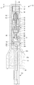
도 2는 도 1의 근접 스위치의 세로 축에 따른 단면도이며; 그리고
도 3은 선택적 플럭스 슬리브와 선택적 대안의 단부 밀봉의 포함을 도시하는 근접 스위치의 세로 축에 따른 단면도이다.1 is an isometric exploded view of a proximity switch in accordance with the principles of the present invention;
Fig. 2 is a cross-sectional view along the longitudinal axis of the proximity switch of Fig. 1; And
3 is a cross-sectional view along the longitudinal axis of a proximity switch showing the inclusion of an optional flux sleeve and an optional alternative end seal.
본 발명의 일부 양상들에 따른 근접 스위치들은 바람직하게, 수중이나 핵 전력 설비들과 같은 가혹한 환경들과 상당한 압력들 하에서, 교체가 필요한 어떠한 사용가능한 부품들도 없이 사용될 수 있는 기밀하게 밀봉된 유닛에 제공된다. 또한, 본 발명의 다른 양상들에 따른 근접 스위치들은 바람직하게 접촉 중단 없이도 10g의 가속도 내진 테스트를 견딜 수 있도록 제 1 및 제 2 위치들 모두에서 접촉 압력을 유지한다. 각 근접 스위치는 바람직하게, 제 1 회로를 완성하는 상시 제 1 위치에 스위치를 유지하기 위한 내부 자기 바이어스를 생성하기 위해 스위치의 표면 가까이에 배치된 자석들의 어레이를 포함하는 스위치 어셈블리를 포함한다. 제 1 회로는 스위치 어셈블리가 어떻게 배선되는지에 따라 상시 개방 또는 상시 폐쇄 회로일 수 있다. 스위치의 표면의 일정한 거리 내로 이동된 철제 금속으로 또는 바람직하게는 자화된 물질로 만들어진 타겟에 의해서와 같이, 내부 자기 바이어스가 차단되거나 또는 과전력되면, 바이어스의 변화는 전기 접촉들의 설정이 타겟이 일정한 거리 이내에 있는 동안은 제 2 회로를 완성하는 제 2 위치로 옮겨지도록 한다. 타겟이 스위치의 표면으로부터 제거되면, 자석들의 어레이는 스위치가 다시 제 1 위치로 옮겨지도록 하고 따라서 스위치는 다시 제 1 회로로 돌아간다. 결과적으로, 각 근접 스위치는 제 1 및 제 2 위치들 사이에서 분명하게 움직이며, 따라서 플러터(flutter)를 최소화하거나 제거한다. 본 기술들의 다른 양상들에 따라 스위치 어셈블리들의 다른 타입들이 사용될 수 있다.Proximity switches according to some aspects of the present invention are preferably used in hermetically sealed units that can be used without any usable parts that need to be replaced under severe conditions such as underwater or nuclear power installations and at considerable pressures / RTI > In addition, the proximity switches according to other aspects of the present invention preferably maintain the contact pressure in both the first and second positions to withstand an acceleration seismic test of 10 g, preferably without contact interruption. Each proximity switch preferably includes a switch assembly including an array of magnets disposed proximate the surface of the switch to produce an internal magnetic bias for maintaining the switch in a normally first position to complete the first circuit. The first circuit may be a normally open or normally closed circuit depending on how the switch assembly is wired. When the internal magnetic bias is interrupted or over-powered, such as by a metallic metal moved within a certain distance of the surface of the switch or preferably made of a magnetized material, the change in bias causes the setting of the electrical contacts to be constant So that the second circuit is moved to the second position where it is within the distance. When the target is removed from the surface of the switch, the array of magnets causes the switch to be moved back to the first position and the switch then returns to the first circuit. As a result, each proximity switch moves clearly between the first and second positions, thus minimizing or eliminating flutter. Other types of switch assemblies may be used in accordance with other aspects of the techniques.
이제 도면들로 돌아가면, 도들 1 및 2는 본 발명의 일반적인 원리들에 따른 한 실시예의 근접 스위치(20)를 도시한다. 근접 스위치(20)는 몸체 튜브(22), 몸체 튜브 내부로 수용되는 스위치 어셈블리(24), 그리고 몸체 튜브 내의 스위치 어셈블리를 기밀하게 밀봉하는 선택적 단부 밀봉 어셈블리(26)를 포함한다. Returning now to the drawings, Figures 1 and 2 illustrate a
몸체 튜브(22)는 폐쇄 단부(30)로부터 개방 단부(32)로 확장하는 블라인드 내부 보어(28)를 갖는 연장된 중공의 튜브형 부재이다. 몸체 튜브(22)와 내부 보어(28)는 바람직하게, 폐쇄 단부로부터 확장하는 제 1 섹션(28a), 제 1 섹션으로부터 확장하는 제 2 섹션(28b), 그리고 제 2 섹션으로부터 개방 단부(32)로 확장하는 제 3 섹션(28c)을 갖는다. 제 1 섹션(28a)은 스위치 어셈블리(24)를 수용할 만한 크기의 제 1 내부 지름을 갖고, 제 2 섹션(28b)은 제 1 지름보다 큰 제 2 내부 지름을 가지며, 제 3 섹션(28c)은 제 2 지름보다 큰 제 3 지름을 갖는다. 제 2 및 제 3 지름들은 이하에서 상세히 설명될 단부 밀봉 어셈블리(26)의 상이한 부분들을 수용할 만한 크기이다. 몸체 튜브(22)의 외부 표면은 바람직하게 나사식 샤프트와 헤드 사이에 중간 부분을 갖는 스터드(stud)의 모양을 가지며, 각각은 섹션들(28a-c) 중 하나에 대응한다. 바람직하게, 제 1 섹션(28a)에 따른 외부 표면은, 예를 들면, 벨브 몸체, 원통 헤드, 또는 당업자에게 명백하게 근접 스위치를 사용하도록 적응되는 임의의 다른 아이템의 보어 내에 나사모양으로 수용되도록 꼬아진다. 제 2 섹션(32b)에 따른 외부 표면은 일반적으로 도면에 도시된 바와 같이 원통형일 수 있으나, 다른 모양을 가질 수도 있다. 제 3 섹션(28c)에 따른 외부 표면은 바람직하게는 표준의 6각 볼트 헤드와 같은, 볼트 헤드의 형태를 가진다. 몸체 튜브(22)는 특별한 사용 환경의 요청들에 따라 상이한 크기들과 치수를 가질 수 있다. 도면들에서 도시된 배열에서, 몸체 튜브는 단부 벽(30)부터 개방 단부(32)까지 4인치의 축 길이를 가지며, 가혹한 동작 환경들을 견디는데 충분한, 스테인레스 스틸과 같은 금속으로 만들어진다.The
스위치 어셈블리(24)는 조립될 때 일반적으로 원통형 외부 폼 팩터를 가지며 내부 보어(28)의 제 1 섹션(28a)에 딱 맞춰진다. 스위치 어셈블리(24)는 원통형 폼 팩터의 제 1 단부에 배치된 1차 자석(34)을 포함한다. 1차 자석(34)은 리테이너(36)에 의해 이송되며, 리테이너는 바람직하게 단부 벽(36b)을 갖는 중공 원통(36a)의 모양이다. 1차 자석(34)은 원통(36a) 내에 수용되며 접착제와 같은 임의의 편리한 잠금 장치에 의해 단부 벽(36b)에 부착된다. 바이어싱 자석(38)은 리테이너(36)에 인접하고 1차 자석(34)의 자속 구역 내에 있는 원통형 케이스(42)의 제 1 단부 내의 제 1 공동(40)에 배치된다. 바이어싱 자석(38)은 원통형 케이스(42)의 단부 벽(44)에 의해 리테이너(36)의 단부 벽으로부터 분리된다. 바람직한 배열에서, 1차 자석(34)과 바이어싱 자석(38)의 각각은 영구 자석들이며 서로 부착되도록 서로 대면하는 반대 극들(즉, 북 대 남)을 갖고, 원통형 케이스(42)는 플라스틱과 같은 전기적 절연 물질로 만들어진다.The
푸시/풀 플런저 어셈블리(46)는 원통형 케이스(42) 내부의 제 2 공동(48)에 미끄러지기 쉽게 배치된다. 원통형 케이스(42)의 분리 벽(50)은 제 2 공동(48)을 제 1 공동(40)으로부터 분리시킨다. 푸시/풀 플런저 어셈블리(46)는 피스톤 헤드 어셈블리(52)와, 분리 벽(50)에 인접한 피스톤 헤드 어셈블리(52)의 제 1 단부로부터 확장하는 축 샤프트(54)를 포함한다. 샤프트(54)는 중심 축 보어(53)를 통해 분리 벽(50), 바이어싱 자석(38), 그리고 단부 벽(44)을 통해 확장하며, 리테이너(36)의 단부 벽(36a)과 연결되어 1차 자석(34)과 피스톤 헤드 어셈블리(52)가 함께 이동하게 된다. 피스톤 헤드 어셈블리(52)는 미끄러짐에 의해서와 같이 제 2 공동(48) 내부에서 축을 따라 옮겨지도록 배열된다. 피스톤 헤드 어셈블리(52)는 플라스틱과 같은, 전기적 절연 물질로 만들어진 원통형 몸체(58) 내에 캡슐화된 제 2 바이어싱 자석(56)을 포함한다. 제 2 바이어싱 자석(56)은 바람직하게 서로 밀어내도록 자기적으로 바이어스되게 하기 위하여 바이어싱 자석(38)의 반대 극을 대면하는 동일한 극을 갖도록(즉, 북-대-북 또는 남-대-남) 배열된다.The push /
전기적으로 전도성인 얇은 조각의 형태인, 예를 들면 구리인 공통 접촉(60)은 나사(62)와 같은 임의의 편리한 수단에 의해 피스톤 헤드 어셈블리(52)의 제 2 단부에 연결되어, 공통 접촉(60)이 피스톤 헤드 어셈블리(52)와 함께 이동하게 한다. 공통 접촉(60)은 일측(도 2의 좌측) 상의 제 1 단부(60a)로부터 반대측(도 2의 우측) 상의 제 2 단부(60b)로 피스톤 헤드 어셈블리(52)의 제 2 단부를 가로질러 측면으로 확장한다. 공통 접촉의 제 1 단부(60a)는 제 1 회로 접촉(64)과 제 2 회로 접촉(66) 사이에서 축을 따라 배치된다. 제 1 회로 접촉(64)은 스위치 어셈블리(24)의 세로 축(68)을 따라 제 2 회로 접촉(66)으로부터 이격되어 위치되며 그 거리는 공통 접촉(60)의 제 1 단부(60a)의 두께와 내부 보어(28) 및 제 2 공동(48) 내의 1차 자석(34) 및 푸시/풀 플런저 어셈블리(46) 각각의 스트로크 길이(S)의 합과 실질적으로 동일하다. 바람직하게, 내부 보어의 제 1 섹션(28a)과 제 2 공동(48)의 각각은 1차 자석(34)과 피스톤 헤드 어셈블리(46)에게 축을 따라 앞뒤로 이동할 수 있는 공간을 허용하는 세로축(68)을 따르는 길이를 가지며, 그 길이는 공통 접촉(60)이 제 1 회로 접촉(64)과의 연결로부터 제 2 회로 접촉(66)과의 연결까지의 거리를 정확히 이동하고, 또한 반대로 이동할 수 있도록 허용하는데 충분한 스트로크 길이(S)와 동일하다.
전기적 절연 물질로 형성된 헤더 어셈블리(70)는 원통형 케이스(42)의 제 2 단부를 밀봉되도록 덮는다. 헤더 어셈블리(70)는 원통형의, 디스크 모양 플러그(72)와, 플러그(72)를 통해 확장하는 전기적 전도성의 제 1, 제 2, 및 제 3 핀들(74, 76, 78)을 포함한다. 플러그(72)는 원통형 케이스(42)의 제 2 단부 내에 수용되는 크기를 가지며 이를 플러그하고, 이는 제 2 부분(28b)에 인접한 몸체 튜브(22)의 내부 보어(28)의 제 1 부분(28a) 내에 위치된다. 따라서, 전체 스위치 어셈블리(24)는 바람직하게 내부 보어(28)의 제 1 부분(28a) 내에 포함된다. 제 1 핀(74)은 제 1 회로 접촉(64)과 전기적으로 연결된다. 제 2 핀(76)은 제 2 회로 접촉(66)과 전기적으로 연결된다. 바람직한 배열에서, 제 1 회로 접촉(64)은 제 1 핀(74)의 말단부이며, 제 2 회로 접촉(66)은 제 2 핀(76)의 말단부이다. 각 핀(74, 76)은 실질적으로 세로축(68)을 따라 축방향으로 정렬된다. 각 핀(74, 76)의 말단부는 세로축(68)으로 직교와 같이 가로로 확장하는 접촉 부분을 형성하도록 구부러지거나 각지며, 앞서 설명된 것과 같이 축을 따라 이격되어 배치된다. 제 3 핀(78)은 피그테일(80, pigtail)과 같은, 유연한 커넥터에 연결되며, 이는 또한 공통 접촉(60)에 연결된다. 핀들(74, 76, 및 78)의 각각의 후단부 또는 전단부는 플러그(72)의 단부 벽을 통해 몸체 튜브(22)의 개방 단부(32)를 향하여 확장한다. 바람직하게, 밀봉 플러그(82)는 플러그(72)를 통해 중심으로 축을 따라 정렬된 보어(84)에 밀봉되도록 배치된다. 일부 응용들에서, 보어(84)를 개방된 채로 놔두도록 밀봉 플러그(82)를 제거하거나 또는 보어(84)를 제거하는 것이 바람직할 수 있다.A header assembly (70) formed of an electrically insulating material covers the second end of the cylindrical case (42) in a sealed manner. The
피그테일(80)은 공통 접촉(60)이 제 1 및 제 2 회로 접촉들(64, 66) 사이에서 축을 따라 앞뒤로 이동하는 것을 허용하기에 충분한 양의 유연한 임의의 전기적 전도성 물질로 만들어질 수 있다. 바람직한 실시예에서, 피그테일은 유연한 와이어 직물로 만들어진다. 다른 가능한 물질들은, 예를 들면, 탄소 섬유 강화 직물들 또는 플라스틱들을 포함할 수 있다. 바람직하게, 필수적이지는 않지만, 피그테일(80)은 제 1 또는 제 2 회로 접촉들(64, 66) 중 하나를 향한 피스톤 헤드 어셈블리(52)의 임의의 기계적 바이어스를 최소화하기에 충분하게 유연하며, 따라서 푸시/풀 플런저 어셈블리(46)의 움직임은 자석들(34, 38, 및 56) 사이의 다양한 자기력들에 의해서만 실질적으로 제어된다.The
동작에서, 자석들(34, 38, 및 56)은 푸시/풀 플런저 어셈블리(46)를 헤더 어셈블리(70)를 향한 상시의 제 1 위치로 바이어스하도록 동작하고, 공통 접촉(60)은 제 1 회로 접촉(64)에 대치하는 접촉으로 바이어스되며 제 2 회로 접촉(66)으로는 접촉하지 않는다. 바람직하게, 자석들(34, 38, 56)은 10 G까지의 내진 가속도 부하동안 공통 접촉(60)과 제 1 회로 접촉(64) 사이의 차단되지 않은 접촉을 유지하도록 선택되고 배열된다. 타겟 자석(도시되지 않음)이 몸체 튜브(22)의 폐쇄 단부(30)의 선택된 최소 거리 내로 이동되면, 타겟 자석은 바이어싱 자석(38, 56)의 바이어싱 힘들을 극복하고 1차 자석(34)을, 그 후 전체 푸시/풀 플런저 어셈블리(46)를 폐쇄 단부(30)를 향한 제 2 위치로 밀어낸다. 제 2 위치에서, 공통 접촉(60)은 제 2 회로 접촉(66)에 대치하는 접촉으로 바이어스되고 제 1 회로 접촉(64)으로는 접촉하지 않는다. 바람직하게, 1차 자석(34)과 바이어싱 자석(38) 사이의 공간은 두개의 자석들 사이에 배치된 단부 벽(44)과 리테이너(36)의 단부 벽만을 갖는 것에 의해 최소화되고, 샤프트(54)의 길이가 따라서 최소화되며, 이는 10 G까지의 내진 가속도에서 제 1 접촉(64)과 차단되지 않게 접촉하는 공통 접촉(60)을 유지하도록 도와주기 위해 자석들(34, 38) 사이에 충분히 강한 자기 인력을 제공한다.In operation, the
바람직한 배열의 단부 밀봉 어셈블리(26)는 습기 및/또는 다른 유해한 물질들이 스위치 어셈블리(24)의 외부에 있도록 몸체 튜브(22)의 개방 단부(32)에 대한 기밀 밀봉을 제공하며, 접촉들(60, 64, 66)에 전기적으로 결합된 또는 연결된 전기 리드 배선들이 전기 리드 배선들의 배선연결 및 다양한 회로들을 따라 다양한 연결들을 절충하는 방식으로 당겨지거나 또는 이동되는 것으로부터의 보호를 제어하기 위한 연결에 액세스되는 것을 허용한다. 단부 밀봉 어셈블리(26)는 기밀 밀봉(90), 중공 크러쉬 링(92), 크러쉬 링 압축 디바이스(94), 페룰(96), 잼 너트(98), 및 포팅(100)을 포함하며, 모두는 바람직하게 내부 보어의 제 2 및 제 3 부분들(28b, 28c)에 배치된다.The
기밀 밀봉(90)은 그를 통해 확장하는 3개의 구멍들을 갖는 원형 디스크(102)와 각 구멍을 통해 배치된 중공 튜브(104)를 포함한다. 각 중공 튜브(104)는 스위치 어셈블리(24)와 대면하는 디스크의 내부측 상에 배치된 제 1 단부(104a)와 개방 단부(32)를 향한 디스크의 외부측 상에 배치된 제 2 단부(104b)를 갖는다. 각 중공 튜브(104)는 마찰 결합으로 핀들(74, 76, 및 78) 중 하나의 전단부를 수용하도록 배열되고 그에 맞는 크기의 내부 지름을 갖는다. 선택적으로, 제 4 중공 튜브(106)가 원형 디스크(102)를 통한 제 4 구멍을 통해 배치되고 다음 밀봉 전 압력 테스트를 수행하기 위해 개방된 채로 남아있을 수 있다. 튜브(106)는 바람직하게 다른 세 개의 튜브들(104)보다 큰 내부 지름을 갖는다. 디스크(102)는 지정된 압력과 다른 조건들을 밀봉상태로 견디는데 충분한 밀봉 링(108)에 의해 내부 보어(28)의 제 2 부분(28b)의 내부 표면에 부착된다. 밀봉 링(108)은 지정된 압력 및/또는 다른 조건들을 견디는데 적절한 땜납 링, 접착제, 용접, 또는 다른 밀봉 물질일 수 있다. 핀들(74,76, 및 78)은 바람직하게 예를 들면, 납땜 또는 용접에 의해 디스크(102)의 내부 측 상의 튜브들(104)의 각각에 부착된다.The
케이블(110)은 3개의 분리된 전기 배선들(110a, 110b, 및 110c)을 포함한다. 각 배선(110a, 110b, 110c)은 예를 들면, 튜브 내에 수용되고 땜납으로 부착되는 단부 핀(111)에 의해 튜브들(104)의 각각으로 연결된다. 케이블(110)은 임의의 충분한 방식으로 접촉들(60, 64, 66), 핀들(74, 76, 및 78), 및 튜브들(104)에 의해 형성된 제 1 및 제 2 회로들을 완성하는 것에 의해 다른 곳의 제어 및/또는 감지 회로들과 연결되도록 배열된다. 본 발명의 목적들을 위해 특히 적절한 것은 케이블(110)이 튜브들(104)로부터 내부 보어(28)의 제 2 및 제 3 부분들(28b, 28c)을 따라 몸체 튜브(22)의 개방 단부(32)로 및 그의 밖으로 확장하는 것이다.The
크러쉬 링 압축 디바이스(94)는 예를 들면, 내부 보어(28)의 제 3 부분(28c)으로 돌려끼우는 것에 의해 내부 보어(28)로 고정시키는 플러그이며, 이는 케이블(110)이 그를 통해 확장하는 중심 개구(112)를 갖는다. 바람직하게, 크러쉬 링 압축 디바이스(94)는 내부 보어(28)의 제 3 부분(28c)의 내부 환형 표면 상에 상보적인 내부 쓰레드들(118)과 맞물리는 외부 쓰레드들(116)을 갖는 원통형 플러그 몸체(114)를 갖는다. 바람직하게는 플러그 몸체(114)보다 작은 지름의 짧은 원통형 섹션의 형태인 니플(120)이 플러그 몸체(114)의 외부측 중심 부분으로부터 개방 단부(32)를 향하여 축을 따라 돌출하며, 이는 외부 쓰레드들을 갖는다. 중심 개구(112)는 바람직하게, 니플(120)의 내부의 짧은 원통형 보어 섹션(122), 바람직하게 원통형 보어 섹션의 내부 단부로부터 플러그 몸체(114)의 내부 단부로 확장하는 내부 원뿔형 보어 섹션의 형태인 내부의 테이퍼링된 부분(124), 그리고 바람직하게 원통형 보어 섹션의 외부 단부로부터 니플(120)의 외부 단부로 확장하는 외부 원뿔형 보어 섹션의 형태인 외부의 테이퍼링된 부분(126)을 규정한다.The crush
크러쉬 링(92)은 크러쉬 링 압축 디바이스(94)의 내부 단부와 몸체 튜브(22)의 방사상으로 돌출한 내부의 환형 렛지(128) 사이에서 내부 보어(28)의 제 2 부분(28b)과 제 3 부분(28c)을 연결시키는 개스킷 밀봉으로 작용한다. 크러쉬 링(92)은 근접 스위치(20)의 의도된 사용 환경에 적절한 밀봉 물질로 만들어지며, 한 실시예에서는 가혹한, 고온, 및/또는 핵 환경들에서 사용하기 위하여, 원형 세로 축을 갖는 중공 튜브의 형태를 갖는 중공 스테인레스 스틸 링으로 형성된다. 크러쉬 링(92)은 바람직하게 내부 보어(28)의 제 3 부분(28c)의 내부 지름과 실질적으로 동일한 외부 지름을 갖는다.The
포팅(100)은 크러쉬 링 압축 디바이스(94)와 기밀 밀봉(90) 사이의 공간을 완전히 채운다. 바람직하게, 포팅(100)은 또한 기밀 밀봉(90)과 헤더 어셈블리(70)의 플러그(72)의 단부 벽 사이의 임의의 공간으로 예를 들면, 튜브(106)를 통해 흘러들어가는 것에 의해 스며들어가 채운다. 포팅(100)은 바람직하게 적어도 액체들과 유해한 미립자들이 스위치 어셈블리(24)로 들어가는 것을 방지하기 위하여 내부 보어(28)에 방수성의 기밀 밀봉을 형성하도록 모든 공간들과 틈들로 흘러갈 수 있고 및/또는 압축될 수 있는 밀봉 물질로 형성된다. 바람직한 배열에서, 포팅(100)은 나중에 단단한 덩어리로 굳거나 경화되는 에폭시와 같은 액상 수지 또는 유사한 액상 물질이다.The potting (100) completely fills the space between the crush ring compression device (94) and the hermetic seal (90). The potting 100 preferably also seeps into any space between the
조립의 바람직한 방법에서, 위에서 설명된 것과 같이 스위치 어셈블리(24)와 기밀 밀봉(90)이 설치된 후 개방 단부(32)를 통해 내부 보어(28)에 유체 상태로 포팅(100)이 삽입된다. 바람직하게, 내부 보어(28)는 크러쉬 링 압축 디바이스(94)와 기밀 밀봉(90) 사이의 모든 공간을 완전히 채우기 위해 충분한 포팅(100)으로 채워진다. 한 방법에서, 크러쉬 링(92)이 내부 보어(28)로 삽입된 후 개방 단부(32)로부터 가장 먼 쓰레드(118)로 포팅이 채워지고, 쓰레드들(116 및 118) 사이 및 케이블(110)과 중앙 개구(112) 사이와 같은 크러쉬 링 압축 디바이스(94) 주위의 임의의 틈들과 개구들을 밀봉상태로 채우기 위하여 크러쉬 링 압축 디바이스(94)가 포팅(100)을 압축한다. 바람직하게 포팅(100)은 이후 크러쉬 링 압축 디바이스와 기밀 밀봉(90) 사이의 몸체 튜브(22)의 개방 단부(32)에 고체인 단단한 밀봉 또는 플러그를 형성하도록 굳어지거나 또는 경화된다.In a preferred method of assembly, the porting 100 is inserted into the
페룰(96)은 케이블(110) 주위에 딱 맞추어 외부의 테이퍼링된 보어 섹션(126)으로 끼워 넣는 연장된 튜브형 부재이다. 바람직한 배열에서, 페룰(96)은 폴리에테르에테르케톤(PEEK)으로 만들어지며 원통형 몸체(132), 원통형 몸체(132)의 한 축 방향 단부에 방사상으로 내부를 향해 테이퍼링된 노즈(134), 원통형 몸체(132)의 반대 축 방향 단부에 방사상으로 내부를 향해 테이퍼링된 환형 숄더(136), 및 반대 축 방향 단부들을 통해 확장하는 축 방향 관통 보어(138)를 갖는 총알 모양이다.The
잼 너트(98)는 외부로 테이퍼링된 보어 섹션(126)으로 끼워 넣어진 고정 위치에서 페룰(96)을 품는다. 잼 너트(98)는 바람직하게 원통형 튜브의 반대 축 방향 단부들에 고정 플랜지들(144, 146)을 갖는 원통형 튜브(142)로 형성된다. 각 고정 플랜지(144, 146)는 원통형 튜브(142)의 각각의 축 방향 단부로부터 내부를 향해 방사상으로 돌출한다. 고정 플랜지(144)는 외부의 쓰레드들을 니플(120) 상에 맞물리게 하는 내부의 환형 쓰레드들을 포함하며, 고정 플랜지(146)는 페룰(96)의 환형 숄더(136)를 맞물릴 수 있는 크기이다. 잼 너트(140)는 페룰(96)과 그 주위에 딱 맞으며, 고정 플랜지(144)가 니플(120) 상으로 돌려 끼워짐에 따라 고정 플랜지(146)가 환형 숄더(136)에 압력을 가해서 페룰(96)이 외부의 테이퍼링된 보어 섹션(126)에 대하여 끼워진 맞물림부가 되도록 압박한다. 동시에, 외부의 테이퍼링된 보어 섹션(126)으로부터 페룰(96) 상의 방사상으로 내부를 향해 끼워 넣는 힘이 또한 케이블(110) 주위의 페룰(96)을 조여서 케이블(110) 주위에 밀봉을 또한 형성하게 된다. 페룰(96)과 잼 너트(98)는 또한 근접 스위치(20) 외부의 케이블로 인가된 움직임 또는 힘들이 전기 회로들의 완전성을 손상시킬 수 있는, 포팅(100)으로 옮겨가거나 또는 예를 들면 튜브들(104)의 스위치 어셈블리(24)와의 다양한 전기적 연결들로 옮겨가는 것을 방지하도록 케이블(110)을 중앙 개구(112) 내의 고정 위치로 고정시키는 어셈블리로서 함께 동작한다.The
바람직한 배열에서, 원통형 케이스(42)는 스위치 어셈블리(24)의 조립동안 플런저 어셈블리(46)와 헤더(70)의 시각적 검사를 허용하도록 배열된 케이스의 측벽을 통하여, 윈도우들(150)과 같은 하나 또는 그 이상의 개구들을 가지며, 바람직하게는 두개의 반대방향의 윈도우들(150)을 갖는다. 절연 슬리브(152)는 윈도우들(150)을 덮고 접촉들(60, 64, 66)과 몸체 튜브(22) 사이의 전기적 아킹을 감소시키거나 방지하기 위하여 원통형 하우징(42)의 외부 주위를 꼭 맞춘다. 절연 슬리브는 바람직하게는 E.I. du Pont de Nemours and Company에 의한 Kapton® 필름과 같은 전기적 절연 물질 또는 유사한 물질들로 만들어지며, 조립에 도움을 주기 위한 세로 슬릿(154)을 갖는다. 원통형 케이스(42)에 잘 맞춰진 후에, 슬릿(154)을 통해 확장하는 슬리브의 반대편 에지들은 바람직하게 접착 패치(156)에 의해 함께 연결되는데, 이들은 또한 바람직하게 E.I. du Pont de Nemours and Company에 의한 Kapton® 테이프와 같은 절연 물질 또는 유사한 물질들로 만들어진다.In a preferred arrangement, the
이제 도 3으로 돌아가면, 1차 자석(34)과 원통형 슬리브(42)의 단부 벽(44) 사이에 배치된, 바람직하게는 중공 금속 원통 형태인, 선택적 플럭스 슬리브(160)가 부가된 근접 스위치(20)가 도시된다. 플럭스 슬리브(160)는 바람직하게는 철제 물질로 만들어지며, 자석들 사이의 자기 인력을 감소시키도록 바이어싱 자석(38)으로부터 1차 자석(34)을 분리시키고 자석들의 자속장에 집중한다. 플럭스 슬리브(160)는 바람직하게 단부 벽(44)으로부터 1차 자석(34)을 향해 확장하는 나사식 스터드(162)로 나사식 연결에 의해 원통형 슬리브(42)에 부착된다. 플럭스 슬리브(160)는 나사식 스터드(162)에 돌려 끼워질 수 있다. 1차 자석(34)과 바이어싱 자석(38) 사이의 인력은 플럭스 슬리브(160)의 축의 길이 및/또는 플럭스 슬리브의 물질 및/또는 스터드(162)의 길이를 변화시키는 것에 의해 힘들의 범위 내에서 조절될 수 있다. 또한, 도 3의 근접 스위치(20)의 피스톤 로드(54)는 플럭스 슬리브(160)를 위해 필요한 부가 공간을 수용하기 위해 도 1 및 도 2의 근접 스위치(20)의 피스톤 로드(54)보다 길다. 도 3의 근접 스위치(20)는 또한 단부 밀봉 어셈블리(26)를 포함하지 않는 선택을 갖는 것으로 도시된다. 대신 헤더 어셈블리(70)와 전기 케이블(110)이 포팅(100) 또는 에폭시 수지나 플라스틱과 같은 다른 밀봉 물질만으로 몸체 튜브(22)의 개방 단부(32)에 캡슐화된다. 몸체 튜브(22)는 또한 선택적 외부 쓰레드들과 내부 보어(28)의 테이퍼링된 또는 원뿔형의 제 2 부분(28b)을 갖지 않는 것으로 도시된다. 도 3에 도시된 근접 스위치의 다른 부분들은 대체로 도 1 및 도 2와 관련하여 이전에 도시되고 설명되었으므로, 그의 설명은 여기서 반복되지 않는다.Turning now to FIG. 3, a proximity switch (not shown) with an
여기서 개시된 근접 스위치들(20)은 몸체 튜브(22)가 공통의 테이퍼링된 원통형 보어에 돌려 끼워지는 것을 쉽게 허용하도록 일반적으로 볼트와 같은 모양이며 일반적으로 원형의 원통형 외형의 폼 팩터들을 갖지만, 근접 스위치들(20)은 원형의 원통형으로 제한되지 않는다. 그보다는, 근접 스위치들(20)의 구성성분들은 여기서 설명한 바와 같이 1차 자석(34)과 푸시/풀 플런저 어셈블리(46)가 공통 접촉(60)을 제 1 접촉(64)으로부터 제 2 접촉(66)까지 이동시키고 그 반대로도 이동시키도록 철제 또는 자기 타겟으로 및 그로부터 축을 따라 이동할 수 있는 한 대부분 임의의 단면 모양을 가질 수 있다.The proximity switches 20 disclosed herein are generally bolt-like shaped and have generally circular cylindrical shaped form factors to readily allow the
(산업상 이용 가능성)(Industrial applicability)
여기서 개시된 근접 스위치들은 산업 프로세스 제어 시스템들에서 유용하며, 핵 응용들, 수중, 및 다른 부식성 및/또는 가혹한 동작 환경들에서 사용하기 위한 일부 배열들에서 특히 잘 적응된다. 여기서 개시된 근접 스위치들에 대한 다양한 변경들이 앞의 설명의 관점에서 당업자에게 명백할 것이다. 따라서, 본 설명은 단지 예시적인 것으로 이해되며 당업자가 근접 스위치들을 만들고 이용할 수 있게 하며 동일한 내용을 수행하는 최적의 모드를 제시할 수 있도록 하는 목적을 위해 제공된다. 임의의 청구항들의 범주 내에 속하는 모든 변경들에 대한 배타적 권리들이 보유된다. 앞에서 확인된 모든 특허들, 특허 출원들, 및 다른 인쇄된 출판물들은 그들의 전체들이 본 문서에 참조로 포함된다.The proximity switches disclosed herein are useful in industrial process control systems and are particularly well adapted in some arrangements for use in nuclear applications, underwater, and other corrosive and / or harsh operating environments. Various modifications to the proximity switches disclosed herein will be apparent to those skilled in the art in view of the foregoing description. Accordingly, the description is to be understood as exemplary only, and is provided for the purpose of enabling those skilled in the art to make and use proximity switches and to suggest the optimum mode of performing the same. Exclusive rights to all modifications falling within the scope of any claim are retained. All patents, patent applications, and other printed publications identified above are incorporated herein by reference in their entirety.
Claims (22)
블라인드 보어, 폐쇄 단부, 및 개방 단부를 갖는 몸체 튜브와;
상기 블라인드 보어 내부에 배치된 자기 근접 스위치 어셈블리와;
상기 자기 근접 스위치 어셈블리와 상기 개방 단부 사이의 상기 블라인드 보어를 덮는 기밀 밀봉과;
상기 기밀 밀봉과 상기 개방 단부 사이의 상기 블라인드 보어의 표면에서 규정된 환형 숄더에 대치하여 배치된 크러쉬 링(crush ring)과;
상기 블라인드 보어의 상기 개방 단부로 돌려끼워서 상기 크러쉬 링을 밀봉하도록 맞물리는 나사식 플러그 몸체를 갖는 크러쉬 링 압축 디바이스와;
상기 크러쉬 링 압축 디바이스와 상기 기밀 밀봉 사이의 임의의 공간을 채우는 포팅을 포함하며;
상기 기밀 밀봉, 상기 포팅, 및 상기 크러쉬 링 압축 디바이스는 가압 및 잠수 테스트동안 상기 블라인드 보어를 밀봉하고 상기 자기 근접 스위치를 보호하는, 근접 스위치.For a proximity switch:
A body tube having a blind bore, a closed end, and an open end;
A self proximity switch assembly disposed within the blind bore;
A hermetic seal covering the blind bore between the magnetic proximity switch assembly and the open end;
A crush ring disposed opposite the annular shoulder defined at the surface of the blind bore between the hermetic seal and the open end;
A crush ring compression device having a threaded plug body which is pivotally connected to said open end of said blind bore to engage said crush ring to seal;
And potting to fill any space between the crush ring compression device and the hermetic seal;
Wherein the hermetic seal, the potting, and the crush ring compression device seal the blind bore during a pressurization and diving test and protect the self proximity switch.
개방 단부를 갖는 제 1 보어를 갖는 몸체 튜브와;
상기 보어 내부에 배치된 근접 스위치 어셈블리와;
상기 개방 단부의 내부에 딱 맞아서 상기 보어의 환형 벽에 대해 고정되는 몸체를 갖는 플러그로서, 상기 몸체는 그를 통과하는 제 2 보어를 갖는, 상기 플러그와;
상기 근접 스위치 어셈블리와 전기적으로 결합되고 상기 제 2 보어를 통해 연장하는 전기 리드와;
상기 전기 리드를 둘러싸며 상기 제 2 보어의 내부에 배치된 페룰과;
상기 플러그와 결합되어 상기 페룰을 상기 제 2 보어와 밀봉 접촉으로 압박하고 상기 제 2 보어 내의 고정 위치에 상기 전기 리드를 고정시키는 잼 너트를 포함하는, 근접 스위치.For a proximity switch:
A body tube having a first bore with an open end;
A proximity switch assembly disposed within the bore;
A plug having a body that fits within the open end and is secured to an annular wall of the bore, the body having a second bore therethrough;
An electrical lead electrically coupled to the proximity switch assembly and extending through the second bore;
A ferrule surrounding the electrical lead and disposed within the second bore;
And a jam nut coupled with the plug to press the ferrule in sealing contact with the second bore and to secure the electrical lead in a fixed position within the second bore.
1차 자석과;
상기 1차 자석으로부터 이격된 피스톤 헤드와 상기 피스톤 헤드와 상기 1차 자석을 연결하는 피스톤 로드를 포함하는 플런저와;
상기 피스톤 헤드에 의해 이송되어 상기 피스톤 헤드의 움직임으로 전기 회로를 개방 및/또는 폐쇄하도록 배열된 전기 접촉과;
상기 1차 스위치와 상기 피스톤 헤드 사이의 상기 피스톤 로드에 인접하게 위치된 바이어싱 자석을 포함하며;
상기 바이어싱 자석은 상기 바이어싱 자석을 향하여 또는 그로부터 멀리 상기 피스톤 로드를 따라 축 방향으로 상기 1차 자석을 바이어스하도록 배열되고, 상기 플런저와 상기 1차 자석은 상기 바이어싱 자석에 대하여 축을 따라 이동하도록 배열되며, 상기 1 차 자석과 상기 바이어싱 자석 사이에는 플럭스 슬리브가 배치되지 않는, 근접 스위치 어셈블리.A proximity switch assembly comprising:
A primary magnet;
A plunger including a piston head spaced from the primary magnet, and a piston rod connecting the piston head and the primary magnet;
An electrical contact arranged to open and / or close the electrical circuit by movement of the piston head carried by the piston head;
A biasing magnet positioned adjacent the piston rod between the primary switch and the piston head;
Wherein the biasing magnet is arranged to bias the primary magnet axially along the piston rod toward or away from the biasing magnet and the plunger and the primary magnet move along an axis with respect to the biasing magnet And wherein a flux sleeve is not disposed between the primary magnet and the biasing magnet.
Applications Claiming Priority (3)
| Application Number | Priority Date | Filing Date | Title |
|---|---|---|---|
| US201161580833P | 2011-12-28 | 2011-12-28 | |
| US61/580,833 | 2011-12-28 | ||
| PCT/US2012/070798 WO2013101628A1 (en) | 2011-12-28 | 2012-12-20 | Proximity switch |
Publications (2)
| Publication Number | Publication Date |
|---|---|
| KR20140119002A true KR20140119002A (en) | 2014-10-08 |
| KR102049128B1 KR102049128B1 (en) | 2019-11-26 |
Family
ID=47604104
Family Applications (1)
| Application Number | Title | Priority Date | Filing Date |
|---|---|---|---|
| KR1020147017750A KR102049128B1 (en) | 2011-12-28 | 2012-12-20 | Proximity switch |
Country Status (11)
| Country | Link |
|---|---|
| US (1) | US8766751B2 (en) |
| EP (2) | EP2798652B1 (en) |
| JP (1) | JP2015506555A (en) |
| KR (1) | KR102049128B1 (en) |
| CN (2) | CN103187203B (en) |
| AR (1) | AR089436A1 (en) |
| BR (1) | BR112014015829A8 (en) |
| CA (1) | CA2859538A1 (en) |
| MX (1) | MX2014008012A (en) |
| RU (1) | RU2014130181A (en) |
| WO (1) | WO2013101628A1 (en) |
Families Citing this family (12)
| Publication number | Priority date | Publication date | Assignee | Title |
|---|---|---|---|---|
| CN103295836B (en) * | 2011-12-28 | 2017-10-31 | 通用设备和制造公司 | Double-pole double-throw proximity switch |
| CN103187203B (en) * | 2011-12-28 | 2017-12-08 | 通用设备和制造公司 | Proximity switch |
| CN104344065B (en) | 2013-08-01 | 2019-07-23 | 通用设备和制造公司 | A kind of configurable switch emulator module |
| US10298229B2 (en) | 2017-01-05 | 2019-05-21 | General Equipment And Manufacturing Company, Inc. | Switch adapter |
| US10935151B2 (en) * | 2017-08-29 | 2021-03-02 | Tlx Technologies, Llc. | Solenoid actuator with firing pin position detection |
| DE102018121850B4 (en) | 2018-09-07 | 2020-08-20 | Kraussmaffei Technologies Gmbh | Sensor arrangement with a plug protection device |
| CN111785541B (en) * | 2019-04-03 | 2022-08-30 | 上海汽车集团股份有限公司 | Switch for controlling on-off of power battery loop |
| DE102019112581B4 (en) * | 2019-05-14 | 2020-12-17 | Marcel P. HOFSAESS | Temperature dependent switch |
| US11456134B2 (en) * | 2020-01-09 | 2022-09-27 | General Equipment And Manufacturing Company, Inc. | Magnetic reed switch assembly and method |
| CN111555747A (en) * | 2020-04-07 | 2020-08-18 | 武汉船用机械有限责任公司 | Proximity switch |
| WO2022171975A1 (en) | 2021-02-09 | 2022-08-18 | Longvale Ltd | Sensor assemblies |
| GB2588568B (en) | 2021-02-09 | 2021-11-03 | Longvale Ltd | Sensor assemblies |
Citations (1)
| Publication number | Priority date | Publication date | Assignee | Title |
|---|---|---|---|---|
| US6299426B1 (en) * | 1999-06-25 | 2001-10-09 | Pfa Incorporated | Mold and die casting apparatus including a compact core position sensor unit having magnetic switches |
Family Cites Families (17)
| Publication number | Priority date | Publication date | Assignee | Title |
|---|---|---|---|---|
| US3219811A (en) * | 1963-02-05 | 1965-11-23 | Clyde S Young | Watertight flashlight with magnetic switch |
| GB1217677A (en) | 1967-02-17 | 1970-12-31 | Btr Industries Ltd | A pressure indicating device |
| US4117431A (en) * | 1977-06-13 | 1978-09-26 | General Equipment & Manufacturing Co., Inc. | Magnetic proximity device |
| JPS57143624U (en) * | 1981-03-05 | 1982-09-09 | ||
| GB8715089D0 (en) * | 1987-06-26 | 1987-08-05 | Birns Uk Ltd | Electrical switches |
| US4788517A (en) | 1987-10-08 | 1988-11-29 | Beta Mfg. Co. | Sealed proximity switch assembly |
| US4837539A (en) * | 1987-12-08 | 1989-06-06 | Cameron Iron Works Usa, Inc. | Magnetic sensing proximity detector |
| US5808255A (en) * | 1996-07-22 | 1998-09-15 | Texas Instruments Incorporated | Fluid pressure responsive electric switch |
| US5798910A (en) * | 1996-08-29 | 1998-08-25 | Caloritech Inc. | Sealable housing for electrical components |
| US6127910A (en) * | 1998-06-05 | 2000-10-03 | Topworx, Inc. | Hermetically sealed proximity switch |
| DE10104083C2 (en) * | 2000-01-28 | 2002-07-11 | Ifm Electronic Gmbh | Assembly from a proximity switch and a cable connection part and method for their production |
| US6857902B2 (en) * | 2001-02-21 | 2005-02-22 | I F M Electronics Gmbh | Proximity switch and a cable terminal part unit and a process for its manufacture |
| DE10237904B4 (en) | 2002-06-14 | 2007-05-31 | Ifm Electronic Gmbh | Electronic sensor and assembly of an electronic sensor and a fastener |
| US7489217B2 (en) * | 2007-04-24 | 2009-02-10 | Rohrig Iii Vincent W | Magnetic proximity sensor |
| WO2009003016A1 (en) * | 2007-06-26 | 2008-12-31 | Swagelok Company | Conduit connection with sensing function |
| BR112012031151B1 (en) * | 2010-06-11 | 2020-01-14 | General Equipment And Mfg Company Inc D/B/A Topworx Inc | magnetically triggered proximity switch |
| CN103187203B (en) * | 2011-12-28 | 2017-12-08 | 通用设备和制造公司 | Proximity switch |
-
2012
- 2012-12-19 CN CN201210599041.8A patent/CN103187203B/en active Active
- 2012-12-19 CN CN2012207570267U patent/CN203312156U/en not_active Withdrawn - After Issue
- 2012-12-20 CA CA2859538A patent/CA2859538A1/en not_active Abandoned
- 2012-12-20 MX MX2014008012A patent/MX2014008012A/en active IP Right Grant
- 2012-12-20 EP EP12818730.9A patent/EP2798652B1/en active Active
- 2012-12-20 RU RU2014130181A patent/RU2014130181A/en not_active Application Discontinuation
- 2012-12-20 JP JP2014550365A patent/JP2015506555A/en active Pending
- 2012-12-20 KR KR1020147017750A patent/KR102049128B1/en active IP Right Grant
- 2012-12-20 EP EP15156180.0A patent/EP2905798B1/en active Active
- 2012-12-20 WO PCT/US2012/070798 patent/WO2013101628A1/en active Application Filing
- 2012-12-20 BR BR112014015829A patent/BR112014015829A8/en not_active IP Right Cessation
- 2012-12-21 AR ARP120104945A patent/AR089436A1/en unknown
- 2012-12-27 US US13/728,398 patent/US8766751B2/en active Active
Patent Citations (1)
| Publication number | Priority date | Publication date | Assignee | Title |
|---|---|---|---|---|
| US6299426B1 (en) * | 1999-06-25 | 2001-10-09 | Pfa Incorporated | Mold and die casting apparatus including a compact core position sensor unit having magnetic switches |
Also Published As
| Publication number | Publication date |
|---|---|
| AR089436A1 (en) | 2014-08-20 |
| EP2905798A1 (en) | 2015-08-12 |
| CN203312156U (en) | 2013-11-27 |
| EP2905798B1 (en) | 2016-09-21 |
| BR112014015829A8 (en) | 2017-07-04 |
| US20130169388A1 (en) | 2013-07-04 |
| CA2859538A1 (en) | 2013-07-04 |
| JP2015506555A (en) | 2015-03-02 |
| US8766751B2 (en) | 2014-07-01 |
| WO2013101628A1 (en) | 2013-07-04 |
| CN103187203B (en) | 2017-12-08 |
| CN103187203A (en) | 2013-07-03 |
| KR102049128B1 (en) | 2019-11-26 |
| EP2798652A1 (en) | 2014-11-05 |
| RU2014130181A (en) | 2016-02-20 |
| EP2798652B1 (en) | 2016-04-13 |
| BR112014015829A2 (en) | 2017-06-13 |
| MX2014008012A (en) | 2014-08-21 |
Similar Documents
| Publication | Publication Date | Title |
|---|---|---|
| KR102049128B1 (en) | Proximity switch | |
| US10020147B2 (en) | Double pole-double throw proximity switch | |
| US7855551B2 (en) | Stick position sensor with removable cover for a sensor head | |
| KR101809216B1 (en) | Quick disconnect connector assembly | |
| GB2588568A (en) | Sensor assemblies | |
| US10003333B2 (en) | Method of manufacturing an enclosed proximity switch assembly | |
| RU2460006C1 (en) | Chip detector | |
| US20030234165A1 (en) | Electrical switches and methods of establishing an electrical connection | |
| US11174976B2 (en) | Magnetic patch system | |
| CN107990039B (en) | Electromagnetic valve pilot device and intrinsic safety explosion-proof electromagnetic valve with same | |
| RU2381583C1 (en) | Electromagnet for operation in product in conditions of increased pressure of environment | |
| WO2022171975A1 (en) | Sensor assemblies | |
| JPWO2020045327A1 (en) | Stroke sensor |
Legal Events
| Date | Code | Title | Description |
|---|---|---|---|
| A201 | Request for examination | ||
| E902 | Notification of reason for refusal | ||
| E701 | Decision to grant or registration of patent right | ||
| GRNT | Written decision to grant |