KR20140114905A - Device for reversing the movement and/or actuation direction of an actuating cable of a mechanism - Google Patents
Device for reversing the movement and/or actuation direction of an actuating cable of a mechanism Download PDFInfo
- Publication number
- KR20140114905A KR20140114905A KR1020147025009A KR20147025009A KR20140114905A KR 20140114905 A KR20140114905 A KR 20140114905A KR 1020147025009 A KR1020147025009 A KR 1020147025009A KR 20147025009 A KR20147025009 A KR 20147025009A KR 20140114905 A KR20140114905 A KR 20140114905A
- Authority
- KR
- South Korea
- Prior art keywords
- drive
- movement
- cable
- housing
- reversing
- Prior art date
Links
Images


Classifications
-
- F—MECHANICAL ENGINEERING; LIGHTING; HEATING; WEAPONS; BLASTING
- F16—ENGINEERING ELEMENTS AND UNITS; GENERAL MEASURES FOR PRODUCING AND MAINTAINING EFFECTIVE FUNCTIONING OF MACHINES OR INSTALLATIONS; THERMAL INSULATION IN GENERAL
- F16C—SHAFTS; FLEXIBLE SHAFTS; ELEMENTS OR CRANKSHAFT MECHANISMS; ROTARY BODIES OTHER THAN GEARING ELEMENTS; BEARINGS
- F16C1/00—Flexible shafts; Mechanical means for transmitting movement in a flexible sheathing
- F16C1/10—Means for transmitting linear movement in a flexible sheathing, e.g. "Bowden-mechanisms"
- F16C1/12—Arrangements for transmitting movement to or from the flexible member
- F16C1/14—Construction of the end-piece of the flexible member; Attachment thereof to the flexible member
- F16C1/145—Attachment of the end-piece to the flexible member
-
- Y—GENERAL TAGGING OF NEW TECHNOLOGICAL DEVELOPMENTS; GENERAL TAGGING OF CROSS-SECTIONAL TECHNOLOGIES SPANNING OVER SEVERAL SECTIONS OF THE IPC; TECHNICAL SUBJECTS COVERED BY FORMER USPC CROSS-REFERENCE ART COLLECTIONS [XRACs] AND DIGESTS
- Y10—TECHNICAL SUBJECTS COVERED BY FORMER USPC
- Y10T—TECHNICAL SUBJECTS COVERED BY FORMER US CLASSIFICATION
- Y10T74/00—Machine element or mechanism
- Y10T74/11—Tripping mechanism
-
- Y—GENERAL TAGGING OF NEW TECHNOLOGICAL DEVELOPMENTS; GENERAL TAGGING OF CROSS-SECTIONAL TECHNOLOGIES SPANNING OVER SEVERAL SECTIONS OF THE IPC; TECHNICAL SUBJECTS COVERED BY FORMER USPC CROSS-REFERENCE ART COLLECTIONS [XRACs] AND DIGESTS
- Y10—TECHNICAL SUBJECTS COVERED BY FORMER USPC
- Y10T—TECHNICAL SUBJECTS COVERED BY FORMER US CLASSIFICATION
- Y10T74/00—Machine element or mechanism
- Y10T74/20—Control lever and linkage systems
- Y10T74/20396—Hand operated
- Y10T74/20402—Flexible transmitter [e.g., Bowden cable]
- Y10T74/20462—Specific cable connector or guide
Abstract
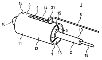
본 발명은 메커니즘의 구동 케이블(2)의 운동 및/또는 구동 방향의 역전을 위한 장치(1)에 관한 것이다. 본 발명에 따르면, 슬라이딩 피스톤(5)이 프레임에 고정되는 하우징(3) 내에 슬라이딩 방식으로 변위 가능하도록 배열되고, 슬라이딩 피스톤은 구동 케이블(2)에 의해 변위될 수 있다. 하나 이상의 구동 요소(6)가 슬라이딩 피스톤(5) 상에 측방향으로 배열되며, 상기 구동 요소의 운동 방향은 구동 케이블(2)의 운동 방향에 대향하고 상기 구동 요소는 메커니즘에 기계적으로 커플링된다(도 1). The present invention relates to an apparatus (1) for the movement of a drive cable (2) of a mechanism and / or a reversal of the drive direction. According to the present invention, the sliding piston 5 is arranged so as to be displaceable in a sliding manner in the housing 3 fixed to the frame, and the sliding piston can be displaced by the driving cable 2. One or more drive elements 6 are laterally arranged on the sliding piston 5 and the direction of motion of the drive element is opposite to the direction of motion of the drive cable 2 and the drive element is mechanically coupled to the mechanism (Fig. 1).
Description
본 발명은 청구항 제 1 항의 전제부에 따른 메커니즘의 구동 케이블의 운동 및/또는 구동 방향의 역전 장치에 관한 것이다.
The present invention relates to a mechanism for reversing the movement and / or the drive direction of a drive cable of a mechanism according to the preamble of
종래 기술에서, 차량 내에 떨어져서 배열된 메커니즘들을 위한 구동 케이블들은 운동 및/또는 구동 방향의 역전이 필수적이지 않은 방식으로 배열되거나 놓인다. 몇몇 상황들 하에서, 이는 구동 케이블이 큰 아치형으로 놓이는 것을 요구하고, 그 결과 구동 케이블의 구조 공간 및 길이에 대한 요구 사항이 증가한다.
In the prior art, the drive cables for the mechanisms arranged in the vehicle apart are arranged or laid in such a way that the inversion of the movement and / or drive direction is not necessary. Under some circumstances, this requires the drive cable to be placed in a large arcuate form, which results in increased requirements for the structural space and length of the drive cable.
FR 2 765 926 A1 호는 메커니즘의 구동 케이블의 운동 및/또는 구동 방향의 역전 장치를 기재한다.
GB 166 655 A 호는 함께 구동 가능한 또는 서로 독립적으로 구동 가능한 복수의 구동 케이블들을 구비한 장치를 기재한다.
GB 166 655 A describes an apparatus with a plurality of drive cables which can be driven together or independently of each other.
US 4 526 057 A 호는 구동 케이블에 의해 2 개의 커플링된 메커니즘들을 구동하는 장치를 기재한다.
US 4 526 057 A describes a device for driving two coupled mechanisms by means of a drive cable.
본 발명의 목적은 메커니즘의 구동 케이블의 운동 및/또는 구동 방향의 역전 장치를 명시하는 것이며, 이 장치는 종래 기술에 대하여 개선된다.
It is an object of the present invention to specify a reversing device for the movement and / or driving direction of a drive cable of a mechanism, which device is improved over the prior art.
메커니즘의 구동 케이블의 운동 및/또는 구동 방향의 역전 장치에 대하여, 이 목적은 청구항 제 1 항에 명시된 특징들에 의해 달성된다.
This object is achieved by the features specified in
본 발명의 유리한 개량들은 종속 청구항들의 요지이다.
Advantageous refinements of the invention are the subject matter of the dependent claims.
메커니즘의 구동 케이블의 운동 및/또는 구동 방향의 역전 장치의 경우에, 본 발명에 따르면 슬라이딩 피스톤이 프레임 상에 고정되어 배열되는 하우징 내에서 슬라이딩 방식으로 변위 가능하도록 배열되고, 구동 케이블에 의해 변위될 수 있으며, 하나 이상의 구동 요소가 슬라이딩 피스톤 상에 측방향으로 배열되고, 이 구동 요소의 운동 방향은 구동 케이블의 구동 방향에 대향하고 구동 요소는 메커니즘에 기계적으로 커플링된다. 그 결과, 구동 케이블의 운동 및/또는 구동 방향의 역전은 구조 공간을 간단한 방식으로 절약하는 것을 가능하게 한다.
According to the present invention, in the case of the mechanism for reversing the movement and / or the driving direction of the driving cable of the mechanism, the sliding piston is arranged to be displaceable in a sliding manner in a housing fixedly arranged on the frame, And at least one driving element is arranged laterally on the sliding piston, the driving direction of which is opposite to the driving direction of the driving cable and the driving element is mechanically coupled to the mechanism. As a result, the movement of the drive cable and / or the inversion of the drive direction makes it possible to save the structural space in a simple manner.
유리한 실시예에서, 복수의 구동 요소들이 슬라이딩 피스톤 상에 배열되고, 그 결과 복수의 구동 요소들은 개별 구동 케이블에 의해 간단한 방식으로 구동 가능하다.
In an advantageous embodiment, a plurality of driving elements are arranged on the sliding piston, so that the plurality of driving elements can be driven in a simple manner by separate driving cables.
여기서 각각의 구동 요소의 운동 방향은 구동 케이블의 운동 방향과 동일한 방향으로 또는 대향 방향으로 형성될 수 있다.
Here, the direction of motion of each driving element may be formed in the same direction as the direction of motion of the driving cable or in the opposite direction.
하우징은 편의적으로는 원통형으로 또는 컵 형상의 방식으로 형성되고 개방 제 1 단부 및 폐쇄 제 2 단부를 갖는다.
The housing is conveniently formed in a cylindrical or cup-shaped manner and has an open first end and a closed second end.
특히 유리한 실시예에서, 폐쇄 단부의 하우징의 외측 상에, 하나 이상의 체결 섹션이 단부 측 및/또는 외부 둘레 상에 배열된다. 이러한 체결 섹션에 의해, 하우징은 프레임 상에 또는 예컨대 차량 내에 고정되어 배열될 수 있다.
In a particularly advantageous embodiment, on the outside of the housing of the closed end, one or more fastening sections are arranged on the end side and / or on the outer periphery. With this fastening section, the housing can be fixedly arranged on the frame or in a vehicle, for example.
다른 유리한 실시예에서, 그루브 형상의 리세스가 하우징의 하우징 벽 안으로 도입되고, 이 리세스의 길이방향 크기는 하우징의 길이방향으로 연장하고 하우징 벽을 완전히 관통하며, 슬라이딩 피스톤의 수용 섹션은 그루브 형상의 리세스 내에 적어도 부분적으로 배열된다. 슬라이딩 피스톤의 수용 섹션은 여기서 하우징의 하우징 벽을 넘어서 돌출하고, 따라서 구동 요소는 그 위에 배열될 수 있다.
In another advantageous embodiment, a recess in the form of a groove is introduced into the housing wall of the housing, the longitudinal extent of which extends in the longitudinal direction of the housing and completely penetrates the housing wall, and the receiving section of the sliding piston has a groove- As shown in FIG. The receiving section of the sliding piston here protrudes over the housing wall of the housing, so that the driving element can be arranged thereon.
편의적인 실시예에서, 폐쇄 단부의 내측 상에서, 수용 섹션이 하우징에 형성되고, 상기 수용 섹션은, 구동 케이블의 단부 측 상에 일체로 형성되는 수용 니플(nipple)에 대응하는 방식으로 형성되며, 프레임 상에 고정되도록 상기 수용 니플을 상호 잠금 및/또는 마찰 방식으로 수용한다.
In a convenient embodiment, on the inside of the closed end, a receiving section is formed in the housing, the receiving section being formed in a manner corresponding to a receiving nipple integrally formed on the end side of the driving cable, And the receiving nipples are received in a mutual locking and / or frictional manner.
다른 편의적인 실시예에서, 케이블 와이어가 장치의 작동 동안 통과하여 유도되는 구동 케이블의 케이블 와이어용 리드스루(leadthrough)가 슬라이딩 피스톤 중앙에 배열되는 반면, 구동 케이블의 외피(sheath)는 슬라이딩 피스톤에 지지된다.
In another convenient embodiment, the leadthrough for the cable wire of the drive cable through which the cable wire is guided during operation of the device is arranged in the center of the sliding piston, while the sheath of the drive cable is supported on the sliding piston do.
장치는 유리하게는 스프링 요소를 포함하며 이 스프링 요소는 압축 스프링으로서 디자인되고 스프링 요소의 제 1 단부가 폐쇄 단부의 내측 상의 하우징에 지지되는 반면, 스프링 요소의 제 2 단부는 슬라이딩 피스톤 상에 작용하는 방식으로 하우징 내에 배열된다. 따라서 슬라이딩 피스톤의 운동은 스프링 작용에 의해 보조될 수 있다.
The device advantageously comprises a spring element which is designed as a compression spring and the first end of the spring element is supported on a housing on the inside of the closed end while the second end of the spring element acts on the sliding piston In the housing. Therefore, the movement of the sliding piston can be assisted by the spring action.
특히 유리한 방식으로, 장치는 구동 케이블의 결함 또는 고장의 경우에, 구동 요소에 의해 커플링되는 메커니즘이 폐쇄될 수 있는 방식으로 보상기로서 디자인되고, 스프링 요소는 압축된 스프링 요소의 해제가 메커니즘의 클로져(closure)를 구동하는 방식으로 형성된다. 따라서 커플링된 메커니즘은 비작동 위치 또는 안전한 위치로 옮겨질 수 있으며, 따라서 추가 손상이 방지된다.
In a particularly advantageous manner, the device is designed as a compensator in such a way that, in the event of a fault or failure of the drive cable, the mechanism coupled by the drive element can be closed, and the spring element is released when the release of the compressed spring element, and a closure is driven. So that the coupled mechanism can be moved to a non-operating position or a safe position, thus preventing further damage.
본 발명의 예시적인 실시예들은 도면들을 참조하여 이하에 더 상세하게 설명된다.
Exemplary embodiments of the present invention are described in further detail below with reference to the drawings.
도 1은 메커니즘의 구동 케이블의 운동 및/또는 구동 방향의 역전을 위한 본 발명에 따른 장치의 사시도를 개략적으로 도시하며,
도 2는 메커니즘의 구동 케이블의 운동 및/또는 구동 방향의 역전을 위한 본 발명에 따른 장치의 단면도를 개략적으로 도시하며,
도 3은 메커니즘의 구동 케이블의 운동 및/또는 구동 방향의 역전을 위한 본 발명에 따른 장치의 분해도를 개략적으로 도시하며, 그리고
도 4는 메커니즘의 구동 케이블의 운동 및/또는 구동 방향의 역전을 위한 본 발명에 따른 장치의 부분 단면도를 개략적으로 도시한다. 1 schematically shows a perspective view of a device according to the invention for the movement and / or reversal of the drive direction of the drive cable of the mechanism,
Figure 2 schematically shows a cross-section of a device according to the invention for the movement and / or reversal of the drive direction of the drive cable of the mechanism,
Figure 3 schematically shows an exploded view of the device according to the invention for the movement and / or reversal of the drive direction of the drive cable of the mechanism,
Figure 4 schematically shows a partial cross-sectional view of an apparatus according to the invention for the movement and / or reversal of the drive direction of the drive cable of the mechanism.
상호 대응 부분들에는 모든 도면들에서 동일한 참조 부호들이 제공된다.
The corresponding parts are provided with the same reference numerals in all figures.
도 1은 메커니즘(도시되지 않음)의 구동 케이블(2)의 운동 및/또는 구동 방향의 역전을 위한 본 발명에 따른 장치(1)의 사시도를 개략적으로 예시한다.
Figure 1 schematically illustrates a perspective view of a
도 2는 메커니즘의 구동 케이블(2)의 운동 및/또는 구동 방향의 역전을 위한 본 발명에 따른 장치(1)의 단면도를 개략적으로 예시한다.
Fig. 2 schematically illustrates a cross-sectional view of the
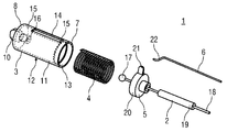
도 3은 메커니즘의 구동 케이블(2)의 운동 및/또는 구동 방향의 역전을 위한 본 발명에 따른 장치(1)의 분해도를 개략적으로 예시한다.
Fig. 3 schematically illustrates an exploded view of the
이러한 장치(1)는 적어도 하우징(3), 스프링 요소(4), 슬라이딩 피스톤(5), 구동 케이블(2) 및 하나 이상의 구동 요소(6)를 포함한다.
Such a
하우징(3)은 바람직하게는 컵 형상의 방식으로 형성되고 개방 제 1 단부(7) 및 폐쇄 제 2 단부(8)를 갖는다. 폐쇄 단부(8)의 외측 상에, 체결 섹션(10)이 하우징(3)의 단부 측(9) 상에 배열될 수 있다. 하우징(3)은 상기 체결 섹션(10)에 의해 차량 내에 또는 프레임 상에 고정되어 배열될 수 있다. 상기 체결 섹션(10)은 예컨대, 대응적으로 형성된 체결 장치(예시되지 않음)에 상호 잠금 및/또는 마찰 방식으로 차량 내에 수용될 수 있는 종래의 형상으로서 디자인될 수 있다. 대안적인 실시예(예시되지 않음)들에서, 가변적인 방식으로 형성될 수 있고 종래의 체결 수단이 배열될 수 있는 종래의 리세스들이 체결 섹션(10)에 도입될 수 있다.
The
하우징(3)의 하우징 벽(11)이 하우징의 외부 둘레(12) 및 내부 둘레(13) 상에 원형 또는 사실상 원형 방식으로 형성되며 금속성 재료, 플라스틱 또는 플라스틱류 혼합물로부터 제작될 수 있다. 그루브 형상의 리세스(14)가 하우징 벽(11) 안으로 도입되고, 그 리세스의 길이방향 크기는 하우징(3)의 길이방향으로 연장하며 하우징 벽(11)을 완전히 관통한다. 리세스(14)의 길이는 여기서 하우징(3)의 길이에 비교하여 감소되고, 따라서 리세스(14)의 단부 측들 상에서, 웨브 영역(15)이 각각의 경우에 단부(7 및 8)들의 방향으로 하우징 벽(11)에 형성된다.
The
폐쇄 단부(8)의 내측 상에서, 수용 섹션(16)이 하우징(3)에 형성되고, 상기 수용 섹션은, 구동 케이블(2)의 단부 측 상에 일체로 형성되는 수용 니플(17)에 대응하는 방식으로 형성되며, 프레임 상에 고정되도록 상기 수용 니플을 상호 잠금 및/또는 마찰 방식으로 수용한다.
On the inside of the closed end 8 a
구동 케이블(2)은 종래의 구동 케이블 또는 연장하는 방향으로 안정적이고 둘레 방향으로 케이블 와이어를 에워싸는 외피(19)와 케이블 와이어(18)의 가변적으로 층을 이룰 수 있는 조합에 의해 기계적 운동 및/또는 인장력을 전달하기 위한 이동 가능한 기계 요소인 케이블 풀(cable pull)이다. 단부 측 상에서, 수용 니플(17)은 케이블 와이어(18) 상에 배열된다.
The
슬라이딩 피스톤(5)은 하우징(3) 내에서 슬라이딩 방식으로 변위 가능하도록 배열되며, 슬라이딩 피스톤(5)의 외부 둘레(20)는 하우징 벽(11)의 내부 둘레(13)에 대응하는 방식으로 형성된다. 슬라이딩 피스톤(5)은 바람직하게는, 예컨대 플라스틱인 재료로부터 제작되며, 이는 하우징(3)의 재료와 낮은 마찰 계수를 갖는 마찰 쌍(friction pairing)을 형성한다.
The
장치(1)의 작동 동안 케이블 와이어(18)가 통과하여 유도되는 구동 케이블(2)의 케이블 와이어(18)용 리드스루가 슬라이딩 피스톤(5) 중앙에 배열되는 반면 구동 케이블(2)의 외피(19)는 슬라이딩 피스톤(5)에 지지된다.
The lead-through of the
구동 요소(6)가 상호 잠금 및/또는 마찰 방식으로 배열될 수 있는 수용 섹션(21)이 슬라이딩 피스톤(5) 상에 일체로 또는 측방향으로 형성된다. 이 목적을 위해, 예컨대 구동 요소(6)의 단부 측 상에 형성되는 체결 섹션(22)이 배열되는 리세스가 수용 섹션(21)에 형성된다.
The receiving
구동 요소(6)는 예컨대 종래의 강성의 둥근 로드(round rod)로서 디자인되고, 그의 제 1 단부에 체결 섹션(22)이 일체로 또는 예컨대 접음(folding) 또는 굽힘(bending)에 의해 형성되며, 그의 제 2 단부는 예시되지 않은 방식으로 메커니즘에 커플링된다.
The
스프링 요소(4)는 바람직하게는 압축 스프링으로서, 예컨대 종래의 헬리컬 스프링으로서 형성되고, 스프링 요소(4)의 제 1 단부가 폐쇄 단부(8)의 내측 상의 하우징(3)에 지지되는 반면, 스프링 요소(4)의 제 2 단부는 슬라이딩 피스톤(5) 상에 작용하는 방식으로 하우징(3)에 배열된다. 스프링 요소(4)는 여기서 하우징 벽(11)의 내부 둘레(13)에 대응하는 방식으로 형성된다.
The
도 4는 메커니즘의 구동 케이블(2)의 운동 및/또는 구동 방향의 역전을 위한 본 발명에 따른 장치(1)의 부분 투시도를 개략적으로 예시한다.
Figure 4 schematically illustrates a partial perspective view of the
장치(1)의 작동 동안, 슬라이딩 피스톤(5)은 구동 케이블(2)에 의해 하우징(3) 내에서 변위된다. 여기서 슬라이딩 피스톤(5)의 방향(X)으로의 변위는 방향(X)의 반대 방향으로의 구동 요소(6)의 운동 및 스프링 요소(4)의 압축을 유발한다. 따라서 구동 케이블(2)의 운동 및/또는 구동 방향의 역전이 달성된다.
During operation of the device (1), the sliding piston (5) is displaced in the housing (3) by means of a drive cable (2). Wherein the displacement of the
압축된 스프링 요소(4)는 방향(X)의 반대 방향으로의 구동 케이블(2) 및 슬라이딩 피스톤(5)의 복귀 운동 및 방향(X)으로의 구동 요소(6)의 결과적인 운동을 보조한다.
The
유리한 실시예(예시되지 않음)에서, 복수의 구동 요소(6)들이 슬라이딩 피스톤(5)의 수용 섹션(21) 상에 배열될 수 있으며, 그 결과 복수의 구동 요소(6)들은 개별 구동 케이블(2)에 의해 동시에 구동될 수 있다. 대안적으로, 복수의 수용 섹션(21)들이 슬라이딩 피스톤(5) 상에 배열될 수 있다. 여기서 구동 요소(6)들의 운동 및/또는 구동 방향은 구동 케이블(2)의 운동 및/또는 구동 방향에 대응할 수 있거나, 구동 케이블(2)의 운동 및/또는 구동 방향의 역전이 일어난다.
A plurality of
다른 유리한 실시예(예시되지 않음)에서, 장치(1)는 보상기로서 디자인될 수 있으며, 구동 케이블(2)의 결함 또는 고장의 경우에, 장치(1)는 구동 요소(6)에 의해 커플링된 메커니즘을 폐쇄한다. 여기서 스프링 요소(4)는 압축된 스프링 요소(4)의 해제가 메커니즘의 클로져를 구동하는 방식으로 형성된다.
In another advantageous embodiment (not illustrated), the
1 장치
2 구동 케이블
3 하우징
4 스프링 요소
5 슬라이딩 피스톤
6 구동 요소
7 제 1 단부
8 제 2 단부
9 단부 측
10 체결 섹션
11 하우징 벽
12 외부 둘레
13 내부 둘레
14 그루브 형상의 리세스
15 웨브 영역
16 수용 섹션
17 수용 니플
18 케이블 와이어
19 외피
20 외부 둘레
21 수용 섹션
22 체결 섹션
X 방향1 device
2 drive cable
3 Housing
4 spring elements
5 sliding piston
6 drive element
7 first end
8 second end
9 End side
10 fastening section
11 Housing wall
12 Outer circumference
13 Inner circumference
14 recessed recess
15 Web area
16 reception sections
17 receiving nipple
18 cable wire
19 Sheath
20 Outer circumference
21 reception section
22 fastening section
X direction
Claims (9)
슬라이딩 피스톤(5)이 프레임 상에 고정되어 배열되는 하우징(3) 내에 슬라이딩 방식으로 변위될 수 있도록 배열되고, 구동 케이블(2)에 의해 변위될 수 있으며, 하나 이상의 구동 요소(6)가 슬라이딩 피스톤(5) 상에 측방향으로 배열되고, 이 구동 요소의 운동 방향은 구동 케이블(2)의 운동 방향에 대향하며 메커니즘에 기계적으로 커플링되는, 메커니즘의 구동 케이블의 운동 및/또는 구동 방향의 역전 장치에 있어서,
그루브 형상의 리세스(14)가 하우징(3)의 하우징 벽(11) 안으로 도입되고, 이 리세스의 길이방향 크기는 하우징(3)의 길이방향으로 연장하고 하우징 벽(11)을 완전히 관통하며, 슬라이딩 피스톤(5)의 수용 섹션(21)은 그루브 형상의 리세스(14) 내에 적어도 부분적으로 배열되는 것을 특징으로 하는,
메커니즘의 구동 케이블의 운동 및/또는 구동 방향의 역전 장치.
A reversing device (1) for the movement and / or drive direction of a drive cable (2) of a mechanism,
A sliding piston (5) is arranged to be displaceable in a sliding manner in a housing (3) fixedly arranged on a frame and can be displaced by a drive cable (2) and one or more driving elements (6) (5), the direction of motion of which is opposed to the direction of movement of the drive cable (2) and which is mechanically coupled to the mechanism, the movement of the drive cable of the mechanism and / In the apparatus,
A recess 14 in the form of a groove is introduced into the housing wall 11 of the housing 3 and the longitudinal extent of the recess extends in the longitudinal direction of the housing 3 and completely penetrates the housing wall 11 , The receiving section (21) of the sliding piston (5) is arranged at least partly in the recess (14) in the shape of a groove.
Device for reversing the movement and / or drive direction of a drive cable of a mechanism.
복수의 구동 요소(6)들이 슬라이딩 피스톤(5) 상에 배열되는 것을 특징으로 하는,
메커니즘의 구동 케이블의 운동 및/또는 구동 방향의 역전 장치.
The method according to claim 1,
Characterized in that a plurality of driving elements (6) are arranged on the sliding piston (5)
Device for reversing the movement and / or drive direction of a drive cable of a mechanism.
상기 구동 요소(6)들의 운동 방향이 구동 케이블(2)의 운동 방향과 동일한 방향으로 또는 이 구동 테이블의 운동 방향에 대향하는 방향으로 형성되는 것을 특징으로 하는,
메커니즘의 구동 케이블의 운동 및/또는 구동 방향의 역전 장치.
3. The method of claim 2,
Characterized in that the moving direction of the driving elements (6) is formed in the same direction as the moving direction of the driving cable (2) or in a direction opposite to the moving direction of the driving table (2)
Device for reversing the movement and / or drive direction of a drive cable of a mechanism.
상기 하우징(3)은 원통형으로 형성되고 개방 제 1 단부(7) 및 폐쇄 제 2 단부(8)를 갖는 것을 특징으로 하는,
메커니즘의 구동 케이블의 운동 및/또는 구동 방향의 역전 장치.
4. The method according to any one of claims 1 to 3,
Characterized in that the housing (3) is formed in a cylindrical shape and has an open first end (7) and a closed second end (8)
Device for reversing the movement and / or drive direction of a drive cable of a mechanism.
상기 폐쇄 단부(8)의 하우징(3)의 외측 상에, 하나 이상의 체결 섹션(10)이 단부 측(9) 상에 및/또는 외부 둘레 상에 배열되는 것을 특징으로 하는,
메커니즘의 구동 케이블의 운동 및/또는 구동 방향의 역전 장치.
5. The method according to any one of claims 1 to 4,
Characterized in that on the outside of the housing (3) of the closed end (8), one or more fastening sections (10) are arranged on the end side (9) and /
Device for reversing the movement and / or drive direction of a drive cable of a mechanism.
상기 폐쇄 단부(8)의 내측 상에, 수용 섹션(16)이 하우징(3)에 형성되고, 상기 수용 섹션은, 구동 케이블(2)의 단부 측 상에 일체로 형성되는 수용 니플(17)에 대응하는 방식으로 형성되고, 프레임 상에 고정되도록 상기 수용 니플을 상호 잠금 및/또는 마찰 방식으로 수용하는 것을 특징으로 하는,
메커니즘의 구동 케이블의 운동 및/또는 구동 방향의 역전 장치.
The method according to claim 4 or 5,
On the inside of the closed end portion 8, a receiving section 16 is formed in the housing 3, and the receiving section is provided with a receiving nipple 17 integrally formed on the end side of the driving cable 2 Characterized in that the receiving nipples are formed in a corresponding manner and are received in a mutual locking and / or frictional manner to be fixed on the frame.
Device for reversing the movement and / or drive direction of a drive cable of a mechanism.
상기 장치(1)의 작동 동안 케이블 와이어(18)가 통과하여 유도되는 구동 케이블(2)의 케이블 와이어(18)용 리드스루(leadthrough)가 슬라이딩 피스톤(5) 중앙에 배열되는 반면, 구동 케이블(2)의 외피(19)는 슬라이딩 피스톤(5)에 지지되는 것을 특징으로 하는,
메커니즘의 구동 케이블의 운동 및/또는 구동 방향의 역전 장치.
7. The method according to any one of claims 4 to 6,
The leadthrough for the cable wire 18 of the drive cable 2 through which the cable wire 18 is guided during operation of the device 1 is arranged in the center of the sliding piston 5, 2) is supported on the sliding piston (5).
Device for reversing the movement and / or drive direction of a drive cable of a mechanism.
스프링 요소(4)를 포함하며 이 스프링 요소는 압축 스프링으로서 디자인되고 스프링 요소(4)의 제 1 단부가 폐쇄 단부(8)의 내측 상의 하우징(3)에 지지되는 반면, 스프링 요소(4)의 제 2 단부는 슬라이딩 피스톤(5) 상에 작용하는 방식으로 하우징(3)에 배열되는 것을 특징으로 하는,
메커니즘의 구동 케이블의 운동 및/또는 구동 방향의 역전 장치.
8. The method according to any one of claims 4 to 7,
The spring element 4 is designed as a compression spring and the first end of the spring element 4 is supported on the housing 3 on the inside of the closed end 8, Characterized in that the second end is arranged in the housing (3) in such a way as to act on the sliding piston (5)
Device for reversing the movement and / or drive direction of a drive cable of a mechanism.
상기 장치(1)는 구동 케이블(2)의 결함 또는 고장의 경우에, 구동 요소(6)에 의해 커플링되는 메커니즘이 폐쇄될 수 있는 방식으로 보상기로서 디자인되고, 스프링 요소(4)는 압축된 스프링 요소(4)의 해제가 메커니즘의 클로져를 구동하는 방식으로 형성되는 것을 특징으로 하는,
메커니즘의 구동 케이블의 운동 및/또는 구동 방향의 역전 장치. 9. The method of claim 8,
The device 1 is designed as a compensator in such a way that in the event of a fault or failure of the drive cable 2 the mechanism coupled by the drive element 6 can be closed and the spring element 4 is compressed Characterized in that the release of the spring element (4) is formed in such a way as to drive the closure of the mechanism.
Device for reversing the movement and / or drive direction of a drive cable of a mechanism.
Applications Claiming Priority (3)
| Application Number | Priority Date | Filing Date | Title |
|---|---|---|---|
| DE102012201709.7A DE102012201709B4 (en) | 2012-02-06 | 2012-02-06 | Device for reversing the direction of movement and / or actuation of a control cable of a mechanism |
| DE102012201709.7 | 2012-02-06 | ||
| PCT/EP2013/052124 WO2013117510A1 (en) | 2012-02-06 | 2013-02-04 | Device for reversing the movement and/or actuation direction of an actuating cable of a mechanism |
Publications (2)
| Publication Number | Publication Date |
|---|---|
| KR20140114905A true KR20140114905A (en) | 2014-09-29 |
| KR101660234B1 KR101660234B1 (en) | 2016-09-27 |
Family
ID=47678788
Family Applications (1)
| Application Number | Title | Priority Date | Filing Date |
|---|---|---|---|
| KR1020147025009A KR101660234B1 (en) | 2012-02-06 | 2013-02-04 | Device for reversing the movement and/or actuation direction of an actuating cable of a mechanism |
Country Status (8)
| Country | Link |
|---|---|
| US (1) | US9279443B2 (en) |
| EP (1) | EP2812588B8 (en) |
| JP (1) | JP6131276B2 (en) |
| KR (1) | KR101660234B1 (en) |
| CN (1) | CN104094001B (en) |
| DE (1) | DE102012201709B4 (en) |
| IN (1) | IN2014DN06142A (en) |
| WO (1) | WO2013117510A1 (en) |
Families Citing this family (4)
| Publication number | Priority date | Publication date | Assignee | Title |
|---|---|---|---|---|
| US10379788B2 (en) * | 2016-06-10 | 2019-08-13 | Ricoh Company, Ltd. | Operation device configured to display a configuration of an image forming device and information processing system including same |
| US11014419B2 (en) | 2017-03-21 | 2021-05-25 | Arctic Cat Inc. | Off-road utility vehicle |
| US10717474B2 (en) | 2017-03-21 | 2020-07-21 | Arctic Cat Inc. | Cab and fasteners for vehicle cab |
| US11046176B2 (en) * | 2017-03-21 | 2021-06-29 | Arctic Cat Inc. | Off-road utility vehicle |
Citations (4)
| Publication number | Priority date | Publication date | Assignee | Title |
|---|---|---|---|---|
| JPH0747610Y2 (en) * | 1988-02-18 | 1995-11-01 | トヨタ自動車株式会社 | Control cable terminal connection device |
| JP2001304233A (en) * | 2000-04-20 | 2001-10-31 | Bio Oriented Technol Res Advancement Inst | Cable system with on/off mechanism |
| JP2007016588A (en) * | 2005-07-08 | 2007-01-25 | Stabilus Gmbh | Flap rotating device |
| US20110140461A1 (en) * | 2009-12-15 | 2011-06-16 | Honda Motor Co., Ltd. | Mechanical tailgate locking system |
Family Cites Families (7)
| Publication number | Priority date | Publication date | Assignee | Title |
|---|---|---|---|---|
| GB166655A (en) * | 1920-04-12 | 1921-07-12 | Bowden Wire Ltd | Improvements in or connected with bowden wire and like mechanism |
| JPS5917621A (en) * | 1982-07-20 | 1984-01-28 | Nissan Motor Co Ltd | Device for taking out transmission force of push-pull cable |
| US4683774A (en) * | 1984-03-08 | 1987-08-04 | Delta Elettronica S.R.L. | Bowden cable |
| ES2024819A6 (en) | 1990-05-31 | 1992-03-01 | Pujol & Tarago | Self adjusting mechanism for the adjustment of the length of control cables. |
| DE4325417A1 (en) * | 1993-07-29 | 1995-02-02 | Hydraulik Ring Gmbh | Actuating device for the throttle valve of a carburetor in automatic transmissions of motor vehicles |
| ES2128935B1 (en) | 1996-05-14 | 2000-02-01 | Fico Cables Sa | ADJUSTER DEVICE FOR CONTROL CABLE TERMINALS. |
| FR2765926B1 (en) * | 1997-07-10 | 1999-10-01 | Peugeot | DEVICE FOR CONTROLLING A RECEIVING CONTROL MEMBER BY A TRANSMITTER CONTROL MEMBER |
-
2012
- 2012-02-06 DE DE102012201709.7A patent/DE102012201709B4/en not_active Expired - Fee Related
-
2013
- 2013-02-04 EP EP13703019.3A patent/EP2812588B8/en not_active Not-in-force
- 2013-02-04 JP JP2014555241A patent/JP6131276B2/en not_active Expired - Fee Related
- 2013-02-04 CN CN201380008152.XA patent/CN104094001B/en not_active Expired - Fee Related
- 2013-02-04 WO PCT/EP2013/052124 patent/WO2013117510A1/en active Application Filing
- 2013-02-04 US US14/376,915 patent/US9279443B2/en not_active Expired - Fee Related
- 2013-02-04 KR KR1020147025009A patent/KR101660234B1/en active IP Right Grant
- 2013-02-04 IN IN6142DEN2014 patent/IN2014DN06142A/en unknown
Patent Citations (4)
| Publication number | Priority date | Publication date | Assignee | Title |
|---|---|---|---|---|
| JPH0747610Y2 (en) * | 1988-02-18 | 1995-11-01 | トヨタ自動車株式会社 | Control cable terminal connection device |
| JP2001304233A (en) * | 2000-04-20 | 2001-10-31 | Bio Oriented Technol Res Advancement Inst | Cable system with on/off mechanism |
| JP2007016588A (en) * | 2005-07-08 | 2007-01-25 | Stabilus Gmbh | Flap rotating device |
| US20110140461A1 (en) * | 2009-12-15 | 2011-06-16 | Honda Motor Co., Ltd. | Mechanical tailgate locking system |
Also Published As
| Publication number | Publication date |
|---|---|
| EP2812588A1 (en) | 2014-12-17 |
| JP6131276B2 (en) | 2017-05-17 |
| DE102012201709A1 (en) | 2013-08-08 |
| DE102012201709B4 (en) | 2015-06-25 |
| US20150033881A1 (en) | 2015-02-05 |
| EP2812588B8 (en) | 2017-08-16 |
| KR101660234B1 (en) | 2016-09-27 |
| EP2812588B1 (en) | 2017-06-28 |
| CN104094001A (en) | 2014-10-08 |
| JP2015508146A (en) | 2015-03-16 |
| WO2013117510A1 (en) | 2013-08-15 |
| US9279443B2 (en) | 2016-03-08 |
| IN2014DN06142A (en) | 2015-08-21 |
| CN104094001B (en) | 2016-08-24 |
Similar Documents
| Publication | Publication Date | Title |
|---|---|---|
| KR20140114905A (en) | Device for reversing the movement and/or actuation direction of an actuating cable of a mechanism | |
| US20160089996A1 (en) | Charging stand | |
| US9308833B2 (en) | Harness wiring apparatus | |
| EP1479921B1 (en) | Stop device with shape memory actuator | |
| US20080022802A1 (en) | Shift lever | |
| US20160258474A1 (en) | Cable Connection Apparatus for Vehicles | |
| JP6396843B2 (en) | Window regulator | |
| JP2017528364A (en) | Luggage fixing device | |
| US20050179280A1 (en) | Device for opening and closing a vehicle body part | |
| US9896873B2 (en) | Tension applying apparatus, drum apparatus and opening and closing body drive apparatus for vehicle | |
| JP3862150B2 (en) | Wire harness surplus length absorber | |
| WO2019096433A8 (en) | Length-adjustable support device | |
| JP2005530973A (en) | Drive, length-adjustable housing and furniture for displacing profile parts relative to one another via strips of flexible material | |
| US9586540B2 (en) | Cable anchoring device | |
| JP6477017B2 (en) | Wire lock structure for boom extension | |
| EP2650464A3 (en) | Rollo assembly and open roof construction for a vehicle provided therewith | |
| KR20150017508A (en) | Low Tele Friction type Column Module and Motor Driven Power Steering therefor | |
| CN107054287B (en) | Buckle device | |
| KR101673781B1 (en) | Vehicle transmission lever apparatus | |
| CN102647048B (en) | Stroke limit device used for linear actuator and take-up mechanism thereof | |
| CN105873787A (en) | Kick-down element for motor vehicle | |
| US20190219096A1 (en) | Ball joint device | |
| JP5543797B2 (en) | Power feeding device for slide structure | |
| KR102401173B1 (en) | Adjusting instrument, exterior mirror unit, motor vehicle | |
| KR101631982B1 (en) | Electronic parking brake |
Legal Events
| Date | Code | Title | Description |
|---|---|---|---|
| A201 | Request for examination | ||
| E902 | Notification of reason for refusal | ||
| E90F | Notification of reason for final refusal | ||
| E701 | Decision to grant or registration of patent right | ||
| GRNT | Written decision to grant | ||
| FPAY | Annual fee payment |
Payment date: 20190916 Year of fee payment: 4 |