KR20140098967A - Pipe coupler using pressure type packing member - Google Patents
Pipe coupler using pressure type packing member Download PDFInfo
- Publication number
- KR20140098967A KR20140098967A KR1020130011555A KR20130011555A KR20140098967A KR 20140098967 A KR20140098967 A KR 20140098967A KR 1020130011555 A KR1020130011555 A KR 1020130011555A KR 20130011555 A KR20130011555 A KR 20130011555A KR 20140098967 A KR20140098967 A KR 20140098967A
- Authority
- KR
- South Korea
- Prior art keywords
- pipe
- coupler
- pressing
- packing member
- sealing ring
- Prior art date
Links
Images


Classifications
-
- F—MECHANICAL ENGINEERING; LIGHTING; HEATING; WEAPONS; BLASTING
- F16—ENGINEERING ELEMENTS AND UNITS; GENERAL MEASURES FOR PRODUCING AND MAINTAINING EFFECTIVE FUNCTIONING OF MACHINES OR INSTALLATIONS; THERMAL INSULATION IN GENERAL
- F16L—PIPES; JOINTS OR FITTINGS FOR PIPES; SUPPORTS FOR PIPES, CABLES OR PROTECTIVE TUBING; MEANS FOR THERMAL INSULATION IN GENERAL
- F16L37/00—Couplings of the quick-acting type
- F16L37/08—Couplings of the quick-acting type in which the connection between abutting or axially overlapping ends is maintained by locking members
- F16L37/084—Couplings of the quick-acting type in which the connection between abutting or axially overlapping ends is maintained by locking members combined with automatic locking
- F16L37/0845—Couplings of the quick-acting type in which the connection between abutting or axially overlapping ends is maintained by locking members combined with automatic locking by means of retaining members associated with the packing member
-
- F—MECHANICAL ENGINEERING; LIGHTING; HEATING; WEAPONS; BLASTING
- F16—ENGINEERING ELEMENTS AND UNITS; GENERAL MEASURES FOR PRODUCING AND MAINTAINING EFFECTIVE FUNCTIONING OF MACHINES OR INSTALLATIONS; THERMAL INSULATION IN GENERAL
- F16L—PIPES; JOINTS OR FITTINGS FOR PIPES; SUPPORTS FOR PIPES, CABLES OR PROTECTIVE TUBING; MEANS FOR THERMAL INSULATION IN GENERAL
- F16L37/00—Couplings of the quick-acting type
- F16L37/08—Couplings of the quick-acting type in which the connection between abutting or axially overlapping ends is maintained by locking members
- F16L37/084—Couplings of the quick-acting type in which the connection between abutting or axially overlapping ends is maintained by locking members combined with automatic locking
- F16L37/086—Couplings of the quick-acting type in which the connection between abutting or axially overlapping ends is maintained by locking members combined with automatic locking by means of latching members pushed radially by spring-like elements
Abstract
BACKGROUND OF THE INVENTION 1. Field of the Invention The present invention relates to a piping coupler using a pressurized packing member, and more particularly, to a piping coupler comprising a sealing ring having grooves and projections of different sizes and a compression ring, To a piping coupler using a pressurized packing member capable of ensuring reliable watertightness or airtightness of joints or gaps of a pipe body.
A pipe coupler using a pressurized packing member according to the present invention is a pipe coupler for connecting a pipe through which a fluid is moved in a watertight or hermetic manner, wherein a hollow is formed along the longitudinal direction, A coupler body communicating with the pipe; Pipe fixing means for fixing the pipe inserted into the coupler main body; A packing member which is fastened to the hollow of the coupler body and inserted into the pipe to insert the pipe therein and which has elasticity to seal a gap between the coupler body and the pipe; Wherein the packing member includes an annular sealing ring formed by laminating a pressing groove along a circumferential direction on a lamination surface of a front surface or a rear surface and having a wing extending in both widthwise directions in the pressing groove, And an annular pressing ring having a shape larger than the pressing groove in a circumferential direction on a surface of the sealing ring, the pressing ring being inserted into the pressing groove and being laminated on the sealing ring, A pressing means for pressing the pressing ring in such a direction as to press the sealing ring against each other so as to seal the clearance between the coupler main body and the pipe, the wing portion being opened in both widthwise directions; Wherein the pressing means includes a pressing spring disposed behind the packing member and elastically pressing the packing member forward.
Description
BACKGROUND OF THE
The packing member refers to a member that is fastened to a joint or gap of a watertight or hermetic tube body, and conventionally, an O-ring formed of a material having elasticity such as rubber or the like and having a circular or square cross section and formed into an annular shape is mainly used as a packing member come.
However, with the conventional O-ring used as a packing member, there has been a limit to sealing the seam or the gap of the tubular body reliably, particularly when a high-pressure fluid flows due to the limit of volume change due to elasticity.
In addition, the piping work is generally referred to as a work for forming a pipeline by cutting and connecting a plurality of pipes in accordance with the installation environment to a predetermined length, and in the piping work as described above, Piping couplers are used because of necessity.
Conventionally used piping couplers are provided with a plurality of connecting portions having the same inner diameter as a pipe to be connected and having an outer diameter larger than a pipe to be connected and formed with a helical groove so that a pipe can be inserted into the pipe in a threaded manner.
However, such a conventional conventional pipe coupler has to be inserted while rotating the pipe, so that the airtightness and the workability are not easy.
In order to solve the disadvantages of the conventional conventional piping coupler, a pipe connecting device having a packing member has been proposed in the registration utility model No. 0381922 (registered on Apr. 04, 2005).
FIG. 1 shows a conventional piping coupler disclosed in the above registered utility model No. 0381922. FIG.
Referring to FIG. 1, a pipe coupler according to the related art includes a hollow body 10 'having a plurality of open connection portions into which pipes to be connected are formed, A support ring 30 'which is inserted into the connection portion and is in close contact with the packing member 20' and has an inclined surface whose inner surface is downwardly downwardly formed, A fixture 40 'which is placed on an inclined surface of the ring 30' and is closely attached, the fixture 40 'having a plurality of fixtures for pressing and fixing the outer surface of the pipe inserted and connected to the inside of the connection, And a locking nut 50 'fastened to the end of the connection portion by a screw and tightly fixed to the fixture 40' are sequentially installed.
However, as shown in FIG. 1, the piping coupler according to the related art has only an O-ring as an example of the packing member 20 '. However, owing to the limitation of volume change due to elasticity, There is a limit to maintaining the watertightness or airtightness of the pipe securely.
SUMMARY OF THE INVENTION The present invention has been made in order to solve the problems of the prior art as described above, and it is an object of the present invention to provide a packing member comprising a sealing ring having grooves and projections of different sizes, And the wing portion of the sealing ring is widened in the widthwise direction by the pressure ring, thereby ensuring reliable watertightness or airtightness of the joint or gap of the pipe.
In order to achieve the above object, a piping coupler using a pressurized packing member according to the present invention is a pipe coupler for connecting a pipe through which a fluid is moved in a watertight or hermetic manner, wherein a hollow is formed along the longitudinal direction, A coupler main body inserted into the pipe in front of the pipe and communicating with the pipe; Pipe fixing means for fixing the pipe inserted into the coupler main body; A packing member which is fastened to the hollow of the coupler body and inserted into the pipe to insert the pipe therein and which has elasticity to seal a gap between the coupler body and the pipe; Wherein the packing member includes an annular sealing ring formed by laminating a pressing groove along a circumferential direction on a lamination surface of a front surface or a rear surface and having a wing extending in both widthwise directions in the pressing groove, And an annular pressing ring having a shape larger than the pressing groove in a circumferential direction on a surface of the sealing ring, the pressing ring being inserted into the pressing groove and being laminated on the sealing ring, A pressing means for pressing the pressing ring in such a direction as to press the sealing ring against each other so as to seal the clearance between the coupler main body and the pipe, the wing portion being opened in both widthwise directions; Wherein the pressing means includes a pressing spring disposed behind the packing member and elastically pressing the packing member forward.
In the piping coupler using the pressurized packing member according to the present invention, the pipe fastening means is fastened to the hollow of the coupler main body, and the pipe is inserted into the pipe, but is opened by an external force of insertion of the pipe, And a fastening piece which is fastened by an elastic restoring force and has a cutout formed on one side thereof so as to be able to restrain the pipe.
The piping coupler using the pressurized packing member according to the present invention is characterized in that the tightening piece is fastened to the hollow of the coupler body so as to be movable back and forth and has an oblique tapered surface in the form of a tube- When the tightening member is moved rearward by an external force of insertion of the pipe, the tightening member is opened to induce the inner diameter to be expanded so that the pipe slips, and the urging force of the urging member, transmitted through the packing member, Further comprising a tightening cap having a cap tapered surface having a shape corresponding to an inclined tapered surface of the tightening member on an inner surface of a front end of the coupler body so as to guide the tightening piece to be tightened when the pipe is moved forward, .
Further, the piping coupler using the pressurized packing member according to the present invention includes a pipe dismounting means for releasing the restraint of the pipe by the user's operation in a state where the pipe is held by the pipe securing means; Wherein the pipe disassembling means is coupled to the front end portion of the coupler body so as to be movable back and forth with an inner diameter larger than the outer diameter of the pipe so that the pipe passes through the pipe, And a push button for opening the fastening piece and expanding the inner diameter.
The pipe coupler using the pressurized packing member according to the present invention is characterized in that the fastening piece has an induction tapered surface at a front end portion of the inner circumferential surface so that insertion of the push button is guided into the fastener.
In the piping coupler using the pressurized packing member according to the present invention, the pipe fixing means, the packing means, and the pressurizing means are sequentially stacked from the front in the hollow interior of the coupler main body, A plurality of pipes arranged in an inclined manner in such a manner that an inner diameter of the pipe is reduced toward the rear of the pipe so as to prevent the pipe from being released in the other direction, And a tension washer having a number of radiating pieces.
Further, the piping coupler using the pressurized packing member according to the present invention includes a pipe dismounting means for releasing the restraint of the pipe by the user's operation in a state where the pipe is held by the pipe securing means; Wherein the pipe disassembling means is coupled to the front end portion of the coupler main body so as to be movable back and forth with an inner diameter larger than the outer diameter of the pipe so that the pipe passes through the pipe, And a push button inserted into the ring to expand the inner diameter of the radiating piece.
According to the above construction, in the piping coupler using the pressurized packing member according to the present invention, when the packing member is compressed by the pressurizing means, the wing portion of the sealing ring is opened by the pressurizing ring in both widthwise directions, There is an advantage that the watertightness or airtightness of the gap can be assured.
1 is an exploded perspective view of a piping coupler according to the prior art;
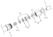
2 is an exploded perspective view of a piping coupler using a pressurized packing member according to the first embodiment of the present invention.
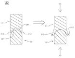
3 is a cross-sectional view of the main portion of the pressurized packing member according to the first embodiment of the present invention
4 to 7 are cross-sectional views of the piping coupler using the pressurized packing member according to the first embodiment of the present invention
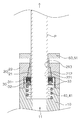
8 is an exploded perspective view of a piping coupler using a pressurized packing member according to a second embodiment of the present invention.
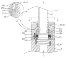
9 to 11 are cross-sectional views of the piping coupler using the pressurized packing member according to the second embodiment of the present invention
Hereinafter, a piping coupler using a pressurized packing member according to the present invention will be described in detail with reference to the embodiments shown in the drawings.
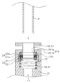
FIG. 2 is an exploded perspective view of a piping coupler using a pressurized packing member according to a first embodiment of the present invention, FIG. 3 is a sectional view of a main portion of a pressurized packing member according to the first embodiment of the present invention, 7 is a sectional view of the piping coupler using the pressurized packing member according to the first embodiment of the present invention.
The piping coupler using the pressurized packing member according to the first embodiment of the present invention includes a
The
In the first embodiment of the present invention, the pipe (P) is inserted into and connected to the hollow (11) from the one side of the coupler body (10) And may be formed into various shapes such as a T shape, a cruciform shape, as well as a straight shape connected to a date.
The pipe fixing means 20 fixes the pipe P inserted into the coupler
The fastening
The
The inclined
The guiding
The tightening
5, when the
The
The sealing
The
3, the
Meanwhile, it is preferable that
The pressing means 40 presses the
When the
The pipe dismounting means 50 is configured to release the restraint of the pipe P by the user's operation in a state where the pipe P is restrained by the pipe securing means 20, In the example, the push button 51 is included.
The push button 51 has an inner diameter larger than the outer diameter of the pipe so that the pipe P passes through the pipe and is coupled to the front end of the
7, when the push button 51 is moved backward by an external force of the user as shown in FIG. 7, The push button 51 is smoothly inserted into the tightening
4 shows an initial state of a piping coupler using a pressurized packing member according to the first embodiment of the present invention. In this case, the
5 shows a case where the pipe P is inserted into the
6 shows a state in which an external force is applied to the
7 shows a state in which the pipe P is disassembled from the coupler
Hereinafter, the piping coupler using the pressurized packing member according to the first embodiment of the present invention has been described. Hereinafter, the piping coupler using the pressurized packing member according to the second embodiment of the present invention will be described in detail.
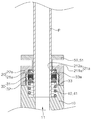
FIG. 8 is an exploded perspective view of the piping coupler using the pressurized packing member according to the second embodiment of the present invention, and FIGS. 9 to 11 are sectional views of the piping coupler using the pressurized packing member according to the second embodiment of the present invention to be.
The piping coupler using the pressurized packing member according to the second embodiment of the present invention is similar to the first embodiment of the present invention in that the
The piping coupler using the pressurized packing member according to the second embodiment of the present invention is constructed such that the pipe fixing means 20, the packing means 30, and the pressurizing means 30 are provided in the hollow 11 of the
The pipe fixing means 20 fixes the pipe P inserted into the coupler
The
That is, due to the configuration of the plurality of radiating
The fixing
The packing
The pipe dismounting means 50 is configured to release the restraint of the pipe P by the user's operation in a state in which the pipe P is restrained by the pipe securing means 20, In the example, the push button 51 is included.
The push button 51 has an inner diameter larger than the outer diameter of the pipe so that the pipe P passes through the pipe and is coupled to the front end of the
FIG. 9 shows an initial state of a piping coupler using a pressurized packing member according to a second embodiment of the present invention, and FIG. 10 shows a state in which the pipe P is fixed by the
11 shows a state in which the pipe P is disassembled from the coupler
The piping coupler using the pressurized packing member described above and shown in the drawings is only one embodiment for carrying out the present invention and should not be construed as limiting the technical idea of the present invention. The scope of protection of the present invention is defined only by the matters set forth in the following claims, and the embodiments improved and changed without departing from the gist of the present invention are obvious to those having ordinary skill in the art to which the present invention belongs It will be understood that the invention is not limited thereto.
P pipe
10 Coupler Body
11 hollow
20 Pipe fastening means
21 Fastening
211 incision
212 Inclined taper face
213 Induced Taper Face
22 Fastening cap
221 Cap Taper Face
21a tension washer
211a
212a radiation piece
22a fixed cap
30 packing member
31 Sealing ring
311 Pressurized Groove
312 wing portion
32 Pressurizing ring
321 pressing projection
40 pressure means
41 pressure spring
50 pipe dismantling means
51 Push Button
Claims (7)
A coupler main body having a hollow formed along a longitudinal direction thereof, the pipe inserted into a front of the hollow and communicating with the pipe; Pipe fixing means for fixing the pipe inserted into the coupler main body; A packing member which is fastened to the hollow of the coupler body and inserted into the pipe to insert the pipe therein and which has elasticity to seal a gap between the coupler body and the pipe; Including,
Wherein the packing member comprises an annular sealing ring formed by laminating a pressing groove along a circumferential direction on a lamination surface on a front surface or a rear surface and having a wing extending in both widthwise directions in the pressing groove, And an annular pressing ring having a shape larger than the pressing groove along the circumferential direction on the contacted surface and formed with pressing protrusions inserted into the pressing groove and stacked on the sealing ring,
A pressing means for pressing the sealing ring in such a direction as to press the pressing ring and the sealing ring to seal the gap between the coupler main body and the pipe, the wing portion of the sealing ring being opened in both widthwise directions; Further included,
Wherein the pressing means includes a pressing spring which is disposed at the rear of the packing member and elastically presses the packing member forward.
The pipe fixing means includes a pipe fixing portion that is fastened to the hollow of the coupler body to insert the pipe therein, is opened by an external force of insertion of the pipe, is expanded by an inner diameter, is tightened by an elastic restoring force, And a fastening piece having a cut-out portion formed in the pipe.
Wherein the fastening piece is fastened to the hollow of the coupler body so as to be movable back and forth,
Wherein the pipe fixing means guides the tightening member to open when the tightening member is moved rearward due to an external force of insertion of the pipe to allow the pipe to slip so that the tightening member can be slid, Wherein the fastening member is fastened to the fastening member when the fastening member is moved forward by elastic pressure of the fastening member, and a cap tapered surface having a shape corresponding to an inclined tapered surface of the fastening member is formed on the inner surface of the front end of the coupler body, Wherein the piping coupler is formed of a plastic material.
A pipe dismounting means for releasing the restraint of the pipe by a user's operation in a state where the pipe is restrained by the pipe securing means; Further included,
Wherein the pipe disassembling means is inserted into the fastening member and is inserted into the fastening member with an inner diameter larger than an outer diameter of the pipe so as to allow the pipe to pass therethrough, And a push button for expanding an inner diameter of the pipe to expand the tightening piece.
Wherein the fastening piece is formed with an induction tapered surface at a front end portion of the inner circumferential surface so that insertion of the push button is guided into the fastening piece.
The pipe fixing means, the packing means, and the pressing means are sequentially stacked from the front in the hollow interior of the coupler main body,
The pipe fixing means includes a ring portion which is fastened to the hollow of the coupler main body and through which the pipe passes, and a pipe fixing portion which is inserted into the pipe in one direction, And a tension washer having a plurality of radiating pieces arranged obliquely to each other in a downwardly curved shape.
A pipe dismounting means for releasing the restraint of the pipe by a user's operation in a state where the pipe is restrained by the pipe securing means; Further included,
Wherein the pipe disassembling means has an inner diameter larger than an outer diameter of the pipe so that the pipe passes through the pipe and is moved backward by an external force so as to be movable back and forth at a front end portion of the coupler main body, And a push button for inserting the push button to expand the inner diameter of the radiating piece.
Priority Applications (2)
| Application Number | Priority Date | Filing Date | Title |
|---|---|---|---|
| KR1020130011555A KR20140098967A (en) | 2013-02-01 | 2013-02-01 | Pipe coupler using pressure type packing member |
| PCT/KR2013/008501 WO2014051298A1 (en) | 2012-09-28 | 2013-09-24 | Pipe coupler using pressure type packing member |
Applications Claiming Priority (1)
| Application Number | Priority Date | Filing Date | Title |
|---|---|---|---|
| KR1020130011555A KR20140098967A (en) | 2013-02-01 | 2013-02-01 | Pipe coupler using pressure type packing member |
Publications (1)
| Publication Number | Publication Date |
|---|---|
| KR20140098967A true KR20140098967A (en) | 2014-08-11 |
Family
ID=51745514
Family Applications (1)
| Application Number | Title | Priority Date | Filing Date |
|---|---|---|---|
| KR1020130011555A KR20140098967A (en) | 2012-09-28 | 2013-02-01 | Pipe coupler using pressure type packing member |
Country Status (1)
| Country | Link |
|---|---|
| KR (1) | KR20140098967A (en) |
Cited By (2)
| Publication number | Priority date | Publication date | Assignee | Title |
|---|---|---|---|---|
| KR102007222B1 (en) * | 2018-09-20 | 2019-08-05 | 주식회사 강동엔지니어링 | Reinforcing apparatus for tunnel and reinforcing method using the same |
| KR20220029094A (en) * | 2020-09-01 | 2022-03-08 | 김병섭 | Pipe end sealed type coupler |
-
2013
- 2013-02-01 KR KR1020130011555A patent/KR20140098967A/en active IP Right Grant
Cited By (2)
| Publication number | Priority date | Publication date | Assignee | Title |
|---|---|---|---|---|
| KR102007222B1 (en) * | 2018-09-20 | 2019-08-05 | 주식회사 강동엔지니어링 | Reinforcing apparatus for tunnel and reinforcing method using the same |
| KR20220029094A (en) * | 2020-09-01 | 2022-03-08 | 김병섭 | Pipe end sealed type coupler |
Similar Documents
| Publication | Publication Date | Title |
|---|---|---|
| RU2517268C2 (en) | Pipeline joint | |
| EP3521675A1 (en) | Pipe fitting connecting method and connecting structure | |
| KR101489711B1 (en) | Connector for branch pipe | |
| KR20140098967A (en) | Pipe coupler using pressure type packing member | |
| KR101538337B1 (en) | Pipe connection and pipe assembly | |
| KR20110002990A (en) | Pipe connecting apparatus using packing of hollow pipe type | |
| KR20170112081A (en) | The one touch type coupler for plumbing connection | |
| KR101441548B1 (en) | Coupling device of hydraulic hose couplings | |
| KR101260046B1 (en) | Pressure type packing member and one touch pipe coupler using thereof | |
| KR20160004240U (en) | Clamp for connecting pipes | |
| KR101857027B1 (en) | Spring band sealed type one touch pipe coupler | |
| KR101773751B1 (en) | The connecting socket for a pipe | |
| KR101709723B1 (en) | Pipe connector | |
| KR20150070924A (en) | Pipe coupler able to connect easily | |
| JP2015197195A (en) | Narrow place piping joint | |
| JP2007218415A (en) | Connection end and connection end body for water pipe, engagement element and in-core for water pipe connection, water pipe body, connection structure and protective cap for water pipe, water pipe system, and connection end forming tool for water pipe | |
| JP6611430B2 (en) | Waterproof structure | |
| KR102018818B1 (en) | Rigid polyvinyl chloride pipe with insertion restriction and escape prevention | |
| KR20150004585A (en) | Pipe coupler connecting a pipe easily | |
| KR101351201B1 (en) | Pipe fastening apparatus and method | |
| KR20150109122A (en) | Pipe coupler having double pressure spring | |
| JP2010096230A (en) | Pipe joint | |
| KR20100077883A (en) | An assembly for pressed o-ring type one touch pipe joint | |
| JP2001311492A (en) | Slip-on pipe joint | |
| KR101186550B1 (en) | Pipe coupling assembly |
Legal Events
| Date | Code | Title | Description |
|---|---|---|---|
| A201 | Request for examination | ||
| E902 | Notification of reason for refusal | ||
| E902 | Notification of reason for refusal | ||
| E701 | Decision to grant or registration of patent right |