KR20140096056A - Switching system - Google Patents
Switching system Download PDFInfo
- Publication number
- KR20140096056A KR20140096056A KR1020147012722A KR20147012722A KR20140096056A KR 20140096056 A KR20140096056 A KR 20140096056A KR 1020147012722 A KR1020147012722 A KR 1020147012722A KR 20147012722 A KR20147012722 A KR 20147012722A KR 20140096056 A KR20140096056 A KR 20140096056A
- Authority
- KR
- South Korea
- Prior art keywords
- switching system
- contact
- link
- bearing
- arc
- Prior art date
Links
Images


Classifications
-
- H—ELECTRICITY
- H01—ELECTRIC ELEMENTS
- H01H—ELECTRIC SWITCHES; RELAYS; SELECTORS; EMERGENCY PROTECTIVE DEVICES
- H01H33/00—High-tension or heavy-current switches with arc-extinguishing or arc-preventing means
- H01H33/02—Details
- H01H33/04—Means for extinguishing or preventing arc between current-carrying parts
- H01H33/18—Means for extinguishing or preventing arc between current-carrying parts using blow-out magnet
- H01H33/182—Means for extinguishing or preventing arc between current-carrying parts using blow-out magnet using permanent magnets
-
- H—ELECTRICITY
- H01—ELECTRIC ELEMENTS
- H01H—ELECTRIC SWITCHES; RELAYS; SELECTORS; EMERGENCY PROTECTIVE DEVICES
- H01H1/00—Contacts
- H01H1/12—Contacts characterised by the manner in which co-operating contacts engage
- H01H1/14—Contacts characterised by the manner in which co-operating contacts engage by abutting
- H01H1/20—Bridging contacts
- H01H1/2041—Rotating bridge
-
- H—ELECTRICITY
- H01—ELECTRIC ELEMENTS
- H01H—ELECTRIC SWITCHES; RELAYS; SELECTORS; EMERGENCY PROTECTIVE DEVICES
- H01H50/00—Details of electromagnetic relays
- H01H50/54—Contact arrangements
-
- H—ELECTRICITY
- H01—ELECTRIC ELEMENTS
- H01H—ELECTRIC SWITCHES; RELAYS; SELECTORS; EMERGENCY PROTECTIVE DEVICES
- H01H9/00—Details of switching devices, not covered by groups H01H1/00 - H01H7/00
- H01H9/30—Means for extinguishing or preventing arc between current-carrying parts
- H01H9/34—Stationary parts for restricting or subdividing the arc, e.g. barrier plate
- H01H9/36—Metal parts
-
- H—ELECTRICITY
- H01—ELECTRIC ELEMENTS
- H01H—ELECTRIC SWITCHES; RELAYS; SELECTORS; EMERGENCY PROTECTIVE DEVICES
- H01H9/00—Details of switching devices, not covered by groups H01H1/00 - H01H7/00
- H01H9/30—Means for extinguishing or preventing arc between current-carrying parts
- H01H9/44—Means for extinguishing or preventing arc between current-carrying parts using blow-out magnet
- H01H9/443—Means for extinguishing or preventing arc between current-carrying parts using blow-out magnet using permanent magnets
Landscapes
- Physics & Mathematics (AREA)
- Electromagnetism (AREA)
- Arc-Extinguishing Devices That Are Switches (AREA)
- Breakers (AREA)
- Chutes (AREA)
Abstract
본 발명은, 특히 2개의 접촉 포인트들(4a, 4b) 사이의 회전축(6) 주위에 회전가능하게 배치된 접촉 브릿지(5)를 가지는 HV(DC) 릴레이 또는 접촉기를 위한 스위칭 시스템(1)에 관한 것이다. 스위칭 시스템(1)은 접촉 포인트들(4a, 4b)이 개방될 때, 광 아크를 소호 챔버(16)로 드라이빙하기 위한 자기 엘리먼트(15)를 또한 포함한다.The present invention relates to a switching system 1 for an HV (DC) relay or contactor with a contact bridge 5 rotatably arranged about the axis of rotation 6, in particular between two contact points 4a, 4b . The switching system 1 also includes a magnetic element 15 for driving the light arc into the soho chamber 16 when the contact points 4a and 4b are open.
Description
본 발명은 2 개의 접촉 포인트(contact point)들 사이에 이동가능한 접촉 링크를 포함하는 스위칭 시스템에 관한 것이다. 스위칭 시스템은 특히 높은 DC 전압들, 바람직하게는 HVDC(high-voltage direct current) 릴레이 또는 접촉기(contactor)에 대해 의도된 것이다.The present invention relates to a switching system including a movable contact link between two contact points. The switching system is intended especially for high DC voltages, preferably high-voltage direct current (HVDC) relays or contactors.
DE 10 2009 013 337 B4는 2 개의 접촉 포인트들을 포함하는 직류 및 교류용 회로 차단기(circuit breaker)를 개시한다. 회로 차단기가 트립핑(tripping)될 때에 가로 방향으로 되는 접촉 링크는 접촉 포인트들 사이에 배치된다. 2개의 접촉 포인트들로부터 생성된 아크(arc)들은 송풍기(blower)에 의하여 드라이빙(drive)된다. 2개의 아크들 중의 하나는 이 경우에 접촉 링크의 주변 영역까지 송풍되는 반면, 다른 아크의 루트(root)들 중의 하나는 아크 스플리터(arc splitter)들에 의하여 2개의 접촉 포인트들과 실질적으로 전기적 접촉하게 된다. 다시 말해서, 2개의 접촉 포인트들은 제 2 아크에 의하여 전기적으로 단락 회로로 되고, 제 2 아크는 폐쇄된 상태에서 접촉 링크의 전기적 기능을 띤다. 그러므로, 제 2 아크는 접촉 링크와 평행하게 연결된다. 2개의 아크들 중의 제 1 아크는 프로세스에서 소호(quench)된다. 나머지 아크는 또 다른 송풍기에 의해 소호 챔버로 드라이빙되고 거기서 소호된다.
본 발명은 2개의 접촉 포인트들 사이에 이동가능한 접촉 링크를 포함하는 개선된 스위칭 시스템을 특정하는 목적에 기반으로 하고 있다. 스위칭 시스템은 바람직하게는, 릴레이 또는 접촉기의 형태인 스위치와 함께, 예를 들어, 적어도 450 V의 높은 DC 전압들을 위해, 그리고 예를 들어, 적어도 250 A의 연속적인 전류를 운반 및 격리하기 위해 적당하도록 의도된 것이다.The invention is based on the object of specifying an improved switching system that includes a movable contact link between two contact points. The switching system is preferably connected with a switch in the form of a relay or contactor, for example, for high DC voltages of at least 450 V and for carrying and isolating a continuous current of, for example, at least 250 A .
이 목적은 청구항 제1항의 특징들에 의해 발명에 따라 달성된다. 유익한 개발들 및 구성들은 종속항들의 요지이다.This object is achieved according to the invention by the features of
스위칭 시스템은 2개의 접촉 포인트들과, 그 사이에 배치된 이동가능한 접촉 링크를 가진다. 그러므로, 접촉 포인트들은 전기적으로 직렬로 연결되고, 전류를 전도시키기 위해 이용되는 각각의 경우에 있어서 하나의 고정 접촉부 및 하나의 이동 접촉부에 의해 형성되고, 각각의 이동 접촉부는 접촉 링크에 고정적으로 연결되고 상기 접촉 링크와 함께 이동한다. 바람직하게는, 고정 접촉부들은 대략 U 형태로 굴곡되는 연결 레일들 상에 배치된다.The switching system has two contact points and a movable contact link disposed therebetween. Therefore, the contact points are formed by one fixed contact and one movable contact in each case, which are electrically connected in series and used to conduct current, and each movable contact is fixedly connected to a contact link And moves with the contact link. Preferably, the stationary contacts are disposed on connecting rails bent substantially in the form of a U.
접촉 링크는 회전축을 중심으로 회전가능하고, 스위칭 시스템은 회전축 중심의 접촉 링크의 회전에 의하여 전도 상태 또는 비-전도 상태 중의 어느 하나로 설정된다. 다시 말해서, 접촉 포인트들은 이하에서 회전식 링크로서 또한 지칭될 접촉 링크의 회전 이동의 결과로서 개방되거나 폐쇄된다. 회전축은 바람직하게는, 접촉 링크에 대하여 중심에 배치된다.The contact link is rotatable about a rotational axis and the switching system is set to either a conducting state or a non-conducting state by rotation of the contact link about the axis of rotation. In other words, the contact points are opened or closed as a result of the rotational movement of the contact link, also referred to hereinafter as the rotary link. The axis of rotation is preferably centered with respect to the contact link.
접촉부들의 개방 시에, 즉, 각각의 고정 접촉부로부터의 이동 접촉부의 격리와, 이것에 의해 유도된, 스위칭 시스템을 통한 전류 흐름의 중단 시에, 아크가 접촉 포인트들에서 생성될 수 있고, 아크를 통해, 또는 그 결과로 생성된 플라즈마를 통해, 전류가 흐른다. 회전식 링크를 갖는 스위칭 시스템의 구성으로 인해, 선형적으로 이동되는 접촉 링크와 대조적으로, 생성된 2개의 부분적인 아크들의 플라즈마에서의 전류 방향은 동일한 방향이다.At the time of opening of the contacts, i. E. Isolation of the moving contact from each stationary contact, and hence the interruption of current flow through the switching system, an arc can be created at the contact points, Through the plasma, or through the resulting plasma. Due to the configuration of the switching system with the rotary link, in contrast to the linearly moved contact link, the current direction in the plasma of the two partial arcs produced is in the same direction.
바람직하게는, 접촉 링크는 전류의 양호한 전도체인 구리 또는 또 다른 재료로 구성된다. 접촉 포인트들의 접촉부들 및 고정 접촉부들의 연결 레일들은 바람직하게는 구리로 된 접촉 링크와 동일한 재료로 적당한 방식으로 구성된다.Preferably, the contact link is made of copper or another material, which is a good conductor of current. The contact rails of the contact points and the connecting rails of the stationary contacts are preferably constructed in the proper manner with the same material as the contact links made of copper.
손상을 회피하고 전류 흐름의 안전한 중단을 달성하기 위하여, 아크는 자기 엘리먼트의 자기장에 의하여 소호 챔버(quenching chamber)로 드라이빙된다. 적절하게는, 자기장은 이 경우에 있어서 각각의 아크의 전파 방향에 적어도 부분적으로 수직이고, 이것에 의하여, 로렌쯔의 힘(Lorentz force)이 각각의 아크 상에 가해진다. 예를 들어, 스위칭 시스템 내의 자기장은 실질적으로 일정하다. 소호 챔버 내에서는, 아크가 소호된다. 이를 위하여, 적당하게는 아크를 유지하기 위해 요구되는 전압이 스위칭 시스템에서 존재하는 전압보다 높은 값으로 증가된다.In order to avoid damage and achieve a safe interruption of current flow, the arc is driven into a quenching chamber by the magnetic field of the magnetic element. Suitably, the magnetic field is at least partially perpendicular to the direction of propagation of each arc in this case, whereby a Lorentz force is applied to each arc. For example, the magnetic field in the switching system is substantially constant. In the SOHO chamber, the arc is extinguished. To this end, the voltage required to properly maintain the arc is increased to a value higher than the voltage present in the switching system.
스위칭 시스템은 특히 직류에 의하여 동작되고, 2A와 500A 사이의 전류가 상기 스위칭 시스템의 회전식 링크를 통해 흐른다. 적당하게는, 전류는 250A이고, 이것에 의하여 스위칭 시스템은 연속적으로 동작된다. 적절하게는, 스위칭 시스템에서 존재하는 전압이 30V와 1000V 사이, 예를 들어 450V와 800V 사이이다.The switching system is operated in particular by direct current, and a current between 2A and 500A flows through the rotary link of the switching system. Suitably, the current is 250A, whereby the switching system is operated continuously. Suitably, the voltage present in the switching system is between 30V and 1000V, for example between 450V and 800V.
바람직한 실시예에서는, 접촉 링크가 방사상으로 이동가능한 및/또는 회전에 의해 이동가능한 방식으로 베어링부에 연결된다. 연결은 접촉 링크가 그 위에 유지되는 회전식 링크 마운트를 통해 적당하게는 간접적으로 수행된다. 베어링부는 이 경우에 있어서 회전축을 중심으로 회전가능한 반면, 회전식 링크 마운트는 베어링부의 적어도 하나, 바람직하게는 2개의 방사상 슬롯과 유사한 안내 윤곽부들 내에 안내된다. 특히 바람직하게는, 2개의 베어링부들 및 2개의 회전식 링크 마운트들이 제공되고, 그 사이에 접촉 링크가 삽입되거나 유지된다. 회전축 중심의 베어링부 또는 각각의 베어링부의 회전은 폐쇄된 상태로부터 개방 상태로, 이에 따라 전도 상태로부터 비-전도 상태로의 스위칭 시스템의 전환을 실시한다. 그러므로, 회로의 중단은 회전축 중심의 베어링부의 회전과, 이에 따른, 이동 접촉부(들)로부터의 고정 접촉부(들)의 격리에 의해 보장된다. 회전식 링크 마운트 또는 각각의 회전식 링크 마운트는 이 경우에 있어서 회전에 의해 이동가능한 방식으로 베어링부에 연결되고, 적절하게는 각각의 베어링부에 대하여 방사상 베어링 동작을 가진다.In a preferred embodiment, the contact link is connected to the bearing part in a manner that is radially moveable and / or rotatable. The connection is carried out suitably indirectly through a rotatable link mount on which the contact link is held. The bearing portion is rotatable about the rotational axis in this case, while the rotational link mount is guided in guiding contours similar to at least one, preferably two, radial slots of the bearing portion. Particularly preferably, two bearing portions and two rotary link mounts are provided, in which a contact link is inserted or maintained. The rotation of the bearing portion or the respective bearing portion at the center of the rotation axis causes the switching system to switch from the closed state to the open state and thus from the conductive state to the non-conductive state. Therefore, the interruption of the circuit is ensured by the rotation of the bearing portion about the axis of rotation and, hence, the isolation of the fixed contact (s) from the moving contact (s). The rotary link mount or each rotary link mount is in this case connected to the bearing part in a rotatable manner by a rotation and suitably has a radial bearing action with respect to each bearing part.
회전식 링크 마운트의 위치와, 이에 따른, 특히 접촉 링크의 위치는 따라서 베어링부와 회전축에 대하여 변화할 수 있다. 그러므로, 회전식 링크 마운트는 바람직하게는 베어링부에 관해 유동적인 방식으로 장착되고, 즉, 베어링부에 관해 가로방향 또는 접선방향 위치로 될 수 있다. 이 경우, 이동성은 비교적 대단하지 않다. 특히, 베어링부에 대한 회전식 링크 마운트의 회전 이동성은 고정 접촉부들에 관한 베어링부의 회전 이동성보다 작다. 따라서, 회로 차단기의 제조에서 비교적 큰 제조 공차들이 제공되는 것이 가능하고, 그럼에도 불구하고, 안전한 동작이 보장된다. 부가적으로, 부식 또는 오염으로 인한 접촉부들의 변화들은 유동적인 서스펜션(floating suspension)에 의하여 보상될 수 있으므로, 회로 차단기의 이용 기간은 증가된다.The position of the rotary link mount and, thus, the position of the contact link, in particular, may vary with respect to the bearing portion and the rotation axis. Therefore, the rotary link mount is preferably mounted in a fluid manner with respect to the bearing part, i. E. It may be in a transverse or tangential position relative to the bearing part. In this case, mobility is not so great. Particularly, the rotational mobility of the rotary link mount relative to the bearing portion is smaller than the rotational mobility of the bearing portion with respect to the fixed contacts. Thus, it is possible to provide relatively large manufacturing tolerances in the manufacture of circuit breakers, and nonetheless, safe operation is ensured. Additionally, changes in contacts due to corrosion or contamination can be compensated for by floating suspensions, so that the service life of the circuit breaker is increased.
바람직하게는, 2개의 전기적으로 절연성이며 열적으로 특히 안정적인 회전식 링크 마운트들에 의해 적절하게 수용되는 접촉 링크의 연속적인 동작은, 상기 접촉 링크가 양 측부 상에서 각각의 경우에 있어서 하나의 회전가능한 베어링부에 바람직하게 결합되는 것에 의하여, 접촉 링크가 강성 스핀들(rigid spindle) 상에 간접적으로만 배치되는 결과로서 달성된다. 결합은 바람직하게는 양 측부 상에서, 각각의 경우에 있어서 하나의 스프링을 통해 이 경우에 적당하게 수행된다. 스프링은 폐쇄된, 즉, 스위칭-온 상태인 스위칭 시스템의 접촉 포인트로 텐션(tension)이 가해지고(바이어싱되고), 이에 따라, 고정 접촉부들 상에 이동 접촉부들의 특히 효과적인 접촉 압력을 발생한다. 접촉 링크의 이러한 스프링-로딩된(spring-loaded) 유동적인 장착의 결과로, 접촉 포인트들에서의 상이한 접촉 부식의 경우에도, 접촉 압력이 접촉 포인트들 및 접촉부들 둘 모두 사이에서 거기에 균일하게 항상 분포되는 것이 보장된다. 스프링 또는 각각의 스프링의 스프링력의 추가적으로 실현된 비축(reserve)은 부식 보상을 위해 특히 적절하다. 부가적으로, 이하에서 접촉 압력 스프링들로 또한 지칭될 스프링들은 접촉 링크의 가속에 기여한다.Preferably, the continuous operation of the contact link suitably received by the two electrically insulative and thermally stable rotary link mounts is such that the contact link is in each case one rotatable bearing part The contact link is achieved as a result of being placed only indirectly on the rigid spindle. The coupling is preferably carried out in this case on both sides, in each case through one spring. The spring is tensioned (biased) to the closed, i.e., switched-on, contact point of the switching system, thereby generating a particularly effective contact pressure of the moving contacts on the fixed contacts. As a result of this spring-loaded flexible mounting of the contact link, even in the case of different contact corrosion at the contact points, the contact pressure is always uniformly between the contact points and the contacts, Is distributed. The additional realization of the spring or the spring force of each spring is particularly suitable for corrosion compensation. Additionally, springs, also referred to hereinafter as contact pressure springs, contribute to the acceleration of the contact link.
베어링부에 대한 접촉 링크의 방사상 이동성은, 각각의 회전식 링크 마운트가 베어링부의 적어도 하나, 바람직하게는 2개의 방사상 안내 윤곽부들 내에 안내된다는 사실에 의하여 바람직하게 실현된다. 회전식 링크 마운트 상에 제공되며, 바람직하게는 일체로 그 위에 형성되는 베어링 엘리먼트들은 각각의 접촉 압력 스프링들의 스프링 단부들을 수납한다. 이 베어링 엘리먼트들은 베어링부 내의 절개부들 내에 놓여 있거나 계합한다. 절개부들은 원형 아크의 형태이고, 과도한 정밀도와, 이에 따라, 베어링부에 대한 이동가능한 회전식 링크 마운트의 방해(jamming)를 회피하기 위하여, 회전 링크 마운트에 대한 안내 기능을 실제적으로 전혀 수행하지 않는다.The radial mobility of the contact link to the bearing portion is preferably realized by the fact that each rotary link mount is guided in at least one, preferably two, radial guiding portions of the bearing portion. The bearing elements provided on the rotary link mount, preferably integrally formed thereon, receive the spring ends of the respective contact pressure springs. These bearing elements lie or engage within the cutouts in the bearing portion. The cut-outs are in the form of circular arcs and practically do not perform any guiding function on the rotary link mount in order to avoid excessive precision and thus jamming of the movable rotary link mount relative to the bearing part.
적당한 구성에서, 각각의 스프링은 베어링부의 2개의 지지 엘리먼트들 사이에 위치된다. 적절하게 원통형인 지지 엘리먼트들은 베어링부의 회전축의 영역 내에, 그리고 이에 따라, 안내 윤곽부들 사이, 그리고 아마도 베어링부 내의 절개부들 사이에 연달아 그것에 대해 중심에 배치된다. 각각의 베어링부 상에 바람직하게는 일체로 형성되는 2개의 지지 엘리먼트들 사이에 삽입되는 각각의 스프링은 이 영역에서 대략 z 형태로 굴곡된다.In a suitable configuration, each spring is located between two support elements of the bearing portion. The suitably cylindrical support elements are arranged centrally in relation to one another in the region of the axis of rotation of the bearing portion, and consequently between the guiding contours, and possibly between the cuts in the bearing portion. Each spring inserted between two support elements, preferably integrally formed on each bearing portion, is bent in a generally z-shape in this region.
적당한 실시예에서, 소호 챔버는 다수의 방사상으로 뻗어 있는 아크 스플리터 판들을 가진다. 다시 말해서, 아크 스플리터 판들은 팬(fan) 방식으로 배치되고, 회전축으로부터의 거리가 증가함에 따라, 2개의 인접한 아크 스플리터 판들 사이의 거리는 증가된다. 적당하게는, 팬의 형태로 배치된 이 아크 스플리터 판들의 2개의 그룹들이 형성되고, 아크 스플리터 판들이 제거된 영역들은 대향하는 측부들 상의 이 아크 스플리터 판 그룹들 사이에 형성된다. 바람직하게는, 각각의 경우에 있어서 하나의 U-형상 연결 레일이 배치되고, 적절하게는 이 영역들에서 방사상으로 뻗어 있도록 적절하게 끼워진다. 각각의 연결 레일은 각각의 경우에 있어서, 접촉 링크에 의해 지탱되는 이동 접촉부들과 함께, 2개의 접촉 포인트들을 형성하는 고정 접촉부들 중의 하나를 지탱한다.In a preferred embodiment, the SOHO chamber has a plurality of radially extending arc splitter plates. In other words, the arc splitter plates are arranged in a fan manner, and as the distance from the rotational axis increases, the distance between two adjacent arc splitter plates increases. Suitably, two groups of these arc splitter plates arranged in the form of a fan are formed, and areas where arc splitter plates are removed are formed between these arc splitter plate groups on opposite sides. Preferably, in each case one U-shaped connecting rail is arranged and suitably fitted so as to extend radially in these areas, as appropriate. Each connecting rail, in each case, supports one of the stationary contacts forming the two contact points, together with the moving contacts carried by the contact link.
회전축으로부터의 아크의 거리가 증가함에 따라, 아크 스플리터 판들 사이에 형성되는 아크를 유지하기 위해 요구되는 전압이 상승한다. 그러므로, 동작 전압에서 생성되고 소호 챔버로 드라이빙되는 아크는, 아크가 소호 챔버 내로 충분히 멀리 그리고 회전축으로부터 멀어지도록 이동하였을 때에 붕괴된다. 적절하게는, 이동은 자기 엘리먼트에 의하여 비슷하게 발생한다. 이러한 방식으로, 아크는 소호된다.As the distance of the arc from the axis of rotation increases, the voltage required to hold the arc formed between the arc splitter plates rises. Therefore, the arc generated at the operating voltage and driven into the SOHO chamber collapses when the arc moves far enough into the SOHO chamber and away from the axis of rotation. Suitably, the movement occurs similarly by the magnetic element. In this way, the arc is extinguished.
특히 바람직하게는, 스위칭 시스템은 회전축에 대하여 실질적으로 점대칭 및/또는 회전 대칭적이 되도록 설계된다. 특히, 회로 차단기는 2개의 소호 챔버들을 포함한다. 이 설계로 인해, 스위칭 시스템은 두 전류 방향들에서 안전하게 동작될 수 있고, 각각의 경우에 있어서 소호 챔버들 중의 하나는 접촉 포인트들의 개방 시에 전류 방향들 중의 하나에서 동작 동안에 생성되는 아크를 소호한다. 특히, DC 동작의 경우에는, 스위칭 시스템의 설치 동안에 회로 차단기의 방위가 고려될 필요가 없다.Particularly preferably, the switching system is designed to be substantially point symmetrical and / or rotational symmetrical with respect to the rotation axis. In particular, the circuit breaker includes two soho chambers. With this design, the switching system can be safely operated in two current directions, and in each case one of the soho chambers loops an arc generated during operation in one of the current directions at the opening of the contact points . In particular, in the case of DC operation, the orientation of the circuit breaker need not be taken into account during the installation of the switching system.
적절하게는, 자기 엘리먼트는 2개의 강철 판들을 가지며, 이 강철 판들은 접촉 링크를 실질적으로 커버(cover)하고 회전축이 상기 강철 판들에 대해 수직이 되도록 배치된다. 이 경우, 접촉 링크는 특히 2개의 판들 사이에 위치된다. 그러므로, 접촉 링크는 판들 중의 하나가 이 이동성을 제한하지 않으면서 회전가능하게 배치된다.Suitably, the magnetic element has two steel plates, the steel plates substantially covering the contact link and the axis of rotation being arranged perpendicular to the steel plates. In this case, the contact link is particularly located between the two plates. Therefore, the contact link is rotatably disposed so that one of the plates does not limit this mobility.
적어도 하나의 영구 자석은 판들 중의 적어도 하나와, 특히 두 판들과 자기적으로 접촉 상태에 있다. 이 경우, 적절하게는 각각의 영구 자석은 예를 들어, 강철 바아(iron bar)와 같은 또 다른 강자성(ferromagnetic) 엘리먼트를 통해 직접적으로 또는 간접적으로 판들과 기계적 접촉 상태에 있다. 영구 자석은 상기 판들 사이에 실질적으로 일정한 자기장이 형성되도록 판들을 자화시킨다. 이 자기장은 접촉 링크를 통과하고, 접촉 포인트들의 개방시에 생성된 아크들을 소호 챔버로 드라이빙한다. 특히, 자기 엘리먼트는 회전 대칭적으로 배치되는 것이 아니라, 특정 위치에서 회전축에 대해 편심으로 배치된다.At least one permanent magnet is in magnetic contact with at least one of the plates, in particular with the two plates. In this case, suitably each permanent magnet is in direct mechanical contact with the plates either directly or indirectly via another ferromagnetic element, for example a steel bar. The permanent magnets magnetize the plates such that a substantially constant magnetic field is formed between the plates. This magnetic field passes through the contact link and drives the arcs generated at the opening of the contact points into the soho chamber. In particular, the magnetic elements are not arranged rotationally symmetrically but are arranged eccentrically with respect to the rotational axis at specific locations.
특히, 자기 엘리먼트에 의하여 생성되는 자기장은 접촉 링크의 회전축과 평행하다. 이러한 방식으로, 접촉 포인트들의 개방 시에 생성되는 아크는 방사상 방향으로 드라이빙된다. 회전축을 따라 접촉 포인트들에 인접하는 회로 차단기의 임의의 컴포넌트들이 보호되고, 아크에 의해 손상되지 않는다. 특히, 베어링부 및/또는 자기 엘리먼트의 강철 판들은 아크에 의해 검출되지 않는다.In particular, the magnetic field produced by the magnetic element is parallel to the rotational axis of the contact link. In this way, the arc generated upon opening of the contact points is driven in a radial direction. Any components of the circuit breaker adjacent to the contact points along the axis of rotation are protected and are not damaged by the arc. In particular, the bearing portions and / or the steel plates of the magnetic element are not detected by the arc.
스위칭 시스템의 접촉 링크의 베어링부로의 연결의 속성은 또한 자기 엘리먼트 및 소호 챔버에 독립적일 수 있다. 오히려, 이것은 독립적인 발명인 것으로 고려된다.The nature of the connection to the bearing portion of the contact link of the switching system may also be independent of the magnetic element and the soho chamber. Rather, it is considered to be an independent invention.
발명의 예시적인 실시예는 도면을 참조하여 이하에서 더욱 상세하게 설명될 것이다.
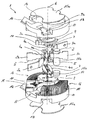
도 1은 회전방식으로 이동가능한 접촉 링크(회전식 링크) 및 2 개의 소호 챔버들을 포함하는 발명에 따른 스위칭 시스템의 분해 도면을 도시한다.
도 2는 회전식 링크를 분해 도면으로 도시한다.
도 3a 및 도 3b는 각각 접촉부들이 폐쇄 및 개방된 스위칭 시스템을 평면도로 도시한다.
도 4는 스위칭 시스템의 자기 엘리먼트의 사시도를 도시한다.
도 5는 조립된 상태의 도 1에 도시된 스위칭 시스템의 사시도를 도시한다.Exemplary embodiments of the invention will be described in more detail below with reference to the drawings.
Figure 1 shows an exploded view of a switching system according to the invention comprising a contact link (rotary link) movable in a rotatable manner and two soho chambers.
Figure 2 shows the rotary link in an exploded view.
Figures 3a and 3b show a top view of a switching system in which the contacts are closed and open, respectively.
Figure 4 shows a perspective view of a magnetic element of a switching system.
Figure 5 shows a perspective view of the switching system shown in Figure 1 in the assembled state.
모든 도면들에서, 상호 대응하는 부분들에는 동일한 참조 기호들이 제공되었다.In all figures, identical reference symbols have been provided for mutually corresponding parts.
도 1 및 도 5는 특히 직류용으로 의도되고, 그리고 바람직하게는 HV 릴레이와 함께, 분해 도면으로 그리고 조립된 상태인 스위칭 시스템(1)을 각각 도시한다. 회로(더욱 상세하게 도시되지 않음)는 스위칭 시스템(1)에 의하여 보호되고, 스위칭 시스템(1)의 2개의 연결부들(2a, 3a)은 전기 케이블들 등과 같은 회로의 또 다른 엘리먼트에 전기적 전도방식으로 연결된다. 회로는 250A의 연속적인 전류, 또는 예를 들어, 또한 50ms 동안 600A의 전류를 전도시킬 수 있다. 연결부들(2a, 3a)에서 존재하는 전압은 정상 동작 동안에 450V와 800V 사이이다.Figures 1 and 5
연결부들(2a, 3a)은 대략 U 형태로 굴곡되어 있는 연결 레일들(2, 3)의 레일 다리(rail limb)들에 의해 형성되고, 연결 레일들은 구부러진 부분 또는 굴곡부의 영역에 고정 접촉부(4a)를 각각 가진다. 접촉 시에는, 각각의 경우에 있어서, 하나의 이동 접촉부(4b)가 각각의 고정 접촉부(4a)와 기계적으로 그리고 전기적으로 접촉하고 있고, 이 접촉부들은 함께 접촉 포인트(4a, 4b)를 각각 형성한다. 연결 레일들(2 및 3)의 각각의 추가적인, 비교적 짧은 레일 다리(2b, 3b)는 비교적 긴 연결 또는 레일 다리들(2a, 3a)과 동일한 방식으로 대략 방사상으로 각각 비슷하게 뻗어있다.The connecting portions 2a and 3a are formed by rail limbs of substantially U-shaped connecting
이동 접촉부들(4b)은 회전축(6)을 중심으로 회전가능한, 구리로 구성된 접촉 링크(5)에 의해 지탱된다. 이를 위하여, 접촉 링크(5)는 양 측부 상에서 각각의 경우에 있어서 하나의 회전식 링크 마운트(7) 내로 삽입된다. 전기적 절연성이며 열적으로 비교적 안정적인 재료로 제조되는 각각의 회전식 링크 마운트(7)는 베어링부(8)에 연결된다. 그러므로, 회전식 링크 마운트(7)는 접촉 링크(5)를 수납하고 베어링부들(8)은 그 사이에 회전식 링크 마운트(7)를 수납한다.The moving
각각의 베어링부(8)는 회전식 링크 마운트(7)로부터 반대 방향으로 실질적으로 중심에서, 이하에서 하우징부로 지칭되는 하우징 커버, 또는 하우징 하프-쉘(half-shell, 10) 내부에서 대응하는 베어링 오목부(9b) 내에 계합하는 베어링 핀(9a)을 가진다. 베어링 핀들(9a) 및 베어링 오목부(9b)는 함께 베어링 포인트를 각각 형성하고, 이 베어링 포인트의 도움으로, 접촉 링크(5)는 회전축(6)을 중심으로 피봇(pivot)될 수 있다. 캠(11)은 각각의 베어링(9a, 9b)에 대하여 편심 방식으로 그 각각의 주변 영역에서 각각의 베어링부(8)에 끼워지고, 캠은 결합 로드(12) 내에 계합한다. 각각의 결합 로드(12)는 각각의 하우징부(10)의 안내 윤곽부(contour) 또는 홈(13) 내부에서 안내되고, 상기 안내 윤곽부는 베어링부(8)로부터 반대 방향이고, 그 결과, 결합 로드(12)의 가로방향 이동은 회전축(6) 중심의 베어링부(8)의 회전으로 귀착된다.Each bearing
각각의 하우징 커버(10)는 각각의 안내 홈(13)과 인접하는 절개부(cutout, 14)를 또한 가진다. 자기 엘리먼트(15)(도 4)의 강철 판(15a)이 각각의 절개부(14) 내에 삽입된다. 강철 판들(15a)의 크기 또는 그 치수들은 이 경우에 있어서, 접촉 링크(5)가 강철 판들(15a)에 의해 커버되도록 되어 있다. 다시 말해서, 강철 판들(15a) 중의 하나가 그 내부에 놓여 있는 각각의 평면상으로의 회전축(6)에 따른 접촉 링크(5)의 각각의 투영은 각각의 강철 판(15a)에 의해 커버된다.Each
2개의 반원형 소호 챔버들(16)은 회전축(6)에 대하여 방사상으로 접촉 링크(5) 주위에 배치된다. 아크 스플리터 판들을 갖지 않는 2개의 영역들(17)(아크 스플리터 판들이 제거된 영역들)은 2개의 소호 챔버들(16) 사이에 배치되고, 연결 레일들(2, 3)은 상기 영역들 내에 배치된다. 각각의 소호 챔버(16)는 회전축(6)에 평행하게 연장되는 복수의 방사상으로 뻗어 있는 아크 스플리터 판들(18)을 가진다. 아크 스플리터 판들(18)은 이와 같이 펼쳐져 있고, 회전축(6)으로부터의 거리가 증가함에 따라, 2개의 인접한 아크 스플리터 판들(17) 사이의 거리가 증가한다. 아크 스플리터 판들(18) 또는 소호 챔버들(16)과, 성형된 연결 레일들(2, 4)은 방사상 방향에서 접촉 링크(5)를 완전히 둘러싸고, 접촉 링크(5)는 소호 챔버들(16)을 따라 베어링부(8)에 의하여 이동가능하다.Two semicircular loops (16) are arranged around the contact link (5) radially with respect to the axis of rotation (6). Two
조립된 상태에서는, 스위칭 시스템(1)이 실질적으로 원통형이고, 강철 판들(15a) 및 하우징 커버들(10)의 부분들이 각각의 기저 영역들을 형성한다. 측면 표면 영역들은 소호 챔버들(16)과, 하우징 커버들(10)의 비슷한 부분들을 포함한다. 자기 엘리먼트(15) 및 결합 로드(12)의 둘 모두뿐만 아니라, 결합 로드(12)와 연계된 캠(11)을 제외하고는, 스위칭 시스템(1)은 회전축(6)에 대하여 실질적으로 회전 대칭이고 회전축(6)이 놓여 있는 지점에 대하여 점대칭(point-symmetrical)이 되도록 설계되어 있다.In the assembled state, the
도 2는 접촉 링크(5), 회전식 링크 마운트들(7) 중의 하나, 및 베어링부들(8) 중의 하나의 분해 예시도를 도시한다. 회전 대칭적인 접촉 링크(5)는 4개의 플러그-인(plug-in) 베벨(bevel)들 및 텅(tongue)들을 포함하고, 각각의 경우에 있어서, 이들 중의 각각의 경우에 있어서 2개는 회전식 링크 마운트(7) 내의 2개의 수납 개방부들 또는 홈들(20) 내로 막혀져서 형태-끼움(form-fitting) 및/또는 가압-끼움(force-fitting) 방식으로 거기에 휴지(rest) 상태로 있다. 회전식 링크 마운트(7)는 접촉 링크(5)로부터 반대 방향인 하부 측부 상에 2개의 안내 핀들(21) 및 2개의 베어링 엘리먼트들(22)을 가지고, 이들 중의 안내 핀들 및 베어링 엘리먼트들은 각각의 경우에 있어서 하나는 가시적이다. 조립된 상태에서, 각각의 안내 핀(21)은 베어링부(8)의 방사상으로 뻗어 있는 슬롯과 유사한(slot-like) 안내 윤곽부(23) 내에 휴지 상태로 있다. 안내 윤곽부(23)의 형상으로 인해, 회전식 링크 마운트(7)는 끼워진 상태에서 방사상 베어링 동작에 따라 베어링부(8)에 대하여 이동될 수 있다. 그러므로, 회전식 링크 마운트(7)와, 그 때문에, 이것에 의해 지탱되는 접촉 링크(5)는 유동적인 방식으로 장착된다.Figure 2 shows an exploded view of one of the
각각의 베어링 엘리먼트(22)는 베어링부(8) 내의 접선방향으로 뻗어있는 굴곡된 또는 곡선의 오목부(24) 내에 휴지 상태로 있다. 절개부(24)의 구성에 의하여, 그리고 베어링부-측 안내 윤곽부들(23) 내의 회전식 링크-측 안내 핀들(21)에 대한 적어도 소량의 동작으로 인해, 회전식 링크 마운트(14)는 베어링부(8)에 관하여 회전축(6)을 중심으로 최대 5°의 각도를 통해 회전 방식으로 이동가능하다.Each bearing
베어링 엘리먼트(22)는 특히, 중심에 슬롯이 형성된다. 판 스프링(leaf spring)의 형태로 구성되며 회전 및 접촉 압력 스프링으로서 작용하는 스프링(26)의 스프링 단부들은 대응하는 슬롯들 또는 노치(notch)들(25) 내에 휴지 상태로 있다. 스프링(26)은 회전축(8)의 영역 내에 배치되어 있는 베어링부(8)의 2개의 상승된 원통형 지지 엘리먼트들(27) 주위에 굴곡되어 있다. 스프링(26)은 접촉 포인트들(4a, 4b)의 폐쇄된 상태에서 바이어스(bias)되어 있고, 이에 따라, 연결 레일들(2, 3) 상에서 접촉 링크(5)의 희망된 또는 요구된 접촉 압력을 생성한다. 접촉 링크(5)의 유동적인 장착과 함께, 스프링(26)은 스위칭 시스템(1)의 스위칭-온(switched-on) 상태에서, 접촉부들(4a, 4b)의 상이한 접촉 부식 시에도, 접촉 압력이 접촉 포인트들(4a, 4b) 사이에서 균일하게 항상 분포되는 것을 보장한다. 베어링부(8)에 대한 회전식 링크 마운트(7)의 이동 시에는, 스프링(26)은 굴곡되고, 이에 따라, 스프링력(spring force)이 발생되고, 이것은 회전식 링크 마운트(7)를 그 원래의 위치로, 이에 따라, 접촉 링크(5)를 폐쇄 상태로 드라이빙한다.The bearing
베어링부(8)에 관한 회전식 링크 마운트(7) 또는 접촉 링크(5)의 유동적인 배치로 인해, 스위칭 시스템(1)의 제조 동안에 비교적 높은 제조 공차들이 허용되는 것이 가능하다. 접촉 위치로부터 회전축(6) 중심의 베어링부(8)의 회전 시에는, 안내 핀들(21)이 베어링부(8)의 안내 윤곽부(23)에 대해 지탱하거나 스프링(26)으로부터 압력이 제거될 때까지, 접촉부들(4a, 4b) 사이의 접촉이 스프링(26)에 의하여 유지된다. 이 상태를 지나는 베어링부(8)의 회전에 의하여, 접촉 포인트들(4a, 4b)은 개방된다.Due to the flexible arrangement of the
도 4는 조립된 자기 엘리먼트(15)의 사시도를 예시한다. 강철 바아(15b)와, 그에 대해 동축인 2개의 영구 자석들(15c)은 2개의 상호 평행한 강철 판들(15a) 사이에 배치된다. 상기 강철 바아 및 상기 영구 자석들은 회전축(8)에 평행하고, 2개의 강철 판들(15a)을 자기적으로 서로 연결한다. 영구 자석들(15c)은 프로세스에서 강철 바아(15b) 및 강철 판들(15a)을 둘 모두 자화시키고, 그러므로, 이 둘은 서로에 부착된다. 그러므로, 자기 엘리먼트(15)를 장착하기 위한 더 이상의 접착제 또는 장착 수단이 요구되지 않는다. 그러나, 안정성을 증가시키기 위해서는, 이들이 또한 접착 방식으로 본딩(bonding)되거나 나사결합(screw)될 수 있다. 2개의 영구 자석들(15c)은, 그 방향이 회전축(8)에 평행인 실질적으로 균질의 자기장(28)이 2개의 강철 판들(15a) 사이에 형성되도록 자화되며 서로에 대해 배치된다.Figure 4 illustrates a perspective view of the assembled
도 3a 및 도 3b는 각각 폐쇄 및 개방 상태인 스위칭 시스템(1)을 도시한다. 접촉 상태에서는, 전류가 연결 레일들(2 및 3), 접촉 포인트들(4a, 4b) 및 접촉 링크(5)를 통해 흐른다. 고정 접촉부들(4a)은 각각의 이동 접촉부들(4b)(도 3a)과 직접 기계적으로 그리고 전기적으로 접촉되어 있다. 회로 내에서의 고장 시에는, 결합 로드들(12)에 의한 베어링부(8)와, 또한 접촉 링크(5)는 회전축(6)을 중심으로 회전되고, 그러므로, 이동 접촉부들(4b)은 연관된 고정 접촉부들(4a)로부터 기계적으로 격리된다. 전류의 레벨 및 전압의 레벨로 인해, 각각의 경우에 있어서 제 1 아크 및 제 2 아크가 상기 접촉부들 사이에 형성된다. 이 경우, 아크들로 인해, 전류는 스위칭 시스템(1)을 통해 계속 흐른다.Figures 3A and 3B show the
자기 엘리먼트(15)에 의해 생성된 자기장(28)은 아크들에 작용하는 로렌쯔의 힘을 유발하고, 그 결과, 상기 아크들은 그 전파 방향에 대해 수직으로 그리고 자기장(28)에 수직으로 편향된다. 그러므로, 아크들은 비교적 짧은 시간 기간 동안에 접촉 포인트들(4a, 4b)로부터 멀어지도록 이동되고, 이것은 상기 접촉 포인트들의 접촉부들을 과도한 부하 및 손상으로부터 보호한다. 아크들의 정렬로 인해, 상기 아크들은 자기장(28)에 의하여 동일한 방향으로 그리고 동일한 소호 챔버(16)를 향해 이동된다. 회전축(6) 중심의 접촉 링크(5)의 계속된 회전과, 회전축(6)으로부터의 각각의 아크의 증가하는 거리 둘 모두로 인해, 제 1 아크의 길이는 연장된다. 다른 한편으로, 다른 아크는 회전축(6)을 향해 이동되고, 이러한 이유로, 그 길이는 비교적 적게 변화한다. 아크들 각각의 길이가 증가할수록, 아크들을 유지하기 위해 요구되는 전압은 증가한다. 이 전압이 스위칭 시스템(1)에서 이미 존재하는 전압을 초과하는 경우, 아크들은 소호된다. 스위칭 시스템(1)을 통한 전류 흐름은 이에 따라 중단된다.The
각각의 아크는 자기장(28)에 의하여 소호 챔버(16)의 대응하는 아크 스플리터 스택(arc splitter stack) 내로 드라이빙된다. 거기에서, 아크는 개별적인 아크 스플리터 판들(18) 사이에서 다수의 부분적인 아크들로 분할된다. 스위칭 시스템(1)을 통한 전류 흐름을 유지하기 위해 요구되는 전압은 이에 따라 다시 증가된다. 자기장(28)에 의하여, 제 2 아크는 제 1 아크로부터 반대로 향하는 접촉 링크(5)의 그 측부로부터 제 1 아크를 갖는 소호 챔버(16)가 그 위에 배치되는 스위칭 시스템(1)의 그 측부로 이동된다. 제 2 아크는 자기장(28)에 의하여 이 소호 챔버(16) 상으로 방사상으로 외부를 향해 가속된다. 회전으로 인해, 제 2 아크의 길이는 단축될 수 있거나 일정하게 유지될 수 있다. 방사상 방향으로의 이동은 그 길의 확대로 귀착된다. 이 2개의 효과들은 제 2 아크의 길이가 여전히 실질적으로 일정하게 되는 것으로 귀착되고, 축(6)의 레벨이 초과될 경우에는, 제 2 아크가 상당히 넓어진다.Each arc is driven by a
접촉 링크(5)가 더 회전될 수 없는 경우, 제 2 아크는 회전으로 인해 더 이상 단축되지 않는다. 대신에, 회전축(6)으로부터의 거리가 증가함에 따라 그 길이가 증가한다. 각각의 소호 챔버(16)에서는, 제 2 아크가 개별적인 아크 스플리터 판들(18) 사이의 다수의 부분적인 아크들로 비슷하게 분할된다. 이것과, 자기장(28)에 의한 방사상으로 외부를 향한 부분적인 아크들의 이동과, 이에 따른 각각의 부분적인 아크의 길이의 확대는 개별적인 부분적인 아크들의 소호로 귀착된다. 스위칭 시스템(1)을 통한 전류 흐름은 이에 따라 중단되고, 회로의 컴포넌트들은 과부하로부터 보호된다.If the
발명은 상기 설명된 예시적인 실시예로 제한되지 않는다. 대신에, 발명의 다른 변형들이 발명의 요지로부터 이탈하지 않으면서 당해 분야의 당업자에 의해 이것으로부터 또한 유도될 수 있다. 특히, 부가적으로, 예시적인 실시예와 관련하여 설명된 모든 개별적인 특징들이 발명의 요지로부터 이탈하지 않으면서 또 다른 방식으로 서로 또한 조합될 수 있다.The invention is not limited to the exemplary embodiments described above. Instead, other modifications of the invention may be derived from this by those skilled in the art without departing from the gist of the invention. In particular, all of the individual features described in connection with the exemplary embodiments may also be combined with each other in yet another manner without departing from the gist of the invention.
1 : 스위칭 시스템 14 : 절개부
2 : 연결 레일 15 : 자기 엘리먼트
2a : 다리/연결부 15a : 강철 판
2b : 레일 다리 15b : 강철 바아
3 : 연결 레일 15c : 영구 자석
3a : 다리/연결부 16 : 소호 챔버
3b : 레일 다리 17 : 판들이 제거된 영역
4a : 이동 접촉부 18 : 아크 스플리터 판
4b : 고정 접촉부 19 : 플러그-인 베벨/텅
5 : 접촉 링크 20 : 수납 개방부/홈
6 : 회전축 21 : 안내 핀
7 : 회전식 링크 마운트 22 : 베어링 엘리먼트
8 : 베어링부 23 : 안내 윤곽부
9a : 베어링 핀 24 : 절개부
9b : 베어링 오목부 25 : 노치/슬롯
10 : 하우징 커버 26 : 스프링
11 : 캠 27 : 지지 엘리먼트
12 : 결합 로드 28 : 자기장
13 : 안내 윤곽부/홈1: Switching system 14:
2: connecting rail 15: magnetic element
2a: leg /
2b: rail bridge 15b: steel bar
3: connecting
3a: leg / joint 16: SOHO chamber
3b: rail leg 17: area where plates are removed
4a: moving contact 18: arc splitter plate
4b: fixed contact 19: plug-in bevel / tongue
5: contact link 20: storage opening / groove
6: rotation shaft 21: guide pin
7: Rotary link mount 22: Bearing element
8: bearing part 23: guide contour part
9a: Bearing pin 24:
9b: bearing recess 25: notch / slot
10: housing cover 26: spring
11: cam 27: support element
12: coupling rod 28: magnetic field
13: guide contour / groove
Claims (14)
2개의 접촉 포인트들(4a, 4b) 사이에서 회전축(6)을 중심으로 회전 가능하게 이동가능하도록 배치된 접촉 링크(5)를 포함하고, 접촉 포인트들(4a, 4b)이 개방될 때에 생성된 아크를 소호 챔버(16) 내로 드라이빙(driving)하기 위한 자기 엘리먼트(15)를 포함하는,
스위칭 시스템(1).In particular, as a switching system (1) for a relay or a contactor,
And a contact link 5 disposed between the two contact points 4a and 4b so as to be rotatably movable about a rotational axis 6 and which is arranged to be rotatable about the rotational axis 6, Comprising a magnetic element (15) for driving an arc into a soho chamber (16)
Switching system (1).
상기 접촉 링크(5)는 유동적인 방식으로 장착되는,
스위칭 시스템(1).The method according to claim 1,
The contact link (5) is mounted in a floating manner,
Switching system (1).
상기 접촉 링크(5)는 특히, 베어링 동작으로, 회전식 링크 마운트(7)에 의하여 방사상으로 이동가능한 방식으로, 및/또는 베어링부(8)에 대해 회전에 의해 이동가능한 방식으로 베어링부(8)에 연결되는,
스위칭 시스템(1).3. The method according to claim 1 or 2,
The contact link 5 is particularly suitable for bearing operation in such a way that it can be moved radially by means of a rotary link mount 7 and / or by rotation relative to the bearing part 8, Lt; / RTI >
Switching system (1).
상기 회전식 링크 마운트(7)는 상기 베어링부(8)의 적어도 하나의 방사상 안내 윤곽부(23) 내에 안내되는,
스위칭 시스템(1).The method of claim 3,
The rotary link mount (7) is guided in at least one radial guiding portion (23) of the bearing portion (8)
Switching system (1).
상기 접촉 링크(5)는 특히, 상기 회전식 링크 마운트(7)를 통해, 접촉 포인트들(4a, 4b)이 폐쇄될 때 바이어스된 적어도 하나의 스프링(26)에 의하여 상기 베어링부(8)에 결합되는,
스위칭 시스템(1).The method according to claim 3 or 4,
The contact link 5 is in particular connected to the bearing part 8 by means of at least one spring 26 biased when the contact points 4a and 4b are closed via the rotary link mount 7, felled,
Switching system (1).
베어링 엘리먼트들(22)이 바람직하게는 회전식 링크 마운트(7) 상에 일체로 형성되어 있는 상기 회전식 링크 마운트(7)는, 상기 베어링부(8) 내의 접선방향으로 뻗어 있는 절개부들(24) 내에 휴지 상태로 있고, 상기 베어링 엘리먼트들(22)은 스프링-단부 측 상에 상기 스프링(26)을 수납하는,
스위칭 시스템(1).6. The method of claim 5,
The rotary link mount 7, in which the bearing elements 22 are preferably formed integrally on the rotary link mount 7, is provided within the tangentially extending cuts 24 in the bearing portion 8, Wherein the bearing elements (22) are configured to receive the spring (26) on a spring-
Switching system (1).
상기 스프링(26)은 상기 베어링부(8)의 2개의 지지 엘리먼트들(27) 사이에 위치되는,
스위칭 시스템(1).The method according to claim 5 or 6,
The spring (26) is located between two support elements (27) of the bearing part (8)
Switching system (1).
상기 지지 엘리먼트들(27)은 상기 안내 윤곽부들(23) 및/또는 상기 베어링부(8)의 상기 절개부들(24) 사이에 연달아 배치되고, 상기 스프링(26)은 상기 지지 엘리먼트들(27) 사이에 대략 z 형태로 굴곡되는,
스위칭 시스템(1).8. The method of claim 7,
The support elements 27 are arranged in series between the guide contours 23 and / or the cutouts 24 of the bearing part 8 and the spring 26 is supported by the support elements 27, Lt; RTI ID = 0.0 > z < / RTI &
Switching system (1).
상기 소호 챔버(16)는 다수의 방사상으로 뻗어 있는 아크 스플리터 판들(18)을 포함하는,
스위칭 시스템(1).9. The method according to any one of claims 1 to 8,
The SOHO chamber (16) includes a plurality of radially extending arc splitter plates (18)
Switching system (1).
상기 접촉 포인트들(4a, 4b)은 상기 접촉 링크(5)에 의해 지탱되는 이동 접촉부들(4b)과, 상기 이동 접촉부들(4b)과 상호작용하는 고정 접촉부들(4a)로 형성되고, 상기 접촉부들은 각각의 경우에 있어서 굴곡된 연결 레일(2, 3), 특히 U 형태로 굴곡된 연결 레일 상에 배치되는,
스위칭 시스템(1).10. The method according to any one of claims 1 to 9,
The contact points 4a and 4b are formed by movable contacts 4b supported by the contact link 5 and fixed contacts 4a interacting with the movable contacts 4b, The contacts are in each case bent on the connecting rails 2, 3, in particular on the connecting rail curved in U-shape,
Switching system (1).
임의의 아크 스플리터 판들을 갖지 않는 2개의 영역들(17)은 상기 아크 스플리터 판들(18) 사이에, 바람직하게는 서로 대향하도록 제공되고, 상기 영역들에서는, 상기 연결 레일들(2, 3)이, 특히 적어도 대략 방사상 레일 프로파일로 삽입되는,
스위칭 시스템(1).10. The method of claim 9,
Two areas 17 without any arc splitter plates are provided between the arc splitter plates 18, preferably facing one another, in which the connecting rails 2, 3 , Especially at least about the radial rail profile,
Switching system (1).
상기 회전축(6)에 대하여 실질적으로 점 대칭적 및/또는 회전 대칭적인 설계인,
스위칭 시스템(1).12. The method according to any one of claims 1 to 11,
Which is a substantially point symmetrical and / or rotationally symmetrical design with respect to said rotary shaft (6)
Switching system (1).
상기 자기 엘리먼트(15)는, 상기 회전축(6)에 실질적으로 수직으로 배치되며 상기 접촉 링크(5)를 적어도 부분적으로 커버하는, 서로 자기적으로 접촉 상태인 적어도 하나의 영구 자석(15c) 및 2개의 강철 판들(15a)을 포함하는,
스위칭 시스템(1).13. The method according to any one of claims 1 to 12,
The magnetic element 15 comprises at least one permanent magnet 15c and two permanent magnets 15a and 15b which are magnetically in contact with each other and which are arranged substantially perpendicular to the axis of rotation 6 and at least partly covering the contact link 5, Lt; RTI ID = 0.0 > 15a, < / RTI &
Switching system (1).
상기 접촉 링크(5)의 상기 회전축(6)에 평행한 자기장(28)인,
스위칭 시스템(1).14. The method according to any one of claims 1 to 13,
Which is a magnetic field (28) parallel to the rotation axis (6) of the contact link (5)
Switching system (1).
Applications Claiming Priority (3)
| Application Number | Priority Date | Filing Date | Title |
|---|---|---|---|
| DE102011118418.3A DE102011118418B4 (en) | 2011-11-12 | 2011-11-12 | switching system |
| DE102011118418.3 | 2011-11-12 | ||
| PCT/EP2012/003457 WO2013068057A1 (en) | 2011-11-12 | 2012-08-14 | Switching system |
Publications (2)
| Publication Number | Publication Date |
|---|---|
| KR20140096056A true KR20140096056A (en) | 2014-08-04 |
| KR101823462B1 KR101823462B1 (en) | 2018-01-30 |
Family
ID=46801413
Family Applications (1)
| Application Number | Title | Priority Date | Filing Date |
|---|---|---|---|
| KR1020147012722A KR101823462B1 (en) | 2011-11-12 | 2012-08-14 | Switching system |
Country Status (12)
| Country | Link |
|---|---|
| US (1) | US9431197B2 (en) |
| EP (1) | EP2777057B1 (en) |
| KR (1) | KR101823462B1 (en) |
| CN (1) | CN103930962B (en) |
| BR (1) | BR112014011257A2 (en) |
| CA (1) | CA2855914C (en) |
| DE (2) | DE102011118418B4 (en) |
| ES (1) | ES2558789T3 (en) |
| IN (1) | IN2014CN03360A (en) |
| MX (1) | MX2014005655A (en) |
| RU (1) | RU2570169C1 (en) |
| WO (1) | WO2013068057A1 (en) |
Cited By (1)
| Publication number | Priority date | Publication date | Assignee | Title |
|---|---|---|---|---|
| KR20200141499A (en) * | 2018-04-16 | 2020-12-18 | 타이코 일렉트로닉스 (선전) 코. 엘티디. | relay |
Families Citing this family (14)
| Publication number | Priority date | Publication date | Assignee | Title |
|---|---|---|---|---|
| DE202015009305U1 (en) * | 2015-08-10 | 2017-01-30 | Ellenberger & Poensgen Gmbh | switching system |
| DE102016123283A1 (en) * | 2016-12-01 | 2018-06-07 | Innofas Gmbh | Device for separating a vehicle electrical system from an energy source |
| CN108122719A (en) * | 2017-12-20 | 2018-06-05 | 张正宇 | A kind of helical compression types arc-extinguishing mechanism of power circuit breaker |
| GB2580174B (en) * | 2018-12-23 | 2022-10-26 | Secheron Hasler Uk Ltd | An electrical switch and an electrical switch system |
| CN109950095B (en) * | 2019-02-26 | 2020-07-31 | 哈尔滨工业大学 | Arc extinguishing structure for relay and manufacturing method thereof |
| CN109920669A (en) * | 2019-04-10 | 2019-06-21 | 北京北元电器有限公司 | A kind of arc-control device and arc-suppressing method with monoblock type arc insulating cover |
| KR102558812B1 (en) * | 2020-03-13 | 2023-07-24 | 엘에스일렉트릭(주) | Arc extinguish part and air circuit breaker include the same |
| KR102556750B1 (en) * | 2020-03-20 | 2023-07-18 | 엘에스일렉트릭(주) | Arc extinguishing assembly and circuit breaker having the same |
| ES2956873T3 (en) * | 2020-04-28 | 2023-12-29 | Abb Schweiz Ag | New design of divider plate support for application in medium voltage gas insulated load disconnect switches |
| EP3905292A1 (en) * | 2020-04-28 | 2021-11-03 | ABB Schweiz AG | New design of splitter plate holder for application in medium voltage gas insulated load break switches |
| EP3985700B1 (en) | 2020-10-14 | 2023-08-09 | ABB Schweiz AG | Electric switch |
| FR3123143A1 (en) * | 2021-05-21 | 2022-11-25 | Socomec | Electric cut-off module equipped with a magnetic blow-out device and electric cut-off device comprising such a module |
| KR102542180B1 (en) * | 2022-03-30 | 2023-06-14 | 오성기전 주식회사 | Arc extinguish device of DC circuit breaker |
| EP4297058A1 (en) * | 2022-05-27 | 2023-12-27 | Huawei Digital Power Technologies Co., Ltd. | Power supply system and switch unit |
Family Cites Families (16)
| Publication number | Priority date | Publication date | Assignee | Title |
|---|---|---|---|---|
| FR2648952B1 (en) * | 1989-06-26 | 1991-09-13 | Merlin Gerin | LIMITING CIRCUIT BREAKER HAVING AN ELECTROMAGNETIC EFFECT CONTACT DELAY RETARDER |
| RU2074438C1 (en) * | 1994-10-14 | 1997-02-27 | Всероссийский электротехнический институт им.В.И.Ленина | Electromagnetic drive for switches |
| FR2762710B1 (en) * | 1997-04-25 | 2003-05-30 | Soule Materiel Electr | ELECTRICAL SHUTDOWN DEVICE FOR LOW AND HIGH VOLTAGE |
| DE10061394B4 (en) * | 2000-12-09 | 2008-10-09 | Moeller Gmbh | Switching device with floating, double interrupting rotary contact |
| US6791440B2 (en) * | 2002-08-02 | 2004-09-14 | General Electric Company | Apparatus for electrically isolating circuit breaker rotor components |
| WO2006133726A1 (en) * | 2005-06-16 | 2006-12-21 | Secheron S.A. | Blow-out device for an electromechanical dc circuit breaker |
| DE102006035844B4 (en) * | 2006-08-01 | 2008-06-19 | Schaltbau Gmbh | Contactor for DC and AC operation |
| CN200972833Y (en) * | 2006-10-25 | 2007-11-07 | 浙江正泰电器股份有限公司 | Automatic changover switch with quick arc extinguishing |
| DE102007040164A1 (en) * | 2007-08-21 | 2009-02-26 | Siemens Ag | Low voltage switching device e.g. power switch, for three-pole switching device arrangement, has rotary contact system arranged such that contact bridge is axially lifted in case of overvoltage or short circuit |
| JP4468431B2 (en) * | 2007-11-28 | 2010-05-26 | カルソニックカンセイ株式会社 | Multi-directional operation switch device |
| DE102008009439A1 (en) * | 2008-02-14 | 2009-08-20 | Siemens Aktiengesellschaft | Electrical circuit-breaker, has contact connected with terminals by paths running parallel to fixed pieces at side turned away from movable pieces in area of fixed pieces, where current flows in area along certain direction |
| US7683287B2 (en) * | 2008-05-08 | 2010-03-23 | Cooper Technologies Company | Multiple arc chamber assemblies for a fault interrupter and load break switch |
| DE102008037967A1 (en) * | 2008-08-13 | 2010-02-18 | Siemens Aktiengesellschaft | Rotary contact system for power switching device, has spring gripping molded inner contour of recess in spring loaded condition such that arms are provided with slack point characteristic during rotational motion relative to shaft segments |
| DE102008039187B4 (en) * | 2008-08-20 | 2019-06-19 | Siemens Aktiengesellschaft | Circuit breaker, especially for low voltage |
| DE102008049442B4 (en) * | 2008-09-29 | 2015-02-19 | Siemens Aktiengesellschaft | Rotary contact system for a switching device, in particular for a power switching device, with a radially applied from the inside closing torque |
| DE102009013337B4 (en) | 2009-03-16 | 2011-01-27 | Schaltbau Gmbh | Arc-resistant contactor |
-
2011
- 2011-11-12 DE DE102011118418.3A patent/DE102011118418B4/en not_active Expired - Fee Related
-
2012
- 2012-08-14 MX MX2014005655A patent/MX2014005655A/en active IP Right Grant
- 2012-08-14 CA CA2855914A patent/CA2855914C/en not_active Expired - Fee Related
- 2012-08-14 CN CN201280055525.4A patent/CN103930962B/en active Active
- 2012-08-14 RU RU2014123700/07A patent/RU2570169C1/en not_active IP Right Cessation
- 2012-08-14 BR BR112014011257A patent/BR112014011257A2/en not_active Application Discontinuation
- 2012-08-14 ES ES12756088.6T patent/ES2558789T3/en active Active
- 2012-08-14 KR KR1020147012722A patent/KR101823462B1/en active IP Right Grant
- 2012-08-14 WO PCT/EP2012/003457 patent/WO2013068057A1/en active Application Filing
- 2012-08-14 DE DE202012013255.5U patent/DE202012013255U1/en not_active Expired - Lifetime
- 2012-08-14 EP EP12756088.6A patent/EP2777057B1/en active Active
-
2014
- 2014-05-05 IN IN3360CHN2014 patent/IN2014CN03360A/en unknown
- 2014-05-12 US US14/274,903 patent/US9431197B2/en active Active
Cited By (2)
| Publication number | Priority date | Publication date | Assignee | Title |
|---|---|---|---|---|
| KR20200141499A (en) * | 2018-04-16 | 2020-12-18 | 타이코 일렉트로닉스 (선전) 코. 엘티디. | relay |
| US11942295B2 (en) | 2018-04-16 | 2024-03-26 | Tyco Electronics (Shenzhen) Co., Ltd. | Relay |
Also Published As
| Publication number | Publication date |
|---|---|
| RU2570169C1 (en) | 2015-12-10 |
| MX2014005655A (en) | 2014-08-22 |
| DE102011118418B4 (en) | 2015-07-16 |
| KR101823462B1 (en) | 2018-01-30 |
| ES2558789T3 (en) | 2016-02-08 |
| DE102011118418A1 (en) | 2013-05-16 |
| CA2855914A1 (en) | 2013-05-16 |
| CN103930962A (en) | 2014-07-16 |
| DE202012013255U1 (en) | 2015-09-14 |
| EP2777057B1 (en) | 2015-10-28 |
| US9431197B2 (en) | 2016-08-30 |
| IN2014CN03360A (en) | 2015-07-03 |
| WO2013068057A1 (en) | 2013-05-16 |
| CA2855914C (en) | 2019-04-23 |
| US20140246403A1 (en) | 2014-09-04 |
| CN103930962B (en) | 2016-12-21 |
| EP2777057A1 (en) | 2014-09-17 |
| BR112014011257A2 (en) | 2017-04-25 |
Similar Documents
| Publication | Publication Date | Title |
|---|---|---|
| KR101823462B1 (en) | Switching system | |
| AU2006205625B2 (en) | Blow open moving contact assembly for electric power switching apparatus with a very high current interruption rating | |
| EP2197009B1 (en) | Contact bridge with blow magnets | |
| EP2348519B1 (en) | Movable contactor assembly for a current limiting type molded case circuit breaker | |
| US8039770B2 (en) | Movable contact arm and crossbar assembly and electrical switching apparatus employing the same | |
| US6064024A (en) | Magnetic enhanced arc extinguisher for switching assemblies having rotatable permanent magnets in housings mounted to fixed contacts | |
| US20010040147A1 (en) | Cassette assembly with rejection features | |
| US10854414B2 (en) | High voltage electrical disconnect device with magnetic arc deflection assembly | |
| KR100701775B1 (en) | Moving contact device in air circuit breaker | |
| CN114097055A (en) | Relay with a movable contact | |
| US6989501B2 (en) | Current limiting circuit breaker | |
| US7863537B2 (en) | Gassing insulator assembly, and conductor assembly and electrical switching apparatus employing the same | |
| KR20210007390A (en) | Arc Extinguishing Unit of Molded Case Circuit Breaker | |
| CN101901727B (en) | Electrical switchgear and adjustable carrier assembly thereof | |
| CN110678949B (en) | Switching device with contact cover | |
| KR20100079919A (en) | Elastic pressing unit and molded case circuit breaker having the same | |
| JP7248955B2 (en) | circuit breaker | |
| KR101100705B1 (en) | Vacuum circuit breaker having mechanism for absorbing impact on mold housing due to electro magnetic force applied by adjacent busbar type terminals |
Legal Events
| Date | Code | Title | Description |
|---|---|---|---|
| A201 | Request for examination | ||
| E902 | Notification of reason for refusal | ||
| E701 | Decision to grant or registration of patent right | ||
| GRNT | Written decision to grant |