EP2777057B1 - Switching system - Google Patents
Switching system Download PDFInfo
- Publication number
- EP2777057B1 EP2777057B1 EP12756088.6A EP12756088A EP2777057B1 EP 2777057 B1 EP2777057 B1 EP 2777057B1 EP 12756088 A EP12756088 A EP 12756088A EP 2777057 B1 EP2777057 B1 EP 2777057B1
- Authority
- EP
- European Patent Office
- Prior art keywords
- switching system
- contact
- bridge
- bearing part
- rotation
- Prior art date
- Legal status (The legal status is an assumption and is not a legal conclusion. Google has not performed a legal analysis and makes no representation as to the accuracy of the status listed.)
- Active
Links
Images


Classifications
-
- H—ELECTRICITY
- H01—ELECTRIC ELEMENTS
- H01H—ELECTRIC SWITCHES; RELAYS; SELECTORS; EMERGENCY PROTECTIVE DEVICES
- H01H33/00—High-tension or heavy-current switches with arc-extinguishing or arc-preventing means
- H01H33/02—Details
- H01H33/04—Means for extinguishing or preventing arc between current-carrying parts
- H01H33/18—Means for extinguishing or preventing arc between current-carrying parts using blow-out magnet
- H01H33/182—Means for extinguishing or preventing arc between current-carrying parts using blow-out magnet using permanent magnets
-
- H—ELECTRICITY
- H01—ELECTRIC ELEMENTS
- H01H—ELECTRIC SWITCHES; RELAYS; SELECTORS; EMERGENCY PROTECTIVE DEVICES
- H01H1/00—Contacts
- H01H1/12—Contacts characterised by the manner in which co-operating contacts engage
- H01H1/14—Contacts characterised by the manner in which co-operating contacts engage by abutting
- H01H1/20—Bridging contacts
- H01H1/2041—Rotating bridge
-
- H—ELECTRICITY
- H01—ELECTRIC ELEMENTS
- H01H—ELECTRIC SWITCHES; RELAYS; SELECTORS; EMERGENCY PROTECTIVE DEVICES
- H01H1/00—Contacts
- H01H1/12—Contacts characterised by the manner in which co-operating contacts engage
- H01H1/14—Contacts characterised by the manner in which co-operating contacts engage by abutting
- H01H1/20—Bridging contacts
-
- H—ELECTRICITY
- H01—ELECTRIC ELEMENTS
- H01H—ELECTRIC SWITCHES; RELAYS; SELECTORS; EMERGENCY PROTECTIVE DEVICES
- H01H50/00—Details of electromagnetic relays
- H01H50/54—Contact arrangements
-
- H—ELECTRICITY
- H01—ELECTRIC ELEMENTS
- H01H—ELECTRIC SWITCHES; RELAYS; SELECTORS; EMERGENCY PROTECTIVE DEVICES
- H01H9/00—Details of switching devices, not covered by groups H01H1/00 - H01H7/00
- H01H9/30—Means for extinguishing or preventing arc between current-carrying parts
- H01H9/34—Stationary parts for restricting or subdividing the arc, e.g. barrier plate
- H01H9/36—Metal parts
-
- H—ELECTRICITY
- H01—ELECTRIC ELEMENTS
- H01H—ELECTRIC SWITCHES; RELAYS; SELECTORS; EMERGENCY PROTECTIVE DEVICES
- H01H9/00—Details of switching devices, not covered by groups H01H1/00 - H01H7/00
- H01H9/30—Means for extinguishing or preventing arc between current-carrying parts
- H01H9/44—Means for extinguishing or preventing arc between current-carrying parts using blow-out magnet
- H01H9/443—Means for extinguishing or preventing arc between current-carrying parts using blow-out magnet using permanent magnets
Definitions
- the invention relates to a switching system with a movable contact bridge between two contact points according to the preamble of claim 1.
- a switching system is for example from the DE 10 2008 009 439 A1 and from the US 2004/0021536 A1 known.
- the switching system is provided in particular for high DC voltages, preferably for an HV (DC) relay (high voltage direct current) or for a contactor.
- HV DC
- an electrical interruption device for high DC voltages with a rotary contact bridge and with a magnetic field source which is designed to extend the between the movable and the immobile contact in the opening phase forming arc transverse to the plane of movement and thus parallel to the axis of rotation of the rotary contact.
- the magnetic source generates a magnetic field with respect to the Rotary axis of the rotary contact radial orientation.
- the invention has for its object to provide an improved switching system with a movable between two contact points contact bridge.
- the switching system should, preferably in conjunction with a switch in the form of a relay or contactor, for high DC voltages of z. B. at least 450V and for carrying and separating a continuous current of z. B. at least 250A be suitable.
- the switching system has two contact points and a movable contact bridge arranged therebetween.
- the contact points are thus electrically connected in series and are each formed by a fixed contact and a moving contact, which serve to conduct current, wherein the respective moving contact with the contact bridge is firmly connected and is moved with this.
- the fixed contacts are arranged on approximately U-shaped bent connection rails.
- the contact bridge is rotatable about an axis of rotation, wherein by means of a rotation of the contact bridge about the axis of rotation, the switching system is placed in either a conductive or a non-conductive state.
- the contact points are opened or closed as a result of a rotational movement of the contact bridge, also referred to below as a rotating bridge.
- the axis of rotation is preferably arranged centrally to the contact bridge.
- the contact bridge made of copper or other, electrical current highly conductive material.
- the contacts of the contact points and the connection bars of the fixed contacts suitably consist of the same material as the contact bridge, preferably of copper.
- the arc is transformed by means of the magnetic field of a magnetic Elements driven into a quenching chamber.
- the magnetic field generated by the magnetic element is parallel to the axis of rotation of the contact bridge. In this way, the resulting arc when opening the contact points arc is driven in the radial direction. Any components of the circuit breaker that connect to the contact points along the rotation axis are protected and are not damaged by the arc. In particular, the bearing part and / or the iron sheets of the magnetic element are not detected by the arc.
- the magnetic field is at least partially perpendicular to the propagation direction of the respective arc, by means of which a Lorentz force is exerted on the respective arc.
- the magnetic field within the scarf system is substantially constant.
- the electrical voltage required to maintain the arc is suitably increased to a value which is above the voltage applied to the switching system.
- the switching system is operated in particular by means of direct current, wherein an electrical current flows between the 2A and 500A via its rotary bridge.
- the electrical current is 250A, by means of which the switching system is permanently operated.
- the voltage applied to the switching system is between 30V and 1000V, for example between 450V and 800V.
- the contact bridge is radially movable and / or rotatably connected to a bearing part.
- the connection is suitably indirectly via a rotary bridge support, on which the contact bridge is held.
- the bearing part is in this case rotatable about the axis of rotation, while the rotating bridge carrier is guided in at least one, preferably in two radial, slot-like guide contours of the bearing part.
- two bearing parts and two rotary bridge support are provided between which the contact bridge rests or is held.
- a rotation of the or each bearing part about the axis of rotation causes a transition of the switching system from the closed to the open and thus from the conducting to the non-conducting state.
- the or each rotary bridge carrier is in this case connected rotatably to the bearing part and expediently has a radial bearing clearance relative to the respective bearing part.
- the position of the rotary bridge carrier and thus in particular the position of the contact bridge are thus variable relative to the bearing part and to the axis of rotation.
- the rotary bridge carrier is therefore preferably floating with respect to the bearing part, so it can be transversely or tangentially spent in relation to the bearing part.
- the mobility is comparatively low.
- the rotational mobility of the rotary bridge carrier to the bearing part is smaller than the rotational mobility of the bearing part with respect to the fixed contacts. In this way, it is possible to control comparatively large manufacturing tolerances in the manufacture of the circuit breaker, while still ensuring safe operation.
- the service life of the circuit breaker is increased because changes in the contacts due to burn or contamination can be compensated by means of the floating suspension.
- a permanent function of the contact bridge which is suitably accommodated by the two electrically insulating and thermally particularly stable rotating bridge carriers, as a result of arranged only indirectly on a rigid axis contact bridge achieved by these is preferably coupled on both sides, each with a rotatable bearing part.
- the coupling is suitably via, preferably on both sides, one spring each.
- the spring is in closed contact points of the switching system - ie in the on state - tensioned (biased) and thus produces a particularly effective contact pressure of the moving contacts on the fixed contacts.
- This spring-loaded floating mounting ensures that even with different contact erosion at the contact points of the contact pressure is always evenly distributed to both contact points and the contacts there.
- An additional realized reserve of the spring force of the or each spring is particularly useful for Abbrandkompensation.
- the springs also referred to below as contact pressure springs, contribute to the acceleration of the contact bridge.
- the radial mobility of the contact bridge with respect to the bearing part is preferably realized in that the respective rotary bridge carrier in at least one, is preferably guided in two radial guide contours of the bearing part.
- bearing elements take on the spring ends of the respective contact pressure spring. These bearing elements are or engage in recesses of the bearing part.
- the recesses are circular arc-shaped and take virtually no leadership function for the rotating bridge carrier in order to avoid overdetermination and thus jamming of the movable rotating bridge carrier relative to the bearing part.
- the respective spring is positioned between two support elements of the bearing part.
- the expediently cylindrical support elements are arranged in the region of the axis of rotation of the bearing part and thus in this respect centrally one behind the other between the guide contours and possibly between the recesses of the bearing part.
- the respective spring which rests between the two preferably integrally formed on the respective bearing part support elements, is bent in this area approximately z-shaped.
- the quenching chamber has a number of radially extending quenching plates.
- the quenching plates are arranged fan-shaped, wherein the distance between two adjacent quenching plates is increased with increasing distance to the axis of rotation.
- two groups of these fan-like arranged quenching plates are formed, wherein between these splitter plate groups are formed on opposite sides free of sheet metal areas.
- a U-shaped connecting rail is preferably arranged in each case and expediently fitted in a radially extending manner.
- the respective connecting rail carries one of the fixed contacts, which form the two contact points together with the moving contacts carried by the contact bridge.
- the voltage needed to maintain an arc formed between the quenching plates increases with increasing distance of the arc from the axis of rotation.
- the resulting at an operating voltage and driven into the quenching arc therefore breaks down when the arc far enough into the quenching chamber and from the axis of rotation is moved away.
- the movement is expediently also carried out by means of the magnetic element. In this way the arc is extinguished.
- the switching system is constructed substantially point- and / or rotationally symmetrical to the axis of rotation.
- the circuit breaker comprises two extinguishing chambers. Due to this construction, the switching system can be safely operated in both current directions, with one of the extinguishing chambers extinguishing the arc which arises during operation in one of the current directions when opening the contact points. In particular, during installation of the switching system in DC operation, an orientation of the circuit breaker must be disregarded.
- the magnetic element has two iron sheets which essentially cover the contact bridge and are arranged such that the axis of rotation is perpendicular to the latter.
- the contact bridge is located in particular between the two sheets. The contact bridge is thus rotatably arranged without one of the sheets restricting this mobility.
- At least one permanent magnet is in magnetic contact. It is expediently the respective permanent magnet either directly in mechanical contact with the sheets or indirectly via another ferromagnetic element, such as an iron rod.
- the permanent magnet magnetizes the sheets such that a substantially constant magnetic field is formed between them. This magnetic field passes through the contact bridge and drives the resulting arcs at an opening of the contact points in the quenching chamber.
- the magnetic element is not rotationally symmetrical, but arranged eccentrically to the axis of rotation at a certain position.
- connection of the contact bridge of the switching system to the bearing part can also be independent of the magnetic element and the quenching chamber. Rather, it is considered as an independent invention.
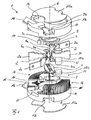
- FIGS. 1 and 5 is shown in particular for DC and preferably provided in conjunction with a HV relay switching system 1 in an exploded view or assembled state.
- a not further shown circuit is hedged, wherein two terminals 2a, 3a of the switching system 1 with other elements of the circuit, such as electric cables or the like, are electrically connected.
- the circuit can provide a permanent electrical current of 250A or z. B. also carry a current of 600A for 50ms.
- the electrical voltage, which is applied to the terminals 2a, 3a, in normal operation is between 450V and 800V.
- the terminals 2a, 3a are formed by rail legs of approximately U-shaped bent connecting rails 2, 3, each having a fixed contact 4a in the region of the bend or bend.
- each fixed contact 4a is in each case a moving contact 4b in mechanical and electrical contact, which together form a contact point 4a, 4b.
- the respective further, comparatively short rail limbs 2 b, 3 b of the connecting rails 2 and 3, as well as the comparatively long connecting upper rail limbs 2 a, 3 a, extend approximately radially.
- the moving contacts 4b are supported by a contact bridge 5 made of copper, which is rotatable about a rotation axis 6.
- the contact bridge 5 is inserted on both sides in each case a rotary bridge carrier 7.
- Each rotating bridge carrier 7, which is made of an electrically insulating and thermally comparatively stable material, is connected to a bearing part 8.
- the rotating bridge support 7 take the contact bridge 5 and the bearing parts 8, the rotary bridge carrier 7 between them.
- Each bearing part 8 has essentially centrally, facing away from the rotating bridge carrier 7, a bearing journal 9a which engages in a corresponding bearing recess 9b within a housing cover or a housing half shell 10 designated below as a housing part.
- the bearing pin 9a and the bearing recess 9b together each form a bearing point, by means of which the contact bridge 5 can be pivoted about the axis of rotation 6.
- a cam 11 is attached to each bearing part 8 in its respective edge region, which engages in a coupling rod 12.
- Each coupling rod 12 is guided within a bearing contour 8 facing away from the guide contour or groove 13 of the respective housing part 10, so that a transverse movement of the coupling rod 12 results in a rotation of the bearing part 8 about the rotation axis 6.
- Each housing cover 10 also has a recess 14 which is adjacent to the respective guide groove 13.
- an iron sheet 15a of a magnetic element 15 (FIG. Fig. 4 ) one.
- the size of the iron sheets 15a or their dimensions are in this case such that the contact bridge 5 is covered by the iron sheets 15a.
- each quenching chamber 16 Radially to the axis of rotation 6 5 two semicircular extinguishing chambers 16 are arranged around the contact bridge. Between the two extinguishing chambers 16 are two areas 17 without quenching plates (plate-free areas), in which the connecting rails 2, 3 are arranged. Each quenching chamber 16 has a plurality of radially extending and parallel to the axis of rotation 6 extending quenching plates 18. The quenching plates 18 are thus fanned out and the distance between two adjacent quenching plates 17 increases with increasing distance to the axis of rotation 6. The quenching plates 18 and the quenching chambers 16 and the molded connecting rails 2, 3 completely surround the contact bridge 5 in the radial direction, the contact bridge 5 being movable along the quenching chamber 16 by means of the bearing part 8.
- the switching system 1 is substantially cylindrical, wherein the iron sheets 15a and parts of the housing cover 10 form the respective base surfaces. With the exception of both the magnetic element 15 and the coupling rod 12 and the coupling rod 12 associated cam 11, the switching system 1 is substantially rotationally symmetrical to the axis of rotation 6 and point symmetrical to one on the Rotation axis 6 lying point built.
- FIG. 2 are the contact bridge 5, one of the rotary bridge carrier 7 and one of the bearing parts 8 shown in an exploded view.
- the rotationally symmetrical contact bridge 5 comprises four plug-in chamfers or springs 19, of which two are respectively inserted into two receiving openings or grooves 20 of the rotating bridge carrier 7 and sit there positively and / or non-positively.
- the rotary bridge support 7 has on the side facing away from the contact bridge 5 two guide pins 21 and two bearing elements 22, one of which is visible in each case.
- Each guide pin 21 is seated in the assembled state in a radially extending slot-like guide contour 23 of the bearing part 8 a. Due to the shape of the guide contour 23, the rotary bridge carrier 7 can be displaced relative to the bearing part 8 along a radial bearing clearance in the mounted state.
- the rotating bridge carrier 7 and thus the contact bridge 5 carried by this is therefore floatingly mounted.
- Each bearing element 22 is located in a tangentially extending, curved or curved recess 24 of the bearing part 8 a.
- the bearing element 22 is, in particular centrally, slotted.
- a spring 26 which is designed like a leaf spring and acting as a rotary and contact pressure spring.
- the spring 26 is bent around two raised, cylindrical and arranged in the region of the axis of rotation 8 supporting elements 27 of the bearing part 8.
- the spring 26 is biased in the closed state of the contact points 4a, 4b and thus generates a desired or required contact pressure of the contact bridge 5 on the connecting rails 2, 3.
- the contact pressure is always uniformly distributed to the contact points 4a, 4b.
- the spring 26 is bent and thus generates a spring force which drives the rotary bridge carrier 7 in its original position and thus the contact bridge 5 in the closed state.
- Fig. 4 the composite magnetic element 15 is shown in perspective. Between the two mutually parallel iron plates 15a eccentrically an iron rod 15b and this coaxial two permanent magnets 15c are arranged. These are parallel to the axis of rotation 8 and connect the two iron plates 15a magnetically with each other.
- the permanent magnets 15c magnetize both the iron rod 15b and the iron plates 15a, which thus adhere to each other. For mounting the magnetic element 15 therefore no further adhesive or mounting means is required. To increase the stability, however, these can also be glued or screwed.
- the two permanent magnets 15 c are magnetized and arranged relative to one another such that a substantially homogeneous magnetic field 28 is formed between the two iron plates 15 a, the direction of which is parallel to the axis of rotation 8.
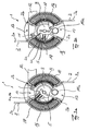
- FIGS. 3a and 3b show the switching system 1 in the closed or opened state.
- the contact state flows via the connecting rails 2 and 3, the contact points 4a, 4b and the contact bridge 5, an electric current.
- the fixed contacts 4a are in direct mechanical and electrical contact with the respective moving contacts 4b ( Fig. 3a ).
- the bearing part 8 is rotated about the axis of rotation 6 by means of the coupling rods 12 and also the contact bridge 5, and consequently the moving contacts 4b are mechanically separated from the associated stationary contacts 4a. Between them, due to the magnitude of the electric current and the magnitude of the voltage, respectively, a first arc and a second arc formed. The current continues to flow through the switching system 1 due to the arcs.
- the magnetic field 28 generated by the magnetic element 15 causes a Lorentz force on the arcs, so that they are deflected perpendicular to the propagation direction and perpendicular to the magnetic field 28.
- the arcs are comparatively short time away from the contact points 4a, 4b, which protects their contacts from excessive stress and damage. Due to the rectilinearity of the arcs they are moved by means of the magnetic field 28 in the same direction and to the same quenching chamber 16 out. Due to both the continued rotation of the contact bridge 5 about the axis of rotation 6 and the increasing distance of the respective arc to the axis of rotation 6, the length of the first arc is increased.
- the respective arc is driven by means of the magnetic field 28 in the corresponding laminated core of the quenching chamber 16. There, the arc is split into a number of partial arcs between the quenching plates 18. The electrical voltage needed to maintain the current flow through the switching system 1 is thus increased once more.
- the second arc is moved from the side facing away from the first arc of the contact bridge 5 to that side of the switching system 1, on which the quenching chamber 16, within which the first arc is arranged.
- the second arc is accelerated by means of the magnetic field 28 radially outward to this quenching chamber 16. Due to the rotation, the length of the second arc can be shortened or remain constant. The movement in the radial direction causes an increase in its length.
- the second arc will not be further shortened due to the rotation. Rather, its length is increased with increasing distance from the axis of rotation 6.
- the second arc is also split into a number of partial arcs between the quenching plates 18. This and the movement of the partial arcs radially outward by means of the magnetic field 28 and thus an increase in the length of each partial arc lead to the extinction of the individual partial arcs. The flow of current through the switching system 1 is thus interrupted and components of the circuit are protected from overloading.
Landscapes
- Physics & Mathematics (AREA)
- Electromagnetism (AREA)
- Arc-Extinguishing Devices That Are Switches (AREA)
- Breakers (AREA)
- Chutes (AREA)
Description
Die Erfindung betrifft ein Schaltsystem mit einer beweglichen Kontaktbrücke zwischen zwei Kontaktstellen gemäß dem Oberbegriff des Anspruchs 1. Ein derartiges Schaltsystem ist beispielsweise aus der
Aus der
Aus der
Der Erfindung liegt die Aufgabe zugrunde, ein verbessertes Schaltsystem mit einer zwischen zwei Kontaktstellen beweglicher Kontaktbrücke anzugeben. Das Schaltsystem soll, vorzugsweise in Verbindung mit einem Schalter in Form eines Relais oder Schützes, für hohe Gleichspannungen von z. B. mindestens 450V und zum Tragen und Trennen eines Dauerstroms von z. B. mindestens 250A geeignet sein.The invention has for its object to provide an improved switching system with a movable between two contact points contact bridge. The switching system should, preferably in conjunction with a switch in the form of a relay or contactor, for high DC voltages of z. B. at least 450V and for carrying and separating a continuous current of z. B. at least 250A be suitable.
Diese Aufgabe wird erfindungsgemäß gelöst durch die Merkmale des Anspruchs 1. Vorteilhafte Weiterbildungen und Ausgestaltungen sind Gegenstand der Unteransprüche.This object is achieved by the features of claim 1. Advantageous developments and refinements are the subject of the dependent claims.
Das Schaltsystem weist zwei Kontaktstellen und eine dazwischen angeordnete, bewegliche Kontaktbrücke auf. Die Kontaktstellen sind somit elektrisch in Reihe geschaltet und werden von jeweils einem Festkontakt und einem Bewegkontakt gebildet, die zur Stromführung dienen, wobei der jeweilige Bewegkontakt mit der Kontaktbrücke fest verbunden ist und mit dieser bewegt wird. Vorzugsweise sind die Festkontakte an etwa U-förmig gebogenen Anschlusschienen angeordnet.The switching system has two contact points and a movable contact bridge arranged therebetween. The contact points are thus electrically connected in series and are each formed by a fixed contact and a moving contact, which serve to conduct current, wherein the respective moving contact with the contact bridge is firmly connected and is moved with this. Preferably, the fixed contacts are arranged on approximately U-shaped bent connection rails.
Die Kontaktbrücke ist um eine Rotationsachse drehbar, wobei mittels einer Drehung der Kontaktbrücke um die Rotationsachse das Schaltsystem in entweder einen leitenden oder einen nichtleitenden Zustand versetzt wird. Mit anderen Worten werden die Kontaktstellen in Folge einer Drehbewegung der nachfolgend auch als Drehbrücke bezeichneten Kontaktbrücke geöffnet oder geschlossen. Die Rotationsachse ist vorzugsweise mittig zur Kontaktbrücke angeordnet.The contact bridge is rotatable about an axis of rotation, wherein by means of a rotation of the contact bridge about the axis of rotation, the switching system is placed in either a conductive or a non-conductive state. In other words, the contact points are opened or closed as a result of a rotational movement of the contact bridge, also referred to below as a rotating bridge. The axis of rotation is preferably arranged centrally to the contact bridge.
Beim Öffnen der Kontakte, also bei einem Trennen des Bewegkontakts vom jeweiligen Festkontakt und einer dadurch bedingten Unterbrechung des Stromflusses über das Schaltsystem, kann an den Kontaktstellen ein Lichtbogen entstehen, über den bzw. das dadurch entstehende Plasma ein elektrischer Strom fließt. Aufgrund der Ausgestaltung des Schaltsystems mit einer Drehbrücke ist im Gegensatz zu einer linear bewegten Kontaktbrücke die Stromrichtung im Plasma der beiden entstehenden Teilichtbögen gleich gerichtet.When opening the contacts, so when disconnecting the moving contact from the respective fixed contact and a consequent interruption of the flow of current through the switching system, an arc may arise at the contact points, via which or the resulting plasma, an electric current flows. Due to the design of the switching system with a rotary bridge, the current direction in the plasma of the two resulting partial arcs is the same direction, in contrast to a linearly moving contact bridge.
Vorzugsweise besteht die Kontaktbrücke aus Kupfer oder einem anderen, elektrischen Strom gut leitenden Material. Die Kontakte der Kontaktstellen und die Anschlusschienen der Festkontakte bestehen geeigneterweise aus dem gleichen Material wie die Kontaktbrücke, vorzugsweise aus Kupfer.Preferably, the contact bridge made of copper or other, electrical current highly conductive material. The contacts of the contact points and the connection bars of the fixed contacts suitably consist of the same material as the contact bridge, preferably of copper.
Zur Vermeidung vor Beschädigungen und zum Erreichen einer sicheren Unterbrechung des Stromflusses, wird der Lichtbogen mittels des Magnetfelds eines magnetischen Elements in eine Löschkammer getrieben. Das Magnetfeld, das mittels des magnetischen Elements erzeugt wird, ist parallel zu der Rotationsachse der Kontaktbrücke. Auf diese Weise wird der beim Öffnen der Kontaktstellen entstehende Lichtbogen in radialer Richtung getrieben. Etwaige Komponenten des Schutzschalters, die sich entlang der Rotationsachse an die Kontaktstellen anschließen, werden geschont und nicht von dem Lichtbogen beschädigt. Insbesondere werden das Lagerteil und/oder die Eisenbleche des magnetischen Elements nicht von dem Lichtbogen erfasst.To prevent damage and to achieve a safe interruption of the current flow, the arc is transformed by means of the magnetic field of a magnetic Elements driven into a quenching chamber. The magnetic field generated by the magnetic element is parallel to the axis of rotation of the contact bridge. In this way, the resulting arc when opening the contact points arc is driven in the radial direction. Any components of the circuit breaker that connect to the contact points along the rotation axis are protected and are not damaged by the arc. In particular, the bearing part and / or the iron sheets of the magnetic element are not detected by the arc.
Zweckmäßigerweise ist hierbei das Magnetfeld zumindest teilweise senkrecht zu der Ausbreitungsrichtung des jeweiligen Lichtbogens, mittels dessen eine Lorentzkraft auf den jeweiligen Lichtbogen ausgeübt wird. Beispielsweise ist das Magnetfeld innerhalb des Schalsystems im Wesentlichen konstant. Innerhalb der Löschkammer wird der Lichtbogen zum erlöschen gebracht. Hierfür wird geeigneterweise die elektrische Spannung, die zum Aufrechterhalten des Lichtbogens benötigt wird, auf einen Wert erhöht, der oberhalb der Spannung ist, die an dem Schaltsystem anliegt.Appropriately, in this case the magnetic field is at least partially perpendicular to the propagation direction of the respective arc, by means of which a Lorentz force is exerted on the respective arc. For example, the magnetic field within the scarf system is substantially constant. Inside the quenching chamber, the arc is extinguished. For this purpose, the electrical voltage required to maintain the arc is suitably increased to a value which is above the voltage applied to the switching system.
Das Schaltsystem ist insbesondere mittels Gleichstrom betrieben, wobei über dessen Drehbrücke ein elektrischer Strom zwischen 2A und 500A fließt. Geeigneterweise beträgt der elektrische Strom 250A, mittels dessen das Schaltsystem dauerhaft betrieben ist. Zweckmäßigerweise beträgt die elektrische Spannung, die an dem Schaltsystem anliegt, zwischen 30V und 1000V, beispielsweise zwischen 450V und 800V.The switching system is operated in particular by means of direct current, wherein an electrical current flows between the 2A and 500A via its rotary bridge. Suitably, the electrical current is 250A, by means of which the switching system is permanently operated. Conveniently, the voltage applied to the switching system is between 30V and 1000V, for example between 450V and 800V.
In einer bevorzugten Ausführungsform ist die Kontaktbrücke radial beweglich und/oder drehbeweglich an einem Lagerteil angebunden. Die Anbindung erfolgt geeigneterweise indirekt über einen Drehbrückenträger, an dem die Kontaktbrücke gehalten ist. Das Lagerteil ist hierbei um die Rotationsachse drehbar, während der Drehbrückenträger in mindestens einer, vorzugsweise in zwei radialen, langlochartigen Führungskontoren des Lagerteils geführt ist. Besonders bevorzugt sind zwei Lagerteile und zwei Drehbrückenträger vorgesehen, zwischen denen die Kontaktbrücke einliegt bzw. gehalten ist. Eine Drehung des bzw. jedes Lagerteils um die Rotationsachse bewirkt einen Übergang des Schaltsystems vom geschlossenen in den geöffneten und somit vom leitenden in den nichtleitenden Zustand. Daher wird die Unterbrechung des Stromkreises durch eine Drehung des Lagerteils um die Rotationsachse und somit eine Trennung des oder der Festkontakte von dem bzw. den Bewegkontakten gewährleistet. Der oder jeder Drehbrückenträger ist hierbei drehbeweglich an dem Lagerteil angebunden und weist zweckmäßigerweise ein radiales Lagerspiel relativ zu dem jeweiligen Lagerteil auf.In a preferred embodiment, the contact bridge is radially movable and / or rotatably connected to a bearing part. The connection is suitably indirectly via a rotary bridge support, on which the contact bridge is held. The bearing part is in this case rotatable about the axis of rotation, while the rotating bridge carrier is guided in at least one, preferably in two radial, slot-like guide contours of the bearing part. Particularly preferably, two bearing parts and two rotary bridge support are provided between which the contact bridge rests or is held. A rotation of the or each bearing part about the axis of rotation causes a transition of the switching system from the closed to the open and thus from the conducting to the non-conducting state. Therefore, the interruption of the circuit is ensured by a rotation of the bearing part about the axis of rotation and thus a separation of the one or more fixed contacts of the or the moving contacts. The or each rotary bridge carrier is in this case connected rotatably to the bearing part and expediently has a radial bearing clearance relative to the respective bearing part.
Die Position des Drehbrückenträgers und somit insbesondere die Position der Kontaktbrücke sind somit relativ zu dem Lagerteil und zu der Rotationsachse veränderlich. Der Drehbrückenträger ist daher in Bezug auf das Lagerteil vorzugsweise schwimmend gelagert, kann also in Bezug zu dem Lagerteil transversal oder tangential verbracht werden. Die Beweglichkeit ist hierbei vergleichsweise gering. Insbesondere ist die Drehbeweglichkeit des Drehbrückenträgers zu dem Lagerteil kleiner als die Drehbeweglichkeit des Lagerteils in Bezug auf die Festkontakte. Auf diese Weise ist es möglich, vergleichsweise große Fertigungstoleranzen bei der Herstellung des Schutzschalters zu beherrschen, wobei dennoch eine sichere Funktionsweise gewährleistet ist. Ferner ist die Einsatzdauer des Schutzschalters erhöht, da Veränderungen der Kontakte aufgrund von Abbrand oder Verschmutzung mittels der schwimmenden Aufhängung ausgeglichen werden können.The position of the rotary bridge carrier and thus in particular the position of the contact bridge are thus variable relative to the bearing part and to the axis of rotation. The rotary bridge carrier is therefore preferably floating with respect to the bearing part, so it can be transversely or tangentially spent in relation to the bearing part. The mobility is comparatively low. In particular, the rotational mobility of the rotary bridge carrier to the bearing part is smaller than the rotational mobility of the bearing part with respect to the fixed contacts. In this way, it is possible to control comparatively large manufacturing tolerances in the manufacture of the circuit breaker, while still ensuring safe operation. Furthermore, the service life of the circuit breaker is increased because changes in the contacts due to burn or contamination can be compensated by means of the floating suspension.
Bevorzugt wird eine dauerhafte Funktion der Kontaktbrücke, die zweckmäßigerweise von den beiden elektrisch isolierenden und thermisch besonders stabilen Drehbrückenträgern aufgenommen ist, in Folge der nur indirekt auf einer starren Achse angeordneten Kontaktbrücke erreicht, indem diese vorzugsweise auf beiden Seiten mit jeweils einem drehbaren Lagerteil gekoppelt ist. Die Kopplung erfolgt dabei geeigneterweise über, vorzugsweise beidseitig, jeweils eine Feder. Die Feder ist bei geschlossenen Kontaktstellen des Schaltsystems - also im eingeschalteten Zustand - gespannt (vorgespannt) und erzeugt somit einen besonders effektiven Kontaktdruck der Bewegkontakte auf die Festkontakte. In Folge dieser federbelasteten schwimmenden Lagerung der Kontaktbrücke ist gewährleistet, dass auch bei unterschiedlichem Kontaktabbrand an den Kontaktstellen der Kontaktdruck stets gleichmäßig auf beide Kontaktstellen und die dortigen Kontakte verteilt wird. Eine zusätzlich realisierte Reserve der Federkraft der oder jeder Feder ist für eine Abbrandkompensation besonders zweckmäßig. Zudem tragen die nachfolgend auch als Kontaktdruckfedern bezeichneten Federn zur Beschleunigung der Kontaktbrücke bei.Preferably, a permanent function of the contact bridge, which is suitably accommodated by the two electrically insulating and thermally particularly stable rotating bridge carriers, as a result of arranged only indirectly on a rigid axis contact bridge achieved by these is preferably coupled on both sides, each with a rotatable bearing part. The coupling is suitably via, preferably on both sides, one spring each. The spring is in closed contact points of the switching system - ie in the on state - tensioned (biased) and thus produces a particularly effective contact pressure of the moving contacts on the fixed contacts. As a result of this spring-loaded floating mounting the contact bridge ensures that even with different contact erosion at the contact points of the contact pressure is always evenly distributed to both contact points and the contacts there. An additional realized reserve of the spring force of the or each spring is particularly useful for Abbrandkompensation. In addition, the springs, also referred to below as contact pressure springs, contribute to the acceleration of the contact bridge.
Die radiale Beweglichkeit der Kontaktbrücke gegenüber dem Lagerteil ist bevorzugt dadurch realisiert, dass der jeweilige Drehbrückenträger in mindestens einer, vorzugsweise in zwei radialen Führungskontoren des Lagerteils geführt ist. Am Drehbrückenträger vorgesehene, vorzugsweise daran angeformte, Lagerelementen nehmen die Federenden der jeweiligen Kontaktdruckfeder auf. Diese Lagerelemente liegen bzw. greifen in Aussparungen des Lagerteils ein. Die Aussparungen sind kreisbogenförmig und übernehmen praktisch keine Führungsfunktion für den Drehbrückenträger, um eine Überbestimmtheit und damit ein Klemmen des beweglichen Drehbrückenträgers gegenüber dem Lagerteil zu vermeiden.The radial mobility of the contact bridge with respect to the bearing part is preferably realized in that the respective rotary bridge carrier in at least one, is preferably guided in two radial guide contours of the bearing part. Provided on the rotary bridge support, preferably formed thereon, bearing elements take on the spring ends of the respective contact pressure spring. These bearing elements are or engage in recesses of the bearing part. The recesses are circular arc-shaped and take virtually no leadership function for the rotating bridge carrier in order to avoid overdetermination and thus jamming of the movable rotating bridge carrier relative to the bearing part.
In geeigneter Ausgestaltung ist die jeweilige Feder zwischen zwei Stützelementen des Lagerteils positioniert. Die zweckmäßigerweise zylindrischen Stützelemente sind im Bereich der Drehachse des Lagerteils und somit diesbezüglich zentral hintereinander zwischen den Führungskonturen und ggf. zwischen den Aussparungen des Lagerteils angeordnet. Die jeweilige Feder, die zwischen den beiden vorzugsweise an das jeweilige Lagerteil angeformten Stützelementen einliegt, ist in diesem Bereich etwa z-förmig gebogen.In a suitable embodiment, the respective spring is positioned between two support elements of the bearing part. The expediently cylindrical support elements are arranged in the region of the axis of rotation of the bearing part and thus in this respect centrally one behind the other between the guide contours and possibly between the recesses of the bearing part. The respective spring, which rests between the two preferably integrally formed on the respective bearing part support elements, is bent in this area approximately z-shaped.
In einer geeigneten Ausführungsform weist die Löschkammer eine Anzahl von radial verlaufenden Löschblechen auf. Mit anderen Worten sind die Löschbleche fächerartig angeordnet, wobei der Abstand zwischen zwei benachbarten Löschblechen mit zunehmender Entfernung zu der Rotationsachse vergrößert ist. Geeigneterweise sind zwei Gruppen dieser fächerartig angeordneten Löschbleche gebildet, wobei zwischen diesen Löschblechgruppen auf gegenüberliegenden Seiten löschblechfrei Bereiche gebildet sind. In diesen Bereichen ist vorzugsweise jeweils eine U-förmige Anschlussschiene angeordnet und zweckmäßigerweise radial verlaufend eingepasst. Die jeweilige Anschlussschiene trägt jeweils einen der Festkontakte, die zusammen mit den von der Kontaktbrücke getragenen Bewegkontakten die beiden Kontaktstellen bilden.In a suitable embodiment, the quenching chamber has a number of radially extending quenching plates. In other words, the quenching plates are arranged fan-shaped, wherein the distance between two adjacent quenching plates is increased with increasing distance to the axis of rotation. Suitably, two groups of these fan-like arranged quenching plates are formed, wherein between these splitter plate groups are formed on opposite sides free of sheet metal areas. In these areas, a U-shaped connecting rail is preferably arranged in each case and expediently fitted in a radially extending manner. The respective connecting rail carries one of the fixed contacts, which form the two contact points together with the moving contacts carried by the contact bridge.
Die Spannung, die zur Aufrechterhaltung eines zwischen den Löschblechen gebildeten Lichtbogens benötigt ist, steigt mit zunehmender Entfernung des Lichtbogens von der Rotationsachse an. Der bei einer Betriebsspannung entstehende und in die Löschkammer getriebene Lichtbogen bricht daher zusammen, wenn der Lichtbogen weit genug in die Löschkammer hinein und von der Rotationsachse weg bewegt ist. Das Bewegen erfolgt zweckmäßigerweise ebenfalls mittels des magnetischen Elements. Auf diese Weise wird der Lichtbogen zum Erlöschen gebracht.The voltage needed to maintain an arc formed between the quenching plates increases with increasing distance of the arc from the axis of rotation. The resulting at an operating voltage and driven into the quenching arc therefore breaks down when the arc far enough into the quenching chamber and from the axis of rotation is moved away. The movement is expediently also carried out by means of the magnetic element. In this way the arc is extinguished.
Besonderes bevorzugt ist das Schaltsystem im Wesentlichen punkt- und/oder rotationssymmetrische zur Rotationsachse aufgebaut. Insbesondere umfasst der Schutzschalter zwei Löschkammern. Aufgrund dieses Aufbaus ist das Schaltsystem in beide Stromrichtungen sicher betreibbar, wobei jeweils eine der Löschkammern den Lichtbogen löscht, der während des Betriebs in eine der Stromrichtungen beim Öffnen der Kontaktstellen entsteht. Insbesondere muss während des Einbaus des Schaltsystems bei Gleichstrombetrieb eine Orientierung des Schutzschalters nicht beachtet werden.Particularly preferably, the switching system is constructed substantially point- and / or rotationally symmetrical to the axis of rotation. In particular, the circuit breaker comprises two extinguishing chambers. Due to this construction, the switching system can be safely operated in both current directions, with one of the extinguishing chambers extinguishing the arc which arises during operation in one of the current directions when opening the contact points. In particular, during installation of the switching system in DC operation, an orientation of the circuit breaker must be disregarded.
Zweckmäßigerweise weist das magnetische Element zwei Eisenbleche auf, die die Kontaktbrücke im Wesentlichen überdecken und derart angeordnet sind, dass die Rotationsachse senkrecht zu diesen ist. Hierbei befindet sich die Kontaktbrücke insbesondere zwischen den beiden Blechen. Die Kontaktbrücke ist somit drehbar angeordnet, ohne dass eines der Bleche diese Beweglichkeit einschränkt.Expediently, the magnetic element has two iron sheets which essentially cover the contact bridge and are arranged such that the axis of rotation is perpendicular to the latter. Here, the contact bridge is located in particular between the two sheets. The contact bridge is thus rotatably arranged without one of the sheets restricting this mobility.
Mit zumindest einem der Bleche und insbesondere beiden Blechen ist mindestens ein Permanentmagnet in magnetischem Kontakt. Dabei ist zweckmäßigerweise der jeweilige Permanentmagnet entweder direkt in mechanischem Kontakt mit den Blechen oder indirekt über ein weiteres ferromagnetisches Element, wie zum Beispiel einen Eisenstab. Der Permanentmagnet magnetisiert die Bleche derart, dass zwischen diesen ein im Wesentlichen konstantes Magnetfeld gebildet ist. Dieses Magnetfeld durchsetzt die Kontaktbrücke und treibt die bei einer Öffnung der Kontaktstellen entstehenden Lichtbögen in die Löschkammer. Insbesondere ist das magnetische Element nicht rotationssymmetrisch, sondern exzentrisch zu der Rotationsachse an einer bestimmten Position angeordnet.With at least one of the sheets and in particular two sheets, at least one permanent magnet is in magnetic contact. It is expediently the respective permanent magnet either directly in mechanical contact with the sheets or indirectly via another ferromagnetic element, such as an iron rod. The permanent magnet magnetizes the sheets such that a substantially constant magnetic field is formed between them. This magnetic field passes through the contact bridge and drives the resulting arcs at an opening of the contact points in the quenching chamber. In particular, the magnetic element is not rotationally symmetrical, but arranged eccentrically to the axis of rotation at a certain position.
Die Art der Anbindung der Kontaktbrücke des Schaltsystems an dem Lagerteil kann auch unabhängig von dem magnetischen Element und der Löschkammer erfolgen. Vielmehr wird diese als eigenständige Erfindung betrachtet.The type of connection of the contact bridge of the switching system to the bearing part can also be independent of the magnetic element and the quenching chamber. Rather, it is considered as an independent invention.
Nachfolgend wird ein Ausführungsbeispiel der Erfindung anhand einer Zeichnung näher erläutert. Darin zeigen:
- Fig. 1
- in einer Explosionszeichnung ein erfindungsgemäßes Schaltsystem mit einer drehbeweglichen Kontaktbrücke (Drehbrücke) und mit zwei Löschkammern,
- Fig. 2
- die Drehbrücke in einer Explosionszeichnung,
- Fig. 3a u. 3b
- in einer Draufsicht das Schaltsystem bei geschlossenen bzw. geöffneten Kontakten,
- Fig. 4
- perspektivisch ein magnetisches Element des Schaltsystems, und
- Fig. 5
- perspektivisch das Schaltsystem gemäß
Fig. 1 in zusammengebautem Zustand.
- Fig. 1
- in an exploded view of an inventive switching system with a rotatable contact bridge (swing bridge) and with two extinguishing chambers,
- Fig. 2
- the swing bridge in an exploded view,
- Fig. 3a u. 3b
- in a plan view the switching system with closed or opened contacts,
- Fig. 4
- in perspective, a magnetic element of the switching system, and
- Fig. 5
- in perspective, the switching system according to
Fig. 1 in assembled condition.
Einander entsprechende Teile sind in allen Figuren mit den gleichen Bezugszeichen versehen.Corresponding parts are provided in all figures with the same reference numerals.
In den
Die Anschlüsse 2a, 3a sind von Schienenschenkeln von etwa U-förmig gebogenen Anschlussschienen 2, 3 gebildet, die jeweils im Bereich der Abkröpfung oder Biegung einen Festkontakt 4a aufweisen. Im Kontaktfall steht mit jedem Festkontakt 4a jeweils ein Bewegkontakt 4b in mechanischem und elektrischem Kontakt, welche zusammen jeweils eine Kontaktstelle 4a, 4b bilden. Der jeweils weitere, vergleichsweise kurze Schienenschenkel 2b, 3b der Anschlussschienen 2 bzw. 3 verläuft ebenso wie die vergleichsweise langen Anschluss- ober Schienenschenkel 2a, 3a etwa radial.The
Die Bewegkontakte 4b werden von einer Kontaktbrücke 5 aus Kupfer getragen, die um eine Rotationsachse 6 drehbar ist. Hierfür ist die Kontaktbrücke 5 beidseitig in jeweils einen Drehbrückenträger 7 eingesetzt. Jeder Drehbrückenträger 7, der aus einem elektrisch isolierenden und thermisch vergleichsweise stabilen Material gefertigt ist, ist an einem Lagerteil 8 angebunden. Somit nehmen die Drehbrückenträger 7 die Kontaktbrücke 5 und die Lagerteile 8 die Drehbrückenträger 7 zwischen sich auf.The moving
Jedes Lagerteil 8 weist im Wesentlichen mittig, dem Drehbrückenträger 7 abgewandt einen Lagerzapfen 9a auf, der in eine korrespondierende Lagerausnehmung 9b innerhalb eines nachfolgend als Gehäuseteil bezeichneten Gehäusedeckels oder einer Gehäusehalbschale 10 eingreift. Die Lagerzapfen 9a und die Lagerausnehmung 9b bilden zusammen jeweils eine Lagerstelle, mit Hilfe derer die Kontaktbrücke 5 um die Rotationsachse 6 verschwenkt werden kann. Exzentrisch zu dem jeweiligen Lager 9a, 9b ist an jedem Lagerteil 8 in dessen jeweiligen Randbereich eine Nocke 11 angebracht, die in eine Kopplungsstange 12 eingreift. Jede Kopplungsstange 12 ist innerhalb einer dem Lagerteil 8 abgewandten Führungskontur oder -nut 13 des jeweiligen Gehäuseteils 10 geführt, so dass eine transversale Bewegung der Kopplungsstange 12 in einer Drehung des Lagerteils 8 um die Rotationsachse 6 resultiert.Each bearing
Jeder Gehäusedeckel 10 weist ferner eine Aussparung 14 auf, die an die jeweilige Führungsnut 13 angrenzt. In der jeweiligen Aussparung 14 liegt ein Eisenblech 15a eines magnetischen Elements 15 (
Radial zur Rotationsachse 6 sind um die Kontaktbrücke 5 zwei halbkreisförmige Löschkammern 16 angeordnet. Zwischen den beiden Löschkammern 16 sind zwei Bereiche 17 ohne Löschbleche (löschblechfreie Bereiche), in denen die Anschlussschienen 2, 3 angeordnet sind. Jede Löschkammer 16 weist eine Mehrzahl von radial verlaufenden und sich parallel zur Rotationsachse 6 erstreckenden Löschblechen 18 auf. Die Löschbleche 18 sind somit aufgefächert und der Abstand zwischen zwei benachbarten Löschblechen 17 nimmt mit zunehmender Entfernung zu der Rotationsachse 6 zu. Die Löschbleche 18 bzw. die Löschkammern 16 und die geformten Anschlussschienen 2, 3 umgeben die Kontaktbrücke 5 in radialer Richtung vollständig, wobei die Kontaktbrücke 5 mittels des Lagerteils 8 entlang der Löschkammer 16 bewegbar ist.Radially to the axis of rotation 6 5 two
Im zusammengesetzten Zustand ist das Schaltsystem 1 im Wesentlichen zylinderförmig, wobei die Eisenbleche 15a und Teile der Gehäusedeckel 10 die jeweiligen Grundflächen bilden. Die Mantelflächen umfassen die Löschkammern 16 sowie ebenfalls Teile der Gehäusedeckel 10. Mit Ausnahme sowohl des magnetischen Elements 15 als auch der Koppelstange 12 sowie der der Koppelstange 12 zugeordneten Nocken 11 ist das Schaltsystem 1 im Wesentlichen rotationssymmetrisch zu der Rotationsachse 6 und punktsymmetrisch zu einem auf der Rotationsachse 6 liegenden Punkt aufgebaut.In the assembled state, the switching system 1 is substantially cylindrical, wherein the
In
Jedes Lagerelement 22 liegt in einer tangential verlaufenden, gebogenen oder gekrümmten Ausnehmung 24 des Lagerteils 8 ein. Mittels der Ausgestaltung der Aussparung 24 und aufgrund eines zumindest geringen Spiels der drehbrückenseitigen Führungsstifte 21 in den lagerteilseitigen Führungskonturen 23 ist der Drehbrückenträger 14 in Bezug zum Lagerteil 8 um die Rotationsachse 6 um einen Winkel von maximal 5° drehbeweglich.Each bearing
Das Lagerelement 22 ist, insbesondere mittig, geschlitzt. In den entsprechenden Schlitzen oder Kerben 25 liegen die Federenden einer Feder 26 ein, die blattfederartig ausgestaltet und als eine Dreh- und Kontaktdruckfeder wirksam ist. Die Feder 26 ist um zwei erhabene, zylinderförmige und im Bereich der Rotationsachse 8 angeordnete Stützelemente 27 des Lagerteils 8 gebogen. Die Feder 26 ist im geschlossenen Zustand der Kontaktstellen 4a, 4b vorgespannt und erzeugt somit einen gewünschten oder erforderlichen Kontaktdruck der Kontaktbrücke 5 auf die Anschlussschienen 2, 3. In Verbindung mit der schwimmenden Lagerung der Kontaktbrücke 5 gewährleistet die Feder 26 im Einschaltzustand des Schaltsystems 1, dass auch bei unterschiedlichem Kontaktabbrand der Kontakte 4a, 4b der Kontaktdruck stets gleichmäßig auf die Kontaktstellen 4a, 4b verteilt wird. Bei einer Bewegung des Drehbrückenträgers 7 relativ zu dem Lagerteil 8 wird die Feder 26 gebogen und mithin eine Federkraft erzeugt, die den Drehbrückenträger 7 in dessen ursprüngliche Position und somit die Kontaktbrücke 5 in den Schließzustand treibt.The bearing
Aufgrund der schwimmenden Lagerung des Drehbrückenträgers 7 bzw. der Kontaktbrücke 5 in Bezug auf das Lagerteil 8 ist es ermöglicht, bei der Herstellung des Schaltsystems 1 vergleichsweise hohe Fertigungstoleranzen zuzulassen. Bei einer Rotation des Lagerteils 8 um die Rotationsachse 6 aus der Kontaktstellung heraus, wird mittels der Feder 26 der Kontakt zwischen den Kontakten 4a, 4b solange aufrechterhalten, bis die Führungsstifte 21 an der Führungskontur 23 des Lagerteils 8 anliegen oder die Feder 26 entspannt ist. Mittels einer Drehung des Lagerteils 8 über diesen Zustand hinaus werde die Kontaktstellen 4a, 4b geöffnet.Due to the floating mounting of the
In
Die
Das von dem magnetischen Element 15 erzeugte Magnetfeld 28 bewirkt auf die Lichtbögen eine Lorentzkraft, so dass diese senkrecht zu deren Ausbreitungsrichtung und senkrecht zu dem Magnetfeld 28 abgelenkt werden. Somit werden die Lichtbögen vergleichsweise kurzzeitig von den Kontaktstellen 4a, 4b wegbewegt, was deren Kontakte vor einer übermäßigen Belastung und Beschädigung schütz. Aufgrund der Gleichgerichtetheit der Lichtbögen werden diese mittels des Magnetfelds 28 in die gleiche Richtung und zur gleichen Löschkammer 16 hin bewegt. Aufgrund sowohl der fortgesetzten Drehung der Kontaktbrücke 5 um die Rotationsachse 6 als auch der zunehmenden Entfernung des jeweiligen Lichtbogens zu der Rotationsachse 6 wird die Länge des ersten Lichtbogens vergrößert. Der andere Lichtbogen wird hingegen auf die Rotationsachse 6 zu bewegt, weshalb sich dessen Länge vergleichsweise wenig ändert. Mit zunehmender Länge jedes der Lichtbögen steigt die elektrische Spannung, die zum Aufrechterhalten der Lichtbögen benötigt ist. Überschreitet diese bereits die an dem Schaltsystem 1 anliegende elektrische Spannung, so erlöschen die Lichtbogen. Der Stromfluss über das Schaltsystem 1 ist somit unterbrochen.The
Der jeweilige Lichtbogen wird mittels des Magnetfelds 28 in das entsprechende Blechpaket der Löschkammer 16 getrieben. Dort wird der Lichtbogen in eine Anzahl von Teillichtbögen zwischen den einzelnen Löschblechen 18 aufgespalten. Die elektrische Spannung, die zum Aufrechterhalten des Stromflusses durch das Schaltsystem 1 benötigt ist, wird somit ein weiteres Mal erhöht. Mittels des Magnetfeldes 28 ist der zweite Lichtbogen von der dem ersten Lichtbogen abgewandten Seite der Kontaktbrücke 5 zu derjenigen Seite des Schaltsystems 1 bewegt, auf der die Löschkammer 16, innerhalb derer der erste Lichtbogen ist, angeordnet ist. Der zweite Lichtbogen wird mittels des Magnetfelds 28 radial nach außen auf diese Löschkammer 16 zu beschleunigt. Aufgrund der Drehung kann die Länge des zweiten Lichtbogens verkürzt werden oder konstant bleiben. Die Bewegung in radialer Richtung bewirkt eine Vergrößerung von dessen Länge. Diese beiden Effekte führen dazu, dass die Länge des zweiten Lichtbogens im Wesentlichen konstant bleibt, wobei bei Überschreiten der Höhe der Achse 6 der zweite Lichtbogen deutlich aufgeweitet wird.The respective arc is driven by means of the
Wenn die Kontaktbrücke 5 nicht weiter gedreht werden kann, wird der zweite Lichtbogen aufgrund der Drehung nicht weiter verkürzt. Vielmehr wird dessen Länge mit zunehmendem Abstand von der Rotationsachse 6 erhöht. In der jeweiligen Löschkammer 16 wird der zweite Lichtbogen ebenfalls in eine Anzahl von Teillichtbögen zwischen den einzelnen Löschblechen 18 aufgespalten. Dies sowie die Bewegung der Teillichtbögen radial nach außen mittels des Magnetfelds 28 und somit eine Vergrößerung der Länge eines jeden Teillichtbogens führen zum Erlöschen der einzelnen Teillichtbögen. Der Stromfluss über das Schaltsystem 1 ist somit unterbrochen und Komponenten des Stromkreises werden vor einer Überbelastung geschützt.If the
Die Erfindung ist nicht auf das vorstehend beschriebene Ausführungsbeispiel beschränkt. Vielmehr können auch andere Varianten der Erfindung von dem Fachmann hieraus abgeleitet werden, ohne den Gegenstand der Erfindung zu verlassen. Insbesondere sind ferner alle im Zusammenhang mit dem Ausführungsbeispiel beschriebene Einzelmerkmale auch auf andere Weise miteinander kombinierbar, ohne den Gegenstand der Erfindung zu verlassen.
Claims (12)
- Switching system (1), in particular for a relay or contactor, having a contact bridge (5) arranged between two contact points (4a, 4b) and being able to rotate around an axis of rotation (6), and having at least one arcing chamber (16),
characterised by
a magnetic element (15) which generates a magnetic field (28) parallel to the axis of rotation (6) of the contact bridge (5) for impelling an arc into the arcing chamber (16), said arc arising when the contact points (4a, 4b) are open. - Switching system (1) according to claim 1,
characterised in that
the contact bridge (5) is connected to a bearing part (8) in a radial and/or rotational manner relative to the bearing part (8) by means of a swivel bridge carrier (7). - Switching system (1) according to claim 2,
characterised in that
the swivel bridge carrier (7) is guided in at least one radial guide contour (23) of the bearing part (8). - Switching system (1) according to claim 2 or 3,
characterised in that
the contact bridge (5) is coupled to the bearing part (8) by means of at least one spring (26) that is pre-tensioned when the contact points (4a, 4b) are closed. - Switching system (1) according to claim 4,
characterised in that
the swivel bridge carrier (7) lies, with bearing elements (22), in tangentially running recesses (24) of the bearing part (8), wherein the bearing elements (22) receive the springs (26) on the spring end side. - Switching system (1) according to claim 4 or 5,
characterised in that
the spring (26) is positioned between two supporting elements (27) of the bearing part (8). - Switching system (1) according to claim 6,
characterised in that
the supporting elements (27) are arranged one behind the other between the guide contours (23) and/or the recesses (24) of the bearing part (8), and the spring (26) is bent between the supporting elements (27) in a roughly z-shaped manner. - Switching system (1) according to one of claims 1 to 7,
characterised in that
the arcing chamber (16) comprises a number of radially running arc splitters (18). - Switching system (1) according to one of claims 1 to 8,
characterised in that
the contact points (4a, 4b) are formed from moving contacts (4b) borne by the contact bridge (5) and, with this, interacting fixed contacts (4a), which are each arranged on a bent connecting rail (2, 3). - Switching system (1) according to claim 9,
characterised in that
two arc splitter-free regions (17) are provided between the arc splitters (18), in which regions the connecting rails (2, 3) lie. - Switching system (1) according to one of claims 1 to 10,
characterised by
a substantially point symmetric and/or rotation symmetric construction relative to the axis of rotation (6). - Switching system (1) according to one of claims 1 to 11,
characterised in that
the magnetic element (15) comprises at least one permanent magnet (15c) and two iron sheets (15a) in magnetic contact therewith, which are arranged substantially perpendicularly to the axis of rotation (6) and at least partially cover the contact bridge (5).
Applications Claiming Priority (2)
| Application Number | Priority Date | Filing Date | Title |
|---|---|---|---|
| DE102011118418.3A DE102011118418B4 (en) | 2011-11-12 | 2011-11-12 | switching system |
| PCT/EP2012/003457 WO2013068057A1 (en) | 2011-11-12 | 2012-08-14 | Switching system |
Publications (2)
| Publication Number | Publication Date |
|---|---|
| EP2777057A1 EP2777057A1 (en) | 2014-09-17 |
| EP2777057B1 true EP2777057B1 (en) | 2015-10-28 |
Family
ID=46801413
Family Applications (1)
| Application Number | Title | Priority Date | Filing Date |
|---|---|---|---|
| EP12756088.6A Active EP2777057B1 (en) | 2011-11-12 | 2012-08-14 | Switching system |
Country Status (12)
| Country | Link |
|---|---|
| US (1) | US9431197B2 (en) |
| EP (1) | EP2777057B1 (en) |
| KR (1) | KR101823462B1 (en) |
| CN (1) | CN103930962B (en) |
| BR (1) | BR112014011257A2 (en) |
| CA (1) | CA2855914C (en) |
| DE (2) | DE102011118418B4 (en) |
| ES (1) | ES2558789T3 (en) |
| IN (1) | IN2014CN03360A (en) |
| MX (1) | MX2014005655A (en) |
| RU (1) | RU2570169C1 (en) |
| WO (1) | WO2013068057A1 (en) |
Families Citing this family (21)
| Publication number | Priority date | Publication date | Assignee | Title |
|---|---|---|---|---|
| DE102015215188B3 (en) | 2015-08-10 | 2016-12-29 | Ellenberger & Poensgen Gmbh | switching system |
| DE102016123283A1 (en) * | 2016-12-01 | 2018-06-07 | Innofas Gmbh | Device for separating a vehicle electrical system from an energy source |
| CN108122719A (en) * | 2017-12-20 | 2018-06-05 | 张正宇 | A kind of helical compression types arc-extinguishing mechanism of power circuit breaker |
| CN208622653U (en) * | 2018-04-16 | 2019-03-19 | 泰科电子(深圳)有限公司 | Relay |
| GB2580174B (en) * | 2018-12-23 | 2022-10-26 | Secheron Hasler Uk Ltd | An electrical switch and an electrical switch system |
| CN109950095B (en) * | 2019-02-26 | 2020-07-31 | 哈尔滨工业大学 | Arc extinguishing structure for relay and manufacturing method thereof |
| CN109920669A (en) * | 2019-04-10 | 2019-06-21 | 北京北元电器有限公司 | A kind of arc-control device and arc-suppressing method with monoblock type arc insulating cover |
| CN111180230B (en) * | 2020-01-15 | 2025-05-23 | 上海电器科学研究所(集团)有限公司 | Arc extinguishing system of direct current contactor |
| KR102558812B1 (en) * | 2020-03-13 | 2023-07-24 | 엘에스일렉트릭(주) | Arc extinguish part and air circuit breaker include the same |
| KR102556750B1 (en) * | 2020-03-20 | 2023-07-18 | 엘에스일렉트릭(주) | Arc extinguishing assembly and circuit breaker having the same |
| EP3905292B1 (en) * | 2020-04-28 | 2024-11-06 | ABB Schweiz AG | New design of splitter plate holder for application in medium voltage gas insulated load break switches |
| EP3905291B1 (en) * | 2020-04-28 | 2023-06-28 | ABB Schweiz AG | New design of splitter plate holder for application in medium voltage gas insulated load break switches |
| EP3985700B1 (en) | 2020-10-14 | 2023-08-09 | ABB Schweiz AG | Electric switch |
| KR102754542B1 (en) * | 2021-02-26 | 2025-01-14 | 엘에스일렉트릭(주) | Arc chute and Load break switch including the same |
| KR102754543B1 (en) * | 2021-02-26 | 2025-01-14 | 엘에스일렉트릭(주) | Arc chute and Load break switch including the same |
| KR102666104B1 (en) * | 2021-05-06 | 2024-05-20 | 엘에스일렉트릭(주) | Arc extinguish part and air circuit breaker include the same |
| FR3123143A1 (en) * | 2021-05-21 | 2022-11-25 | Socomec | Electric cut-off module equipped with a magnetic blow-out device and electric cut-off device comprising such a module |
| FR3126168B1 (en) * | 2021-08-11 | 2023-10-20 | Safran Electrical & Power | BI-DIRECTIONAL DOUBLE CUT-OFF CONTACTOR |
| KR102542180B1 (en) * | 2022-03-30 | 2023-06-14 | 오성기전 주식회사 | Arc extinguish device of DC circuit breaker |
| EP4297058B1 (en) * | 2022-05-27 | 2025-12-10 | Huawei Digital Power Technologies Co., Ltd. | Power supply system and switch unit |
| US12462991B2 (en) * | 2023-08-29 | 2025-11-04 | Siemens Industry, Inc. | Erosion resistant composite metal coating for plates of an arc chute assembly for a circuit breaker |
Family Cites Families (16)
| Publication number | Priority date | Publication date | Assignee | Title |
|---|---|---|---|---|
| FR2648952B1 (en) * | 1989-06-26 | 1991-09-13 | Merlin Gerin | LIMITING CIRCUIT BREAKER HAVING AN ELECTROMAGNETIC EFFECT CONTACT DELAY RETARDER |
| RU2074438C1 (en) * | 1994-10-14 | 1997-02-27 | Всероссийский электротехнический институт им.В.И.Ленина | Electromagnetic drive for switches |
| FR2762710B1 (en) * | 1997-04-25 | 2003-05-30 | Soule Materiel Electr | ELECTRICAL SHUTDOWN DEVICE FOR LOW AND HIGH VOLTAGE |
| DE10061394B4 (en) * | 2000-12-09 | 2008-10-09 | Moeller Gmbh | Switching device with floating, double interrupting rotary contact |
| US6791440B2 (en) * | 2002-08-02 | 2004-09-14 | General Electric Company | Apparatus for electrically isolating circuit breaker rotor components |
| WO2006133726A1 (en) * | 2005-06-16 | 2006-12-21 | Secheron S.A. | Blow-out device for an electromechanical dc circuit breaker |
| DE102006035844B4 (en) * | 2006-08-01 | 2008-06-19 | Schaltbau Gmbh | Contactor for DC and AC operation |
| CN200972833Y (en) * | 2006-10-25 | 2007-11-07 | 浙江正泰电器股份有限公司 | Automatic changover switch with quick arc extinguishing |
| DE102007040164A1 (en) * | 2007-08-21 | 2009-02-26 | Siemens Ag | Low voltage switching device e.g. power switch, for three-pole switching device arrangement, has rotary contact system arranged such that contact bridge is axially lifted in case of overvoltage or short circuit |
| JP4468431B2 (en) * | 2007-11-28 | 2010-05-26 | カルソニックカンセイ株式会社 | Multi-directional operation switch device |
| DE102008009439A1 (en) * | 2008-02-14 | 2009-08-20 | Siemens Aktiengesellschaft | Electrical circuit-breaker, has contact connected with terminals by paths running parallel to fixed pieces at side turned away from movable pieces in area of fixed pieces, where current flows in area along certain direction |
| US7683287B2 (en) * | 2008-05-08 | 2010-03-23 | Cooper Technologies Company | Multiple arc chamber assemblies for a fault interrupter and load break switch |
| DE102008037967A1 (en) * | 2008-08-13 | 2010-02-18 | Siemens Aktiengesellschaft | Rotary contact system for power switching device, has spring gripping molded inner contour of recess in spring loaded condition such that arms are provided with slack point characteristic during rotational motion relative to shaft segments |
| DE102008039187B4 (en) * | 2008-08-20 | 2019-06-19 | Siemens Aktiengesellschaft | Circuit breaker, especially for low voltage |
| DE102008049442B4 (en) * | 2008-09-29 | 2015-02-19 | Siemens Aktiengesellschaft | Rotary contact system for a switching device, in particular for a power switching device, with a radially applied from the inside closing torque |
| DE102009013337B4 (en) | 2009-03-16 | 2011-01-27 | Schaltbau Gmbh | Arc-resistant contactor |
-
2011
- 2011-11-12 DE DE102011118418.3A patent/DE102011118418B4/en not_active Expired - Fee Related
-
2012
- 2012-08-14 ES ES12756088.6T patent/ES2558789T3/en active Active
- 2012-08-14 EP EP12756088.6A patent/EP2777057B1/en active Active
- 2012-08-14 CN CN201280055525.4A patent/CN103930962B/en active Active
- 2012-08-14 KR KR1020147012722A patent/KR101823462B1/en not_active Expired - Fee Related
- 2012-08-14 MX MX2014005655A patent/MX2014005655A/en active IP Right Grant
- 2012-08-14 DE DE202012013255.5U patent/DE202012013255U1/en not_active Expired - Lifetime
- 2012-08-14 RU RU2014123700/07A patent/RU2570169C1/en not_active IP Right Cessation
- 2012-08-14 CA CA2855914A patent/CA2855914C/en not_active Expired - Fee Related
- 2012-08-14 BR BR112014011257A patent/BR112014011257A2/en not_active Application Discontinuation
- 2012-08-14 WO PCT/EP2012/003457 patent/WO2013068057A1/en not_active Ceased
-
2014
- 2014-05-05 IN IN3360CHN2014 patent/IN2014CN03360A/en unknown
- 2014-05-12 US US14/274,903 patent/US9431197B2/en active Active
Also Published As
| Publication number | Publication date |
|---|---|
| EP2777057A1 (en) | 2014-09-17 |
| US9431197B2 (en) | 2016-08-30 |
| WO2013068057A1 (en) | 2013-05-16 |
| RU2570169C1 (en) | 2015-12-10 |
| CA2855914C (en) | 2019-04-23 |
| DE102011118418B4 (en) | 2015-07-16 |
| DE202012013255U1 (en) | 2015-09-14 |
| DE102011118418A1 (en) | 2013-05-16 |
| CA2855914A1 (en) | 2013-05-16 |
| MX2014005655A (en) | 2014-08-22 |
| BR112014011257A2 (en) | 2017-04-25 |
| KR20140096056A (en) | 2014-08-04 |
| CN103930962B (en) | 2016-12-21 |
| CN103930962A (en) | 2014-07-16 |
| IN2014CN03360A (en) | 2015-07-03 |
| US20140246403A1 (en) | 2014-09-04 |
| ES2558789T3 (en) | 2016-02-08 |
| KR101823462B1 (en) | 2018-01-30 |
Similar Documents
| Publication | Publication Date | Title |
|---|---|---|
| EP2777057B1 (en) | Switching system | |
| DE3884557T2 (en) | Switch-off arrangement for multi-phase circuit breakers with rotatable double contact. | |
| EP2649628B1 (en) | Switch having a quenching chamber | |
| EP2147447B1 (en) | Switching arrangement | |
| EP2463878A1 (en) | Switch with arcing chamber | |
| EP2704172B1 (en) | Rotor for an electrical switch | |
| DE2947090A1 (en) | VACUUM CIRCUIT DISCONNECTOR | |
| EP2846339B1 (en) | Rotor for an electrical switch | |
| EP2936530B1 (en) | Power circuit breaker | |
| DE112005002227T5 (en) | Electric contactors | |
| EP2747109B1 (en) | Switching device | |
| WO2013092348A1 (en) | Switching device which is suitable for dc operation | |
| DE3319010A1 (en) | GAS INSULATED SWITCH | |
| DE102015215188B3 (en) | switching system | |
| EP2786389B1 (en) | Permanent magnet assembly for an arc driver assembly and switching device | |
| EP3928337B1 (en) | Switching device | |
| EP0980085A2 (en) | Power circuit breaker with blast coil operated by the arc | |
| DE10132858B4 (en) | breaker | |
| EP0225562A1 (en) | Vacuum-switching tubes | |
| DE19957228B4 (en) | Contact arrangement for a vacuum interrupter chamber | |
| DE102016213073A1 (en) | switching system | |
| DE102011078524A1 (en) | Double-breaking protective switching device | |
| DE69305147T2 (en) | Contact device | |
| DE102024113294A1 (en) | Contact arrangement for an electrical switching device and electrical switching device | |
| DE102024101748A1 (en) | Contact arrangement for a switching element and switching element |
Legal Events
| Date | Code | Title | Description |
|---|---|---|---|
| REG | Reference to a national code |
Ref country code: DE Ref legal event code: R138 Ref document number: 502012005112 Country of ref document: DE Free format text: GERMAN DOCUMENT NUMBER IS 502012005112 Ref country code: DE Ref legal event code: R138 Ref document number: 202012013255 Country of ref document: DE Free format text: GERMAN DOCUMENT NUMBER IS 502012005112 |
|
| PUAI | Public reference made under article 153(3) epc to a published international application that has entered the european phase |
Free format text: ORIGINAL CODE: 0009012 |
|
| 17P | Request for examination filed |
Effective date: 20140305 |
|
| AK | Designated contracting states |
Kind code of ref document: A1 Designated state(s): AL AT BE BG CH CY CZ DE DK EE ES FI FR GB GR HR HU IE IS IT LI LT LU LV MC MK MT NL NO PL PT RO RS SE SI SK SM TR |
|
| RIN1 | Information on inventor provided before grant (corrected) |
Inventor name: ENGEWALD, MANUEL |
|
| DAX | Request for extension of the european patent (deleted) | ||
| GRAP | Despatch of communication of intention to grant a patent |
Free format text: ORIGINAL CODE: EPIDOSNIGR1 |
|
| INTG | Intention to grant announced |
Effective date: 20150612 |
|
| GRAS | Grant fee paid |
Free format text: ORIGINAL CODE: EPIDOSNIGR3 |
|
| GRAA | (expected) grant |
Free format text: ORIGINAL CODE: 0009210 |
|
| AK | Designated contracting states |
Kind code of ref document: B1 Designated state(s): AL AT BE BG CH CY CZ DE DK EE ES FI FR GB GR HR HU IE IS IT LI LT LU LV MC MK MT NL NO PL PT RO RS SE SI SK SM TR |
|
| REG | Reference to a national code |
Ref country code: GB Ref legal event code: FG4D Free format text: NOT ENGLISH |
|
| REG | Reference to a national code |
Ref country code: CH Ref legal event code: EP |
|
| REG | Reference to a national code |
Ref country code: AT Ref legal event code: REF Ref document number: 758341 Country of ref document: AT Kind code of ref document: T Effective date: 20151115 |
|
| REG | Reference to a national code |
Ref country code: IE Ref legal event code: FG4D Free format text: LANGUAGE OF EP DOCUMENT: GERMAN |
|
| REG | Reference to a national code |
Ref country code: DE Ref legal event code: R096 Ref document number: 502012005112 Country of ref document: DE |
|
| REG | Reference to a national code |
Ref country code: ES Ref legal event code: FG2A Ref document number: 2558789 Country of ref document: ES Kind code of ref document: T3 Effective date: 20160208 |
|
| REG | Reference to a national code |
Ref country code: SE Ref legal event code: TRGR |
|
| REG | Reference to a national code |
Ref country code: LT Ref legal event code: MG4D |
|
| REG | Reference to a national code |
Ref country code: NL Ref legal event code: MP Effective date: 20151028 |
|
| PG25 | Lapsed in a contracting state [announced via postgrant information from national office to epo] |
Ref country code: HR Free format text: LAPSE BECAUSE OF FAILURE TO SUBMIT A TRANSLATION OF THE DESCRIPTION OR TO PAY THE FEE WITHIN THE PRESCRIBED TIME-LIMIT Effective date: 20151028 Ref country code: NL Free format text: LAPSE BECAUSE OF FAILURE TO SUBMIT A TRANSLATION OF THE DESCRIPTION OR TO PAY THE FEE WITHIN THE PRESCRIBED TIME-LIMIT Effective date: 20151028 Ref country code: IS Free format text: LAPSE BECAUSE OF FAILURE TO SUBMIT A TRANSLATION OF THE DESCRIPTION OR TO PAY THE FEE WITHIN THE PRESCRIBED TIME-LIMIT Effective date: 20160228 Ref country code: LT Free format text: LAPSE BECAUSE OF FAILURE TO SUBMIT A TRANSLATION OF THE DESCRIPTION OR TO PAY THE FEE WITHIN THE PRESCRIBED TIME-LIMIT Effective date: 20151028 Ref country code: NO Free format text: LAPSE BECAUSE OF FAILURE TO SUBMIT A TRANSLATION OF THE DESCRIPTION OR TO PAY THE FEE WITHIN THE PRESCRIBED TIME-LIMIT Effective date: 20160128 |
|
| PG25 | Lapsed in a contracting state [announced via postgrant information from national office to epo] |
Ref country code: PT Free format text: LAPSE BECAUSE OF FAILURE TO SUBMIT A TRANSLATION OF THE DESCRIPTION OR TO PAY THE FEE WITHIN THE PRESCRIBED TIME-LIMIT Effective date: 20160229 Ref country code: PL Free format text: LAPSE BECAUSE OF FAILURE TO SUBMIT A TRANSLATION OF THE DESCRIPTION OR TO PAY THE FEE WITHIN THE PRESCRIBED TIME-LIMIT Effective date: 20151028 Ref country code: GR Free format text: LAPSE BECAUSE OF FAILURE TO SUBMIT A TRANSLATION OF THE DESCRIPTION OR TO PAY THE FEE WITHIN THE PRESCRIBED TIME-LIMIT Effective date: 20160129 Ref country code: RS Free format text: LAPSE BECAUSE OF FAILURE TO SUBMIT A TRANSLATION OF THE DESCRIPTION OR TO PAY THE FEE WITHIN THE PRESCRIBED TIME-LIMIT Effective date: 20151028 Ref country code: LV Free format text: LAPSE BECAUSE OF FAILURE TO SUBMIT A TRANSLATION OF THE DESCRIPTION OR TO PAY THE FEE WITHIN THE PRESCRIBED TIME-LIMIT Effective date: 20151028 Ref country code: FI Free format text: LAPSE BECAUSE OF FAILURE TO SUBMIT A TRANSLATION OF THE DESCRIPTION OR TO PAY THE FEE WITHIN THE PRESCRIBED TIME-LIMIT Effective date: 20151028 |
|
| PG25 | Lapsed in a contracting state [announced via postgrant information from national office to epo] |
Ref country code: CZ Free format text: LAPSE BECAUSE OF FAILURE TO SUBMIT A TRANSLATION OF THE DESCRIPTION OR TO PAY THE FEE WITHIN THE PRESCRIBED TIME-LIMIT Effective date: 20151028 |
|
| REG | Reference to a national code |
Ref country code: DE Ref legal event code: R097 Ref document number: 502012005112 Country of ref document: DE |
|
| REG | Reference to a national code |
Ref country code: FR Ref legal event code: PLFP Year of fee payment: 5 |
|
| PG25 | Lapsed in a contracting state [announced via postgrant information from national office to epo] |
Ref country code: RO Free format text: LAPSE BECAUSE OF FAILURE TO SUBMIT A TRANSLATION OF THE DESCRIPTION OR TO PAY THE FEE WITHIN THE PRESCRIBED TIME-LIMIT Effective date: 20151028 Ref country code: DK Free format text: LAPSE BECAUSE OF FAILURE TO SUBMIT A TRANSLATION OF THE DESCRIPTION OR TO PAY THE FEE WITHIN THE PRESCRIBED TIME-LIMIT Effective date: 20151028 Ref country code: SM Free format text: LAPSE BECAUSE OF FAILURE TO SUBMIT A TRANSLATION OF THE DESCRIPTION OR TO PAY THE FEE WITHIN THE PRESCRIBED TIME-LIMIT Effective date: 20151028 Ref country code: EE Free format text: LAPSE BECAUSE OF FAILURE TO SUBMIT A TRANSLATION OF THE DESCRIPTION OR TO PAY THE FEE WITHIN THE PRESCRIBED TIME-LIMIT Effective date: 20151028 Ref country code: SK Free format text: LAPSE BECAUSE OF FAILURE TO SUBMIT A TRANSLATION OF THE DESCRIPTION OR TO PAY THE FEE WITHIN THE PRESCRIBED TIME-LIMIT Effective date: 20151028 |
|
| PLBE | No opposition filed within time limit |
Free format text: ORIGINAL CODE: 0009261 |
|
| STAA | Information on the status of an ep patent application or granted ep patent |
Free format text: STATUS: NO OPPOSITION FILED WITHIN TIME LIMIT |
|
| 26N | No opposition filed |
Effective date: 20160729 |
|
| PG25 | Lapsed in a contracting state [announced via postgrant information from national office to epo] |
Ref country code: SI Free format text: LAPSE BECAUSE OF FAILURE TO SUBMIT A TRANSLATION OF THE DESCRIPTION OR TO PAY THE FEE WITHIN THE PRESCRIBED TIME-LIMIT Effective date: 20151028 |
|
| PG25 | Lapsed in a contracting state [announced via postgrant information from national office to epo] |
Ref country code: BE Free format text: LAPSE BECAUSE OF NON-PAYMENT OF DUE FEES Effective date: 20160831 |
|
| PG25 | Lapsed in a contracting state [announced via postgrant information from national office to epo] |
Ref country code: MC Free format text: LAPSE BECAUSE OF FAILURE TO SUBMIT A TRANSLATION OF THE DESCRIPTION OR TO PAY THE FEE WITHIN THE PRESCRIBED TIME-LIMIT Effective date: 20151028 |
|
| REG | Reference to a national code |
Ref country code: CH Ref legal event code: PL |
|
| PG25 | Lapsed in a contracting state [announced via postgrant information from national office to epo] |
Ref country code: LI Free format text: LAPSE BECAUSE OF NON-PAYMENT OF DUE FEES Effective date: 20160831 Ref country code: CH Free format text: LAPSE BECAUSE OF NON-PAYMENT OF DUE FEES Effective date: 20160831 |
|
| REG | Reference to a national code |
Ref country code: IE Ref legal event code: MM4A |
|
| PG25 | Lapsed in a contracting state [announced via postgrant information from national office to epo] |
Ref country code: IE Free format text: LAPSE BECAUSE OF NON-PAYMENT OF DUE FEES Effective date: 20160814 |
|
| REG | Reference to a national code |
Ref country code: FR Ref legal event code: PLFP Year of fee payment: 6 |
|
| PG25 | Lapsed in a contracting state [announced via postgrant information from national office to epo] |
Ref country code: LU Free format text: LAPSE BECAUSE OF NON-PAYMENT OF DUE FEES Effective date: 20160814 |
|
| PG25 | Lapsed in a contracting state [announced via postgrant information from national office to epo] |
Ref country code: HU Free format text: LAPSE BECAUSE OF FAILURE TO SUBMIT A TRANSLATION OF THE DESCRIPTION OR TO PAY THE FEE WITHIN THE PRESCRIBED TIME-LIMIT; INVALID AB INITIO Effective date: 20120814 |
|
| PG25 | Lapsed in a contracting state [announced via postgrant information from national office to epo] |
Ref country code: MK Free format text: LAPSE BECAUSE OF FAILURE TO SUBMIT A TRANSLATION OF THE DESCRIPTION OR TO PAY THE FEE WITHIN THE PRESCRIBED TIME-LIMIT Effective date: 20151028 Ref country code: CY Free format text: LAPSE BECAUSE OF FAILURE TO SUBMIT A TRANSLATION OF THE DESCRIPTION OR TO PAY THE FEE WITHIN THE PRESCRIBED TIME-LIMIT Effective date: 20151028 Ref country code: MT Free format text: LAPSE BECAUSE OF FAILURE TO SUBMIT A TRANSLATION OF THE DESCRIPTION OR TO PAY THE FEE WITHIN THE PRESCRIBED TIME-LIMIT Effective date: 20151028 |
|
| PG25 | Lapsed in a contracting state [announced via postgrant information from national office to epo] |
Ref country code: BG Free format text: LAPSE BECAUSE OF FAILURE TO SUBMIT A TRANSLATION OF THE DESCRIPTION OR TO PAY THE FEE WITHIN THE PRESCRIBED TIME-LIMIT Effective date: 20151028 |
|
| REG | Reference to a national code |
Ref country code: FR Ref legal event code: PLFP Year of fee payment: 7 |
|
| PG25 | Lapsed in a contracting state [announced via postgrant information from national office to epo] |
Ref country code: AL Free format text: LAPSE BECAUSE OF FAILURE TO SUBMIT A TRANSLATION OF THE DESCRIPTION OR TO PAY THE FEE WITHIN THE PRESCRIBED TIME-LIMIT Effective date: 20151028 |
|
| PGFP | Annual fee paid to national office [announced via postgrant information from national office to epo] |
Ref country code: SE Payment date: 20190826 Year of fee payment: 8 Ref country code: ES Payment date: 20190919 Year of fee payment: 8 Ref country code: IT Payment date: 20190821 Year of fee payment: 8 Ref country code: TR Payment date: 20190805 Year of fee payment: 8 |
|
| PGFP | Annual fee paid to national office [announced via postgrant information from national office to epo] |
Ref country code: AT Payment date: 20190820 Year of fee payment: 8 |
|
| REG | Reference to a national code |
Ref country code: SE Ref legal event code: EUG |
|
| REG | Reference to a national code |
Ref country code: AT Ref legal event code: MM01 Ref document number: 758341 Country of ref document: AT Kind code of ref document: T Effective date: 20200814 |
|
| PG25 | Lapsed in a contracting state [announced via postgrant information from national office to epo] |
Ref country code: SE Free format text: LAPSE BECAUSE OF NON-PAYMENT OF DUE FEES Effective date: 20200815 Ref country code: AT Free format text: LAPSE BECAUSE OF NON-PAYMENT OF DUE FEES Effective date: 20200814 |
|
| PG25 | Lapsed in a contracting state [announced via postgrant information from national office to epo] |
Ref country code: IT Free format text: LAPSE BECAUSE OF NON-PAYMENT OF DUE FEES Effective date: 20200814 |
|
| REG | Reference to a national code |
Ref country code: ES Ref legal event code: FD2A Effective date: 20220110 |
|
| PG25 | Lapsed in a contracting state [announced via postgrant information from national office to epo] |
Ref country code: ES Free format text: LAPSE BECAUSE OF NON-PAYMENT OF DUE FEES Effective date: 20200815 |
|
| PG25 | Lapsed in a contracting state [announced via postgrant information from national office to epo] |
Ref country code: TR Free format text: LAPSE BECAUSE OF NON-PAYMENT OF DUE FEES Effective date: 20200814 |
|
| P01 | Opt-out of the competence of the unified patent court (upc) registered |
Effective date: 20231120 |
|
| PGFP | Annual fee paid to national office [announced via postgrant information from national office to epo] |
Ref country code: DE Payment date: 20250827 Year of fee payment: 14 |
|
| PGFP | Annual fee paid to national office [announced via postgrant information from national office to epo] |
Ref country code: GB Payment date: 20250822 Year of fee payment: 14 |
|
| PGFP | Annual fee paid to national office [announced via postgrant information from national office to epo] |
Ref country code: FR Payment date: 20250821 Year of fee payment: 14 |