KR20140092958A - Light emitting device - Google Patents
Light emitting device Download PDFInfo
- Publication number
- KR20140092958A KR20140092958A KR1020130001177A KR20130001177A KR20140092958A KR 20140092958 A KR20140092958 A KR 20140092958A KR 1020130001177 A KR1020130001177 A KR 1020130001177A KR 20130001177 A KR20130001177 A KR 20130001177A KR 20140092958 A KR20140092958 A KR 20140092958A
- Authority
- KR
- South Korea
- Prior art keywords
- layer
- dispersion
- light emitting
- band gap
- energy band
- Prior art date
Links
Images


Classifications
-
- H—ELECTRICITY
- H01—ELECTRIC ELEMENTS
- H01L—SEMICONDUCTOR DEVICES NOT COVERED BY CLASS H10
- H01L33/00—Semiconductor devices with at least one potential-jump barrier or surface barrier specially adapted for light emission; Processes or apparatus specially adapted for the manufacture or treatment thereof or of parts thereof; Details thereof
- H01L33/02—Semiconductor devices with at least one potential-jump barrier or surface barrier specially adapted for light emission; Processes or apparatus specially adapted for the manufacture or treatment thereof or of parts thereof; Details thereof characterised by the semiconductor bodies
- H01L33/14—Semiconductor devices with at least one potential-jump barrier or surface barrier specially adapted for light emission; Processes or apparatus specially adapted for the manufacture or treatment thereof or of parts thereof; Details thereof characterised by the semiconductor bodies with a carrier transport control structure, e.g. highly-doped semiconductor layer or current-blocking structure
-
- H—ELECTRICITY
- H01—ELECTRIC ELEMENTS
- H01L—SEMICONDUCTOR DEVICES NOT COVERED BY CLASS H10
- H01L33/00—Semiconductor devices with at least one potential-jump barrier or surface barrier specially adapted for light emission; Processes or apparatus specially adapted for the manufacture or treatment thereof or of parts thereof; Details thereof
- H01L33/02—Semiconductor devices with at least one potential-jump barrier or surface barrier specially adapted for light emission; Processes or apparatus specially adapted for the manufacture or treatment thereof or of parts thereof; Details thereof characterised by the semiconductor bodies
- H01L33/04—Semiconductor devices with at least one potential-jump barrier or surface barrier specially adapted for light emission; Processes or apparatus specially adapted for the manufacture or treatment thereof or of parts thereof; Details thereof characterised by the semiconductor bodies with a quantum effect structure or superlattice, e.g. tunnel junction
-
- H—ELECTRICITY
- H01—ELECTRIC ELEMENTS
- H01L—SEMICONDUCTOR DEVICES NOT COVERED BY CLASS H10
- H01L33/00—Semiconductor devices with at least one potential-jump barrier or surface barrier specially adapted for light emission; Processes or apparatus specially adapted for the manufacture or treatment thereof or of parts thereof; Details thereof
- H01L33/02—Semiconductor devices with at least one potential-jump barrier or surface barrier specially adapted for light emission; Processes or apparatus specially adapted for the manufacture or treatment thereof or of parts thereof; Details thereof characterised by the semiconductor bodies
- H01L33/12—Semiconductor devices with at least one potential-jump barrier or surface barrier specially adapted for light emission; Processes or apparatus specially adapted for the manufacture or treatment thereof or of parts thereof; Details thereof characterised by the semiconductor bodies with a stress relaxation structure, e.g. buffer layer
Abstract
Description
An embodiment relates to a light emitting element.
LED (Light Emitting Diode) is a device that converts electrical signals into infrared, visible light or light using the characteristics of compound semiconductors. It is used in household appliances, remote controls, display boards, The use area of LED is becoming wider.
In general, miniaturized LEDs are made of a surface mounting device for mounting directly on a PCB (Printed Circuit Board) substrate, and an LED lamp used as a display device is also being developed as a surface mounting device type . Such a surface mount device can replace a conventional simple lighting lamp, which is used for a lighting indicator for various colors, a character indicator, an image indicator, and the like.
LED semiconductors are grown by a process such as MOCVD or molecular beam epitaxy (MBE) on a substrate such as sapphire or silicon carbide (SiC) having a hexagonal system structure.
In the active layer, the holes provided in the p-type semiconductor layer and the electrons provided in the n-type semiconductor layer recombine to generate light. It is important to improve the recombination probability of holes and electrons in the active layer because it is an important issue for improving the light efficiency. In particular, it is important that the light efficiency can be maximized at 10 to 60 A / cm < 2 > within the driving range of commercialized products. It is also necessary to improve the efficiency droop due to the increase of the drive current density of the product.
In the active layer, the holes provided in the p-type semiconductor layer and the electrons provided in the n-type semiconductor layer recombine to generate light. It is important to improve the recombination probability of holes and electrons in the active layer because it is an important issue for improving the light efficiency.
The embodiment provides a light emitting device with improved light efficiency.
A light emitting device according to an embodiment of the present invention includes a first semiconductor layer; A current injection layer disposed on the first semiconductor layer and including a plurality of injection well layers having a smaller energy band gap than the first semiconductor layer; An active layer disposed on the current injection layer; A second semiconductor layer disposed on the active layer; And a dispersion well layer disposed between the first semiconductor layer and the current injection layer and having an energy band gap smaller than the energy band gap of the first semiconductor layer and a dispersion barrier layer having an energy band gap larger than the energy band gap of the first semiconductor layer, And a current-spreading layer including a layer.
The light emitting device according to an embodiment of the present invention can maximize the recombination rate of holes and electrons by disposing a current dispersion layer between the first semiconductor layer and the current injection layer and diffusing the current to the front of the semiconductor layer.
The light emitting device according to an embodiment of the present invention may alternately stack the dispersion well layer and the dispersion barrier layer so that electrons are horizontally dispersed in the dispersion well layer so that holes and electrons are recombined in a wider area of the active layer .
In the light emitting device according to an embodiment of the present invention, a dispersion intermediate layer is disposed between the dispersion well layer and the dispersion barrier layer, thereby reducing an instantaneous variation amount of the energy band gap in the current dispersion layer, thereby relieving the stress between the layers.
The light emitting device according to an embodiment of the present invention includes a dispersion interlayer disposed at a position in contact with the current injection layer of the dispersion barrier layer to reduce an instantaneous change in the energy band gap between the dispersion barrier layer and the current injection layer, Can be mitigated.
1 is a cross-sectional view illustrating a structure of a light emitting device according to an embodiment,
2 is a view showing an energy band gap of a light emitting device according to an embodiment,
3 is a view showing energy band gaps of the light emitting device according to the embodiment,
FIG. 4 is a view showing an energy band gap of the light emitting device according to the embodiment,
5 is a view showing energy band gaps of the light emitting device according to the embodiment,
6 is a graph showing the content of aluminum and indium in the dispersion barrier layer of the light emitting device according to the embodiment,
7A is a perspective view showing a light emitting device package including the light emitting device of the embodiment,
FIG. 7B is a cross-sectional view illustrating a light emitting device package including the light emitting device of the embodiment,
8A is a perspective view illustrating a lighting device including a light emitting device module according to an embodiment,
FIG. 8B is a cross-sectional view illustrating a lighting device including a light emitting device module according to an embodiment,
9 is an exploded perspective view showing a backlight unit including a light emitting device module according to an embodiment, and
10 is an exploded perspective view showing a backlight unit including a light emitting device module according to an embodiment.
BRIEF DESCRIPTION OF THE DRAWINGS The advantages and features of the present invention, and the manner of achieving them, will be apparent from and elucidated with reference to the embodiments described hereinafter in conjunction with the accompanying drawings. The present invention may, however, be embodied in many different forms and should not be construed as limited to the embodiments set forth herein. Rather, these embodiments are provided so that this disclosure will be thorough and complete, and will fully convey the scope of the invention to those skilled in the art. To fully disclose the scope of the invention to those skilled in the art, and the invention is only defined by the scope of the claims. Like reference numerals refer to like elements throughout the specification.
The terms spatially relative, "below", "beneath", "lower", "above", "upper" May be used to readily describe a device or a relationship of components to other devices or components. Spatially relative terms should be understood to include, in addition to the orientation shown in the drawings, terms that include different orientations of the device during use or operation. For example, when inverting an element shown in the figures, an element described as "below" or "beneath" of another element may be placed "above" another element. Thus, the exemplary term "below" can include both downward and upward directions. The elements can also be oriented in different directions, so that spatially relative terms can be interpreted according to orientation.
The terminology used herein is for the purpose of illustrating embodiments and is not intended to be limiting of the present invention. In the present specification, the singular form includes plural forms unless otherwise specified in the specification. It is noted that the terms "comprises" and / or "comprising" used in the specification are intended to be inclusive in a manner similar to the components, steps, operations, and / Or additions.
Unless defined otherwise, all terms (including technical and scientific terms) used herein may be used in a sense commonly understood by one of ordinary skill in the art to which this invention belongs. Also, commonly used predefined terms are not ideally or excessively interpreted unless explicitly defined otherwise.
The thickness and size of each layer in the drawings are exaggerated, omitted, or schematically shown for convenience and clarity of explanation. Also, the size and area of each component do not entirely reflect actual size or area.
Further, the angle and direction mentioned in the description of the structure of the light emitting device in the embodiment are based on those shown in the drawings. In the description of the structure of the light emitting device in the specification, reference points and positional relationship with respect to angles are not explicitly referred to, refer to the related drawings.
Hereinafter, embodiments will be described in detail with reference to the drawings.
1 is a cross-sectional view illustrating a structure of a light emitting device according to an embodiment.
1, a light emitting device 100 according to an exemplary embodiment of the present invention includes a
A substrate (not shown) may be disposed below the
The substrate (not shown) may have optically transmissive properties. For example, the substrate (not shown) may include, but is not limited to, sapphire (Al2O3). The substrate (not shown) may have a light transmitting property when it is formed using a light transmitting material or a material having a predetermined thickness or less, but the present invention is not limited thereto. The refractive index of the substrate (not shown) is preferably smaller than the refractive index of the
The substrate (not shown) may be formed of a semiconductor material according to an embodiment, and may include, for example, silicon (Si), germanium (Ge), gallium arsenide (GaAs), zinc oxide (ZnO), silicon carbide , Silicon germanium (SiGe), gallium nitride (GaN), gallium (III) oxide (Ga 2 O 3 ).
The substrate (not shown) may be formed of a conductive material. (Au), nickel (Ni), tungsten (W), molybdenum (Mo), copper (Cu), aluminum (Al), tantalum (Ag), platinum (Pt), and chromium (Cr), or may be formed of two or more alloys, and two or more of the above materials may be laminated. When the substrate (not shown) is formed of metal, the heat generated from the light emitting device can be easily released, thereby improving the thermal stability of the light emitting device.
The substrate (not shown) may have a PSS (Patterned Substrate) structure on its upper surface in order to enhance light extraction efficiency, but the present invention is not limited thereto. The substrate (not shown) facilitates the emission of heat generated in the light emitting device 100, thereby improving the thermal stability of the light emitting device 100.
The
The
The
The
The
When the
The
The well layers 142 and 146 may have a smaller energy bandgap than the
The
The
The doping concentration of the conductive dopant in the
When the light emitting device 100 is a horizontal type light emitting diode, a first electrode (not shown) may be disposed in one region of the
When the light emitting device 100 is a horizontal type light emitting diode, a second electrode (not shown) may be disposed in one region of the
The second electrode (not shown) may be electrically connected to the
The first electrode (not shown) and the second electrode (not shown) may be formed of a conductive material such as indium (In), cobalt (Co), silicon (Si), germanium (Ge), gold (Au), palladium ), Platinum (Pt), ruthenium (Ru), rhenium (Re), magnesium (Mg), zinc (Zn), hafnium (Hf), tantalum (Ta), rhodium (Ti), Ag, Cr, Mo, Nb, Al, Ni, Cu, and WTi, Or a multi-layered structure using a metal or an alloy selected from the group consisting of a metal, a metal, and an alloy.
A
The energy bandgaps of the injection well layers 132 and 136 may be less than the energy bandgaps of the injection barrier layers 134 and 138. [ The implantation well layers 132 and 136 may have an indium (In) content higher than the indium (In) content of the implantation barrier layers 134 and 138.
The energy bandgap of the injection well layers 132 and 136 may be greater than the well layers 142 and 146 of the
The
The
The current spreading
The thickness h1 of the
The
When the aluminum content x of the
The
Dispersing the
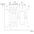
2 is a view showing an energy band gap of the light emitting device according to the embodiment.
Referring to FIG. 2, the
The
The light emitting device of one embodiment may be such that the
The energy band gap of the
The
3 is a view showing an energy band gap of the light emitting device according to the embodiment.
3, the current spreading
The dispersion
The dispersion
The injection well layer 132 may have a smaller energy band gap than the
The injection well layers 132 and 136 may have an energy band gap greater than the well layers 142 and 146 of the
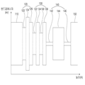
4 is a view showing energy band gaps of the light emitting device according to the embodiment.
Referring to FIG. 4, a dispersive intermediate layer 128 may be disposed between the
The dispersion intermediate layer 128 can moderate the change of the energy band gap between the
The number of the dispersion
5 is a view showing energy band gaps of the light emitting device according to the embodiment.
Referring to FIG. 5, the dispersion
And the energy bandgap decreases as the dispersion
6 is a graph showing the content of aluminum and indium in the dispersion barrier layer of the light emitting device according to the embodiment.
Referring to FIG. 6, the dispersion barrier layer may comprise aluminum indium gallium nitride (Al x In y GaN). As the content of aluminum in the dispersion barrier layer increases, the energy band gap of the dispersion barrier layer increases and the plane lattice constant decreases. As the indium content of the dispersion barrier layer increases, the energy bandgap decreases and the plane lattice constant increases.
Optimization values considering the proper aluminum and indium contents of the dispersion barrier layer are distributed in the triangle of the graph shown in FIG.
7A is a perspective view showing a light emitting
7A and 7B, a light emitting
The
The inner surface of the
The shape of the cavity formed in the
The
The phosphor (not shown) may be selected according to the wavelength of the light emitted from the
The fluorescent material (not shown) included in the
The phosphor (not shown) may be excited by the light having the first light emitted from the
When the
The phosphor (not shown) may be a known one such as YAG, TAG, sulfide, silicate, aluminate, nitride, carbide, nitridosilicate, borate, fluoride or phosphate.
The
The
The
The
The
The
The light emitting
A light guide plate, a prism sheet, a diffusion sheet, and the like, which are optical members, may be disposed on a light path of the light emitting
The light emitting
FIG. 8A is a perspective view showing an
8B is a cross-sectional view of the
8A and 8B, the
The light emitting
The light emitting
The light emitting
The
The
The light generated from the light emitting
The finishing
9 is an exploded perspective view of a liquid crystal display device including a light emitting device according to an embodiment.
9, the
The liquid
The
The thin
The thin
The
The light emitting
The light emitting
The
10 is an exploded perspective view of a liquid crystal display device including a light emitting device according to an embodiment. However, the parts shown and described in Fig. 9 are not repeatedly described in detail.
10 is a direct-view liquid
The
The light emitting
The light emitting
The
The light emitted from the light emitting
The configuration and the method of the embodiments described above are not limitedly applied, but the embodiments may be modified so that all or some of the embodiments are selectively combined so that various modifications can be made. .
While the present invention has been particularly shown and described with reference to exemplary embodiments thereof, it is to be understood that the invention is not limited to the disclosed exemplary embodiments, but, on the contrary, It should be understood that various modifications may be made by those skilled in the art without departing from the spirit and scope of the present invention.
110: first semiconductor layer 120: current dispersion layer
130: current injection layer 140: active layer
150: second semiconductor layer
300: Light emitting device package.
Claims (17)
A current injection layer disposed on the first semiconductor layer and including a plurality of injection well layers having a smaller energy band gap than the first semiconductor layer;
An active layer disposed on the current injection layer;
A second semiconductor layer disposed on the active layer; And
A dispersion well layer disposed between the first semiconductor layer and the current injection layer and having an energy band gap smaller than the energy band gap of the first semiconductor layer and an energy band gap larger than the energy band gap of the first semiconductor layer, And a current diffusion layer including a diffusion barrier layer formed on the current diffusion layer.
Wherein the current dispersion layer is formed by alternately laminating the dispersion well layer and the dispersion barrier layer.
Wherein the dispersion well layer has a higher indium content than the first semiconductor layer.
Wherein the dispersion well layer has an energy band gap smaller than an energy band gap of the first semiconductor layer.
Wherein the dispersion well layer has an energy band gap greater than an energy band gap of the injection well layer.
Wherein the injection barrier layer has a larger energy band gap than the first semiconductor layer.
Wherein the current dispersion layer further comprises a dispersion intermediate layer having an energy band gap between an energy band gap of the dispersion well layer and an energy band gap of the dispersion barrier layer.
Wherein the dispersion intermediate layer is disposed between the dispersion well layer and the dispersion barrier layer.
Wherein the dispersion intermediate layer is disposed between the dispersion barrier layer and the current injection layer.
And the energy bandgap decreases as the dispersion intermediate layer approaches the current injection layer.
Wherein the dispersion barrier layer comprises aluminum indium gallium nitride (Al x In y GaN).
Wherein the dispersion barrier layer has an aluminum content x of 0.05 to 0.25.
Wherein the dispersion barrier layer has an indium content y of 0.02 to 0.1.
Light emitting device of the distribution well layer comprises an indium gallium nitride (In z GaN).
And the indium content z of the dispersion well layer is 0.01 to 0.06.
Wherein the dispersion well layer has a thickness of 1.5 nm to 50 nm.
Wherein the dispersion well layer and the dispersion barrier layer are alternately stacked.
Priority Applications (1)
| Application Number | Priority Date | Filing Date | Title |
|---|---|---|---|
| KR1020130001177A KR102007273B1 (en) | 2013-01-04 | 2013-01-04 | Light emitting device |
Applications Claiming Priority (1)
| Application Number | Priority Date | Filing Date | Title |
|---|---|---|---|
| KR1020130001177A KR102007273B1 (en) | 2013-01-04 | 2013-01-04 | Light emitting device |
Publications (2)
| Publication Number | Publication Date |
|---|---|
| KR20140092958A true KR20140092958A (en) | 2014-07-25 |
| KR102007273B1 KR102007273B1 (en) | 2019-08-05 |
Family
ID=51739340
Family Applications (1)
| Application Number | Title | Priority Date | Filing Date |
|---|---|---|---|
| KR1020130001177A KR102007273B1 (en) | 2013-01-04 | 2013-01-04 | Light emitting device |
Country Status (1)
| Country | Link |
|---|---|
| KR (1) | KR102007273B1 (en) |
Cited By (3)
| Publication number | Priority date | Publication date | Assignee | Title |
|---|---|---|---|---|
| KR20160019799A (en) * | 2014-08-12 | 2016-02-22 | 엘지이노텍 주식회사 | Light emitting device |
| KR20160149496A (en) * | 2015-06-18 | 2016-12-28 | 엘지이노텍 주식회사 | Light emitting device and lighting system having the same |
| CN108352426A (en) * | 2015-11-09 | 2018-07-31 | Lg伊诺特有限公司 | Luminescence-utraviolet device and light emitting device package |
Citations (6)
| Publication number | Priority date | Publication date | Assignee | Title |
|---|---|---|---|---|
| KR100691283B1 (en) * | 2005-09-23 | 2007-03-12 | 삼성전기주식회사 | Nitride semiconductor device |
| KR100716647B1 (en) * | 2006-03-21 | 2007-05-09 | 서울옵토디바이스주식회사 | Light emitting diode with an energy barrier layer for current spreading |
| KR20080045943A (en) * | 2006-11-21 | 2008-05-26 | 삼성전기주식회사 | Nitride semiconductor light emitting device |
| KR100924453B1 (en) * | 2009-02-06 | 2009-11-03 | 갤럭시아포토닉스 주식회사 | Light Emitting Diode |
| KR20120116764A (en) * | 2011-04-13 | 2012-10-23 | 삼성전자주식회사 | Nitride semiconductor light emitting device |
| KR20120129666A (en) * | 2011-05-20 | 2012-11-28 | 엘지이노텍 주식회사 | Light emitting device |
-
2013
- 2013-01-04 KR KR1020130001177A patent/KR102007273B1/en active IP Right Grant
Patent Citations (6)
| Publication number | Priority date | Publication date | Assignee | Title |
|---|---|---|---|---|
| KR100691283B1 (en) * | 2005-09-23 | 2007-03-12 | 삼성전기주식회사 | Nitride semiconductor device |
| KR100716647B1 (en) * | 2006-03-21 | 2007-05-09 | 서울옵토디바이스주식회사 | Light emitting diode with an energy barrier layer for current spreading |
| KR20080045943A (en) * | 2006-11-21 | 2008-05-26 | 삼성전기주식회사 | Nitride semiconductor light emitting device |
| KR100924453B1 (en) * | 2009-02-06 | 2009-11-03 | 갤럭시아포토닉스 주식회사 | Light Emitting Diode |
| KR20120116764A (en) * | 2011-04-13 | 2012-10-23 | 삼성전자주식회사 | Nitride semiconductor light emitting device |
| KR20120129666A (en) * | 2011-05-20 | 2012-11-28 | 엘지이노텍 주식회사 | Light emitting device |
Cited By (7)
| Publication number | Priority date | Publication date | Assignee | Title |
|---|---|---|---|---|
| KR20160019799A (en) * | 2014-08-12 | 2016-02-22 | 엘지이노텍 주식회사 | Light emitting device |
| KR20160149496A (en) * | 2015-06-18 | 2016-12-28 | 엘지이노텍 주식회사 | Light emitting device and lighting system having the same |
| CN108352426A (en) * | 2015-11-09 | 2018-07-31 | Lg伊诺特有限公司 | Luminescence-utraviolet device and light emitting device package |
| JP2018534781A (en) * | 2015-11-09 | 2018-11-22 | エルジー イノテック カンパニー リミテッド | Ultraviolet light emitting device and light emitting device package |
| EP3376546A4 (en) * | 2015-11-09 | 2019-05-08 | LG Innotek Co., Ltd. | Ultraviolet light-emitting element and light-emitting element package |
| US10971648B2 (en) | 2015-11-09 | 2021-04-06 | Lg Innotek Co., Ltd. | Ultraviolet light-emitting element and light-emitting element package |
| CN108352426B (en) * | 2015-11-09 | 2021-10-12 | 苏州乐琻半导体有限公司 | Ultraviolet light emitting device and light emitting device package |
Also Published As
| Publication number | Publication date |
|---|---|
| KR102007273B1 (en) | 2019-08-05 |
Similar Documents
| Publication | Publication Date | Title |
|---|---|---|
| KR20120044726A (en) | Light-emitting element | |
| KR20140101130A (en) | Ltght emitting device | |
| KR102007273B1 (en) | Light emitting device | |
| KR20140096652A (en) | Light emitting device | |
| KR101843740B1 (en) | Light emitting device | |
| KR20130031932A (en) | Light emitting device | |
| KR101933443B1 (en) | Light emitting device | |
| KR20120052744A (en) | Light-emitting device | |
| KR20120088986A (en) | Light Emitting device and Light Emitting device Package | |
| KR101865405B1 (en) | Light emitting device | |
| KR20140124063A (en) | Light emitting device | |
| KR101818753B1 (en) | Light emitting device | |
| KR20140090282A (en) | Light emitting device | |
| KR102035192B1 (en) | Light emitting device | |
| KR101986720B1 (en) | Light emitting device | |
| KR20130025452A (en) | Light emitting device | |
| KR20140097603A (en) | Light emitting device | |
| KR102019745B1 (en) | Light emitting device | |
| KR101913712B1 (en) | Light emitting diode | |
| KR102053426B1 (en) | Light emitting device and light emitting device package having the same | |
| KR20120037772A (en) | Light emitting device | |
| KR20130039168A (en) | Light emitting device | |
| KR101855064B1 (en) | Light emitting device | |
| KR20130013968A (en) | Light emitting device | |
| KR101831329B1 (en) | Light emitting device |
Legal Events
| Date | Code | Title | Description |
|---|---|---|---|
| E902 | Notification of reason for refusal | ||
| E701 | Decision to grant or registration of patent right | ||
| GRNT | Written decision to grant |