KR20140089014A - Display device and manufacturing method thereof - Google Patents
Display device and manufacturing method thereof Download PDFInfo
- Publication number
- KR20140089014A KR20140089014A KR1020120158589A KR20120158589A KR20140089014A KR 20140089014 A KR20140089014 A KR 20140089014A KR 1020120158589 A KR1020120158589 A KR 1020120158589A KR 20120158589 A KR20120158589 A KR 20120158589A KR 20140089014 A KR20140089014 A KR 20140089014A
- Authority
- KR
- South Korea
- Prior art keywords
- light
- light source
- light guide
- layer
- display
- Prior art date
Links
Images


Classifications
-
- G—PHYSICS
- G02—OPTICS
- G02B—OPTICAL ELEMENTS, SYSTEMS OR APPARATUS
- G02B6/00—Light guides; Structural details of arrangements comprising light guides and other optical elements, e.g. couplings
- G02B6/0001—Light guides; Structural details of arrangements comprising light guides and other optical elements, e.g. couplings specially adapted for lighting devices or systems
- G02B6/0011—Light guides; Structural details of arrangements comprising light guides and other optical elements, e.g. couplings specially adapted for lighting devices or systems the light guides being planar or of plate-like form
- G02B6/0013—Means for improving the coupling-in of light from the light source into the light guide
- G02B6/0015—Means for improving the coupling-in of light from the light source into the light guide provided on the surface of the light guide or in the bulk of it
- G02B6/002—Means for improving the coupling-in of light from the light source into the light guide provided on the surface of the light guide or in the bulk of it by shaping at least a portion of the light guide, e.g. with collimating, focussing or diverging surfaces
- G02B6/0021—Means for improving the coupling-in of light from the light source into the light guide provided on the surface of the light guide or in the bulk of it by shaping at least a portion of the light guide, e.g. with collimating, focussing or diverging surfaces for housing at least a part of the light source, e.g. by forming holes or recesses
-
- G—PHYSICS
- G02—OPTICS
- G02F—OPTICAL DEVICES OR ARRANGEMENTS FOR THE CONTROL OF LIGHT BY MODIFICATION OF THE OPTICAL PROPERTIES OF THE MEDIA OF THE ELEMENTS INVOLVED THEREIN; NON-LINEAR OPTICS; FREQUENCY-CHANGING OF LIGHT; OPTICAL LOGIC ELEMENTS; OPTICAL ANALOGUE/DIGITAL CONVERTERS
- G02F1/00—Devices or arrangements for the control of the intensity, colour, phase, polarisation or direction of light arriving from an independent light source, e.g. switching, gating or modulating; Non-linear optics
- G02F1/01—Devices or arrangements for the control of the intensity, colour, phase, polarisation or direction of light arriving from an independent light source, e.g. switching, gating or modulating; Non-linear optics for the control of the intensity, phase, polarisation or colour
- G02F1/13—Devices or arrangements for the control of the intensity, colour, phase, polarisation or direction of light arriving from an independent light source, e.g. switching, gating or modulating; Non-linear optics for the control of the intensity, phase, polarisation or colour based on liquid crystals, e.g. single liquid crystal display cells
- G02F1/133—Constructional arrangements; Operation of liquid crystal cells; Circuit arrangements
- G02F1/1333—Constructional arrangements; Manufacturing methods
-
- G—PHYSICS
- G02—OPTICS
- G02B—OPTICAL ELEMENTS, SYSTEMS OR APPARATUS
- G02B6/00—Light guides; Structural details of arrangements comprising light guides and other optical elements, e.g. couplings
- G02B6/0001—Light guides; Structural details of arrangements comprising light guides and other optical elements, e.g. couplings specially adapted for lighting devices or systems
- G02B6/0011—Light guides; Structural details of arrangements comprising light guides and other optical elements, e.g. couplings specially adapted for lighting devices or systems the light guides being planar or of plate-like form
- G02B6/0013—Means for improving the coupling-in of light from the light source into the light guide
- G02B6/0023—Means for improving the coupling-in of light from the light source into the light guide provided by one optical element, or plurality thereof, placed between the light guide and the light source, or around the light source
-
- G—PHYSICS
- G02—OPTICS
- G02B—OPTICAL ELEMENTS, SYSTEMS OR APPARATUS
- G02B6/00—Light guides; Structural details of arrangements comprising light guides and other optical elements, e.g. couplings
- G02B6/0001—Light guides; Structural details of arrangements comprising light guides and other optical elements, e.g. couplings specially adapted for lighting devices or systems
- G02B6/0011—Light guides; Structural details of arrangements comprising light guides and other optical elements, e.g. couplings specially adapted for lighting devices or systems the light guides being planar or of plate-like form
- G02B6/0065—Manufacturing aspects; Material aspects
-
- G—PHYSICS
- G02—OPTICS
- G02F—OPTICAL DEVICES OR ARRANGEMENTS FOR THE CONTROL OF LIGHT BY MODIFICATION OF THE OPTICAL PROPERTIES OF THE MEDIA OF THE ELEMENTS INVOLVED THEREIN; NON-LINEAR OPTICS; FREQUENCY-CHANGING OF LIGHT; OPTICAL LOGIC ELEMENTS; OPTICAL ANALOGUE/DIGITAL CONVERTERS
- G02F1/00—Devices or arrangements for the control of the intensity, colour, phase, polarisation or direction of light arriving from an independent light source, e.g. switching, gating or modulating; Non-linear optics
- G02F1/01—Devices or arrangements for the control of the intensity, colour, phase, polarisation or direction of light arriving from an independent light source, e.g. switching, gating or modulating; Non-linear optics for the control of the intensity, phase, polarisation or colour
- G02F1/13—Devices or arrangements for the control of the intensity, colour, phase, polarisation or direction of light arriving from an independent light source, e.g. switching, gating or modulating; Non-linear optics for the control of the intensity, phase, polarisation or colour based on liquid crystals, e.g. single liquid crystal display cells
- G02F1/133—Constructional arrangements; Operation of liquid crystal cells; Circuit arrangements
- G02F1/1333—Constructional arrangements; Manufacturing methods
- G02F1/1335—Structural association of cells with optical devices, e.g. polarisers or reflectors
-
- G—PHYSICS
- G09—EDUCATION; CRYPTOGRAPHY; DISPLAY; ADVERTISING; SEALS
- G09F—DISPLAYING; ADVERTISING; SIGNS; LABELS OR NAME-PLATES; SEALS
- G09F9/00—Indicating arrangements for variable information in which the information is built-up on a support by selection or combination of individual elements
-
- B—PERFORMING OPERATIONS; TRANSPORTING
- B82—NANOTECHNOLOGY
- B82Y—SPECIFIC USES OR APPLICATIONS OF NANOSTRUCTURES; MEASUREMENT OR ANALYSIS OF NANOSTRUCTURES; MANUFACTURE OR TREATMENT OF NANOSTRUCTURES
- B82Y20/00—Nanooptics, e.g. quantum optics or photonic crystals
-
- B—PERFORMING OPERATIONS; TRANSPORTING
- B82—NANOTECHNOLOGY
- B82Y—SPECIFIC USES OR APPLICATIONS OF NANOSTRUCTURES; MEASUREMENT OR ANALYSIS OF NANOSTRUCTURES; MANUFACTURE OR TREATMENT OF NANOSTRUCTURES
- B82Y30/00—Nanotechnology for materials or surface science, e.g. nanocomposites
-
- G—PHYSICS
- G02—OPTICS
- G02B—OPTICAL ELEMENTS, SYSTEMS OR APPARATUS
- G02B6/00—Light guides; Structural details of arrangements comprising light guides and other optical elements, e.g. couplings
- G02B6/0001—Light guides; Structural details of arrangements comprising light guides and other optical elements, e.g. couplings specially adapted for lighting devices or systems
- G02B6/0011—Light guides; Structural details of arrangements comprising light guides and other optical elements, e.g. couplings specially adapted for lighting devices or systems the light guides being planar or of plate-like form
- G02B6/0013—Means for improving the coupling-in of light from the light source into the light guide
- G02B6/0023—Means for improving the coupling-in of light from the light source into the light guide provided by one optical element, or plurality thereof, placed between the light guide and the light source, or around the light source
- G02B6/0031—Reflecting element, sheet or layer
-
- Y—GENERAL TAGGING OF NEW TECHNOLOGICAL DEVELOPMENTS; GENERAL TAGGING OF CROSS-SECTIONAL TECHNOLOGIES SPANNING OVER SEVERAL SECTIONS OF THE IPC; TECHNICAL SUBJECTS COVERED BY FORMER USPC CROSS-REFERENCE ART COLLECTIONS [XRACs] AND DIGESTS
- Y10—TECHNICAL SUBJECTS COVERED BY FORMER USPC
- Y10T—TECHNICAL SUBJECTS COVERED BY FORMER US CLASSIFICATION
- Y10T29/00—Metal working
- Y10T29/49—Method of mechanical manufacture
- Y10T29/49002—Electrical device making
Landscapes
- Physics & Mathematics (AREA)
- General Physics & Mathematics (AREA)
- Optics & Photonics (AREA)
- Nonlinear Science (AREA)
- Engineering & Computer Science (AREA)
- Manufacturing & Machinery (AREA)
- Mathematical Physics (AREA)
- Chemical & Material Sciences (AREA)
- Crystallography & Structural Chemistry (AREA)
- Theoretical Computer Science (AREA)
- Planar Illumination Modules (AREA)
- Liquid Crystal (AREA)
Abstract
Description
본 발명은 표시 장치 및 그 제조 방법에 관한 것이다.The present invention relates to a display device and a method of manufacturing the same.
액정 표시 장치 등의 수광형 표시 장치는 자연광을 사용하거나 빛을 생성하는 별도의 광원을 필요로 한다. 이러한 표시 장치는 소비자의 요구에 의해 점점 더 가볍고, 더 얇아지고 있다.A light-receiving display device such as a liquid crystal display device requires a separate light source that uses natural light or generates light. Such displays are becoming lighter and thinner at the consumer's request.
또한, 가볍고 얇은 표시 장치를 구현하기 위하여 구동부의 일부분을 표시 패널에 집적하는 등의 방법이 제시되고 있으나, 수광형 표시 장치의 특성 상 필요한 별도의 광원, 예를 들면 백라이트 유닛 등으로 인하여 한계가 있다.In addition, although a method of integrating a part of a driving unit on a display panel to implement a light and thin display device has been proposed, there is a limitation due to a separate light source required for the characteristics of the light receiving display device, for example, a backlight unit .
가볍고 얇은 표시 장치를 제공하고자 한다.A light and thin display device.
한 실시예에 따른 표시 장치는, 영상을 표시하는 표시 부재, 빛을 생성하는 광원 부재, 그리고 상기 광원 부재와 상기 표시 부재 사이에 위치하며 상기 빛을 상기 표시 부재로 안내하는 도광 부재를 포함하며, 상기 표시 부재, 상기 광원 부재 및 상기 도광 부재는 일체로 형성되며, 상기 광원 부재는 청색 광을 생성하며, 상기 도광 부재는, 도광층, 그리고 상기 도광층의 윗면 또는 아랫면에 위치하며 상기 청색 광을 백색 광으로 변환하는 형광막을 포함한다.A display device according to an embodiment includes a display member for displaying an image, a light source member for generating light, and a light guiding member positioned between the light source member and the display member and guiding the light to the display member, Wherein the light guide member, the light source member, and the light guide member are integrally formed, the light source member generates blue light, and the light guide member is disposed on the light guide layer and the upper surface or the lower surface of the light guide layer, And a fluorescent film for converting into white light.
상기 도광층은 아랫 면에 형성되어 있으며 렌즈의 역할을 수행하는 복수의 홈을 가질 수 있다.The light guide layer may have a plurality of grooves formed on the lower surface and serving as a lens.
상기 도광 부재는 상기 도광층 위에 위치하는 확산층을 더 포함할 수 있다.The light guiding member may further include a diffusion layer positioned on the light guiding layer.
상기 형광막은 상기 홈의 표면에 도포될 수 있다.The fluorescent film can be applied to the surface of the groove.
상기 형광막은 상기 확산층의 윗면에 위치할 수 있다.The fluorescent film may be positioned on the upper surface of the diffusion layer.
상기 형광막은 양자점을 포함할 수 있다.The fluorescent film may include quantum dots.
상기 광원 부재는 상기 홈 내에 위치하는 광원 칩을 포함할 수 있다.The light source member may include a light source chip positioned in the groove.
상기 광원 부재는, 상기 광원 칩이 장착되어 있는 회로 기판, 그리고 상기 회로 기판 상부에 위치하는 반사층을 더 포함할 수 있다.The light source member may further include a circuit board on which the light source chip is mounted, and a reflective layer disposed on the circuit board.
다른 실시예에 따른 표시 장치는, 영상을 표시하는 표시 부재, 빛을 생성하며 상기 표시 부재의 가장자리에 부착되어 있는 광원 부재, 그리고 상기 표시 부재의 하부에 위치하며 상기 빛을 상기 표시 부재로 안내하는 도광 부재를 포함한다.A display device according to another embodiment includes a display member for displaying an image, a light source member for generating light and attached to an edge of the display member, and a light source member disposed below the display member and guiding the light to the display member And a light guiding member.
상기 도광 부재는, 도광층, 상기 도광층의 윗면에 위치하는 확산층, 상기 도광층과 상기 확산층 사이에 위치하는 접착층, 그리고 상기 도광층의 하부에 위치하는 반사층을 포함할 수 있다.The light guiding member may include a light guiding layer, a diffusion layer positioned on the upper surface of the light guiding layer, an adhesive layer positioned between the light guiding layer and the diffusion layer, and a reflective layer located under the light guiding layer.
상기 도광 부재는 상기 확산층과 상기 접착층 사이에 위치하는 역프리즘층을 더 포함할 수 있다.The light guiding member may further include an inverse prism layer positioned between the diffusion layer and the adhesive layer.
상기 표시 부재는 서로 결합되어 있는 제1 표시판과 제2 표시판을 포함하고, 상기 제1 표시판은 상기 제2 표시판보다 크며, 상기 광원 부재는 상기 제1 표시판에 부착될 수 있다.The display member includes a first display panel and a second display panel coupled to each other, wherein the first display panel is larger than the second display panel, and the light source member can be attached to the first display panel.
한 실시예에 따른 표시 장치의 제조 방법은, 서로 반대쪽에 위치한 제1면과 제2면을 가지는 도광층의 제1면에 복수의 홈을 형성하는 단계, 상기 홈에 형광막을 형성하는 단계, 상기 도광층의 제2면 위에 확산층을 적층하여 도광 부재를 형성하는 단계, 복수의 광원 칩을 포함하는 광원 부재를 상기 광원 칩이 상기 홈과 대응되도록 상기 도광 부재와 정렬시키는 단계, 상기 홈에 상기 광원 칩에 수용되도록 상기 도광 부재와 상기 광원 부재를 접착하는 단계, 그리고 상기 도광 부재에 표시 부재를 부착하는 단계를 포함한다.A method of manufacturing a display device according to an embodiment includes forming a plurality of grooves on a first surface of a light guide layer having a first surface and a second surface opposite to each other, Forming a light guide member by laminating a diffusion layer on a second surface of the light guide layer; aligning the light source member including a plurality of light source chips with the light guide member so that the light source chip corresponds to the groove; Bonding the light guide member and the light source member to be accommodated in the chip, and attaching the display member to the light guide member.
상기 도광층의 제1면에 복수의 홈을 형성하는 단계는, 상기 도광층의 홈과 동일한 모양과 배치를 가지는 홈을 몰드 제작용 판에 형성하는 단계, 광경화성 수지를 상기 몰드 제작용 판에 도포하는 단계, 상기 광경화성 수지를 경화시켜 몰드를 형성하는 단계, 그리고 상기 몰드를 사용하여 상기 도광층에 홈을 형성하는 단계를 포함할 수 있다.Wherein the step of forming the plurality of grooves on the first surface of the light guide layer comprises the steps of forming a groove having the same shape and arrangement as the grooves of the light guide layer on the mold making plate, Applying the photopolymerizable resin to the mold, forming a mold by curing the photocurable resin, and forming a groove in the light guide layer using the mold.
상기 몰드는 가요성 재질을 포함할 수 있으며, 상기 몰드를 사용하여 상기 도광층에 홈을 형성하는 단계는 상기 몰드를 롤의 외주면에 부착하는 단계를 포함할 수 있다.The mold may include a flexible material, and the step of forming the groove in the light guide layer using the mold may include attaching the mold to the outer circumferential surface of the roll.
본 실시예에 따른 표시 장치에서는 표시 부재, 도광 부재 및 광원 부재를 일체형으로 형성함과 동시에 청색 광을 사용하여 얇고 가벼운 표시 장치를 제공할 수 있다.In the display device according to this embodiment, the display member, the light guide member, and the light source member are integrally formed, and at the same time, a thin and light display device using blue light can be provided.
도 1은 본 발명의 한 실시예에 따른 표시 장치의 개략적인 단면도이다.
도 2 내지 도 9는 본 발명의 한 실시예에 따른 표시 장치의 제조 방법을 설명하기 위한 개략적인 단면도이다.
도 10은 본 발명의 다른 실시예에 따른 표시 장치의 개략적인 단면도이다.
도 11은 본 발명의 다른 실시예에 따른 표시 장치의 개략적인 단면도이다.1 is a schematic cross-sectional view of a display device according to an embodiment of the present invention.
2 to 9 are schematic cross-sectional views illustrating a method of manufacturing a display device according to an embodiment of the present invention.
10 is a schematic cross-sectional view of a display device according to another embodiment of the present invention.
11 is a schematic cross-sectional view of a display device according to another embodiment of the present invention.
첨부한 도면을 참고로 하여 기술 분야에서 통상의 지식을 가진 자가 용이하게 실시할 수 있도록 실시예에 대하여 상세히 설명한다. 본 발명은 여러 가지 상이한 형태로 구현될 수 있으며 여기에서 설명하는 실시예에 한정되지 않는다. 도면에서 본 발명을 명확하게 설명하기 위해서 설명과 관계 없는 부분은 생략하였으며, 명세서 전체를 통하여 동일 또는 유사한 구성요소에 대해서는 동일한 도면 부호를 붙였다.The present invention will be described in detail with reference to the accompanying drawings so that those skilled in the art can easily carry out the present invention. The present invention may be embodied in many different forms and is not limited to the embodiments described herein. In order to clearly illustrate the present invention, parts not related to the description are omitted, and the same or similar components are denoted by the same reference numerals throughout the specification.
도 1을 참고하여 본 발명의 한 실시예에 따른 표시 장치에 대하여 상세하게 설명한다.A display device according to an embodiment of the present invention will be described in detail with reference to FIG.
도 1은 본 발명의 한 실시예에 따른 표시 장치의 개략적인 단면도이다.1 is a schematic cross-sectional view of a display device according to an embodiment of the present invention.
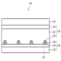
도 1을 참고하면, 본 실시예에 따른 표시 장치(100)는 차례로 부착되어 있는 표시 부재(display member)(110), 도광 부재(light guiding member)(120) 및 광원 부재(light source member)(130)를 포함한다. 표시 부재(110), 도광 부재(120) 및 광원 부재(130)는 평판 또는 필름 형태를 가지며 일체로 결합되어 있다. 표시 부재(110)는 영상을 표시하고, 광원 부재(130)는 빛을 생성하며, 도광 부재(120)는 광원 부재(130)로부터의 빛을 표시 부재(110)로 안내한다.1, the
표시 부재(110)는 액정(liquid crystal) 표시판 등 평판 형태의 수광형 영상 표시 부재일 수 있다.The
광원 부재(130)는 회로 기판(circuit board)(132), 반사층(reflective layer)(134) 및 복수의 광원 칩(light source chip)(136)을 포함한다.The
회로 기판(132)은 광원 칩(136)과 전기적으로 연결되는 복수의 회로들(도시하지 않음)을 포함하며, 가요성(flexible)일 수 있다. 회로 기판(132)은 규격화된 크기, 예를 들면 약 10.1 인치의 크기로 만들어질 수 있으며, 표시 부재(110)의 크기가 큰 경우, 복수의 회로 기판(132)이 사용될 수 있다.The
광원 칩(136)은 빛을 생성하는 광원을 포함하며, 회로 기판(132) 위에 위치한다. 광원 칩(136)은 일정 간격, 예를 들면, 약 5 mm × 5 mm 의 면적 당 하나씩 장착될 수 있다. 광원 칩(136)은 회로 기판(132)의 회로들과 연결될 수 있으며, LED(light emitting diode) 칩일 수 있다. 광원 칩(136)에서 생성되는 빛은 청색 광일 수 있다.The
반사층(134)은 광원 칩(136)을 제외한 회로 기판(132)의 부분 위에 도포될 수 있으며, 반사성 재료들로 만들어질 수 있다.The
도광 부재(120)는 도광층(light guide layer)(122), 확산층(diffusion layer)(124) 및 복수의 형광막(126)을 포함한다.The
도광층(122)은 투명 또는 반투명한 절연체로 만들어질 수 있으며, 아래 표면에는 일정한 간격으로 배열된 대체로 반구형인 복수의 홈(123)이 형성되어 있다. 이러한 홈은 광원 칩(136)에 대응하는 위치에 있으며, 광원 칩(136)에서 생성된 빛을 여러 방향으로 분산시키는 렌즈의 역할을 할 수 있다. 도광층(122)의 아랫면에서 홈(123)을 제외한 부분은 반사층(134)에 접착되어 있다.The
각 홈(123)의 표면에는 형광막(126)이 도포되어 있다. 형광막(126)은 광원 칩(136)의 청색 광을 백색 광으로 변환한다.A
확산층(124)은 도광층(122)의 윗면에 도포되어 있다.The
그러면, 도 2 내지 도 9를 참고하여 본 발명의 한 실시예에 따른 표시 장치의 제조 방법에 대하여 상세하게 설명한다.Hereinafter, a method of manufacturing a display device according to an embodiment of the present invention will be described in detail with reference to FIGS. 2 to 9. FIG.
도 2 내지 도 9는 본 발명의 한 실시예에 따른 표시 장치의 제조 방법을 설명하기 위한 개략적인 단면도이다.2 to 9 are schematic cross-sectional views illustrating a method of manufacturing a display device according to an embodiment of the present invention.
먼저, 도광 부재(120)의 제조 방법에 대하여 설명한다.First, a manufacturing method of the
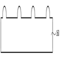
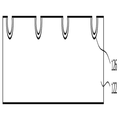
도 2를 참고하면, 레이저빔 등을 사용하여 도광층(122)의 홈(123)과 동일한 모양과 배치의 홈(153)을 몰드 제작용 판(150)에 형성한다.Referring to FIG. 2, a groove 153 having the same shape and arrangement as the
도 3 및 도 4를 참고하면, 예를 들면 자외선 경화성 수지를 몰드 제작용 판(150) 위에 도포하고 자외선을 조사하여 경화시킴으로써 홈(153)과 역상인 반구형 돌기를 포함하는 몰드(160)를 형성한다. 몰드(160)는 연성 또는 가요성 재질일 수 있으며, 이 경우 롤(도 5의 170)의 외주면에 부착될 수 있다.3 and 4, for example, an ultraviolet curing resin is coated on a mold-making
도 5를 참고하면, 외주면에 몰드(160)가 부착된 롤(170)을 사용하여 도광층(122)에 압력을 가하여 도광층(122)의 표면에 홈(123)을 형성한다.5,
도 6을 참고하면, 도광층(122)의 홈(123) 표면에 형광막(126)을 도핑하고, 도 7을 참고하면, 도광층(122)의 홈(123) 반대쪽 면에 확산층(124)을 적층함으로써 도광 부재(120)를 완성한다.7, a
도 8을 참고하면, 도광 부재(120)의 홈(123)이 광원 부재(130)의 광원 칩(136)과 마주보도록 도광 부재(120)와 광원 부재(130)를 정렬한 다음, 도광 부재(120)를 광원 부재(130)에 접착한다.8, the
도 9를 참고하면, 도광 부재(120)에 표시 부재(110)를 부착함으로써 본 실시예에 따른 표시 장치를 완성한다.Referring to Fig. 9, the display device according to the present embodiment is completed by attaching the
다음, 도 10을 참고하여 본 발명의 다른 실시예에 따른 표시 장치에 대하여 상세하게 설명한다.Next, a display device according to another embodiment of the present invention will be described in detail with reference to FIG.
도 10은 본 발명의 다른 실시예에 따른 표시 장치의 개략적인 단면도이다.10 is a schematic cross-sectional view of a display device according to another embodiment of the present invention.
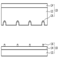
도 10을 참고하면, 본 실시예에 따른 표시 장치(200)는 도 1에 도시한 표시 장치(100)와 마찬가지로 차례로 부착되어 있는 표시 부재(210), 도광 부재(220) 및 광원 부재(230)를 포함하며, 이들은 평판 또는 필름 형태로서 일체로 결합되어 있다. 표시 부재(210)는 영상을 표시하고, 광원 부재(230)는 빛을 생성하며, 도광 부재(220)는 광원 부재(230)로부터의 빛을 표시 부재(210)로 안내한다.10, the
본 실시예에 따른 도광 부재(220)는 아래에서부터 차례로 적층된 도광층(222), 확산층(224) 및 형광막(226)을 포함한다. 도광층(222)의 아래면에는 복수의 홈이 형성되어 있다. 형광막(226)은 예를 들어 양자점(QD)을 포함할 수 있다.The
도 1에 도시한 표시 장치(100)의 도광 부재(120)는 아랫면의 홈(223) 내에 위치하는 복수의 형광막(126)을 포함하는 것에 비하여, 본 실시예에 따른 표시 장치(200)의 도광 부재(220)는 윗면에 도포되어 있는 형광막(226)을 포함한다.The
본 실시예에 따른 표시 부재(210)와 광원 부재(230)는 도 1에 도시한 표시 장치(100)와 실질적으로 동일할 수 있다. 예를 들어, 광원 부재(230)는 아래에서부터 차례로 적층된 회로 기판(232), 반사층(234) 및 복수의 광원 칩(236)을 포함할 수 있다.The
본 실시예에 따른 표시 장치(200)는 도 2 내지 도 9에 도시한 것과 유사한 방법으로 제작될 수 있는데, 도광층(222) 내부에 형광막을 형성하는 대신 확산층(224) 위에 형광막(226)을 형성한다는 점에서 도 2 내지 도 9에 도시한 것과 다르다.2 to 9, instead of forming the fluorescent film in the
다음, 도 11을 참고하여 본 발명의 다른 실시예에 따른 표시 장치에 대하여 상세하게 설명한다.Next, a display device according to another embodiment of the present invention will be described in detail with reference to FIG.
도 11은 본 발명의 다른 실시예에 따른 표시 장치의 개략적인 단면도이다.11 is a schematic cross-sectional view of a display device according to another embodiment of the present invention.
도 11을 참고하면, 본 실시예에 따른 표시 장치(300)는 표시 부재(310), 도광 부재(320) 및 광원 부재(330)를 포함한다. 표시 부재(310)는 영상을 표시하고, 광원 부재(330)는 빛을 생성하며, 도광 부재(320)는 광원 부재(330)로부터의 빛을 표시 부재(310)로 안내한다.11, the
표시 부재(310)는 서로 결합되어 있는 제1 표시판(312)과 제2 표시판(314)을 포함하며, 제1 표시판(312)과 제2 표시판(314) 사이에 위치하는 액정층을 더 포함할 수 있다. 두 표시판(312, 314)은 크기가 서로 다를 수 있는데, 예를 들면 화소 전극(도시하지 않음)과 스위칭 소자(도시하지 않음) 등이 위치한 제1 표시판(312)이 공통 전극(도시하지 않음)이 위치한 제2 표시판(314)보다 클 수 있다.The
광원 부재(330)는 광원 칩(332)과 광원 지지 부재(334)를 포함한다. 광원 지지 부재(334)는 표시 부재(310)의 제1 표시판(312)의 가장자리에 부착되어 있으며, 광원 칩(332)과 전기적으로 연결되는 복수의 회로들(도시하지 않음)을 포함할 수 있다. 광원 칩(332)은 광원 지지 부재(334)와 결합되어 있다.The
본 실시예에 따른 도광 부재(320)는 아래에서부터 차례로 적층된 도광층(322)과 그 위에 차례로 적층되어 있는 접착층(323), 역프리즘층(325) 및 확산층(324), 그리고 도광층(322) 하부에 위치하는 반사층(327)을 포함한다. The
접착층(323)은 굴절률이 낮은 물질을 포함할 수 있다.The
역프리즘층(325)은 거꾸로 배치된 복수의 미세 프리즘을 포함한다.The inverse prism layer 325 includes a plurality of inverted micro prisms.
이와 같이 본 실시예에 따른 표시 장치에서는 표시 부재, 도광 부재 및 광원 부재를 일체형으로 형성함과 동시에 청색 광을 사용하여 얇고 가벼운 표시 장치를 제공할 수 있다.As described above, in the display device according to the present embodiment, the display member, the light guide member, and the light source member are integrally formed, and a thin and light display device using blue light can be provided.
이상에서 실시예에 대하여 상세하게 설명하였지만 본 발명의 권리 범위는 이에 한정되는 것은 아니고 다음의 청구 범위에서 정의하고 있는 본 발명의 기본 개념을 이용한 당업자의 여러 변형 및 개량 형태 또한 본 발명의 권리 범위에 속하는 것이다.While the present invention has been particularly shown and described with reference to exemplary embodiments, it is to be understood that the invention is not limited to the disclosed exemplary embodiments, but, on the contrary, It belongs.
100, 200, 300: 표시 장치
110, 210, 310: 표시 부재
120, 220, 320: 도광 부재
122, 222, 322: 도광층
123, 223: 도광층의 홈
124, 224, 324: 확산층
126, 226: 형광막
130, 230, 330: 광원 부재
132, 232: 회로 기판
134, 234, 327: 반사층
136, 236, 332: 광원 칩
150: 몰드 제작용 판
153: 몰드 제작용 판의 홈
160: 몰드
170: 롤
312, 314: 표시판
323: 접착층
325: 역프리즘층
334: 광원 지지 부재100, 200, 300: display device
110, 210, 310: display member
120, 220, 320: light guiding member
122, 222, 322: light guide layer
123 and 223: grooves of the light guide layer
124, 224, 324: diffusion layer
126, 226: fluorescent film
130, 230, 330: Light source member
132, 232: circuit board
134, 234, 327: reflection layer
136, 236, 332: Light source chip
150: plate for mold making
153: groove of plate for mold making
160: mold
170: roll
312, 314:
323: Adhesive layer
325: reverse prism layer
334: Light source supporting member
Claims (15)
빛을 생성하는 광원 부재, 그리고
상기 광원 부재와 상기 표시 부재 사이에 위치하며 상기 빛을 상기 표시 부재로 안내하는 도광 부재
를 포함하고,
상기 표시 부재, 상기 광원 부재 및 상기 도광 부재는 일체로 형성되고,
상기 광원 부재는 청색 광을 생성하며,
상기 도광 부재는,
도광층, 그리고
상기 도광층의 윗면 또는 아랫면에 위치하며 상기 청색 광을 백색 광으로 변환하는 형광막
을 포함하는
표시 장치.A display member for displaying an image,
A light source member for generating light, and
A light guiding member which is positioned between the light source member and the display member and guides the light to the display member;
Lt; / RTI >
Wherein the display member, the light source member, and the light guiding member are integrally formed,
The light source member generates blue light,
The light guiding member
Light guide layer, and
A phosphor layer disposed on the upper or lower surface of the light guide layer and converting the blue light into white light;
Containing
Display device.
상기 도광층은 아랫 면에 형성되어 있으며 렌즈의 역할을 수행하는 복수의 홈을 가지는 표시 장치.The method of claim 1,
Wherein the light guide layer has a plurality of grooves formed on a lower surface thereof and serving as a lens.
상기 도광 부재는 상기 도광층 위에 위치하는 확산층을 더 포함하는 표시 장치.3. The method of claim 2,
Wherein the light guiding member further comprises a diffusion layer positioned on the light guiding layer.
상기 형광막은 상기 홈의 표면에 도포되어 있는 표시 장치.4. The method of claim 3,
And the fluorescent film is applied to the surface of the groove.
상기 형광막은 상기 확산층의 윗면에 위치하는 표시 장치.4. The method of claim 3,
And the fluorescent film is located on the upper surface of the diffusion layer.
상기 형광막은 양자점을 포함하는 표시 장치.The method of claim 5,
Wherein the fluorescent film comprises quantum dots.
상기 광원 부재는 상기 홈 내에 위치하는 광원 칩을 포함하는 표시 장치.3. The method of claim 2,
Wherein the light source member includes a light source chip located in the groove.
상기 광원 부재는,
상기 광원 칩이 장착되어 있는 회로 기판, 그리고
상기 도광층 상부에 위치하는 반사층
을 더 포함하는
표시 장치.8. The method of claim 7,
Wherein the light source member comprises:
A circuit board on which the light source chip is mounted, and
The light-reflecting layer
Further comprising
Display device.
빛을 생성하며 상기 표시 부재의 가장자리에 부착되어 있는 광원 부재, 그리고
상기 표시 부재의 하부에 위치하며 상기 빛을 상기 표시 부재로 안내하는 도광 부재
를 포함하는 표시 장치.A display member for displaying an image,
A light source member which generates light and is attached to an edge of the display member, and
And a light guiding member which is positioned below the display member and guides the light to the display member
.
상기 도광 부재는,
도광층,
상기 도광층의 윗면에 위치하는 확산층,
상기 도광층과 상기 확산층 사이에 위치하는 접착층, 그리고
상기 도광층의 하부에 위치하는 반사층
을 포함하는
표시 장치.The method of claim 9,
The light guiding member
Light guide layer,
A diffusion layer positioned on the upper surface of the light guide layer,
An adhesive layer positioned between the light guide layer and the diffusion layer, and
And a reflective layer
Containing
Display device.
상기 도광 부재는 상기 확산층과 상기 접착층 사이에 위치하는 역프리즘층을 더 포함하는 표시 장치.11. The method of claim 10,
Wherein the light guiding member further comprises an inverse prism layer positioned between the diffusion layer and the adhesive layer.
상기 표시 부재는 서로 결합되어 있는 제1 표시판과 제2 표시판을 포함하고,
상기 제1 표시판은 상기 제2 표시판보다 크며,
상기 광원 부재는 상기 제1 표시판에 부착되어 있는
표시 장치.The method of claim 9,
Wherein the display member includes a first display panel and a second display panel coupled to each other,
Wherein the first display panel is larger than the second display panel,
Wherein the light source member is attached to the first display panel
Display device.
상기 홈에 형광막을 형성하는 단계,
상기 도광층의 제2면 위에 확산층을 적층하여 도광 부재를 형성하는 단계,
복수의 광원 칩을 포함하는 광원 부재를 상기 광원 칩이 상기 홈과 대응되도록 상기 도광 부재와 정렬시키는 단계,
상기 홈에 상기 광원 칩에 수용되도록 상기 도광 부재와 상기 광원 부재를 접착하는 단계, 그리고
상기 도광 부재에 표시 부재를 부착하는 단계
를 포함하는 표시 장치의 제조 방법.Forming a plurality of grooves on a first surface of a light guide layer having a first surface and a second surface opposite to each other,
Forming a fluorescent film on the groove,
Forming a light guide member by laminating a diffusion layer on a second surface of the light guide layer,
Aligning the light source member including a plurality of light source chips with the light guide member so that the light source chip corresponds to the groove,
Adhering the light guide member and the light source member to be received in the light source chip in the groove, and
Attaching a display member to the light guide member
And a step of forming the display device.
상기 도광층의 제1면에 복수의 홈을 형성하는 단계는,
상기 도광층의 홈과 동일한 모양과 배치를 가지는 홈을 몰드 제작용 판에 형성하는 단계,
광경화성 수지를 상기 몰드 제작용 판에 도포하는 단계,
상기 광경화성 수지를 경화시켜 몰드를 형성하는 단계, 그리고
상기 몰드를 사용하여 상기 도광층에 홈을 형성하는 단계
를 포함하는
표시 장치의 제조 방법.The method of claim 13,
Wherein forming the plurality of grooves on the first surface of the light guide layer comprises:
Forming a groove having the same shape and arrangement as the grooves of the light guide layer on a mold-making plate,
Applying a photocurable resin to the mold making plate,
Curing the photocurable resin to form a mold, and
Forming a groove in the light guide layer using the mold
Containing
A method of manufacturing a display device.
상기 몰드는 가요성 재질을 포함하며,
상기 몰드를 사용하여 상기 도광층에 홈을 형성하는 단계는 상기 몰드를 롤의 외주면에 부착하는 단계를 포함하는
표시 장치의 제조 방법.The method of claim 14,
Wherein the mold comprises a flexible material,
Wherein the step of forming grooves in the light guide layer using the mold includes a step of attaching the mold to the outer circumferential surface of the roll
A method of manufacturing a display device.
Priority Applications (2)
| Application Number | Priority Date | Filing Date | Title |
|---|---|---|---|
| KR1020120158589A KR20140089014A (en) | 2012-12-31 | 2012-12-31 | Display device and manufacturing method thereof |
| US13/911,556 US9297946B2 (en) | 2012-12-31 | 2013-06-06 | Display device and method of manufacturing the same |
Applications Claiming Priority (1)
| Application Number | Priority Date | Filing Date | Title |
|---|---|---|---|
| KR1020120158589A KR20140089014A (en) | 2012-12-31 | 2012-12-31 | Display device and manufacturing method thereof |
Publications (1)
| Publication Number | Publication Date |
|---|---|
| KR20140089014A true KR20140089014A (en) | 2014-07-14 |
Family
ID=51017014
Family Applications (1)
| Application Number | Title | Priority Date | Filing Date |
|---|---|---|---|
| KR1020120158589A KR20140089014A (en) | 2012-12-31 | 2012-12-31 | Display device and manufacturing method thereof |
Country Status (2)
| Country | Link |
|---|---|
| US (1) | US9297946B2 (en) |
| KR (1) | KR20140089014A (en) |
Families Citing this family (23)
| Publication number | Priority date | Publication date | Assignee | Title |
|---|---|---|---|---|
| WO2015129222A1 (en) | 2014-02-28 | 2015-09-03 | パナソニックIpマネジメント株式会社 | Light-emitting element and light-emitting device |
| WO2015128909A1 (en) | 2014-02-28 | 2015-09-03 | パナソニックIpマネジメント株式会社 | Light-emitting element and light-emitting device |
| JP2016034015A (en) * | 2014-02-28 | 2016-03-10 | パナソニックIpマネジメント株式会社 | Light emission device |
| CN105940510B (en) | 2014-02-28 | 2019-01-11 | 松下知识产权经营株式会社 | Light emitting device |
| JP6380096B2 (en) * | 2014-12-26 | 2018-08-29 | 日亜化学工業株式会社 | Light emitting device |
| US10481316B2 (en) | 2015-01-06 | 2019-11-19 | Signify Holding B.V. | Light emitting arrangement for illuminated surfaces |
| JP6569856B2 (en) | 2015-03-13 | 2019-09-04 | パナソニックIpマネジメント株式会社 | Light emitting device and endoscope |
| US10182702B2 (en) | 2015-03-13 | 2019-01-22 | Panasonic Intellectual Property Management Co., Ltd. | Light-emitting apparatus including photoluminescent layer |
| JP2016171228A (en) | 2015-03-13 | 2016-09-23 | パナソニックIpマネジメント株式会社 | Light emission element, light emission device and detection device |
| US10031276B2 (en) | 2015-03-13 | 2018-07-24 | Panasonic Intellectual Property Management Co., Ltd. | Display apparatus including photoluminescent layer |
| JP6422572B2 (en) * | 2015-04-20 | 2018-11-14 | シャープ株式会社 | Lighting device, display device, and television receiver |
| JP2017003697A (en) | 2015-06-08 | 2017-01-05 | パナソニックIpマネジメント株式会社 | Light-emitting element and light-emitting device |
| JP2017005054A (en) | 2015-06-08 | 2017-01-05 | パナソニックIpマネジメント株式会社 | Light emission device |
| JP2017040818A (en) | 2015-08-20 | 2017-02-23 | パナソニックIpマネジメント株式会社 | Light-emitting element |
| JP6748905B2 (en) | 2015-08-20 | 2020-09-02 | パナソニックIpマネジメント株式会社 | Light emitting device |
| US10359155B2 (en) | 2015-08-20 | 2019-07-23 | Panasonic Intellectual Property Management Co., Ltd. | Light-emitting apparatus |
| JP6719094B2 (en) | 2016-03-30 | 2020-07-08 | パナソニックIpマネジメント株式会社 | Light emitting element |
| CN107170772A (en) * | 2017-05-23 | 2017-09-15 | 深圳市华星光电技术有限公司 | The encapsulating structure of micro- LED array substrate |
| TWI666495B (en) * | 2018-03-06 | 2019-07-21 | 友達光電股份有限公司 | Backlight module |
| CN110231734A (en) * | 2018-03-06 | 2019-09-13 | 中强光电股份有限公司 | Light source module and its surface light source component |
| DE102018210546A1 (en) * | 2018-06-28 | 2020-01-02 | Osram Gmbh | LIGHTING DEVICE, HEADLIGHT AND METHOD |
| KR102639988B1 (en) * | 2018-12-11 | 2024-02-22 | 엘지디스플레이 주식회사 | Liquid Crystal Display device |
| US11681090B2 (en) | 2019-05-30 | 2023-06-20 | Nichia Corporation | Light emitting module and method of manufacturing same |
Family Cites Families (24)
| Publication number | Priority date | Publication date | Assignee | Title |
|---|---|---|---|---|
| KR19980060839A (en) | 1996-12-31 | 1998-10-07 | 손욱 | Color liquid crystal display device |
| KR100615834B1 (en) | 1999-08-03 | 2006-08-25 | 삼성전자주식회사 | Liquid crystal display device for improving brightness |
| JP2002042535A (en) * | 2000-07-05 | 2002-02-08 | Internatl Business Mach Corp <Ibm> | Display device and surface light source device |
| JP3906653B2 (en) | 2000-07-18 | 2007-04-18 | ソニー株式会社 | Image display device and manufacturing method thereof |
| JP4055405B2 (en) | 2001-12-03 | 2008-03-05 | ソニー株式会社 | Electronic component and manufacturing method thereof |
| US7557781B2 (en) * | 2003-01-06 | 2009-07-07 | Tpo Displays Corp. | Planar display structure with LED light source |
| EP1455398A3 (en) * | 2003-03-03 | 2011-05-25 | Toyoda Gosei Co., Ltd. | Light emitting device comprising a phosphor layer and method of making same |
| TW200523503A (en) | 2003-09-29 | 2005-07-16 | Sony Corp | Backlight, light guiding plate, method for manufacturing diffusion plate and light guiding plate, and liquid crystal display device |
| KR101002343B1 (en) | 2003-12-19 | 2010-12-17 | 엘지디스플레이 주식회사 | method for fabricating of Liquid Crystal Display Device |
| KR20060012959A (en) * | 2004-08-05 | 2006-02-09 | 삼성전자주식회사 | Back light for display device |
| TWI274934B (en) * | 2004-09-23 | 2007-03-01 | Jemitek Electronics Corp | Flat display module |
| JP2006184872A (en) | 2004-12-03 | 2006-07-13 | Sony Corp | Liquid crystal display device |
| KR20070010478A (en) | 2005-07-19 | 2007-01-24 | 삼성전자주식회사 | Light character enhancement sheet, back light assembly having the same and display device having the same |
| JP2007042901A (en) * | 2005-08-04 | 2007-02-15 | Rohm Co Ltd | Light-emitting module and light-emitting unit |
| JPWO2007046337A1 (en) * | 2005-10-17 | 2009-04-23 | 三菱レイヨン株式会社 | Prism sheet, manufacturing method thereof, and surface light source device |
| KR101255000B1 (en) | 2006-06-21 | 2013-04-16 | 삼성디스플레이 주식회사 | Integral optical plate, backlight assembly and liquid crystal display apparatus having the same |
| JP5104459B2 (en) | 2008-03-27 | 2012-12-19 | 凸版印刷株式会社 | Optical member and backlight unit and display using it |
| RU2011115089A (en) | 2008-09-16 | 2012-10-27 | Конинклейке Филипс Электроникс Н.В. (Nl) | COLOR MIXING METHOD FOR STABLE COLOR QUALITY |
| KR20100090914A (en) | 2009-02-09 | 2010-08-18 | 삼성모바일디스플레이주식회사 | Light guided film and back light unit having the same |
| KR20100106790A (en) * | 2009-03-24 | 2010-10-04 | 삼성전자주식회사 | Display device |
| JP2010251360A (en) | 2009-04-10 | 2010-11-04 | Sony Corp | Method of manufacturing display and display |
| JP5382787B2 (en) * | 2009-06-05 | 2014-01-08 | シチズン電子株式会社 | Planar light source and liquid crystal display device |
| US20120307523A1 (en) * | 2010-02-25 | 2012-12-06 | Sharp Kabushiki Kaisha | Light source device and display device |
| JP5249283B2 (en) * | 2010-05-10 | 2013-07-31 | デクセリアルズ株式会社 | Green light emitting phosphor particles, method for producing the same, color conversion sheet, light emitting device, and image display device assembly |
-
2012
- 2012-12-31 KR KR1020120158589A patent/KR20140089014A/en active Search and Examination
-
2013
- 2013-06-06 US US13/911,556 patent/US9297946B2/en active Active
Also Published As
| Publication number | Publication date |
|---|---|
| US20140185316A1 (en) | 2014-07-03 |
| US9297946B2 (en) | 2016-03-29 |
Similar Documents
| Publication | Publication Date | Title |
|---|---|---|
| KR20140089014A (en) | Display device and manufacturing method thereof | |
| US8467013B2 (en) | Light guides | |
| CN109725458B (en) | Backlight unit and liquid crystal display device including the same | |
| JP5628918B2 (en) | Backlight unit and display device | |
| KR102131815B1 (en) | Light source assembly, display apparatus having the same and method of manufacturing the same | |
| TWI542910B (en) | Light guides and producing method thereof and display device | |
| CN107438905B (en) | Light emitting device array and lighting system including the same | |
| JP2007033597A (en) | Optical sheet, backlight unit, electro-optical device, electronic equipment, manufacturing method of the optical sheet and cutting method of the optical sheet | |
| WO2015132943A1 (en) | Display apparatus | |
| JP2020107506A (en) | Light-emitting module | |
| CN110764178A (en) | Quantum dot polaroid and manufacturing method thereof | |
| KR20050082994A (en) | Light emitting panel assemblies | |
| KR20130039463A (en) | Multi-sheet for back light unit and method thereof | |
| US11804580B2 (en) | Lighting device and method of producing light source substrate | |
| CN108153030A (en) | A kind of 3D display device | |
| JP4622967B2 (en) | Surface light source device | |
| KR102045811B1 (en) | Display device | |
| JP2013068872A (en) | Lens sheet and el light-emitting device | |
| TWI484262B (en) | Member for cotrolling luminous flux, display device, and light emitting device | |
| KR102611355B1 (en) | Quantum dot sheet and backlight unit and display device using the same | |
| JP2014074868A (en) | Phosphorescent guide display board | |
| KR101707579B1 (en) | backlight unit and display apparatus thereof | |
| KR101393796B1 (en) | Optical member and display device having the same | |
| CN219978663U (en) | Light-emitting substrate, backlight module and display device | |
| KR101417258B1 (en) | Member for controlling luminous flux and display device having the same |
Legal Events
| Date | Code | Title | Description |
|---|---|---|---|
| A201 | Request for examination | ||
| E902 | Notification of reason for refusal | ||
| AMND | Amendment | ||
| E601 | Decision to refuse application | ||
| AMND | Amendment |