KR20140082707A - Reflector, illuminator and the use thereof - Google Patents
Reflector, illuminator and the use thereof Download PDFInfo
- Publication number
- KR20140082707A KR20140082707A KR1020147010319A KR20147010319A KR20140082707A KR 20140082707 A KR20140082707 A KR 20140082707A KR 1020147010319 A KR1020147010319 A KR 1020147010319A KR 20147010319 A KR20147010319 A KR 20147010319A KR 20140082707 A KR20140082707 A KR 20140082707A
- Authority
- KR
- South Korea
- Prior art keywords
- reflecting
- reflector
- light
- unit
- light source
- Prior art date
Links
Images

Classifications
-
- F—MECHANICAL ENGINEERING; LIGHTING; HEATING; WEAPONS; BLASTING
- F21—LIGHTING
- F21V—FUNCTIONAL FEATURES OR DETAILS OF LIGHTING DEVICES OR SYSTEMS THEREOF; STRUCTURAL COMBINATIONS OF LIGHTING DEVICES WITH OTHER ARTICLES, NOT OTHERWISE PROVIDED FOR
- F21V7/00—Reflectors for light sources
- F21V7/0083—Array of reflectors for a cluster of light sources, e.g. arrangement of multiple light sources in one plane
-
- F—MECHANICAL ENGINEERING; LIGHTING; HEATING; WEAPONS; BLASTING
- F21—LIGHTING
- F21K—NON-ELECTRIC LIGHT SOURCES USING LUMINESCENCE; LIGHT SOURCES USING ELECTROCHEMILUMINESCENCE; LIGHT SOURCES USING CHARGES OF COMBUSTIBLE MATERIAL; LIGHT SOURCES USING SEMICONDUCTOR DEVICES AS LIGHT-GENERATING ELEMENTS; LIGHT SOURCES NOT OTHERWISE PROVIDED FOR
- F21K9/00—Light sources using semiconductor devices as light-generating elements, e.g. using light-emitting diodes [LED] or lasers
- F21K9/60—Optical arrangements integrated in the light source, e.g. for improving the colour rendering index or the light extraction
-
- F—MECHANICAL ENGINEERING; LIGHTING; HEATING; WEAPONS; BLASTING
- F21—LIGHTING
- F21S—NON-PORTABLE LIGHTING DEVICES; SYSTEMS THEREOF; VEHICLE LIGHTING DEVICES SPECIALLY ADAPTED FOR VEHICLE EXTERIORS
- F21S8/00—Lighting devices intended for fixed installation
- F21S8/08—Lighting devices intended for fixed installation with a standard
-
- F—MECHANICAL ENGINEERING; LIGHTING; HEATING; WEAPONS; BLASTING
- F21—LIGHTING
- F21V—FUNCTIONAL FEATURES OR DETAILS OF LIGHTING DEVICES OR SYSTEMS THEREOF; STRUCTURAL COMBINATIONS OF LIGHTING DEVICES WITH OTHER ARTICLES, NOT OTHERWISE PROVIDED FOR
- F21V7/00—Reflectors for light sources
- F21V7/0025—Combination of two or more reflectors for a single light source
-
- F—MECHANICAL ENGINEERING; LIGHTING; HEATING; WEAPONS; BLASTING
- F21—LIGHTING
- F21V—FUNCTIONAL FEATURES OR DETAILS OF LIGHTING DEVICES OR SYSTEMS THEREOF; STRUCTURAL COMBINATIONS OF LIGHTING DEVICES WITH OTHER ARTICLES, NOT OTHERWISE PROVIDED FOR
- F21V7/00—Reflectors for light sources
- F21V7/04—Optical design
-
- F—MECHANICAL ENGINEERING; LIGHTING; HEATING; WEAPONS; BLASTING
- F21—LIGHTING
- F21W—INDEXING SCHEME ASSOCIATED WITH SUBCLASSES F21K, F21L, F21S and F21V, RELATING TO USES OR APPLICATIONS OF LIGHTING DEVICES OR SYSTEMS
- F21W2131/00—Use or application of lighting devices or systems not provided for in codes F21W2102/00-F21W2121/00
- F21W2131/10—Outdoor lighting
- F21W2131/101—Outdoor lighting of tunnels or the like, e.g. under bridges
-
- F—MECHANICAL ENGINEERING; LIGHTING; HEATING; WEAPONS; BLASTING
- F21—LIGHTING
- F21W—INDEXING SCHEME ASSOCIATED WITH SUBCLASSES F21K, F21L, F21S and F21V, RELATING TO USES OR APPLICATIONS OF LIGHTING DEVICES OR SYSTEMS
- F21W2131/00—Use or application of lighting devices or systems not provided for in codes F21W2102/00-F21W2121/00
- F21W2131/10—Outdoor lighting
- F21W2131/103—Outdoor lighting of streets or roads
-
- F—MECHANICAL ENGINEERING; LIGHTING; HEATING; WEAPONS; BLASTING
- F21—LIGHTING
- F21Y—INDEXING SCHEME ASSOCIATED WITH SUBCLASSES F21K, F21L, F21S and F21V, RELATING TO THE FORM OR THE KIND OF THE LIGHT SOURCES OR OF THE COLOUR OF THE LIGHT EMITTED
- F21Y2115/00—Light-generating elements of semiconductor light sources
- F21Y2115/10—Light-emitting diodes [LED]
Abstract
본 발명은 리플렉터(1), 조명기구 및 그 용도를 제공한다. 리플렉터(1)는 반사 부재 쌍을 포함하고, 반사 부재의 각 쌍은 적어도 하나의 반사 유닛을 포함하고, 각 반사 유닛은 제 1 반사부(100), 제 2 반사부(200), 및 하단부가 제 1 반사부 및 제 2 반사부에 각각 연결되는 제 1 고정부(120) 및 제 2 고정부(220)를 포함한다. 제 1 고정부는 반사 유닛의 광학 중심에 반대인 제 1 반사부의 측부 상에 위치되고, 제 2 고정부는 반사 유닛의 광학 중심에 반대인 제 2 반사부의 측부 상에 위치된다.The present invention provides a reflector (1), a lighting apparatus and a use thereof. The reflector 1 includes a pair of reflecting members, each pair of reflecting members including at least one reflecting unit, and each of the reflecting units includes a first reflecting unit 100, a second reflecting unit 200, And a first fixing part 120 and a second fixing part 220 connected to the first reflecting part and the second reflecting part, respectively. The first fixing portion is located on the side of the first reflecting portion opposite to the optical center of the reflecting unit and the second fixing portion is located on the side of the second reflecting portion opposite to the optical center of the reflecting unit.
Description
본 발명은 조명 분야에 관한 것이고, 특히 리플렉터, 조명기구 및 그 용도에 관한 것이다.FIELD OF THE INVENTION The present invention relates to the field of illumination, and more particularly to a reflector, a lighting apparatus and a use thereof.
LED 조명기구는, 높은 발광 효율성, 에너지 절약성, 높은 전압의 불필요성, 높은 안전성 등의 특징을 가지고, 그 성능이 현재 통상의 광원의 대부분을 능가하고 있기 때문에 광범위하게 사용되고 있다.LED lighting apparatuses are widely used because they have characteristics such as high luminous efficiency, energy saving, high voltage unnecessity, and high safety, and their performance exceeds the majority of conventional light sources at present.
중국 발명 특허 출원 공개 제 CN101446404A 호는 LED 가로등 및 LED 가로등의 조사광 조정 방법을 개시한다. 가로등은 램프 본체 및 LED 루미노트론(LED luminotron)을 포함하고, LED 루미노트론에는 반사 컵(reflective cup)이 장착되고, LED 루미노트론으로부터 방출된 광이 반사 컵에 의해 반사되어 조명될 필요가 있는 노면 상에 집중 투사된다. LED 광원으로부터의 광의 60% 이상이 조명 영역에 도달하기 전에 리플렉터에 의해 반사되어야 하므로 효율이 낮아지는 결점이 있다는 문제점이 있다.Chinese Invention Patent Application Publication No. CN101446404A discloses a method for adjusting illumination light for LED street lamps and LED street lamps. The street lamp includes a lamp body and an LED luminotron, the LED Luminator is equipped with a reflective cup, and the light emitted from the LED Luminator is reflected by the reflection cup and needs to be illuminated Is projected on the road surface. There is a drawback that the efficiency is lowered because more than 60% of the light from the LED light source must be reflected by the reflector before reaching the illumination area.
중국 실용신안 공고 제 CN201072071Y 호는 그리드형(grid type) LED 가로등 리플렉터를 개시한다. LED 가로등 리플렉터는 에지에 위치설정 구멍이 형성되는 반사 기저체(reflection basal body)를 포함하고, 반사 기저체에는 하나 이상의 LED 광원 구멍 자리를 각각 구비하는 하나 이상의 반사 홈이 제공되고, 반사 필름은 리플렉터 상에 배열된다. 그리드형 리플렉터의 반사면 프로파일이 지나치게 단순하고, 반사광의 방향을 제어하는 능력이 비교적 약해서, 많은 조명 적용 장소의 기술적인 필요조건을 충족시키기 어렵다는 문제점이 있다.The Chinese Utility Model Announcement CN201072071Y introduces a grid type LED street lamp reflector. The LED streetlight reflector includes a reflection basal body on which an alignment hole is formed, and the reflective base body is provided with one or more reflection grooves each having one or more LED light source hole holes, . There is a problem that the reflection surface profile of the grid type reflector is too simple and the ability to control the direction of the reflected light is relatively weak and it is difficult to meet the technical requirements of many illumination application sites.
중국 실용신안 공고 제 CN201246677Y 호는 나란히 배열된 적어도 2개의 LED 반사 홈을 포함하는 LED 가로등 반사갓(reflective shade)을 개시하고, LED 장착 구멍은 반사 홈의 바닥부 상에 배치되고, 반사 홈의 양 측부의 내표면은 포물면 형상인 반사면을 형성하고, 역 "V"자 형상을 갖는 반사판은 LED 반사 홈의 측벽 상의 양 단부에 대응하는 LED 장착 구멍 위에 각각 배치된다. 각 반사면의 표면 프로파일이 단순하고, 반사광의 방향을 제어하는 능력이 강하지 않아서, 많은 조명 적용 장소의 기술적인 필요조건을 충족시키기 어렵다는 문제점이 있다.Chinese Utility Model Publication No. CN201246677Y discloses an LED street light reflective shade comprising at least two LED reflective grooves arranged side by side, the LED mounting hole being disposed on the bottom of the reflective groove, And the reflection plate having the inverted "V " -shaped shape is disposed on each of the LED mounting holes corresponding to both ends on the side wall of the LED reflection groove. There is a problem in that the surface profile of each reflecting surface is simple and the ability to control the direction of the reflected light is not strong and it is difficult to satisfy the technical requirements of many illumination application sites.
상기를 고려하여, 본 발명은 균일한 조도 및 균일한 휘도를 갖는 조명을 제공하기 위한 리플렉터 및 조명기구를 제공한다.In view of the above, the present invention provides a reflector and a lighting apparatus for providing illumination with uniform illumination and uniform brightness.
본 발명은 이하의 기술적인 해결책을 제공한다:The present invention provides the following technical solutions:
1. 리플렉터는 반사 부재 쌍을 포함하고, 반사 부재의 각 쌍은 적어도 하나의 반사 유닛을 포함하고, 각 반사 유닛은 제 1 반사부, 제 2 반사부, 및 하단부가 제 1 반사부 및 제 2 반사부에 각각 연결되는 제 1 고정부 및 제 2 고정부를 포함하고, 제 1 고정부는 반사 유닛의 광학 중심(optical center)에 반대인 제 1 반사부의 측부 상에 위치되고, 제 2 고정부는 반사 유닛의 광학 중심에 반대인 제 2 반사부의 측부 상에 위치되며, 제 1 반사부 및 제 2 반사부는 하단부로부터 상단부로 테이퍼지게 연장되는 아크 곡면의 형상을 갖고, 개구부를 형성하며, 그에 따라 반사 유닛 내측의 광학 중심에 위치된 광원으로부터 방출된 광의 일 부분은 개구부를 직접 통과하고, 광의 다른 부분은 반사부에 의해 반사된 후에 개구부를 통과한다.1. A reflector comprising a pair of reflective members, each pair of reflective members including at least one reflective unit, each reflective unit comprising a first reflective portion, a second reflective portion, and a lower reflective portion, Wherein the first fixing part is located on a side of the first reflecting part opposite to the optical center of the reflecting unit and the second fixing part is located on the side of the reflection part, Is positioned on the side of the second reflective portion opposite to the optical center of the unit and the first reflective portion and the second reflective portion have the shape of an arc curved surface that tapers from the lower end portion to the upper end portion and forms an opening portion, A portion of the light emitted from the light source located at the inner optical center passes directly through the aperture and the other portion of the light passes through the aperture after being reflected by the reflector.
2. 기술적인 해결책 1에 따른 리플렉터에 있어서, 아크 곡면 형상은 자유 곡면 형상이다.2. In a reflector according to technical solution 1, the arc curved surface is a free curved surface.
3. 기술적인 해결책 2에 따른 리플렉터에 있어서, 자유 곡면은 광축을 통과해 평면 그룹 상의 자유 곡선(free-form curve)에 의해 형성되고, 광축은 반사 유닛의 광학 중심을 통과하는 축이다.3. In a reflector according to
4. 기술적인 해결책 2에 따른 리플렉터에 있어서, 자유 곡면은 광축을 통과하는 평면 그룹 상의 직선에 의해 형성되고, 광축은 반사 유닛의 광학 중심을 통과하는 축이고, 직선은 자유 곡선을 따라 정렬되어 자유 곡면을 형성한다.4. A reflector according to
5. 기술적인 해결책 1 내지 4중 어느 하나에 따른 리플렉터에 있어서, 반사 부재의 각 쌍은 복수의 반사 유닛을 포함하고, 복수의 반사 유닛의 제 1 고정부는 서로 연결되고, 복수의 반사 유닛의 제 2 고정부는 서로 연결되며, 복수의 반사 유닛은 반사 유닛의 광학 중심에 위치된 광원이 일렬로 배열되도록 구성된다.5. A reflector according to any one of technical solutions 1 to 4, wherein each pair of reflecting members includes a plurality of reflecting units, the first fixing parts of the plurality of reflecting units are connected to each other, The two fixing portions are connected to each other, and the plurality of reflecting units are configured so that the light sources positioned in the optical center of the reflecting unit are arranged in a line.
6. 기술적인 해결책 1 내지 4중 어느 하나에 따른 리플렉터에 있어서, 리플렉터는 반사 유닛의 광학 중심에 위치된 광원이 병렬로 또는 일렬로 배열되도록 구성되는 복수 쌍의 반사 부재를 포함한다.6. A reflector according to any of the technical solutions 1 to 4, wherein the reflector comprises a plurality of pairs of reflecting members arranged so that the light sources located in the optical center of the reflecting unit are arranged in parallel or in a line.
7. 기술적인 해결책 1 내지 4중 어느 하나에 따른 리플렉터에 있어서, 반사부의 개구부는 30° 내지 120°의 임의의 각도일 수 있다.7. In a reflector according to any one of technical solutions 1 to 4, the opening of the reflecting portion may be any angle of 30 DEG to 120 DEG.
8. 조명기구는 방열판, 베이스판, 광원, 및 상술한 기술적인 해결책중 어느 하나에 따른 적어도 하나의 리플렉터를 포함하고, 방열판은 베이스판에 고정되고, 제 1 고정부 및 제 2 고정부는 방열판 또는 베이스판에 고정되며, 광원은 방열판에 고정되고 반사 유닛의 광학 중심에 위치되고, 그에 따라 광원으로부터 방출된 광의 일 부분이 개구부를 직접 통과하고, 광의 다른 부분이 제 1 반사부 및 제 2 반사부에 의해 반사된 후에 개구부를 통과한다.8. The lighting fixture includes at least one reflector according to any one of the heat sink, the base plate, the light source, and the technical solution described above, wherein the heat sink is fixed to the base plate, and the first fixing part and the second fixing part are heat sinks Wherein the light source is fixed to the heat sink and is located at the optical center of the reflective unit so that a portion of the light emitted from the light source passes directly through the opening and the other portion of the light passes through the first and second reflective portions, And then passes through the opening.
9. 기술적인 해결책 8에 따른 조명기구에 있어서, 조명기구는 광원 및 리플렉터를 수용하기 위해 베이스판 또는 방열판에 고정되는 투명 케이싱을 더 포함한다.9. In a luminaire according to technical solution 8, the luminaire further comprises a transparent casing secured to the base plate or the heat sink to receive the light source and the reflector.
10. 기술적인 해결책 8 또는 9에 따른 조명기구에 있어서, 광원은 LED 램프이다.10. In a lighting fixture according to technical solution 8 or 9, the light source is an LED lamp.
11. 기술적인 해결책 8 내지 10중 어느 하나에 따른 조명기구의 용도에 있어서, 조명기구는 도로 조명, 터널 조명 및 편장형(prolate shape; 偏長形) 영역 조명에 사용된다.11. In the use of a luminaire according to any of the technical solutions 8-10, the luminaire is used for road lighting, tunnel lighting and prolate shape area lighting.
본 발명의 기술적인 효과는, 광 효율이 극히 높고, 배광 형태가 다양하며, 칩 레이아웃(chip layout)이 분산되고 가요적이며, 이것에 의해 특히, 편장형 조명 영역에 적용 가능하다는 것이다. 조명 영역에 직접 조사 가능한 광은 최대 범위까지 리플렉터를 거치지 않고 직접 방출될 수 있고; 조명 영역에 직접 조사 가능하지 않는 광은 1회 반사되는 것에 의해서만 가능한 한 조명 영역에 도달할 수 있다. 직사광 및 반사광은 중첩 매칭의 상이한 형태에 따라 가요성 배광 형태를 달성한다.The technical effect of the present invention is that the light efficiency is extremely high, the light distribution pattern is varied, the chip layout is dispersed and flexible, and thereby it is applicable to a circular illumination area in particular. Light that can be directly irradiated to the illumination area can be emitted directly without passing through the reflector to the maximum extent; Light which can not be directly irradiated to the illumination area can reach the illumination area as much as possible by only one reflection. The direct light and the reflected light achieve a flexible light distribution pattern according to different forms of superposition matching.
본 발명에 따르면, 다양한 노면재를 위한 도로 조명, 터널 조명, 및 균일한 조도 및 균일한 휘도를 갖는 복도 조명, 선반 조명, 지하 주차장 조명 등과 같은 편장형 영역 조명이 달성될 수 있다.According to the present invention, it is possible to achieve a circular area illumination such as a street lighting for various road materials, a tunnel illumination, a corridor illumination with uniform illumination and uniform luminance, a shelf illumination, an underground parking illumination and the like.
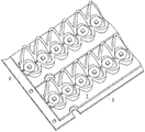
도 1은 본 발명에 따른 조명기구의 구조 개략도,
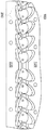
도 2는 리플렉터의 구조 개략도,
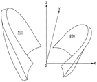
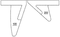
도 3은 반사부의 확대 개략도,
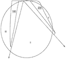
도 4는 본 발명에 따른 반사 유닛의 광로의 확대 개략도,
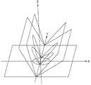
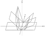
도 5a 및 도 5b는 Y-Z 평면 상에 투사된 자유 곡선의 도면,
도 6a는 자유 곡선의 개략도,
도 6b는 다른 자유 곡선의 개략도,
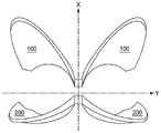
도 7은 본 발명에 따른 리플렉터의 개구부의 개략도,
도 8은 다른 반사부의 확대 개략도,
도 9는 본 발명에 따른 조명기구의 배광 효과도.1 is a structural schematic view of a lighting device according to the present invention,
2 is a schematic view of the structure of the reflector,
3 is an enlarged schematic view of the reflection part,
4 is an enlarged schematic view of an optical path of a reflection unit according to the present invention,
5A and 5B are views of a free-form curve projected on a YZ plane,
6A is a schematic view of a free curve,
6B is a schematic view of another free curve,
7 is a schematic view of an opening of a reflector according to the present invention,
8 is an enlarged schematic view of another reflecting portion,
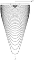
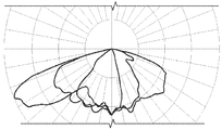
9 is a light distribution effect diagram of a lighting apparatus according to the present invention.
이하, 본 발명의 바람직한 실시예(들)는 유사한 참조 부호는 유사한 요소를 나타내는 첨부 도면과 관련하여 상세하게 설명된다.BRIEF DESCRIPTION OF THE DRAWINGS The preferred embodiment (s) of the present invention will be described in detail below with reference to the accompanying drawings, in which like reference numerals indicate like elements.
본 명세서에 사용된 용어는 특정 실시예를 설명하려는 목적일 뿐이며, 본 발명을 제한할 의도는 아니다. 본 명세서에 사용된 바와 같이, 단수 형태[부정관사("a", "an") 및 정관사("the")]는, 문맥이 명백히 달리 명시하지 않는 한, 복수 형태도 포함하는 것으로 의도된다. 용어 "포함한다" 및/또는 "포함하는" 등은, 본 명세서에서 사용될 때, 언급된 특징부, 요소, 및/또는 구성요소의 존재를 특정하지만, 하나 이상의 다른 특징부, 요소, 구성요소, 및/또는 이들의 그룹의 존재 또는 추가를 배제하지 않는다는 것이 또한 이해될 것이다.The terminology used herein is for the purpose of describing particular embodiments only and is not intended to be limiting of the invention. As used herein, the singular forms "a", "an", and "the" are intended to include the plural forms as well, unless the context clearly dictates otherwise. The term " comprises "and / or" comprising ", when used in this specification, specify the presence of stated features, elements, and / or components but also include the presence of one or more other features, And / or the presence or addition of groups thereof.
도 1은 본 발명에 따른 조명기구의 구조 개략도이다. 도 2는 리플렉터의 구조 개략도이다. 도 3은 반사부의 확대 개략도이다. 1 is a schematic structural view of a lighting apparatus according to the present invention. 2 is a schematic view of the structure of the reflector. 3 is an enlarged schematic view of the reflection part.
이하, 본 발명의 조명기구, 리플렉터 및 반사 부재는 도 1 및 도 2와 관련하여 설명된다.Hereinafter, the illuminator, the reflector and the reflecting member of the present invention will be described with reference to Figs. 1 and 2. Fig.
도 1 내지 도 3에 도시된 바와 같이, 조명기구는 리플렉터(1), 광원(2), 방열판(도시하지 않음) 및 베이스판(3)을 포함한다. 방열판은 베이스판(3)에 고정되고, 리플렉터(1)는 방열판 또는 베이스판(3)에 고정되며, 광원(2)은 방열판에 고정되고 반사 유닛의 광학 중심에 위치되고, 그에 따라 광원으로부터 방출된 광의 일 부분은 개구부를 직접 통과하고, 광의 다른 부분은 리플렉터(1)에 의해 반사된 후에 개구부를 통과한다. 광원(2)은 LED 램프일 수도 있다.1 to 3, the lighting apparatus includes a reflector 1, a
리플렉터(1)는 반사 부재 쌍을 포함하고, 반사 부재의 각 쌍은 제 1 반사부(100), 제 2 반사부(200), 제 1 고정부(120) 및 제 2 고정부(220)를 각각 포함하는 적어도 하나의 반사 유닛을 포함한다. 제 1 고정부(120)는 제 1 반사부(100)의 하단부에 연결되고, 제 2 고정부(220)는 제 2 반사부(200)의 하단부에 연결된다. 제 1 고정부(120) 및 제 2 고정부(220)는 방열판 또는 베이스판(3)에 고정되고, 광원(2)은 방열판에 고정되고 반사 유닛의 광학 중심에 위치된다.The reflector 1 includes a pair of reflecting members and each pair of the reflecting members includes a first reflecting
제 1 고정부(120)는 반사 유닛의 광학 중심에 반대인 제 1 반사부(100)의 측부 상에 위치되고, 제 2 고정부(220)는 반사 유닛의 광학 중심에 반대인 제 2 반사부(200)의 측부 상에 위치된다. 제 1 반사부(100) 및 제 2 반사부(200)는 그들의 하단부로부터 상단부로 테이퍼지게 연장되는 아크 곡면의 형상을 갖고 개구부를 형성하며, 그에 따라 반사 유닛의 광학 중심에 위치된 광원(2)으로부터 방출된 광의 일 부분이 개구부를 직접 통과하고, 광의 다른 부분이 제 1 및 제 2 반사부(100, 200)에 의해 반사된 후에 개구부를 통과한다.The
도 1 및 도 2에 도시된 바와 같이, 반사 부재의 각 쌍은 몇 개의 반사 유닛을 포함하고, 이 반사 유닛 각각은 서로 연결된 각각의 제 1 고정부(120) 및 서로 연결된 각각의 제 2 고정부(220)를 구비한다. 복수의 반사 유닛은 반사 유닛의 광학 중심에 위치된 광원이 일렬로 배열되도록 구성된다. 본 발명은 도 1 및 도 2에 도시된 개수에 한정되지 않고, 당업자는 반사 유닛의 개수를 실제 상황에 따라 하나 이상으로 설정할 수도 있다.As shown in Figs. 1 and 2, each pair of reflecting members includes several reflecting units, and each of the reflecting units has a first
도 1에 도시된 바와 같이, 리플렉터(1)는 반사 유닛의 광학 중심에 위치된 광원이 병렬로 배열되도록 구성되는 2쌍의 반사 부재를 포함한다. 반사 부재는 반사 유닛의 광학 중심에 위치된 광원이 도 1에서 병렬로 배열되도록 구성되어 있지만, 반사 부재는 또한 광원이 일렬로 배열되도록 구성될 수도 있다는 것에 유의해야 한다.As shown in Fig. 1, the reflector 1 includes two pairs of reflecting members arranged so that the light sources positioned at the optical center of the reflecting unit are arranged in parallel. It should be noted that the reflecting members are configured such that the light sources located in the optical center of the reflecting unit are arranged in parallel in Fig. 1, but the reflecting members may also be arranged so that the light sources are arranged in a line.
도 1에 도시된 조명기구가 2개의 리플렉터를 포함하지만, 당업자는 하나의 리플렉터 또는 2개 이상의 리플렉터를 포함하는 것과 같이, 실제 요구에 따라 리플렉터의 개수를 결정할 수도 있다는 것에 유의해야 한다.It should be noted that although the luminaire shown in Fig. 1 includes two reflectors, one of ordinary skill in the art may determine the number of reflectors according to actual needs, such as including one reflector or two or more reflectors.
도 1에 도시된 바와 같이, 복수의 반사 유닛의 형상은 동일할 수도 있다. 그러나, 본 발명에서 복수의 반사 유닛의 형상은 상이할 수도 있다.As shown in Fig. 1, the shapes of the plurality of reflection units may be the same. However, in the present invention, the shapes of the plurality of reflection units may be different.
도 3에 도시된 바와 같이, X축, Y축, Z축이 서로 수직이고, 원점(O)이 광학 유닛의 광학 중심에 위치되는 방식으로 X축, Y축, Z축 및 원점(O)이 정의된다. Y축은 반사 유닛의 광학 중심을 통과하는 축이고, X-Y 평면은 제 1 반사부(100) 및 제 2 반사부(200)의 바닥면을 구성한다.3, the X-axis, the Y-axis, the Z-axis, and the origin (O) are arranged in such a manner that the X-axis, the Y-axis and the Z-axis are perpendicular to each other and the origin O is located at the optical center of the optical unit Is defined. The Y-axis is an axis passing through the optical center of the reflection unit, and the X-Y plane constitutes the bottom surface of the
도 4는 본 발명에 따른 반사 유닛의 광 조사의 확대 개략도이다. 도면에 도시된 바와 같이, X-Y 평면 상에서 Z축 방향으로, 부분 Ⅱ으로부터의 광은 전혀 차단되지 않고 조사될 영역 상에 투사되고, 부분 Ⅰ 및 부분 Ⅲ으로부터의 광은 제 1 반사부(100) 및 제 2 반사부(200)에 의해 반사된 후에 조사될 영역 상에 균일하게 투사된다.4 is an enlarged schematic view of light irradiation of the reflection unit according to the present invention. As shown in the figure, in the Z-axis direction on the XY plane, the light from Part II is projected onto the region to be irradiated without being blocked at all, and the light from Part I and Part III is reflected by the
그러므로, 본 발명의 광 효율은 극히 높다. 조명 영역에 직접 조사 가능한 광은 최대 범위까지 리플렉터를 거치지 않고 직접 방출될 수도 있고, 조명 영역에 직접 조사 가능하지 않는 광은 반사되는 것에 의해서만 조명 영역에 도달할 수 있다.Therefore, the light efficiency of the present invention is extremely high. Light that can be directly irradiated to the illumination region may be emitted directly without passing through the reflector to the maximum extent, and light that can not be directly irradiated to the illumination region may reach the illumination region only by being reflected.
반사부(100, 200)의 아크 곡면 형상은 자유 곡면 형상이다. 도 5a 및 도 5b는 Y-Z 평면 상에 투사된 자유 곡선의 도면이다. 도 6a는 도 5a의 자유 곡선의 개략도이다. 도 6b는 다른 자유 곡선의 개략도이다.The arc curved surface shape of the
도 5a, 도 5b 및 도 6a에 도시된 바와 같이, 자유 곡면은 Y축을 통과하는 평면 그룹 상의 자유 곡선에 의해 형성된다. 도 5a 및 도 6a에 도시된 바와 같이, 자유 곡면은 Y축을 통과하는 평면 그룹 상의 자유 곡선에 의해 형성되고, 자유 곡선은 Z축에 대해 대칭이다. 도 5a와 비교하면, 도 5b에 도시된 자유 곡면은 Y축을 통과하는 평면 그룹 상의 자유 곡선에 의해 형성되고, 자유 곡선은 Z축에 대해 비대칭이다.As shown in Figs. 5A, 5B and 6A, the free-form surface is formed by a free-form curve on a group of planes passing through the Y-axis. As shown in Figs. 5A and 6A, the free-form surface is formed by a free-form curve on a group of planes passing through the Y-axis, and the free-form curve is symmetrical about the Z-axis. 5A, the free-form surface shown in FIG. 5B is formed by a free-form curve on a group of planes passing through the Y-axis, and the free-form curve is asymmetric with respect to the Z-axis.
도 6b는 다른 자유 곡선의 개략도이다. 도 6b에 도시된 바와 같이, 자유 곡면은 Y축을 통과하는 평면 그룹 상의 복수의 직선에 의해 형성되고, 직선은 자유 곡선을 따라 정렬되어 자유 곡면을 형성한다.6B is a schematic view of another free curve. As shown in Fig. 6B, the free-form surface is formed by a plurality of straight lines on a group of planes passing through the Y-axis, and the straight line is aligned along the free-form curve to form a free-form surface.
도 7은 본 발명에 따른 리플렉터의 개구부의 개략도이고, 본 발명의 당업자는 배광의 유형 Ⅰ 내지 유형 Ⅳ에 맞추기 위해, 실제 요구에 따라[즉, 도로 폭 대 램프 스템(lamp stem) 높이의 비율에 따라] 개구부의 사이즈를 조정할 수도 있다. 배광의 유형 Ⅰ은 도로 폭이 램프 스템 높이보다 작은 좁은 도로에 맞춰지고; 배광의 유형 Ⅳ은 도로 폭이 램프 스템 높이보다 2.25배보다 큰 매우 넓은 도로에 맞춰진다. 도면에 도시된 바와 같이, 리플렉터의 반사부(100, 200)의 개구부는 30° 내지 120°의 임의의 각도일 수도 있다.7 is a schematic view of an opening of a reflector according to the present invention, and a person of ordinary skill in the art will appreciate that, in order to match Type I to Type IV of the light distribution, the ratio of the height of the lamp stem Thereby adjusting the size of the opening. Type I light distribution is adapted to a narrow road whose road width is less than the height of the ramp stem; Type IV of light distribution is fitted on very wide roads whose road width is greater than 2.25 times the height of the ramp stem. As shown in the figure, the openings of the
그러므로, 본 발명의 배광 형태는 다양하다. 직접적인 출력광 및 반사된 광은 중첩 매칭의 상이한 형태에 따라 다양한 노면을 위한 배광에 맞춰지는 가요성 배광 형태를 달성한다.Therefore, the light distribution pattern of the present invention is various. The direct output light and the reflected light achieve a flexible light distribution pattern that is tailored to the light distribution for various road surfaces according to different forms of superposition matching.
대안적으로, 제 1 반사부(100) 및 제 1 고정부(120)는 일체형으로 형성될 수도 있고, 또한 제 2 반사부(200) 및 제 2 고정부(220)는 일체형으로 형성될 수도 있다.Alternatively, the first reflecting
대안적으로, 반사부(100, 200)는 소정 간격으로 분포된다. 도면에 도시된 실시예에서 반사부가 동일한 간격으로 분포되는 것으로 도시되어 있지만, 본 발명은 이에 한정되지 않으며, 반사부는 또한 동일하지 않은 간격으로 분포될 수도 있다. 당업자는 실제 요구에 따라 반사부 사이의 간격을 조정할 수도 있다.Alternatively, the
도 1에 도시된 바와 같이, 제 1 반사부(100)의 형상 및 제 2 반사부(200)의 형상은 상이하다. 대안적으로, 도 2에 도시된 바와 같이, 제 1 반사부(100)의 형상 및 제 2 반사부(200)의 형상은 또한 동일할 수도 있다.As shown in FIG. 1, the shape of the
도 8은 반사부의 다른 구조 개략도이다. 도면에 도시된 바와 같이, 반사부(100, 200)는 미러 대칭이다.8 is another schematic structural view of the reflector. As shown in the figure, the
대안적으로, 본 발명에 따른 조명기구는 리플렉터 및 광원을 수용하기 위해 베이스판 또는 방열판에 고정되는 투명 케이싱(도시하지 않음)을 더 포함할 수도 있다.Alternatively, the lighting apparatus according to the present invention may further include a transparent casing (not shown) fixed to the base plate or the heat sink to receive the reflector and the light source.
도 9는 본 발명에 따른 조명기구의 배광 효과도로서, 조명기구의 광 세기 분포(light intensity distribution)를 나타낸다. 일반적으로, 본 발명에 따른 조명기구의 광 효율은 (투명 케이싱의 소실을 고려하지 않고) 실시에 의해 94.5% 내지 97.5%인 것으로 판명되었다. 이것은 광원으로부터 방출된 광을 효율적으로 사용하게 한다.FIG. 9 is a light distribution effect diagram of a lighting apparatus according to the present invention, which shows a light intensity distribution of a lighting apparatus. In general, the light efficiency of the lighting device according to the present invention has been found to be 94.5% to 97.5% by practice (without considering loss of the transparent casing). This allows efficient use of the light emitted from the light source.
본 발명에 따른 조명기구는 도로 조명, 터널 조명 및 편장형 영역 조명에 사용될 수 있지만, 이에 한정되지 않는다. 편장형의 영역은 가구, 슈퍼마켓 선반, 복도, 지하 주차장 또는 철도를 포함하지만, 이에 한정되지 않는다.The luminaire according to the present invention can be used for road lighting, tunnel illumination and circular area illumination, but is not limited thereto. The flattened area includes, but is not limited to, furniture, supermarket shelves, corridors, underground parking lots or railroads.
이러한 개시내용의 관점에서, 본 발명의 다른 실시예, 조합 및 수정이 당업자에게 명백해질 것이다. 그러므로, 본 발명은 상기 설명 및 도면과 관련하여 읽을 때, 특허청구범위에 의해서만 규정된다.
In view of this disclosure, other embodiments, combinations and modifications of the present invention will become apparent to those skilled in the art. Therefore, the present invention is defined only by the appended claims when read in conjunction with the above description and drawings.
Claims (11)
반사 부재 쌍을 포함하고, 반사 부재의 각 쌍은 적어도 하나의 반사 유닛을 포함하고, 각 반사 유닛은 제 1 반사부, 제 2 반사부, 및 하단부가 상기 제 1 반사부 및 제 2 반사부에 각각 연결되는 제 1 고정부 및 제 2 고정부를 포함하고, 상기 제 1 고정부는 상기 반사 유닛의 광학 중심에 반대인 상기 제 1 반사부의 측부 상에 위치되고, 상기 제 2 고정부는 상기 반사 유닛의 광학 중심에 반대인 상기 제 2 반사부의 측부 상에 위치되며, 상기 제 1 반사부 및 제 2 반사부는 하단부로부터 상단부로 테이퍼지게 연장되는 아크 곡면의 형상을 갖고, 개구부를 형성하며, 그에 따라 상기 반사 유닛 내측의 광학 중심에 위치된 광원으로부터 방출된 광의 일 부분은 상기 개구부를 직접 통과하고, 광의 다른 부분은 상기 반사부에 의해 반사된 후에 상기 개구부를 통과하는
리플렉터.In the reflector,
And each pair of reflecting members includes at least one reflecting unit, and each of the reflecting units includes a first reflecting portion, a second reflecting portion, and a lower end portion, which are arranged on the first reflecting portion and the second reflecting portion, Wherein the first fixing part is located on the side of the first reflecting part opposite to the optical center of the reflecting unit and the second fixing part is located on the side of the reflecting unit The first reflecting portion and the second reflecting portion having an arc curved surface shape tapering from a lower end portion to an upper end portion to form an opening portion, A part of the light emitted from the light source located at the optical center of the inside of the unit passes directly through the opening and the other part of the light passes through the opening after being reflected by the reflecting part
Reflector.
상기 아크 곡면 형상은 자유 곡면 형상인
리플렉터.The method according to claim 1,
The arc curved surface shape is a free curved surface shape
Reflector.
상기 자유 곡면은 광축을 통과하는 평면 그룹 상의 자유 곡선에 의해 형성되고, 상기 광축은 상기 반사 유닛의 광학 중심을 통과하는 축인
리플렉터.3. The method of claim 2,
The free-form surface is formed by a free-form curve on a plane group passing through the optical axis, and the optical axis is an axis passing through the optical center of the reflection unit
Reflector.
상기 자유 곡면은 광축을 통과하는 평면 그룹 상의 직선에 의해 형성되고, 상기 광축은 상기 반사 유닛의 광학 중심을 통과하는 축이고, 상기 직선은 자유 곡선을 따라 정렬되어 상기 자유 곡면을 형성하는
리플렉터.3. The method of claim 2,
Wherein the free-form surface is formed by a straight line on a plane group passing through an optical axis, the optical axis is an axis passing through an optical center of the reflecting unit, and the straight line is aligned along a free-
Reflector.
반사 부재의 각 쌍은 복수의 반사 유닛을 포함하고, 상기 복수의 반사 유닛의 제 1 고정부는 서로 연결되고 상기 복수의 반사 유닛의 제 2 고정부는 서로 연결되며, 상기 복수의 반사 유닛은 상기 반사 유닛의 광학 중심에 위치된 광원이 일렬로 배열되도록 구성되는
리플렉터.5. The method according to any one of claims 1 to 4,
Wherein each pair of reflecting members includes a plurality of reflecting units, the first holding parts of the plurality of reflecting units are connected to each other and the second holding parts of the plurality of reflecting units are connected to each other, The light sources positioned in the optical center of the light source
Reflector.
상기 리플렉터는 상기 반사 유닛의 광학 중심에 위치된 광원이 병렬로 또는 일렬로 배열되도록 구성되는 복수 쌍의 반사 부재를 포함하는
리플렉터.5. The method according to any one of claims 1 to 4,
Wherein the reflector comprises a plurality of pairs of reflective members arranged such that light sources located in the optical center of the reflective unit are arranged in parallel or in series
Reflector.
상기 반사부의 개구부는 30° 내지 120°의 임의의 각도일 수 있는
리플렉터.5. The method according to any one of claims 1 to 4,
The opening of the reflecting portion may be any angle of 30 [deg.] To 120 [
Reflector.
상기 방열판은 상기 베이스판에 고정되고, 상기 제 1 고정부 및 제 2 고정부는 상기 방열판 또는 상기 베이스판에 고정되며,
상기 광원은 상기 방열판에 고정되고 상기 반사 유닛의 광학 중심에 위치되고, 그에 따라 상기 광원으로부터 방출된 광의 일 부분이 개구부를 직접 통과하고, 광의 다른 부분이 상기 제 1 반사부 및 제 2 반사부에 의해 반사된 후에 상기 개구부를 통과하는A lighting fixture comprising a heat sink, a base plate, a light source, and a reflector according to any one of claims 1 to 7,
Wherein the heat sink is fixed to the base plate, the first fixing part and the second fixing part are fixed to the heat sink or the base plate,
Wherein the light source is fixed to the heat sink and is located at the optical center of the reflective unit so that a portion of the light emitted from the light source passes directly through the opening and another portion of the light is transmitted through the first and second reflectors And after passing through the opening
상기 조명기구는 상기 광원 및 상기 리플렉터를 수용하기 위해 상기 베이스판 또는 방열판에 고정되는 투명 케이싱을 더 포함하는
조명기구.9. The method of claim 8,
The illuminator further includes a transparent casing fixed to the base plate or the heat sink to receive the light source and the reflector
Lighting fixtures.
상기 광원은 LED 램프인
조명기구.10. The method according to claim 8 or 9,
The light source is an LED lamp
Lighting fixtures.
상기 조명기구는 도로 조명, 터널 조명 및 편장형 영역 조명에 사용되는
조명기구의 용도.
10. Use of a lighting device according to any one of claims 8 to 10,
The luminaire is used for street lighting, tunnel lighting and circular area lighting
Use of lighting fixtures.
Applications Claiming Priority (3)
| Application Number | Priority Date | Filing Date | Title |
|---|---|---|---|
| CN201110342006.3A CN103062709B (en) | 2011-10-19 | 2011-10-19 | Reflector, luminaire and application thereof |
| CN201110342006.3 | 2011-10-19 | ||
| PCT/US2012/060969 WO2013059557A1 (en) | 2011-10-19 | 2012-10-19 | Reflector, illuminator and the use thereof |
Publications (1)
| Publication Number | Publication Date |
|---|---|
| KR20140082707A true KR20140082707A (en) | 2014-07-02 |
Family
ID=47192109
Family Applications (1)
| Application Number | Title | Priority Date | Filing Date |
|---|---|---|---|
| KR1020147010319A KR20140082707A (en) | 2011-10-19 | 2012-10-19 | Reflector, illuminator and the use thereof |
Country Status (11)
| Country | Link |
|---|---|
| US (1) | US9086204B2 (en) |
| EP (1) | EP2769141A1 (en) |
| JP (1) | JP6093365B2 (en) |
| KR (1) | KR20140082707A (en) |
| CN (1) | CN103062709B (en) |
| AU (1) | AU2012325969B2 (en) |
| BR (1) | BR112014009476A2 (en) |
| CA (1) | CA2852083C (en) |
| CO (1) | CO6920284A2 (en) |
| MX (1) | MX337388B (en) |
| WO (1) | WO2013059557A1 (en) |
Families Citing this family (11)
| Publication number | Priority date | Publication date | Assignee | Title |
|---|---|---|---|---|
| JP6263768B2 (en) * | 2013-11-05 | 2018-01-24 | 岩崎電気株式会社 | Light emitting element unit and lighting apparatus |
| USD740999S1 (en) * | 2014-05-16 | 2015-10-13 | Ningbo Yinzhou Self Photoelectron Technology Co., Ltd. | Lighthead lens |
| USD740471S1 (en) * | 2014-05-16 | 2015-10-06 | Ningbo Yinzhou Self Photoelectron Technology Co., Ltd. | Lighthead |
| CN104197276A (en) * | 2014-09-12 | 2014-12-10 | 宁波燎原灯具股份有限公司 | LED (light emitting diode) asymmetric light distributing device and LED lamp with same |
| KR101679673B1 (en) | 2016-05-16 | 2016-11-25 | 주식회사 창우 | Illuminating light for roadway lighting |
| US11488501B2 (en) * | 2016-11-10 | 2022-11-01 | Media Resources Inc. | System, method and apparatus for directed LED display |
| TWI615581B (en) * | 2017-07-14 | 2018-02-21 | 達運精密工業股份有限公司 | Light reflective cover and illumination apparatus having the same |
| IT201900010809A1 (en) * | 2019-07-03 | 2021-01-03 | Aec Illuminazione S R L | LIGHTING MODULE, PROJECTOR OBTAINED WITH THIS MODULE AND RELATED LIGHTING ARCHITECTURE |
| CN111256092B (en) * | 2020-01-19 | 2022-04-26 | 杭州宇中高虹照明电器有限公司 | Anisotropic grid and anisotropic grid lamp |
| JP7453092B2 (en) * | 2020-08-19 | 2024-03-19 | 株式会社遠藤照明 | lighting equipment |
| US11333805B1 (en) * | 2021-05-14 | 2022-05-17 | Vode Lighting, LLC | Low glare luminaires |
Citations (5)
| Publication number | Priority date | Publication date | Assignee | Title |
|---|---|---|---|---|
| US4593485A (en) * | 1983-05-30 | 1986-06-10 | U.S. Philips Corporation | Display panel having semiconductors crystals |
| US20060035511A1 (en) * | 2004-04-06 | 2006-02-16 | Gelcore Llc | Flexible high-power LED lighting system |
| CN101782213A (en) * | 2009-01-16 | 2010-07-21 | 奥斯兰姆有限公司 | Side reverse-type reflector |
| KR100986736B1 (en) * | 2009-12-23 | 2010-10-08 | 황남극 | A street lighting equipment for flexible light distribution |
| CN102216677A (en) * | 2008-09-16 | 2011-10-12 | 马斯科公司 | Method, system and apparatus for highly controlled light distribution from light fixture using multiple light sources (led's) |
Family Cites Families (8)
| Publication number | Priority date | Publication date | Assignee | Title |
|---|---|---|---|---|
| EP1151227B1 (en) * | 1999-11-12 | 2008-02-06 | Koninklijke Philips Electronics N.V. | Luminaire without lamellae |
| US7008079B2 (en) * | 2003-11-21 | 2006-03-07 | Whelen Engineering Company, Inc. | Composite reflecting surface for linear LED array |
| AU2006235806B2 (en) * | 2005-10-26 | 2011-12-08 | Pentair Water Pool And Spa, Inc. | LED pool and spa light |
| CN201072071Y (en) | 2007-08-17 | 2008-06-11 | 浙江求是信息电子有限公司 | Grille type LED road lamp reflector |
| JP5263658B2 (en) * | 2007-11-30 | 2013-08-14 | 東芝ライテック株式会社 | Lighting device |
| CN101545609B (en) * | 2008-03-25 | 2010-09-29 | 山西光宇电源有限公司 | Multi-surface reflector for LED street lamp |
| CN201246677Y (en) | 2008-07-16 | 2009-05-27 | 厦门华联电子有限公司 | Reflection shield of LED road lamp |
| CN101446404A (en) | 2008-12-29 | 2009-06-03 | 浙江晶日照明科技有限公司 | LED road lamp and illuminating light-regulating method therefor |
-
2011
- 2011-10-19 CN CN201110342006.3A patent/CN103062709B/en not_active Expired - Fee Related
-
2012
- 2012-10-19 MX MX2014004684A patent/MX337388B/en active IP Right Grant
- 2012-10-19 AU AU2012325969A patent/AU2012325969B2/en not_active Ceased
- 2012-10-19 WO PCT/US2012/060969 patent/WO2013059557A1/en active Application Filing
- 2012-10-19 US US14/352,166 patent/US9086204B2/en not_active Expired - Fee Related
- 2012-10-19 EP EP12787959.1A patent/EP2769141A1/en not_active Withdrawn
- 2012-10-19 BR BR112014009476A patent/BR112014009476A2/en not_active Application Discontinuation
- 2012-10-19 JP JP2014537272A patent/JP6093365B2/en not_active Expired - Fee Related
- 2012-10-19 KR KR1020147010319A patent/KR20140082707A/en not_active Application Discontinuation
- 2012-10-19 CA CA2852083A patent/CA2852083C/en not_active Expired - Fee Related
-
2014
- 2014-04-04 CO CO14072655A patent/CO6920284A2/en unknown
Patent Citations (5)
| Publication number | Priority date | Publication date | Assignee | Title |
|---|---|---|---|---|
| US4593485A (en) * | 1983-05-30 | 1986-06-10 | U.S. Philips Corporation | Display panel having semiconductors crystals |
| US20060035511A1 (en) * | 2004-04-06 | 2006-02-16 | Gelcore Llc | Flexible high-power LED lighting system |
| CN102216677A (en) * | 2008-09-16 | 2011-10-12 | 马斯科公司 | Method, system and apparatus for highly controlled light distribution from light fixture using multiple light sources (led's) |
| CN101782213A (en) * | 2009-01-16 | 2010-07-21 | 奥斯兰姆有限公司 | Side reverse-type reflector |
| KR100986736B1 (en) * | 2009-12-23 | 2010-10-08 | 황남극 | A street lighting equipment for flexible light distribution |
Also Published As
| Publication number | Publication date |
|---|---|
| AU2012325969A1 (en) | 2014-05-01 |
| US9086204B2 (en) | 2015-07-21 |
| JP6093365B2 (en) | 2017-03-08 |
| CN103062709A (en) | 2013-04-24 |
| CA2852083A1 (en) | 2013-04-25 |
| CA2852083C (en) | 2019-12-31 |
| CO6920284A2 (en) | 2014-04-10 |
| US20150009668A1 (en) | 2015-01-08 |
| AU2012325969B2 (en) | 2015-07-02 |
| JP2015505413A (en) | 2015-02-19 |
| BR112014009476A2 (en) | 2017-06-13 |
| MX2014004684A (en) | 2015-02-05 |
| WO2013059557A1 (en) | 2013-04-25 |
| EP2769141A1 (en) | 2014-08-27 |
| CN103062709B (en) | 2016-08-24 |
| MX337388B (en) | 2016-03-02 |
Similar Documents
| Publication | Publication Date | Title |
|---|---|---|
| KR20140082707A (en) | Reflector, illuminator and the use thereof | |
| JP4017655B2 (en) | Lighting device and lighting system | |
| TWI404881B (en) | Illumination module | |
| CN202403190U (en) | Asymmetrical light distribution structure of LED projection lamp | |
| KR100900953B1 (en) | Street light | |
| CN202140974U (en) | Anti-dazzling LED (light-emitting diode) lens and lamp | |
| WO2009030121A1 (en) | A led lamp | |
| JP2008130393A (en) | Lighting system, and illumination system | |
| CN101561087A (en) | LED flat light source structure | |
| KR20100030339A (en) | Illuminator module using led | |
| CN201462499U (en) | LED planar light source structure | |
| KR101073473B1 (en) | Uniformity factor of intensity of illumination improved holding frame for led and lighting apparatus for street lamp using the same | |
| KR20090011424U (en) | LED lamp street light | |
| CN202040632U (en) | LED plane light source device | |
| JP2014503111A (en) | Lighting device and lighting fixture having the lighting device | |
| KR101511664B1 (en) | lighting source module for medical treatment | |
| KR101144750B1 (en) | Led lighting device having rectangular light distribution | |
| RU2533770C2 (en) | Lighting module and lighting device comprising variety of such lighting modules | |
| CN101943355A (en) | LED streetlight unit | |
| CN105444118B (en) | A kind of lens and the LED ground footlight with the lens | |
| TWM457133U (en) | Off-axis optical lens, off-axis optical plate and lighting device, illuminating lamp device for outdoors | |
| CN202561464U (en) | Reflective type LED illuminating lamp | |
| KR101128957B1 (en) | led flat panels with individual Reflector. | |
| CN201028363Y (en) | LED oriented lighting energy-saving lamp | |
| TWI535979B (en) | Led light source module and led street light |
Legal Events
| Date | Code | Title | Description |
|---|---|---|---|
| A201 | Request for examination | ||
| E902 | Notification of reason for refusal | ||
| E601 | Decision to refuse application |