JP6263768B2 - Light emitting element unit and lighting apparatus - Google Patents
Light emitting element unit and lighting apparatus Download PDFInfo
- Publication number
- JP6263768B2 JP6263768B2 JP2013229485A JP2013229485A JP6263768B2 JP 6263768 B2 JP6263768 B2 JP 6263768B2 JP 2013229485 A JP2013229485 A JP 2013229485A JP 2013229485 A JP2013229485 A JP 2013229485A JP 6263768 B2 JP6263768 B2 JP 6263768B2
- Authority
- JP
- Japan
- Prior art keywords
- optical axis
- light
- light source
- light emitting
- reflecting plate
- Prior art date
- Legal status (The legal status is an assumption and is not a legal conclusion. Google has not performed a legal analysis and makes no representation as to the accuracy of the status listed.)
- Expired - Fee Related
Links
Images


Description
本発明は、発光素子を光源に備えた発光素子ユニット、及び照明器具に関する。 The present invention relates to a light emitting element unit including a light emitting element as a light source, and a lighting fixture.
道路用(トンネル用を含む)の照明器具では、LEDの高輝度化に伴いLEDを光源とした器具が開発されている。この種の照明器具の光源は、一般に、複数個のLEDを基板に並べて構成されている(例えば、特許文献1参照)。このLEDは、個々に1個の回路部品として扱われ、互いに独立して発光制御可能なデバイスであり、反射面内にLED素子を配置した表面実装型LED等が好適に用いられている。 With respect to lighting fixtures for roads (including those for tunnels), fixtures using LEDs as light sources have been developed as the brightness of LEDs increases. A light source of this type of lighting fixture is generally configured by arranging a plurality of LEDs on a substrate (see, for example, Patent Document 1). This LED is a device that can be individually handled as one circuit component and can control light emission independently of each other, and a surface-mounted LED or the like in which an LED element is arranged in a reflecting surface is preferably used.
しかしながら、上記従来の構成では、道路の形状に応じた光度軸を個々のデバイスに持たせることは困難である。そこでアクリルなどの樹脂製レンズを設けて配光制御することも考えられる。
しかしながら、より大光量が必要とされる用途において光源に高出力の発光素子モジュールを用いる場合には、当該発光素子モジュールは発熱量が多くレンズが高温となるため、レンズ材の変形や物性変化などの不具合を生じやすくなるので、アクリルなどの耐熱温度が比較的低い汎用樹脂製レンズを用いることができない。また高出力の発光素子モジュールに代えて、発光素子及びレンズを多数設けて大光量を実現する場合には、部品点数及びコストが増加してしまう。
However, with the above-described conventional configuration, it is difficult to give each device a luminous intensity axis corresponding to the shape of the road. Therefore, it is possible to control the light distribution by providing a resin lens such as acrylic.
However, when a high-power light-emitting element module is used as a light source in an application where a larger amount of light is required, the light-emitting element module generates a large amount of heat and the lens becomes high temperature. Therefore, it is not possible to use a general-purpose resin lens having a relatively low heat-resistant temperature such as acrylic. Further, when a large amount of light is realized by providing a large number of light emitting elements and lenses instead of the high output light emitting element module, the number of parts and the cost increase.
本発明は、上述した事情に鑑みてなされたものであり、良好な放熱性を有し、かつ光度軸の設計が容易な発光素子ユニット、及び照明器具を提供することを目的とする。 This invention is made | formed in view of the situation mentioned above, It aims at providing the light emitting element unit which has favorable heat dissipation, and the design of a luminous intensity axis is easy, and a lighting fixture.
上記目的を達成するために、本発明は、複数の発光素子を含む面状光源と、前記面状光源を挟んで対面配置される上反射板、及び下反射板と、を備え、前記面状光源の直射光と、前記上反射板、及び前記下反射板による反射光とで、前記上反射板、及び前記下反射板が対面する第1方向と直交する第2方向に延びる照射領域を照射し、前記上反射板、及び前記下反射板の反射面は、前記面状光源の光軸の基点を挟んだ2つの方向に設定された回転放物面の一部であり、前記回転放物面のそれぞれは、前記面状光源の光軸の基点から当該光軸と異なる方向に延びる軸を中心光軸とし、かつ、平面視において前記回転放物面の底部が前記面状光源の発光面を横断していることを特徴とする発光素子ユニットを提供する。 In order to achieve the above object, the present invention includes a planar light source including a plurality of light emitting elements , and an upper reflecting plate and a lower reflecting plate disposed facing each other with the planar light source interposed therebetween, and the planar shape. Irradiates an irradiation region extending in a second direction orthogonal to the first direction in which the upper reflecting plate and the lower reflecting plate face with direct light of the light source and reflected light from the upper reflecting plate and the lower reflecting plate. The reflecting surfaces of the upper reflecting plate and the lower reflecting plate are a part of a rotating paraboloid set in two directions across a base point of the optical axis of the planar light source, and the rotating paraboloid. Each of the surfaces has a central optical axis that extends from a base point of the optical axis of the planar light source in a direction different from the optical axis, and the bottom of the paraboloid in plan view is the light emitting surface of the planar light source A light emitting element unit characterized by crossing the line is provided.
また本発明は、上記発光素子ユニットにおいて、前記上反射板、及び前記下反射板の反射面の焦点を前記面状光源の発光部の中心に合わせたことを特徴とする。 In the light emitting element unit, the present invention is characterized in that the reflecting surfaces of the upper reflecting plate and the lower reflecting plate are focused on the center of the light emitting portion of the planar light source .
また本発明は、上記発光素子ユニットにおいて、前記上反射板、及び前記下反射板の反射面は、前記中心光軸を同じくしつつ、大きさが異なる複数の前記回転放物面を含むことを特徴とする。 The present invention, in the above-mentioned light-emitting element unit, the upper reflector, and a reflective surface of the lower reflector, while also the central optical axis, that the size comprises a plurality of different rotational paraboloid Features.
また本発明は、上記発光素子ユニットにおいて、前記第2方向において前記面状光源を挟んで配置され、前記面状光源から入射する光を前記第2方向の前記面状光源の側に反射する補助反射面を有し、前記補助反射面のそれぞれは、前記第2方向に延びる軸を中心光軸とした回転放物面の一部から成ることを特徴とする。 According to the present invention, in the light emitting device unit, the auxiliary light source disposed in the second direction with the planar light source interposed therebetween, and reflects light incident from the planar light source toward the planar light source in the second direction. Each of the auxiliary reflecting surfaces includes a part of a rotating paraboloid having an axis extending in the second direction as a central optical axis .
また本発明は、上記のいずれかに記載の発光素子ユニットを光源に備えたことを特徴とする照明器具を提供する。 Moreover, this invention provides the lighting fixture characterized by providing the light emitting element unit in any one of said above in the light source.
また本発明は、上記の照明器具において、前記面状光源からみて前記第2方向の両側のそれぞれに設定された前記回転放物面の中心光軸の鉛直角を異ならせ、それぞれの中心光軸による光度ピーク値に差を持たせたことを特徴とする。
Further, the present invention provides the above-described lighting apparatus, wherein the vertical optical axes of the rotating paraboloid surfaces set on both sides in the second direction as viewed from the planar light source are made different from each other , and the respective central optical axes. It is characterized by having a difference in the luminous intensity peak value due to.
本発明によれば、発光素子の光軸の基点から当該光軸と異なる方向に延びる軸を中心光軸とする反射鏡の反射面を、回転放物面の一部で形成したため、回転放物面の中心光軸に基づく光度軸の設計が容易となる。また反射面により配光を制御するからレンズ等の透過型光学系に比べて良好な放熱性が得られる。 According to the present invention, the reflecting surface of the reflecting mirror whose central optical axis is an axis extending in a direction different from the optical axis from the optical axis base point of the light emitting element is formed as a part of the rotating paraboloid. The light intensity axis can be easily designed based on the center optical axis of the surface. Further, since the light distribution is controlled by the reflecting surface, better heat dissipation can be obtained as compared with a transmissive optical system such as a lens.
以下、図面を参照して本発明の実施形態について説明する。
[LEDユニット]
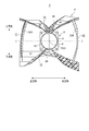
図1は本実施形態に係るLEDユニット1の正面図である。
LEDユニット1は、これらの図に示すように、大別すると、光源たるLEDモジュール2と、このLEDモジュール2の周囲を囲む反射鏡4とを備え、LEDモジュール2の直射光と、反射鏡4の反射光とによって、左右に長い横長の照射野を照射する、いわゆる横長配光を有する。
LEDモジュール2は、実装基板たる矩形板状のLED基板6と、このLED基板6に実装されたLEDチップ8とを備えている。LED基板6の材質は、LEDチップ8の投入電力、及び発熱量に基づいて、このLEDチップ8を十分に放熱する熱伝導性、及び電気的な絶縁を図れる電気絶縁性を有する材料から選定されている。例えばLED基板6にはセラミックを基材とした基板、或いはアルミニウム等の金属基板に絶縁皮膜を施した基板が用いられている。
Hereinafter, embodiments of the present invention will be described with reference to the drawings.
[LED unit]
FIG. 1 is a front view of an
As shown in these drawings, the
The
LEDチップ8は、多数のLEDを密集配置して正面視略円形(四角形も有り得る)の面状の発光部10を形成したチップオンボード(COB)構造のLEDデバイスである。この面状の発光部10は、この面に略垂直な方向に光軸Fを有し、この光軸Fの方向に最大ピークを有する、いわゆるランバート出射光度分布を持っている。
一般に、チップオンボード構造のLEDデバイスは、多数のLEDが密集配置されていることから大光量で輝度が高く、光出力も大きい。このようなLEDチップ8を光源に備えることで、大光量のユニットが構成される。
The
In general, an LED device having a chip-on-board structure has a large luminance, a high luminance, and a large light output because a large number of LEDs are densely arranged. By providing such an
この明細書では、光軸Fと発光部10の交点、すなわち発光部10の中心を光軸Fの基点Oと定義する。また、この光軸FをZ軸とし、基点Oを原点とする直交XYZ座標系のX軸の方向を左右方向、Y軸の方向を上下方向と定義する。
In this specification, the intersection of the optical axis F and the
図2は、反射鏡4の構成を示す図であり、図2(A)は正面図、図2(B)は上面図、図2(C)は下面図、図2(D)は左側面図、図2(E)は右側面図、及び図2(F)は背面図である。
反射鏡4は、上述のように、発光部10の上下左右のそれぞれに設けた上反射板15、下反射板16、左反射板17、及び右反射板18を有し、これらによって発光部10の四方が囲まれている。この反射鏡4には、例えば樹脂やアルミダイカスト成型品にアンダーコート、アルミ蒸着、トップコート加工を施したものが用いられており、その反射率は80〜85%程度である。
上反射板15、及び下反射板16は互いに一体となって光軸Fを挟んだ左右の両側に、この光軸Fと異なる方向に延びる光度軸K1、K2を配するための光学部材である。また左反射板17は右側に延びる光度軸K1の光を反射光によって補い、右反射板18は左側に延びる光度軸K2の光を反射光によって補う光学部材である。
2A and 2B are diagrams showing the configuration of the reflecting
As described above, the reflecting
The upper reflecting
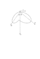
図3はLEDユニット1の配光特性を示す配光曲線の概略図である。なお、この図3には図1のI−I線を含む鉛直面内の配光を示している。
この図に示すように、LEDユニット1は、光軸Fの基点Oから左右の両側に鉛直角α1、α2で延びる光度軸K1、K2を配置した配光特性を有している。このLEDユニット1では、光度軸K1、K2の鉛直角α1、α2、及び光量を異ならせることで、これら光度軸K1、K2の光度ピーク値に差を持たせており、右側の光度軸K1が最大光度軸となり、かつ鉛直角α1>鉛直角α2となるようにLEDモジュール2の配光が制御されている。
なお、光度軸K1、K2の光量、及び、鉛直角α1、α2は、LEDユニット1の用途に応じて適宜に変更可能である。
FIG. 3 is a schematic diagram of a light distribution curve showing the light distribution characteristics of the
As shown in this figure, the
The light amounts of the luminous intensity axes K1 and K2 and the vertical angles α1 and α2 can be changed as appropriate according to the application of the
このLEDユニット1では、反射鏡4の上反射板15、下反射板16、左反射板17、及び右反射板18のそれぞれが、光度軸K1、K2を中心光軸とした回転放物面の一部で形成した反射面を含み、これによって配光に光度軸K1、K2を有するように成されている。
以下、この構成の反射鏡4について更に詳述する。
In this
Hereinafter, the reflecting
上反射板15、及び下反射板16は、図1に示すように、光軸Fの右側に第1光軸形成反射面30、31、32を有し、左側に第2光軸形成反射面40、41、42を有している。
第1光軸形成反射面30、31、32のそれぞれは、光度軸K1を中心光軸とし、互いに大きさが異なる回転放物面H1(図4、図5)から一部を切り出して形成した面形状を成し、また同様に第2光軸形成反射面40、41、42のそれぞれは光度軸K2を中心光軸とし、互いに大きさが異なる回転放物面H2(図4、図5)から一部を切り出して形成した面形状を成している。
As shown in FIG. 1, the
Each of the first optical axis forming reflecting
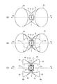
図4、及び図5は第1光軸形成反射面30、31、32、及び第2光軸形成反射面40、41、42の説明図であり、図4は平面視図、図5は斜視図である。なお、これら図4、図5では、発明の理解を容易にするために、光度軸K1、及び光度軸K2を左右対称とした場合を示している。
LEDユニット1では、図4(A)、及び図5(A)に示すように、2本の光度軸K1、K2が発光部10の光軸Fの基点Oから当該光軸Fを挟んで反対方向に延びる。このとき、各光度軸K1、K2を中心光軸とし、かつ放射方向が開放する上述の回転放物面H1、H2を反射鏡とすれば、発光部10の放射光を光度軸K1、K2に2分して出射できる。
さらに回転放物面H1、H2の一部で形成した反射面の焦点を発光部10の中心である基点Oに合わせることで発光部10の放射光が光度軸K1、K2の方向に精度良く反射によって配光される。
係る回転放物面H1、H2をLEDユニット1に設ける際には、図4(B)、及び図5(B)に示すように、LEDモジュール2のLED基板6を含む平面よりも発光部10の側を残すように当該平面と交差する線23に沿って回転放物面H1、H2をカットする。
4 and 5 are explanatory views of the first optical axis forming reflecting
In the
Further, by adjusting the focal point of the reflecting surface formed by a part of the rotating paraboloids H1 and H2 to the base point O that is the center of the
When the rotating paraboloids H1 and H2 are provided in the
図4(B)、及び図5(B)の構成によれば、光度軸K1、K2の2方向をスポット的に照射できるものの、光軸Fの方向は回転放物面H1、H2によって覆い隠されることから例えば道路照明等に用いて好適な横長な配光にはならない。
そこで、このLEDユニット1では、発光部10が露出するように、回転放物面H1、H2の内面が露出するように平面視で開放させている。
According to the configurations of FIGS. 4B and 5B, the two directions of the luminous intensity axes K1 and K2 can be spot-irradiated, but the direction of the optical axis F is covered by the paraboloids H1 and H2. Therefore, for example, the light distribution is not suitable for use in road lighting or the like.
Therefore, in this
すなわち、図4(C)、及び図5(C)に示すように、発光部10を露出させる開放をつくるように、例えばLED基板6に平行な平面で、当該LED基板6から所定の距離離れた位置で当該平面と交差する線24に沿って回転放物面H1、H2をカットする。これにより発光部10が露出することで、2つの光度軸K1、K2で挟まれた光軸Fの方向が発光部10の直射光によって照射されることとなり、横に長い照射野が得られることとなる。
このとき、回転放物面H1から切り出された切出面Maが上下に完全に分離し、同様に回転放物面H2から切り出された切出面Mbが上下に完全に分離するようにカットすることで、横長の照射野の中に影を生じさせることがなく均斉度が高められる。
That is, as shown in FIGS. 4C and 5C, a predetermined distance from the
At this time, the cut surface Ma cut out from the rotary paraboloid H1 is completely separated vertically, and similarly, the cut surface Mb cut from the rotary paraboloid H2 is cut so as to be completely separated vertically. The uniformity is increased without causing shadows in the horizontally long irradiation field.
回転放物面H1の切出面Ma、及び回転放物面H2の切出面Mbの左右の開放端側の端部は、図4(C)、及び図5(C)に示すように、LED基板6に略垂直な平面と交差する線25に沿ってカットされる。このときのカット位置は、例えば配光設計や器具設計に基づき適宜に決定される。
As shown in FIGS. 4 (C) and 5 (C), the left and right open end sides of the cut-out surface Ma of the rotary paraboloid H1 and the cut-out surface Mb of the rotary paraboloid H2 are LED substrates. 6 is cut along a
これら回転放物面H1の切出面Ma、及び回転放物面H2の切出面Mbを、第1光軸形成反射面、及び第2光軸形成反射面として反射鏡4の上反射板15、及び下反射板16に設けることで、LEDモジュール2の放射光が光度軸K1、K2に配光される。
このLEDユニット1では、上反射板15、及び下反射板16には、単一の回転放物面H1、H2から切り出した面だけではなく、中心光軸を同じくしつつ大きさが互いに異なる複数の回転放物面H1、H2から切り出した面を、それぞれ第1光軸形成反射面30、31、32、及び第2光軸形成反射面40、41、42として設けることで、光度軸K1、K2に効率良く光が配光されるようになっている。
さらに、この上反射板15、及び下反射板16には、図1に示すように、照射野の均斉度を高めるように配光制御する配光制御面34、35、36、37が適宜に設けられている。
The
In this
Further, as shown in FIG. 1, the
ここで、回転放物面H1、及び回転放物面H2の切り出し方によっては、図4(C)に示すように、LEDチップ8の発光部10に迫り出して被る突出部27が生じることがある。この構成においては、発光部10から光軸Fに向かって放射される比較的強い光が突出部27で反射されてしまうから、その分、光軸Fの方向の光量(直射光の光量)が低下することになる。また当該反射によって反射率に応じた光量のロスも生じることから、LEDユニット1の効率も低下する。
そこで、この反射鏡4にあっては、図4(C)において発光部10に被る突出部27を、図1に示すように、外側(平面視で発光部10から遠ざかる方向)に向かって凹ませる等して当該発光部10に被らない形状の非突出部28としている。これにより、発光部10から光軸Fに沿って出射された比較的強い光が直接光として照明に利用され、光軸Fの方向の光量低下の抑制、及び効率向上が図られている。
特にLEDユニット1を道路灯の光源とした場合、光軸Fが道路面内方向を向き、路面の目標領域に直達する光は遮らずそのまま利用し、目標領域へ直達しない光は、第1光軸形成反射面30、31、32、及び第2光軸形成反射面40、41、42で進行方向を換え、目標領域へ到達することとなり光学効率の高い光源が実現される。
Here, depending on how to cut the paraboloid H1 and the paraboloid H2, as shown in FIG. 4C, a protruding
Therefore, in the reflecting
In particular, when the
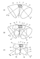
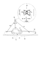
ところで、光度軸K1、K2を作る回転放物面H1、H2の設定に際し、焦点が基点Oに位置する回転放物面は無数に存在する。
例えば、図6に示すように、発光部10を平面視した場合、この発光部10を内側に内包する回転放物面Haと、底部48が発光部10を横断してはみ出す回転放物面Hbとのそれぞれが設定できる。しかしながら、回転放物面Haは、回転放物面Hbよりも大きくなることからLEDユニット1が大型化し、また発光部10の光軸Fからの距離rも遠くなるため、同じ高さにカットした反射面で比較すると、直射領域が道路幅方向に無駄に広くなり、かつ反射光成分も少なくなり、効率が良い配光設計とは言えない。
そこで、このLEDユニット1にあっては、回転放物面H1、H2の設定に際しては、底部48が発光部10を横断するように回転放物面Hbを設定することで、光度軸K1、K2の方向の光量を効率良く高め、かつ小型化を可能にしている。
By the way, when setting the paraboloids H1 and H2 for forming the luminous intensity axes K1 and K2, there are an infinite number of paraboloids whose focal points are located at the base point O.
For example, as shown in FIG. 6, when the
Therefore, in the
前掲図1、及び図2に戻り、反射鏡4の左反射板17、及び右反射板18は、それぞれ左右方向に向かう光を光度軸K1、K2の方向に反射することで光量を補うものである。具体的には、左反射板17は、右方向に延在する光度軸K1を中心光軸とする回転放物面の一部から成る第1光度軸形成補助反射面22Aを有し、同様に右反射板18は、左方向に延在する光度軸K2を中心光軸とした回転放物面の一部から成る第2光度軸形成補助反射面22Bを有する。
第1、及び第2光度軸形成補助反射面22A、22Bの回転放物面H3は、図6に示すように、発光部10の基点Oを焦点とし、中心光軸とする光度軸K1、K2の方向に開放し、少なくとも発光部10を内包する大きさの回転放物面である。
これにより、発光部10から左右に放射される光が第1、及び第2光度軸形成補助反射面22A、22Bによって光度軸K1、K2の方向に反射されて光量が効果的に補われる。
Returning to FIGS. 1 and 2, the
As shown in FIG. 6, the rotating paraboloids H3 of the first and second luminous intensity axis forming
Thereby, the light emitted from the
[トンネル照明器具]
LEDユニット1は、上述の通り、横長な範囲を均斉度よく照射可能であるから、道路照明器具の光源に好適に用いることができる。特に、前掲図3で示すように、このLEDユニット1は、光度軸K1、K2を互いに独立して、かつ、45度を超えるような比較的大きな鉛直角α1、α2に設定できることから、トンネル照明器具の光源に用いて好適である。
[Tunnel lighting equipment]
Since the
図7は、このLEDユニット1を光源に備えたトンネル照明器具50の模式図である。
トンネル照明器具50は、灯具ケース51を備え、この灯具ケース51には、LEDユニット1が左右方向を道路の交通方向Nに合わせて収められる。なお、複数個のLEDユニット1を灯具ケース51に設けても良いことは勿論である。また、灯具ケース51には、LEDユニット1の駆動回路や電源回路など、一般的なトンネル照明器具が備える要素を備えている。
FIG. 7 is a schematic diagram of a
The
トンネル照明器具50は、道路55の路面56を照射するようにトンネルの内壁面(図示せず)に設置される。LEDユニット1は、左右の光度軸K1、K2の鉛直角α1、α2が異なることで、左右非対称の配光を有し、本実施形態では、車両57の進行方向Sに向かう光度軸K1の鉛直角α1が約45°以上に設定され、これと反対方向の光度軸K2の鉛直角α2は約30°程度に設定されることで、いわゆるプロビーム照明が成されている。
The
また光源のLEDユニット1にあっては、上述の通り、左右の光度軸K1、K2の鉛直角α1、α2をそれぞれ独立して設定でき、また路面56に沿った横長の照射範囲58の全域を照射できることから、例えばトンネルへのトンネル照明器具50の取付間隔等に応じて鉛直角α1、α2を自由に設定し、対称や非対称の配光の光源を簡単に構成できる。
Moreover, in the
具体的には、器具取付け間隔を長くできる光源を作る場合、大きな鉛直角で強い光度ヒ一クができるような光学系を光源に設ける必要がある。そこでLEDモジュール2にあっては、LEDチップ8の光軸Fの方向(器具正面方向)に最も高い光束が出ているため、光軸Fの方向に反射面を設け、この反射面の反射光で上記の光度ピークを作れば、比較的容易に光度ピーク値の鉛直角を大きくできる。
しかしながら、この構成では、強度が高い路面直達光を反射面で遮り、反射面吸収による強度低下を伴いながら、同じ路面56のトンネル照明器具50から遠くを照射することとなり、器具全体として光効率が悪くなる。さらに光軸Fの付近の光を遮ると、器具直下への光を完全にカットするため、器具直下の照度が不足する。そこで良好な配光を得るために、他の反射面から器具直下への光を補わなければならなくなり、光利用効率の点では効率が悪い。
Specifically, when making a light source capable of extending the instrument mounting interval, it is necessary to provide the light source with an optical system capable of producing a strong luminous intensity with a large vertical angle. Therefore, in the
However, in this configuration, high-intensity road surface direct light is blocked by the reflection surface, and the light is irradiated far away from the
これに対して、このLEDユニット1によれば、発光部10を反射鏡4が覆うことがなく、かつ、第1光軸形成反射面30、31、32、及び第2光軸形成反射面40、41、42の回転放物面H1、H2は、その底部48が発光部10を横断するように回転放物面Hbに設定されているため、器具直下の照度を維持しつつ、光度軸K1、K2の方向の光量が効率良く高められる。
On the other hand, according to this
さらに、このLEDユニット1にあっては、LEDモジュール2のLEDチップ8を挟んだ左右に、当該LEDチップ8から左右に放射される光を反射して光度軸K1、K2の光量を補う第1、及び第2光度軸形成補助反射面22A、22Bを有する。
これにより、光度軸K1、K2の光量の補強効果に加え、灯具ケース51に収めたLEDユニット1の光束が灯具ケース51の内壁面によって遮蔽され難くできるという効果も奏し、器具効率が高められる。
Furthermore, in this
Thereby, in addition to the effect of reinforcing the light intensity of the luminous intensity axes K1 and K2, there is also an effect that the light flux of the
以上説明したように、本実施形態によれば、LEDモジュール2が備えるLEDチップ8の発光部10の光軸Fの基点Oから当該光軸と異なる方向に延びる軸を中心光軸とする第1光軸形成反射面30、31、32、及び第2光軸形成反射面40、41、42を回転放物面H1、H2の一部で形成したため、回転放物面H1、H2の中心光軸に基づく光度軸K1,K2の設計が容易となる。また第1光軸形成反射面30、31、32、及び第2光軸形成反射面40、41、42により配光を制御するからレンズ等の透過型光学系に比べて良好な放熱性が得られる。
As described above, according to the present embodiment, the first optical axis is the axis extending from the base point O of the optical axis F of the
また本実施形態によれば、回転放物面H1、H2の一部で形成された第1光軸形成反射面30、31、32、及び第2光軸形成反射面40、41、42の焦点を発光部10の中心たる基点Oに合わせる構成とした。これにより、発光部10の放射光が光度軸K1、K2の方向に精度良く反射によって配光される。
Further, according to the present embodiment, the focal points of the first optical axis forming
また本実施形態によれば、反射鏡4には、中心光軸を同じくしつつ回転放物面H1、H2の大きさが異なる第1光軸形成反射面30、31、32、及び第2光軸形成反射面40、41、42を設けたため、光度軸K1、K2に効率良く光を配光できる。
Further, according to the present embodiment, the reflecting
また本実施形態によれば、回転放物面H1、H2を、その底部48が発光部10を横断するように設定した。これにより、光度軸K1、K2の方向の光量が効率良く高められ、かつ第1光軸形成反射面30、31、32、及び第2光軸形成反射面40、41、42の小型化が可能になる。
Further, according to the present embodiment, the rotational paraboloids H <b> 1 and H <b> 2 are set so that the bottom 48 crosses the
また本実施形態によれば、LEDモジュール2が備えるLEDチップ8の左右のそれぞれに、第1光軸形成反射面30、31、32、及び第2光軸形成反射面40、41、42を備え、LEDチップ8の直射光と、左右の第1光軸形成反射面30、31、32、及び第2光軸形成反射面40、41、42とで左右に延びる横長の領域を照射する構成とした。この構成により、光度軸K1、K2の設定(特に鉛直角の設定)が容易な横長配光のLEDユニット1が得られる。
Further, according to the present embodiment, the first optical axis forming
また本実施形態によれば、LEDモジュール2が備えるLEDチップ8の左右のそれぞれに、反対側に延びる光度軸K1、K2を中心光軸とした回転放物面H3の一部から成る第1、及び第2光度軸形成補助反射面22A、22Bを設ける構成とした。
この構成により、LEDチップ8から左右に放射されて所望の照射領域の外に向かう放射光を第1、及び第2光度軸形成補助反射面22A、22Bで反射し、光度軸K1、K2の光量を効率良く高めることができる。
Further, according to the present embodiment, the left and right sides of the
With this configuration, the radiated light emitted from the
また、本実施形態によれば、上記LEDユニット1を光源に備え、左右の第1光軸形成反射面30、31、32、及び第2光軸形成反射面40、41、42が配する光度軸K1、K2の鉛直角α1、α2を異ならせたトンネル照明器具50を構成した。
この構成により、LEDユニット1が横長の配光を有することから、道路55の路面56に沿った横長の照射範囲58を照射でき、また路面56に沿ったトンネル照明器具50の器具取付け間隔に合わせて鉛直角α1、α2を容易に設定できる。また例えば鉛直角α1、α2を45°以上に設定することで、器具取付け間隔が一般的なものよりも長くできる。また、より良い均斉度を得るために、光度軸K1,K2を図4の正面からみて上、又は下方向にも数十度程度方向を変えて設計することもできる。
In addition, according to the present embodiment, the light intensity provided by the
With this configuration, since the
また、LEDユニット1は、このような鉛直角α1、α2の光度軸K1、K2を有する配光を備えるため、トンネル照明器具50にあっては、例えば器具内で光源を所望の方向に光を放射するようにエイミング設置したり、光度軸K1、K2を作るための複数種の光学系を別途に備える必要がなく、部品、加工点数が少なく、組立性が良好なトンネル照明器具50が得られる。
さらに、LEDユニット1の搭載数や、個々のLEDユニット1のLEDモジュール2の駆動電力を調整し、トンネル照明器具50の光束をコントロールするだけで、光出力が異なる製品のラインナップが容易となる。
In addition, since the
Furthermore, by adjusting the number of
なお、上述した実施形態は、あくまでも本発明の一態様を例示するものであって、本発明の趣旨を逸脱しない範囲で任意に変形、及び応用が可能である。
例えば、上述した実施形態において、LEDユニット1は、トンネル照明器具50の他にも、トンネル以外の道路を照明する道路灯の光源、さらには、道路照明以外の用途の照明器具にも好適に用いることができる。
また例えば、LEDユニット1の反射鏡4は、第1光軸形成反射面30、31、32、及び第2光軸形成反射面40、41、42の全ての反射面を備える必要はなく、発光部10の光軸Fと異なる方向に光度軸を配する配光が得られる構成であれば、これらのうちの少なくとも1つの反射面を有すれば良い。
また例えば、本発明に係る発光素子ユニットは、LEDチップ8に代えて有機ELなどの任意の発光素子を用いて構成することができる。
The above-described embodiment is merely an example of the present invention, and can be arbitrarily modified and applied without departing from the spirit of the present invention.
For example, in the above-described embodiment, the
Further, for example, the reflecting
For example, the light emitting element unit according to the present invention can be configured using any light emitting element such as an organic EL instead of the
1 LEDユニット(発光素子ユニット)
4 反射鏡
6 LED基板
8 LEDチップ(発光素子)
10 発光部
15 上反射板
16 下反射板
17 左反射板
18 右反射板
30、31、32 第1光軸形成反射面
40、41、42 第2光軸形成反射面
22A 第1光度軸形成補助反射面
22B 第2光度軸形成補助反射面
23、24、25 輪郭線
48 回転放物面の底部
50 トンネル照明器具(照明器具)
58 照射範囲
F 光軸
H1、H2、H3、Ha、Hb 回転放物面
K1、K2 光度軸(中心光軸)
O 基点
α1、α2 鉛直角
1 LED unit (light emitting element unit)
4 Reflecting
DESCRIPTION OF
58 Irradiation range F Optical axis H1, H2, H3, Ha, Hb Rotary paraboloid K1, K2 Photometric axis (central optical axis)
O Base point α1, α2 Vertical angle
Claims (6)
前記面状光源を挟んで対面配置される上反射板、及び下反射板と、を備え、
前記面状光源の直射光と、前記上反射板、及び前記下反射板による反射光とで、前記上反射板、及び前記下反射板が対面する第1方向と直交する第2方向に延びる照射領域を照射し、
前記上反射板、及び前記下反射板の反射面は、
前記面状光源の光軸の基点を挟んだ2つの方向に設定された回転放物面の一部であり、
前記回転放物面のそれぞれは、
前記面状光源の光軸の基点から当該光軸と異なる方向に延びる軸を中心光軸とし、かつ、平面視において前記回転放物面の底部が前記面状光源の発光面を横断している
ことを特徴とする発光素子ユニット。 A planar light source including a plurality of light emitting elements ;
An upper reflector plate and a lower reflector plate facing each other across the planar light source,
Irradiation extending in a second direction orthogonal to the first direction in which the upper reflecting plate and the lower reflecting plate face with direct light of the planar light source and reflected light from the upper reflecting plate and the lower reflecting plate Irradiate the area,
The upper reflecting plate and the reflecting surface of the lower reflecting plate are:
A part of a rotating paraboloid set in two directions across the origin of the optical axis of the planar light source;
Each of the paraboloids of revolution is
An axis extending in the direction different from the optical axis from the base point of the optical axis of the planar light source is a central optical axis, and the bottom of the paraboloid intersects the light emitting surface of the planar light source in plan view. The light emitting element unit characterized by the above-mentioned.
前記中心光軸を同じくしつつ、大きさが異なる複数の前記回転放物面を含む
ことを特徴とする請求項1又は2に記載の発光素子ユニット。 The upper reflecting plate and the reflecting surface of the lower reflecting plate are:
Emitting element unit according to claim 1 or 2, wherein while the central optical axis as well, wherein the size comprises a plurality of different rotational paraboloid.
前記補助反射面のそれぞれは、
前記第2方向に延びる軸を中心光軸とした回転放物面の一部から成る
ことを特徴とする請求項1〜3のいずれかに記載の発光素子ユニット。 An auxiliary reflection surface that is disposed across the planar light source in the second direction and reflects light incident from the planar light source toward the planar light source in the second direction;
Each of the auxiliary reflecting surfaces is
The light emitting element unit according to any one of claims 1 to 3, wherein the light emitting element unit comprises a part of a rotating paraboloid with the axis extending in the second direction as a central optical axis .
Priority Applications (1)
| Application Number | Priority Date | Filing Date | Title |
|---|---|---|---|
| JP2013229485A JP6263768B2 (en) | 2013-11-05 | 2013-11-05 | Light emitting element unit and lighting apparatus |
Applications Claiming Priority (1)
| Application Number | Priority Date | Filing Date | Title |
|---|---|---|---|
| JP2013229485A JP6263768B2 (en) | 2013-11-05 | 2013-11-05 | Light emitting element unit and lighting apparatus |
Publications (2)
| Publication Number | Publication Date |
|---|---|
| JP2015090768A JP2015090768A (en) | 2015-05-11 |
| JP6263768B2 true JP6263768B2 (en) | 2018-01-24 |
Family
ID=53194201
Family Applications (1)
| Application Number | Title | Priority Date | Filing Date |
|---|---|---|---|
| JP2013229485A Expired - Fee Related JP6263768B2 (en) | 2013-11-05 | 2013-11-05 | Light emitting element unit and lighting apparatus |
Country Status (1)
| Country | Link |
|---|---|
| JP (1) | JP6263768B2 (en) |
Family Cites Families (6)
| Publication number | Priority date | Publication date | Assignee | Title |
|---|---|---|---|---|
| JP4140526B2 (en) * | 2004-01-19 | 2008-08-27 | 岩崎電気株式会社 | Tunnel lighting device |
| JP5016422B2 (en) * | 2007-09-10 | 2012-09-05 | 株式会社パトライト | Warning light reflector and warning light |
| JP5332924B2 (en) * | 2009-06-10 | 2013-11-06 | 株式会社パトライト | Revolving light unit, diffuse warning light and vehicle |
| TWI428540B (en) * | 2010-09-01 | 2014-03-01 | Taiwan Network Comp & Electronic Co Ltd | The structure of a lamp with a special reflector |
| JP5634182B2 (en) * | 2010-09-10 | 2014-12-03 | 株式会社小糸製作所 | Vehicle warning light |
| CN103062709B (en) * | 2011-10-19 | 2016-08-24 | 通用电气照明解决方案有限责任公司 | Reflector, luminaire and application thereof |
-
2013
- 2013-11-05 JP JP2013229485A patent/JP6263768B2/en not_active Expired - Fee Related
Also Published As
| Publication number | Publication date |
|---|---|
| JP2015090768A (en) | 2015-05-11 |
Similar Documents
| Publication | Publication Date | Title |
|---|---|---|
| US10488032B2 (en) | Area luminaire with heat fins | |
| US7114837B2 (en) | Headlamp for vehicle | |
| JP5955110B2 (en) | Vehicle lighting | |
| JP2004349130A (en) | Vehicular lighting fixture | |
| JP2006156301A (en) | Vehicle headlight unit | |
| JP5732127B2 (en) | Lighting device with smooth cut-off | |
| JP6211349B2 (en) | Vehicle lighting | |
| JP2010140878A (en) | Lighting fixture for vehicle | |
| US9759399B2 (en) | Vehicular lighting | |
| JP6260349B2 (en) | Lighting equipment and light source cover | |
| JP6263768B2 (en) | Light emitting element unit and lighting apparatus | |
| JP5314639B2 (en) | Vehicle lighting | |
| JP6720593B2 (en) | Road lighting lens and road lighting equipment | |
| JP2008108942A (en) | Light source device | |
| JP6459252B2 (en) | Vehicle lighting | |
| JP6331814B2 (en) | Lighting device | |
| JP7053329B2 (en) | Vehicle lighting | |
| JP6277604B2 (en) | lighting equipment | |
| JP2011159549A (en) | Light source unit and lighting system | |
| JP5505238B2 (en) | Reflector, LED module, and lighting fixture | |
| US20140218917A1 (en) | LED Approach Light | |
| JP6631327B2 (en) | Light source unit and road lighting equipment | |
| JP5558619B1 (en) | Lighting device | |
| JP6560575B2 (en) | lighting equipment | |
| KR101566793B1 (en) | Led crosswalk lighting using free curved surface and reflection, and assembly method thereof |
Legal Events
| Date | Code | Title | Description |
|---|---|---|---|
| A621 | Written request for application examination |
Free format text: JAPANESE INTERMEDIATE CODE: A621 Effective date: 20161006 |
|
| A977 | Report on retrieval |
Free format text: JAPANESE INTERMEDIATE CODE: A971007 Effective date: 20170727 |
|
| A131 | Notification of reasons for refusal |
Free format text: JAPANESE INTERMEDIATE CODE: A131 Effective date: 20170808 |
|
| A521 | Request for written amendment filed |
Free format text: JAPANESE INTERMEDIATE CODE: A523 Effective date: 20170927 |
|
| TRDD | Decision of grant or rejection written | ||
| A01 | Written decision to grant a patent or to grant a registration (utility model) |
Free format text: JAPANESE INTERMEDIATE CODE: A01 Effective date: 20171114 |
|
| A61 | First payment of annual fees (during grant procedure) |
Free format text: JAPANESE INTERMEDIATE CODE: A61 Effective date: 20171127 |
|
| R150 | Certificate of patent or registration of utility model |
Ref document number: 6263768 Country of ref document: JP Free format text: JAPANESE INTERMEDIATE CODE: R150 |
|
| S531 | Written request for registration of change of domicile |
Free format text: JAPANESE INTERMEDIATE CODE: R313531 |
|
| R371 | Transfer withdrawn |
Free format text: JAPANESE INTERMEDIATE CODE: R371 |
|
| LAPS | Cancellation because of no payment of annual fees |