KR20140062423A - Set top box having reset button and light guide - Google Patents
Set top box having reset button and light guide Download PDFInfo
- Publication number
- KR20140062423A KR20140062423A KR1020137023847A KR20137023847A KR20140062423A KR 20140062423 A KR20140062423 A KR 20140062423A KR 1020137023847 A KR1020137023847 A KR 1020137023847A KR 20137023847 A KR20137023847 A KR 20137023847A KR 20140062423 A KR20140062423 A KR 20140062423A
- Authority
- KR
- South Korea
- Prior art keywords
- circuit board
- printed circuit
- cooling air
- hard drive
- reset button
- Prior art date
Links
Images


Classifications
-
- H—ELECTRICITY
- H04—ELECTRIC COMMUNICATION TECHNIQUE
- H04N—PICTORIAL COMMUNICATION, e.g. TELEVISION
- H04N21/00—Selective content distribution, e.g. interactive television or video on demand [VOD]
- H04N21/40—Client devices specifically adapted for the reception of or interaction with content, e.g. set-top-box [STB]; Operations thereof
- H04N21/41—Structure of client; Structure of client peripherals
-
- G—PHYSICS
- G06—COMPUTING; CALCULATING OR COUNTING
- G06F—ELECTRIC DIGITAL DATA PROCESSING
- G06F1/00—Details not covered by groups G06F3/00 - G06F13/00 and G06F21/00
- G06F1/16—Constructional details or arrangements
- G06F1/20—Cooling means
-
- H—ELECTRICITY
- H04—ELECTRIC COMMUNICATION TECHNIQUE
- H04N—PICTORIAL COMMUNICATION, e.g. TELEVISION
- H04N21/00—Selective content distribution, e.g. interactive television or video on demand [VOD]
- H04N21/40—Client devices specifically adapted for the reception of or interaction with content, e.g. set-top-box [STB]; Operations thereof
- H04N21/43—Processing of content or additional data, e.g. demultiplexing additional data from a digital video stream; Elementary client operations, e.g. monitoring of home network or synchronising decoder's clock; Client middleware
- H04N21/443—OS processes, e.g. booting an STB, implementing a Java virtual machine in an STB or power management in an STB
- H04N21/4432—Powering on the client, e.g. bootstrap loading using setup parameters being stored locally or received from the server
-
- H—ELECTRICITY
- H04—ELECTRIC COMMUNICATION TECHNIQUE
- H04N—PICTORIAL COMMUNICATION, e.g. TELEVISION
- H04N5/00—Details of television systems
- H04N5/64—Constructional details of receivers, e.g. cabinets or dust covers
-
- H—ELECTRICITY
- H05—ELECTRIC TECHNIQUES NOT OTHERWISE PROVIDED FOR
- H05K—PRINTED CIRCUITS; CASINGS OR CONSTRUCTIONAL DETAILS OF ELECTRIC APPARATUS; MANUFACTURE OF ASSEMBLAGES OF ELECTRICAL COMPONENTS
- H05K7/00—Constructional details common to different types of electric apparatus
- H05K7/20—Modifications to facilitate cooling, ventilating, or heating
- H05K7/20009—Modifications to facilitate cooling, ventilating, or heating using a gaseous coolant in electronic enclosures
- H05K7/20136—Forced ventilation, e.g. by fans
- H05K7/20154—Heat dissipaters coupled to components
-
- G—PHYSICS
- G06—COMPUTING; CALCULATING OR COUNTING
- G06F—ELECTRIC DIGITAL DATA PROCESSING
- G06F1/00—Details not covered by groups G06F3/00 - G06F13/00 and G06F21/00
- G06F1/24—Resetting means
-
- H—ELECTRICITY
- H01—ELECTRIC ELEMENTS
- H01H—ELECTRIC SWITCHES; RELAYS; SELECTORS; EMERGENCY PROTECTIVE DEVICES
- H01H2221/00—Actuators
- H01H2221/024—Transmission element
-
- H—ELECTRICITY
- H01—ELECTRIC ELEMENTS
- H01H—ELECTRIC SWITCHES; RELAYS; SELECTORS; EMERGENCY PROTECTIVE DEVICES
- H01H2223/00—Casings
- H01H2223/01—Mounting on appliance
-
- H—ELECTRICITY
- H01—ELECTRIC ELEMENTS
- H01H—ELECTRIC SWITCHES; RELAYS; SELECTORS; EMERGENCY PROTECTIVE DEVICES
- H01H2237/00—Mechanism between key and laykey
- H01H2237/002—Bell crank
Abstract
셋톱 박스는 전면 벽; 전면 벽의 내부 표면 위의 제1 인쇄 회로 보드; 전면 벽의 반대편에 있는 제1 인쇄 회로 보드의 측면 위에 있는 제1 인쇄 회로 보드 위의 작동 리셋 스위치; 및 작동 단부와 리셋 버튼 단부 사이에 풀크럼을 구비한 리셋 버튼 어셈블리를 포함하고, 리셋 버튼 단부는 리셋 버튼을 포함하고, 작동 단부는 작동 갈퀴를 포함하고, 작동 갈퀴는 작동 리셋 스위치에 맞닿으며, 리셋 버튼은 작동 갈퀴와 같은 방향으로 맞닿는다.The set-top box includes a front wall; A first printed circuit board on the inner surface of the front wall; An operation reset switch on the first printed circuit board above the side of the first printed circuit board opposite the front wall; And a reset button assembly having a pull crum between the working end and the reset button end, the reset button end including a reset button, the working end including a working rake, the working rake abutting an actuation reset switch, The reset button is in the same direction as the operating rake.
Description
본 출원은 2011년 3월 9일에 출원된 가특허 출원 제61/464,778호에 대한 35 U.S.C.§119(e) 하에서의 출원일의 이익을 주장한다.This application claims the benefit of the filing date under 35 USC § 119 (e) to U.S. Patent Application No. 61 / 464,778, filed March 9, 2011.
본 발명은 셋톱 박스에 관한 것이며, 특히 쉽게 접근 가능한 리셋 버튼 및 광 가이드(light guide)를 구비한 셋톱 박스에 관한 것이다.BACKGROUND OF THE INVENTION 1. Field of the Invention The present invention relates to a set-top box, and more particularly to a set-top box having an easily accessible reset button and a light guide.
종래의 많은 셋톱 박스들에서, 셋톱 박스의 리셋팅은 메인 인쇄 회로 보드에 위치한 리셋 태크 스위치(reset tack switch)의 작동(activation)을 요구한다. 일반적으로, 메인 인쇄 회로 보드는 평평한 평면 구조이며, 태크 스위치는 메인 인쇄 회로 보드의 정상부에 존재한다. 이러한 셋톱 박스 내부의 위치에 존재하는 태크 스위치는 쉽게 접근 가능하지 않으며, 일반적으로 셋톱 박스의 외부 표면 근처에 일부 버튼, 접근 개구부(access aperture) 등을 요구하며, 버튼, 또는 접근 개구부 등을 통해 태크 스위치를 작동시키기 위한 전기 케이블을 더 요구한다.In many conventional set top boxes, resetting the set top box requires the activation of a reset tack switch located on the main printed circuit board. Typically, the main printed circuit board is a flat planar structure, and the tag switch is present at the top of the main printed circuit board. Top-box boxes are not easily accessible, and generally require some buttons, access apertures, etc., near the outer surface of the set-top box, and may be accessed via buttons, Further requiring an electrical cable to operate the switch.
소비자 선호도로 인해 셋톱 박스의 크기를 소형화 또는 감소시키기 위한 필요가 점차 증가함에 따라, 내부 케이블들을 구비하지 않거나 또는 보다 적은 수량의 케이블들을 구비하며, 콤팩트한 공간 효율적인 크기에 적합한 다른 설계 특징들을 갖는 셋톱 박스들을 개발하기 위한 필요가 존재한다. 콤팩트함(compactness)은 열 관리(thermal management)가 도전적이게 할 수 있다는 것에 주목하는 것이 중요하다. 또한, 선호되는 셋톱 박스들이 연장된 수명을 위해 적절히 기능하게 하기 위해, 이러한 셋톱 박스들은 적절한 열 관리 시스템들을 더 구비해야만 한다.As consumer preference increases the need to miniaturize or reduce the size of set-top boxes, there is a growing need for set-top boxes that do not have internal cables or have fewer cables and have other design features that are suitable for compact, There is a need to develop boxes. It is important to note that compactness can make thermal management challenging. In addition, such set top boxes must also have adequate thermal management systems in order for the preferred set top boxes to function properly for extended life.
본 발명의 목적은 콤팩트한 공간 효율적인 설계를 갖는 셋톱 박스와 같은 전자 디바이스를 제공하는 것이다.It is an object of the present invention to provide an electronic device such as a set-top box with a compact space-efficient design.
따라서, 본 발명은 앞서 설명된 문제들의 견지에서 안출되었으며, 특히 본 발명의 목적은 콤팩트한 공간 효율적인 설계를 갖는 셋톱 박스와 같은 전자 디바이스를 제공하는 것이다. 전자 디바이스는 전면 벽(front wall); 전면 벽의 내부 표면 위의 제1 인쇄 회로 보드; 전면 벽의 반대편에 있는 제1 인쇄 회로 보드의 측면 위에 있는 제1 인쇄 회로 보드 위의 작동 리셋 스위치(actuation reset switch); 및 작동 단부와 리셋 버튼 단부 사이의 풀크럼(fulcrum)을 구비한 리셋 버튼 어셈블리;를 포함하며, 리셋 버튼 단부는 리셋 버튼을 포함하고, 작동 단부는 작동 갈퀴(actuation prong)를 포함한다. 작동 갈퀴 및 리셋 버튼 모두는 동일한 방향으로 맞닿는다. 리셋 버튼 어셈블리는 내부로의 작용력(inward force)이 리셋 버튼에 작용될 때 전자 디바이스를 리셋하도록 구성될 수 있고, 작동 갈퀴가 리셋을 개시하기 위해 순방향 작동력(forward activation force)을 작동 리셋 스위치에 가하도록, 내부로의 작용력은 리셋 버튼 어셈블리가 풀크럼의 주위에서 회전하게 한다. 내부 표면에 맞닿고 내부 표면에 수직인 스프링 레그(spring leg)가 제공될 수 있으며, 스프링 레그는 풀크럼과 작동 갈퀴 사이에 존재하고, 스프링 레그는, 작동 갈퀴가 작동 리셋 스위치에 인접하고 내부로의 작용력이 작용될 때에 작동 리셋 스위치를 작동시키도록 위치 지정되도록, 리셋 버튼 어셈블리를 적소에 확보한다. 전자 디바이스는 또한 평평하며 제1 인쇄 회로 보드에 수직인 제2 인쇄 회로 보드를 구비할 수 있으며, 스마트 카드 판독기는 제2 인쇄 회로 보드 위에 존재한다. 전자 디바이스는 또한 중앙 하강부(central depression portion)를 둘러싼 평면 주변부(planar peripheral portion)를 구비한 정상부 방열판(top heat sink)을 포함할 수 있으며, 중앙 하강부는 제2 인쇄 회로 보드 위에 있는 열 생성 부품(heat generating component)에 접한다. 전자 디바이스는 전자 디바이스의 바닥 측면 위에, 그리고 하드 드라이브 아래의 냉각 공기 흡입구(cooling air intake vent); 전자 디바이스의 후면 벽(rear wall) 위의 배기 송풍기(exhaust fan); 및 적어도 하드 드라이브의 부분 아래에 위치 지정되고, 냉각 공기 흡입구와 배기 송풍기 사이에 존재하는 냉각 공기 통로(cooling air channel);를 더 포함할 수 있다. 하드 드라이브와 냉각 공기 통로가 분할 벽(partition wall)의 한 측면에 존재하고, 스마트 카드 판독기와 정상부 방열판은 분할 벽의 반대편에 존재하도록, 내부 분할벽이 디바이스 내에 위치 지정될 수 있다.Accordingly, the present invention has been made in view of the above-described problems, and in particular, it is an object of the present invention to provide an electronic device such as a set-top box with a compact space-efficient design. The electronic device includes a front wall; A first printed circuit board on the inner surface of the front wall; An actuation reset switch on the first printed circuit board on the side of the first printed circuit board opposite the front wall; And a reset button assembly having a fulcrum between the operative end and the reset button end, the reset button end including a reset button and the operative end including an actuation prong. Both the operating rake and the reset button are in the same direction. The reset button assembly may be configured to reset the electronic device when an inward force to the interior is applied to the reset button and cause the actuating rake to apply a forward activation force to the actuated reset switch , The force acting on the interior causes the reset button assembly to rotate around the pull crum. A spring leg abutting the inner surface and perpendicular to the inner surface may be provided, the spring leg being present between the pull crumb and the operating rake, the spring leg being configured such that the operating rake is adjacent The reset button assembly is positioned in place to actuate the operation reset switch when an action force of the reset button assembly is applied. The electronic device may also have a second printed circuit board that is flat and perpendicular to the first printed circuit board, and the smart card reader is on the second printed circuit board. The electronic device may also include a top heat sink having a planar peripheral portion surrounding a central depression portion, the central downward portion including a heat generating component on the second printed circuit board, (heat generating component). The electronic device includes a cooling air intake vent on the bottom side of the electronic device and below the hard drive; An exhaust fan on the rear wall of the electronic device; And at least a cooling air channel positioned below the portion of the hard drive and present between the cooling air inlet and the exhaust blower. The internal dividing wall can be positioned within the device such that the hard drive and cooling air passages are on one side of the partition wall and the smart card reader and top heat dissipating plate are on opposite sides of the dividing wall.
본 발명은 도면들을 참조하는 실시예들을 참조하여 상세하게 설명될 것이다.The present invention will be described in detail with reference to embodiments referring to the drawings.
본 발명을 통해, 열 관리 시스템을 구비한 콤팩트한 공간 효율적인 설계를 갖는 셋톱 박스와 같은 전자 디바이스가 제공된다.The present invention provides an electronic device such as a set-top box with a compact, space-efficient design with a thermal management system.
도 1은 본 발명에 따른 셋톱 박스의 전면 평면도.
도 2는 본 발명에 따른 셋톱 박스의 후면 사시도.
도 3은 본 발명에 따라, 셋톱 박스 및 내부 부품들에 대한 내부 사시도를 도시하는 도면.
도 4는 본 발명에 따른 셋톱 박스의 내부 교차 단면도.
도 5는 본 발명에 따른 셋톱 박스의 전면 단부 어셈블리(front end assembly)의 사시도.
도 6은 전면 단부 어셈블리 위의 리셋 버튼 어셈블리의 후면 사시도.
도 7은 리셋 버튼 어셈블리의 교차 단면도.1 is a front plan view of a set-top box according to the present invention.
2 is a rear perspective view of a set-top box according to the present invention.
3 is an internal perspective view of a set top box and internal components according to the present invention.
4 is an internal cross-sectional view of a set-top box according to the present invention.
5 is a perspective view of a front end assembly of a set top box according to the present invention;
6 is a rear perspective view of the reset button assembly on the front end assembly;
7 is a cross-sectional view of the reset button assembly;
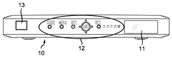
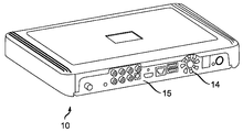
참신한(novel) 리셋 버튼 메커니즘, 광 가이드, 및 열 관리 시스템을 구비한 본 발명에 따른 셋톱 박스(10)는 이제 도 1 내지 도 7을 참조하여 설명될 것이다. 도 1은 전면 측면이 베이 도어(bay door)(11), 전원 버튼(13), 및 표면 도판(surface artwork)을 가지며 다양한 제어 버튼들을 제공하는 전면 패널(12)을 포함하는 셋톱 박스(10)의 전면 측면에 대한 평면도를 도시한다. 도 2는 후면 벽(15)이 다양한 전기 커넥터들의 뱅크(bank), 및 열 관리를 도와줄 통기 배기 송풍기(vented exhaust fan)(14)를 포함하는 셋톱 박스(10)의 후면 사시도를 도시한다.A set
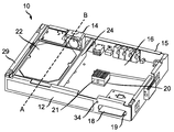
도 3을 참조해보면, 셋톱 박스는 스마트 카드 판독기(17)를 구비한 스마트 카드 구획(section)으로부터, 하드 드라이브(22)를 구비한 하드 드라이브 구획을 분할하는 열 분할 벽(thermal partition wall)(24)을 포함하는 참신한 열 관리 시스템을 구비한다. 도 3은 이러한 셋톱 박스(10) 및 내부 부품들에 대한 내부 사시도를 도시한다. 본 시스템은 제2 인쇄 회로 보드(32)(도시되지 않음) 위의 리셋 버튼(34)을 포함한다. 임의의 열 생성 요소들 및 제2 인쇄 회로 보드(32)를 셋톱 박스(10) 내의 열 생성 요소들 및 메인 인쇄 회로 보드(16)로부터 이격시켜 놓았기 때문에, 제2 인쇄 회로 보드(32)는 열 관리를 돕는다. 도 3a는 특히, 일반화된 전면 패널(12)을 구비한 셋톱 박스(10)를 도시하며, 셋톱 박스의 정상부, 및 스마트 카드 베이 또는 포트(19)에 속한 도어(11)는 내부 특징들을 도시하기 위해 제거된다. 본 예시에서, 배기 송풍기(14)는, 셋톱 박스(10)의 한 측면에 존재할 수 있으며 인쇄 회로 보드(16) 위에 존재할 수 있거나 또는 인쇄 회로 보드(16)에 인접하여 존재할 수 있는 하드 드라이브(22)의 배후에 존재한다. 도 3b는, 인쇄 회로 보드(16) 위의 또는 근처의 열 생성 부품들로부터 열 추출을 돕기 위한 열 패드(20)를 회로 보드가 구비할 수 있는 인쇄 회로 보드(16)를 도시한다. 열 패드(20)는 방열판이 그 위에 배치될 때에 열 추출을 돕는다. 스마트 카드 판독기(17)의 스마트 카드(18)가 일반적으로 상당한 열을 생성하기 때문에, 이러한 열 추출 특징은 중요할 수 있다. 방열판은 방열판 접촉부(heat sink contact)(21) 및 정상부의 넓은 방열판(top broad heat sink)(23)을 포함할 수 있다. 정상부의 넓은 방열판(23)은 셋톱 박스의 메인 집적 회로를 냉각시키기 위한 효율적인 방식임이 입증되었다. 도 3a 및 도 3c는, 냉각 공기 통로와 나란히 뻗어있고 셋톱 박스의 전면 벽과 후면 벽에 수직이며 그 사이에서 확장된 분할 벽(24)을 도시한다. 분할 벽(24)은 회로 보드(16) 위의 넓은 방열판으로부터 하드 드라이브를 분리시킨다. 회로 보드(16)는 후면 벽(15)의 길이에 미칠 수 있다.3, the set top box includes a
도 3c에 도시된 정상부의 넓은 방열판(23)은 포켓, 중앙 하강부, 나치(notch), 리세스(recess), 다층식 하강부(multilevel depression), 또는 평면인 주변부(planar periphery)의 평면으로부터 및/또는 평면인 주변부의 평면으로 확장된 메이서(mesa)와 같은 콘튜어드 중앙 특징부(contoured central feature)(25) 및 일반적으로 평면인 주변부를 구비한 일반적인 콘튜어드 플레이트일 수 있으며, 평면인 주변부는 바람직하게 중앙 하강부를 둘러싼다. 도시된 실시예에서, 평면인 주변부(26)는 중앙 하강 특징부(25)의 측면들(3 또는 4)을 둘러싼다. 중앙 특징부 또는 중앙 하강부(25)는 평면인 주변부로부터 확장된 측면 벽을 구비할 수 있으며, 그 사이에 둔각(obtuse angle)을 형성할 수 있다. 콘튜어드 특징부는 메인 집적 회로와 접촉하도록 설계된 평탄한 바닥부, 및/또는 그 아래에 존재할 수 있는 메인 인쇄 회로 보드(16) 위의 다른 열 생성 부품을 선택적으로 구비할 수 있다.The top
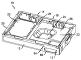
도 4는 공기 흡입구(27)를 통해 공기가 셋톱 박스 안으로 들어가는 셋톱 박스(10)에 대한 열 관리의 추가적인 특징을 도시한다. 도 4는 셋톱 박스의 하드 드라이브 측면에 대한 도 3a의 셋톱 박스(10)의 교차 단면(A-B)이다. 여기서, 하드 드라이브 구획은 셋톱 박스의 후면 벽 위의 배기 송풍기(14)와, 전면 벽 근처의 또는 전면 벽에 인접한 셋톱 박스의 바닥 벽 위의 냉각 공기 흡입구(27) 사이에 냉각 공기 통로(27)를 가진다. 공기 통로(28)는 하드 드라이브(22), 하드 드라이브 케이스, 또는 그 위의 회로 보드, 및 셋톱 박스의 횡 측면 벽(lateral side wall)(29) 및 분할 벽(24)으로 더 한정 또는 제한된다. 냉각 공기 흡입구(27)는 바람직하게도 공기 통로(28)의 길이를 증가시키도록 후면 벽(15)보다 전면 벽에 더 근접하다. 적소의 하드 드라이브를 통해, 본 시스템은 냉각 공기 흡입구로부터, 그리고 셋톱 박스로부터 배기 송풍기를 통해 공기가 흐르게 한다. 요약하자면, 열 관리 시스템은, (1)분할 벽(24)의 스마트 카드 측면 위에서, 열이 정상부의 넓은 방열판(23)으로 전달되고 셋톱 박스의 정상부로 발산되어, 이로써 열이 분배 및 발산되게 하고; (2)분할 벽(24)의 하드 드라이브 측면 위에서, 하드 드라이브(22)로부터의 열이, 하드 드라이브(22)와 접촉하는 부품 벽의 표면 또는 하드 드라이브의 바닥과 접촉하는 공기에 의해 공기 흐름으로 추출되게 하기 위한 것이다. 공기는 배기 송풍기(14)를 통해 거꾸로, 그리고 도 2에 도시된 셋톱 박스(10)의 후면 벽 위의 송풍기 배출구를 통해 밖으로 이동한다.4 shows an additional feature of the thermal management for the set-
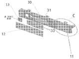
도 5는 셋톱 박스(10)의 전면 단부 어셈블리의 사시도이다. 전면 단부 어셈블리는 전면 패널 회로 보드(32) 위에 존재할 수 있는 스위치들로부터의 광 투과(light transmission)를 위한 개구부를 갖는 광 차단 베젤(light blocking bezel)(31)을 구비한 전면 단부 벽 프레임(30)을 갖는다. 베젤(31)은 베젤의 개구부들을 통해 광을 적절히 분배 또는 확산시키기 위한 광 가이드(33)를 가질 수 있다. 광 소스는 전면 회로 보드(32) 위에 존재할 수 있다. 투명 또는 반투명 전면 패널(12)은 광 가이드(33) 및/또는 베젤(31) 위에 존재할 수 있다. 이 전면 패널(12)은 그 자체에 표면 도판을 가질 수 있다. 스마트 카드 포트 접근 도어(11)는 전면 패널(12)의 한 횡 단부에 존재하며, 스마트 카드 포트 접근 도어(11)의 배후에는 스마트 카드 포트(19) 및 리셋 버튼(34)이 존재한다. 전원 버튼(13)은 도어(11)의 반대편에 있는 전면 패널(12)의 다른 측면에 존재할 수 있다. 전면 패널의 다른 횡 단부의 전원 버튼(13)은 전면 패널(12)에 의해 선택적으로 커버될 수 있다. 셋톱 박스를 작게 유지하기 위한 두께 제한이 존재할 때, 전면 패널 위의 그래픽을 조명하기 위한 수단이 제공된다. 이러한 조명 수단은 전면 패널과 인쇄 회로 보드 사이에 공기가 존재하지 않는 구조가 터치 감지 버튼들을 허용하도록 하여, 이로써 (광학 부품들 및/또는 케이블과 같은) 부분들(parts) 및 갭들(gaps)을 제거할 수 있다.5 is a perspective view of the front end assembly of the set-
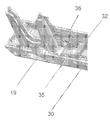
도 6은 도 5의 구획(C)에 도시된 도어(11)의 배후에 존재하는 전면 단부 어셈블리 위의 리셋 버튼 어셈블리(36)의 후면도이다. 스마트 카드 포트(19) 위의 전면 단부 벽 프레임(30) 위에 존재하는 리셋 버튼 어셈블리가 도시된다. 전면 패널 회로 보드(32) 위에 작동 리셋 스위치(35)가 존재한다. 이 스위치(35)는 실제로 작동될 때 셋톱 박스를 리셋한다.Figure 6 is a rear view of the
도 7은 리셋 버튼 어셈블리 또는 메커니즘(36)의 단면도이다. 도 7에서, 도어(11)와 전면 단부 벽 프레임(30)의 배후에 존재하는 메커니즘(36)이 도시된다. 도어(11)는 버튼(34)에 대한 접근을 허용하도록 개방된 채로 스윙(swing)하도록 설계되었다. 메커니즘(36)은 전면 패널 인쇄 회로 보드(32)의 내부 측면 위의 작동 리셋 스위치(35)에 순방향 작동력(39)을 가하는 작동 또는 작동 단부(41)를 구비한다. 전면 패널 인쇄 회로 보드(32)는 셋톱 박스의 전면에 수직으로 배향될 수 있으며, 수평의 메인 인쇄 회로 보드(16)에 수직일 수 있다. 작동 단부(41)는 작동 리셋 스위치(35)와 접촉하는 갈퀴(prong)를 구비할 수 있다. 작동 스위치(35)는 마이크로스위치일 수 있다. 작동 스위치(36)에 가해진 힘(39)은, 작동 단부(41)의 반대편에 있는 메커니즘(36)의 말단 단부(distal end)에서 리셋 버튼(34)에 작용된 후방으로의 작용력(rearward application force) 또는 내부로의 작용력(38)에 반대 방향이다. 메커니즘(36)은 전면 단부 벽 프레임(30)의 풀크럼 포켓(fulcrum pocket)에 놓인(sits in) 풀크럼(37)을 구비한다. 내부로의 작용력(38)은 사용자의 손가락으로부터 버튼 단부(34)에 가해진 힘일 수 있다. 힘(38)은 메커니즘(36)을 풀크럼(37)의 주위에서 도 7에서 시계반대 방향으로 회전시키고, 연속하여 작동력(39)을 작동기 단부(actuator end)(41)에 작용시킨다. 이에 따라, 작동력(39)은 작동 단부(41) 또는 작동 단부(41) 위의 갈퀴를 통해 택트 스위치(tact switch) 또는 작동 리셋 스위치(35)에 작용된다. 메커니즘(36)의 길이 및 셋톱 박스의 전면에 일반적으로 수직일 수 있으며 메커니즘으로부터 셋톱 박스의 전면으로 확장된 스프링 레그(40)가 존재한다. 스프링 레그(40)는 풀크럼(37)의 작동 단부 측면 위에 위치 지정된다. 스프링 레그(40)는 메커니즘이 회전 또는 위치 지정되도록 더 유지할 수 있어서, 버튼 단부(34) 및 작동 단부(41)는 적소에 존재하며, 내부로의 작용력(38)이 작용될 때까지 리셋 스위치는 작동되지 않는다. 풀크럼에 맞닿는 스프링 레그(40)의 측면은, 전면 벽에 수직인 수직 배향된 스프링 레그 벽(42) 위의 작동 단부와 접촉하여, 이러한 작동 단부에 횡력(lateral force)을 작용시킬 수 있다. 이는, 버튼(34)이 가압될 때까지, 작동 리셋 스위치(35)가 작동되는 것을 방지한다.7 is a cross-sectional view of the reset button assembly or
회로 보드들 및/또는 내부 부품들이 일반적으로 열을 생성하기 때문에, 상이한 기능들을 제공하는 본 발명의 실시예에서와 같이 두 개의 보드들을 갖는 것은 셋톱 박스에서 생성된 열의 확산(spreading)과 분배를 향상시킨다. 이는 열을 집중시키는 것(localizing)을 피하고, 열 분산을 위한 보다 많은 기회를 제공한다는 점에 있어서 유리하다. 분할 벽은 공기 통로(27)에 접촉하고 공기 통로(27)를 형성함으로써 열 분산을 더 최적화하는 것을 돕는다.Having two boards, as in embodiments of the present invention that provide different functions, improves spreading and distribution of heat generated in a set-top box, since circuit boards and / or internal components generally generate heat. . This is advantageous in that it avoids localizing the heat and provides more opportunities for heat dissipation. The dividing wall assists in further optimizing heat dissipation by contacting
도면들은 본 개시사항의 개념들을 도시하는 목적을 위한 것이며 반드시 본 개시사항을 도시하기 위한 유일한 가능한 구성이 아니라는 것이 이해될 것이다. 예를 들어, 본 예시들이 셋톱 박스와 스마트 카드들에 관하여 언급될지라도, 본 발명은 하드 드라이브들을 구비한 다른 전자 디바이스들에 적용될 수 있으며, 이들 다른 디바이스들은 스마트 카드들과는 다른 유형의 정보 카드들을 포함할 수 있다.It is to be understood that the drawings are for purposes of illustrating the concepts of the present disclosure and are not necessarily the only possible configurations for illustrating the present disclosure. For example, although these examples are mentioned with respect to set-top boxes and smart cards, the present invention may be applied to other electronic devices with hard drives, these other devices include different types of information cards than smart cards can do.
10 : 셋톱 박스 11 : 베이 도어
12 : 전면 패널 13 : 전원 버튼
14 : 배기 송풍기 15 : 후면 벽
16 : 인쇄 회로 보드 17 : 스마트 카드 판독기
18 : 스마트 카드 20 : 열 패드
21 : 방열판 접촉부 22 : 하드 드라이브
29 : 횡 측면 벽 34 : 리셋 버튼10: Set-top box 11: bay door
12: Front panel 13: Power button
14: exhaust blower 15: rear wall
16: printed circuit board 17: smart card reader
18: Smart Card 20: Thermal Pad
21: heat sink contact portion 22: hard drive
29: lateral side wall 34: reset button
Claims (15)
전면 벽(front wall);
전면 벽의 내부 표면 위의 제1 인쇄 회로 보드;
전면 벽의 반대편에 있는 제1 인쇄 회로 보드의 측면 위에 있는 제1 인쇄 회로 보드 위의 작동 리셋 스위치(actuation reset switch); 및
작동 단부와 리셋 버튼 단부 사이의 풀크럼(fulcrum)을 구비한 리셋 버튼 어셈블리;를 포함하며, 리셋 버튼 단부는 리셋 버튼을 포함하고, 작동 단부는 작동 갈퀴(actuation prong)를 포함하고, 작동 갈퀴는 작동 리셋 스위치에 맞닿고, 리셋 버튼은 작동 갈퀴와 동일한 방향으로 맞닿는, 전자 디바이스.As an electronic device,
A front wall;
A first printed circuit board on the inner surface of the front wall;
An actuation reset switch on the first printed circuit board on the side of the first printed circuit board opposite the front wall; And
A reset button assembly having a fulcrum between the operative end and the reset button end, the reset button end including a reset button, the operative end including an actuation prong, And the reset button abuts in the same direction as the actuating rake.
리셋 버튼 어셈블리는 내부로의 작용력(inward force)이 리셋 버튼에 작용될 때 전자 디바이스를 리셋하도록 구성되고, 작동 갈퀴가 리셋을 개시하기 위해 순방향 작동력(forward activation force)을 작동 리셋 스위치에 가하도록, 내부로의 작용력은 리셋 버튼 어셈블리가 풀크럼의 주위에서 회전하게 하며, 내부로의 작용력 및 순방향 작동력은 반대 방향인, 전자 디바이스.The method according to claim 1,
The reset button assembly is configured to reset the electronic device when an inward force into the reset button is applied to the reset button assembly and cause the operating lever to apply a forward activation force to the actuated reset switch to initiate a reset, The force acting on the interior causes the reset button assembly to rotate around the pull crumb, and the force acting on the inside and the force acting on the forward direction are opposite.
내부 표면에 맞닿고 내부 표면에 수직인 스프링 레그(spring leg)를 포함하고, 스프링 레그는 풀크럼과 작동 갈퀴 사이에 존재하고, 스프링 레그는, 작동 갈퀴가 작동 리셋 스위치에 인접하고 내부로의 작용력이 작용될 때에 작동 리셋 스위치를 작동시키도록 위치 지정되도록, 리셋 버튼 어셈블리를 적소에 고정하는, 전자 디바이스. 3. The method of claim 2,
Wherein the spring leg is located between the pull crumb and the actuating rake and the spring leg is configured such that the actuating rake is adjacent to the actuating reset switch and has an internal force Wherein the reset button assembly is positioned to actuate an actuation reset switch upon actuation of the reset button assembly.
수평이며, 제1 인쇄 회로 보드에 수직인 제2 인쇄 회로 보드; 및
제2 인쇄 회로 보드 위의 스마트 카드 판독기;를 포함하는, 전자 디바이스.The method of claim 3,
A second printed circuit board that is horizontal and perpendicular to the first printed circuit board; And
And a smart card reader on the second printed circuit board.
중앙 하강부(central depression portion)를 둘러싼 평면 주변부(planar peripheral portion)를 구비한 정상부 방열판(top heat sink)을 포함하고, 중앙 하강부는 제2 인쇄 회로 보드 위에 있는 열 생성 부품(heat generating component)에 접촉하는, 전자 디바이스.5. The method of claim 4,
And a top heat sink having a planar peripheral portion surrounding a central depression portion, wherein the central downward portion includes a heat generating component on a second printed circuit board ≪ / RTI >
수평이며, 제1 인쇄 회로 보드에 수직인 제2 인쇄 회로 보드; 및
제2 인쇄 회로 보드 위의 또는 제2 인쇄 회로 보드에 인접한 하드 드라이브;를 포함하는, 전자 디바이스.The method of claim 3,
A second printed circuit board that is horizontal and perpendicular to the first printed circuit board; And
And a hard drive on or adjacent to the second printed circuit board.
전자 디바이스의 바닥 측면 위의, 그리고 하드 드라이브 아래의 냉각 공기 흡입구(cooling air intake vent);
전자 디바이스의 후면 벽(rear wall) 위의 배기 송풍기(exhaust fan); 및
적어도 하드 드라이브의 부분 아래에 위치 지정되고, 냉각 공기 흡입구와 배기 송풍기 사이에 존재하는 냉각 공기 통로(cooling air channel);를 포함하는, 전자 디바이스.The method according to claim 6,
A cooling air intake vent on the bottom side of the electronic device and below the hard drive;
An exhaust fan on the rear wall of the electronic device; And
And a cooling air channel located at least below the portion of the hard drive and present between the cooling air inlet and the exhaust blower.
제2 인쇄 회로 보드 위의, 그리고 제2 인쇄 회로 보드에 인접한 하드 드라이브;
전자 디바이스의 바닥 측면 위의, 그리고 하드 드라이브 아래의 냉각 공기 흡입구;
전자 디바이스의 후면 벽 위의 배기 송풍기; 및
적어도 하드 드라이브의 부분 아래에 위치 지정되고, 냉각 공기 흡입구와 배기 송풍기 사이에 존재하는 냉각 공기 통로;를 포함하는, 전자 디바이스.6. The method of claim 5,
A hard drive on the second printed circuit board and adjacent to the second printed circuit board;
Cooling air intake above the bottom side of the electronic device and below the hard drive;
An exhaust blower on the rear wall of the electronic device; And
And a cooling air passage positioned below at least a portion of the hard drive and being present between the cooling air inlet and the exhaust blower.
분할 벽(partition wall)을 포함하고, 하드 드라이브와 냉각 공기 통로는 분할 벽의 한 측면에 존재하고, 스마트 카드 판독기와 정상부 방열판은 분할 벽의 반대편에 존재하는, 전자 디바이스.9. The method of claim 8,
Wherein the hard drive and cooling air passages are on one side of the dividing wall and the smart card reader and the top heat sink are on opposite sides of the dividing wall.
전자 디바이스는 셋톱 박스인, 전자 디바이스.The method according to claim 1,
The electronic device is a set-top box.
제2 인쇄 회로 보드; 및
제2 인쇄 회로 보드 위의 정보 카드 판독기;를 포함하는, 전자 디바이스.The method of claim 3,
A second printed circuit board; And
And an information card reader on the second printed circuit board.
중앙 하강부를 둘러싼 평면 주변부를 구비한 정상부 방열판을 포함하고, 중앙 하강부는 제2 인쇄 회로 보드 위의 열 생성 부품에 접촉하는, 전자 디바이스.12. The method of claim 11,
And a top portion heat sink having a planar periphery surrounding the central down portion, the central down portion contacting the heat generating component on the second printed circuit board.
전자 디바이스의 바닥 측면 위의, 그리고 하드 드라이브 아래의 냉각 공기 흡입구;
전자 디바이스의 후면 벽 위의 배기 송풍기; 및
적어도 하드 드라이브의 부분 아래에 위치 지정되고, 냉각 공기 흡입구와 배기 송풍기의 사이에 존재하는 냉각 공기 통로;를 포함하는, 전자 디바이스.13. The method of claim 12,
Cooling air intake above the bottom side of the electronic device and below the hard drive;
An exhaust blower on the rear wall of the electronic device; And
And a cooling air passage positioned below at least a portion of the hard drive and being present between the cooling air inlet and the exhaust blower.
수평이며, 제1 인쇄 회로 보드에 수직인 제2 인쇄 회로 보드;
제2 인쇄 회로 보드 위의, 또는 제2 인쇄 회로 보드에 인접한 하드 드라이브;
전자 디바이스의 바닥 측면 위의, 그리고 하드 드라이브 아래의 냉각 공기 흡입구;
전자 디바이스의 후면 벽 위의 배기 송풍기;
적어도 하드 드라이브의 부분 아래에 위치 지정되고, 냉각 공기 흡입구와 배기 송풍기의 사이에 존재하는 냉각 공기 통로; 및
분할 벽;을 포함하며, 하드 드라이브와 냉각 공기 통로는 분할 벽의 한 측면에 존재하고, 스마트 카드 판독기와 정상부 방열판은 분할 벽의 반대편에 존재하는, 전자 디바이스.The method of claim 3,
A second printed circuit board that is horizontal and perpendicular to the first printed circuit board;
A hard drive adjacent to or on the second printed circuit board;
Cooling air intake above the bottom side of the electronic device and below the hard drive;
An exhaust blower on the rear wall of the electronic device;
A cooling air passage positioned at least below the portion of the hard drive and present between the cooling air inlet and the exhaust blower; And
Wherein the hard drive and cooling air passages are on one side of the dividing wall and the smart card reader and the top heat sink are on opposite sides of the dividing wall.
분할 벽을 포함하고, 하드 드라이브와 냉각 공기 통로는 분할 벽의 한 측면에 존재하고, 스마트 카드 판독기와 정상부 방열판은 분할 벽의 반대편에 존재하는, 전자 디바이스.14. The method of claim 13,
Wherein the hard drive and cooling air passages are on one side of the dividing wall and the smart card reader and the top heat sink are on opposite sides of the dividing wall.
Applications Claiming Priority (3)
| Application Number | Priority Date | Filing Date | Title |
|---|---|---|---|
| US201161464778P | 2011-03-09 | 2011-03-09 | |
| US61/464,778 | 2011-03-09 | ||
| PCT/US2012/027995 WO2012122226A2 (en) | 2011-03-09 | 2012-03-07 | Set top box having reset button and light guide |
Publications (1)
| Publication Number | Publication Date |
|---|---|
| KR20140062423A true KR20140062423A (en) | 2014-05-23 |
Family
ID=46798759
Family Applications (1)
| Application Number | Title | Priority Date | Filing Date |
|---|---|---|---|
| KR1020137023847A KR20140062423A (en) | 2011-03-09 | 2012-03-07 | Set top box having reset button and light guide |
Country Status (7)
| Country | Link |
|---|---|
| US (1) | US9363547B2 (en) |
| EP (1) | EP2684374B1 (en) |
| JP (1) | JP5981462B2 (en) |
| KR (1) | KR20140062423A (en) |
| CN (1) | CN104011818A (en) |
| BR (1) | BR112013022659A2 (en) |
| WO (1) | WO2012122226A2 (en) |
Families Citing this family (2)
| Publication number | Priority date | Publication date | Assignee | Title |
|---|---|---|---|---|
| WO2015148259A1 (en) * | 2014-03-25 | 2015-10-01 | Thomson Licensing | Overlay application fixture |
| JP2017532679A (en) | 2014-09-25 | 2017-11-02 | トムソン ライセンシングThomson Licensing | Electronic devices |
Family Cites Families (43)
| Publication number | Priority date | Publication date | Assignee | Title |
|---|---|---|---|---|
| GB1076373A (en) | 1964-03-17 | 1967-07-19 | Electrical Prot Company Propri | Improvements relating to polarised electromagnetic relays |
| DE3034540C2 (en) | 1980-09-12 | 1984-06-07 | Siemens AG, 1000 Berlin und 8000 München | Push button switch |
| US4388508A (en) | 1981-09-25 | 1983-06-14 | Wilson Dallas W | Switch actuating mechanism |
| JPS6183227U (en) * | 1984-11-07 | 1986-06-02 | ||
| JPS63108138U (en) * | 1986-12-31 | 1988-07-12 | ||
| US5517165A (en) | 1991-07-22 | 1996-05-14 | Pdl Holdings Limited | Switch mechanism |
| FR2709713B1 (en) | 1993-09-07 | 1995-11-10 | Sagem | On-board equipment with light pipe. |
| JPH09161607A (en) * | 1995-12-14 | 1997-06-20 | Matsushita Electric Ind Co Ltd | Switch operating button |
| JP3776169B2 (en) * | 1996-06-13 | 2006-05-17 | 任天堂株式会社 | Heat dissipation structure of electronic equipment |
| US6231444B1 (en) | 1996-10-11 | 2001-05-15 | Sony Computer Entertainment Inc. | Operating device for game machine |
| US6141213A (en) | 1997-06-24 | 2000-10-31 | Sun Microsystems, Inc. | Computer with high airflow and low acoustic noise |
| JP2000173393A (en) * | 1998-12-04 | 2000-06-23 | Omron Corp | Switch structure and control equipment using the same |
| EP1006767B1 (en) | 1998-11-30 | 2006-06-07 | Omron Corporation | Electronic component comprising a control unit with a battery holder including a battery reverse insertion prevention means |
| US6373697B1 (en) | 1999-06-28 | 2002-04-16 | Sun Microsystems, Inc. | Computer system housing and configuration |
| US6667447B2 (en) * | 2002-01-07 | 2003-12-23 | Hon Hai Precision Ind. Co., Ltd. | Button device in computer bezel |
| JP2003257279A (en) * | 2002-03-01 | 2003-09-12 | Sharp Corp | Key device |
| US20030177506A1 (en) * | 2002-03-15 | 2003-09-18 | Kinpo Electronics, Inc. | Set top box |
| AU2003208542A1 (en) | 2002-03-22 | 2003-10-08 | Koninklijke Philips Electronics N.V. | Modular set top box_____________________________________________ |
| JP2003288131A (en) * | 2002-03-27 | 2003-10-10 | Nec Corp | System and method for deciding and controlling automatic restarting of device equipped with real-time os |
| EP1382973A1 (en) * | 2002-07-19 | 2004-01-21 | Thomson Licensing S.A. | Method and test adapter for testing an appliance having a smart card reader |
| JP2004288440A (en) * | 2003-03-20 | 2004-10-14 | Pioneer Electronic Corp | Switch for electronic equipment, electronic equipment, and manufacturing device for electronic equipment |
| JP4039316B2 (en) * | 2003-06-09 | 2008-01-30 | 株式会社明電舎 | Electronic equipment cooling structure |
| JP2005182857A (en) * | 2003-12-16 | 2005-07-07 | Matsushita Electric Ind Co Ltd | Tape storage |
| KR100597008B1 (en) * | 2004-03-09 | 2006-07-06 | 삼성전자주식회사 | Operating key for electronic device |
| TWI256192B (en) * | 2004-04-15 | 2006-06-01 | Acbel Polytech Inc | Power adapter with heat sink device |
| US7323986B2 (en) * | 2004-09-03 | 2008-01-29 | Gore Enterprise Holdings, Inc. | Reusable tamper respondent enclosure |
| US7158380B2 (en) * | 2005-03-25 | 2007-01-02 | Scientific-Atlanta, Inc. | Heatsink for digital video recorder |
| CN2859657Y (en) * | 2005-09-09 | 2007-01-17 | 盛趣信息技术(上海)有限公司 | Interactive recreation terminal |
| EP1788853A1 (en) * | 2005-11-21 | 2007-05-23 | Thomson Licensing | Electronic device comprising a metal housing and a cosmetic envelope |
| US7558034B2 (en) | 2006-05-18 | 2009-07-07 | Leviton Manufacturing Company, Inc. | Bi-directional ground fault circuit interrupter |
| CN101449442A (en) | 2006-05-18 | 2009-06-03 | 立维腾制造有限公司 | Bi-directional ground fault circuit interrupter |
| JP4167700B2 (en) * | 2006-05-31 | 2008-10-15 | 株式会社東芝 | Electronics |
| CN1874669A (en) * | 2006-06-21 | 2006-12-06 | 南京Lg同创彩色显示系统有限责任公司 | Cooling channel for flat panel display |
| US7381919B1 (en) | 2007-02-22 | 2008-06-03 | Inventec Corporation | Lever button of electronic product |
| JP4857252B2 (en) * | 2007-12-07 | 2012-01-18 | 株式会社日立製作所 | Electronics |
| US8773827B2 (en) * | 2008-02-19 | 2014-07-08 | Simply Automated Incorporated | Intelligent circuit breaker apparatus and methods |
| JP4473923B2 (en) * | 2008-10-22 | 2010-06-02 | 株式会社東芝 | Electronics |
| JP5095691B2 (en) * | 2008-10-27 | 2012-12-12 | 富士電機機器制御株式会社 | Push-button switch |
| TWM351435U (en) | 2008-10-27 | 2009-02-21 | Inventec Appliances Corp | Reset button structure |
| CN201352820Y (en) | 2009-02-10 | 2009-11-25 | 深圳创维数字技术股份有限公司 | Set-top box case |
| US8902588B2 (en) * | 2009-12-09 | 2014-12-02 | Thomson Licensing | Set-top box having microperforations |
| JP5981463B2 (en) * | 2011-03-09 | 2016-08-31 | トムソン ライセンシングThomson Licensing | Electronic equipment |
| US20140175314A1 (en) | 2011-05-06 | 2014-06-26 | IV Valve ApS | Strain relieving valve assembly with flow blocking |
-
2012
- 2012-03-07 BR BR112013022659A patent/BR112013022659A2/en active Search and Examination
- 2012-03-07 KR KR1020137023847A patent/KR20140062423A/en not_active Application Discontinuation
- 2012-03-07 CN CN201280011535.8A patent/CN104011818A/en active Pending
- 2012-03-07 US US14/002,197 patent/US9363547B2/en active Active
- 2012-03-07 WO PCT/US2012/027995 patent/WO2012122226A2/en active Application Filing
- 2012-03-07 EP EP12754929.3A patent/EP2684374B1/en not_active Not-in-force
- 2012-03-07 JP JP2013557817A patent/JP5981462B2/en not_active Expired - Fee Related
Also Published As
| Publication number | Publication date |
|---|---|
| JP5981462B2 (en) | 2016-08-31 |
| EP2684374A4 (en) | 2015-11-18 |
| BR112013022659A2 (en) | 2016-12-06 |
| EP2684374A2 (en) | 2014-01-15 |
| EP2684374B1 (en) | 2018-08-01 |
| US9363547B2 (en) | 2016-06-07 |
| US20130340025A1 (en) | 2013-12-19 |
| CN104011818A (en) | 2014-08-27 |
| JP2014515155A (en) | 2014-06-26 |
| WO2012122226A2 (en) | 2012-09-13 |
| WO2012122226A3 (en) | 2014-04-17 |
| WO2012122226A8 (en) | 2013-09-26 |
Similar Documents
| Publication | Publication Date | Title |
|---|---|---|
| US10365699B2 (en) | Computer case cooling structure | |
| KR101266874B1 (en) | Image projecting apparatus | |
| US6353536B1 (en) | Electronic equipment system and extension device for expanding the functions of electronic equipment | |
| US7733646B2 (en) | Frontal structure of information processing apparatus | |
| US7715193B1 (en) | Electronic device and air regulation apparatus thereof | |
| US7911781B2 (en) | Electronic device | |
| JP6088078B2 (en) | Electronic device enclosure with improved ventilation for dissipating heat | |
| US20090268394A1 (en) | Heat-radiating microcomputer case | |
| KR20140062423A (en) | Set top box having reset button and light guide | |
| JP2013179003A (en) | Lighting fixture | |
| KR20160053948A (en) | Control console for a numerically controlled machine tool | |
| US20100130120A1 (en) | Air conducting device | |
| JP6868716B1 (en) | Electronics | |
| TWI652002B (en) | Light guide heat dissipation module and electronic device | |
| CN113641215A (en) | Vertical modular mini-computer that piles up | |
| CN217363590U (en) | Good heat dissipation's terminal | |
| JP2013222275A (en) | Electronic device | |
| US11808932B2 (en) | Microscope stand and module and housing therefor | |
| JP3110951U (en) | Internally installed cooling device for electronic equipment, and electronic equipment in which the cooling device is installed | |
| JP4190875B2 (en) | Push button switch for vending machine | |
| JPH10307647A (en) | Computer device | |
| JP2005310544A (en) | Installation type information processing device | |
| JP6241315B2 (en) | Electronic device and electronic communication device | |
| JP2005166732A (en) | Electronic apparatus system | |
| JPH05343870A (en) | Electronic equipment having heat dissipation mechanism |
Legal Events
| Date | Code | Title | Description |
|---|---|---|---|
| A201 | Request for examination | ||
| WITB | Written withdrawal of application |