KR20140056816A - Abutment holder for implanting - Google Patents
Abutment holder for implanting Download PDFInfo
- Publication number
- KR20140056816A KR20140056816A KR1020120122687A KR20120122687A KR20140056816A KR 20140056816 A KR20140056816 A KR 20140056816A KR 1020120122687 A KR1020120122687 A KR 1020120122687A KR 20120122687 A KR20120122687 A KR 20120122687A KR 20140056816 A KR20140056816 A KR 20140056816A
- Authority
- KR
- South Korea
- Prior art keywords
- abutment
- protruding
- concave
- convex portion
- groove
- Prior art date
Links
Images
Classifications
-
- A—HUMAN NECESSITIES
- A61—MEDICAL OR VETERINARY SCIENCE; HYGIENE
- A61C—DENTISTRY; APPARATUS OR METHODS FOR ORAL OR DENTAL HYGIENE
- A61C8/00—Means to be fixed to the jaw-bone for consolidating natural teeth or for fixing dental prostheses thereon; Dental implants; Implanting tools
- A61C8/0089—Implanting tools or instruments
-
- A—HUMAN NECESSITIES
- A61—MEDICAL OR VETERINARY SCIENCE; HYGIENE
- A61C—DENTISTRY; APPARATUS OR METHODS FOR ORAL OR DENTAL HYGIENE
- A61C3/00—Dental tools or instruments
-
- A—HUMAN NECESSITIES
- A61—MEDICAL OR VETERINARY SCIENCE; HYGIENE
- A61C—DENTISTRY; APPARATUS OR METHODS FOR ORAL OR DENTAL HYGIENE
- A61C8/00—Means to be fixed to the jaw-bone for consolidating natural teeth or for fixing dental prostheses thereon; Dental implants; Implanting tools
- A61C8/0048—Connecting the upper structure to the implant, e.g. bridging bars
- A61C8/005—Connecting devices for joining an upper structure with an implant member, e.g. spacers
- A61C8/0068—Connecting devices for joining an upper structure with an implant member, e.g. spacers with an additional screw
Landscapes
- Health & Medical Sciences (AREA)
- Oral & Maxillofacial Surgery (AREA)
- Dentistry (AREA)
- Epidemiology (AREA)
- Life Sciences & Earth Sciences (AREA)
- Animal Behavior & Ethology (AREA)
- General Health & Medical Sciences (AREA)
- Public Health (AREA)
- Veterinary Medicine (AREA)
- Orthopedic Medicine & Surgery (AREA)
- Dental Prosthetics (AREA)
Abstract
Description
본 발명은 임플란트 시술 시에 사용되는 어버트먼트 홀더에 관한 것이다.
The present invention relates to an abutment holder used in an implant procedure.
일반적으로, 임플란트(IMPLANT)는 인공 치아 또는 제3의 치아라고도 한다. 치아의 결손이 있는 부위나 치아를 뽑은 자리의 턱뼈에 골 이식, 골 신장술 등의 부가적인 수술을 통하여, 충분히 감쌀 수 있도록 부피를 늘린 턱뼈에 생체 적합적인 임플란트 본체를 심어서 자연치의 기능을 회복시켜주는 치과 치료 술식이다. Generally, an implant (IMPLANT) is also called an artificial tooth or a third tooth. By implanting a biocompatible implant body on the jawbone that has been enlarged so that it can be adequately wrapped through additional operations such as bone grafting and osseointegration on the site of the tooth defect or the jaw bone of the site where the tooth is extracted, It is a dental treatment technique.
정상적인 기능이 유지되고 있는 턱뼈와 식립된 임플란트 본체 표면과의 형태적, 생리적, 직접적 결합인 골유착(osseointegration)이 이루어진 후 임플란트 주위 턱뼈의 골 개조의 과정을 거치게 된다. 임플란트는 여러 종류가 있으나 근래에는 나사 형태의 골 내 임플란트가 주로 사용된다.After the osseointegration, which is a morphological, physiological and direct coupling between the jawbone and the surface of the implanted body, which is normally maintained, is performed, the bone is subjected to a bone remodeling process of the peri-implant jaw. There are many types of implants, but screw implants have recently been used.
이러한 임플란트 시술에 있어서는, 치조골에 박히는 픽스쳐와, 픽스쳐에 결합되는 어버트먼트 등이 요구된다. 이때, 어버트먼트를 집어서 이동시키는 것, 그리고 어버트먼트를 픽스쳐에 결합하는 것은, 어버트먼트의 크기가 작아서 쉽지 않은 작업이 된다.In such an implant procedure, a fixture to be caught in the alveolar bone, an abutment to be coupled to the fixture, and the like are required. At this time, picking up and moving the abutment, and combining the abutment with the fixture, is not easy because the size of the abutment is small.
본 발명의 목적은, 어버트먼트를 고정하여 간단히 잡고서 어버트먼트를 픽스쳐에 고정할 수 있게 하는, 임플란트 시술용 어버트먼트 홀더를 제공하는 것이다.
SUMMARY OF THE INVENTION It is an object of the present invention to provide an abutment holder for implant treatment which can fix an abutment and hold it simply to fix the abutment to the fixture.
상기한 과제를 실현하기 위한 본 발명의 일 실시예와 관련된 임플란트 시술용 어버트먼트 홀더는, 일 단부에 어버트먼트를 수용 가능하게 형성되는 수용부를 구비하고, 길이 방향을 따라 연장 형성되는 몸체; 상기 수용부에 형성되어, 상기 어버트먼트에 탈착 가능하게 결합되도록 형성되는 체결부; 및 상기 몸체의 타 단부에서 상기 일 단부를 향해 연장 형성되어, 상기 수용부와 연통되도록 형성되는 연통 채널을 포함할 수 있다.According to an embodiment of the present invention, there is provided an abutment holder for implant treatment, comprising: a body having a receiving portion formed at one end thereof to receive an abutment and extending along a longitudinal direction; A coupling part formed in the receiving part and detachably coupled to the abutment; And a communication channel formed to extend from the other end of the body toward the one end so as to communicate with the receiving portion.
여기서, 상기 체결부는 상기 수용부의 내면에서 돌출 형성되는 돌기부를 포함할 수 있다.Here, the fastening portion may include a protrusion protruding from the inner surface of the receiving portion.
여기서, 상기 연통 채널은 상기 수용부의 상기 일 단부에 가장 인접한 부분 보다 작은 내경을 갖도록 형성될 수 있다.Here, the communicating channel may be formed to have a smaller inner diameter than a portion closest to the one end of the receiving portion.
여기서, 상기 몸체의 타 단부에 인접한 영역에 형성되며, 상기 몸체의 상기 길이 방향을 따라 등 간격으로 형성되는 제1 요철부를 더 포함할 수 있다.The apparatus may further include a first concavo-convex portion formed in an area adjacent to the other end of the body and formed at regular intervals along the longitudinal direction of the body.
여기서, 상기 제1 요철부는, 상기 몸체의 둘레 방향을 따라 연장하도록 돌출 형성되는 복수의 돌출 링; 및 상기 복수의 돌출 링 중 인접한 돌출링들 사이에 리세스되어 형성되며, 상기 돌출 링과 동일한 폭을 가지는 그루브를 포함할 수 있다.Here, the first concave-convex portion may include a plurality of protruding rings protruding to extend along the circumferential direction of the body; And a groove formed by recessing between adjacent ones of the plurality of the projecting rings, the groove having the same width as the projecting ring.
여기서, 상기 복수의 돌출 링은 각각은 부분적으로 커팅된 커팅면을 포함할 수 있다.Here, the plurality of protruding rings may each include a partially cut cutting surface.
여기서, 상기 복수의 돌출 링 중 상기 몸체의 타 단부에 가장 인접한 돌출 링은 다른 돌출 링 보다 작은 단면적을 가지도록 형성될 수 있다.The protruding ring closest to the other end of the body among the plurality of protruding rings may have a smaller cross sectional area than the other protruding rings.
여기서, 상기 몸체의 일 단부 측에 인접한 영역에 형성되며, 교대로 배열되는 원형의 돌출 링과 원형의 그루브를 구비하는 제2 요철부를 더 포함할 수 있다.The apparatus may further include a second concave and convex portion formed in a region adjacent to the one end of the body and having a circular protruding ring and a circular groove alternately arranged.
여기서, 상기 제2 요철부의 그루브의 폭은 상기 제1 요철부의 그루브의 폭 보다 작게 형성될 수 있다.
Here, the width of the groove of the second concavo-convex portion may be smaller than the width of the groove of the first concavo-convex portion.
상기와 같이 구성되는 본 발명에 관련된 임플란트 시술용 어버트먼트 홀더에 의하면, 어버트먼트를 고정하여 간단히 잡고서 어버트먼트를 픽스쳐에 고정할 수 있게 된다.
According to the abutment holder for implant treatment according to the present invention configured as described above, the abutment can be fixed and easily gripped, and the abutment can be fixed to the fixture.
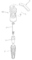
도 1은 본 발명의 일 실시예에 따른 임플란트 시술용 어버트먼트 홀더(100)의 사용 환경을 보인 개념도이다.
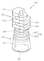
도 2는 도 1의 임플란트 시술용 어버트먼트 홀더(100)의 구조를 보인 사시도이다.FIG. 1 is a conceptual view showing a use environment of an
2 is a perspective view showing a structure of an
이하, 본 발명의 바람직한 실시예에 따른 임플란트 시술용 어버트먼트 홀더에 대하여 첨부한 도면을 참조하여 상세히 설명한다. 본 명세서에서는 서로 다른 실시예라도 동일·유사한 구성에 대해서는 동일·유사한 참조번호를 부여하고, 그 설명은 처음 설명으로 갈음한다.Hereinafter, an abutment holder for implant treatment according to a preferred embodiment of the present invention will be described in detail with reference to the accompanying drawings. In the present specification, the same or similar reference numerals are given to different embodiments in the same or similar configurations.
도 1은 본 발명의 일 실시예에 따른 임플란트 시술용 어버트먼트 홀더(100)의 사용 환경을 보인 개념도이다.FIG. 1 is a conceptual view showing a use environment of an
본 도면을 참조하면, 임플란트 시술용 어버트먼트 홀더(100)는, 임플란트 시술 시에 픽스쳐(F)에 결합되는 어버트먼트(A)에 체결되도록 형성된다. 다시 말해서, 홀더(100)의 일 단부 측 부분[수용부(111, 도 2)]에는 어버트먼트(A)가 수용된다.Referring to the drawings, an
이때, 어버트먼트(A)와 픽스쳐(F)의 결합을 위해서, 나사(S)가 사용될 수 있다. 나사(S)로 어버트먼트(A)를 픽스쳐(F)에 체결하기 위해서는, 툴(T)을 가지는 핸드피스(H)가 이용될 수 있다. At this time, in order to join the abutment A and the fixture F, a screw S may be used. In order to fasten the abutment A to the fixture F with the screw S, a handpiece H having a tool T can be used.
여기서, 어버트먼트(A)가 홀더(100)에 수용된 상태에서, 툴(T)은 홀더(100)의 내부의 공동 부분[(연통 채널(150) 및 수용부(111)]을 통해 나사(S)에 접근될 수 있다. 물론, 나사(S)는 어버트먼트(A)의 중공 부분 및 픽스쳐(F)의 중공 부분을 체결하도록 형성된다.Here, with the abutment A accommodated in the
이러한 홀더(100)에 대해 도 2를 참조하여 구체적으로 설명한다.Such a
도 2는 도 1의 임플란트 시술용 어버트먼트 홀더(100)의 구조를 보인 사시도이다.2 is a perspective view showing a structure of an
본 도면을 참조하면, 홀더(100)는, 몸체(110)와, 체결부(130)와, 연통 채널(150)과, 제1 요철부(170)와, 제2 요철부(190)를 포함할 수 있다. The
몸체(110)는 길이 방향으로 연장 형성되며, 대체로 원형의 단면을 가지는 파이프 형태를 가질 수 있다. 몸체(110)의 일 단부에 어버트먼트(A, 도 1)를 수용하는 공간인 수용부(111)가 형성된다.The
체결부(130)는 수용부(111)에 형성되어, 어버트먼트(A)가 탈착 결합되게 한다. 체결부(130)는 구체적으로, 수용부(111)의 내주면을 따라 링 형태로 연장 형성되는 돌기부를 포함할 수 있다. The
연통 채널(150)은 몸체(110)의 타 단부에서 상기 일 단부를 향해 연장 형성되는 빈 공간이다. 연통 채널(150)은 상기 일 단부에서 수용부(111)와 연통되도록 형성된다. 연통 채널(150)의 내경은 핸드피스(H)의 툴(T, 도 1)이 삽입될 정도만 되면 되므로, 수용부(111) 보다는 작은 내경을 가질 수 있다. The
제1 요철부(170)는 몸체(110)의 상기 타 단부에 인접한 영역에 형성된다. 제1 요철부(170)는 몸체(110)의 길이 방향을 따라 등 간격으로 형성된다. 구체적으로, 제1 요철부(170)는 돌출 링(171)과, 그루브(173)를 포함할 수 있다. 돌출 링(171)은 복수 개로 형성되고, 그루브(173) 역시 복수 개로 형성될 수 있다. 이 경우, 인접한 돌출 링(171) 사이에는 그루브(173)가 배치되고, 역으로 인접한 그루브(173) 사이에는 돌출 링(171)이 배치된다. The first concavo-
돌출 링(171)은 몸체(110)의 둘레 방향을 따라 연장 형성된다. 본 실시예에서, 돌출 링(171)은 대체로 링 형상을 가진다. 돌출 링(171)의 일 면은 커팅되어 커팅면(171a)을 형성할 수 있다. 돌출 링(171) 중에서 몸체(110)의 상기 타 단부에 가장 인접한 단부 돌출 링(172)은 다른 돌출 링(171)에 비하여 작은 단면적을 가질 수 있다. 그루브(173)는 돌출 링(171)에 비해 리세스된(recessed) 구성이다. 이때, 그루브(173)의 폭은 돌출 링(171)의 폭[도면 상, 높이]과 동일한 것일 수 있다. The protruding
제2 요철부(190)는 제1 요철부(170)와 유사하게 돌출 링(191)과 그루브(193)가 교대로 배열된 형태이다. 이때, 돌출 링(191)과 그루브(193)는 완전한 원형을 이루도록 형성될 수 있다. 또한, 제2 요철부(190)의 그루브(193)의 폭[도면 상, 높이]은 제1 요철부(170)의 그루부(173)의 폭 보다 작은 것일 수 있다. The second concave-
이러한 구성에 의한 홀더(100)의 사용 예에 대해 추가로 설명한다.An example of using the
먼저, 홀더(100)는, 앞서 설명한 바대로, 그의 수용부(111)를 통해 어버트먼트(A)를 수용하게 된다. 이러한 홀더(100)를 손에 잡음으로써, 손이나 핀셋을 이용하는 경우보다 편리하게 어버트먼트(A)를 잡을 수 있게 된다. 이때, 체결부(130)는 홀더(100)가 어버트먼트(A)와 간단히 체결되고, 또한 그에서 분리될 수 있게 한다. First, the
다음으로, 연통 채널(150) 및 수용부(111)과 하나로 연통되는 중공 부분을 형성함에 의해, 핸드피스(H)의 툴(T, 도 1)을 상기 중공 부분으로 집어 넣어서, 수용부(111)에 위치하는 나사(S, 도 1)를 조작할 수 있다. 이러한 나사(S)에 의해, 어버트먼트(A)는 픽스쳐(F)에 결합될 수 있다.Next, a hollow portion communicating with the
또한, 제1 요철부(170)가 등 간격으로 형성됨에 의해, 하나의 돌출 링(171) 또는 하나의 그루브(173)의 높이를 직관적으로 파악할 수 있다. 그에 의해, 환자의 상태에 따라서, 요구되는 길이로 몸체(110)의 일 부분을 삭제할 수 있다. 이때, 제1 요철부(170)의 돌출 링(171) 또는 그루브(173)가 삭제될 정도에 대한 기준을 제시하는 것이다.In addition, since the first concavo-
또한, 어버트먼트(A)에 홀더(100)를 결합시킨 후에 잇몸을 스캔하여 임플란트의 식립 방향을 추적할 수 있다. 이때, 커팅면(171a)에 의해 홀더(100)의 방향을 파악할 수 있다. 또한, 단부 돌출 링(172)의 비 대칭적 형상에 의해, 상기 방향 파악이 보다 정확하게 이루어질 수 있다. In addition, after the
나아가, 제2 요철부(190)의 그루브(193)를 기준으로 몸체(110)를 절단함에 의해서, 몸체(110)의 수용부(111) 측 부분만 남길 수 있다. 이렇게 남겨진 몸체(110)는 환자의 환부에 설치되어, 어버트먼트(A)를 보호할 수 있다. 이때, 남겨진 내부 공간은 레진에 의해 충전될 수 있다. Further, by cutting the
상기와 같은 임플란트 시술용 어버트먼트 홀더는 위에서 설명된 실시예들의 구성과 작동 방식에 한정되는 것이 아니다. 상기 실시예들은 각 실시예들의 전부 또는 일부가 선택적으로 조합되어 다양한 변형이 이루어질 수 있도록 구성될 수도 있다.
The above-described abutment holder for implant surgery is not limited to the configuration and the operation manner of the embodiments described above. The embodiments may be configured so that all or some of the embodiments may be selectively combined so that various modifications may be made.
100: 임플란트 시술용 어버트먼트 홀더 110: 몸체
111: 수용부 130: 체결부
150: 연통 채널 170: 제1 요철부
190: 제2 요철부100: abutment holder for implant treatment 110: body
111: accommodating portion 130: fastening portion
150: communicating channel 170: first concave /
190: second concave /
Claims (9)
상기 수용부에 형성되어, 상기 어버트먼트에 탈착 가능하게 결합되도록 형성되는 체결부; 및
상기 몸체의 타 단부에서 상기 일 단부를 향해 연장 형성되어, 상기 수용부와 연통되도록 형성되는 연통 채널을 포함하는, 임플란트 시술용 어버트먼트 홀더.
A body having a receiving portion formed at one end thereof so as to be able to receive an abutment, the body extending along the longitudinal direction;
A coupling part formed in the receiving part and detachably coupled to the abutment; And
And a communicating channel formed to extend from the other end of the body toward the one end so as to communicate with the accommodating portion.
상기 체결부는 상기 수용부의 내면에서 돌출 형성되는 돌기부를 포함하는, 임플란트 시술용 어버트먼트 홀더.
The method according to claim 1,
Wherein the fastening portion includes a protrusion protruding from an inner surface of the accommodating portion.
상기 연통 채널은 상기 수용부의 상기 일 단부에 가장 인접한 부분 보다 작은 내경을 갖도록 형성되는, 임플란트 시술용 어버트먼트 홀더.
The method according to claim 1,
Wherein the communicating channel is formed to have an inner diameter smaller than a portion closest to the one end of the accommodating portion.
상기 몸체의 타 단부에 인접한 영역에 형성되며, 상기 몸체의 상기 길이 방향을 따라 등 간격으로 형성되는 제1 요철부를 더 포함하는, 임플란트 시술용 어버트먼트 홀더.
The method according to claim 1,
Further comprising a first concave and convex portion formed in an area adjacent to the other end of the body and formed at regular intervals along the longitudinal direction of the body.
상기 제1 요철부는,
상기 몸체의 둘레 방향을 따라 연장하도록 돌출 형성되는 복수의 돌출 링; 및
상기 복수의 돌출 링 중 인접한 돌출링들 사이에 리세스되어 형성되며, 상기 돌출 링과 동일한 폭을 가지는 그루브를 포함하는, 임플란트 시술용 어버트먼트 홀더.
5. The method of claim 4,
The first concave-
A plurality of protruding rings protruding to extend along the circumferential direction of the body; And
And a groove recessed between adjacent ones of the plurality of protruding rings and having the same width as the protruding ring.
상기 복수의 돌출 링은 각각은 부분적으로 커팅된 커팅면을 포함하는, 임플란트 시술용 어버트먼트 홀더.
6. The method of claim 5,
Wherein the plurality of protruding rings each include a partially cut cutting surface.
상기 복수의 돌출 링 중 상기 몸체의 타 단부에 가장 인접한 돌출 링은 다른 돌출 링 보다 작은 단면적을 가지도록 형성되는, 임플란트 시술용 어버트먼트 홀더.
6. The method of claim 5,
And a protruding ring closest to the other end of the body among the plurality of protruding rings is formed to have a smaller cross sectional area than the other protruding ring.
상기 몸체의 일 단부 측에 인접한 영역에 형성되며, 교대로 배열되는 원형의 돌출 링과 원형의 그루브를 구비하는 제2 요철부를 더 포함하는, 임플란트 시술용 어버트먼트 홀더.
5. The method of claim 4,
Further comprising a second concave-convex portion formed in a region adjacent to the one end side of the body, the second concave-convex portion having a circular protruding ring and a circular groove alternately arranged.
상기 제2 요철부의 그루브의 폭은 상기 제1 요철부의 그루브의 폭 보다 작게 형성되는, 임플란트 시술용 어버트먼트 홀더.9. The method of claim 8,
And the width of the groove of the second concavo-convex portion is smaller than the width of the groove of the first concavo-convex portion.
Priority Applications (1)
| Application Number | Priority Date | Filing Date | Title |
|---|---|---|---|
| KR1020120122687A KR101437376B1 (en) | 2012-10-31 | 2012-10-31 | Abutment holder for implanting |
Applications Claiming Priority (1)
| Application Number | Priority Date | Filing Date | Title |
|---|---|---|---|
| KR1020120122687A KR101437376B1 (en) | 2012-10-31 | 2012-10-31 | Abutment holder for implanting |
Publications (2)
| Publication Number | Publication Date |
|---|---|
| KR20140056816A true KR20140056816A (en) | 2014-05-12 |
| KR101437376B1 KR101437376B1 (en) | 2014-09-15 |
Family
ID=50887889
Family Applications (1)
| Application Number | Title | Priority Date | Filing Date |
|---|---|---|---|
| KR1020120122687A KR101437376B1 (en) | 2012-10-31 | 2012-10-31 | Abutment holder for implanting |
Country Status (1)
| Country | Link |
|---|---|
| KR (1) | KR101437376B1 (en) |
Cited By (2)
| Publication number | Priority date | Publication date | Assignee | Title |
|---|---|---|---|---|
| KR101714311B1 (en) * | 2016-04-08 | 2017-03-22 | 주식회사 케어덴트코리아 | Implant assemble |
| KR20230153225A (en) | 2022-04-28 | 2023-11-06 | 김정기 | Memory card reader with built-in erasing and optimization functions |
Families Citing this family (2)
| Publication number | Priority date | Publication date | Assignee | Title |
|---|---|---|---|---|
| KR101612671B1 (en) | 2015-02-17 | 2016-04-14 | 연세대학교 원주산학협력단 | Abutment holder for immediate implant restoration |
| KR20160139270A (en) * | 2015-05-27 | 2016-12-07 | 주식회사 한마음 | Abutment Carrier |
Family Cites Families (4)
| Publication number | Priority date | Publication date | Assignee | Title |
|---|---|---|---|---|
| SE466786B (en) | 1989-11-13 | 1992-04-06 | Nobelpharma Ab | DEVICE PROVIDED FOR THE CONTROL OF A SCREW CONNECTOR IN A BENFOAR ANCHORED DENTAL IMPLANT |
| US5927979A (en) * | 1994-12-15 | 1999-07-27 | Biohorizons Implants Systems, Inc. | Abutment-mount system for dental implants |
| US6159008A (en) | 1998-07-13 | 2000-12-12 | Steri-Oss Inc. | Implant carrier with gripping fingers |
| KR100982967B1 (en) * | 2008-09-24 | 2010-09-17 | 오스템임플란트 주식회사 | grip for fixed implant fixture |
-
2012
- 2012-10-31 KR KR1020120122687A patent/KR101437376B1/en active IP Right Grant
Cited By (2)
| Publication number | Priority date | Publication date | Assignee | Title |
|---|---|---|---|---|
| KR101714311B1 (en) * | 2016-04-08 | 2017-03-22 | 주식회사 케어덴트코리아 | Implant assemble |
| KR20230153225A (en) | 2022-04-28 | 2023-11-06 | 김정기 | Memory card reader with built-in erasing and optimization functions |
Also Published As
| Publication number | Publication date |
|---|---|
| KR101437376B1 (en) | 2014-09-15 |
Similar Documents
| Publication | Publication Date | Title |
|---|---|---|
| US9782235B2 (en) | Implant surgical guide apparatus | |
| EP2953573B1 (en) | Drills for two stage protocol for creating an osteotomy for a dental implant | |
| KR101419832B1 (en) | Material holder for implant and manufacturing apparatus having the same | |
| KR101437376B1 (en) | Abutment holder for implanting | |
| KR101658458B1 (en) | Implant operation guide apparatus set | |
| KR101566456B1 (en) | Drill for implant and apparatus having the same | |
| KR101250493B1 (en) | A guide device and a surgical procedure method for implant | |
| KR200470574Y1 (en) | Ball type attachment device for overdenture | |
| KR101720605B1 (en) | Dental Flattening Drill | |
| JP2022062139A (en) | Fixture for dental implantation and dental implant | |
| KR102258699B1 (en) | apparatus for lifting membrain | |
| KR102242899B1 (en) | screw guider and method for manufacturing thereof | |
| KR101977127B1 (en) | Trimming drill for alveolar bone and a drill kit for implant treatment having the same | |
| KR101566457B1 (en) | Drill for removing abutment and apparatus having the same | |
| KR20140105098A (en) | Angled implant | |
| KR20190100770A (en) | Stopper for dental drill | |
| KR101471298B1 (en) | Dental Scaler Tip | |
| KR20080099511A (en) | Dental template and method for transplanting implante usnig the smae | |
| KR101699498B1 (en) | Saddle type implant assembly and producting method thereof | |
| KR200493997Y1 (en) | Surgical connector for dental fixture | |
| JP2015006247A (en) | Fixture for dental implant and dental implant | |
| KR101652971B1 (en) | fixing apparatus for surgical guide of dental implant | |
| JP5706976B1 (en) | Gingival shaping cap and gingival shaping cap kit | |
| JP5781709B2 (en) | Gingival shaping cap and gingival shaping cap kit | |
| KR200487737Y1 (en) | A flattening drill for teeth |
Legal Events
| Date | Code | Title | Description |
|---|---|---|---|
| A201 | Request for examination | ||
| E902 | Notification of reason for refusal | ||
| E701 | Decision to grant or registration of patent right | ||
| GRNT | Written decision to grant | ||
| FPAY | Annual fee payment |
Payment date: 20170825 Year of fee payment: 4 |
|
| FPAY | Annual fee payment |
Payment date: 20180828 Year of fee payment: 5 |
|
| FPAY | Annual fee payment |
Payment date: 20190827 Year of fee payment: 6 |