KR20140052616A - Brake disk for vehicle - Google Patents
Brake disk for vehicle Download PDFInfo
- Publication number
- KR20140052616A KR20140052616A KR1020120118928A KR20120118928A KR20140052616A KR 20140052616 A KR20140052616 A KR 20140052616A KR 1020120118928 A KR1020120118928 A KR 1020120118928A KR 20120118928 A KR20120118928 A KR 20120118928A KR 20140052616 A KR20140052616 A KR 20140052616A
- Authority
- KR
- South Korea
- Prior art keywords
- plate
- center
- assembly
- vehicle
- disk
- Prior art date
Links
Images


Classifications
-
- F—MECHANICAL ENGINEERING; LIGHTING; HEATING; WEAPONS; BLASTING
- F16—ENGINEERING ELEMENTS AND UNITS; GENERAL MEASURES FOR PRODUCING AND MAINTAINING EFFECTIVE FUNCTIONING OF MACHINES OR INSTALLATIONS; THERMAL INSULATION IN GENERAL
- F16D—COUPLINGS FOR TRANSMITTING ROTATION; CLUTCHES; BRAKES
- F16D65/00—Parts or details
- F16D65/02—Braking members; Mounting thereof
- F16D65/12—Discs; Drums for disc brakes
- F16D65/122—Discs; Drums for disc brakes adapted for mounting of friction pads
-
- F—MECHANICAL ENGINEERING; LIGHTING; HEATING; WEAPONS; BLASTING
- F16—ENGINEERING ELEMENTS AND UNITS; GENERAL MEASURES FOR PRODUCING AND MAINTAINING EFFECTIVE FUNCTIONING OF MACHINES OR INSTALLATIONS; THERMAL INSULATION IN GENERAL
- F16D—COUPLINGS FOR TRANSMITTING ROTATION; CLUTCHES; BRAKES
- F16D65/00—Parts or details
- F16D65/02—Braking members; Mounting thereof
- F16D65/12—Discs; Drums for disc brakes
- F16D65/125—Discs; Drums for disc brakes characterised by the material used for the disc body
-
- F—MECHANICAL ENGINEERING; LIGHTING; HEATING; WEAPONS; BLASTING
- F16—ENGINEERING ELEMENTS AND UNITS; GENERAL MEASURES FOR PRODUCING AND MAINTAINING EFFECTIVE FUNCTIONING OF MACHINES OR INSTALLATIONS; THERMAL INSULATION IN GENERAL
- F16D—COUPLINGS FOR TRANSMITTING ROTATION; CLUTCHES; BRAKES
- F16D65/00—Parts or details
- F16D65/02—Braking members; Mounting thereof
- F16D65/12—Discs; Drums for disc brakes
- F16D65/128—Discs; Drums for disc brakes characterised by means for cooling
-
- F—MECHANICAL ENGINEERING; LIGHTING; HEATING; WEAPONS; BLASTING
- F16—ENGINEERING ELEMENTS AND UNITS; GENERAL MEASURES FOR PRODUCING AND MAINTAINING EFFECTIVE FUNCTIONING OF MACHINES OR INSTALLATIONS; THERMAL INSULATION IN GENERAL
- F16D—COUPLINGS FOR TRANSMITTING ROTATION; CLUTCHES; BRAKES
- F16D65/00—Parts or details
- F16D65/02—Braking members; Mounting thereof
- F16D2065/13—Parts or details of discs or drums
- F16D2065/1304—Structure
- F16D2065/1316—Structure radially segmented
-
- F—MECHANICAL ENGINEERING; LIGHTING; HEATING; WEAPONS; BLASTING
- F16—ENGINEERING ELEMENTS AND UNITS; GENERAL MEASURES FOR PRODUCING AND MAINTAINING EFFECTIVE FUNCTIONING OF MACHINES OR INSTALLATIONS; THERMAL INSULATION IN GENERAL
- F16D—COUPLINGS FOR TRANSMITTING ROTATION; CLUTCHES; BRAKES
- F16D65/00—Parts or details
- F16D65/02—Braking members; Mounting thereof
- F16D2065/13—Parts or details of discs or drums
- F16D2065/1304—Structure
- F16D2065/1328—Structure internal cavities, e.g. cooling channels
-
- F—MECHANICAL ENGINEERING; LIGHTING; HEATING; WEAPONS; BLASTING
- F16—ENGINEERING ELEMENTS AND UNITS; GENERAL MEASURES FOR PRODUCING AND MAINTAINING EFFECTIVE FUNCTIONING OF MACHINES OR INSTALLATIONS; THERMAL INSULATION IN GENERAL
- F16D—COUPLINGS FOR TRANSMITTING ROTATION; CLUTCHES; BRAKES
- F16D65/00—Parts or details
- F16D65/02—Braking members; Mounting thereof
- F16D2065/13—Parts or details of discs or drums
- F16D2065/134—Connection
- F16D2065/1384—Connection to wheel hub
-
- F—MECHANICAL ENGINEERING; LIGHTING; HEATING; WEAPONS; BLASTING
- F16—ENGINEERING ELEMENTS AND UNITS; GENERAL MEASURES FOR PRODUCING AND MAINTAINING EFFECTIVE FUNCTIONING OF MACHINES OR INSTALLATIONS; THERMAL INSULATION IN GENERAL
- F16D—COUPLINGS FOR TRANSMITTING ROTATION; CLUTCHES; BRAKES
- F16D65/00—Parts or details
- F16D65/02—Braking members; Mounting thereof
- F16D2065/13—Parts or details of discs or drums
- F16D2065/134—Connection
- F16D2065/1392—Connection elements
Abstract
Description
BACKGROUND OF THE INVENTION 1. Field of the Invention [0001] The present invention relates to a brake disk for an automobile, and more particularly, to a brake disk for an automobile which is made of an aluminum material and has improved weight saving and heat radiation function.
BACKGROUND ART [0002] Generally, a brake device installed in an automobile has a structure in which a braking force is obtained by pressing a circular formed brake disk with a brake pad. Such a braking device changes the kinetic energy to thermal energy due to dynamic friction generated when the brake pads and the brake disk are compressed, thereby reducing the speed of the vehicle or stopping the vehicle.
More precisely, in the case of the disk type brake device, when the driver depresses the brake pedal, the piston is driven, and the left and right pads are pushed out to press the left and right sides of the brake disk.
In order to improve the running performance and the fuel economy and improve the heat dissipation performance of such a disk type brake device, there is a continuing need to form a brake disk as light as possible. For this purpose, a part of the brake disk is made of a light metal such as aluminum, Alloys may also be used.
That is, the portion contacting with the brake pad is made of a cast iron plate material having a relatively high strength and the rest is made of a composite material structure formed of an aluminum alloy or the like. In this case, the cast iron plate material continuously rubs with the brake pad, Wear occurs.
If the cast iron metal plate is worn like this, the entire brake disk needs to be replaced, thereby wasting parts. This results in a problem of increasing the replacement cost of the brake disk.
Further, even if a heat-radiating material such as aluminum or an alloy thereof is used, there is a limit to improvement in the heat radiation function due to the structural characteristics of a disk-shaped brake device in which thin circular plates are stacked at narrow intervals.
SUMMARY OF THE INVENTION The present invention has been made to solve the above-mentioned problems of the prior art, and it is an object of the present invention to provide a vehicle brake disk with improved heat dissipation performance and braking performance.
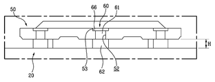
According to an aspect of the present invention for achieving the above object, the present invention provides a vehicle brake disk connected to a vehicle and rotated together to enable braking of the vehicle through friction with the brake pad, A plate assembly in which right and left side surfaces are selectively in contact with the brake pads and a plurality of ventilation channels extending radially with respect to the center are formed, and a plate assembly assembled to the plate assembly and connected to the vehicle to transmit rotational force of the vehicle to the plate assembly Wherein the plate assembly is coupled to the disc hub and the outer surface of the disc plate is in contact with the brake pad; a first plate coupled to the first plate and having an outer surface connected to the brake pad, A second plate which is in contact with the first plate, And a center plate which is coupled between the first plate and the second plate and is made of aluminum or an aluminum alloy and has a space rib protruding from at least one of the first plate and the second plate.
The center plate includes a ring-shaped center body having a center hole formed at the center thereof, and spacer ribs protruding from either the upper surface or the lower surface of the center body to closely contact with at least one of the first plate and the second plate. The spacer rib extends in a curved direction and is formed radially with respect to a center of the center hole.
The outer surfaces of the spacer ribs of the center plate and the outer surfaces of the first plate and the second plate closely contacting the spacer ribs are formed with fastening protrusions and fastening grooves corresponding to each other to prevent slippage during the rotation of the plate assembly.
The first plate, the second plate, and the center plate have first fastening holes, second fastening holes, and center fastening holes formed at positions corresponding to each other, and are assembled by fastening assembly.
The plurality of spacer ribs formed around the center plate are alternately formed with the fastening protrusions and the center fastening holes.
The fastener assembly includes a cylindrical center piece inserted into the first fastener, the second fastener, and the center fastener, an elastic member inserted into the center piece, and a second fastener, And a pair of fastening bolts inserted into both sides of the center piece through fastening holes and screwed to the inner circumferential surface of the center piece.
The disk hub is made of aluminum or an aluminum alloy and is coupled to the plate assembly to be spaced from the plate assembly.
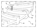
The disk hub and the plate assembly are coupled to each other by a floating assembly. The floating assembly includes a center member having a center hole formed therein. The plate assembly is inserted into one end of the center hole of the center member, And a floating nut which is fastened to the floating bolt at the other side of the floating assembly of the first plate, wherein the center member is provided with a spacer part, and the floating assembly is assembled The spacer portion is positioned between the bottom surface of the disk hub and the outer surface of the first plate so that the distance between the disk hub and the first plate is equal to the thickness of the spacer portion.
The head of the floating bolt is inserted into the seating groove of the disk hub, and the head of the floating bolt and the outer surface of the disk hub are continuous with each other.
A heat dissipating slit or a plurality of heat dissipating holes are formed in the first plate, the second plate, and the center plate at positions corresponding to each other, and the heat dissipating slit is formed along a curved path extending radially.
The following effects can be expected in the vehicle brake disc according to the present invention as described above.
In the present invention, since the center plate and the disc hub, which are not in contact with the brake pads, are made of a lightweight material such as aluminum among the parts constituting the vehicle brake disc, the brake disc is lightened, .
In addition, the weight reduction of the vehicle brake disk reduces the driving loss of the driving shaft, resulting in an improvement in fuel economy and output of the vehicle.
In the present invention, the center plate and the disk hub, which are made of aluminum excellent in heat dissipation property, are included to improve the overall heat dissipation. Particularly, the center plate is positioned between the first plate and the second plate, The frictional heat of the first plate and the second plate generated in the first plate is more efficiently removed.
Further, by improving the heat radiation performance, the strain caused by heat of each component constituting the brake disk is lowered and the durability of the brake disk is improved.
In addition, in the present invention, the floating assembly is spaced apart from the disk hub and the plate assembly to form a heat dissipating space therebetween, and the spacer rib provided on the center plate includes a plurality of ventilation channels between the first plate and the second plate, So that more efficient heat dissipation can be performed, and the heat radiation efficiency of the vehicle brake disk can be further improved.
Further, in the present invention, when the vehicle brake disc is worn by a limit value or more, only the first plate and the second plate need to be replaced without replacing the entire brake disk for a vehicle, so that waste of parts is reduced, Is reduced.
In addition, since the disk hub constituting the vehicle brake disk can be detached from the brake disk, the disk hub can be replaced to fit the desired vehicle, so that the vehicle brake disk can be attached to a wider range of vehicles, There is an effect to be improved.
1 is a perspective view showing a configuration of a preferred embodiment of a vehicle brake disc according to the present invention.
2 is an exploded perspective view showing a configuration of an embodiment of the present invention.
3 is a perspective view showing a configuration of a center plate constituting an embodiment of the present invention.
FIG. 4 is a front view showing a coupling structure between a disk hub and a plate assembly constituting an embodiment of the present invention; FIG.
5 is an exploded perspective view showing a configuration of a floating assembly connecting between a disk hub and a plate assembly constituting an embodiment of the present invention.
6 is a bottom perspective view showing the bottom structure of the embodiment of the present invention.
FIG. 7 is a perspective view showing a structure of a fastener assembly for coupling a center plate and a plate assembly constituting an embodiment of the present invention. FIG.
DETAILED DESCRIPTION OF THE PREFERRED EMBODIMENTS Hereinafter, specific embodiments of a vehicle brake disc according to the present invention will be described in detail with reference to the accompanying drawings.
Fig. 1 is a perspective view showing a construction of a preferred embodiment of a vehicle brake disc according to the present invention, and Fig. 2 is an exploded perspective view showing the construction of an embodiment of the present invention.
As shown in these drawings, a vehicle brake disk according to the present invention is connected to a vehicle and rotates together to selectively enable braking of the vehicle through friction with a brake pad (not shown). As described below, A plurality of parts are assembled.
The vehicle brake disc mainly includes a plate assembly (not designated) and a
The right and left side surfaces of the plate assembly are selectively in contact with the brake pads and a plurality of ventilation channels extending radially with respect to the center are formed to improve heat dissipation. The ventilation channel is formed by a
The plate assembly includes a
The
A plurality of
A
Although not shown, a first fastening groove is formed on the bottom surface of the
A second plate (40) is positioned on the other side of the first plate (20). The
The
A plurality of second fastening holes 44 and a second fastening groove 46 are formed in the
The second fastening hole (44) and the second fastening groove (46) are alternately formed around the second body (41).
A
More specifically, the
For this, the
In the
On the upper surface of the
The assembly between the
A
The central
Here, since the first
As described above, the plate assembly is composed of a
A
The
The floating
A
7, the
The
In addition, the
Meanwhile, the
In Fig. 5, the configuration of the floating assembly is shown in an exploded perspective view. As shown, the floating
At this time, the
More precisely, when the floating
A floating
That is, the floating
The floating
In the present embodiment, the floating
Hereinafter, the operation of the vehicle brake disk according to the present invention will be described in detail with reference to the drawings.
First, a process of assembling a brake disc for a vehicle according to the present invention will be described. A plate assembly constituting a brake disc for a vehicle is assembled. That is, the
At this time, a
In this state, the
In this state, the
The
Next, the process of assembling the
In this state, the floating
Next, the operation of the vehicle brake disk according to the present invention will be described. When the vehicle is driven, the
Then, when the driver operates the brake, the flap pad moves in the direction of the plate assembly to cause friction with the
At this time, during the operation of the brake, friction between the plate assembly and the brake pad is transmitted to the
Finally, the heat dissipation structure of the brake disk for a vehicle according to the present invention will be described. The plate assembly is primarily heat-dissipated by an aluminum-made
In addition, the first
A space is formed between the
As described above, since the vehicle brake disc according to the present invention is provided with various heat dissipating means, the heat dissipation performance of the entire brake disk for a vehicle is improved.
It is to be understood that the invention is not limited to the disclosed embodiment, but is capable of many modifications and variations within the scope of the appended claims. It is self-evident.
20: first plate 30: center plate
40: second plate 50: disk hub
60: Floating assembly
Claims (10)
A plate assembly in which right and left side surfaces are selectively in contact with the brake pads and a plurality of ventilation channels extending radially with respect to the center are formed,
And a disk hub assembled to the plate assembly and connected to the vehicle to transmit rotational force of the vehicle to the plate assembly,
A disk-shaped first plate coupled to the disk hub and having an outer surface in contact with the brake pad,
A second plate coupled to the first plate and having an outer surface in contact with the brake pad,
And a center plate coupled between the first plate and the second plate and made of aluminum or an aluminum alloy and having a space rib protruding from the first plate or the second plate in at least one direction of the first plate or the second plate, ≪ / RTI >
A cylindrical center piece inserted into the first fastening hole, the second fastening hole, and the center fastening hole;
An elastic member inserted into the center piece,
And a pair of fastening bolts inserted into both sides of the center piece through the first fastening hole and the second fastening hole and screwed to the inner circumferential surface of the center piece, respectively.
A center member having a center hole formed therein,
A floating bolt through which a floating assembly part of the disk hub, a center hole of the center member, and a floating assembly hole of the first plate, respectively,
And a floating nut fastened to the floating bolt on the other side of the floating assembly of the first plate,
Wherein the center member is provided with a spacer portion so that when the floating assembly is assembled, the spacer portion is positioned between the bottom surface of the disk hub and the outer surface of the first plate such that a distance between the disk hub and the first plate is spaced by the thickness of the spacer portion. A brake disk for a vehicle.
Priority Applications (1)
| Application Number | Priority Date | Filing Date | Title |
|---|---|---|---|
| KR1020120118928A KR20140052616A (en) | 2012-10-25 | 2012-10-25 | Brake disk for vehicle |
Applications Claiming Priority (1)
| Application Number | Priority Date | Filing Date | Title |
|---|---|---|---|
| KR1020120118928A KR20140052616A (en) | 2012-10-25 | 2012-10-25 | Brake disk for vehicle |
Publications (1)
| Publication Number | Publication Date |
|---|---|
| KR20140052616A true KR20140052616A (en) | 2014-05-07 |
Family
ID=50885826
Family Applications (1)
| Application Number | Title | Priority Date | Filing Date |
|---|---|---|---|
| KR1020120118928A KR20140052616A (en) | 2012-10-25 | 2012-10-25 | Brake disk for vehicle |
Country Status (1)
| Country | Link |
|---|---|
| KR (1) | KR20140052616A (en) |
Cited By (8)
| Publication number | Priority date | Publication date | Assignee | Title |
|---|---|---|---|---|
| KR20160100758A (en) * | 2015-02-16 | 2016-08-24 | 서한산업(주) | A Brake Disc |
| CN106870606A (en) * | 2015-12-11 | 2017-06-20 | Posco公司 | Attached type potassium steel brake disc |
| CN108317194A (en) * | 2018-03-26 | 2018-07-24 | 湖南世鑫新材料有限公司 | Bullet train axle-mounted brake disk component |
| CN109236902A (en) * | 2018-10-31 | 2019-01-18 | 福建省泉通摩托车配件有限公司 | A kind of motorcycle disk brake |
| KR101985622B1 (en) * | 2018-07-16 | 2019-06-03 | 옥재동 | Discs combined with cast iron and aluminum |
| CN109869423A (en) * | 2019-03-21 | 2019-06-11 | 中国铁道科学研究院集团有限公司 | A kind of carbon pottery axle-mounted brake disk suitable for high-speed EMUs |
| CN111301367A (en) * | 2020-03-30 | 2020-06-19 | 吉林大学 | Bidirectional floating fixing structure for carbon fiber composite brake disc |
| CN113513549A (en) * | 2020-04-09 | 2021-10-19 | 北京优加特福乐科技有限公司 | Internal circulation water-cooling brake |
-
2012
- 2012-10-25 KR KR1020120118928A patent/KR20140052616A/en active IP Right Grant
Cited By (12)
| Publication number | Priority date | Publication date | Assignee | Title |
|---|---|---|---|---|
| KR20160100758A (en) * | 2015-02-16 | 2016-08-24 | 서한산업(주) | A Brake Disc |
| CN106870606A (en) * | 2015-12-11 | 2017-06-20 | Posco公司 | Attached type potassium steel brake disc |
| US10018236B2 (en) | 2015-12-11 | 2018-07-10 | Posco | Attachable high-Mn steel brake disk |
| CN106870606B (en) * | 2015-12-11 | 2019-02-22 | Posco公司 | Attached type potassium steel brake disc |
| CN108317194A (en) * | 2018-03-26 | 2018-07-24 | 湖南世鑫新材料有限公司 | Bullet train axle-mounted brake disk component |
| CN108317194B (en) * | 2018-03-26 | 2024-03-12 | 湖南世鑫新材料有限公司 | Shaft-mounted brake disc assembly for high-speed train |
| KR101985622B1 (en) * | 2018-07-16 | 2019-06-03 | 옥재동 | Discs combined with cast iron and aluminum |
| CN109236902A (en) * | 2018-10-31 | 2019-01-18 | 福建省泉通摩托车配件有限公司 | A kind of motorcycle disk brake |
| CN109869423A (en) * | 2019-03-21 | 2019-06-11 | 中国铁道科学研究院集团有限公司 | A kind of carbon pottery axle-mounted brake disk suitable for high-speed EMUs |
| CN111301367A (en) * | 2020-03-30 | 2020-06-19 | 吉林大学 | Bidirectional floating fixing structure for carbon fiber composite brake disc |
| CN113513549A (en) * | 2020-04-09 | 2021-10-19 | 北京优加特福乐科技有限公司 | Internal circulation water-cooling brake |
| CN113513549B (en) * | 2020-04-09 | 2023-03-21 | 北京优加特福乐科技有限公司 | Internal circulation water-cooling brake |
Similar Documents
| Publication | Publication Date | Title |
|---|---|---|
| KR20140052616A (en) | Brake disk for vehicle | |
| US8978843B2 (en) | Brake disk assembly | |
| KR101294035B1 (en) | Structure of axle assembly for a driving wheel | |
| KR101964125B1 (en) | Brake Disc | |
| KR20130019127A (en) | Brake disc using different materials | |
| EP2978990A1 (en) | Floating brake drum and hub assembly | |
| WO2019128458A1 (en) | Shaft-mounted brake disc device for railway vehicle | |
| JP2014092267A (en) | Brake disk for vehicle | |
| US20160245344A1 (en) | Two piece clutch reaction plate | |
| US20130240309A1 (en) | Brake Disk Assembly | |
| KR102150231B1 (en) | Brake disk of involute spur mounting structure | |
| KR20080024723A (en) | Fastening structure of disk and hub in vehicles | |
| CN210397520U (en) | Brake disc casting structure based on automobile casting | |
| KR101352498B1 (en) | Break disk rotor with hybrid sealing material for vehicle | |
| EP3404283B1 (en) | Extended torque tube | |
| KR101543128B1 (en) | Disc brake device combined parking brake with different materials | |
| CN210484462U (en) | Brake disc | |
| US20160069406A1 (en) | Floating brake drum and hat assembly | |
| KR20150065040A (en) | Separatable brake disk, wheel bearing assembly provided with the same and method of restricting runout of brake disk | |
| CN201944153U (en) | Brake plate for two-wheeled motorcycle | |
| CN211852601U (en) | Floating brake device and motor vehicle | |
| US20190219115A1 (en) | Brake disc | |
| BRPI0717626B1 (en) | CLUTCH FRICTION DISK AND MANUFACTURING PROCESS OF A CLUTCH FRICTION DISK | |
| KR20160100758A (en) | A Brake Disc | |
| CN103352936A (en) | Automobile brake hub |
Legal Events
| Date | Code | Title | Description |
|---|---|---|---|
| A201 | Request for examination | ||
| E902 | Notification of reason for refusal | ||
| E902 | Notification of reason for refusal | ||
| E701 | Decision to grant or registration of patent right |