KR20140036282A - Method and device for the layered production of thin volume grid stacks, and beam combiner for a holographic display - Google Patents
Method and device for the layered production of thin volume grid stacks, and beam combiner for a holographic display Download PDFInfo
- Publication number
- KR20140036282A KR20140036282A KR1020137035114A KR20137035114A KR20140036282A KR 20140036282 A KR20140036282 A KR 20140036282A KR 1020137035114 A KR1020137035114 A KR 1020137035114A KR 20137035114 A KR20137035114 A KR 20137035114A KR 20140036282 A KR20140036282 A KR 20140036282A
- Authority
- KR
- South Korea
- Prior art keywords
- grating
- recording medium
- light
- predetermined
- azm
- Prior art date
Links
- 238000000034 method Methods 0.000 title claims abstract description 97
- 238000004519 manufacturing process Methods 0.000 title description 5
- 238000009792 diffusion process Methods 0.000 claims abstract description 29
- 230000002123 temporal effect Effects 0.000 claims abstract description 28
- 230000001427 coherent effect Effects 0.000 claims abstract description 22
- 230000015572 biosynthetic process Effects 0.000 claims abstract description 19
- 230000002452 interceptive effect Effects 0.000 claims abstract description 19
- 238000002834 transmittance Methods 0.000 claims abstract description 11
- 230000006870 function Effects 0.000 claims description 124
- 230000003287 optical effect Effects 0.000 claims description 40
- 238000005286 illumination Methods 0.000 claims description 36
- 238000009826 distribution Methods 0.000 claims description 33
- 230000003595 spectral effect Effects 0.000 claims description 33
- 238000006243 chemical reaction Methods 0.000 claims description 30
- 238000006073 displacement reaction Methods 0.000 claims description 30
- 239000003999 initiator Substances 0.000 claims description 18
- 230000005540 biological transmission Effects 0.000 claims description 17
- 230000000694 effects Effects 0.000 claims description 16
- 230000035945 sensitivity Effects 0.000 claims description 15
- 230000001419 dependent effect Effects 0.000 claims description 14
- 239000000463 material Substances 0.000 claims description 14
- 238000002604 ultrasonography Methods 0.000 claims description 12
- 101100175003 Oryza sativa subsp. japonica RGB1 gene Proteins 0.000 claims description 9
- 239000003795 chemical substances by application Substances 0.000 claims description 8
- 230000004913 activation Effects 0.000 claims description 7
- 238000012546 transfer Methods 0.000 claims description 7
- 239000003086 colorant Substances 0.000 claims description 6
- 229920000159 gelatin Polymers 0.000 claims description 6
- 239000008273 gelatin Substances 0.000 claims description 6
- 238000005259 measurement Methods 0.000 claims description 6
- 238000000926 separation method Methods 0.000 claims description 6
- 108010010803 Gelatin Proteins 0.000 claims description 5
- 235000019322 gelatine Nutrition 0.000 claims description 5
- 235000011852 gelatine desserts Nutrition 0.000 claims description 5
- 239000004973 liquid crystal related substance Substances 0.000 claims description 5
- 239000002096 quantum dot Substances 0.000 claims description 5
- 239000000126 substance Substances 0.000 claims description 5
- 230000009467 reduction Effects 0.000 claims description 4
- 239000000203 mixture Substances 0.000 claims description 2
- 238000004611 spectroscopical analysis Methods 0.000 claims description 2
- 230000007480 spreading Effects 0.000 claims description 2
- 238000003892 spreading Methods 0.000 claims description 2
- 238000004020 luminiscence type Methods 0.000 claims 1
- 230000003362 replicative effect Effects 0.000 claims 1
- 238000007704 wet chemistry method Methods 0.000 claims 1
- 230000008569 process Effects 0.000 description 11
- 238000001228 spectrum Methods 0.000 description 11
- 239000000758 substrate Substances 0.000 description 11
- 230000008859 change Effects 0.000 description 9
- 238000010521 absorption reaction Methods 0.000 description 8
- 229920002120 photoresistant polymer Polymers 0.000 description 8
- 230000010287 polarization Effects 0.000 description 8
- 230000000737 periodic effect Effects 0.000 description 7
- 230000010363 phase shift Effects 0.000 description 7
- 238000013461 design Methods 0.000 description 6
- 239000005337 ground glass Substances 0.000 description 6
- 230000010076 replication Effects 0.000 description 6
- 230000008901 benefit Effects 0.000 description 5
- 230000007423 decrease Effects 0.000 description 5
- 238000013507 mapping Methods 0.000 description 5
- 230000005855 radiation Effects 0.000 description 5
- 239000000853 adhesive Substances 0.000 description 4
- 230000001070 adhesive effect Effects 0.000 description 4
- 238000007654 immersion Methods 0.000 description 4
- 238000003475 lamination Methods 0.000 description 4
- 238000004599 local-density approximation Methods 0.000 description 4
- 230000009471 action Effects 0.000 description 3
- 239000006059 cover glass Substances 0.000 description 3
- 239000011521 glass Substances 0.000 description 3
- 238000006722 reduction reaction Methods 0.000 description 3
- 230000002829 reductive effect Effects 0.000 description 3
- 238000004458 analytical method Methods 0.000 description 2
- 230000003247 decreasing effect Effects 0.000 description 2
- 238000010586 diagram Methods 0.000 description 2
- 239000010408 film Substances 0.000 description 2
- 238000000799 fluorescence microscopy Methods 0.000 description 2
- 230000006872 improvement Effects 0.000 description 2
- 230000000670 limiting effect Effects 0.000 description 2
- 238000000386 microscopy Methods 0.000 description 2
- 238000000399 optical microscopy Methods 0.000 description 2
- 239000002245 particle Substances 0.000 description 2
- 229920000642 polymer Polymers 0.000 description 2
- 125000006850 spacer group Chemical group 0.000 description 2
- 238000003860 storage Methods 0.000 description 2
- 230000001360 synchronised effect Effects 0.000 description 2
- 230000007704 transition Effects 0.000 description 2
- 230000005526 G1 to G0 transition Effects 0.000 description 1
- 238000000149 argon plasma sintering Methods 0.000 description 1
- 238000003491 array Methods 0.000 description 1
- 238000004364 calculation method Methods 0.000 description 1
- 239000003638 chemical reducing agent Substances 0.000 description 1
- 150000001875 compounds Chemical class 0.000 description 1
- 230000008602 contraction Effects 0.000 description 1
- 238000007796 conventional method Methods 0.000 description 1
- 238000012937 correction Methods 0.000 description 1
- 230000009849 deactivation Effects 0.000 description 1
- 238000005137 deposition process Methods 0.000 description 1
- 238000001514 detection method Methods 0.000 description 1
- 238000011161 development Methods 0.000 description 1
- 230000029087 digestion Effects 0.000 description 1
- 238000007598 dipping method Methods 0.000 description 1
- 238000005315 distribution function Methods 0.000 description 1
- 238000011156 evaluation Methods 0.000 description 1
- 238000001914 filtration Methods 0.000 description 1
- 230000010354 integration Effects 0.000 description 1
- 239000007788 liquid Substances 0.000 description 1
- 238000001459 lithography Methods 0.000 description 1
- 230000004807 localization Effects 0.000 description 1
- 230000000873 masking effect Effects 0.000 description 1
- 238000005457 optimization Methods 0.000 description 1
- 230000036961 partial effect Effects 0.000 description 1
- 230000035515 penetration Effects 0.000 description 1
- 239000006089 photosensitive glass Substances 0.000 description 1
- 230000029553 photosynthesis Effects 0.000 description 1
- 238000010672 photosynthesis Methods 0.000 description 1
- 238000012545 processing Methods 0.000 description 1
- 230000000644 propagated effect Effects 0.000 description 1
- 230000001902 propagating effect Effects 0.000 description 1
- 230000003068 static effect Effects 0.000 description 1
- 239000010409 thin film Substances 0.000 description 1
- 230000009466 transformation Effects 0.000 description 1
- 238000000844 transformation Methods 0.000 description 1
Images


Classifications
-
- G—PHYSICS
- G03—PHOTOGRAPHY; CINEMATOGRAPHY; ANALOGOUS TECHNIQUES USING WAVES OTHER THAN OPTICAL WAVES; ELECTROGRAPHY; HOLOGRAPHY
- G03H—HOLOGRAPHIC PROCESSES OR APPARATUS
- G03H1/00—Holographic processes or apparatus using light, infrared or ultraviolet waves for obtaining holograms or for obtaining an image from them; Details peculiar thereto
- G03H1/02—Details of features involved during the holographic process; Replication of holograms without interference recording
- G03H1/024—Hologram nature or properties
- G03H1/0248—Volume holograms
-
- G—PHYSICS
- G03—PHOTOGRAPHY; CINEMATOGRAPHY; ANALOGOUS TECHNIQUES USING WAVES OTHER THAN OPTICAL WAVES; ELECTROGRAPHY; HOLOGRAPHY
- G03H—HOLOGRAPHIC PROCESSES OR APPARATUS
- G03H1/00—Holographic processes or apparatus using light, infrared or ultraviolet waves for obtaining holograms or for obtaining an image from them; Details peculiar thereto
- G03H1/04—Processes or apparatus for producing holograms
-
- B—PERFORMING OPERATIONS; TRANSPORTING
- B29—WORKING OF PLASTICS; WORKING OF SUBSTANCES IN A PLASTIC STATE IN GENERAL
- B29D—PRODUCING PARTICULAR ARTICLES FROM PLASTICS OR FROM SUBSTANCES IN A PLASTIC STATE
- B29D11/00—Producing optical elements, e.g. lenses or prisms
- B29D11/0074—Production of other optical elements not provided for in B29D11/00009- B29D11/0073
- B29D11/00769—Producing diffraction gratings
-
- G—PHYSICS
- G02—OPTICS
- G02B—OPTICAL ELEMENTS, SYSTEMS OR APPARATUS
- G02B27/00—Optical systems or apparatus not provided for by any of the groups G02B1/00 - G02B26/00, G02B30/00
- G02B27/42—Diffraction optics, i.e. systems including a diffractive element being designed for providing a diffractive effect
- G02B27/4233—Diffraction optics, i.e. systems including a diffractive element being designed for providing a diffractive effect having a diffractive element [DOE] contributing to a non-imaging application
-
- G—PHYSICS
- G02—OPTICS
- G02B—OPTICAL ELEMENTS, SYSTEMS OR APPARATUS
- G02B5/00—Optical elements other than lenses
- G02B5/18—Diffraction gratings
-
- G—PHYSICS
- G02—OPTICS
- G02B—OPTICAL ELEMENTS, SYSTEMS OR APPARATUS
- G02B5/00—Optical elements other than lenses
- G02B5/18—Diffraction gratings
- G02B5/1847—Manufacturing methods
- G02B5/1857—Manufacturing methods using exposure or etching means, e.g. holography, photolithography, exposure to electron or ion beams
-
- G—PHYSICS
- G02—OPTICS
- G02B—OPTICAL ELEMENTS, SYSTEMS OR APPARATUS
- G02B5/00—Optical elements other than lenses
- G02B5/32—Holograms used as optical elements
-
- G—PHYSICS
- G03—PHOTOGRAPHY; CINEMATOGRAPHY; ANALOGOUS TECHNIQUES USING WAVES OTHER THAN OPTICAL WAVES; ELECTROGRAPHY; HOLOGRAPHY
- G03H—HOLOGRAPHIC PROCESSES OR APPARATUS
- G03H1/00—Holographic processes or apparatus using light, infrared or ultraviolet waves for obtaining holograms or for obtaining an image from them; Details peculiar thereto
- G03H1/02—Details of features involved during the holographic process; Replication of holograms without interference recording
-
- G—PHYSICS
- G03—PHOTOGRAPHY; CINEMATOGRAPHY; ANALOGOUS TECHNIQUES USING WAVES OTHER THAN OPTICAL WAVES; ELECTROGRAPHY; HOLOGRAPHY
- G03H—HOLOGRAPHIC PROCESSES OR APPARATUS
- G03H1/00—Holographic processes or apparatus using light, infrared or ultraviolet waves for obtaining holograms or for obtaining an image from them; Details peculiar thereto
- G03H1/04—Processes or apparatus for producing holograms
- G03H1/0402—Recording geometries or arrangements
-
- G—PHYSICS
- G03—PHOTOGRAPHY; CINEMATOGRAPHY; ANALOGOUS TECHNIQUES USING WAVES OTHER THAN OPTICAL WAVES; ELECTROGRAPHY; HOLOGRAPHY
- G03H—HOLOGRAPHIC PROCESSES OR APPARATUS
- G03H1/00—Holographic processes or apparatus using light, infrared or ultraviolet waves for obtaining holograms or for obtaining an image from them; Details peculiar thereto
- G03H1/04—Processes or apparatus for producing holograms
- G03H1/0465—Particular recording light; Beam shape or geometry
-
- G—PHYSICS
- G03—PHOTOGRAPHY; CINEMATOGRAPHY; ANALOGOUS TECHNIQUES USING WAVES OTHER THAN OPTICAL WAVES; ELECTROGRAPHY; HOLOGRAPHY
- G03H—HOLOGRAPHIC PROCESSES OR APPARATUS
- G03H1/00—Holographic processes or apparatus using light, infrared or ultraviolet waves for obtaining holograms or for obtaining an image from them; Details peculiar thereto
- G03H1/26—Processes or apparatus specially adapted to produce multiple sub- holograms or to obtain images from them, e.g. multicolour technique
- G03H1/2645—Multiplexing processes, e.g. aperture, shift, or wavefront multiplexing
-
- G—PHYSICS
- G02—OPTICS
- G02F—OPTICAL DEVICES OR ARRANGEMENTS FOR THE CONTROL OF LIGHT BY MODIFICATION OF THE OPTICAL PROPERTIES OF THE MEDIA OF THE ELEMENTS INVOLVED THEREIN; NON-LINEAR OPTICS; FREQUENCY-CHANGING OF LIGHT; OPTICAL LOGIC ELEMENTS; OPTICAL ANALOGUE/DIGITAL CONVERTERS
- G02F1/00—Devices or arrangements for the control of the intensity, colour, phase, polarisation or direction of light arriving from an independent light source, e.g. switching, gating or modulating; Non-linear optics
- G02F1/01—Devices or arrangements for the control of the intensity, colour, phase, polarisation or direction of light arriving from an independent light source, e.g. switching, gating or modulating; Non-linear optics for the control of the intensity, phase, polarisation or colour
- G02F1/13—Devices or arrangements for the control of the intensity, colour, phase, polarisation or direction of light arriving from an independent light source, e.g. switching, gating or modulating; Non-linear optics for the control of the intensity, phase, polarisation or colour based on liquid crystals, e.g. single liquid crystal display cells
- G02F1/133—Constructional arrangements; Operation of liquid crystal cells; Circuit arrangements
- G02F1/1333—Constructional arrangements; Manufacturing methods
- G02F1/1334—Constructional arrangements; Manufacturing methods based on polymer dispersed liquid crystals, e.g. microencapsulated liquid crystals
- G02F1/13342—Holographic polymer dispersed liquid crystals
-
- G—PHYSICS
- G03—PHOTOGRAPHY; CINEMATOGRAPHY; ANALOGOUS TECHNIQUES USING WAVES OTHER THAN OPTICAL WAVES; ELECTROGRAPHY; HOLOGRAPHY
- G03H—HOLOGRAPHIC PROCESSES OR APPARATUS
- G03H1/00—Holographic processes or apparatus using light, infrared or ultraviolet waves for obtaining holograms or for obtaining an image from them; Details peculiar thereto
- G03H1/0005—Adaptation of holography to specific applications
- G03H1/0011—Adaptation of holography to specific applications for security or authentication
-
- G—PHYSICS
- G03—PHOTOGRAPHY; CINEMATOGRAPHY; ANALOGOUS TECHNIQUES USING WAVES OTHER THAN OPTICAL WAVES; ELECTROGRAPHY; HOLOGRAPHY
- G03H—HOLOGRAPHIC PROCESSES OR APPARATUS
- G03H1/00—Holographic processes or apparatus using light, infrared or ultraviolet waves for obtaining holograms or for obtaining an image from them; Details peculiar thereto
- G03H1/04—Processes or apparatus for producing holograms
- G03H1/0486—Improving or monitoring the quality of the record, e.g. by compensating distortions, aberrations
-
- G—PHYSICS
- G03—PHOTOGRAPHY; CINEMATOGRAPHY; ANALOGOUS TECHNIQUES USING WAVES OTHER THAN OPTICAL WAVES; ELECTROGRAPHY; HOLOGRAPHY
- G03H—HOLOGRAPHIC PROCESSES OR APPARATUS
- G03H1/00—Holographic processes or apparatus using light, infrared or ultraviolet waves for obtaining holograms or for obtaining an image from them; Details peculiar thereto
- G03H1/04—Processes or apparatus for producing holograms
- G03H1/06—Processes or apparatus for producing holograms using incoherent light
-
- G—PHYSICS
- G03—PHOTOGRAPHY; CINEMATOGRAPHY; ANALOGOUS TECHNIQUES USING WAVES OTHER THAN OPTICAL WAVES; ELECTROGRAPHY; HOLOGRAPHY
- G03H—HOLOGRAPHIC PROCESSES OR APPARATUS
- G03H1/00—Holographic processes or apparatus using light, infrared or ultraviolet waves for obtaining holograms or for obtaining an image from them; Details peculiar thereto
- G03H1/04—Processes or apparatus for producing holograms
- G03H1/20—Copying holograms by holographic, i.e. optical means
-
- G—PHYSICS
- G03—PHOTOGRAPHY; CINEMATOGRAPHY; ANALOGOUS TECHNIQUES USING WAVES OTHER THAN OPTICAL WAVES; ELECTROGRAPHY; HOLOGRAPHY
- G03H—HOLOGRAPHIC PROCESSES OR APPARATUS
- G03H1/00—Holographic processes or apparatus using light, infrared or ultraviolet waves for obtaining holograms or for obtaining an image from them; Details peculiar thereto
- G03H1/22—Processes or apparatus for obtaining an optical image from holograms
- G03H1/2294—Addressing the hologram to an active spatial light modulator
-
- G—PHYSICS
- G03—PHOTOGRAPHY; CINEMATOGRAPHY; ANALOGOUS TECHNIQUES USING WAVES OTHER THAN OPTICAL WAVES; ELECTROGRAPHY; HOLOGRAPHY
- G03H—HOLOGRAPHIC PROCESSES OR APPARATUS
- G03H1/00—Holographic processes or apparatus using light, infrared or ultraviolet waves for obtaining holograms or for obtaining an image from them; Details peculiar thereto
- G03H1/26—Processes or apparatus specially adapted to produce multiple sub- holograms or to obtain images from them, e.g. multicolour technique
- G03H1/2645—Multiplexing processes, e.g. aperture, shift, or wavefront multiplexing
- G03H1/265—Angle multiplexing; Multichannel holograms
-
- G—PHYSICS
- G03—PHOTOGRAPHY; CINEMATOGRAPHY; ANALOGOUS TECHNIQUES USING WAVES OTHER THAN OPTICAL WAVES; ELECTROGRAPHY; HOLOGRAPHY
- G03H—HOLOGRAPHIC PROCESSES OR APPARATUS
- G03H1/00—Holographic processes or apparatus using light, infrared or ultraviolet waves for obtaining holograms or for obtaining an image from them; Details peculiar thereto
- G03H1/26—Processes or apparatus specially adapted to produce multiple sub- holograms or to obtain images from them, e.g. multicolour technique
- G03H1/28—Processes or apparatus specially adapted to produce multiple sub- holograms or to obtain images from them, e.g. multicolour technique superimposed holograms only
-
- G—PHYSICS
- G03—PHOTOGRAPHY; CINEMATOGRAPHY; ANALOGOUS TECHNIQUES USING WAVES OTHER THAN OPTICAL WAVES; ELECTROGRAPHY; HOLOGRAPHY
- G03H—HOLOGRAPHIC PROCESSES OR APPARATUS
- G03H1/00—Holographic processes or apparatus using light, infrared or ultraviolet waves for obtaining holograms or for obtaining an image from them; Details peculiar thereto
- G03H1/0005—Adaptation of holography to specific applications
- G03H2001/0033—Adaptation of holography to specific applications in hologrammetry for measuring or analysing
-
- G—PHYSICS
- G03—PHOTOGRAPHY; CINEMATOGRAPHY; ANALOGOUS TECHNIQUES USING WAVES OTHER THAN OPTICAL WAVES; ELECTROGRAPHY; HOLOGRAPHY
- G03H—HOLOGRAPHIC PROCESSES OR APPARATUS
- G03H1/00—Holographic processes or apparatus using light, infrared or ultraviolet waves for obtaining holograms or for obtaining an image from them; Details peculiar thereto
- G03H1/0005—Adaptation of holography to specific applications
- G03H2001/005—Adaptation of holography to specific applications in microscopy, e.g. digital holographic microscope [DHM]
-
- G—PHYSICS
- G03—PHOTOGRAPHY; CINEMATOGRAPHY; ANALOGOUS TECHNIQUES USING WAVES OTHER THAN OPTICAL WAVES; ELECTROGRAPHY; HOLOGRAPHY
- G03H—HOLOGRAPHIC PROCESSES OR APPARATUS
- G03H1/00—Holographic processes or apparatus using light, infrared or ultraviolet waves for obtaining holograms or for obtaining an image from them; Details peculiar thereto
- G03H1/04—Processes or apparatus for producing holograms
- G03H1/0402—Recording geometries or arrangements
- G03H2001/0439—Recording geometries or arrangements for recording Holographic Optical Element [HOE]
-
- G—PHYSICS
- G03—PHOTOGRAPHY; CINEMATOGRAPHY; ANALOGOUS TECHNIQUES USING WAVES OTHER THAN OPTICAL WAVES; ELECTROGRAPHY; HOLOGRAPHY
- G03H—HOLOGRAPHIC PROCESSES OR APPARATUS
- G03H1/00—Holographic processes or apparatus using light, infrared or ultraviolet waves for obtaining holograms or for obtaining an image from them; Details peculiar thereto
- G03H1/04—Processes or apparatus for producing holograms
- G03H1/0465—Particular recording light; Beam shape or geometry
- G03H2001/0467—Gated recording using pulsed or low coherence light source, e.g. light in flight, first arriving light
-
- G—PHYSICS
- G03—PHOTOGRAPHY; CINEMATOGRAPHY; ANALOGOUS TECHNIQUES USING WAVES OTHER THAN OPTICAL WAVES; ELECTROGRAPHY; HOLOGRAPHY
- G03H—HOLOGRAPHIC PROCESSES OR APPARATUS
- G03H1/00—Holographic processes or apparatus using light, infrared or ultraviolet waves for obtaining holograms or for obtaining an image from them; Details peculiar thereto
- G03H1/26—Processes or apparatus specially adapted to produce multiple sub- holograms or to obtain images from them, e.g. multicolour technique
- G03H2001/2605—Arrangement of the sub-holograms, e.g. partial overlapping
- G03H2001/261—Arrangement of the sub-holograms, e.g. partial overlapping in optical contact
- G03H2001/2615—Arrangement of the sub-holograms, e.g. partial overlapping in optical contact in physical contact, i.e. layered holograms
-
- G—PHYSICS
- G03—PHOTOGRAPHY; CINEMATOGRAPHY; ANALOGOUS TECHNIQUES USING WAVES OTHER THAN OPTICAL WAVES; ELECTROGRAPHY; HOLOGRAPHY
- G03H—HOLOGRAPHIC PROCESSES OR APPARATUS
- G03H1/00—Holographic processes or apparatus using light, infrared or ultraviolet waves for obtaining holograms or for obtaining an image from them; Details peculiar thereto
- G03H1/26—Processes or apparatus specially adapted to produce multiple sub- holograms or to obtain images from them, e.g. multicolour technique
- G03H2001/2625—Nature of the sub-holograms
- G03H2001/264—One hologram being a HOE
-
- G—PHYSICS
- G03—PHOTOGRAPHY; CINEMATOGRAPHY; ANALOGOUS TECHNIQUES USING WAVES OTHER THAN OPTICAL WAVES; ELECTROGRAPHY; HOLOGRAPHY
- G03H—HOLOGRAPHIC PROCESSES OR APPARATUS
- G03H1/00—Holographic processes or apparatus using light, infrared or ultraviolet waves for obtaining holograms or for obtaining an image from them; Details peculiar thereto
- G03H1/26—Processes or apparatus specially adapted to produce multiple sub- holograms or to obtain images from them, e.g. multicolour technique
- G03H1/2645—Multiplexing processes, e.g. aperture, shift, or wavefront multiplexing
- G03H2001/266—Wavelength multiplexing
-
- G—PHYSICS
- G03—PHOTOGRAPHY; CINEMATOGRAPHY; ANALOGOUS TECHNIQUES USING WAVES OTHER THAN OPTICAL WAVES; ELECTROGRAPHY; HOLOGRAPHY
- G03H—HOLOGRAPHIC PROCESSES OR APPARATUS
- G03H2222/00—Light sources or light beam properties
- G03H2222/20—Coherence of the light source
- G03H2222/22—Spatial coherence
-
- G—PHYSICS
- G03—PHOTOGRAPHY; CINEMATOGRAPHY; ANALOGOUS TECHNIQUES USING WAVES OTHER THAN OPTICAL WAVES; ELECTROGRAPHY; HOLOGRAPHY
- G03H—HOLOGRAPHIC PROCESSES OR APPARATUS
- G03H2222/00—Light sources or light beam properties
- G03H2222/20—Coherence of the light source
- G03H2222/23—Temporal coherence
-
- G—PHYSICS
- G03—PHOTOGRAPHY; CINEMATOGRAPHY; ANALOGOUS TECHNIQUES USING WAVES OTHER THAN OPTICAL WAVES; ELECTROGRAPHY; HOLOGRAPHY
- G03H—HOLOGRAPHIC PROCESSES OR APPARATUS
- G03H2222/00—Light sources or light beam properties
- G03H2222/20—Coherence of the light source
- G03H2222/24—Low coherence light normally not allowing valuable record or reconstruction
-
- G—PHYSICS
- G03—PHOTOGRAPHY; CINEMATOGRAPHY; ANALOGOUS TECHNIQUES USING WAVES OTHER THAN OPTICAL WAVES; ELECTROGRAPHY; HOLOGRAPHY
- G03H—HOLOGRAPHIC PROCESSES OR APPARATUS
- G03H2222/00—Light sources or light beam properties
- G03H2222/35—Transverse intensity distribution of the light beam
-
- G—PHYSICS
- G03—PHOTOGRAPHY; CINEMATOGRAPHY; ANALOGOUS TECHNIQUES USING WAVES OTHER THAN OPTICAL WAVES; ELECTROGRAPHY; HOLOGRAPHY
- G03H—HOLOGRAPHIC PROCESSES OR APPARATUS
- G03H2222/00—Light sources or light beam properties
- G03H2222/40—Particular irradiation beam not otherwise provided for
- G03H2222/42—Reference beam at recording stage
-
- G—PHYSICS
- G03—PHOTOGRAPHY; CINEMATOGRAPHY; ANALOGOUS TECHNIQUES USING WAVES OTHER THAN OPTICAL WAVES; ELECTROGRAPHY; HOLOGRAPHY
- G03H—HOLOGRAPHIC PROCESSES OR APPARATUS
- G03H2223/00—Optical components
- G03H2223/23—Diffractive element
Abstract
본 발명은 노출광의 미리 정해진 파장(λ)에 감응하는 적어도 하나의 광감성 층을 포함하는 기록 매체(AZM)에서 노광에 의해 적어도 하나의 체적 격자(VG)의 층상 형성을 위한 방법 및 장치에 관한 것이다. 각각의 체적 격자(VG)는 기록 매체(AZM)에서 간섭성 광의 적어도 2개의 간섭 파면(WF1, WF2)에 의해 형성되고, 상기 파면들은 기록 매체(AZM)에서 미리 정해진 깊이(z)에 미리 정해진 각도(2θ)로 간섭 콘트라스트와 중첩된다. 기록 매체(AZM)에서 체적 격자(VG)의 굴절률- 및/또는 투과율 변조의 깊이(z)와 두께는 광 확산(z) 방향으로 간섭 파면(WF1, WF2)의 공간적 및/또는 시간적 간섭도(Γ)에 의해 조절된다. 또한, 본 발명은 홀로그래픽 디스플레이를 위한 빔 컴바이너 및 효율이 증가한 태양광 모듈에 관한 것이다. The present invention relates to a method and apparatus for layer formation of at least one volume grating (VG) by exposure in a recording medium (AZM) comprising at least one photosensitive layer sensitive to a predetermined wavelength (λ) of exposure light. will be. Each volume grating VG is formed by at least two interfering wavefronts WF1 and WF2 of coherent light in the recording medium AZM, which wavefronts are predetermined at a predetermined depth z in the recording medium AZM. It overlaps with the interference contrast at an angle 2θ. The depth z and thickness of the refractive index and / or transmittance modulation of the volume grating VG in the recording medium AZM are determined by the spatial and / or temporal coherence of the interference wavefronts WF1 and WF2 in the direction of light diffusion z. Γ). The invention also relates to a beam combiner for holographic displays and a solar module with increased efficiency.
Description
본 발명은 얇은 체적 격자 스택의 층상 형성을 위한 방법과 장치에 관한 것이다. 또한, 본 발명은 홀로그래픽 디스플레이를 위한 빔 컴바이너에 관한 것이다. The present invention relates to a method and apparatus for layer formation of thin volume grating stacks. The invention also relates to a beam combiner for a holographic display.
홀로그래픽 직시형 디스플레이의 제조 시 회절 광학 소자(DOE)는 특수한 역할을 한다. 대개 미리 정해진 두께를 갖는 투명 필름의 형태로 제공되는 상기 소자는 이미지 제공 수단, 예를 들어 대면적 광 변조기(SLM)로부터 입사하는 광 복사에 굴절에 의해서보다 회절 효과에 의해 영향을 미친다. 이로 인해 직시형 디스플레이에서 광 방향으로 SLM 후방에 배치되어 광빔에 간섭하는 소자의 두께는, 빔 경로에 바람직하게 렌즈, 프리즘 등과 같은 광 굴절 소자들을 이용하는 프로젝션 디스플레이에 비해 작게 유지될 수 있다. The diffractive optical element (DOE) plays a special role in the manufacture of holographic direct view displays. The device, usually provided in the form of a transparent film having a predetermined thickness, influences the diffraction effect rather than by refraction on the light radiation incident from the image providing means, for example a large area light modulator (SLM). This allows the thickness of the element disposed behind the SLM in the light direction to interfere with the light beam in the direct view display can be kept small compared to the projection display which preferably uses light refracting elements such as lenses, prisms, etc. in the beam path.
그러나 관찰자에게 3D 입체 영상 이미지를 제공하기 위해 필요한 SLM의 픽셀로부터 방사되는 광의 간섭은 다수의 박막형 DOE에 의해서만 달성될 수 있고, 상기 DOE들은 예를 들어 대면적 층 스택 형태로 SLM 후방에 배치된다. 이 경우 기술적인 이유에서, 다수의 연속하는 층들은 개별적으로보다 연속 매체에서 후속 결합에 의해, 예를 들어 접착에 의해 형성되는 것이 바람직한데, 그 이유는 이러한 공정에 의해 상이한 층들의 개별 표면 요소들의 상호 위치들이 예를 들어 수축에 의해 변경될 수 있기 때문이다. However, interference of light emitted from the pixels of the SLM required to provide the viewer with 3D stereoscopic imagery can only be achieved by multiple thin-film DOEs, which are placed behind the SLM, for example in the form of a large area stack. For technical reasons in this case, it is preferable that a plurality of successive layers are formed by subsequent bonding, for example by adhesion, in a continuous medium rather than individually, because of the process of the individual surface elements of the different layers This is because the mutual positions can be changed, for example by contraction.
SLM의 픽셀로부터 방사되는 광의 회절 효과에 의한 방향에 따른 그리고 파장에 따른 간섭을 위해 사용되는 구조는 표면 격자 또는 체적 격자일 수 있다. 일반적으로 3차원 격자 구조를 체적 격자라고 하고, 상기 입체 격자 구는 조명 광의 파장에 비해 두꺼운 매체에 기록된다. 체적 격자는, 다수의 격자들이 연속 매체에서 층상으로 형성될 수 있는 장점을 제공하는 한편, 표면 격자는 기록 매체의 하나의 표면에만 또는 2개의 표면에 배치될 수 있다. 기록 담체 또는 기록 물질은 기록 매체라고 할 수도 있다. The structure used for directional and wavelength dependent interference by the diffraction effect of light emitted from the pixels of the SLM can be a surface grating or a volume grating. In general, a three-dimensional grating structure is called a volume grating, and the three-dimensional grating sphere is recorded in a medium thicker than the wavelength of illumination light. The volume grating provides the advantage that multiple gratings can be formed layered in continuous media, while the surface grating can be placed on only one surface or on two surfaces of the recording medium. The recording carrier or recording material may be referred to as a recording medium.
리소그래피에 공지된 바와 같이, 3차원 구조는 투명한 감광 기록 매체, 예를 들어 포토레지스트에서 기록 매체가 감응하는 노출 광의 깊이에 따른 포커싱에 의해 형성될 수 있다. 이러한 방법은 예를 들어 간행물 US 2010/099051 A1호에 기술되어 있다. 이로써 기능적으로 상이한 구조들, 예를 들어 회절 격자들은 기록 매체의 상이한 층에서 단계적인 공정에 의해 제조될 수 있다. 그러나 노광의 강도는, 각각의 의도한 층에서만 기록 매체의 감도 임계값을 초과하도록 제어되어야 한다.As is known in lithography, the three-dimensional structure can be formed by focusing according to the depth of the exposure light that the recording medium is sensitive to, for example, in a transparent photosensitive recording medium. Such a method is described, for example, in publication US 2010/099051 A1. This allows functionally different structures, for example diffraction gratings, to be produced by a stepwise process in different layers of the recording medium. However, the intensity of exposure must be controlled to exceed the sensitivity threshold of the recording medium only in each intended layer.
DOE는 바람직하게 회절 격자이기 때문에, 격자는 하나의 단계에서 일정한 각도로 입사하는 2개의 광파의 간섭에 의해 기록하는 것이 바람직하다. 이러한 방법은 예를 들어 홀로그래픽 스크린의 제조를 위한 간행물 DE 197 04 740 B4호에 기술되어 있고, 이 경우 상이한 파장의 광이 할당될 수 있는, 하나의 기록 매체의 다양한 층 내의 다수의 체적 격자, 또는 하나의 층에서 중첩되는, 상이한 파장의 광을 위한 다수의 체적 격자가 관련될 수 있다. 그러나 이 경우 입사하는 광 빔의 반사에 의한 노출광의 2개의 광파의 간섭 기능이 문제가 된다.Since the DOE is preferably a diffraction grating, the grating is preferably recorded by the interference of two light waves incident at a constant angle in one step. Such a method is described, for example, in publication DE 197 04 740 B4 for the manufacture of holographic screens, in which case multiple volume gratings in various layers of one recording medium, to which different wavelengths of light can be assigned, Or multiple volume gratings for light of different wavelengths, overlapping in one layer may be involved. In this case, however, the interference function of two light waves of the exposure light due to the reflection of the incident light beam becomes a problem.
감광성 기록 매체에 일정한 각도로 입사하는 평행한 광 빔과 기록 매체의 출사면에서 전반사에 의해 발생하는 광 빔의 간섭성 중첩은 간행물 US 7,792,003 B2에서 체적 격자 구조의 형성을 위해 이용된다. 기록 매체는 회전 가능하게 지지된 프리즘의 출사면에 배치되고, 이 경우 프리즘의 회전에 의해 광 빔을 간섭하는 각도가 정해질 수 있다. 이로 인해, 회절된 광의 파장에 따라서 체적 격자의 회절 효율의 연속적인 조절이 가능해진다. 또한, 형성되는 체적 격자의 구조는 기록 중에 프리즘의 회전에 의해 영향을 받을 수 있으므로, 다수의 파장에 대한 회절 효율은 균일하게 높은 값을 갖고, 따라서 상기 회절 효율은 대략 제곱 함수와 같다. 다른 체적 격자 프로파일은 이러한 경우에 예를 들어 입사하는 평행한 광 빔을 수렴 또는 발산하는 광 빔으로 변환할 수 있는 만곡된 표면에서 입사 노출 광파의 반사에 의해 형성될 수 있다. 그러나 기록 매체의 면은 프리즘의 출사면에 의해 규정되기 때문에, 대면적 기록 매체에서 체적 격자의 형성은 문제가 된다. 체적 격자의 기록 에서 실질적으로 중요한 것은, 상기 격자의 깊이에 따른 아포다이제이션(apodization)의 가능성, x- 및/또는 y-방향으로, 즉 예를 들어 기록 매체의 표면에 대해 평행한 변조 외에 x-방향으로 (즉, 예를 들어 기록 매체의 표면에 대해 수직으로 또는 일반적으로 재구성시 이용되는 파동장(wave field)의 확산 방향을 따라) 굴절률 프로파일의 형태 또는 길이방향 변조이다. 이러한 방법에 의해 체적 격자가 기록될 수 있고, 상기 체적 격자는 광파의 회절 시 예를 들어 회절 차수의 이차 최대치를 의도대로 억제하고, 일반적으로 의도대로 조절 가능한 각도- 및 파장 선택성을 갖는다. 이러한 방법은 간행물 "Coupled-wave analysis of apodized volume gratings"(Tsui 저 외., Optics Express, 12권, 26호, 6642 페이지 이하)에 기술되어 있고, 상기 방법의 경우 감광성 유리로 이루어진 기록 매체에서 2개의 외부 표면부터 감소된 투과 깊이의 비간섭성 광으로 전노광(pre exposure) 시킴으로써 후속하는 간섭성 노광을 위해 이용되는 굴절률 변조가 깊이에 따라서 감소하므로, 간섭성 노광에 의해 예를 들어 z-방향으로 굴절률 변조의 포락선에 매우 대략적으로 근사한 가우시안 프로파일이 형성된다. Coherent superposition of parallel light beams incident at constant angles on the photosensitive recording medium and light beams generated by total reflection at the exit face of the recording medium is used for the formation of the volume grating structure in publication US 7,792,003 B2. The recording medium is disposed on the exit face of the prism rotatably supported, in which case the angle of interfering the light beam can be determined by the rotation of the prism. This makes it possible to continuously adjust the diffraction efficiency of the volume grating according to the wavelength of the diffracted light. In addition, the structure of the formed volume grating can be affected by the rotation of the prism during recording, so that the diffraction efficiency for a plurality of wavelengths has a uniformly high value, and therefore the diffraction efficiency is approximately equal to a square function. Other volume grating profiles can in this case be formed by the reflection of incident exposure light waves on a curved surface that can for example convert an incident parallel light beam into a light beam that converges or diverges. However, since the surface of the recording medium is defined by the exit surface of the prism, the formation of the volume grating in a large area recording medium becomes a problem. Substantially important in the recording of a volume grating is the possibility of apodization depending on the depth of the grating, x in the x- and / or y-direction, ie for example in addition to the modulation parallel to the surface of the recording medium. In the direction of the refractive index profile (ie perpendicular to the surface of the recording medium or along the diffusion direction of the wave field used in general reconstruction, for example). By this method, a volume grating can be recorded, which intentionally suppresses, for example, the secondary maximum of the diffraction orders upon diffraction of the light waves, and generally has adjustable angle- and wavelength selectivity as intended. This method is described in the publication "Coupled-wave analysis of apodized volume gratings" (Tsui et al., Optics Express, Vol. 12, No. 26, p. 6642), in which case the recording medium consists of photosensitive glass. By pre-exposure from the outer surface of the dog with non-coherent light of reduced transmission depth, the refractive index modulation used for subsequent coherent exposure decreases with depth, for example by the z-direction As a result, a Gaussian profile is formed that approximates approximately the envelope of the refractive index modulation.
이와 같이 임프린트된 체적 격자에 예를 들어 단파 UV-복사에 의해 형성된 이러한 흡수 프로파일은 아포다이제이션 함수로서 z-방향으로 중첩된다. 그러나 이러한 아포다이제이션 방법에 의해 두꺼운 기록 매체 내의 다수의 얇은 체적 격자 층에 적절한 길이방향 아포다이제이션 프로파일이 제공될 수 없다. 선행기술에 해당하는 상기 방법으로는 I0 x e-αz에 비례하는 한 측면 또는 2개의 측면의 흡수 프로파일에 의해 주어진 아포다이제이션 함수만이 형성될 수 있다. 이 경우 α는 예를 들어 단파 UV-파장인 사용된 비간섭성 전노광 파장의 흡수 계수이다. 이로써 굴절률 변조의 아포다이제이션 함수의 형성 시 지수적으로 감소하는 함수만이 제공된다. 따라서 형성 가능한 아포다이제이션 프로파일의 범위는 소수의 함수로 제한되고, 상기 함수는 기록 매체의 외측면으로부터 내측으로 일정하게 감소한다. 또한, 전노광에 의해 하나 이상의 간단한 아포다이제이션 프로파일을 형성하기 위해서는 상이한 흡수 계수를 갖는 상이한 파장들이 제공되어야 한다. Such absorption profiles formed by, for example, short-wave UV-radiation in the imprinted volume grating are superimposed in the z-direction as an apodization function. However, such an apodization method cannot provide an appropriate longitudinal apodization profile for many thin volume grating layers in thick recording media. In the above method corresponding to the prior art, only the apodization function given by the absorption profile of one side or two sides proportional to I 0 xe −αz can be formed. Α in this case is the absorption coefficient of the incoherent pre-exposure wavelength used, which is for example a shortwave UV-wavelength. This provides only an exponentially decreasing function in the formation of the apodization function of refractive index modulation. Thus, the range of apodization profiles that can be formed is limited to a small number of functions, which function constantly decreases inward from the outer side of the recording medium. In addition, different wavelengths with different absorption coefficients must be provided to form one or more simple apodization profiles by pre-exposure.
본 발명의 과제는, 대면적 기록 매체의 미리 정해진 깊이에 체적 격자를 형성하기 위한 방법 및 장치를 제공하고, 이로써 하나의 기록 매체에서 상이한 각도- 및/또는 파장 선택성을 갖는 다수의 격자로 이루어진 격자 스택을 형성하거나, 또는 기록 매체의 미리 정해진 깊이에 상이한 각도- 및/또는 파장 선택성을 갖는 다수의 체적 격자들을 중첩하는 것이다. 이 경우 형성 가능한 격자 구조의 상이한 아포다이제이션 프로파일에 의해 각도- 및/또는 파장에 따른 회절 효율에 의도대로 영향을 미칠 수 있는 것이 바람직하다. SUMMARY OF THE INVENTION An object of the present invention is to provide a method and apparatus for forming a volume grating at a predetermined depth of a large area recording medium, whereby a grating composed of a plurality of gratings having different angle- and / or wavelength selectivity in one recording medium. To form a stack or to superimpose multiple volume gratings having different angle- and / or wavelength selectivity at a predetermined depth of the recording medium. In this case it is desirable that the different apodization profiles of the formable grating structure can affect the diffraction efficiency with angle- and / or wavelength as intended.
상기 과제는 본 발명에 따라 청구범위 제 1 항의 수단에 의해 해결된다. The problem is solved by the means of
본 발명의 다른 바람직한 실시예 및 개선예들은 종속 청구항에 제시된다. Other preferred embodiments and refinements of the invention are set forth in the dependent claims.
본 발명에 따른 방법은 노광에 의해 기록 매체에서 적어도 하나의 체적 격자의 층상 형성에 이용된다. 기록 매체는 노출광의 파장이 위치하는 미리 정해진 파장 영역에 감응하는 적어도 하나의 감광성 층을 포함한다. 각각의 체적 격자는 기록 매체에서 적어도 부분 간섭성 광의 적어도 2개의 간섭 파면, 일반적으로 파동장에 의해 형성되고, 상기 파면은 기록 매체에서 미리 정해진 각도로 미리 정해진 깊이에서 미리 정해진 간섭 콘트라스트와 중첩된다. 기록 매체에서 체적 격자의 굴절률 변조 및/또는 투과율 변조의 깊이와 두께는 간섭 파면의 공간적 및/또는 시간적 간섭도의 깊이에 따른 산란에 의해 광 확산 방향으로 영향을 받는다. The method according to the invention is used for the layer formation of at least one volume grating in a recording medium by exposure. The recording medium includes at least one photosensitive layer that is sensitive to a predetermined wavelength region in which the wavelength of the exposure light is located. Each volume grating is formed by at least two interfering wavefronts, generally wave fields, of at least partially coherent light in the recording medium, which wavefronts overlap with a predetermined interference contrast at a predetermined depth at a predetermined angle on the recording medium. The depth and thickness of the refractive index modulation and / or transmittance modulation of the volume grating in the recording medium are influenced in the direction of light diffusion by scattering according to the depth of spatial and / or temporal interference of the interference wavefront.
기록 매체에서 미리 정해진 각도로 미리 정해진 깊이에서 간섭성 광의 적어도 2개의 간섭 파면이 미리 정해진 간섭 콘트라스트와 중첩되고 이로써 - 경우에 따라서 통계적 시간 평균으로 - 거기에 미리 정해진 간섭 콘트라스트의 영역에서 기록 매체의 노광을 위한 충분한 광 강도가 제공됨으로써, 본 발명에 따라 기록 매체의 미리 정해진 깊이에서만 하나 또는 다수의 체적 격자를 노광하는 것이 가능하다. 간섭 파면의 공간적 및/또는 시간적 간섭도의 깊이에 따른 제어는 이 경우 예를 들어 노출광 특성의 제어에 의해 이루어진다. At least two interference wavefronts of the coherent light at a predetermined angle at a predetermined angle on the recording medium overlap with a predetermined interference contrast and thereby—in a statistical time average—the exposure of the recording medium in the region of the predetermined interference contrast therein. By providing sufficient light intensity for the device, it is possible in accordance with the present invention to expose one or multiple volume gratings only at a predetermined depth of the recording medium. The control according to the depth of the spatial and / or temporal interference of the interfering wavefront is in this case made by, for example, the control of the exposure light properties.
본 발명에 따른 방법은, 기록 매체가 표면 프로파일에서 또는 표면의 두께에 대해서 변동되는 경우에, 특히 바람직하게 이용될 수 있다. 예를 들어 기록 매체가 광중합체 또는 다이크로메이티드 젤라틴(DCG;Dichromated Gelatin)인 경우에, 이러한 변동은 기록 매체의 제조로 인해 나타날 수 있다. 기록 매체에서 체적 격자의 깊이가 낮아짐으로써 표면 프로파일의 변동 영역은 격자에 의해 접촉되지 않고, 격자의 기록이 예를 들어 평탄한 표면을 갖는 기판에 인접하는 기록 매체의 평탄한 표면부터 이루어지는 경우에, 체적 격자의 기록 프로세스는 영향을 받지 않는다. 기록 매체의 다른 측면의 표면 프로파일은 재구성 시, 즉 체적 격자의 사용 시 침지(immersion)에 의해, 예를 들어 오일층, 또는 평탄한 표면을 가진 후속 층에 대한 결합을 형성하는 조정된 굴절률을 갖는 접착 물질에 의해 보상될 수 있다. 그러나 기존의 표면 프로파일은 평탄한 표면을 갖는 인접하는 층의 접촉압에 의해서도 압축될 수 있으므로, 표면에 가까운 굴절률 프로파일로 변환되고, 상기 굴절률 프로파일은 다른, 즉 이 경우 평탄하고 굴절률이 균일한 측면의 체적 격자의 깊이가 낮아진 노광에 의해 기록 프로세스에 영향을 미치지 않는다. 압력에 의해 평탄화되고 또는 균일해진 표면 프로파일의 이러한 경우에, 체적 격자의 사용 전에 침지에 의한 박리 및 매립이 바람직하다. The method according to the invention can be used particularly preferably when the recording medium varies in the surface profile or with respect to the thickness of the surface. For example, if the recording medium is photopolymer or dichromated gelatin (DCG), this variation may appear due to the production of the recording medium. As the depth of the volume grating in the recording medium is lowered, the variation area of the surface profile is not contacted by the grating, and when the grating recording is made from, for example, the flat surface of the recording medium adjacent to the substrate having the flat surface, the volume grating The recording process is not affected. The surface profile of the other side of the recording medium can be adjusted by immersion upon reconstruction, ie by the use of a volume grating, for example an adhesive with an adjusted refractive index which forms a bond to an oil layer, or a subsequent layer with a flat surface. It can be compensated by the material. However, the existing surface profile can also be compressed by the contact pressure of adjacent layers with a flat surface, so that it is converted into a refractive index profile close to the surface, the refractive index profile being different, i.e. in this case the volume of the side having a flat and uniform refractive index. Exposure with lower grating depth does not affect the recording process. In this case of a surface profile that has been flattened or uniformed by pressure, stripping and embedding by dipping before the use of the volume grating is preferred.
예를 들어 규정될 수 있는 체적에서만, 즉 규정된 깊이 영역 Δz에서만 구조적으로 중첩되는 2개의 파동장은 한 측면, 즉 방해받지 않는 평탄한 측면부터 부딪힘으로써, 투과 체적 격자가 기록 매체 내로 노광될 수 있다. 따라서 이러한 깊이 영역은 간섭하는 파동장의 공간적 및/또는 시간적 간섭성의 실시예에 의해 예를 들어, 간섭받는, 즉 예를 들어 굴절률 프로파일의 변조 또는 표면 프로파일의 변조를 포함하는 기록 매체의 체적 영역 내로 간섭 패턴의 임프린팅이 이루어지지 않도록 선택될 수 있다. 다시 말해서 홀로그래픽 광학 소자의 노광 시 표면에 근접한 간섭의 작용은 지양될 수 있다. 이는 감지 상태에서 침지에 의해 삽입될 수 없는 기록 매체들의 경우에 특히 바람직하다. 예를 들어 기록 매체 내의 화학 성분들은 침지 용액 또는 접착제와 반응할 수 있으므로, 기록 매체는 이용이 불가능해질 수 있다. 기록 매체의 노광 또는 가능한 후속 추가 처리 후에 침지 용액 또는 접착제의 이용은 대개 문제가 되지 않고, 따라서 예를 들어 광학 접착제와 기록 매체의 화학 증감계의 가능한 화학 반응은 노광 후에야 이루어진다. For example, two wave fields that are structurally overlapping only in a defined volume, i.e., only in a defined depth region Δz, strike from one side, that is, an unobstructed flat side, so that the transmissive volume grating can be exposed into the recording medium. This depth region thus interferes into the volume region of the recording medium, for example by means of an embodiment of the spatial and / or temporal coherence of the interfering wave field, i.e. comprising a modulation of the refractive index profile or a modulation of the surface profile. It may be selected so that imprinting of the pattern is not made. In other words, the action of interference close to the surface during exposure of the holographic optical element can be avoided. This is particularly preferable in the case of recording media which cannot be inserted by immersion in the sensing state. For example, the chemical components in the recording medium may react with the immersion solution or adhesive, so that the recording medium may become unavailable. The use of immersion solutions or adhesives after exposure of the recording medium or possibly further further processing is usually not a problem, so a possible chemical reaction of the optical sensitizer with the optical adhesive, for example, takes place only after exposure.
실시예로서 광중합체, 포토레지스트 및, 예를 들어 기판에 스핀 온 증착되거나 또는 분무된 그리고 기판에 대해서만 평탄한 표면을 갖는 다른 기록 매체들이 구현될 수 있다. 이러한 기록 매체들은 제안된 방법에 의해 기판 측면부터 노광될 수 있고, 이 경우 기록 매체의 표면 변형된 측면은 비간섭성 직류 광 성분으로만 노광되고, 상기 직류 광 성분은 예를 들어 매체의 반응 임계값보다 현저히 낮을 수 있다. 그러나 직류 광 성분은 그렇지 않아도 된다. 직류 광 성분과 매체의 반응 임계값의 비율은 예를 들어 포토레지스트의 사용 시 포지티브 또는 네가티브 포토레지스트가 사용되는지 여부에 따라서 선택될 수 있다. 따라서 예를 들어, 기판 표면에 대해 수직으로 아포다이즈된(apodized) 격자를 포토레지스트 내로 노광할 수 있고, 포토레지스트의 현상 과정에 의해 예를 들어 스핀 온 증착 프로세스에 의해 간섭된 표면의 측면부터 포토레지스트를 제거하여 기판 위에 아포다이즈된 격자가 남을 수 있다. 생성될 수 있는 다양한 아포다이제이션 함수의 다양성은 포토레지스트의 선택에 의해 달성되고, 상기 포토레지스트는 노광량에 이원으로 반응하지 않는다. As an example, photopolymers, photoresists and other recording media, for example spin-on deposited or sprayed onto a substrate and having a flat surface only for the substrate, can be implemented. Such recording media can be exposed from the side of the substrate by the proposed method, in which case the surface deformed side of the recording medium is only exposed to the non-coherent direct current light component, the direct current light component being for example the reaction threshold of the medium. Can be significantly lower than the value. But the direct current component does not have to be. The ratio of the reaction threshold of the direct current light component and the medium may be selected depending on whether positive or negative photoresist is used, for example in the use of the photoresist. Thus, for example, a lattice apodized perpendicular to the substrate surface can be exposed into the photoresist, from the side of the surface that is interfered by, for example, a spin on deposition process by the development process of the photoresist. The photoresist may be removed to leave an apodized grating on the substrate. The diversity of the various apodization functions that can be produced is achieved by the choice of photoresist, which photoresist does not react binaryly to the exposure dose.
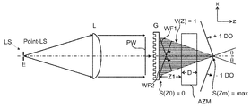
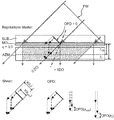
선행기술에 제시된 방법과 달리 본 발명의 실시예에 따라 체적 격자는 마스터 격자에서 회절되는 파동장의 회절 차수인 2개의 파동장의 간섭에 의해 형성될 수 있다. 회절된 파동장은 마스터 격자를 통과한 후에 간섭 콘트라스트와 중첩되고, 상기 간섭 콘트라스트는 마스터 격자와의 간격의 함수이다. 이러한 간섭 콘트라스트는 마스터 격자를 조명하는 노출광의 파동장의 간섭 특성에 의해 규정된다. 노출광의 공간적 및/또는 시간적 간섭성 함수에 의해 설명되는 이러한 특성은 광원의 특성에 의해 결정된다. 상기 특성은 광원의 스펙트럼 분포에 의존하고, 광원이 점 형태인지 또는 진폭- 및/또는 위상 격자 형태의 복속 투과 함수를 갖는 평면 비간섭성 광원인지의 여부에 의존한다. 이로 인해 선행기술과 달리 기록 매체 및 체적 격자의 측방향 확장이 실질적으로 마스터 격자의 측방향 확장과 상기 마스터 격자의 조명을 위한 광학 장치에 의해 결정된다. Unlike the methods presented in the prior art, according to an embodiment of the present invention the volume grating may be formed by the interference of two wave fields, the diffraction orders of the wave fields diffracted in the master grating. The diffracted wave field overlaps with the interference contrast after passing through the master grating, which is a function of the distance to the master grating. This interference contrast is defined by the interference characteristics of the wave field of the exposure light illuminating the master grating. This property, explained by the spatial and / or temporal coherence function of the exposure light, is determined by the property of the light source. The property depends on the spectral distribution of the light source and on whether the light source is a point or a planar incoherent light source with a bi-speed transmission function in the form of an amplitude- and / or phase grating. Thus, unlike the prior art, the lateral expansion of the recording medium and the volume grating is substantially determined by the optical device for the lateral expansion of the master grating and the illumination of the master grating.
실질적으로 시준된 또는 적어도 부분적으로 시준된 파동장을 갖는 광원에 의해 조명되는 마스터 격자 후방에 광 확산 방향으로 마스터 격자에서 회절되지 않은 파동장, 회절된 파동장 그리고 상기 마스터 격자 후방에서 퍼지는 파동장 사이의 상대적인 측방향 변위(s(z))가 제공되고, 이러한 변위는 조명하는 파동장의 미리 정해진 복소 공간적 및/또는 시간적 간섭성 함수(Γ)에 의해 서로 간섭하는 파동장의 간섭 콘트라스트(V(z))의 미리 정해진 깊이에 따른 곡선을 형성한다. Between a wave field un diffracted in the master grating, a diffracted wave field and a wave field spreading behind the master grating in the light diffusion direction behind the master grating illuminated by a light source having a substantially collimated or at least partially collimated wave field. Relative lateral displacements of s (z) are provided, the displacements of which interfere with each other by the predetermined complex spatial and / or temporal coherence function (Γ) of the illuminating wave field (V (z)). Form a curve according to a predetermined depth.
마스터 격자에서 회절되어 간섭 파면의 양의 제곱이 강도값이고, 상기 강도값은 광 확산 방향으로 마스터 격자의 후방에 배치되고 광 강도가 감도 임계값을 초과하는 감광 기록 매체의 영역에서 투과율 및/또는 굴절률의 변화를 야기하므로, 이로 인해 진폭- 및/또는 위상에 따라 효과적인 체적 격자가 얻어진다. Diffraction at the master grating so that the square of the amount of the interference wavefront is an intensity value, the intensity value being disposed behind the master grating in the light diffusion direction and the transmittance and / or in the region of the photosensitive recording medium whose light intensity exceeds the sensitivity threshold. Since it causes a change in refractive index, this results in an effective volume grating depending on amplitude- and / or phase.
그러나, 기록 매체는 상기 격자가 물리적 과정에 의해 영구적으로 확정될 수 있도록 제공되어야 한다. However, a recording medium should be provided so that the grid can be permanently determined by a physical process.
따라서 기록 매체로서 예를 들어 광중합체가 사용되고, 상기 광중합체는 광합화 공정을 야기하는 감광성 개시제를 포함한다.Thus, for example, a photopolymer is used as the recording medium, and the photopolymer includes a photosensitive initiator which causes a photosynthesis process.
또한, 바람직하게 확정되지 않고 동적으로 신속하게 변하는 아포다이즈된 격자 또는 간섭 패턴이 이용될 수 있는 실시예도 제공된다. 예를 들어 임의의 파동장, 예를 들어 초음파 파동장은 전술한 바와 같이 중첩될 수 있으므로, 아포다이즈된 초음파 간섭 패턴, 즉 초음파 격자가 형성될 수 있고, 상기 초음파 격자는 광학적으로 또는 미리 정해진 각도- 및/또는 파장 선택성을 갖는 초음파에 의해 재구성될 수 있고 신속하게 변경될 수 있다. In addition, embodiments are also provided in which an apodized grating or interference pattern may be used that is preferably not determined and is rapidly changing dynamically. For example, any wave field, for example an ultrasonic wave field, can be superimposed as described above, so that an apodized ultrasonic interference pattern, i.e., an ultrasonic grating, can be formed, which is optically or predetermined angled. And / or can be reconfigured by ultrasound with wavelength selectivity and changed quickly.
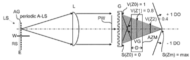
2개의 간섭 파면의 간섭 기능은, 상기 파면이 광 확산 방향으로 기록 매체 전방에 배치된 마스터 격자에서 미리 정해진 공간적 및/또는 시간적 간섭성을 갖는, 광원으로부터 방사되어 시준된 그 파동장의 회절의 상이한 회절 차수가 됨으로써 제공된다. 이로 인해 비교적 간단하게 형성된 광학 빔 경로에 의해 규정된 노출광 분포가 형성될 수 있다. The interfering function of the two interfering wavefronts is a different diffraction of the diffraction of the wave field radiated and collimated from the light source, the wavefront having a predetermined spatial and / or temporal coherence in the master grating disposed in front of the recording medium in the light diffusion direction. The order is provided. This makes it possible to form a defined exposure light distribution by means of an optical beam path formed relatively simply.
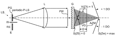
광원의 평면에 일반적인 복소 함수를 갖는 마스크 외에 통계적 스캐터러, 즉 예를 들어 회전 그라운드 글라스(ground glass)가 장착되고, 상기 그라운드 글라스는 광원의 평면에서 공간적인 분포의 위상값을 무상관화시킨다. In addition to a mask having a general complex function in the plane of the light source, a statistical scatterer, ie a rotating ground glass, is mounted, which ground correlates the phase value of the spatial distribution in the plane of the light source.
기록 매체의 특정 깊이의 간섭 콘트라스트(V(z))는 2개의 간섭 파면의 측방향 변위(s(z))(전단)에 의존하고, 상기 변위는 파동장의 확산 방향으로 좌표의 함수이다. 기록 매체의 미리 정해진 깊이 영역에 형성되는 간섭 콘트라스트(V(z))의 미리 정해진 곡선은 광원의 평면에 있는 진폭- 및/또는 위상 격자 형태의 함수이다. 측방향 변위(s(z))(전단)란 이와 관련해서 특히, 그라운드 글라스에서 비회절된 파동장들이 0차 회절 차수의 비회절 성분을 포함해서 서로 일정한 각도로 확산되고, 그라운드 글라스와의 거리(z)가 증가할수록 서로에 대해 점점 더 많이 변위되는 것을 의미한다. 이 경우 상이한 회절 차수들은 서로 상이하게 변위된다. The interference contrast V (z) of a particular depth of the recording medium depends on the lateral displacement s (z) (shear) of the two interfering wavefronts, which is a function of coordinates in the diffusion direction of the wave field. The predetermined curve of the interference contrast V (z) formed in the predetermined depth region of the recording medium is a function of amplitude- and / or phase grating form in the plane of the light source. The lateral displacement s (z) (shear) is in this connection in particular, in which the non-diffusing wave fields in the ground glass diffuse at a constant angle to each other, including the non-diffraction components of the 0th diffraction order, and the distance to the ground glass. As (z) increases, it means more and more displacement with respect to each other. In this case different diffraction orders are displaced differently from each other.
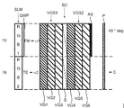
기록 매체의 미리 정해진 깊이에 제공되는 간섭 콘트라스트(V(z))에 의해 미리 정해진 굴절률- 및/또는 투과율 변조의 형태의 체적 격자가 기록 매체에 형성될 수 있고, 이러한 변조는 아포다이제이션 함수(n1(z))에 상응하고, 상기 함수는 체적 격자의 각도- 및/또는 파장 선택성을 규정하여 설정하는 것과 체적 격자의 각도- 및/또는 파장 선택성의 이차 최대치를 규정하여 억제하는 것을 가능하게 한다. 아포다이제이션 함수(n1(z))는 굴절률 변조의 포락선에 상응한다. 높은 공간 주파수로, 즉 예를 들어 1/0.5 ㎛-1로 제공되는 간섭 패턴은 이 경우 하나 또는 다수의 훨씬 더 낮은 공간 주파수, 즉 예를 들어 1/5 ㎛-1로 변조된다. A volume grating in the form of a predetermined refractive index- and / or transmittance modulation may be formed in the recording medium by means of the interference contrast V (z) provided at a predetermined depth of the recording medium, and such modulation is performed by the apodization function ( corresponding to n1 (z)), the function makes it possible to specify and set the angle- and / or wavelength selectivity of the volume grating and to suppress and suppress the secondary maximum of the angle- and / or wavelength selectivity of the volume grating. . The apodization function n1 (z) corresponds to the envelope of the refractive index modulation. The interference pattern provided at high spatial frequencies,
즉, 격자는 조명광의 특성의 적절한 선택에 의해 그 형태가 변경될 수 있으므로, 상기 격자는 방향- 및/또는 파장 선택성과 관련해서 미리 정해진 회절 특성을 갖는다. That is, the grating can be changed in shape by appropriate selection of the characteristics of the illumination light, so that the grating has predetermined diffraction characteristics with respect to the direction- and / or wavelength selectivity.
2개의 상호 간섭성 평면파에 의해 균질 기록 매체 내로 조명되는 투과 체적 격자에서 굴절률 변조의 포락선은 기록 매체 내의 흡수를 무시하면 제곱함수이다. 회절 효율의 각도- 및/또는 파장 선택성은 이러한 체적 격자의 전형적인 노광 시 싱크 함수(sinc function)의 제곱의 형태를 갖는다. The envelope of the refractive index modulation in a transmission volume grating illuminated by two mutually coherent plane waves into a homogeneous recording medium is a square function ignoring absorption in the recording medium. The angle- and / or wavelength selectivity of the diffraction efficiency takes the form of the square of the sink function during typical exposure of such volume gratings.
체적 격자의 전형적인 노광에 대한 변동 시 변경된 간섭 특성은 바람직하게, 마스터 격자를 조명하는 시준될 광원의 평면이 복소 광학 투과 함수를 가짐으로써 형성되고, 상기 투과 함수는 진폭- 및/또는 위상 격자, 진폭- 및/또는 위상 분포, 아포다이제이션 함수와 중복되는 진폭- 및/또는 위상 격자 또는 아포다이제이션 함수와 중복되는 진폭- 및/또는 위상 분포이다. The altered interference characteristic upon variation of the typical exposure of the volume grating is preferably such that the plane of the light source to be collimated illuminating the master grating has a complex optical transmission function, the transmission function being amplitude- and / or phase grating, amplitude And / or phase distribution, amplitude-and / or phase overlapping with the apodization function and / or amplitude- and / or phase distribution overlapping with the phase grating or apodization function.
각도 선택성(η(Θ)) 및/또는 파장 선택성(η(λ))에서 미리 정해진 함수 곡선이 구현되어야 하는 경우에, 광원의 평면에서 사용된 격자의 슬릿의 진폭- 및/또는 위상 함수는 이러한 함수 곡선을 제공하는 형태로, 즉 예를 들어 이러한 형태 자체로 선택되어야 한다.If a predetermined function curve is to be implemented in the angular selectivity η (Θ) and / or the wavelength selectivity η (λ), then the amplitude- and / or phase function of the slit of the grating used in the plane of the light source is It should be chosen in the form of providing a function curve, ie in this form itself.
예를 들어 굴절률 변조(n1(z))의 포락선이 제곱 함수인 경우에, 각도 선택성성(η(Θ)) 및/또는 파장 선택성(η(λ))은 싱크 함수의 제곱에 상응하는 함수 곡선을 갖는다. 이러한 함수는 제곱 함수의 푸리에 변환의 제곱값이다. For example, if the envelope of refractive index modulation n1 (z) is a square function, the angular selectivity η (Θ) and / or wavelength selectivity η (λ) is a function curve corresponding to the square of the sink function. Has This function is the square of the Fourier transform of the square function.
공간 간섭성과 간섭 패턴의 포락선이 광원의 평면에 배치된 격자의 단일 슬릿의 푸리에 변환으로부터 제공되고, 각도- 또는 파장 선택성이 또한 굴절률 변조(n1(z))의 포락선의 푸리에 변환에 비례하고, 광원의 평면 내의 개별 슬릿들의 일반적인 복소 투과 함수에 대해 자동적으로 비례하더라도, 일반적으로 맵핑(mapping)은 푸리에 변환만으로는 정확히 계산될 수 없다.The spatial coherence and the envelope of the interference pattern are provided from the Fourier transform of a single slit of the grating arranged in the plane of the light source, and the angle- or wavelength selectivity is also proportional to the Fourier transform of the envelope of the refractive index modulation n1 (z), Although the mapping is automatically proportional to the general complex transmission function of the individual slits in the plane of, in general, the mapping cannot be accurately calculated by Fourier transform alone.
예를 들어, 높은 개구수(NA), 즉 기록 매체에서 이루어지는 흡수, 제공된 기록 매체 및 제공된 기록 구조를 위해 제공된 굴절률 상승을 위한 노광량의 전달 함수에 상응하게 보정, 즉 광원의 평면에서 일반적인 복소 투과 함수의 적절한 설정이 이루어질 수 있다. 따라서 예를 들어 기록될 체적 격자의 각도- 및/또는 파장 선택성의 최적화를 위해 광원의 개별 슬릿들의 전달 함수들은 상이하게 선택될 수 있다. For example, a correction corresponding to a high numerical aperture (NA), i.e., absorption made in a recording medium, a given recording medium and a given refractive index rise for a given recording structure, that is, a complex transmission function common in the plane of the light source Appropriate setting of can be made. Thus the transfer functions of the individual slits of the light source can be chosen differently, for example for the optimization of the angle- and / or wavelength selectivity of the volume grating to be recorded.
투과- 및/또는 반사 체적 격자에서 굴절률 변조의 포락선은 예를 들어 해밍(Hamming)-윈도우 함수 또는 카이저-베셀(Kaiser-Bessel)-윈도우 함수의 가우스 정규 분포 형태로도 제공될 수 있다. 이는 각도- 및/또는 파장 선택성의 이차 최대치를 현저히 감소시킨다. The envelope of the refractive index modulation in the transmissive- and / or reflective volume grating can also be provided in the form of a Gaussian normal distribution of, for example, a Hamming-window function or a Kaiser-Bessel-window function. This significantly reduces the secondary maximum of angle- and / or wavelength selectivity.
이는 예를 들어, 상이한 재구성 형상 각도- 및/또는 파장 선택성이 밀접하게 연속하는 경우에 바람직하다. 이로 인해 재현된 물체 공간에 각도- 및/또는 파장 선택성의 이차 최대치에 따른 고스트 이미지가 형성되는 것이 방지된다. This is desirable, for example, when the different reconstruction shape angles- and / or wavelength selectivity are closely contiguous. This prevents the formation of ghost images according to the second maximum of angle- and / or wavelength selectivity in the reproduced object space.
투과- 및/또는 반사 체적 격자에서 굴절률 변조의 포락선은 의도대로 노광을 위해 사용된 파동장의 간섭성의 선택에 의해 설정될 수 있다. The envelope of the refractive index modulation in the transmissive- and / or reflective volume grating can be set by selection of the coherence of the wave field used for exposure as intended.
광원의 평면에서 사용된 복합 진폭- 및/또는 위상 격자와 마스터 격자 후방에 배치된 간섭 콘트라스트(V(z)) 사이에 하기 관계가 형성된다:The following relationship is formed between the complex amplitude-and / or phase grating used in the plane of the light source and the interference contrast V (z) disposed behind the master grating:
- 간섭 콘트라스트(V(z))의 깊이 위치는 격자 주기에 의해 결정되고, The depth position of the interference contrast V (z) is determined by the lattice period,
- 함수(V(z))의 폭은 격자 주기의 개수에 의해 결정되고, The width of the function V (z) is determined by the number of lattice periods,
- 함수(V(z))의 형태는 광원의 평면에서 사용된 진폭- 및/또는 위상 격자의 개별 격자 주기의 형태에 의해 결정된다. The shape of the function V (z) is determined by the shape of the individual grating periods of the amplitude- and / or phase gratings used in the plane of the light source.
이로 인해 미리 정해진 깊이에 형성될 수 있는 체적 격자의 각도- 및/또는 파장 선택성의 형태는 굴절률 변조(n1(z))의 미리 정해진 곡선에 의해 광 확산 방향으로 조절 가능한 것이 달성될 수 있고, 상기 곡선은 싱크-, 코사인-, 가우스-, 또는 대략적으로 제곱-함수의 제곱의 형태로 재현된다. 실제로 형성될 수 있는 아포다이제이션 함수의 함수값은 이 경우 정확히 수학적으로 설명되는 함수 곡선들에 의해 예컨대 +/-10% 범위에서 편차를 가질 수 있다. This can achieve that the form of the angle- and / or wavelength selectivity of the volume grating that can be formed at a predetermined depth can be adjusted in the light diffusion direction by a predetermined curve of the refractive index modulation n1 (z), Curves are reproduced in the form of sync-, cosine-, Gaussian, or approximately square-squared functions. The function value of the apodization function that can actually be formed can in this case be varied in the range of eg +/- 10% by the function curves described exactly mathematically.
상기 곡선은 광원의 평면에서 사용된 격자의 진폭- 및/또는 위상 곡선과 직접적으로 일치한다. The curve corresponds directly to the amplitude- and / or phase curve of the grating used in the plane of the light source.
기록 매체가 선형 전달 함수를 갖는 경우에, 굴절률 변조(n1(z))의 곡선은 체적 격자가 기록되어야 하는 영역의 간섭 콘트라스트(V(z))의 곡선에 상응한다. 기록 매체의 비선형 전달 함수의 경우에 간섭 콘트라스트(V(z))는 상응하게 변경되므로, 예를 들어 싱크 함수의 값 또는 제곱값에 상응하는 굴절률 변조(n1(z))가 얻어질 수 있다. In the case where the recording medium has a linear transfer function, the curve of the refractive index modulation n1 (z) corresponds to the curve of the interference contrast V (z) of the area where the volume grating is to be recorded. In the case of the nonlinear transfer function of the recording medium, the interference contrast V (z) is correspondingly changed, so that, for example, a refractive index modulation n1 (z) corresponding to the value or square value of the sync function can be obtained.
아포다이제이션 함수들(n1(z))의 가능한 바람직한 구현은 예를 들어 함수 sin(a(z-z0))/(a(z-z0))^(n/m)에 비례하고, 이 경우 변조는 싱크 함수의 값, 즉 제곱값 또는 n/m의 멱(n, m은 정수) 또는 sin(a(z-z0))/(a(z-z0))에 의존하고, 위상 길이는 sin(a(z-z0))/(a(z-z0))의 부호에 의존해서 선택된다. A possible preferred implementation of the apodization functions n1 (z) is for example proportional to the function sin (a (z-z0)) / (a (z-z0)) ^ (n / m), in this case Modulation depends on the value of the sink function, that is, squared or n / m 멱 (n, m is an integer) or sin (a (z-z0)) / (a (z-z0)), with phase length sin It is selected depending on the sign of (a (z-z0)) / (a (z-z0)).
이는, 싱크 함수의 제로 위치에서 굴절률의 변조는 0이 되고, 싱크 함수의 음의 값의 범위에서 유전층의 위상 길이는 싱크 함수의 양의 값의 범위에 대해 π만큼, 즉 1/2 주기 만큼 이동되어 선택되는 것을 의미한다. 이러한 바람직한 실시예는 예를 들어 투과 체적 격자, 반사 체적 격자 및 유전 층스택에 응용될 수 있다. This means that the modulation of the index of refraction at the zero position of the sink function becomes zero, and the phase length of the dielectric layer in the negative value range of the sink function shifts by π, i.e. by 1/2 period, over the range of positive values of the sink function. Means to be selected. Such a preferred embodiment can be applied, for example, to transmission volume gratings, reflective volume gratings and dielectric layer stacks.
아포다이제이션 함수(n1(z))로서 작용하는 기록 매체 내의 간섭 콘트라스트(V(z))의 포락선과 광원(LQ)의 평면에서 예를 들어 단색 장(monochromatic field) 분포의 복소값 마스킹(a(x,y)*ei φ(x,y)) 사이의 실제 맵핑은 실제 사용된 광학 시스템과 예를 들어 조명 광학계의 개구수(NA)에 의존한다. 높은 개구수(NA)의 경우에 함수(a(x,y)*ei φ(x,y), 와 n1(z))는 예를 들어 더 이상 푸리에 변환(FT)에 의해 서로 결합되지 않는다. 일반적으로 n1(z)는 기록 물질의 평면에서 위상에 있어서 비상관되지 않은 LQ의 회절 이미지에 의해 형성된다. 공간적으로 폭이 넓은 LQ의 경우에 이는 개별 스펙트럼 라인에 의한 중첩 형태로 유사하게 적용된다. Complex value masking of monochromatic field distribution, for example in the plane of the light source LQ and the envelope of the interference contrast V (z) in the recording medium serving as the apodization function n1 (z) The actual mapping between (x, y) * e i φ (x, y) ) depends on the optical system actually used and for example the numerical aperture NA of the illumination optics. In the case of a high numerical aperture NA, the functions a (x, y) * e i φ (x, y) and n1 (z) are no longer coupled to each other by, for example, a Fourier transform (FT). . In general, n1 (z) is formed by diffraction images of LQ that are not uncorrelated in phase in the plane of the recording material. In the case of spatially wide LQ, this applies similarly in the form of superposition by separate spectral lines.
체적 격자의 노광 시 사용된 아포다이제이션 함수는, 기록 매체의 깊이(z)를 따라 유효한 기록 매체의 흡수 작용, z에 의존하는 빔 비율의 변동 및 z에 의존하는 간섭 콘트라스트의 흡수에 따른 변동을 보상하도록 선택될 수 있다. The apodization function used in the exposure of the volume grating is based on the absorption action of the effective recording medium along the depth z of the recording medium, the variation of the beam ratio dependent on z and the absorption of the interference contrast dependent on z. May be selected to compensate.
미리 정해진 깊이에 형성될 수 있는 체적 격자의 각도 선택성은 형성될 관련 체적 격자의 두께에 의해 제어될 수도 있다. The angular selectivity of the volume grating, which may be formed at a predetermined depth, may be controlled by the thickness of the associated volume grating to be formed.
이는 체적 격자의 일반적인 특성이고, 광 확산 방향으로 체적 격자의 두께가 증가할수록 상기 격자에서 "유효 광"의 회절 성분의 각도 범위는 점점 작아지는 것을 의미한다. This is a general characteristic of the volume grating, which means that as the thickness of the volume grating increases in the light diffusion direction, the angular range of the diffraction component of "effective light" in the grating becomes smaller.
예를 들어 광 확산 방향으로 또는 z-좌표의 방향으로 차례로 또는 뒤섞여 배치된 2개의 체적 격자를 기록 매체 내로 임프린트 하기 위해, 기록 매체는 미리 정해진 두께를 가져야 한다. 즉, 상이한 특성의 체적 격자들은 서로 노광될 수도 있고, 예를 들어 2개의 상이한 유효광 파장을 위해 작용하는 2개의 체적 격자가 조명될 수 있다. 광 확산 방향이란 이와 관련해서 하나의 파면의 확산 방향이거나 또는 광(노출광 또는 유효광)의 중첩하는 파면들의 결과되는 확산 방향이다. In order to imprint two volume gratings arranged in the light diffusion direction or in the direction of z-coordinates one after another or in a mixture, for example, the recording medium must have a predetermined thickness. That is, the volume gratings of different characteristics may be exposed to each other, for example two volume gratings serving for two different effective light wavelengths may be illuminated. The light diffusion direction is in this connection the diffusion direction of one wavefront or the resulting diffusion direction of overlapping wavefronts of light (exposed light or effective light).
미리 정해진 깊이에 형성될 수 있는 체적 격자는 미리 정해진 광파장에 대해 설계될 수 있고, 바람직하게 상기 파장의 광에만 회절에 의해 영향을 미칠 수 있다. A volume grating that can be formed at a predetermined depth can be designed for a predetermined light wavelength, and preferably only affects light of that wavelength by diffraction.
즉, 체적 격자의 형상과 회절에 의해 격자가 반응하는 파장 길이 사이에 직접적인 관계가 있다. 이와 다른 파장은 억제되거나 또는 체적 격자에 의해 영향을 받지 않는다. That is, there is a direct relationship between the shape of the volume grating and the wavelength length at which the grating reacts by diffraction. Other wavelengths are not suppressed or affected by the volume grating.
기록 매체에서 노출광의 강도 변조의 깊이-아포다이제이션 및/또는 깊이-분리는 본 발명에 따른 방법에 의해 동적으로 조절될 수 있다. The depth-apodization and / or depth-separation of the intensity modulation of the exposure light in the recording medium can be dynamically adjusted by the method according to the invention.
이러한 가능성은, 2개의 특성이 광원의 평면에 배치된 격자의 형태에 직접적으로 의존함으로써 제공되고, 이 경우 기록 과정 동안 상기 광원의 진폭- 및/또는 위상 특성이 변경될 수 있다. 또한, 이는 주기적으로, 예를 들어 조명빔 경로에 배치된 이동되는 위상 플레이트에 의해 이루어질 수 있다. This possibility is provided by the two properties being directly dependent on the shape of the grating arranged in the plane of the light source, in which case the amplitude- and / or phase properties of the light source can be changed during the recording process. This can also be done periodically, for example by a moving phase plate disposed in the illumination beam path.
기록 매체에서 체적 격자의 굴절률 변조의 곡선은 광원의 평면에서 복소 진폭의 미리 정해진 정적 또는 동적 조절에 의해 결정될 수 있다. The curve of the refractive index modulation of the volume grating in the recording medium can be determined by predetermined static or dynamic adjustment of the complex amplitude in the plane of the light source.
바람직한 실시예에서 마스터 격자는 표면 릴리프 격자의 형태로 형성되고, 상기 격자의 면은 조명과 관련해서 체적 격자를 위한 기록 매체의 면의 부분이거나 또는 상기 표면에 상응한다. In a preferred embodiment the master grating is formed in the form of a surface relief grating, wherein the face of the grating is part of or corresponds to the face of the recording medium for the volume grating with respect to illumination.
다른 바람직한 실시예에서 마스터 격자는 체적 격자의 형태로 형성된다. 이는 예를 들어, 격자에 입사하는 광의 파장에 비해 큰 격자 주기에서 간단하게 마스터 격자 후방의 빔 경로에서 0차 및 회절된 더 높은 회절 차수만을 형성하는 장점을 제공한다. In another preferred embodiment the master grating is formed in the form of a volume grating. This offers the advantage of forming only higher and diffracted orders of
본 발명에 따른 방법의 특징은, 상기 방법에 의해 대면적 기록 매체에 체적 격자가 생성될 수 있는 것이다. 이는, 간섭 가능한 광으로 조명을 위해 필요한 마스터 격자가 표면-릴리프 격자의 형태로 실질적으로 동일한 크기로 제조될 수 있음으로써 가능해진다. 그러나, 대면적 체적 격자는 2개의 방향으로 더 작은 마스터 격자가 중복해서 연달아 배치됨으로써(타일링) 형성될 수도 있다. 이로 인해 예컨대 20"인치 이상의 대각선 스크린을 갖는 홀로그래픽 직시형 디스플레이를 위한 예를 들어 대면적 간섭성 광학 필터가 구현될 수 있다. A feature of the method according to the invention is that a volume grating can be produced on a large area recording medium by the method. This is made possible by the fact that the master gratings required for illumination with the interfering light can be made substantially the same size in the form of a surface-relief grating. However, a large area grating may be formed by stacking smaller master gratings in two directions in succession (tiling). This allows for example a large area coherent optical filter to be implemented for a holographic direct view display having a diagonal screen of at least 20 "inches.
본 발명에 따른 방법을 확장함으로써 격자의 위상에 맞는 인접 배치, 즉 격자 주기의 거의 계속적인 연속이 이루어진다. 이는, 예를 들어 회절 이미지를 이용해서 이루어질 수 있고, 상기 회절 이미지는 위상에 적절하게 구성 시 구성된 격자의 위상 시프트를 검출할 수 없게 한다. 위상에 적절하게 구성되지 않은 격자 세그먼트의 위상 시프트는 격자의 회절 이미지에서 예를 들어 선명한 다크 라인(dark line)으로서 검출될 수 있다. 이 경우 조명된 2개의 격자 세그먼트 사이의 이행 영역은 예를 들어 절반마다 균일하게 조명된다. By extending the method according to the invention, an adjacent arrangement for the phase of the grating, ie a nearly continuous continuation of the grating period, is achieved. This can be done, for example, using a diffraction image, which makes it impossible to detect the phase shift of the grating constructed when properly configured for phase. The phase shift of the grating segment not properly configured for the phase can be detected, for example, as a clear dark line in the diffraction image of the grating. In this case the transition region between the two illuminated grating segments is uniformly illuminated every half, for example.
기록 매체 내의 간섭 콘트라스트 또는 굴절률 변조의 비대칭 프로파일은, 광원의 평면에서 위상- 및/또는 진폭 분포의 비대칭이 야기됨으로써 형성될 수 있다. An asymmetric profile of interference contrast or refractive index modulation in the recording medium can be formed by causing an asymmetry of the phase- and / or amplitude distribution in the plane of the light source.
이러한 가능성은 광원의 평면에서 위상- 및/또는 진폭 분포의 직접적인 일치 및 기록 매체 내의 광 방향으로 굴절률 변조의 프로파일로부터 주어진다. 기록 매체 내의 간섭 콘트라스트 또는 굴절률 변조의 미리 정해진 비대칭 프로파일은 예를 들어 유효광의 이용과 관련한 더 높은 회절 차수를 억제하기 위해 제공될 수 있다. This possibility is given from the direct match of the phase- and / or amplitude distribution in the plane of the light source and the profile of the refractive index modulation in the light direction in the recording medium. The predetermined asymmetric profile of the interference contrast or refractive index modulation in the recording medium can be provided to suppress higher diffraction orders, for example with regard to the use of effective light.
따라서 예를 들어 광원의 평면에서 비대칭을 형성하기 위해 톱니 형상의 표면 릴리프 위상 격자가 사용될 수 있다. Thus, for example, a serrated surface relief phase grating can be used to form an asymmetry in the plane of the light source.
표면 릴리프 위상 격자에서 회절의 예컨대 0차 및 1차 회절 차수의 간섭에 대한 대안으로서 0차 및 2차 회절 차수 또는 다른 회절 차수의 간섭도 기록 매체에서 체적 격자를 형성하기 위해 이용될 수 있다. As an alternative to the interference of, for example, the 0th and 1st diffraction orders of diffraction in the surface relief phase grating, the 0th and 2nd diffraction orders or other diffraction orders of interference may also be used to form the volume grating in the recording medium.
이는 마스터 격자의 특수한 디자인에 의해 달성되고, 따라서 관련 회절 차수의 회절 효율이 최대화되고, 나머지 회절 차수의 회절 효과는 최소화된다. This is achieved by the special design of the master grating, so that the diffraction efficiency of the relevant diffraction orders is maximized, and the diffraction effects of the remaining diffraction orders are minimized.
기록 매체는 개시제를 포함할 수도 있고, 이 경우 노출광의 직류 광 성분은 기록 매체의 개시제의 활성화 또는 비활성화를 위해 이용될 수 있다. The recording medium may comprise an initiator, in which case the direct light component of the exposure light may be used for activation or deactivation of the initiator of the recording medium.
이러한 매체는 예를 들어 PTR(Photo Thermo refractive; 광열 굴절) 글래스이고, 상기 글래스에서 2개의 표면부터 UV-광으로 전노광에 의해 광 방향으로 가우스 형태의 굴절률 프로파일이 체적 격자의 기록 전에 형성될 수 있다. Such a medium is, for example, PTR (Photo Thermo refractive) glass, in which the Gaussian refractive index profile in the light direction can be formed prior to recording of the volume grating by preexposure from two surfaces to UV-light in the glass. have.
기록 매체로서 광학 또는 전기 제어 가능한 물질도 전환 가능한 체적 격자를 형성하는데 이용될 수 있다. Optical or electrically controllable materials as recording media can also be used to form switchable volume gratings.
적절한 매체는 예를 들어 LC-층이다. 이로써 체적 격자의 회절 효율은 전압에 따라서 변경될 수 있다. Suitable media are, for example, LC-layers. As a result, the diffraction efficiency of the volume grating can be changed according to the voltage.
형성될될 수 있고 또는 형성된 체적 격자에서 광의 회절에 의해 상이한 재구성 형상은(평면파/평면파, 평면파/구면파 및 기타) 확실히 설정된 및/또는 전환될 수 있는 형태로 구현될 수 있다. Different reconstructed shapes (plane waves / plane waves, plane waves / spherical waves and others) by means of diffraction of light in the formed volume gratings may be realized in a form that can be reliably set and / or switched.
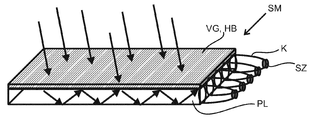
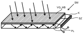
예를 들어 평면파를 수렴하는 구면파로 변환하고, 따라서 필드 렌즈의 효과를 갖는 체적 격자가 형성될 수 있다. 이러한 필드 렌즈는 예를 들어 자동 입체 디스플레이 또는 홀로그래픽 디스플레이에서 이용될 수 있다. 기록 매체에서 본 발명에 따른 방법에 의해 하나 또는 다수의 추가 체적 격자가 계속해서 광학 함수를 기록하기 위해 임프린트 또는 형성될 수 있는 경우에, 노광된 기록 매체는 다수의 광학 함수를 구현할 수 있고, 개별 소자로서 상기 디스플레이에 집적될 수 있다. For example, a volume grating can be formed that converts a plane wave into a converging spherical wave, thus having the effect of a field lens. Such field lenses can be used, for example, in autostereoscopic displays or holographic displays. In the case where one or a plurality of additional volume gratings can be imprinted or formed for continuously recording an optical function by the method according to the invention in the recording medium, the exposed recording medium can implement a plurality of optical functions, and the individual It can be integrated into the display as an element.
기록 매체에서 체적 격자의 기록 시 반사는 조명광의 공간적 및/또는 시간적 간섭성 특성의 미리 정해진 선택에 의해 억제될 수 있다. 즉, 이로써 기록 시 반사는 저지되는 것이 아니라, 반사된 성분들이 상기 조치에 의해 반사되지 않은 성분을 더 이상 구조적으로 간섭할 수 없으므로, 이로 인해 기록 매체의 노광을 위한 감도 임계값이 초과되지 않는다. Reflection in the recording of the volume grating in the recording medium can be suppressed by a predetermined selection of the spatial and / or temporal coherence characteristics of the illumination light. That is, the reflection is not prevented during recording, but since the reflected components can no longer structurally interfere with the components not reflected by the above measures, this does not exceed the sensitivity threshold for exposure of the recording medium.
기록 매체의 미리 정해진 깊이에 미리 정해진 형태와 두께를 갖는 체적 격자의 기록은 경계면부터 기록 매체의 개시제의 화학적 또는 광학적 감소(depletion)에 의해 이루어질 수 있다. Recording of a volume grating having a predetermined shape and thickness at a predetermined depth of the recording medium can be made by chemical or optical depletion of the initiator of the recording medium from the interface.
본 발명에 따른 방법과 달리, 이러한 방법은 그렇게 유연하지 않은데, 그 이유는 예를 들어 화학적 감소는 기록 매체의 경계면 또는 표면에서부터만 도입될 수 있기 때문이다. 따라서 이러한 방법은 일반적으로, 즉 이 실시예에서 기록 매체의 경계면에 직접 인접한 단일 격자의 기록만을 가능하게 한다. Unlike the method according to the invention, this method is not so flexible because, for example, chemical reduction can only be introduced from the interface or surface of the recording medium. Thus, this method generally only allows recording of a single grating directly adjacent to the interface of the recording medium in this embodiment.
기록 매체 내의 개시제의 광학적 감소의 확장은 예를 들어 광 조명에 의해서도 이루어질 수 있고, 상기 광은 예를 들어 기록 매체의 중앙에 놓인 층에 간섭성이 존재하지 않거나 또는 약간의 간섭성만이 제공되도록, 즉 약간의 간섭 콘트라스트(V(z))만이 제공되도록 변조된 공간적 간섭성을 갖는다. 활성화 에너지를 필요로 하는 광중합체가 제공되기 때문에, 조명광의 직류 광 성분에 대해 국부적으로 예를 들어 팩터 4만큼 증가한 강도가 이용될 수 있으므로, 상기 층에서 국부적으로 개시제가 감소될 수 있다. 노출광의 가능한 통계적 위상 변이가 도입되면, 기록 매체 내로 격자 구조가 임프린트되지 않지만, 개시제 농도는 감소한다. 기록 매체의 예컨대 평균 깊이 영역에서 체적 격자를 노광하기 위해 이용될 수 있는 개시제 농도는 유지된다. The expansion of the optical reduction of the initiator in the recording medium can also be made by, for example, light illumination, such that the light is provided with no coherence or only slight coherence, for example in the central layer of the recording medium, That is, spatial coherence modulated such that only a slight interference contrast V (z) is provided. Since photopolymers are required that require activation energy, an increased intensity, for example by factor 4, can be used locally for the direct light component of the illumination light, so that the initiator can be reduced locally in the layer. If a possible statistical phase shift of the exposure light is introduced, the lattice structure is not imprinted into the recording medium, but the initiator concentration is reduced. An initiator concentration that can be used to expose the volume grating in the average depth region of the recording medium, for example, is maintained.
이러한 체적 격자는 기록 매체의 두께보다 훨씬 작은 유효 층 두께를 갖는다. 이러한 방법은 예를 들어 더 높은 회절 차수를 갖지 않는 미리 정해진 각도- 및/또는 파장 선택성을 형성하기 위해 이용될 수 있다. This volume grating has an effective layer thickness much smaller than that of the recording medium. This method can be used, for example, to form predetermined angle- and / or wavelength selectivity that do not have a higher diffraction order.
기록 매체의 층 두께의 부분으로 체적 격자의 두께를 제한하는 다른 가능성은 광원의 공간적 분포(I(λ)), 즉 시간적 간섭성에 의해 주어진다. Another possibility of limiting the thickness of the volume grating as part of the layer thickness of the recording medium is given by the spatial distribution I (λ) of the light source, i.e. temporal coherence.
공간적 간섭성(![]()
![]()
물론, 이러한 그리고 다른, 예를 들어 공간적인 간섭성(![]()
![]()
백색광 마이컬슨 간섭계로부터 공지된 바와 같이, 백색광의 스펙트럼 폭이 큰 경우, 2개의 간섭계 암의 광학 거리는 상기 암의 길이가 3 ㎛보다 작게 조정될 때에만, 즉 경로 길이 차(OPD;optical path difference)가 ≤ 3 ㎛일 때에만, 예를 들어 간섭 가능성이 제공된다. As is known from the white light Michelson interferometer, when the spectral width of the white light is large, the optical distance of the two interferometer arms is only when the length of the arms is adjusted smaller than 3 μm, i.e., the optical path difference (OPD) Only when ≦ 3 μm, for example, the possibility of interference is provided.
간섭 파면들 중 하나의 파면이 간섭하는 다른 파면에 대해 틸팅되고, 2개의 경로의 경로 길이 차가 조정되는 경우에, 백색광 간섭계에서 간섭 콘트라스트는 최대치를 갖고, 간섭 콘트라스트는 측면에서 커트라인 OPD =0만큼 감소하고, 즉 OPD가 증가할수록 틸팅이 커진다. 이는, 틸팅이 국부적인 OPD의 변경에 상응하기 때문이다. 이는 예를 들어 광원의 파워 스펙트럼 밀도(S(λ))를 결정하기 위해 이용되는데, 그 이유는 이는 발진 신호 성분의 푸리에 변환으로 인해 형성되기 때문이다. If one of the interfering wavefronts is tilted with respect to the interfering other wavefront, and the path length difference of the two paths is adjusted, the interference contrast in the white light interferometer has a maximum, and the interference contrast decreases in the side by cutoff OPD = 0. That is, as the OPD increases, the tilting increases. This is because the tilting corresponds to a change in the local OPD. This is used, for example, to determine the power spectral density (S (λ)) of the light source, because it is formed due to the Fourier transform of the oscillating signal component.
또한, 이는 예를 들어 DOE에 의한 노광 시 이용되고 예를 들어 기록 매체에서 그와 달리 충분한 스펙트럼 광대역 방사를 이용하여 이루어지는 체적 격자 형태로 기록되는 종래의 2-빔 간섭에서, z-방향을 따른 아포다이제이션이 도입될 수 있고, 상기 아포다이제이션은 x-y 평면으로도 도입되는 것을 의미한다. 다시 말해서 이는, 깊이를 따라, 즉 z-방향으로 충분히 높은 간섭 콘트라스트(V(z))에서 예를 들어 10 ㎛로 제한되어야 하고 충분한 스펙트럼 광대역으로 구현되는 종래의 2-빔 간섭은 예를 들어 60°의 2개의 파면의 상대적인 틸팅 하에, 간섭 패턴이 측방향으로 및 틸팅의 축에 대해 수직으로 약 ±6 ㎛의 폭으로 제한되도록 실시된다. 따라서 이러한 방법은 측방향 폭이 더 작은 체적 격자에서만 이용될 수 있다. 그러나 본 발명에 따른 목표는 예컨대 20인치 스크린을 위한 디스플레이 크기의 체적 격자를 형성하는 것이다. It is also used for exposure by DOE, for example in conventional two-beam interference, recorded in the form of a volume grating made for example using otherwise sufficient spectral broadband radiation in the recording medium, the apophores along the z-direction. Digestion may be introduced, which means that the apodization is also introduced into the xy plane. In other words, this should be limited to, for example, 10 μm at a sufficiently high interference contrast (V (z) along the depth, ie in the z-direction, and a conventional two-beam interference implemented with sufficient spectral broadband is for example 60 Under the relative tilting of the two wavefronts of °, the interference pattern is implemented to be limited to a width of about ± 6 μm laterally and perpendicular to the axis of tilt. Thus this method can only be used in volume gratings with smaller lateral widths. However, the goal according to the invention is to form a display grid of volume, for example for a 20 inch screen.
충분히 높은 간섭 기능의 영역의 측방향 폭은 - 조명에 이용되는 방사의 스펙트럼 대역이 큰 경우에도 - 현저히 확장될 수 있다. The lateral width of the region of sufficiently high interference function can be significantly expanded-even if the spectral band of the radiation used for illumination is large.
높은 간섭 콘트라스트를 갖는 영역의 측방향 폭을 증가시키기 위해 그리고 깊이를 따라, 즉 z-방향으로 높은 간섭 콘트라스트(V(z))를 갖는 영역의 작은 폭을 달성하기 위해, 작은 시간적 간섭성의 방사로 간섭 패턴을 형성하는데 적합한 적어도 2개의 가능성 또는 모든 가능성이 제공된다. In order to increase the lateral width of the region with high interference contrast and to achieve a small width of the region with high interference contrast V (z) along the depth, i.e. in the z-direction, At least two or all possibilities are provided that are suitable for forming the interference pattern.
입사하는 파면과 파면이 반사되는 거울로 반사 홀로그램을 형성하는 것은 ㅁ매우 간단할 수 있고, 이 경우 거울은 기록 매체의 층에 대해 가능한 한 가깝게 배치되어야 한다. 간행물 US 7,792,003 B2호에는 이러한 방법이 기술되어 있다. 간섭 패턴의 형성되는 포락선 및 굴절률 변조(n1(z))의 아포다이제이션 함수는 싱크 함수의 절반에 비례한다. US 7,792,003 B2호에는, 조합된 격자의 대략 사각형 파장 선택성을 얻기 위해, 싱크 형태의 굴절률 변조의 각 절반만, 즉 싱크 형태의 간섭 콘트라스트의 절반만 기록되는 반사 홀로그램과 2개의 반사 홀로그램을 조합하는 것을 필요로 하는 것이 제시되어 있다(US 7,792,003B2, 도 5A-5D 참조). Forming a reflective hologram with the incident wavefront and the mirror on which the wavefront is reflected can be very simple, in which case the mirror should be placed as close as possible to the layer of recording medium. Publication US 7,792,003 B2 describes this method. The apodization function of the envelope and refractive index modulation n1 (z) formed of the interference pattern is proportional to half of the sink function. US 7,792,003 B2 combines two reflective holograms with a reflective hologram in which only half of the sync-type refractive index modulation, i.e., only half of the sync-shaped interference contrast, is recorded to obtain approximately square wavelength selectivity of the combined grating. What is needed is shown (see US 7,792,003B2, FIGS. 5A-5D).
거울의 사용은 2개의 간섭 파면 사이의 각도가 큰 경우에도 간섭 콘트라스트의 비교적 큰 측방향 폭을 형성할 수 있게 하고, 상기 폭은 거울에 직접 제공되거나 또는 예를 들어 반사하는 캐리어 박막에 배치된 기록 매체에서 미리 정해진 크기의 측방향 폭을 취할 수 있다. 이는 반사 면에서 간섭 파면 사이의 OPD가 항상 0이라는 것에 근거한다. 깊이를 따라, 즉 z-방향으로 입사하는 파면과 반사되는 파면 사이의 OPD가 현저히 증가할수록, 입사 및 반사각은 커진다. 다시 말해서, US 7,792,003 B2 호에 기술된 방법에 대해 매우 제한된 간섭 콘트라스트(V(z))의 길이방향 분포 함수의 선택만이 이루어질 수 있다. 또한, 재구성 형상은 반사 면에 대해 평행한 브래그(Bragg)-격자 평면으로 제한되는데, 그 이유는 간섭 파면의 입사각과 반사각은 동일하기 때문이다. The use of a mirror makes it possible to form a relatively large lateral width of the interference contrast even when the angle between the two interfering wavefronts is large, the width being provided directly to the mirror or arranged for example on a reflecting carrier film The media can take a lateral width of a predetermined size. This is based on the fact that the OPD between the interfering wavefronts in the reflection plane is always zero. As the OPD increases significantly along the depth, i.e., between the incident and reflected wavefronts in the z-direction, the incident and reflected angles become larger. In other words, only a very limited selection of the longitudinal distribution function of the interference contrast V (z) can be made for the method described in US 7,792,003 B2. In addition, the reconstruction shape is limited to the Bragg-lattice plane parallel to the reflective plane, since the incident angle and the reflective angle of the interference wavefront are the same.
US 7,792,003 B2에 따른 제한을 현저히 줄이는 여러 가능성들이 있다. 하나의 가능성은 광원의 파워 스펙트럼 밀도(S(λ))의 주기성을 이용하는 것이다. 이는, 시간적 간섭성에서 주기성, 즉 사전 설정 가능하게 조절될 수 있는 주기와 곡선을 갖는 비트를 야기한다. 이것은 비너-킨친(Wiener-Khinchin) 정리에 근거한다. 따라서, 예를 들어 거울 표면에 직접 적용되는 간섭 콘트라스트의 절반 싱크 함수가 바로 기록되는 것이 아니라 비트의 후속 부분, 즉 예컨대 전체 싱크 함수가 기록되도록 예를 들어 거울과 기록 매체 사이의 거리가 사전 설정 가능하게 선택될 수 있다. 비트의 형성을 위해 예를 들어 광원의 2개의 약간 분리된 스펙트럼 영역이 이용된다. 이는 프로세스 단계를 감소시키고, 예를 들어 2개의 절반 싱크 함수의 기록 시 필요할 수 있는 2개의 체적 격자를 위상에 적절하게, 즉 모듈로(modulo) 2π 위상 시프트를 사용하지 않고 구성하는 복잡성을 방지한다.There are several possibilities for significantly reducing the limits in accordance with US 7,792,003 B2. One possibility is to use the periodicity of the power spectral density S (λ) of the light source. This leads to periodicity in temporal coherence, i.e., bits with periods and curves that can be preset adjustable. This is based on the Wiener-Khinchin theorem. Thus, for example, the distance between the mirror and the recording medium can be preset so that, for example, the half sync function of the interference contrast applied directly to the mirror surface is not recorded directly, but the subsequent part of the bit, i.e. the entire sync function, is recorded. Can be chosen. Two slightly separated spectral regions of the light source are used for the formation of the bits, for example. This reduces the process steps and avoids the complexity of configuring two volume gratings, which may be required for the writing of two half sync functions, for phase, ie without using a modulo 2π phase shift. .
기록 매체에서 굴절률 분포(n1(z))의 깊이 아포다이제이션은 시간적 간섭성의 비트 함수(beat function)를 이용하여 가능하다. 비트 주파수는 광원의 적어도 약간 분리된 사용된 스펙트럼 영역의 간격에 의해 - 예를 들어 2개, 일반적으로 그 이상 - 결정된다. 비트의 포락선의 곡선은 광원의 스펙트럼 분포의 섹션의 형태에 의해 결정된다. 굴절률 분포(n1(z))의 깊이 아포다이제이션의 곡선을 결정하기 위해, 즉 미리 결정하여 설정할 수 있기 위해, 예를 들어 상기 섹션을 위해 약간 분리된 2개의 구형 함수 외에 약간 분리된 2개의 가우스 함수도 이용될 수 있다.Depth apodization of the refractive index distribution n 1 (z) in the recording medium is possible using a beat function of temporal coherence. The bit frequency is determined by the spacing of the used spectral regions at least slightly separated of the light source-for example two, generally more. The curve of the envelope of the bit is determined by the shape of the section of the spectral distribution of the light source. To determine the curve of the depth apodization of the refractive index distribution n1 (z), i.e., to be able to set it in advance, for example, two slightly separated Gaussian in addition to two slightly separated spherical functions for the section. Functions can also be used.
다른 가능성은 기록을 위해 사용된, 예를 들어 반사 홀로그램에 의해 형성될 수 있는 파면의 방향에 따른 반사를 이용함으로써 제공된다. 이는 예를 들어 표면 릴리프- 또는 체적 격자일 수 있고, 상기 격자는 각각 예를 들어 하나의 회절 차수의 최대 반사에 대해 설계된다. 그러나 반사 액정 격자가 이용될 수도 있고, 이는 매우 유연한 노광 구조를 제공한다. 따라서 입사각을 반사각과 동일하게 제한하는 것은 생략될 수 있다. 이로써 형성된 체적 격자의 재구성 형상은 반사하는 면에 대해 평행한 브래그(Bragg)-격자 평면에 제한되지 않는다. Another possibility is provided by using reflection along the direction of the wavefront used for writing, for example, which can be formed by a reflective hologram. It may for example be a surface relief- or volume grating, each grating designed for maximum reflection of one diffraction order, for example. However, a reflective liquid crystal grating may be used, which provides a very flexible exposure structure. Therefore, limiting the incident angle equal to the reflection angle can be omitted. The reconstruction shape of the volume grating thus formed is not limited to the Bragg-lattice plane parallel to the reflecting face.
입사각과 동일한 반사각을 갖는 반사 체적 격자의 간단하고 디자인 자유도를 매우 제한하는 재구성 형상으로부터 이러한 제한을 제거함으로써 재구성 형상-파라미터 범위는 반사-체적 격자에 의해 포함될 수 있고, 이 경우 기록된 체적 격자의 두께는 기록 매체의 두께의 일부로 제한, 기록 매체 내에서 규정된 z-평면의 선택 및 굴절률 분포(n1(z))의 깊이 아포다이제이션의 규정된 곡선의 선택은 조명광의 시간적 간섭성 특성의 이용에 의해서도 가능해진다. By eliminating this limitation from the reconstruction shape which greatly limits the design freedom of the reflective volume grating having the same angle of incidence as the angle of incidence, the reconstruction shape-parameter range can be covered by the reflective volume grating, in which case the thickness of the recorded volume grating Is limited to a part of the thickness of the recording medium, the selection of the defined z-plane within the recording medium and the selection of the prescribed curve of the depth apodization of the refractive index distribution (n1 (z)) depends on the use of the temporal coherent properties of the illumination light. It is also possible.
하나의 복합 파동장을 다른 복소 파동장으로 다수의 변환은, 예를 들어 온-축-평면파를 오프-축-평면파로 변환하는 제 1 투과 체적 격자 및 오프-축-평면파를 온-축-구형파로 변환하는 제 2 투과 체적 격자를 포함하는 온-축 작용 결합된 필드 렌즈의 구현처럼 평판 홀로그래픽 3D-디스플레이의 샌드위치-디자인에서 투과 격자로서 양호하게, 즉 반사-체적 격자의 경우보다 양호하게 실행될 수 있다. 기록 물질 또는 기록 매체의 두께의 일부로 체적 격자의 두께의 제한, 기록 매체 내에서 규정된 z-평면의 선택 및 굴절률 분포(n1(z))의 깊이 아포다이제이션의 규정된 곡선의 선택을 가능하게 하는 투과 체적 격자의 구현은 따라서 반사-체적 격자에 비해 바람직하다. A number of transformations from one compound wave field to another complex wave field, for example, convert the on-axis-plane wave to off-axis-plane wave and the on-axis-square wave to off-axis-plane wave. The sandwich-design of a flat plate holographic 3D-display, like the implementation of an on-axis action-coupled field lens comprising a second transmissive volume grating that converts to, performs better as a transmissive grating, i.e. better than the reflection-volume grating. Can be. Limitation of the thickness of the volume grating as part of the thickness of the recording material or recording medium, selection of a defined z-plane within the recording medium and selection of a prescribed curve of depth apodization of the refractive index distribution n1 (z) The implementation of a transmissive volume grating is thus preferred over the reflecting-volume grating.
투과 체적 격자는 마스터 격자를 이용해서 간단하게 재현될 수도 있다. 이는 예를 들어 DOE, 블레이즈 격자, 이진 위상 격자, 다단 위상 격자, sub-1-위상 격자와 같은 표면 릴리프 격자일 수 있고, 상기 격자들은 예를 들어 가변 듀티 사이클 및 고정적인 웨이브 폭 또는 고정적인 트랜치 폭에 의해 구현된다. 예를 들어 다층 어셈블리로서 각도 세트를 가동시킬 수 있는 PDLCG(polarization dependent liquid crystal grating; 편광 의존성 액정 격자) 또는 WO 2010/149587 호에 기술된, 계속해서 변하는 회절 각도를 형성할 수 있는 LCG와 같이 예를 들어 제어 가능한 격자는 유연한 형상에 적합하고, 이 경우 회절 효율(BWG)은 예를 들어 대략 0.5이고, 바람직하게 2개의 회절 차수만이 제공된다. The transmission volume grating may be simply reproduced using the master grating. It may be a surface relief grating such as, for example, a DOE, a blaze grating, a binary phase grating, a multistage phase grating, a sub-1-phase grating, which gratings are for example variable duty cycles and fixed wave widths or fixed trenches. Is implemented by the width. For example, a polarization dependent liquid crystal grating (PDLCG) that can drive a set of angles as a multilayer assembly, or an LCG that can form a continuously varying diffraction angle, as described in WO 2010/149587. For example, a controllable grating is suitable for a flexible shape, in which case the diffraction efficiency (BWG) is for example approximately 0.5, preferably only two diffraction orders are provided.
체적 격자는 예를 들어 마스터 격자로서 리플리케이션(replicatin)을 위해 이용될 수 있다. 전달될 2-빔 간섭 패턴의 경우에 체적 격자는 간단하게 회절 효율(BWG)에 대해 설계될 수 있고, 상기 회절 효율은 기록 매체에서 충분한 간섭 콘트라스트를 가능하게 한다. 마스터 체적 격자의 BWG는 예를 들어 η= 0.4 내지 η= 0.6의 값으로 설계될 수 있다.The volume grating can be used for replication as a master grating, for example. In the case of a two-beam interference pattern to be transmitted, the volume grating can simply be designed for diffraction efficiency (BWG), which allows sufficient interference contrast in the recording medium. The BWG of the master volume grating can be designed, for example, with a value of η = 0.4 to η = 0.6.
예를 들어 0차 및 1차 회절 차수의 파면을 위한 리플리케이션의 마스터 격자(G) 후방에서 2개의 파라미터, 측방향 변위(S(z))의 크기와 길이방향 변위(OPD(z))의 크기는 간격(z)에 따라서 변경되고, 상기 2개의 파라미터는 기록 매체에서 굴절률 분포(n1(z))의 소정의 깊이 아포다이제이션을 실시하기 위해 이용될 수 있다. Two parameters, the magnitude of the lateral displacement S (z) and the magnitude of the longitudinal displacement OPD (z), for example, behind the master grating G of the replication for wavefronts of the 0th and 1st diffraction orders. Is changed in accordance with the interval z, and the two parameters can be used to perform a predetermined depth apodization of the refractive index distribution n1 (z) in the recording medium.
실제 노광 구조의 요구를 충족하는데 적합한 길이방향 변위(OPD(z))의 크기에 의존하는 간섭 콘트라스트를 얻기 위해, 실제로 이에 맞춰진 분광 필터가 사용되어야 한다. 분광 필터로서 예를 들어 금속-간섭-필터(MIF), 반사 또는 투과 유전 층스택, 고정적 또는 가변적 페브리 페로(Fabry-Perot) 간섭 필터, 반사 또는 투과 체적 격자 및 예를 들어 변형된 분광기가 이용될 수도 있다. In order to obtain an interference contrast that depends on the magnitude of the longitudinal displacement OPD (z) that is suitable to meet the needs of the actual exposure structure, a spectrally tailored filter must be used in practice. As spectroscopic filters, for example, metal-interfering-filters (MIF), reflective or transmissive dielectric layer stacks, fixed or variable Fabry-Perot interference filters, reflective or transmissive volume gratings, and for example modified spectroscopy are used. May be
매우 유연한 분광 필터는 예를 들어 다음과 같이 구현될 수 있다. 광원의 광을 스펙트럼 분리되도록 확대하기 위해, 격자 분광계가 사용된다. 이는, 예를 들어 100 nm, 10 nm 또는 1nm의 스펙트럼 범위가 스펙트럼에 의해 타깃 평면에서 10 mm의 폭으로 분리됨으로써, 즉 세분됨으로써 이루어진다. 분광계에서 상기 평면은 일반적으로 광 검출기가 설치되는 평면이고, 상기 광 검출기는 스펙트럼 분포에 상응하는 강도 분포를 기록한다. 상기 평면에 고정, 또는 가변 강도 필터가 설치될 수 있다. 예를 들어, 스펙트럼 범위, 파워 스펙트럼 밀도(S(λ))를 의도대로 변조하기 위해, SLM, 즉, DMD(digital micromirror device)가 이용될 수 있다. 또한, 실제 펄스 형성으로부터 - 짧은 레이저 펄스의 형성을 의미함 - 스펙트럼으로 할당된 위상-SLM을 이용하는 것이 공지되어 있다. 일반적으로 광원의 스펙트럼으로 세분된 광은 복소 SLM을 조명한다. A very flexible spectroscopic filter can be implemented, for example, as follows. To enlarge the light of the light source to be spectral separated, a grating spectrometer is used. This is achieved, for example, by the spectral range of 100 nm, 10 nm or 1 nm being separated, ie subdivided, by a spectrum into a width of 10 mm in the target plane. In the spectrometer, the plane is generally the plane in which the light detector is installed, and the light detector records the intensity distribution corresponding to the spectral distribution. A fixed or variable strength filter may be installed in the plane. For example, in order to modulate the spectral range, power spectral density S (λ) as intended, an SLM, ie, a digital micromirror device (DMD), may be used. It is also known to use phase-SLMs that are allocated spectra from actual pulse formation-meaning the formation of short laser pulses. In general, light subdivided into the spectrum of the light source illuminates the complex SLM.
조절 가능한 깊이 아포다이제이션으로 반사 체적 격자의 형성의 설명에서와 유사하게 마스터와 기록 매체의 층 사이의 간격은 충분히 크게 선택될 수 있으므로, 절반 싱크- 또는 가우스 함수가 방지될 수 있고, 대칭 아포다이제이션 함수를 노광하기 위해 의도대로 제 2 또는 다른 비트 섹션이 이용될 수 있다. 조명광의 스펙트럼 섹션의 선택에 의해 예를 들어 대칭 아포다이제이션 함수가 존재하는 2개의 영역 사이에 예를 들어 노광 시간이 적절할 때 항상 기록 매체의 활성화 에너지보다 낮은 상당히 작은 간섭 콘트라스트(V(z))가 존재하는 충분히 큰 영역을 형성하는 것도 가능하다. 따라서, 예를 들어 상이한 깊이 평면에 있는, 예를 들어 z-폭으로 각각 10 ㎛로 제한된 개별 체적 격자들을 연속해서 100 ㎛ 두께의 기록 매체 내로 노광시키는 것도 가능하다. Similar to the description of the formation of the reflective volume grating with adjustable depth apodization, the spacing between the layers of the master and the recording medium can be chosen sufficiently large, so that half sink- or Gaussian function can be avoided, and the symmetrical apodoid A second or other bit section can be used as intended to expose the transition function. By the selection of the spectral section of the illumination light, for example, between the two regions where a symmetric apodization function is present, for example, a significantly smaller interference contrast (V (z)) which is always lower than the activation energy of the recording medium when the exposure time is appropriate, for example. It is also possible to form a sufficiently large area in which is present. Thus, it is also possible to expose the individual volume gratings, for example in a different depth plane, for example, z-width, each limited to 10 μm, continuously into a 100 μm thick recording medium.
깊이에 따라 분리된 및-/또는 아포다이즈된 체적 격자를 형성하기 위한 공간적 간섭성(![]()
![]()
전술한 방법의 가능한 응용예는 빔 컴바이너이고, 상기 빔 컴바이너는 미리 정해진 두께의 적어도 2개의 체적 격자를 가진 기록 매체를 포함하고, 광 변조기의 픽셀로부터 방사되는 광의 중첩에 이용된다. 이러한 빔 컴바이너는 예를 들어 대형 스크린 크기를 갖는 홀로그래픽 직시형 디스플레이의 구현을 위한 주요 부품이다. 이러한 빔 컴바이너의 작동 원리와 이용 방법은 예를 들어 WO 2010/149588호에 기술되어 있으므로, 홀로그래픽 직시형 디스플레이에서 이러한 빔 컴바이너를 이용하기 위해 상기 간행물에 제시된 실시예가 구현될 수 있다. 이와 관련해서 WO 2010/149588 A1호가 참조된다. A possible application of the above method is a beam combiner, which comprises a recording medium having at least two volume gratings of a predetermined thickness and is used for superimposing light emitted from the pixels of the light modulator. Such beam combiners are a major component for the implementation of holographic direct view displays with large screen sizes, for example. Since the principle of operation and the method of use of such a beam combiner are described, for example, in WO 2010/149588, the embodiment presented in the above publication can be implemented for using such a beam combiner in a holographic direct view display. In this regard reference is made to WO 2010/149588 A1.
전술한 방식으로 형성된 체적 격자는 이 경우 폭과 선택적으로는 연장부에서 미리 정해진 각도 선택성을 갖는다. 이는 특히, 예를 들어 직시형 디스플레이에서 이용 시 더 높은 회절 차수를 억제하고 결정된 회절 차수의 광만을 관찰자의 눈에 도달시키기 위해 필요하다. The volume grating formed in the manner described above has in this case a predetermined angle selectivity in width and optionally in extension. This is particularly necessary for suppressing higher diffraction orders and for reaching only the eyes of the determined diffraction orders, for example when used in direct view displays.
빔 컴바이너의 실제 형상은 예를 들어 각각 미리 정해진 두께를 갖는 6개의 체적 격자와 미리 정해진 다른 두께를 갖는 중간층의 층 스택을 포함한다. 이는 예를 들어 WO 2010/149588 A1호의 도 6 내지 도 8 및 도 10에 도시되고, 이 경우 상기 간행물에 제시된 체적 격자(Vg1, Vg2, Vg3 및 Vg4)는 기록 매체에 임프린트 될 수 있다. The actual shape of the beam combiner includes, for example, six volume gratings each having a predetermined thickness and a layer stack of intermediate layers having a predetermined different thickness. This is shown, for example, in FIGS. 6 to 8 and 10 of WO 2010/149588 A1, in which case the volume gratings Vg1, Vg2, Vg3 and Vg4 presented in this publication can be imprinted on the recording medium.
이러한 배치에 의해 예를 들어 광 변조기의 RGB-픽셀로부터 방사되는 광 빔들은 하나의 광 빔으로 수렴될 수 있고, 이는 WO 2010/149588 A1호에 기술된 바와 같이, 예를 들어 위상 변조기에서 복소값의 2-위상 코딩 시 필요하다. By this arrangement the light beams emitted for example from the RGB-pixels of the light modulator can converge to one light beam, which is complex valued in a phase modulator, for example, as described in WO 2010/149588 A1. Required for 2-phase coding of.
광 방향으로 빔 컴바이너에 후속하는 조리개 영역이 제공되는 경우에, 체적 격자 스택의 전체 두께는 미리 정해진 값을 초과해서는 안 된다. In the case where an aperture region subsequent to the beam combiner in the light direction is provided, the total thickness of the volume grating stack should not exceed a predetermined value.
그렇지 않을 경우 광 손실이 야기될 수 있는데, 그 이유는 빔 컴바이너로부터 방사되는 광 빔들은 발산하고 이로써 부분적으로 조리개 영역에 의해 사라지기 때문이다. Otherwise, light loss can be caused, because the light beams emitted from the beam combiner diverge and are therefore partially lost by the aperture region.
체적 격자 및 상기 체적 격자에 중첩된 아포다이제션 함수의 적절한 형성에 의해 이로써 모든 삼원색(RGB) 및 빔 컴바이너의 6개의 모든 체적 격자에 대해 < 0.1°의 재구성 형상의 각도 오차가 유지될 수 있고, 상기 각도 오차는 홀로그래픽 디스플레이에서 이러한 광학 소자들의 이용에 특히 중요하다. By proper formation of the volume grating and the apodization function superimposed on the volume grating, an angular error of <0.1 ° reconstruction shape can be maintained for all three primary colors (RGB) and all six volume gratings of the beam combiner. And the angular error is particularly important for the use of such optical elements in holographic displays.
전술한 방법의 다른 가능한 응용예는 홀로그램 부품과 태양광을 전류로 변환하는 에너지 변환 장치를 포함하는 태양광 모듈에 관한 것으로, 이 경우 홀로그램 부품은 기록 매체와 적어도 2개의 체적 격자를 포함하고, 홀로그램 부품은, 태양광이 다양한 방향에서 태양광 모듈로 입사하는 경우에, 태양광이 에너지 변환 장치를 향해 안내될 수 있도록 형성되고 태양광 모듈에 배치된다. Another possible application of the above method relates to a solar module comprising a hologram component and an energy conversion device for converting sunlight into a current, in which case the hologram component comprises a recording medium and at least two volume gratings, The component is formed and disposed in the solar module so that when sunlight enters the solar module in various directions, the sunlight can be directed towards the energy conversion device.
각각의 체적 격자를 가진 상하로 배치된 다수의 기록 매체로 이루어진 체적 격자 스택은 공지된 바와 같이 태양광 모듈의 효율을 높이기 위한 입사하는 태양광의 각도- 및/또는 파장 스펙트럼의 변조를 위해 태양 전지와 함께 이용된다. 상이한 스펙트럼 감도에 의해 태양 전지를 향해 2개의 상이한 방향으로 단파 및 장파 영역을 편향하는 상하로 배치된 2개의 체적 격자를 포함하는 태양광 모듈은 예를 들어 간행물 "Analysis and design of holographic solar concentrators"(Kostuk 외 저, Proc.SPIE, 2008, vol. 7043, pp.704301-704301-8)에 기술되어 있다. 적층에 의해 다수의 개별 체적 격자들로 상기와 같은 층 스택의 제조 시 개별 층들의 위치 설정 정확도와 관련해서 문제가 된다. The volumetric grating stack, consisting of a plurality of recording media arranged up and down with each volume grating, as known is used in conjunction with the solar cell for modulation of the angle-and / or wavelength spectrum of the incident sunlight to increase the efficiency of the solar module. Used together. A solar module comprising two volume gratings arranged up and down, which deflects short and long wave regions in two different directions towards the solar cell by different spectral sensitivity, for example, the publication "Analysis and design of holographic solar concentrators" ( Kostuk et al., Proc. SPIE, 2008, vol. 7043, pp.704301-704301-8. Lamination causes problems with the positioning accuracy of the individual layers in the manufacture of such a layer stack with a plurality of individual volume gratings.
본 발명에 따른 방법의 주요 장점은, 다중 홀로그램으로서 홀로그램 부품은 연속하는 또는 하나의 기록 매체에 각각 미리 정해진 두께를 가진 다수의 체적 격자의 스택으로서 형성될 수 있다는 것이다. The main advantage of the method according to the invention is that the hologram component as multiple holograms can be formed as a stack of multiple volume gratings each having a predetermined thickness on successive or one recording medium.
태양광의 집광 및 전기 에너지로 변환 시 가능한 한 높은 효율의 요구에 상응하게 홀로그램 부품의 층 구조는 적어도 하나의 미리 정해진 각도 선택성 및/또는 적어도 하나의 미리 정해진 파장 선택성을 가질 수 있다. Corresponding to the needs of as high efficiency as possible in the collection of solar light and conversion to electrical energy, the layer structure of the hologram component may have at least one predetermined angular selectivity and / or at least one predetermined wavelength selectivity.
홀로그램 부품은, 미리 정해진 각도 범위에서 홀로그램 부품에 입사하는 광이 투명 판으로 안내되도록 형성되고, 상기 투명 판은 - 바람직하게 직접 - 홀로그램 부품의 출력면에 연결된다. The hologram part is formed such that light incident on the hologram part in a predetermined angular range is guided to the transparent plate, which is preferably connected directly to the output face of the hologram part.
투명 판을 통과한 후에 광은 예를 들어 실시예에서 직접 또는 전방에 배치된 집광기에 의해 에너지 변환 장치의 2차원 어셈블리로 입사하고, 이 경우 에너지 변환 장치는 적어도 하나의 태양 전지를 포함한다. After passing through the transparent plate the light enters the two-dimensional assembly of the energy conversion device, for example by a collector arranged directly or in front of the embodiment, in which case the energy conversion device comprises at least one solar cell.
다른 실시예에서 투명 판은 광 가이드 플레이트로서 형성될 수 있고, 상기 플레이트에서 광은 전반사에 의해 광 가이드 플레이트의 에지 또는 측면으로 안내된다. 투명 판은 특성상 광 가이드로서 평면 평행하게 또는 쐐기 형태로 형성될 수 있다. In another embodiment, the transparent plate may be formed as a light guide plate, in which light is guided to the edge or side of the light guide plate by total reflection. The transparent plate may be formed in planar parallel or wedge shape as a light guide in nature.
광 가이드 플레이트로서 형성된 투명 판의 에지에 적어도 하나의 에너지 변환 장치 또는 적어도 하나의 태양 전지가 직접 배치될 수 있다. 광은 광 가이드 플레이트로서 형성된 투명 판의 에지로부터 집광기를 지나 에너지 변환 장치 또는 태양 전지에 안내될 수 있다.At least one energy conversion device or at least one solar cell may be directly disposed at the edge of the transparent plate formed as the light guide plate. Light may be directed from the edge of the transparent plate formed as the light guide plate past the condenser to the energy conversion device or solar cell.
태양광 모듈의 수용 각도 범위 및/또는 스펙트럼 감도 범위는 에너지 변환 장치 또는 태양 전지의 전방에 배치된 광학 소자의 변환- 및/또는 전환 특성의 변경에 의해서도 증가할 수 있다. The acceptance angle range and / or spectral sensitivity range of the solar module may also be increased by changing the conversion- and / or conversion characteristics of the energy conversion device or the optical element disposed in front of the solar cell.
이 경우 마이크로 프리즘 및/또는 적어도 하나의 산란 표면의 전방 배치가 중요할 수 있고, 이들은 수용 각도 범위를 확장하는데 이용된다. In this case the frontal placement of the micro prisms and / or the at least one scattering surface may be important, which are used to extend the range of the receiving angle.
수용 각도 범위는 예를 들어, 투명 판이 깊이에 따라 구배 형태로 변경될 수 있는 미리 정해진 산란 특성을 가짐으로써 확장될 수도 있다. The acceptance angle range may be extended, for example, by having a predetermined scattering characteristic in which the transparent plate can be changed in gradient form with depth.
태양광 모듈의 스펙트럼 감도 범위는 그와 달리, 예를 들어 에너지 변환 장치 또는 태양 전지 전방에 배치된 광학 소자의 형광- 또는 발광 도핑에 의해 또는 양자점 구현에 의해 증가할 수 있다. The spectral sensitivity range of the solar module can alternatively be increased, for example, by fluorescence- or luminescent doping of an energy conversion device or an optical element disposed in front of the solar cell or by quantum dot implementation.
홀로그램 부품은, 태양 전지로부터 반사된 광이 태양 전지를 향해 재반사되도록 및/또는 렌즈 기능을 구현하고 집광기로서 이용될 수 있도록 형성될 수 있다. The hologram component may be formed such that the light reflected from the solar cell is reflected back towards the solar cell and / or implements the lens function and can be used as a collector.
또한, 홀로그램 부품은, 정해진 파장의 광만을 정해진 스펙트럼 감도에 의해 정해진 에너지 변환 장치 또는 태양 전지로 편향시키도록 형성될 수 있다. In addition, the hologram component may be formed to deflect only light of a predetermined wavelength to a predetermined energy conversion device or solar cell by a predetermined spectral sensitivity.
또한, 홀로그램 부품은 다이크로메이티드 젤라틴(DCG)으로 이루어진 기록 매체에 기록될 수 있고, 상기 다이크로메이티드 젤라틴은 화학적으로 개질된 감광물질에 의해 정해진 노광 에너지 임계값을 초과하는 경우에 습식 화학 공정 시 위상 체적 격자로 전환되는 잠재 격자를 형성하기 시작하도록 변경된다. 이로 인해, 깊이가 낮아진 체적 격자를 형성하기 위한 방법은 기록 매체가 다이크로메이티드-젤라틴으로 이루어진 경우에도 이용될 수 있다. 이로써, 두꺼운 DCG-층에서도 높은 굴절률 변조(nl)를 갖는 얇은 체적 격자가 형성될 수 있다. 이것은 태양광 모듈 및/또는 태양-집광기의 경우에 검출된 각도- 및/또는 파장 범위를 증가시키는 장점을 제공하는데, 그 이유는 이러한 경우에 각도- 및 파장 선택성이 각도 및 스펙트럼과 관련해서 더 넓어질 수 있기 때문이다. Also, the hologram part can be recorded on a recording medium made of dichromated gelatin (DCG), and the dichromated gelatin is wet chemical when the exposure energy threshold defined by the chemically modified photosensitive material is exceeded. The process is changed to begin to form latent gratings that are converted into phase volume gratings. For this reason, the method for forming a volume grating having a low depth can be used even when the recording medium is made of dichromatized-gelatin. Thereby, a thin volume grating with high refractive index modulation (nl) can be formed even in a thick DCG-layer. This offers the advantage of increasing the detected angle- and / or wavelength range in the case of solar modules and / or solar-concentrators, since in this case the angle- and wavelength selectivity is wider with respect to angle and spectrum. Because you can lose.
전술한 방법은 데이터 또는 보안 특징들의 저장하는데 이용될 수 있고, 이 경우 체적 격자 형태로 기록 매체에 데이터 또는 보안 특징들의 기록 시 각도- 및/또는 파장 멀티플렉스 외에 깊이에 따른 멀티플렉싱(z-멀티플렉싱)이 구현된다. The above-described method can be used for the storage of data or security features, in which case multiplexing by depth in addition to angle- and / or wavelength multiplexing (z-multiplexing) in the recording of data or security features on the recording medium in the form of a volume grating. This is implemented.
즉, 데이터 또는 보안 특징들은 기록 매체의 층에서 각도- 및/또는 파장에 따른 코딩에 외에 다양한 평면에서도 코딩될 수 있다. 전술한 바와 같이, 이는 특히 바람직하게 기록 매체의 제한된 영역에서 및 바람직하게 기록 매체의 표면과의 미리 정해진 간격에서, 즉 기록 매체의 미리 정해진 깊이에서 가능하다. That is, data or security features may be coded in various planes in addition to angle- and / or wavelength coding in layers of the recording medium. As mentioned above, this is particularly possible in a limited area of the recording medium and preferably at a predetermined distance from the surface of the recording medium, ie at a predetermined depth of the recording medium.
전술한 바와 같이, 각도- 및/또는 파장 선택성의 곡선은 사전 설정될 수 있으므로, 이로써 특히 노광 시 각도- 및/또는 파장 선택성의 이차 최대치가 억제될 수 있다. As mentioned above, the curve of the angle- and / or wavelength selectivity can be preset so that the secondary maximum of the angle- and / or wavelength selectivity in particular during exposure can be suppressed.
방법의 이러한 특성에 의해 데이터 또는 보안 특징들은 더 큰 메모리 용량과 더불어 훨씬 더 오류 안정적으로 코딩 및 디코딩될 수 있다. This characteristic of the method allows data or security features to be coded and decoded much more error reliably with larger memory capacities.
임프린트된 개별 데이터 세트 또는 안전 특징들을 위한 각도- 및/또는 파장 선택성의 곡선은 미리 정해져 상이하게 선택될 수 있으므로, 데이터 세트의 상이한 각도- 및/또는 파장 선택성의 코딩 및 디코딩이 이루어진다. 이로써 데이터 세트의 상이한 각도- 및/또는 파장 선택성의 적절한 멀티플렉스에 의해 기록 매체에서 특히 더 큰 메모리 데이터 밀도가 달성될 수도 있다. The curves of angle-and / or wavelength selectivity for the imprinted individual data set or safety features can be predetermined and selected differently, so that coding and decoding of different angle- and / or wavelength selectivity of the data set is made. This may achieve particularly higher memory data densities in the recording medium by appropriate multiplexing of the different angle- and / or wavelength selectivity of the data set.
전술한 방법의 다른 응용예는 레이저 도플러 속도계(LDA; Laser Doppler Anemometry)이고, 상기 속도계에서 상기 방법은 샘플에서 측정 평면의 구현과 길이방향 변위를 위해 이용될 수 있다. 이러한 응용예에서 중요한 것은 특히 측정 물체의 깊이에서 격자 평면의 동적 변위 가능성이다. Another application of the above-described method is Laser Doppler Anemometry (LDA), in which the method can be used for the implementation and longitudinal displacement of the measuring plane in the sample. Of particular importance in this application is the possibility of dynamic displacement of the grating plane, especially at the depth of the measuring object.
전술한 방법의 다른 응용예는 3D 광학 현미경에 관한 것이고, 이 경우 샘플에서 길이방향 해상도가 높아질 수 있고 격자 평면의 동적 변위에 마찬가지로 바람직하다. Another application of the above-described method relates to a 3D optical microscope, in which case the longitudinal resolution in the sample can be high and likewise desirable for the dynamic displacement of the grating plane.
또한, 초음파 검사에서 상기 방법은 샘플에서 초음파의 중첩 시 음파 강도의 깊이 범위의 제한과 깊이 해상도를 높이기 위해 이용될 수 있다. In addition, the method can be used to increase the depth resolution and the limit of the depth range of the sound wave intensity in the superposition of the ultrasonic waves in the sample.
즉, 본 발명에 따른 방법은 광파에 기초한 응용예에 제한되지 않고, 특히 바람직하게 간섭 가능한 다른 파동 전파 과정에서도 이용될 수 있다. In other words, the method according to the invention is not limited to applications based on light waves, and may be particularly preferably used in other wave propagation processes which may be interfering.
장치와 관련해서, 전술한 과제는 청구범위 제 56 항의 특징에 의해 해결된다. 따라서 본 발명에 따른 장치는 노광에 의해 기록 매체에 적어도 하나의 체적 격자의 층상 형상을 위해 형성된다. 본 발명에 따른 장치는 광원과 빔 분할 수단을 포함한다. 기록 매체는 적어도 하나의 감광성 층을 포함하고, 상기 층은 노출광의 미리 정해진 파장에 대해 감응한다. 빔 분할 수단은, 광원의 노출광이 간섭성 광의 적어도 2개의 간섭 파면으로 세분되도록 형성되고 배치된다. 각각의 체적 격자는 기록 매체에 간섭성 광의 적어도 2개의 간섭 파면에 의해 형성될 수 있다. 간섭성 광의 적어도 2개의 간섭 파면은 기록 매체에서 미리 정해진 깊이에 미리 정해진 각도로 미리 정해진 간섭 콘트라스트와 중첩될 수 있다. 기록 매체에서 체적 격자의 굴절률 변조 및/또는 투과율 변조의 깊이와 두께는 광 확산 방향으로 간섭 파면의 공간적 및/또는 시간적 간섭도의 깊이에 따른 제어에 의해 조절될 수 있다. With regard to the device, the foregoing problem is solved by the features of claim 56. The apparatus according to the invention is thus formed for the layered shape of at least one volume grating on the recording medium by exposure. The device according to the invention comprises a light source and beam splitting means. The recording medium includes at least one photosensitive layer, the layer being sensitive to a predetermined wavelength of exposure light. The beam splitting means is formed and arranged such that the exposure light of the light source is subdivided into at least two interference wavefronts of the coherent light. Each volume grating may be formed by at least two interference wavefronts of coherent light on the recording medium. At least two interference wavefronts of the coherent light may overlap a predetermined interference contrast at a predetermined angle at a predetermined depth in the recording medium. The depth and thickness of the refractive index modulation and / or transmittance modulation of the volume grating in the recording medium can be adjusted by control according to the depth of spatial and / or temporal interference of the interference wavefront in the light diffusion direction.
본 발명에 따른 장치는 특히 청구범위 제 1 항 내지 제 30 항 중 어느 한 항에 따른 방법을 실시하는데 적합하다. 반복을 피하기 위해 상세한 설명의 전술한 부분이 참조되는데, 그 이유는 본 발명에 따른 방법에 정통한 해당 분야에 종사하는 당업자는 본 발명에 따른 장치를 적절하게 개선하고 구성할 수 있기 때문이다. 특히 본 발명에 다른 장치에 의해 적어도 2개의 체적 격자를 가진 기록 매체를 포함하는 홀로그램 부품이 제조될 수 있고, 이 경우 홀로그램 부품은 청구범위 제 1 항 내지 제 30 항 중 어느 한 항에 따른 방법으로 제조된다. The device according to the invention is particularly suitable for carrying out the method according to any one of
빔 분할 수단은 바람직하게 회절 격자를 포함하고, 상기 회절 격자는 마스터 격자라고도 하는 표면 릴리프 격자로서 형성될 수 있다.The beam splitting means preferably comprise a diffraction grating, which may be formed as a surface relief grating, also called a master grating.
본 발명의 교리를 다양하게 구성하고 개선할 수 있는 다양한 가능성이 있다. 이를 위해 한편으로는 청구범위 제 1 항에 대한 종속 청구항들이 참조되고, 다른 한편으로는 도면을 참고로 한 본 발명의 바람직한 실시예들의 하기 설명이 참조된다. 도면을 참고로 한 본 발명의 바람직한 실시예들의 설명과 함께 교리의 일반적으로 바람직한 실시예 및 개선예들도 설명된다. There are various possibilities for constructing and improving the teachings of the present invention in various ways. To this end reference is made to the dependent claims on
도면에 각각 개략도로 도시된다. Each is shown in the schematic diagram.
도 1a, 도 1b 및 도 1c는 a) 점광원, b) 주기적 진폭 격자를 포함하는 광원 및 c) 주기적 위상 격자를 포함하는 광원의 이용과 마스터 격자와의 간격에 비례하는 변위 거리에 대한 간섭 콘트라스트의 의존성을 도시한 도면.
도 2는 각도에 따라서 격자 주기가 변하는, 고속 회전할 수 있는 기판 위의 환형 격자를 도시한 도면.
도 3은 직접 인접하는 기록 매체 내에 체적 마스터 격자 형태의 2빔 간섭 패턴의 리플리케이션을 위한 어셈블리를 도시한 도면.
도 4는 간격층을 포함하는 6개의 체적 격자의 층 스택으로 이루어진 빔 컴바이너를 도시한 도면.
도 5a는 투명 판 형태의 커버 글래스가 제공되고 각각 파라볼라 집광기에 결합된 태양 전지의 2차원 어셈블리를 도시한 도면.
도 5b는 태양 전지에 도달할 수 있는 광 빔들의 각도 스펙트럼의 확장에 이용되는 위에 배치된 홀로그램 부품을 포함하는, 도 5a와 동일한 어셈블리를 도시한 도면.
도 6a, 도 6b 및 도 6c는 a) 태양 전지가 직접, 또는 b) 및 c) 파라볼라 집광기를 겨쳐 조명되고 홀로그램 부품으로부터 입사하는 광이 안내되는 에지를 가진 광 가이드로서 투명 판을 도시한 도면.
도 7a 및 도 7b는 양자 효과를 높이기 위해 양자점 또는 발광 또는 형광 물질로 도핑된 a) 투명 판 또는 b) 파라볼라 집광기를 포함하는 태양광 모듈을 도시한 도면.Figures 1A, 1B and 1C show interference contrast for a) a point light source, b) a light source comprising a periodic amplitude grating, and c) a light source comprising a periodic phase grating and a displacement distance proportional to the distance from the master grating. A diagram showing the dependence of.
FIG. 2 shows an annular grating on a high speed rotatable substrate in which the grating period varies with angle. FIG.
3 illustrates an assembly for replication of a two beam interference pattern in the form of a volume master grating in a directly adjacent recording medium.
4 shows a beam combiner consisting of a stack of layers of six volume gratings including a spacer layer.
5a shows a two-dimensional assembly of a solar cell provided with a cover glass in the form of a transparent plate and each coupled to a parabola condenser.
FIG. 5B shows the same assembly as FIG. 5A, including a hologram component disposed above that is used to extend the angular spectrum of light beams that may reach the solar cell. FIG.
Figures 6a, 6b and 6c show a transparent plate as a light guide with edges a) solar cells are illuminated directly, or b) and c) parabola condensers and with which light incident from the hologram component is guided.
7a and 7b show a solar module comprising a) a transparent plate or b) a parabola condenser doped with quantum dots or a luminescent or fluorescent material to enhance quantum effects;
도면에서 동일하거나 유사한 부품들은 동일한 도면부호로 도시된다.The same or similar parts in the drawings are shown with the same reference numerals.
도 1b 내지 도 1c는 노출광의 미리 정해진 파장에 감응하는 적어도 하나의 광감성 층을 포함하는 기록 매체(AZM)에서 노광에 의해 적어도 하나의 체적 격자(VG)의 층상 형성 방법을 구현하기 위한 기본적인 어셈블리를 도시하고, 이 경우 각각의 체적 격자는 기록 매체에서 간섭성 광의 적어도 2개의 간섭 파면(WF1, WF2)에 의해 형성되고, 상기 파면들은 기록 매체에서 미리 정해진 깊이에서 미리 정해진 각도로 미리 정해진 간섭 콘트라스트와 중첩되고, 기록 매체(AZM)에서 체적 격자(VG)의 굴절률- 및/또는 투과율 변조의 깊이(z)와 두께는 광 확산 방향으로 간섭 파면(WF1, WF2)의 공간적 및/또는 시간적 간섭도의 깊이에 따른 제어에 의해 영향을 받는다. 1B-1C illustrate a basic assembly for implementing a method of layering at least one volume grating VG by exposure in a recording medium AZM comprising at least one photosensitive layer sensitive to a predetermined wavelength of exposure light. Where each volume grating is formed by at least two interference wavefronts WF1 and WF2 of coherent light in the recording medium, the wavefronts being predetermined interference contrast at a predetermined angle at a predetermined depth in the recording medium. Superimposed on the recording medium AZM, and the depth z and thickness of the refractive index and / or transmittance modulation of the volume grating VG in the recording medium AZM are the spatial and / or temporal interference of the interference wavefronts WF1 and WF2 in the light diffusion direction Influenced by the control of the depth of the.
광원(LS)으로부터 시준 렌즈(L)를 거쳐 실질적으로 시준된 평면 파동장(PW)으로 조명되는 마스터 격자(G) 후방에, 광 확산 방향으로 마스터 격자(G)에서 회절되어 상기 격자 후방에서 전파되는 파동장(WF1, WF2) 사이의 상대적인 측방향 변위(s(z))가 제공되고, 상기 변위는 조명되는 평면 파동장(PW)의 설정된 공간적 및/또는 시간적 복소 간섭성 함수(Γ)에 따라 서로 간섭하는 파동장의 간섭 콘트라스트(V(z))의 미리 정해진 깊이에 따른 곡선을 형성한다. Diffracted at the master grating G in the light diffusion direction and propagated behind the master grating G, which is illuminated from the light source LS via the collimating lens L with a substantially collimated plane wave field PW. The relative lateral displacement s (z) between the wave fields WF1 and WF2 to be provided is provided, and the displacement is in the set spatial and / or temporal complex coherence function Γ of the illuminated plane wave field PW. Therefore, a curve is formed according to a predetermined depth of the interference contrast V (z) of the wave fields that interfere with each other.
간섭하는 파동장(WF1, WF2)은 마스터 격자(G)에서 광원(LS)으로부터 방사되어 시준된 그 파동장(PW)의 회절의 상이한 회절 차수이고, 상기 마스터 격자는 광 확산 방향으로 기록 매체(AZM)의 전방에 배치된다. The interfering wave fields WF1 and WF2 are different diffraction orders of diffraction of the wave field PW radiated and collimated from the light source LS in the master grating G, and the master grating has the recording medium ( AZM).
도 1a에서 점 광원(Point-LS)의 광은 광 방향으로 후속해서 배치된 렌즈(L)에 의해 시준되므로, 후속하는 마스터 격자(G)에 평면파(PW)가 입사한다. 마스터 격자(G)의 격자 상수에 따라, 입사하는 평면파는 각도(θ)로 회절되므로, 이 실시예에 도시된 바와 같이 마스터 격자의 후방에서 2개의 평면 파동장(FW1, WF2)이 확산되고, 상기 평면 파동장은 플러스/또는 마이너스 제 1 회절 차수(+1 DO 및 -1 DO)에 상응하고, 서로 2θ의 각도를 형성한다.In FIG. 1A, since the light of the point light source Point-LS is collimated by the lens L disposed subsequently in the light direction, the plane wave PW is incident on the subsequent master grating G. As shown in FIG. According to the lattice constant of the master grating G, the incident plane wave is diffracted at an angle θ, so that two plane wave fields FW1 and WF2 are diffused behind the master grating as shown in this embodiment, The plane wave fields correspond to plus / or minus first diffraction orders (+1 DO and -1 DO) and form angles of 2θ with each other.
z = O부터 최대값까지 z-방향으로 감소하는 폭을 가진 삼각형 형태로 연장되는 중첩 영역 내에서 마스터 격자에서 회절된 회절 차수(+1 DO 및 -1 DO)는 간섭할 수 있다. 단색 점 광원(Point-LS)의 이용 시 이는 일정한 간섭 콘트라스트(V(z) =1)를 갖는 중첩 영역 전체에서 이루어진다. 마스터 격자(G)는 다른 빔 분할기로, 예를 들어 광 변조기(SLM)에 재현된 격자로 대체될 수도 있다. The diffraction orders (+1 DO and -1 DO) diffracted in the master grating may interfere in a superimposed region extending in a triangular shape with a decreasing width in the z-direction from z = 0 to a maximum. With the monochromatic point light source Point-LS, this is done throughout the overlapping region with a constant interference contrast (V (z) = 1). The master grating G may be replaced by another beam splitter, for example by a grating reproduced in the light modulator SLM.
도 1a의 수평 대시 표시는, 예를 들어 마스터 격자(G)와 거리(zl)를 두고 배치된, 두께(D)를 가진 기록 매체(AZM) 내의 중첩 영역의 모든 위치에서 특정한 격자 상수를 갖는 체적 격자가 기록될 수 있고, 상기 격자 상수는 마스터 격자(G)에서 회절된 평면 파동장(WF1, WF2)의 확산각(θ)에 의존하는 것을 도시한다. 이러한 배치에서 간섭 콘트라스트는 길이방향으로, 즉 경로(z)를 따라 변경되지 않음으로써, 마스터 격자(G)와의 거리(zl)에서 기록된 체적 격자도 길이방향으로 균일한 형태를 갖는다. The horizontal dashed display in FIG. 1A shows a volume having a specific lattice constant at all positions of the overlapping region in the recording medium AZM having a thickness D, for example, arranged at a distance zl from the master grid G. FIG. A grating can be recorded, showing that the grating constant depends on the diffusion angle [theta] of the planar wave fields WF1 and WF2 diffracted in the master grating G. In this arrangement the interference contrast does not change in the longitudinal direction, ie along the path z, so that the volume grating recorded at the distance zl from the master grating G also has a uniform shape in the longitudinal direction.
도 1b 및 도 1c에는 일반적으로 복소 주기 또는 비주기 진폭- 및/또는 위상 분포를 갖는, 평면(E)에 배치된 광원(LS) 형태가 간섭 콘트라스트(V(z))에 미치는 영향을 도시한다. 이는, 기록 매체(AZM)의 미리 정해진 깊이의 간섭 콘트라스(V(z))는 한편으로는 파동장(WF1, WF2)의 확산 방향으로 좌표(z)의 함수인, 2개의 간섭 파동장(WF1, WF2)의 측방향 변위(s(z))(전단)에 의존하기 때문에, 그리고 한편으로는 기록 매체(AZM)의 미리 정해진 깊이 영역에 형성되는 간섭 콘트라스트(V(z))의 미리 정해진 곡선은 광원(LS)의 평면(E)에서 진폭- 및/또는 위상 분포의 형태의 함수이기 때문에 이루어진다. 1B and 1C show the effect of the shape of the light source LS disposed on the plane E, which has a complex period or aperiodic amplitude- and / or phase distribution, on the interference contrast V (z). . This means that the interference contrast V (z) of the predetermined depth of the recording medium AZM, on the one hand, is a function of the coordinate z in the diffusion direction of the wave fields WF1 and WF2, on the other hand. , A predetermined curve of the interference contrast V (z) formed in the predetermined depth region of the recording medium AZM, since it depends on the lateral displacement s (z) (shear) of the WF2. Is made because it is a function of the form of amplitude- and / or phase distribution in the plane E of the light source LS.
이로써, 기록 매체(AZM)의 미리 정해진 깊이(z)에 제공된 간섭 콘트라스트(V(z))는 기록 매체(AZM) 내의 미리 정해진 굴절률 -및/또는 투과율 변조 형태의 체적 격자를 형성함으로써 가능하고, 상기 변조는 체적 격자(VG)의 각도- 및/또는 파장 선택성을 사전 설정하여 조절하고 체적 격자(VG)의 각도- 및/또는 파장 선택성의 이차 최대치를 사전 설정하여 억제할 수 있는 아포다이제이션 함수에 상응한다. Thereby, the interference contrast V (z) provided at the predetermined depth z of the recording medium AZM is possible by forming a volume grating in the form of a predetermined refractive index -and / or transmittance modulation in the recording medium AZM, The modulation is an apodization function that can be preset by adjusting the angle-and / or wavelength selectivity of the volume grating (VG) and suppressing by presetting a secondary maximum of the angle- and / or wavelength selectivity of the volume grating (VG). Corresponds to
이를 달성하기 위해, 마스터 격자(G)를 조명하는 시준될 광원(LS)의 평면(E)은 복소 광학 투과 함수를 포함하고, 상기 함수는 진폭- 및/또는 위상 격자, 진폭- 및/또는 위상 분포, 아포다이제이션 함수에 중복되는 진폭- 및/또는 위상 격자 또는 아포다이제이션 함수에 중복되는 진폭- 및/또는 위상 분포이다. To achieve this, the plane E of the light source LS to be collimated which illuminates the master grating G comprises a complex optical transmission function, which function is an amplitude- and / or phase grating, amplitude- and / or phase Distribution, amplitude-and / or phase overlapping the apodization function, and amplitude- and / or phase distribution overlapping the grating or apodization function.
도 1b는 - x-방향과 관련해서 및 평면(E)에서 - 주기적인 진폭 분포(periodic A-LS)를 갖는 단색의 공간적 비간섭성 광원(LS)을 이용하는 경우를 도시한다. 간섭은 전단 거리(s(z0) = 0)에서 콘트라스트(V(z0) =1)에 의해 이루어지고, 설계-전단-거리에서, 즉 마스터 격자(G) 후방의 의도한 깊이(z1)에서 광원(periodic A-LS)의 평면(E)에서 사용된 진폭 격자(AG)의 듀티율이 작고 투과율이 낮을 경우에는, 예를 들어 V(z1)= 0.8의 간섭 콘트라스트에 의해 이루어진다. 대략 두 배의 설계-전단-거리에서는 예를 들어 V(z2) = 0.4의 간섭 콘트라스트에 의해 간섭이 나타난다. Figure 1b shows the case of using a monochromatic spatially incoherent light source LS with a periodic amplitude distribution (periodic A-LS)-in relation to the x-direction and in plane E. Interference is achieved by contrast (V (z0) = 1) at the shear distance s (z0) = 0, and at the design-shear-distance, ie at the intended depth z1 behind the master grating G When the duty ratio of the amplitude grating AG used in the plane E of the (periodic A-LS) is small and the transmittance is low, for example, it is achieved by an interference contrast of V (z1) = 0.8. At approximately twice the design-shear-distance, interference is exhibited, for example, by an interference contrast of V (z2) = 0.4.
즉, 이러한 광원(LS)에서 마스터 격자(G)에서 회절된 2개의 파동장(WF1, WF2)의중첩 시 간섭 콘트라스트는 마스터 격자(G)와의 거리(z)에 의존하고, 광원(LS)의 평면(E)에서 복소 간섭성 함수(Γ)에 의해 제어될 수 있다. That is, the interference contrast at the overlap of the two wave fields WF1 and WF2 diffracted in the master grating G in this light source LS depends on the distance z with the master grating G, It can be controlled by the complex coherence function Γ in the plane E.
도 1c는 주기적 위상 분포(periodic P-LS)를 갖는 단색의 공간적으로 비간섭성인 광원(LS)을 이용하는 경우를 도시한다. 설계-전단-거리에서, 즉 마스터 격자(G) 후방의 의도한 깊이에서 간섭은 예를 들어 V(z1) = 1로 이루어진다. 이것이 이루어질 수 있도록, 광원(LS)의 평면(E)에서 사용된 위상 격자(PG)는, 상기 격자 후방에서 평면파(PW)로 조명 시 주로 플러스 제 1 및 마이너스 제 1 회절 차수(+1 DO 및 -1 DO)만을 높은 회절 효율로 전파하도록 설계되어야 한다. FIG. 1C illustrates the case of using a monochromatic spatially incoherent light source LS having a periodic P-LS. At the design-shear-distance, ie at the intended depth behind the master grating G, the interference is for example V (z1) = 1. In order for this to be achieved, the phase grating PG used in the plane E of the light source LS is mainly pre-plus and minus first diffraction orders (+1 DO and when illuminated with plane waves PW behind the grating). Only -1 DO) should be designed to propagate with high diffraction efficiency.
이로 인해 충분히 두꺼운 기록 매체(AZM)에서 적절한 감응에 의해 미리 정해진 깊이에 미리 정해진 두께를 갖는 체적 격자(VG)가 기록될 수 있으므로, 상기 영역에서만 간섭 콘트라스트(V(z))는 기록 매체(AZM)의 감도 임계값을 초과한다. As a result, in the sufficiently thick recording medium AZM, the volume grating VG having a predetermined thickness at a predetermined depth can be recorded by appropriate sensitivity, so that the interference contrast V (z) is produced only in the region. Exceeds the sensitivity threshold.
광원(LS)의 평면(E)에서 사용되는 위상 격자(PG)의 주기는 사용된 시준 렌즈(L)의 개구수와 함께 설계-전단-거리, 즉 깊이 아포다이즈된 체적 격자(VG)가 놓이고 또는 노광될 수 있는 평면 위치를 규정한다. 이로써 광원(LS)의 주기 또는 평면(E)에 배치된 위상 격자(PG)의 주기에 의해 또는 주기의 변동에 의해 깊이 아포다이즈된 체적 격자(VG)의 그 위치의 간단한 위치 설정이 가능하다. The period of the phase grating PG used in the plane E of the light source LS is equal to the design-shear-distance, i.e., the depth apodized volume grating VG, with the numerical aperture of the collimating lens L used. It defines a planar position that can be laid or exposed. This enables simple positioning of the position of the volume grating VG deeply apodized by the period of the light source LS or the period of the phase grating PG arranged on the plane E or by the variation of the period. .
예를 들어 광원(LS)의 평면(E)에서 사용되는 진폭- 또는 위상 격자(AG 또는 PG)가 진폭 또는 위상에서 바이너리로 기록되면, 즉 격자의 개별 슬릿이 제곱 함수에 의해 기록되면, 설계-전단-거리 주변의 간섭 콘트라스트(V(z))의 곡선은 싱크 함수의 제곱에 상응한다. For example, if the amplitude- or phase grating AG or PG used in the plane E of the light source LS is written in binary in amplitude or phase, i.e. if the individual slits of the grating are written by the square function, the design- The curve of the interference contrast (V (z)) around the shear-distance corresponds to the square of the sink function.
이로써 - 체적 격자(VG)를 위한 기록 매체(AZM)가 해당하는 z-영역에 배치되는 경우에 - 길이방향으로(z) 싱크 함수의 제곱에 상응하는 굴절률 변조(n1(z))가 제공될 수 있고, 상기 변조는 이 경우 깊이 아포다이제이션이라고도 한다. 이와 같이 노광된 체적 격자(VG)는 제곱 함수와 동일하고 이차 최대치를 갖지 않는 각도 -및/또는 파장 선택성을 갖는다. Thus, in the case where the recording medium AZM for the volume grating VG is disposed in the corresponding z-region, the refractive index modulation n1 (z) corresponding to the square of the sync function in the longitudinal direction (z) will be provided. And the modulation is also referred to as depth apodization in this case. The volume grating VG thus exposed has an angle-and / or wavelength selectivity that is equal to the square function and has no secondary maximum.
광원(LS)의 평면(E)에서 사용되는 격자(AG 또는 PG)의 슬릿의 진폭- 및/또는 위상 함수의 선택은 마스터 격자(G) 후방에 깊이(z) 또는 전단 거리(s(z))에 따라서 제공되는 간섭 콘트라스트(V(z))의 곡선을 야기한다. The selection of the amplitude- and / or phase function of the slit of the grating AG or PG used in the plane E of the light source LS depends on the depth z or shear distance s (z) behind the master grating G. ) Results in a curve of the interference contrast V (z) provided.
각도- 및/또는 파장 선택성에서 각도- 또는 파장에 따른 회절 효과의 함수 곡선(η(Θ) 또는 η(λ))이 구현되어야 하는 경우에, 광원(LS)의 평면(E)에서 사용되는 격자(AG 또는 PG)의 슬릿의 진폭- 및/또는 위상 함수는 상기 함수 곡선의 형태로 선택될 수 있다. 이는 광원(LS)의 특성의 형성에 의해 체적 격자(VG)의 회절 특성에 대한 요구에 상응하게 깊이 아포다이제이션을 모델화할 수 있는 간단한 맵핑이다. The grating used in the plane E of the light source LS in the case where a function curve η (Θ) or η (λ) of the diffraction effect with angle- or wavelength in the angle- and / or wavelength selectivity should be implemented. The amplitude- and / or phase function of the slit of (AG or PG) can be selected in the form of the function curve. This is a simple mapping that can model depth apodization corresponding to the requirement for the diffraction properties of the volume grating VG by the formation of the properties of the light source LS.
간섭 콘트라스트(V(z))의 곡선 및 노광된 체적 격자(VG)의 굴절률 변조(n1(z))의 곡선, 즉 기록 매체(AZM)에서 노광된 체적 격자(VG)의 아포다이제이션 함수(n1(z))는 광원(LS)의 평면(E)에서 사용되는 격자(AG 또는 PG)의 슬릿의 진폭- 및/또는 격자 함수의 푸리에 변환의 제곱값에 비례한다. The curve of the interference contrast V (z) and the curve of the refractive index modulation n1 (z) of the exposed volume grating VG, i.e. the apodization function of the volume grating VG exposed on the recording medium AZM ( n1 (z) is proportional to the amplitude of the slit of the grating AG or PG used in the plane E of the light source LS and / or the square of the Fourier transform of the grating function.
간섭 콘트라스트(V(z))의 곡선의 계산을 위해, 광원(LS)의 평면(E)에서 사용되는 격자의 개별 슬릿의 회절 이미지는 사용된 슬릿의 개수(N))의 델타 함수와 중복된다. 즉, 광원(LS)의 평면(E)에서 사용된 격자의 격자 주기 및 체적 격자(VG)가 임프린트되는 깊이 평면이 변하지 않더라도 더 많은 슬릿이 사용될수록, z-방향으로 간섭 콘트라스트(V(z))의 분포는 더 제한되고, 즉 더 좁아진다. For the calculation of the curve of the interference contrast V (z), the diffraction image of the individual slits of the grating used in the plane E of the light source LS overlaps with the delta function of the number N of slits used. . That is, even if the grating period of the grating used in the plane E of the light source LS and the depth plane to which the volume grating VG is imprinted do not change, the more contrast is used, the interference contrast V (z) in the z-direction. ) Is more limited, i.e. narrower.
따라서 미리 정해진 깊이(z)에 형성될 수 있는 체적 격자(VG)의 각도- 및/또는 파장 선택성((η(Θ) 또는 η(λ))의 형태는 기록 매체(AZM)에서 미리 정해진 깊이에 형성된 체적 격자에서 간섭 콘트라스트(V(z))에 상응하는 굴절률 변조(n1(z))의 미리 정해진 곡선에 의해 광 확산 방향으로 조절될 수 있고, 상기 곡선은 예를 들어 싱크-, 코사인-, 가우스-, 또는 대략적으로 제곱-함수의 제곱 형태의 아포다이제이션 함수를 나타낸다. Thus, the shape of the angle- and / or wavelength selectivity ((η (Θ) or η (λ)) of the volume grating VG, which may be formed at a predetermined depth z, is determined at a predetermined depth in the recording medium AZM. It can be adjusted in the light diffusion direction by a predetermined curve of refractive index modulation n1 (z) corresponding to the interference contrast V (z) in the formed volume grating, which curve is for example sink-, cosine-, Represents an apodization function in the form of a Gaussian, or approximately square-squared function.
기록 매체(AZM)가 선형 전달 함수를 포함하는 경우에, 굴절률 변조(n1(z))의 곡선은 체적 격자(VG)가 기록되어야 하는 영역의 간섭 콘트라스트(V(z))의 곡선에 상응한다. 기록 매체(AZM)의 비선형 전달 함수의 경우에, 예를 들어 싱크 함수의 제곱에 상응하는 굴절률 변조(n1(z))를 얻기 위해 간섭 콘트라스트(V(z))는 상응하게 변경되어야 한다. In the case where the recording medium AZM includes a linear transfer function, the curve of the refractive index modulation n1 (z) corresponds to the curve of the interference contrast V (z) of the region where the volume grating VG should be recorded. . In the case of the nonlinear transfer function of the recording medium AZM, for example, the interference contrast V (z) must be changed correspondingly to obtain the refractive index modulation n1 (z) corresponding to the square of the sink function.
미리 정해진 깊이에 형성될 수 있는 체적 격자(VG)의 각도 선택성(η(Θ))은 또한 체적 격자에서 일반적인 것처럼 체적 격자의 두께에 의해서도 제어될 수 있다. The angular selectivity η (Θ) of the volume grating VG, which can be formed at a predetermined depth, can also be controlled by the thickness of the volume grating as is common with the volume grating.
기록 매체(AZM) 내로 다수의 체적 격자(VG)를 임프린트할 수 있기 위해, 상기 기록 매체는 예를 들어 광 확산 방향으로 차례로 또는 서로 뒤섞여 배치될 수 있는 예를 들어 적어도 2개의 체적 격자를 기록 매체(AZM) 내로 기록하기 위한 미리 정해진 두께(D)를 가져야 한다. In order to be able to imprint a plurality of volume gratings VG into the recording medium AZM, the recording medium may, for example, record at least two volume gratings, which may be arranged one after the other or intermingled with one another in the light diffusion direction. Must have a predetermined thickness D for recording into AZM.
미리 정해진 깊이(z)에서 깊이 분리 및/또는 깊이 아포다이제이션에 의해 형성될 수 있는 체적 격자(VG)는 유효광의 미리 정해진 광파장(λ)에 대해 설계될 수 있고, 이는 상기 체적 격자들이 바람직하게 상기 파장의 광 또는 유효광에만 회절에 의해 영향을 미칠 수 있음을 의미한다. The volume grating VG, which can be formed by depth separation and / or depth apodization at a predetermined depth z, can be designed for a predetermined light wavelength λ of effective light, which volume gratings are preferably It means that only light or effective light of the wavelength can be affected by diffraction.
기록 매체(AZM)에서 노출광의 강도 변조(즉, 간섭 콘트라스트(V(z))의 미리 정해진 깊이-아포다이제이션 및/또는 미리 정해진 깊이-분리는 동적으로, 예를 들어 격자를 구현하는 예컨대 프로그래밍될 수 있는 광 변조기(SLM) 형태의 광원(LS)의 평면(E)에서 동적으로 조절될 수 있는 진폭- 및/또는 위상 격자(AG 또는 PG)에 의해 조절될 수 있다. The predetermined depth-apodization and / or predetermined depth-separation of the intensity modulation of the exposure light (ie the interference contrast V (z)) in the recording medium AZM is dynamic, for example programming for implementing a grating. It can be controlled by an amplitude- and / or phase grating AG or PG which can be dynamically adjusted in the plane E of the light source LS in the form of a light modulator SLM.
주기적 광원(LS)으로서 예를 들어 위상-SLM - 즉 공간적 위치에 의존해서 공간적인 광 변조기와 상호 작용하는 광의 광학 경로 또는 국부적 위상을 변경시킬 수 있는 공간 광 변조기(= Spatial Light Modulator = SLM)가 - 또는 복소 SLM - 즉 공간적 위치에 의존해서 공간 광 변조기와 상호 작용하는 광의 광학 경로 또는 국부적 진폭 및 위상을 변경시킬 수 있는 공간 광 변조기 - 사용될 수 있다. 이는, 도 1c에 도시된, 높은 간섭 콘트라스트(V(z))를 갖는 좁은 영역을 z-방향으로 변경하고 특히 미리 정해진 속도로 지나갈 수 있게 한다. As a periodic light source LS, for example phase-SLM-a spatial light modulator (= Spatial Light Modulator = SLM) which can change the optical path or local phase of light interacting with the spatial light modulator depending on the spatial position. Or a complex SLM-ie a spatial light modulator that can change the optical path or local amplitude and phase of light interacting with the spatial light modulator depending on the spatial position. This allows the narrow region with high interference contrast V (z), shown in FIG. 1C, to be changed in the z-direction and in particular at a predetermined speed.
또한, 예를 들어 광원(LS)의 평면(E)에서 위상 격자(PG)를 사용하는 것이 가능하고, 상기 격자의 주기는 연속해서 주기적으로 변한다. 이러한 위상 격자는 부분적으로 제한적으로 조명될 수 있고 신속하게 이동될 수 있다. 예를 들어 위상 격자는 도 2에 도시된 바와 같이, 원형 링(KG)으로서 원형 기판(SUB) 상에 배치될 수 있다. 위상 격자는 이 경우 반사 또는 투과 시 작동될 수 있다. In addition, it is possible to use the phase grating PG in the plane E of the light source LS, for example, and the period of the grating continuously changes periodically. This phase grating can be partially limitedly illuminated and can be moved quickly. For example, the phase grating may be disposed on the circular substrate SUB as a circular ring KG, as shown in FIG. 2. The phase grating can in this case be activated upon reflection or transmission.
간섭 콘트라스트(V(z))의 동적 조절을 위한 이러한 가능성은 도 1b 및 도 1c에 도시된다. 이 경우 도 2에 따라 원형 링(KG) 형태의 진폭- 및/또는 위상 격자(AG 또는 PG)가 형성되고, 원형 기판(SUB) 상에 배치되고, 상기 기판은 회전 가능한 샤프트(W)에 고정되고, 상기 샤프는 모터(도시되지 않음)에 의해 구동된다. This possibility for the dynamic adjustment of the interference contrast V (z) is shown in FIGS. 1B and 1C. In this case an amplitude- and / or phase grating AG or PG in the form of a circular ring KG is formed, arranged on a circular substrate SUB, which is fixed to a rotatable shaft W according to FIG. 2. The sharp is driven by a motor (not shown).
격자 주기는 예를 들어 0˚ 내지 180˚로 증가할 수 있고, 180˚ 내지 360˚로 다시 감소할 수 있다. 샤프트(W)에 고정된 기판(SUB)의 회전 시 이는 신속한 깊이 스캔을 가능하게 하는데, 그 이유는 도 1c에 따른 높은 간섭 콘트라스트(V(z))를 갖는 영역의 깊이(z)가 격자 기판의 회전각(φ)과 동시에 변경되기 때문이다. 단계- 또는 동기 모터의 이용은 후속하는 측정 장치의 검출기 신호에 대해 깊이 평면(z)의 정확하고 시간적으로 정해진 맵핑을 가능하게 한다. The lattice period may increase from 0 ° to 180 °, for example, and may decrease back to 180 ° to 360 °. On rotation of the substrate SUB fixed to the shaft W, this allows for a fast depth scan, since the depth z of the region with high interference contrast V (z) according to FIG. This is because the angle of rotation φ is changed at the same time. The use of a step- or synchronous motor allows for an accurate and timed mapping of the depth plane z to the detector signal of the subsequent measuring device.
원판(SUB) 위에 배치된 진폭- 및/또는 위상 격자(KG)는 예를 들어 프로파일 높이 또는 에칭 깊이와 관련해서 2개의 제 1 회절 차수(+1 DO 및 -1 DO)의 최대 회절 효율로 설계될 수 있다. 방사방향 격자를 갖는 원판은 광원(LS)의 평면(E)에 배치될 수 있고, 상기 평면에 또한 그라운드 글라스(도시되지 않음)가 배치된다. 그라운드 글라스와 격자는 서로 상대 운동한다. The amplitude- and / or phase grating KG disposed on the disc SUB is designed for example with a maximum diffraction efficiency of two first diffraction orders (+1 DO and -1 DO) in relation to the profile height or etch depth. Can be. A disc with a radial grating can be arranged in the plane E of the light source LS, in which also ground glass (not shown) is arranged. The ground glass and the lattice move relative to each other.
바람직하게 신호 검출은 격자 주기의 변경과 동기화될 수 있으므로, 측정 또는 측정값 적분의 시간 윈도우를 위해 주기(A)를 갖는 고정된 격자가 전제될 수 있다. 사용된 그라운드 글라스(도시되지 않음)는 예를 들어 격자를 지지하는 원판보다 10배 더 빠르게 회전될 수 있다.Preferably the signal detection can be synchronized with the change of the grating period, so that a fixed grating with period A can be assumed for the time window of measurement or measurement integration. The ground glass used (not shown) can be rotated 10 times faster than the disc supporting the grating, for example.
본 발명에 따른 방법의 장점은, 상기 방법에 의해 특히 깊이(z)에서 분리된 또는 중첩된 다수의 체적 격자(VG)를 갖는 대면적 체적 격자 구조가 구현될 수 있다는 것이다. An advantage of the method according to the invention is that it can be realized in particular by a large area volume grating structure having a plurality of volume gratings VG separated or superimposed at depth z.
마스터 격자(G)는 예를 들어 대면적 표면 릴리프 격자의 형태로 형성되고, 상기 격자의 면은 조명과 관련해서 체적 격자(VG)를 위한 기록 매체(AZM)의 표면의 부분이거나 또는 상기 부분에 상응한다. 즉, 필요한 경우, 체적 격자는 부분 면들로 구성될 수도 있다. The master grating G is formed in the form of a large area surface relief grating, for example, and the face of the grating is part of the surface of the recording medium AZM for the volume grating VG with respect to the illumination, or Corresponds. That is, if necessary, the volume grating may consist of partial faces.
기록 매체(AZM) 내의 굴절률 변조(n1(z))의 비대칭 프로파일은, 광원(LS)의 평면에서 위상- 및/또는 진폭 분포의 비대칭이 도입됨으로써 형성될 수 있는데, 그 이유는 이러한 비대칭은 간섭 콘트라스트(V(z))의 형태에 직접 반영되기 때문이다. The asymmetric profile of the refractive index modulation n1 (z) in the recording medium AZM can be formed by introducing an asymmetry of the phase- and / or amplitude distribution in the plane of the light source LS, since this asymmetry is an interference This is because it is directly reflected in the form of contrast V (z).
광원(LS)의 평면(E)에서 예를 들어 톱니 형태의 표면 릴리프 위상 격자가 사용될 수 있으므로, 기록 매체(AZM)의 특정 깊이(z)에서 간섭 콘트라스트(V(z))의 상응하게 비대칭 곡선이 형성될 수 있다. A serrated surface relief phase grating, for example in the plane E of the light source LS, can be used, so that a corresponding asymmetric curve of the interference contrast V (z) at a certain depth z of the recording medium AZM This can be formed.
마스터 격자(G)에서 노출광의 회절의 0차 및 1차 회절 차수의 간섭에 대한 대안으로서, 기록 매체(AZM)에 체적 격자(VG)의 형성을 위해 0차 및 2차 회절 차수의 간섭이 이용될 수도 있다. 이로 인해 체적 격자(VG)의 격자 상수가 영향을 받을 수 있는데, 그 이유는 더 높은 회절 차수는 더 큰 각도(θ)로 전개될 수 있기 때문이다. 그러나 이를 위해, 마스터 격자(G)는 기록을 위해 사용된 회절 차수만이 강조되고 다른 회절 차수는 억제되도록 설계되어야 한다. As an alternative to the 0th and 1st order diffraction orders of the diffraction of the exposure light in the master grating G, the 0th and 2nd order diffraction orders are used for the formation of the volume grating VG in the recording medium AZM. May be This may affect the lattice constant of the volume grating VG, since higher diffraction orders may develop at larger angles θ. However, for this purpose, the master grating G must be designed such that only the diffraction orders used for recording are emphasized and other diffraction orders are suppressed.
기록 매체(AZM)는 개시제를 포함할 수도 있고, 이 경우 기록 매체의 개시제의 활성화를 위해 노출광의 직류 광 성분이 이용될 수 있다. 이러한 매체는 예를 들어 BayFol HX 또는 광열 굴절(PTR) 유리이고, 상기 유리에서 2개의 표면부터 UV-광으로 전노광함으로써 체적 격자의 기록 전에 미리 정해진 굴절률 프로파일(n1(z))이 형성될 수 있다. The recording medium AZM may comprise an initiator, in which case the direct light component of the exposure light may be used for activation of the initiator of the recording medium. Such a medium is for example BayFol HX or photothermal refraction (PTR) glass, in which the predetermined refractive index profile n1 (z) can be formed prior to the recording of the volume grating by pre-exposure from two surfaces to UV-light. have.
기록 매체로서 예를 들어 PDLC(Polymer Dispersed Liquid Chrystal;고분자 분산 액정)-층과 같은 광학 또는 전기 제어 가능한 물질, 즉 가교 결합될 수 있는 고분자와 LC-층의 조합도 전환 가능한 체적 격자를 형성하는데 이용될 수도 있다. 이로 인해 액정의 전기 제어된 재배향에 의해 형성 가능한 체적 격자의 회절 효율이 제어될 수 있다. As recording media, optical or electrically controllable materials such as, for example, Polymer Dispersed Liquid Chrystal (PDLC) -layers, ie combinations of cross-linkable polymers and LC-layers, are used to form switchable volume gratings. May be This can control the diffraction efficiency of the volume grating that can be formed by the electrically controlled reorientation of the liquid crystal.
형성 가능한 체적 격자의 적절한 형상에 의해 상기 격자에서 회절 시 고정적으로 정해진 및/또는 전환 가능한 형태로 다양한 재구성 형상(평면파/평면파, 평면파/구형파 등)이 구현될 수 있다. Various reconstructed shapes (plane wave / plane wave, plane wave / square wave, etc.) can be realized in a fixedly defined and / or switchable form upon diffraction in the grating by an appropriate shape of the formable volume grating.
예를 들어 체적 격자(VG)가 형성될 수 있고, 상기 체적 격자는 평면파를 수렴성 구형파로 변환하고, 따라서 필드 렌즈의 효과를 갖는다. 이러한 필드 렌즈는 예를 들어 자동 입체 디스플레이 또는 홀로그래픽 디스플레이에서 사용될 수 있다. 기록 매체(AZM)에서 본 발명에 따른 방법에 의해 다른 광학 함수들의 기록을 위한 하나 또는 다수의 다른 체적 격자(VG)가 임프린트 또는 형성될 수 있는 경우에, 노광된 기록 매체(AZM)는 다수의 광학 함수를 구현할 수 있고, 개별 소자로서 상기 디스플레이에 집적될 수 있다.For example, a volume grating (VG) can be formed, which converts plane waves into convergent square waves, thus having the effect of a field lens. Such field lenses can be used, for example, in autostereoscopic displays or holographic displays. In the case where one or a number of different volume gratings VG for recording of different optical functions can be imprinted or formed by the method according to the invention in the recording medium AZM, the exposed recording medium AZM Optical functions can be implemented and integrated into the display as individual elements.
기록 매체(AZM)에 체적 격자(VG)의 기록 시 반사는 노출광의 공간적 및/또는 시간적 간섭성 특성의 미리 정해진 선택에 의해 억제될 수 있다. 또한, 광원(LS)의 스펙트럼 폭과 광원 평면(E) 내의 복소 격자는 상응하게 형성되어야 한다. 이로 인해 기록 시 반사는 저지되지 않지만, 반사된 성분들은 상기 조치에 의해 반사되지 않은 성분들을 더 이상 구조적으로 간섭할 수 없으므로, 기록 매체의 노광을 위한 감도 입계값이 초과되지 않는다. Reflection of the volume grating VG on the recording medium AZM can be suppressed by a predetermined selection of the spatial and / or temporal coherent characteristics of the exposure light. In addition, the spectral width of the light source LS and the complex grating in the light source plane E should be formed correspondingly. Because of this, reflection is not prevented during recording, but since the reflected components can no longer structurally interfere with the components not reflected by the above measures, the sensitivity threshold for exposure of the recording medium is not exceeded.
기록 매체(AZM)의 정해진 깊이(Z)에서 정해진 형태와 두께를 갖는 체적 격자(VG)의 기록은 전술한 간섭 방법에 대한 대안으로서 기록 매체(AZM) 내의 개시제의 화학적 또는 광학적 감소(depletion)에 의해 경계면에서부터 이루어질 수도 있다. 형성될 수 있는 깊이에 따라 분리된 체적 격자(VG)의 개수는 감소하고, 실질적으로 하나의 격자로 제한된다. 체적 격자의 형태의 형성 가능성은 마찬가지로 그렇게 유연하지 않다. The recording of the volume grating VG having a predetermined shape and thickness at a given depth Z of the recording medium AZM is an alternative to the above-described interference method, which is dependent on the chemical or optical depletion of the initiator in the recording medium AZM. It may also be made from the interface. Depending on the depth that can be formed, the number of separated volume gratings VG decreases and is substantially limited to one grating. The possibility of forming the shape of the volume grating is likewise not so flexible.
온-축 평면파를 오프-축 평면파로 변환하는 제 1 투과 체적 격자 및 오프-축평면파를 온-축 구형파로 변환하는 제 2 투과 체적 격자로 이루어진 온-축 작용하도록 조합된 필드 렌즈의 구현처럼, 다른 복소 파동장으로 하나의 복소 파동장의 다수의 변환은 평판 홀로그래픽 3D 디스플레이의 샌드위치 디자인에서 투과 체적 격자로서 양호하게, 즉 반사 체적 격자의 경우보다 양호하게 실행될 수 있다. 체적 격자의 두께를 기록 매체의 두께의 일부로 제한할 수 있고, 기록 매체 내의 특정한 z-평면을 선택할 수 있고 굴절률 분포(n1(z))의 깊이 아포다이제이션의 특정한 곡선을 선택할 수 있는 투과 체적 격자의 구현은 따라서 반사 체적 격자에 비해 바람직하다. Like the implementation of an on-axis acting combined lens consisting of a first transmission volume grating that converts on-axis plane waves into an off-axis plane wave and a second transmission volume grating that converts off-axis plane waves into on-axis square waves, Multiple conversions of one complex wave field to another complex wave field can be performed well as a transmission volume grating in the sandwich design of a flat panel holographic 3D display, ie better than in the case of a reflective volume grating. Transmissive volume gratings that can limit the thickness of the volume grating to a portion of the thickness of the recording medium, select particular z-planes within the recording medium, and select specific curves of depth apodization of the refractive index distribution n1 (z). The implementation of is thus preferred over the reflective volume grating.
투과 체적 격자는 마스터 격자의 사용에 의해 간단하게 재현될 수 있다. 이는 예를 들어 DOE, 블레이즈 격자, 이진 위상 격자, 다단 위상 격자, sub-1-위상 격자와 같은 표면 릴리프 격자일 수 있고, 상기 격자들은 예를 들어 가변 듀티 사이클 및 고정적인 웨브 폭 또는 고정적인 트랜치 폭에 의해 구현된다. 예를 들어 다층 어셈블리로서 각도 세트를 가동시킬 수 있는 PDLCG(polarization dependent liquid crystal grating) 또는 계속해서 변하는 회절 각도를 형성할 수 있는 LCG와 같이 예를 들어 제어 가능한 격자는 플랙시블한 형상에 적합하고, 이 경우 회절 효율(BWG)은 대략 0.5이고, 바람직하게 2개의 회절 차수만이 제공된다. The transmission volume grating can be simply reproduced by the use of a master grating. It may be a surface relief grating such as, for example, a DOE, a blaze grating, a binary phase grating, a multi-stage phase grating, a sub-1-phase grating, which gratings may have, for example, variable duty cycles and fixed web widths or fixed trenches. Implemented by the width. For example, a controllable grating is suitable for flexible shapes, such as a polarization dependent liquid crystal grating (PDLCG) that can drive a set of angles as a multilayer assembly, or an LCG that can form an ever-changing diffraction angle, In this case the diffraction efficiency (BWG) is approximately 0.5, preferably only two diffraction orders are provided.
체적 격자는 예를 들어 리플리케이션(replicatin)을 위한 마스터 격자로서 이용될 수 있다. 전달될 2-빔 간섭 패턴 시 체적 격자는 간단하게 회절 효율(BWG)로 설계될 수 있고, 상기 효율은 기록 매체에서 충분한 간섭 콘트라스트(V(z))를 가능하게 한다. 마스터 체적 격자의 BWG는 예를 들어 η= 0.4 내지 η= 0.6의 값으로 설계될 수 있다. 2-빔 간섭 패턴의 복제를 위해 이용될 수 있는 배치는 도 3에 도시된다. 리플리케이트될 마스터 체적 격자(MG)는 기판(SUB)의 출력측 표면에 배치된다. The volume grating can be used, for example, as a master grating for replication. The volume grating in the two-beam interference pattern to be transmitted can simply be designed with diffraction efficiency (BWG), which efficiency allows sufficient interference contrast (V (z)) in the recording medium. The BWG of the master volume grating can be designed, for example, with a value of η = 0.4 to η = 0.6. An arrangement that can be used for the replication of the two-beam interference pattern is shown in FIG. 3. The master volume grating MG to be replicated is arranged on the output side surface of the substrate SUB.
도 3에 도시된 바와 같이, 기록 매체(AZM)에서깊이(z)에 의존하는 입사하는 평면파(PW)의 0차 및 1차 회절 차수(0DO, +1DO)의 파면을 위한 리플리케이션의 마스터 격자(MG) 후방의 간격(z)에 의존해서 2개의 파라미터, 즉 측방향 변위(전단)(S(z))의 크기와 길이방향 변위(OPD(z))의 크기가 변경되고, 상기 2개의 파라미터는 기록 매체(AZM)에서 굴절률 분포(n1(z))의 소정의 깊이 아포다이제이션을 구현하기 위해 이용될 수 있다. 이 경우 간섭 콘트라스트(V(z))에 대한 공간적 간섭성의 크기는 측방향 변위(s(z))에 의해 영향을 받는 한편, 길이방향 변위(OPD(z))는 간섭 콘트라스트에 대한 조명광의 시간적 간섭성의 크기에 영향을 미친다. 파면의 측방향 변위(s(z))와 길이방향 변위(OPD(s))는 도 3에 z의 상이한 2개의 값을 나타낸다. As shown in Fig. 3, a master grating of replication for wavefronts of the 0th order and the first diffraction orders 0DO and + 1DO of the incident plane wave PW depending on the depth z in the recording medium AZM ( MG) Depending on the spacing z behind, the two parameters, i.e. the magnitude of the lateral displacement (shear) S (z) and the magnitude of the longitudinal displacement OPD (z), are changed, and the two parameters Can be used to implement a predetermined depth apodization of the refractive index distribution n1 (z) in the recording medium AZM. In this case, the magnitude of the spatial coherence with respect to the interference contrast V (z) is influenced by the lateral displacement s (z), while the longitudinal displacement OPD (z) is the temporal of the illumination light with respect to the interference contrast. Affects the magnitude of the coherence. The lateral displacement s (z) and the longitudinal displacement OPD (s) of the wavefront show two different values of z in FIG.
실제 노광 구조의 요구를 충족하는데 적합한 길이방향 변위(OPD(z))의 크기에 의존하는 간섭 콘트라스트를 얻기 위해, 실제로 이에 맞춰진 분광 필터가 사용되어야 한다. 분광 필터로서 예를 들어 금속-간섭-필터(filter, MIF), 반사 또는 투과 유전 층스택, 고정적 또는 가변적 페브리 페로(Fabry-Perot) 간섭 필터, 반사 또는 투과 체적 격자 및, 예를 들어 변형된 분광기가 이용될 수도 있다. In order to obtain an interference contrast that depends on the magnitude of the longitudinal displacement OPD (z) that is suitable to meet the needs of the actual exposure structure, a spectrally tailored filter must be used in practice. As spectral filters, for example metal-interfering filters (MIF), reflective or transmissive dielectric layer stacks, fixed or variable Fabry-Perot interference filters, reflective or transmissive volume gratings, and for example modified A spectrometer may be used.
본 발명에 따른 방법의 후속하는 실시예는 빔 컴바이너에 관한 것이고, 상기 빔 컴바이너는 미리 정해진 두께의 적어도 2개의 체적 격자를 가진 기록 매체를 포함하고, 광 변조기(SLM)의 픽셀로부터 방사되는 광의 중첩을 위해 이용된다. A subsequent embodiment of the method according to the invention relates to a beam combiner, which comprises a recording medium having at least two volume gratings of a predetermined thickness, and emits from the pixels of the light modulator (SLM). It is used for superposition of the light to be made.
이러한 빔 컴바이너는 예를 들어 대형 스크린 크기를 갖는 홀로그래픽 직시형 디스플레이의 구현을 위한 주요 부품이다. 이러한 빔 컴바이너의 작동 원리와 이용 가능성은 예를 들어 WO 2010/149588호에 기술되어 있으므로, 홀로그래픽 직시형 디스플레이에서 이러한 빔 컴바이너를 이용하기 위해 상기 간행물에 제시된 실시예가 구현될 수 있다. 이와 관련해서 WO 2010/149588 A1호가 참조된다. Such beam combiners are a major component for the implementation of holographic direct view displays with large screen sizes, for example. The operating principle and availability of such a beam combiner is described, for example, in WO 2010/149588, so that the embodiment presented in this publication can be implemented for use of such a beam combiner in a holographic direct view display. In this regard reference is made to WO 2010/149588 A1.
전술한 방식으로 형성된 체적 격자(VG)는 이 경우 폭과 선택적으로는 연장부에서 미리 정해진 각도 선택성을 갖는다. 이는 특히, 예를 들어 직시형 디스플레이에서 이용 시 더 높은 회절 차수를 억제하고 특정한 회절 차수의 광만을 관찰자의 시야에 도달시키기 위해 필요하다. The volume grating VG formed in the manner described above has a predetermined angle selectivity in this case in width and optionally in extension. This is particularly necessary to suppress higher diffraction orders and use only light of a particular diffraction order to reach the observer's field of view, for example when used in a direct view display.
도 4는 예를 들어 홀로그래픽 디스플레이에서 사용될 수 있는 광 변조기(SLM)의 인접한 2개의 RGB-픽셀들, 즉 RGB1과 RGB2를 위한 상기 빔 컴바이너(BC)의 바람직한 실시예를 도시한다. Figure 4 shows a preferred embodiment of the beam combiner BC for two adjacent RGB-pixels of the light modulator SLM, ie RGB1 and RGB2, which can be used for example in a holographic display.
상기 빔 컴바이너는 미리 정해진 두께를 갖는 각각 3개의 체적 격자(VG1, VG2, VG3 또는 VG4, VG5, VG6)의 2개의 그룹과 미리 정해진 다른 두께를 갖는 중간층(S)의 층 스택(VGS1, VGS2)을 포함한다. The beam combiner comprises two groups of three volume gratings VG1, VG2, VG3 or VG4, VG5, VG6 each having a predetermined thickness and a layer stack VGS1, VGS2 of an intermediate layer S having a predetermined different thickness. ).
예를 들어 광 방향으로 빔 컴바이너(BC)에 후속하는 조리개 영역(도시되지 않음)이 제공되는 경우에, 체적 격자 스택의 전체 두께는 광 손실을 방지하기 위해 정해진 값을 초과해서는 안 된다. For example, when an aperture region (not shown) is provided following the beam combiner BC in the light direction, the total thickness of the volume grating stack should not exceed a predetermined value to prevent light loss.
또한, 홀로그래픽 디스플레이에서 사용을 위해, 모든 삼원색(RGB)과 6개의 모든 체적 격자(VG1 내지 VG6)에 대해 < 0.1°의 재구성 형상의 각도 오차가 유지되어야 한다. In addition, for use in holographic displays, the angle error of the reconstruction shape of <0.1 ° must be maintained for all three primary colors (RGB) and all six volume gratings (VG1 to VG6).
도 4는 광 변조기(SLM)의 인접한 2개의 RGB-변조기 전지(RGB1, RGB2)로부터 방사되어 변조된 광이 결합하는 빔 컴바이너(BC)를 도시한다. 이러한 배치는 예를 들어 SLM의 복소 2-위상 코딩에 의한 홀로그래픽 재구성 시 필요하다. 4 shows a beam combiner BC to which light modulated and emitted from two adjacent RGB-modulator cells RGB1 and RGB2 of the light modulator SLM are combined. This arrangement is necessary for holographic reconstruction, for example by complex two-phase coding of the SLM.
2개의 RGB-변조기 전지(RGB1, RGB2)로부터 방사하는 광은 여기에서 TE라고 하는 동일한 편광과 여기에서 φ1 및 φ2라고 하는 상이한 위상을 갖는다. 상기 광은 3개의 3원색(RGB) 중 각 하나에만 영향을 미치는 3개의 파장 선택적 체적 격자(V1, VG2, VG3)의 제 1 스택(GVS1)에 입사한다. 또한, 격자들은 편광 선택적으로 형성되고, 이 경우 예를 들어 TM-편광을 갖는 광에만 영향을 미친다. 예를 들어 도 4의 상부 광 빔(RGB1)을 하부 광 빔(RGB2)의 방향으로 편향하기 위해, 상기 상부 광 빔은 광 방향으로 후속하는 λ/2-플레이트(QWP)에 의해 TM-편광된 광 빔으로 변환된다. 제 1 격자 스택(VGS1)의 체적 격자(V1, VG2, VG3)은 상기 광 빔을 특정 각도에서 하부 광 빔(RGB2)의 방향으로 회절하는 한편, TE-편광된 제 2 광 빔(RGB2)은 회절되지 않고 통과할 수 있다. The light radiating from the two RGB-modulator cells RGB1, RGB2 has the same polarization here called TE and the different phases here φ1 and φ2. The light is incident on the first stack GVS1 of the three wavelength selective volume gratings V1, VG2, VG3 which affects only one of the three primary colors RGB. In addition, the gratings are formed polarized selectively, in this case only affecting light with TM-polarized light, for example. For example, in order to deflect the upper light beam RGB1 of FIG. 4 in the direction of the lower light beam RGB2, the upper light beam is TM-polarized by a subsequent λ / 2-plate QWP in the light direction. Converted into a light beam. The volume gratings V1, VG2, VG3 of the first grating stack VGS1 diffract the light beam in the direction of the lower light beam RGB2 at a particular angle, while the TE-polarized second light beam RGB2 is Can pass without diffraction.
광 확산 방향으로 간격층(S)은 제 1 격자 스택(VGS1)을 따르고, 상기 층의 두께는 제 1 격자 스택(VGS1)의 편향각에 따라서 선택되므로, 상부 광 빔(RGB1)은 빔 컴바이너의 하부 절반의 하부 광 빔(RGB2)과 결합된다. 삼원색 중 하나에만 그리고 TM-편광을 갖는 광에만 영향을 미치는 3개의 파장 선택적 체적 격자(VG4, VG5, VG6)으로 이루어진 광 방향으로 후속하는 격자 스택(VGS2)은 상부 변조기 전지로부터 방사하는 광 빔(RGB1)을 다시 광학 축의 방향으로 편향하는 한편, 하부 변조기 전지의 광 빔(RGB2)은 영향을 받지 않는다. In the light diffusion direction, the spacer layer S follows the first grating stack VGS1, and the thickness of the layer is selected according to the deflection angle of the first grating stack VGS1, so that the upper light beam RGB1 is beam combined. It is coupled with the lower light beam RGB2 of the lower half of you. A subsequent grating stack (VGS2) consisting of three wavelength selective volume gratings (VG4, VG5, VG6), which affects only one of the three primary colors and only light with TM-polarized light, emits light beams radiating from the upper modulator cell. While deflecting RGB1) in the direction of the optical axis again, the light beam RGB2 of the lower modulator cell is not affected.
2개의 광 빔은 이로 인해 통합 또는 중첩되고, 동일한 방향으로 확산된다. 상기 광 빔은 그 위상(φ) 및 TE- 또는 TM 편광에 의해서만 구분된다. 상기 광 빔은 따라서 2개의 상이한 위상값(φ1 및 φ2)의 중복으로서 광 변조기(SLM)의 복소 변조값(C)을 나타낸다. 2게의 광 빔은 서로 수직인 편광 방향을 갖기 때문에, 통합된 광 빔의 편광 평면은 처음의 편광 평면에 대해 45°만큼 회전된다. 광 방향으로 후속하는 편광기(P)는 상기 편광 방향을 갖는 광만을 통과시키는 한편, 상부 광 빔(RGB1)의 영역에 형성된 조리개(AS)는 상부 변조기 전지로부터 방사하는 광 빔(RGB1)의 편향되지 않은 산란광을 차단한다. The two light beams are thereby integrated or superimposed and diffuse in the same direction. The light beam is distinguished only by its phase φ and TE- or TM polarization. The light beam thus represents the complex modulation value C of the optical modulator SLM as a duplication of two different
회절 효율(η(Θ))의 넓은 각도 선택성이 달성될 수 있도록 2개의 격자 스택(VGS1, VGS2)의 체적 격자들은 이 실시예에서 매우 얇게 구현되어야 한다. 달성될 범위는 1 내지 2°이다. The volume gratings of the two grating stacks VGS1 and VGS2 must be implemented very thin in this embodiment so that a wide angle selectivity of the diffraction efficiency η (Θ) can be achieved. The range to be achieved is 1 to 2 °.
현재 종래의 방법으로는, 하나의 기록 매체(AZM)에 6개의 체적 격자를 갖는 상기 빔 컴바이너를 통째로 노광하는 것은 불가능하다. 그 대신 예를 들어 공지된 방법에 따라 6개의 체적 격자 층들은 별도로 노광된 후에, 예를 들어 6개의 체적 격자 층들이 차례로 적층됨으로써 하나의 광학 부품으로 통합되어야 한다. 이는, 발생하는 기계적 응력이 개별 체적 격자 층들의 격자 형상을 가능한 한 변경하지 않도록 이루어져야 하고, 이는 구현하기 매우 어렵다. At present, with the conventional method, it is not possible to expose the beam combiner with six volume gratings in one recording medium AZM as a whole. Instead, the six volumetric grating layers must be integrated separately into one optical component, for example by stacking the six volumetric grating layers in turn, for example according to a known method. This should be done so that the mechanical stresses occurring do not change the lattice shape of the individual volume grating layers as much as possible, which is very difficult to implement.
본 발명에 따른 방법으로 제조된 홀로그램 부품(HB)의 다른 바람직한 응용예는 검출 가능한 각도- 및/또는 파장 스펙트럼의 확장에 대해서 태양광 모듈(SM)의 특성의 개선과 관련된다. Another preferred application of the hologram component HB manufactured by the method according to the invention relates to the improvement of the properties of the solar module SM with respect to the detectable angle- and / or extension of the wavelength spectrum.
도 5a는 태양광 모듈(SM)의 태양 전지들(SZ)의 2차원 어셈블리를 도시하고, 상기 전지들은 여기에서 각각 파라볼라 집광기(K)에 의해 결합되고, 투명 판(PL) 형태의 커버 글래스를 포함한다. 도 5b는 위에 배치된 홀로그램 부품(HB)을 포함하는 동일한 어셈블리를 도시하고, 홀로그램 부품은 태양 전지에 도달할 수 있는 광 빔의 각도 스펙트럼의 확장에 이용된다. 홀로그램 부품(HB)은 분해도로 도시를 위해 투명 판(PL)과 분리되어 도시된다(도 7a에서도). 완성된 태양광 모듈(SM)에서 홀로그램 부품(HB)은 일반적으로 투명 판에 예를 들어 적층에 의해 제공된다. 이러한 홀로그램 부품(HB)은 일반적으로 층 구조를 가질 수 있고, 상기 층 구조는 예를 들어 적층 과정에 의해 결합된, 정해진 각도 의존적 회절 효율을 갖는 개별 체적 격자들(VG)로 이루어진다. 예를 들어 50 °내지 0°의 각도 조합은 다수의 허용 각도 형상들 중 하나로서 이용될 수 있다. 넓은 각도- 및/또는 스펙트럼 범위를 구현하기 위해 스텍의 개별 체적 스택(VG)의 두께는 예를 들어 3 내지 10㎛이어야 한다. FIG. 5a shows a two-dimensional assembly of solar cells SZ of a solar module SM, which are each joined by a parabola condenser K and cover glass in the form of a transparent plate PL. Include. FIG. 5B shows the same assembly comprising the hologram component HB disposed thereon, which is used to expand the angular spectrum of the light beam that can reach the solar cell. The hologram part HB is shown separately from the transparent plate PL for exploded view (also in FIG. 7A). In the finished photovoltaic module SM the hologram component HB is generally provided, for example by lamination, on a transparent plate. Such a hologram part HB may generally have a layer structure, which consists of individual volume gratings VG having a defined angle dependent diffraction efficiency, for example combined by a lamination process. For example, an angle combination of 50 ° to 0 ° may be used as one of a number of acceptable angle shapes. The thickness of the individual volume stacks (VG) of the stacks should be for example 3 to 10 μm in order to realize a wide angle- and / or spectral range.
적층을 위한 비용을 줄이기 위해, 격자 스택 또는 홀로그램 부품(HB)의 개별 체적 격자들은 본 발명에 따른 방법에 의해 기록 매체(AZM) 내로 임프린트될 수 있고, 상기 매체는 하나의 층으로 - 즉 홀로그램 부품 - 이루어진다. 예를 들어 이러한 방법은 예컨대 광중합체 형태의 기록 매체(AZM)의 하나의 층에 정해진 두께를 갖는 다수의 회절 필드 렌즈를 상하로 배치하고 및/또는 각도 스펙트럼(η(θ))의 측파대는 각각의 체적 격자(VG)의 층에서 굴절률 분포(n1(z))의 아포다이제이션에 의해 억제하는 것을 가능하게 한다. In order to reduce the cost for the lamination, the individual volume gratings of the lattice stack or hologram part HB can be imprinted into the recording medium AZM by the method according to the invention, the medium being in one layer-ie the hologram part -It is done. For example, such a method places a plurality of diffraction field lenses having a predetermined thickness in one layer of a recording medium (AZM) in the form of a photopolymer, for example, and / or the sidebands of the angular spectrum η (θ) It is possible to suppress by apodization of the refractive index distribution n 1 (z) in the layer of each volume grating VG.
이 경우, 도 5a 및 도 5b에 따른 배치는 투과광에서도 실시될 수 있다. 도 6a 내지 도 6c에 도시된 바와 같이, 투명 판(PL) 형태의 커버 글래스는 홀로그램 부품(HB)으로부터 정해진 각도로 입사하는 광을 전반사에 의해 광 가이드의 에지로 안내하는 광 가이드로서 이용될 수 있고, 상기 광 가이드에서 에너지 변환 장치 또는 태양 전지(SZ)가 직접(도 6a) 또는 반사 작용을 하는 파라볼라 집광기(K)에 의해 조명된다(도 6b 및 도 6c). 홀로그램 부품(HB)은 마찬가지로 태양 전지에 의해 포착될 수 있는 입사하는 태양 복사의 각도- 및/또는 파장 스펙트럼(η(θ) 또는η(λ))의 수용 증가에 의해 에너지 변환 장치 또는 태양광 모듈(SM)의 효율을 개선시킨다. 그러한 경우에 특히 바람직하게 전체 태양광 모듈(SM)의 방향 설정은 실제 태양 위치를 따르는 것이 아니라, 태양광 모듈(SM)은 고정 배치되어야 한다.In this case, the arrangement according to FIGS. 5A and 5B can also be carried out in the transmitted light. As shown in FIGS. 6A to 6C, the cover glass in the form of a transparent plate PL may be used as a light guide for guiding light incident at a predetermined angle from the hologram part HB to the edge of the light guide by total reflection. In the light guide, the energy conversion device or solar cell SZ is illuminated either directly (FIG. 6A) or by a parabolic light collector K that acts as a reflection (FIGS. 6B and 6C). The hologram component HB is likewise converted to an energy conversion device or photovoltaic module by an increase in the acceptance of the angle-and / or wavelength spectrum (η (θ) or η (λ)) of incident solar radiation that may be captured by the solar cell. Improve the efficiency of the SM. In such a case particularly preferably the orientation of the entire solar module SM does not follow the actual solar position, but the solar module SM should be fixedly arranged.
투과 체적 격자(VG) 대신에 반사 체적 격자가 사용될 수도 있고, 상기 반사 체적 격자는 투명 판(PL)의 하측면에 배치된다(도면에 도시되지 않음). 사용된 격자는 예를 들어 투과 또는 반사 표면 릴리프 격자일 수도 있다. Instead of the transmissive volume grating VG, a reflective volume grating may be used, which is disposed on the lower side of the transparent plate PL (not shown in the figure). The grating used may for example be a transmissive or reflective surface relief grating.
일반적으로, 예를 들어 디스플레이 장치 또는 디스플레이를 위한 조명 장치에서 광 제어 또는 광 안내를 위해 이용되는 모든 기술적인 해결책들은 태양광 모듈(SM)의 경우에도 이용될 수 있다. 이는 예를 들어 광의 수용각의 확장을 위한 마이크로 프리즘의 배치 또는 마이크로 프리즘과 조합되는 산란 표면에 해당한다. 체적 물질의 광 산란 효과도 이용될 수 있다. 이러한 경우에 예를 들어 산란 효과 구배는 복사의 침투 깊이에 따라서 형성될 수 있으므로, 물질의 산란 효과는 z-좌표를 따라 증가한다. 이로 인해 광의 입사 각도 스펙트럼은, 평면 평행 투명 판(PL)에서 전반사에 의한 전파 조건을 충족하고 에지들 중 하나의 에지로 안내되도록 변경될 수 있다. In general, all technical solutions used for light control or light guiding, for example in a display device or a lighting device for a display, can also be used in the case of a solar module SM. This corresponds to, for example, the scattering surface in combination with the microprism or the placement of the microprism for the extension of the angle of light reception. Light scattering effects of volumetric materials can also be used. In this case, for example, the scattering effect gradient can be formed according to the penetration depth of the radiation, so that the scattering effect of the material increases along the z-coordinate. Due to this the incident angle spectrum of the light can be altered to meet the propagation condition by total reflection in the planar parallel transparent plate PL and to be guided to one of the edges.
다른 가능성은, 투명 판(PL)에서 전반사를 위한 조건의 개선된 충족과 관련해서 또는 에너지 변환을 위해 사용된 태양 전지(SZ)의 스펙트럼 감도에 대한 조정을 위해 산란 효과를 주파수 변환을 위한 효과와 조합하는 것이다. 따라서 예를 들어 양자점이 투명 판(PL) 및/또는 집광기(K)의 물질 내에 배치될 수 있다. 이를 위해 사용되는 물질의 양자점 효과는 형광- 또는 발광 도핑에 의해서도 증가할 수 있다. 이는 도 7a 및 도 7b에서 투과광에서 작동하는 투명 판(PL) 또는 투명 판(PL)의 에지에 배치된 집광기(K)에서 점으로 도시된다. Another possibility is that the scattering effect can be combined with the effect for frequency conversion in connection with the improved fulfillment of the conditions for total reflection in the transparent plate (PL) or for adjustments to the spectral sensitivity of the solar cell (SZ) used for energy conversion. To combine. Thus, for example, quantum dots can be disposed in the material of the transparent plate PL and / or the collector K. The quantum dot effect of the materials used for this can also be increased by fluorescence- or luminescent doping. This is shown in FIG. 7A and FIG. 7B as points in the collector K arranged at the edge of the transparent plate PL or transparent plate PL operating on transmitted light.
파장에 따른 반사 특성을 갖는 홀로그램 부품(HB)은, 에너지 변환 장치 또는 태양 전지(SZ)로부터 반사된 광이, 예를 들어 집광기(K) 전방에 배치된 경우에 상기 광을 다시 에너지 변환 장치 또는 태양 전지로 편향시키는데 이용될 수도 있다. 또한, 렌즈 기능을 갖는 홀로그램 부품(HB)의 체적 격자(VG)를 형성하는 것도 가능하므로, 집광기(K)는 예를 들어 오프-축 작동식 회절 렌즈 형태로 구현될 수 있다. 또한, 본 발명에 따른 홀로그램 부품(HB)의 방향- 및/또는 파장 변경 특성은, 태양광 모듈(SM)에서 이용되고 다양한 스펙트럼 특성을 갖는 에너지 변환 장치 또는 태양 전지(SZ)가 상기 전지에 대해 최적의 스펙트럼 특성을 갖는 입사 광의 부분만으로도 여기되도록 형성될 수 있다. The hologram component HB having the reflection characteristic according to the wavelength is again converted into the energy conversion device when the light reflected from the energy conversion device or the solar cell SZ is disposed in front of the condenser K, for example. It can also be used to deflect to solar cells. It is also possible to form the volume grating VG of the hologram component HB having the lens function, so that the collector K can be embodied, for example, in the form of an off-axis actuated diffractive lens. In addition, the direction- and / or wavelength-changing characteristics of the hologram component HB according to the present invention are such that an energy conversion device or a solar cell SZ, which is used in the solar module SM and has various spectral characteristics, with respect to the cell. It can be formed to be excited only by the portion of the incident light having the optimal spectral characteristics.
본 발명에 따른 방법의 다른 응용예는 데이터 또는 안전 특징의 저장에 관한 것으로, 체적 격자 형태로 기록 매체에 데이터 또는 안전 특징의 기록 시 각도- 및/또는 파장 멀티플렉스 외에 깊이에 따른 멀티플렉싱(z-멀티플렉싱)이 구현된다. Another application of the method according to the invention relates to the storage of data or safety features, which in addition to the angle- and / or wavelength multiplexing (z- Multiplexing) is implemented.
체적 격자의 각도- 및/또는 파장 선택성(η(Θ) 또는 η(λ))의 곡선은 미리 설정될 수 있기 때문에, 각도- 및/또는 파장 선택성의 이차 최대치는 억제될 수 있다. Since the curve of the angle-and / or wavelength selectivity (η (Θ) or η (λ)) of the volume grating can be preset, the secondary maximum of the angle- and / or wavelength selectivity can be suppressed.
개별적인 임프린트된 데이터 세트 또는 안전 특징에 대한 각도- 및/또는 파장 선택성(η(Θ) 또는 η(λ))의 곡선은 미리 정해져 다양하게 선택될 수 있기 때문에, 데이터 세트의 다양한 각도- 및/또는 파장 선택성의 코딩 및 디코딩이 이루어질 수 있다. 이로 인해 이러한 응용예에서 간섭 감도는 현저히 낮아진다. The angle-and / or wavelength selectivity (η (Θ) or η (λ)) curves for individual imprinted data sets or safety features may be predetermined and variously selected, such that various angles and / or Coding and decoding of wavelength selectivity can be made. This significantly reduces the interference sensitivity in these applications.
본 발명에 따른 방법은 레이저 도플러 속도계(LDA), 3D 광학 현미경 및 초음파 검사에서도 이용될 수 있다. The method according to the invention can also be used in laser Doppler tachometers (LDA), 3D optical microscopy and ultrasound examination.
LDA의 경우에 이동된 입자로부터 기인하는 산란광의 주파수가 결정된다. 간섭 패턴의 격자 주기는 공지되기 때문에, 이동된 입자의 속도가 결정될 수 있다. 기본적으로 이것은 도 1a에 따른 배치에 의해 가능하고, 상기 배치에서 측정 영역은 마스터 격자(G) 후방에서 간섭하는 파동장(WF1, WF2)의 중첩 영역의 전체 깊이에 걸쳐 z-방향으로 연장된다. In the case of LDA, the frequency of the scattered light resulting from the migrated particles is determined. Since the lattice period of the interference pattern is known, the velocity of the moved particles can be determined. Basically this is possible by the arrangement according to FIG. 1 a, in which the measurement region extends in the z-direction over the entire depth of the overlapping regions of the interfering wave fields WF1, WF2 behind the master grating G.
도 1a에 따른 배치에서보다 훨씬 짧은 z-방향 폭을 갖는 샘플에서 측정 평면의 구현과 길이방향 변위를 위해, 도 1c에 따른 어셈블리를 이용하는 것이 바람직하다. 이로써 산란광의 위치 파악 및 속도 결정은 종래의 방법에서 간섭성이고 높은 콘트라스트로 조명되는 체적 영역의 1/00 내지 1/000에 불과하게 z-방향으로 연장되는 체적 영역으로 제한될 수 있다. z-방향 측정의 길이방향 공간 해상도는 이로 인해 현저히 높아질 수 있다. For the implementation and longitudinal displacement of the measuring plane in a sample with a much shorter z-direction width than in the arrangement according to FIG. 1A, it is preferred to use the assembly according to FIG. 1C. As such, localization and velocity determination of the scattered light can be limited to volume regions extending in the z-direction to only 1/00 to 1/000 of the coherent and high contrast illuminated volume region. The longitudinal spatial resolution of the z-direction measurement can thereby be significantly higher.
3D 광학 현미경에서는 마이크로 구조의 표면 프로파일을 검출하기 위해 예를 들어 줄무늬 투영이 이용된다. 단순한 표면 프로파일의 경우에는 - 깊은 구조가 전제됨 - 간섭 콘트라스트가 z-방향으로 크게 연장되는 것은 문제가 되지 않는다. In 3D optical microscopy, for example, stripe projection is used to detect the surface profile of the microstructure. In the case of simple surface profiles-deep structures are assumed-it is not a problem for the interference contrast to extend largely in the z-direction.
공간 해상도를 높이기 위해 형광 현미경에서도 줄무늬 투영이 이용된다. 이러한 경우에 "구조화된 조명"이라는 용어가 사용된다. 공간 해상도를 높일 수 있도록, 변위된 격자에 의해 적어도 3개의 기록이 만들어져야 한다. 검출기-카메라에 나타나는 이미지는 구조화된 조명의 스트립에 의해 관통된다. 평가를 위해 위상 변이 알고리즘이 이용될 수 있다. 따라서 5-위상 알고리즘의 이용 시 5개의 이미지의 기록이 필요하고, 이 경우 개별 이미지들 사이에서 물체 평면에 조명 패턴으로서 제공되는 진폭 격자의 λ/4만큼의 변위는 필수이다. x- 및 y- 방향으로 공간 해상도를 높이기 위해, 즉 대상물의 x-y-평면에 존재하는 공간 주파수를 검출하기 위해, 줄무늬 패턴은 - 예를 들어 연속해서 - 다수의 방향으로 존재해야 한다. Stripe projection is also used in fluorescence microscopy to increase spatial resolution. In this case the term "structured lighting" is used. In order to increase the spatial resolution, at least three records must be made by the displaced grating. The image appearing in the detector-camera is penetrated by a strip of structured illumination. A phase shift algorithm can be used for the evaluation. Thus, the use of a five-phase algorithm requires the recording of five images, in which case a displacement of λ / 4 of the amplitude grating provided as an illumination pattern in the object plane between the individual images is essential. In order to increase the spatial resolution in the x- and y-directions, i.e. to detect the spatial frequencies present in the x-y-plane of the object, the stripe pattern must exist in a number of directions-for example in succession.
3D 광학 현미경에서 본 발명에 따른 방법의 이용 시 샘플에서 길이방향 또는 축방향 해상도를 높이기 위해, 도 1c에 따른 배치에서 바람직하게 사인 형태의 줄무늬 패턴을 형성하는 것이 바람직하고, 상기 패턴은 마스터 격자(G) 후방의 간섭하는 파동장(WF1, WF2)의 공간적 간섭성의 프레파라트에 의해 z-방향으로 매우 제한적으로 연장되고, 이 경우 줄무늬 패턴은 z-방향으로는 물론 이에 대해 수직으로 도 변위될 수 있다. 이러한 방법은 종래의 구조화된 조명과 달리 - 예를 들어 형광 현미경에서 이용되는 것과 같은 - 유효 점 확산 함수(point spread function)의 추가 감소를 가능하게 한다. 조명 빔 경로의 현미경 대물 렌즈는 예를 들어 도 1c에 도시된 격자(G) 후방에 배치된다. In order to increase the longitudinal or axial resolution in the sample when using the method according to the invention in a 3D optical microscope, it is preferable to form a stripe pattern, preferably in the form of a sinusoid, in the arrangement according to FIG. G) It is very limitedly extended in the z-direction by the preparat of the spatial coherence of the interfering wave fields WF1, WF2, in which case the stripe pattern can be displaced in the z-direction as well as perpendicular to it. . This method allows for further reduction of the effective point spread function, unlike conventional structured illumination—for example as used in fluorescence microscopy. The microscope objective lens of the illumination beam path is arranged, for example, behind the grating G shown in FIG. 1C.
구조화된 조명을 위해 이용 시 깊이에 따라 분리된 및/또는 깊이 아포다이즈된 체적 격자(VG)를 형성하기 위한 도 1b 내지 도 1c에 도시된 방법은 일반적으로 구조화된 파동장을 형성하기 위한 방법으로서 파악될 수 있다. 이는 초음파 검사 또는 초음파 현미경에서도 "구조화된 음파"로서 샘플에서 초음파의 중복 시 음파 강도의 깊이 영역의 제한과 깊이 해상도를 높이기 위해 이용될 수 있다. The method shown in FIGS. 1B-1C for forming a depth-dependent and / or deeply apodized volume grating (VG) when used for structured illumination is generally a method for forming a structured wave field. Can be identified as. It can also be used as an "structured sound wave" in ultrasound examination or ultrasound microscopy to increase the depth resolution and the limitation of the depth region of the sound wave intensity upon overlapping of the ultrasound in the sample.
초음파 현미경에서 초음파동장의 공간적 간섭성의 프레파라트는, 결과되는 점 확산 함수(PSF)의 크기를 감소시키기 위해 이용될 수 있다. 본 발명에 따른 방법에 의해, 깊이에서 발생하는 초음파 간섭 패턴이 음파원의 평면에서 복소 투과 함수의 선택에 의해 z-방향으로 심하게 제한되도록 초음파 검사를 위한 위상 변이하는 줄무늬 투영을 확장하는 것이 가능하고, 이 경우 초음파 간섭 패턴은 깊이 식별을 위해 동적으로 z-방향으로 이동되고, 위상 변이를 위해 이에 대해 수직으로 이동될 수 있다. Preparat of spatially coherent ultrasonic coherence in an ultrasound microscope can be used to reduce the magnitude of the resulting point spread function (PSF). By the method according to the invention, it is possible to extend the phase shifting streak projection for ultrasound examination so that the ultrasonic interference pattern occurring at depth is severely limited in the z-direction by the selection of the complex transmission function in the plane of the sound source. In this case, the ultrasonic interference pattern can be dynamically moved in the z-direction for depth identification and vertically shifted with respect to the phase shift.
초음파 현미경을 위해 동적 깊이 스캐닝을 위해 이동되는 산란 디스크가 이용될 수 있다. 상기 디스크는 예를 들어 오일에 매립되어 있을 수도 있고, 마이크로미터 범위의 측방향 이동을 실시할 수 있다. Scattering discs may be used that are moved for dynamic depth scanning for ultrasound microscopy. The disk may for example be embedded in oil and may effect lateral movement in the micrometer range.
또한, 위상 어레이가 이용된다. 이는 예를 들어 1차원 PZT-라인(PZT :Piezo Transducer) 또는 2차원 PZT-어레이일 수 있다. 이러한 어레이들은 초음파원의 평면에서 통계적이고 고정적인 위상 성분을 형성할 수 있다.In addition, a phased array is used. This may be for example a one-dimensional PZT-line (PZT: Piezo Transducer) or a two-dimensional PZT-array. These arrays can form statistical and stationary phase components in the plane of the ultrasound source.
본 발명은 도시된 실시예 및 응용예에 제한되지 않고, 넓은 의미에서 기록 매체에 체적 격자의 형성과 위치 설정과 관련해서 이용될 수 있다. The present invention is not limited to the illustrated embodiments and applications, but can be used in a broad sense in connection with the formation and positioning of the volume grating on the recording medium.
일반적으로 본 발명에 따른 방법에 따라 시간적 및 공간적 간섭성 함수(Γ)를 모델화하는 방법은, 특수한 용도를 위해 필요한 체적 격자를 의도대로 형성하기 위한 간섭 패턴의 깊이-위치 설정(깊이-식별) 및/또는 깊이-아포다이제이션을 위해 이용될 수 있다. 한편으로는 위상 변이되는 체적 격자이다. In general, the method of modeling the temporal and spatial coherence function (Γ) according to the method according to the invention comprises the depth-positioning (depth-identification) of the interference pattern to intentionally form the volume grating required for a particular application; And / or may be used for depth-apodization. On the one hand, it is a volume grating that is phase shifted.
자동 입체 홀로그래픽 3D 디스플레이에서 예를 들어, 특정 공간 방향으로 전파하는 광을 통과시키고 정확하게 각도- 및/또는 파장 범위를 제한하는 것이 바람직할 수 있다. 따라서 예를 들어 다수의 체적 격자들이 사용될 수 있으므로, 의도대로 소수의 각도 영역들(또는 파장 영역들)을 잘라낼 수 있고, 즉 비임계적, 예를 들어 관찰자에게 방해가 되지 않는 방향으로 편향할 수 있다. In an autostereoscopic holographic 3D display, for example, it may be desirable to pass light propagating in a particular spatial direction and to precisely limit the angle- and / or wavelength range. Thus, for example, since multiple volume gratings can be used, it is possible to cut out a small number of angular regions (or wavelength regions) as intended, ie deflect non-critical, for example in a direction that does not disturb the observer. .
다른 필터 형태가 예를 들어 2개의 체적 격자로 구성된 필드 렌즈에 제공되고, 상기 렌즈에서 매우 얇은 제 1 체적 격자(VG1)는 표면에 대해 수직으로 입사하는 광을 - 예를 들어 ±2°의 각도 범위를 포함하여 - η > 0.8°의 회절 효율로 45°만큼 회절시키고, 훨씬 두꺼운 제 2 체적 격자(VG2)는 45°미만으로 입사하는 광을 - 예를 들어 ±0.5°의 작은 각도 범위를 포함하여 - 광학 축의 방향으로 회절시키고 포커싱한다. Another filter form is provided for a field lens consisting of, for example, two volume gratings, in which a very thin first volume grating VG1 receives light incident perpendicularly to the surface—for example an angle of ± 2 °. Including a range-diffracted by 45 ° with a diffraction efficiency of η> 0.8 °, and the much thicker second volume grating VG2 contains a small angular range of, for example, ± 0.5 ° for incident light -Diffract and focus in the direction of the optical axis.
방향 필터를 위한 본 발명에 따른 해결 방법은 예를 들어, 직선 경로에서 소정의 필터링 시 깊이(z1, z2)에서 얇은, 일반적으로 n1(z)-아포다이즈된 2개의 체적 격자(VG1, VG2)를 형성하는 것이고, 상기 체적 격자들은 예를 들어 각각 수직으로 입사하는 광을 - 예를 들어 ±2°의 각도 범위를 포함하여 - η > 0.8°의 회절 효율로 45°회절시키고, 이 경우 상기 체적 격자들은 π만큼 서로에 대해 위상 변이된다. The solution according to the invention for a directional filter is for example two volume gratings VG1, VG2 that are thin, typically n1 (z) -apodized, at depth z1, z2 at a given filtering in a straight path. And the volume gratings, for example, respectively diffract light incident at right angles, for example 45 ° with a diffraction efficiency of η> 0.8 °, including an angular range of ± 2 °, in which case The volume gratings are phase shifted with respect to each other by π.
π만큼 위상 변이에 의해 구성된 체적 격자로 간주할 수 있는 2개의 체적 격자의 배치의 이러한 특수한 형태는, 매우 좁은 각도 영역(또는 파장 영역)을 예를 들어 광학 축을 따라(또는 각각의 다른 설계 방향을 따라) 전파시키는 것을 가능하게 하고, 이 경우 밀접하게 인접한 각도 영역 또는 파장 영역은 비 임계적 공간 방향으로 회절된다. This particular form of the arrangement of two volume gratings, which can be regarded as volume gratings constructed by phase shifts by π, is characterized by a very narrow angular region (or wavelength region), for example along the optical axis (or in each other design direction). Accordingly), in which case closely adjacent angular or wavelength regions are diffracted in the non-critical spatial direction.
위상의 변이는 - 형상에 따라서 - 개별 노광 사이에서 예를 들어 마스터 격자(G)와 기록 매체(AZM) 사이의 상대적인 측방향 또는 축방향 위치의 변경에 의해, 또는 조명 시 매우 작은 각도의 도입에 의해서도 달성될 수 있다. 도입되는 매우 작은 추가 각도는 격자 주기 및 마스터 격자(G)와 기록 매체(AZM) 사이의 간격에 의존한다. The change in phase is-depending on the shape-between individual exposures, for example by changing the relative lateral or axial position between the master grating G and the recording medium AZM, or in the introduction of very small angles in illumination. Can also be achieved. The very small additional angle introduced depends on the grating period and the spacing between the master grating G and the recording medium AZM.
z-방향으로 분리되고 위상 변이된 체적 격자를 형성하기 위한 이러한 원리는 - 물론 2개 이상의 격자에 대해서도 - 다수의 특수한 회절 기능의 구현을 위해 이용될 수 있다. This principle for forming volume gratings separated in the z-direction and phase shifted-of course for two or more gratings-can be used for the implementation of a number of special diffraction functions.
다른 한편으로 본 발명에 따른 방법에 의해 다양한 파장을 위해 깊이(z)를 따라 변위되는 체적 격자도 형성될 수 있다. On the other hand, a volume grating can also be formed which is displaced along the depth z for various wavelengths by the method according to the invention.
예를 들어 시간적으로 매우 제한적인 광 펄스를 형성하기 위해, 다양한 파장에 대해 제공되는 전파 시간차가 보상되어야 한다. For example, to form light pulses that are very limited in time, the propagation time difference provided for the various wavelengths must be compensated for.
본 발명에 따른 방법에 의해 다양한 파장 범위를 회절시키는 체적 격자는 다양한 깊이(z)에서 노광될 수 있으므로, 다양한 파장 영역 사이에서 의도대로 전파 시간차가 도입될 수 있고, 이는 상기 보상-체적 격자-스택 전방 또는 후방에서 발생하는 전파 시간차의 보상을 제공하고, 디자인-설정에 따라 광 펄스를 형성하는 것을 가능하게 한다. Since the volume grating diffraction of various wavelength ranges by the method according to the invention can be exposed at various depths z, the propagation time difference can be introduced as intended between the various wavelength regions, which is the compensation-volume grating-stack. It provides compensation for the propagation time difference occurring in the front or rear, and makes it possible to form a light pulse according to the design-setting.
끝으로 특히 강조하자면, 전술한 실시예 및 응용예들은 제안된 교리의 설명에만 이용되지 않으며, 상기 교리는 실시예 및 응용예에 제한되지 않는다. 특히 전술한 실시예들은 - 가능한 경우 - 서로 조합될 수 있다. Finally, particularly with emphasis, the above-described embodiments and applications are not used only for the description of the proposed doctrine, and the doctrine is not limited to the embodiments and applications. In particular, the above-described embodiments can be combined with one another-if possible.
AZM 기록 매체
VG 체적 격자
z 광 확산 방향
G 마스터 격자AZM recording media
VG Volume Grating
z light diffusion direction
G master lattice
Claims (58)
- 각각의 체적 격자(VG)는 기록 매체(AZM)에서 간섭성 광의 적어도 2개의 간섭 파면(WF1, WF2)에 의해 형성되고, 상기 파면들은 기록 매체(AZM)에서 미리 정해진 깊이(z)에서 미리 정해진 각도(2θ)로 미리 전해진 간섭 콘트라스트(V(z))와 중첩되고,
- 기록 매체(AZM)에서 체적 격자(VG)의 굴절률 변조 및/또는 투과율 변조의 깊이(z)와 두께는 광 확산(z) 방향으로 간섭 파면(WF1, WF2)의 공간적 및/또는 시간적 간섭도(Γ)의 깊이에 따른 제어에 의해 조절되는 것을 특징으로 하는 방법. A method for layer formation of at least one volume grating VG by exposure in a recording medium AZM comprising at least one photosensitive layer sensitive to a predetermined wavelength λ of exposure light,
Each volume grating VG is formed by at least two interfering wavefronts WF1, WF2 of coherent light in the recording medium AZM, the wavefronts being pre-determined at a predetermined depth z in the recording medium AZM Overlaps the interference contrast V (z) previously transmitted at a predetermined angle 2θ,
The depth z and thickness of the refractive index modulation and / or transmittance modulation of the volume grating VG in the recording medium AZM are dependent on the spatial and / or temporal interference of the interference wavefronts WF1 and WF2 in the direction of The method according to the control according to the depth of (Γ).
- 빔 분할 수단(G)은, 광원(LS)의 노출광이 간섭성 광의 적어도 2개의 간섭 파면(WF1, WF2)으로 분할되도록 형성 및 배치되고,
- 각각의 체적 격자(VG)는 기록 매체(AZM)에서 간섭성 광의 적어도 2개의 간섭 파면(WF1, WF2)에 의해 형성될 수 있고,
- 간섭성 광의 적어도 2개의 간섭 파면(WF1, WF2)은 기록 매체(AZM)의 미리 정해진 깊이에 미리 정해진 각도로 미리 정해진 간섭 콘트라스트(V(z))와 중첩될 수 있고,
- 기록 매체(AZM)에서 체적 격자(VG)의 굴절률 변조 및/또는 투과율 변조의 깊이(z)와 두께는 광 확산 방향(z)으로 간섭 파면의 공간적 및/또는 시간적 간섭도(Γ)의 제어에 의해 조절될 수 있는 장치. Apparatus for layer formation of at least one volume grating VG in a recording medium AZM by exposure, in particular for the execution of the method according to any one of claims 1 to 30, comprising: a light source LS and A beam splitting means (G), the recording medium (AZM) comprises at least one photosensitive layer, said layer being sensitive to a predetermined wavelength (λ) of exposure light,
The beam splitting means G is formed and arranged such that the exposure light of the light source LS is split into at least two interference wavefronts WF1, WF2 of the coherent light,
Each volume grating VG may be formed by at least two interference wavefronts WF1, WF2 of coherent light in the recording medium AZM,
At least two interference wavefronts WF1, WF2 of the coherent light may overlap the predetermined interference contrast V (z) at a predetermined angle at a predetermined depth of the recording medium AZM,
Depth z and thickness of refractive index modulation and / or transmittance modulation of the volume grating VG in the recording medium AZM control the spatial and / or temporal interference Γ of the interference wavefront in the light diffusion direction z Device that can be controlled by.
Applications Claiming Priority (9)
| Application Number | Priority Date | Filing Date | Title |
|---|---|---|---|
| DE102011076945 | 2011-06-06 | ||
| DE102011076945.5 | 2011-06-06 | ||
| DE102011051213 | 2011-09-22 | ||
| DE102011051213.6 | 2011-09-22 | ||
| DE102011084379 | 2011-10-12 | ||
| DE102011084379.5 | 2011-10-12 | ||
| DE102012101299.7 | 2012-02-17 | ||
| DE102012101299 | 2012-02-17 | ||
| PCT/EP2012/060684 WO2012168293A2 (en) | 2011-06-06 | 2012-06-06 | Method and device for the layered production of thin volume grid stacks, and beam combiner for a holographic display |
Publications (2)
| Publication Number | Publication Date |
|---|---|
| KR20140036282A true KR20140036282A (en) | 2014-03-25 |
| KR101979470B1 KR101979470B1 (en) | 2019-05-16 |
Family
ID=46384332
Family Applications (1)
| Application Number | Title | Priority Date | Filing Date |
|---|---|---|---|
| KR1020137035114A KR101979470B1 (en) | 2011-06-06 | 2012-06-06 | Method and device for the layered production of thin volume grid stacks, and beam combiner for a holographic display |
Country Status (7)
| Country | Link |
|---|---|
| US (1) | US9785114B2 (en) |
| JP (1) | JP6250535B2 (en) |
| KR (1) | KR101979470B1 (en) |
| CN (1) | CN103765329B (en) |
| DE (1) | DE102012104900B4 (en) |
| TW (1) | TWI540400B (en) |
| WO (1) | WO2012168293A2 (en) |
Cited By (1)
| Publication number | Priority date | Publication date | Assignee | Title |
|---|---|---|---|---|
| KR20200038413A (en) * | 2018-10-02 | 2020-04-13 | 칼 짜이스 에스엠티 게엠베하 | Device for determining the exposure energy during the exposure of an element in an optical system, in particular for microlithography |
Families Citing this family (62)
| Publication number | Priority date | Publication date | Assignee | Title |
|---|---|---|---|---|
| US11726332B2 (en) | 2009-04-27 | 2023-08-15 | Digilens Inc. | Diffractive projection apparatus |
| WO2016020630A2 (en) | 2014-08-08 | 2016-02-11 | Milan Momcilo Popovich | Waveguide laser illuminator incorporating a despeckler |
| DE102012103459B4 (en) * | 2011-10-19 | 2016-03-31 | National Synchrotron Radiation Research Center | OPTICAL IMAGING OR IMAGING SYSTEM WITH STRUCTURED LIGHTING |
| US9599805B2 (en) | 2011-10-19 | 2017-03-21 | National Synchrotron Radiation Research Center | Optical imaging system using structured illumination |
| US9933684B2 (en) * | 2012-11-16 | 2018-04-03 | Rockwell Collins, Inc. | Transparent waveguide display providing upper and lower fields of view having a specific light output aperture configuration |
| US9778573B2 (en) | 2013-03-14 | 2017-10-03 | The United States Of America As Represented By The Department Of Veterans Affairs | Optical illumination system |
| US10036849B2 (en) * | 2013-03-15 | 2018-07-31 | Ofs Fitel, Llc | Compensation of fiber lensing effect during grating fabrication in multicore fiber |
| US9432750B1 (en) * | 2013-04-19 | 2016-08-30 | Wavexing, Inc. | Contentionless N×M wavelength cross connect |
| DE102013227103B4 (en) * | 2013-09-03 | 2018-05-30 | Leica Microsystems Cms Gmbh | Microscope with an acousto-optic device |
| DE102014013004A1 (en) | 2013-09-06 | 2015-03-12 | Gerald Fütterer | Optical system for measuring polarization and phase |
| GB2527553B (en) | 2014-06-25 | 2017-08-23 | Fianium Ltd | Laser processing |
| DE102014116958B9 (en) * | 2014-11-19 | 2017-10-05 | Trumpf Laser- Und Systemtechnik Gmbh | Optical system for beam shaping of a laser beam, laser processing system, method for material processing and use of a common elongated focus zone for laser material processing |
| CN111323867A (en) | 2015-01-12 | 2020-06-23 | 迪吉伦斯公司 | Environmentally isolated waveguide display |
| TWI604286B (en) * | 2015-01-29 | 2017-11-01 | 國立臺灣科技大學 | Holographic exposure system |
| US9632226B2 (en) | 2015-02-12 | 2017-04-25 | Digilens Inc. | Waveguide grating device |
| DE102015115128B4 (en) * | 2015-09-09 | 2023-05-11 | HELLA GmbH & Co. KGaA | Lighting device for vehicles |
| JP6598269B2 (en) | 2015-10-05 | 2019-10-30 | ディジレンズ インコーポレイテッド | Waveguide display |
| US20170176932A1 (en) * | 2015-12-18 | 2017-06-22 | Electronics And Telecommunications Research Institute | Holographic display device using illumination light of which beam shape is adjusted |
| CN108780297B (en) * | 2015-12-28 | 2021-09-21 | 视瑞尔技术公司 | Display apparatus and method for optimizing image quality |
| JP6701791B2 (en) * | 2016-02-19 | 2020-05-27 | 三菱ケミカル株式会社 | Holographic recording medium recording method and recording apparatus |
| KR102385879B1 (en) * | 2016-03-16 | 2022-04-11 | 시리얼 테크놀로지즈 에스.에이. | Display for two-dimensional and/or three-dimensional images |
| JP6895451B2 (en) | 2016-03-24 | 2021-06-30 | ディジレンズ インコーポレイテッド | Methods and Devices for Providing Polarized Selective Holography Waveguide Devices |
| TWI628601B (en) * | 2016-05-11 | 2018-07-01 | 國立高雄應用科技大學 | Facial image-processing method and system thereof |
| CN106569382B (en) * | 2016-10-26 | 2018-07-06 | 深圳奥比中光科技有限公司 | Laser-projector and its depth camera |
| EP3552060A1 (en) * | 2016-12-09 | 2019-10-16 | IMEC vzw | A method and an imaging system for holographic imaging |
| US10545346B2 (en) | 2017-01-05 | 2020-01-28 | Digilens Inc. | Wearable heads up displays |
| US10933579B2 (en) | 2017-03-10 | 2021-03-02 | Prellis Biologics, Inc. | Methods and systems for printing biological material |
| US11085018B2 (en) | 2017-03-10 | 2021-08-10 | Prellis Biologics, Inc. | Three-dimensional printed organs, devices, and matrices |
| US10930710B2 (en) * | 2017-05-04 | 2021-02-23 | Apple Inc. | Display with nanostructure angle-of-view adjustment structures |
| JP2020524483A (en) | 2017-05-25 | 2020-08-20 | プレリス バイオロジクス,インク. | Three-dimensional printed organs, devices, and matrices |
| EP3435139A1 (en) * | 2017-07-25 | 2019-01-30 | Essilor International | Optical article with a holographic waveguide |
| US10838360B2 (en) | 2017-10-02 | 2020-11-17 | Microsoft Technology Licensing, Llc | Variable shear with volume holograms |
| CN108332866B (en) * | 2018-01-02 | 2020-02-21 | 中国科学院上海光学精密机械研究所 | Wavefront on-line rapid reconstruction device and method based on amplitude modulation |
| KR20200108030A (en) | 2018-01-08 | 2020-09-16 | 디지렌즈 인코포레이티드. | System and method for high throughput recording of holographic gratings in waveguide cells |
| NL2020619B1 (en) * | 2018-01-16 | 2019-07-25 | Illumina Inc | Dual optical grating slide structured illumination imaging |
| WO2019189852A1 (en) * | 2018-03-29 | 2019-10-03 | 富士フイルム株式会社 | Optical element, light guide element, and image display device |
| CN108801173B (en) * | 2018-04-20 | 2020-04-28 | 浙江大学 | Point diffraction interference detection system based on nanowire waveguide |
| US11402801B2 (en) | 2018-07-25 | 2022-08-02 | Digilens Inc. | Systems and methods for fabricating a multilayer optical structure |
| CN108897084A (en) * | 2018-09-26 | 2018-11-27 | 广州艾恩电子有限公司 | A kind of LED display optical lens and its display screen |
| CN109061784A (en) * | 2018-11-02 | 2018-12-21 | 京东方科技集团股份有限公司 | A kind of optical grating construction and preparation method thereof, display device |
| WO2020136646A1 (en) * | 2018-12-24 | 2020-07-02 | Spectralics Ltd. | Multi-layered thin combiner |
| WO2020168348A1 (en) | 2019-02-15 | 2020-08-20 | Digilens Inc. | Methods and apparatuses for providing a holographic waveguide display using integrated gratings |
| EP3953660A1 (en) * | 2019-04-12 | 2022-02-16 | BASF Coatings GmbH | Method for examining a coating of a probe surface |
| US20200386947A1 (en) | 2019-06-07 | 2020-12-10 | Digilens Inc. | Waveguides Incorporating Transmissive and Reflective Gratings and Related Methods of Manufacturing |
| US11067821B2 (en) | 2019-07-08 | 2021-07-20 | Facebook Technologies, Llc | Apodized optical elements for optical artifact reduction |
| WO2021007134A1 (en) * | 2019-07-08 | 2021-01-14 | Facebook Technologies, Llc | Apodized optical elements for optical artifact reduction |
| US11609424B2 (en) | 2019-07-08 | 2023-03-21 | Meta Platforms Technologies, Llc | Apodized reflective optical elements for eye-tracking and optical artifact reduction |
| US20210055551A1 (en) * | 2019-08-23 | 2021-02-25 | Facebook Technologies, Llc | Dispersion compensation in volume bragg grating-based waveguide display |
| JP2022546413A (en) | 2019-08-29 | 2022-11-04 | ディジレンズ インコーポレイテッド | Vacuum grating and manufacturing method |
| CN110888194B (en) * | 2019-11-29 | 2023-12-01 | 荆门市探梦科技有限公司 | Preparation method and application of flexible holographic element film |
| CN111061138B (en) * | 2019-12-10 | 2021-06-15 | 浙江大学 | Phase type spatial light modulator crosstalk effect correction method applied to holographic display |
| CN113758918B (en) * | 2020-06-04 | 2024-02-27 | 成都数字天空科技有限公司 | Unmanned aerial vehicle system-based material determination method and device |
| US20220128746A1 (en) * | 2020-10-23 | 2022-04-28 | Facebook Technologies, Llc | Apodized grating coupler |
| KR20230015747A (en) * | 2021-07-23 | 2023-01-31 | 주식회사 홀로랩 | Large-area color hologram duplication method |
| WO2023008691A1 (en) * | 2021-07-29 | 2023-02-02 | Samsung Electronics Co., Ltd. | Method and system for simultaneous recording of superimposed holographic gratings for augmented reality devices (variants) |
| CN113703175B (en) * | 2021-09-10 | 2023-01-13 | 江西欧迈斯微电子有限公司 | Diffractive optical element, projection module, and electronic apparatus |
| CN116540455A (en) * | 2022-01-26 | 2023-08-04 | 合肥京东方光电科技有限公司 | Grating adjusting device and 3D display device |
| CN114815229B (en) * | 2022-05-17 | 2023-08-04 | 北方夜视技术股份有限公司 | Design method of wide-band light splitting micro-nano diffraction grating |
| CN115185100B (en) * | 2022-06-22 | 2023-08-04 | 成都飞机工业(集团)有限责任公司 | Encryption lattice type light field generation method |
| CN115343796B (en) * | 2022-08-16 | 2024-03-22 | 常州莱特康光电科技有限公司 | Fiber grating apodization device and fiber grating apodization method |
| DE102022122854A1 (en) | 2022-09-08 | 2024-03-14 | Carl Zeiss Jena Gmbh | CONFIGURATION OF A REPLICATION PROCESS OF A MASTER HOLOGRAPHIC OPTICAL ELEMENT FOR VARIABLE INTENSITY OR POLARIZATION |
| DE102022122856A1 (en) | 2022-09-08 | 2024-03-14 | Carl Zeiss Jena Gmbh | CONFIGURATION OF A REPLICATION PROCESS OF A MASTER HOLOGRAPHIC OPTICAL ELEMENT FOR VARIABLE INTENSITY OR POLARIZATION |
Citations (4)
| Publication number | Priority date | Publication date | Assignee | Title |
|---|---|---|---|---|
| US20010051021A1 (en) * | 2000-05-03 | 2001-12-13 | Gaylord Thomas K. | Phase mask consisting of an array of multiple diffractive elements for simultaneous accurate fabrication of large arrays of optical couplers and method for making same |
| US6490061B1 (en) * | 1999-03-31 | 2002-12-03 | Pioneer Corporation | Optical information recording and reproducing apparatus having volume holographic memory |
| US20080002209A1 (en) * | 2006-06-28 | 2008-01-03 | California Institute Of Tecnology | Harmonically matched diffraction grating pair |
| US20090086297A1 (en) * | 2002-03-15 | 2009-04-02 | Pd-Ld, Inc. | Bragg grating elements for optical devices |
Family Cites Families (31)
| Publication number | Priority date | Publication date | Assignee | Title |
|---|---|---|---|---|
| JPS6468784A (en) * | 1987-09-10 | 1989-03-14 | Fujitsu Ltd | Duplicating method for hologram |
| JPH0348883A (en) * | 1989-07-18 | 1991-03-01 | Seiko Epson Corp | Color hologram and its manufacture |
| JPH03188481A (en) * | 1989-12-18 | 1991-08-16 | Fujitsu Ltd | Multiple hologram and its generating method |
| US5153670A (en) * | 1990-01-12 | 1992-10-06 | Physical Optics Corporation | Holographic lippmann-bragg filter in a spectroscopic system |
| US5104209A (en) * | 1991-02-19 | 1992-04-14 | Her Majesty The Queen In Right Of Canada, As Represented By The Minister Of Communications | Method of creating an index grating in an optical fiber and a mode converter using the index grating |
| US5367588A (en) * | 1992-10-29 | 1994-11-22 | Her Majesty The Queen In Right Of Canada, As Represented By The Minister Of Communications | Method of fabricating Bragg gratings using a silica glass phase grating mask and mask used by same |
| JP3315434B2 (en) * | 1991-04-27 | 2002-08-19 | 旭硝子株式会社 | Volume hologram optical film, method of manufacturing the same, and liquid crystal optical element using the same |
| JP3594141B2 (en) * | 1993-02-01 | 2004-11-24 | 大日本印刷株式会社 | Manufacturing method of micro hologram array for liquid crystal display |
| US5640256A (en) * | 1996-01-25 | 1997-06-17 | Board Of Trustees Of The Leland Stanfor Junior University | Dynamic multiple wavelength filter using a stratified volume holographic optical element |
| DE19704740B4 (en) | 1997-02-13 | 2006-07-13 | Eads Deutschland Gmbh | Holographic screen and manufacturing process |
| JP4288728B2 (en) * | 1998-01-06 | 2009-07-01 | ソニー株式会社 | Holographic stereogram creation device |
| AU6788200A (en) * | 1999-08-26 | 2001-03-19 | Digilens Inc. | Switchable holographic device |
| JP4569986B2 (en) * | 2000-02-01 | 2010-10-27 | 大日本印刷株式会社 | Hologram replication method and hologram master used therefor |
| JP2002156519A (en) * | 2000-11-17 | 2002-05-31 | Victor Co Of Japan Ltd | Method for manufacturing hologram color filter and hologram color filter |
| US20120019884A1 (en) * | 2003-03-17 | 2012-01-26 | Pd-Ld, Inc. | Bragg Grating Elements For Optical Devices |
| US20030210862A1 (en) * | 2002-05-07 | 2003-11-13 | Vladimir Yankov | Plana holographic multiplexer/demultiplexer utilizing photonic bandgap quasi-crystals with low intrinsic loss and flat top passband |
| CN100337417C (en) * | 2002-12-13 | 2007-09-12 | 北京工业大学 | Stage linked body holographic grating intensive WDM implement manufacture and system thereof |
| CA2540089A1 (en) | 2003-09-26 | 2005-04-07 | Pd-Ld, Inc. | Methods for manufacturing volume bragg grating elements |
| US7411991B2 (en) * | 2004-03-31 | 2008-08-12 | General Electric Company | Tunable laser |
| US20050275916A1 (en) * | 2004-06-09 | 2005-12-15 | Alps Electric Co., Ltd. | Hologram device |
| US7352931B1 (en) * | 2005-03-08 | 2008-04-01 | Teraxion Inc. | Method and phase mask for manufacturing a multi-channel optical grating |
| US20060291022A1 (en) * | 2005-05-26 | 2006-12-28 | Inphase Technologies, Inc. | Optical delay line in holographic drive |
| FR2896583B1 (en) * | 2006-01-20 | 2008-10-17 | Onera (Off Nat Aerospatiale) | ACHROMATIC AND COMPACT OPTICAL INTERFEROMETER OF TRILATERAL SHIFT TYPE |
| DE102007023560B4 (en) * | 2007-05-21 | 2009-02-05 | Ovd Kinegram Ag | Multi-layer body |
| EP2012173A3 (en) * | 2007-07-03 | 2009-12-09 | JDS Uniphase Corporation | Non-etched flat polarization-selective diffractive optical elements |
| US7920673B2 (en) * | 2007-10-30 | 2011-04-05 | Massachusetts Institute Of Technology | Phase-contrast x-ray imaging |
| US20100259804A1 (en) * | 2007-12-03 | 2010-10-14 | Seereal Technologies S.A. | Illumination Unit Comprising an Optical Wave Guide and an Imaging Means |
| WO2010046410A2 (en) | 2008-10-22 | 2010-04-29 | Micronic Laser Systems Ab | Method of compensation for bleaching of resist during three-dimensional exposure of resist |
| JP2010176765A (en) * | 2009-01-30 | 2010-08-12 | Tdk Corp | Method for forming multi-layer reflective hologram layer in optical recording medium |
| KR101895180B1 (en) | 2009-06-23 | 2018-09-04 | 시리얼 테크놀로지즈 에스.에이. | Light modulation device for a display for representing two and/or three dimensional image content, comprising variable diffraction elements based on linear, parallel electrodes |
| DE102009044910A1 (en) | 2009-06-23 | 2010-12-30 | Seereal Technologies S.A. | Spatial light modulation device for modulating a wave field with complex information |
-
2012
- 2012-06-06 TW TW101120251A patent/TWI540400B/en active
- 2012-06-06 DE DE102012104900.9A patent/DE102012104900B4/en active Active
- 2012-06-06 KR KR1020137035114A patent/KR101979470B1/en active IP Right Grant
- 2012-06-06 JP JP2014514051A patent/JP6250535B2/en active Active
- 2012-06-06 CN CN201280038100.2A patent/CN103765329B/en active Active
- 2012-06-06 WO PCT/EP2012/060684 patent/WO2012168293A2/en active Application Filing
- 2012-06-06 US US14/124,377 patent/US9785114B2/en active Active
Patent Citations (4)
| Publication number | Priority date | Publication date | Assignee | Title |
|---|---|---|---|---|
| US6490061B1 (en) * | 1999-03-31 | 2002-12-03 | Pioneer Corporation | Optical information recording and reproducing apparatus having volume holographic memory |
| US20010051021A1 (en) * | 2000-05-03 | 2001-12-13 | Gaylord Thomas K. | Phase mask consisting of an array of multiple diffractive elements for simultaneous accurate fabrication of large arrays of optical couplers and method for making same |
| US20090086297A1 (en) * | 2002-03-15 | 2009-04-02 | Pd-Ld, Inc. | Bragg grating elements for optical devices |
| US20080002209A1 (en) * | 2006-06-28 | 2008-01-03 | California Institute Of Tecnology | Harmonically matched diffraction grating pair |
Cited By (1)
| Publication number | Priority date | Publication date | Assignee | Title |
|---|---|---|---|---|
| KR20200038413A (en) * | 2018-10-02 | 2020-04-13 | 칼 짜이스 에스엠티 게엠베하 | Device for determining the exposure energy during the exposure of an element in an optical system, in particular for microlithography |
Also Published As
| Publication number | Publication date |
|---|---|
| CN103765329B (en) | 2017-01-18 |
| DE102012104900A1 (en) | 2012-12-06 |
| JP2014519060A (en) | 2014-08-07 |
| WO2012168293A3 (en) | 2013-02-21 |
| US20140126029A1 (en) | 2014-05-08 |
| US9785114B2 (en) | 2017-10-10 |
| JP6250535B2 (en) | 2017-12-20 |
| TW201300972A (en) | 2013-01-01 |
| WO2012168293A2 (en) | 2012-12-13 |
| TWI540400B (en) | 2016-07-01 |
| CN103765329A (en) | 2014-04-30 |
| KR101979470B1 (en) | 2019-05-16 |
| DE102012104900B4 (en) | 2020-08-13 |
Similar Documents
| Publication | Publication Date | Title |
|---|---|---|
| KR101979470B1 (en) | Method and device for the layered production of thin volume grid stacks, and beam combiner for a holographic display | |
| US10585394B2 (en) | Method for encoding a hologram in a light modulation device | |
| JP2013522667A (en) | Diffraction type combiner for head-up color display | |
| WO2019029349A1 (en) | Backlight assembly and preparation method therefor, and display device | |
| JPH0335647B2 (en) | ||
| EP1271266B1 (en) | Holographic medium, holographic storage method and system, holographic retrieval method and system. | |
| EP3540521B1 (en) | Hologram reproduction method and device | |
| JP2021131558A (en) | Wire grid polarizer manufacturing method | |
| JP4358602B2 (en) | Multilayer holographic recording / reproducing method, multilayer holographic memory reproducing device, and multilayer holographic recording / reproducing device | |
| TW200420909A (en) | Grating matrix recording system | |
| WO2002097486A2 (en) | Hybrid optical component for x ray applications and method associated therewith | |
| US20230314686A1 (en) | Holographic Optical Element, Manufacturing Method Therefor and Manufacturing Device Therefor | |
| KR20140027812A (en) | Phase mask and holographic recording apparatus employing the same | |
| JP3952318B2 (en) | Hologram array replication method | |
| JP2020187356A (en) | Holographic optical element, and device and method for manufacturing the same | |
| CN114994937B (en) | Holographic anti-counterfeiting image manufacturing device and manufacturing method | |
| RU2541732C2 (en) | Compact device for recording picture holograms | |
| KR102159501B1 (en) | Method for manufacturing holographic optical element and holographic optical element manufacturing apparatus | |
| EP3835878A1 (en) | Holographic display apparatus for providing expanded viewing window | |
| JP3672116B2 (en) | Hologram array replication method | |
| EP4314955A1 (en) | Volumetric holographic data storage devices and volumetric holograms | |
| JP2008197303A (en) | Hologram optical device, method of manufacturing hologram optical device and luminous flux division element using hologram optical device | |
| JP2024031622A (en) | Hologram optical element manufacturing device, hologram optical element manufacturing method, and hologram optical element | |
| JPH0962172A (en) | Duplication method of hologram array | |
| JPH02157889A (en) | Method and apparatus for use of holographic |
Legal Events
| Date | Code | Title | Description |
|---|---|---|---|
| A201 | Request for examination | ||
| E902 | Notification of reason for refusal | ||
| E701 | Decision to grant or registration of patent right |